JP2016202919A - Fracture fixation device and fracture fixation device - Google Patents
Fracture fixation device and fracture fixation deviceDownload PDFInfo
- Publication number
- JP2016202919A JP2016202919AJP2016086439AJP2016086439AJP2016202919AJP 2016202919 AJP2016202919 AJP 2016202919AJP 2016086439 AJP2016086439 AJP 2016086439AJP 2016086439 AJP2016086439 AJP 2016086439AJP 2016202919 AJP2016202919 AJP 2016202919A
- Authority
- JP
- Japan
- Prior art keywords
- hook pin
- sleeve
- pin holding
- hook
- tool
- Prior art date
- Legal status (The legal status is an assumption and is not a legal conclusion. Google has not performed a legal analysis and makes no representation as to the accuracy of the status listed.)
- Granted
Links
- JAPMJSVZDUYFKL-UHFFFAOYSA-NC1C2C1CCC2Chemical compoundC1C2C1CCC2JAPMJSVZDUYFKL-UHFFFAOYSA-N0.000description1
- AYZDALMJMYPDFR-UHFFFAOYSA-NCC1CC2=CC2C1Chemical compoundCC1CC2=CC2C1AYZDALMJMYPDFR-UHFFFAOYSA-N0.000description1
Images


Landscapes
- Surgical Instruments (AREA)
Abstract
Description
Translated fromJapanese本発明は、骨折部での骨主部と骨片を固定するための骨折部固定具および骨折部固定術用器具に関する。 The present invention relates to a fracture fixing tool and a fracture fixation device for fixing a bone main part and a bone fragment in a fracture part.
大腿骨の近位部骨折には、骨主部(大腿骨)に挿入された髄内釘とともに、接骨ピンとよばれる骨折部固定具が用いられることが多い。この骨折部固定具は、髄内釘の中間部に設けられた貫通路を貫通し、その先端部が骨折した骨片(例えば、骨頭)に形成された骨孔に挿入される。髄内釘に骨折部固定具が固定されることにより、骨片は、骨主部に固定される。
そして、近年では、骨折部固定具に固定された骨片の回旋を防止できることが強く望まれるようになってきた。このような回転規制のために、骨折部固定具として、骨片への取り付け後に突出可能な2本のフックピンを備えるものが提案されている。For the fracture of the proximal part of the femur, a fracture fixing tool called an osteoclast pin is often used together with an intramedullary nail inserted into the main bone part (femur). This fracture part fixing tool penetrates the penetration path provided in the intermediate part of the intramedullary nail, and the front-end | tip part is inserted in the bone hole formed in the fractured bone piece (for example, bone head). By fixing the fracture fixing tool to the intramedullary nail, the bone fragment is fixed to the bone main part.
In recent years, it has been strongly desired that rotation of the bone fragment fixed to the fracture fixing tool can be prevented. In order to restrict such rotation, there has been proposed a fractured portion fixing tool including two hook pins that can project after being attached to a bone fragment.
このようなフックピンを有する骨折部固定具としては、例えば、特開2006−334048(特許文献1)、特表2006−508735(特許文献2)のものがある。
特許文献1の骨折治療用接骨ピンは、軸心に通孔を縦通した中空軸の先端部分外周面にオネジを形成すると共に、該中空軸の先端部に、上記通孔から中空軸外側方へ分岐開通する複数のフック案内孔を開設し、上記中空軸の通孔内に、先端に適宜長の複数本の弾性フックを有するフック軸を軸方向に進退自在に挿通し、上記フック軸を上記通孔内で進退させ、その前進により上記複数本の弾性フックを上記複数のフック案内孔から中空軸外側方へそれぞれ突出させ、後退により上記フック案内孔内に引っ込ませるフック軸進退駆動手段を備えている。As a fracture | rupture part fixing tool which has such a hook pin, there exist a thing of Unexamined-Japanese-Patent No. 2006-334048 (patent document 1) and special table 2006-508735 (patent document 2), for example.
The osteoclast pin for fracture treatment of Patent Document 1 forms a male screw on the outer peripheral surface of the distal end portion of a hollow shaft vertically passing through a through hole in an axial center, and extends outward from the through hole to the outer side of the hollow shaft. A plurality of hook guide holes branching to open are opened, and a hook shaft having a plurality of appropriately long elastic hooks at the tip is inserted into the through hole of the hollow shaft so as to be able to advance and retreat in the axial direction. Hook shaft advance / retreat driving means for advancing and retreating in the through-hole, causing the plurality of elastic hooks to protrude outward from the plurality of hook guide holes to the outer side of the hollow shaft, and retracting into the hook guide hole by retreating; I have.
特許文献2の骨折における骨片を固定するための固定手段(1)は、転子部における股関節骨折の際の骨片を固定するための大釘であることが好ましい。前記固定手段(1)は、スリーブと、スリーブ(5)に挿入可能且つその長手方向に配置可能であるピン(7)とを備える。前記ピン(7)は、後方部(8)と、湾曲した先端部を具備する少なくとも2つの前方部(9、10)とを有する。スリーブ(5)の前方部は、ピン(7)の前方部(9、10)が押し通されることができる開口部(13、14)を有する。ピン(7)の前方部(9、10)は、ピン(7)の後方部(8)に向かう後ろ方向に連続的に増す厚さを有する。そのため、スリーブ(5)から押し出される際に前方部(9、10)が弓状部になり、その先端部(11、12)は、ピン(7)に沿った幾何学的中心線に対して後ろ方向または実質的に後ろ方向に湾曲し、前方部(9、10)が外へ押し出された後、スリーブ(5)に位置する前方部(9、10)の部分が、骨物質(3)を把持する前方部(9、10)のその部分より厚く、したがって強固なものとなっている。
また、このような骨折部固定具は、骨折部位への配置手技が容易であり、かつ、必要時における抜去も可能であることが求められている。The fixing means (1) for fixing the bone fragment in the fracture of
In addition, such a fracture fixing device is required to be easily placed at the fracture site and to be removed when necessary.
特許文献1および2のものは、2本のフックピンを有し、骨片(骨頭)の回転を有効に規制可能である。しかし、2つのフックピンは、向かい合うように配置され、突出するとき相反する方向に突出するため、骨片への刺入抵抗が高く、骨片の性状によっては、十分に刺入できない場合があり、また、刺入のための手技が困難な場合があった。
本願の第1の発明目的は、骨片の回転を確実に規制可能であり、かつ、骨片への刺入が確実かつ容易に行うことができる骨折部固定具を提供するものである。
本願の第2の発明の目的は、骨折部位への配置手技が容易であり、かつ、必要時における抜去も容易に行うことができる骨折部固定術用器具を提供するものである。
A first invention object of the present application is to provide a fractured portion fixing tool that can reliably regulate the rotation of a bone fragment and that can be reliably and easily inserted into the bone fragment.
An object of the second invention of the present application is to provide a fracture fixing device that can be easily placed at a fracture site and can be easily removed when necessary.
上記目的を達成するものは、以下のものである。
(1) 筒状スリーブと、前記スリーブ内に軸方向に移動可能に収納されたフックピン保有部とからなる骨折部固定具であって、
前記スリーブは、先端閉塞部と、先端部側部に設けられた2つの側孔とを備え、
前記フックピン保有部は、保有部本体と、前記保有部本体より先端方向に延び、前記フックピン保有部の後方からの押込により、前記スリーブの前記側孔より突出する2本のフックピンとを備え、
前記2本のフックピンは、基部と、前記基部より先端方向に延び、かつ細長い平板状の本体部を備え、さらに、前記2本のフックピンは、前記本体部における軸方向上部が近接し、軸方向下部が離間し、一方のフックピンの前記本体部は一方の側部下方に傾斜した状態にて軸方向に延び、他方のフックピンの前記本体部は他方の側部下方に傾斜した状態で軸方向に延びるものとなっており、さらに、前記本体部は、徐々に肉薄となりかつ前記フックピンの外側面方向に湾曲した骨内進入用薄肉先端部を備え、
前記スリーブは、前記先端閉塞部の内面に形成され、前記2つの側孔間に位置し後方に突出しかつ上下方向に延びる頂部と、前記頂部の両側部に設けられ、前記側孔に向かって延びる2つのフックピン先端部誘導面を備え、
前記2本のフックピンの前記骨内進入用薄肉先端部は、前記フックピン保有部の後方からの押込により、前記スリーブの前記側孔より斜め上方に向かって突出するものとなっている骨折部固定具。What achieves the above object is as follows.
(1) A fractured part fixing tool comprising a cylindrical sleeve and a hook pin holding part accommodated in the sleeve so as to be movable in the axial direction,
The sleeve includes a distal end blocking portion and two side holes provided in the distal end side portion,
The hook pin holding portion includes a holding portion main body, and two hook pins extending from the holding portion main body in a distal direction and projecting from the side hole of the sleeve by pressing from the rear of the hook pin holding portion,
The two hook pins include a base and a long and flat plate-like main body extending from the base in the distal direction. Further, the two hook pins are close to each other in the axial direction in the main body, and are axially The lower portion is spaced apart, and the main body portion of one hook pin extends in the axial direction in a state inclined downwardly on one side portion, and the main body portion of the other hook pin extends in the axial direction in a state inclined downwardly on the other side portion. Furthermore, the main body portion is provided with a thin-walled distal end portion for entering the bone that gradually becomes thin and is curved toward the outer surface of the hook pin,
The sleeve is formed on an inner surface of the tip closing portion, is located between the two side holes, protrudes rearward and extends in the vertical direction, and is provided on both sides of the top portion and extends toward the side hole. With two hook pin tip guide surfaces,
The thin bone distal end portion for entering into the bone of the two hook pins protrudes obliquely upward from the side hole of the sleeve by pushing from behind the hook pin holding portion. .
(2) 前記スリーブの前記側孔は、前記スリーブの側面の上部側から内部下部方向かつ後端方向に斜めに延びており、かつ、前記側孔の内面は、前記フックピン先端部誘導面と段差なく連続している上記(1)に記載の骨折部固定具。
(3) 前記2本のフックピンの本体部の前記軸方向上部は、前記スリーブの中心軸付近に位置し、前記軸方向下部は、前記スリーブの内面付近に位置している上記(1)または(2)に記載の骨折部固定具。
(4) 前記2本のフックピンの前記本体部における両者間の角度は、50〜120度である上記(1)ないし(3)のいずれかに記載の骨折部固定具。
(5) 前記フックピンの前記骨内進入用薄肉先端部は、外側面に比べて曲率の大きい内側面を備えている上記(1)ないし(3)のいずれかに記載の骨折部固定具。
(6) 前記骨内進入用薄肉先端部は、所定幅にて先端まで延びるものとなっている上記(1)ないし(5)のいずれかに記載の骨折部固定具。
(7) 前記フックピン保有部は、前記保有部本体を構成する本体部材と、前記本体部材の先端部に設けられた凹部に、基部が収納された2本のフックピンとを備えている上記(1)ないし(6)のいずれかに記載の骨折部固定具。
(8) 前記フックピン保有部は、前記保有部本体を構成する本体部材と、前記本体部材の先端部の側部に設けられた凹部に、基部が前記凹部に収納された2本のフックピンと、前記本体部材の前記凹部に収納された前記フックピンの基部を被包するリング状部材を備えている上記(1)ないし(7)のいずれかに記載の骨折部固定具。
(9) 前記2本のフックピンは、前記骨内進入用薄肉先端部が、前記側孔内に位置し、前記スリーブより突出していない上記(1)ないし(8)のいずれかに記載の骨折部固定具。
(10) 前記2本のフックピンは、先端部において、前記スリーブの前記側孔の内縁または内面と接触し、かつ、前記スリーブの内面の他の部分と実質的に接触していない上記(1)ないし(9)のいずれかに記載の骨折部固定具。(2) The side hole of the sleeve extends obliquely from the upper side of the side surface of the sleeve toward the inner lower direction and the rear end direction, and the inner surface of the side hole is stepped from the hook pin tip portion guide surface. The fracture fixing device according to (1), which is continuous without any problems.
(3) The upper portion in the axial direction of the main body portion of the two hook pins is located near the central axis of the sleeve, and the lower portion in the axial direction is located near the inner surface of the sleeve. The fractured part fixing tool as described in 2).
(4) The fracture fixing device according to any one of (1) to (3), wherein an angle between the two hook pins in the main body is 50 to 120 degrees.
(5) The fractured portion fixing tool according to any one of (1) to (3), wherein the thin-walled distal end portion for entering the bone of the hook pin includes an inner surface having a larger curvature than the outer surface.
(6) The fractured portion fixing tool according to any one of (1) to (5), wherein the thin-walled distal end portion for entering the bone extends to the distal end with a predetermined width.
(7) The hook pin holding portion includes a main body member constituting the holding portion main body, and two hook pins in which a base portion is housed in a concave portion provided at a distal end portion of the main body member. ) To (6).
(8) The hook pin holding portion includes a main body member that constitutes the holding portion main body, two hook pins in which a base portion is housed in the concave portion in a concave portion provided on a side portion of a distal end portion of the main body member, The fracture part fixing tool according to any one of (1) to (7), further including a ring-shaped member that encloses a base part of the hook pin housed in the recess of the main body member.
(9) The fracture portion according to any one of (1) to (8), wherein the thin hook portion for entering the bone is positioned in the side hole and does not protrude from the sleeve. Fixture.
(10) In the above (1), the two hook pins are in contact with the inner edge or the inner surface of the side hole of the sleeve and substantially not in contact with the other part of the inner surface of the sleeve at the tip portion. Thru | or the fracture | rupture part fixing tool in any one of (9).
また、上記目的を達成するものは、以下のものである。
(11) 筒状スリーブと、前記スリーブ内に軸方向に移動可能に収納されたフックピン保有部とからなる骨折部固定具と、前記骨折部固定具の前記フックピン保有部の骨への刺入作業および骨に刺入された前記フックピン保有部の抜去作業を行うための骨折部固定具操作用具とからなる骨折部固定術用器具であって、
前記スリーブは、先端閉塞部と、先端部側部に設けられた2つの側孔と、後端部外面に設けられた軸方向に延びる非円筒形要素部と、後端部の内面に設けられた雌ねじ部を備え、
前記フックピン保有部は、保有部本体と、前記保有部本体より先端方向に延び、前記フックピン保有部の先端方向への移動により、先端部が前記スリーブの前記側孔より突出する2本のフックピンと、後端より先端方向に延びるフックピン保有部側螺合部を備え、前記2本のフックピンは、基部と、徐々に肉薄となりかつ外側面方向に湾曲した骨内進入用薄肉先端部を備え、
前記骨折部固定具操作用具は、スリーブ回転規制具と、フックピン保有部押込具と、フックピン保有部引戻具とを備え、
前記スリーブ回転規制具は、筒状本体部と、前記筒状本体部の先端部に形成され、前記スリーブの後端部を収納可能かつ前記非円筒形要素部に対応した内面形態を有し、前記スリーブの後端部を収納し、回転を規制するものとなっており、
前記フックピン保有部押込具は、前記スリーブ回転規制具の前記筒状本体部を挿通可能な筒状部材と、前記筒状部材の後端部に設けられたハンドルとを備え、前記筒状部材は、前記スリーブの後端部内に進入可能であり、外面に前記スリーブの前記雌ねじ部と螺合可能な雄ねじ部を備える先端部と、前記フックピン保有部と当接し、前記フックピン保有部を先端方向に押し込むための押込用当接部とを備え、
前記フックピン保有部引戻具は、前記スリーブ回転規制具の内部に挿入可能であるシャフト部と、前記シャフト部の後端部に設けられた操作部とを備え、前記シャフト部は、前記フックピン保有部の前記フックピン保有部側螺合部と螺合可能な引戻部材側螺合部を備えている骨折部固定術用器具。Moreover, what achieves the said objective is as follows.
(11) A fractured part fixing tool comprising a cylindrical sleeve and a hook pin holding part accommodated in the sleeve so as to be movable in the axial direction, and a work for inserting the hook pin holding part into the bone of the fractured part fixing tool And a fracture fixation device comprising a fracture fixture operating tool for removing the hook pin holding portion inserted into the bone,
The sleeve is provided on a front end closing portion, two side holes provided on a front end side portion, an axially extending non-cylindrical element portion provided on a rear end outer surface, and an inner surface of the rear end portion. With a female thread
The hook pin holding portion includes a holding portion main body, two hook pins extending from the holding portion main body in a distal end direction, and a tip portion protruding from the side hole of the sleeve by movement of the hook pin holding portion in the distal end direction. The hook pin holding portion side threading portion extending in the distal direction from the rear end, the two hook pins are provided with a base portion and a thin distal portion for intraosseous entry gradually becoming thinner and curved in the outer surface direction,
The fracture part fixing tool operating tool comprises a sleeve rotation restricting tool, a hook pin holding part pushing tool, and a hook pin holding part pulling tool,
The sleeve rotation restricting tool is formed at a cylindrical main body portion and a front end portion of the cylindrical main body portion, and has an inner surface form capable of storing a rear end portion of the sleeve and corresponding to the non-cylindrical element portion, The rear end of the sleeve is stored, and the rotation is restricted.
The hook pin holding portion pushing tool includes a tubular member that can be inserted through the tubular main body portion of the sleeve rotation restricting tool, and a handle provided at a rear end portion of the tubular member, A front end portion that is capable of entering into the rear end portion of the sleeve and has an external thread portion that can be screwed with the internal thread portion of the sleeve on the outer surface, and abutting the hook pin holding portion, and the hook pin holding portion in the front end direction. A pressing contact portion for pressing,
The hook pin holding part retractor includes a shaft part that can be inserted into the sleeve rotation restricting tool, and an operation part provided at a rear end part of the shaft part, and the shaft part has the hook pin holding part. A fracture fixing device comprising a pull-back member side screwing portion that can be screwed with the hook pin holding portion side screwing portion of a part.
(12) 前記スリーブの前記非円筒形要素部は、軸方向に延びる平坦部、凹部もしくは凸部であり、前記スリーブ回転規制具の前記非円筒形要素部に対応した内面形態は、前記平坦部に対応した平坦部、前記凹部に対応した凸部もしくは前記凸部に対応した凹部である上記(11)に記載の骨折部固定術用器具。
(13) 前記フックピン保有部は、前記フックピン保有部押込具の前記筒状部材内に進入可能かつ前記フックピン保有部押込具の前記押込用当接部に当接可能な小径後端部を備えている上記(11)または(12)に記載の骨折部固定術用器具。
(14) 前記スリーブ回転規制具は、前記筒状本体部より側方に延びるグリップを備えている上記(11)ないし(13)のいずれかに記載の骨折部固定術用器具。
(15) 前記フックピン保有部引戻具と前記フックピン保有部押込具または前記スリーブ回転規制具は、前記フックピン保有部引戻具の前記フックピン保有部側螺合部と前記引戻部材側螺合部との螺合時において当接する螺合時当接部を備え、さらに、前記螺合時当接部の一方または両者により、座面が形成されている上記(11)ないし(14)のいずれかに記載の骨折部固定術用器具。
(16) 前記フックピン保有部側螺合部は、前記保有部本体の後端より先端方向に延びる凹部と、前記凹部の内面に形成された雌ねじ部により形成されており、前記引戻部材側螺合部は、前記保有部本体の前記凹部内に進入可能かつ前記凹部の雌ねじ部と螺合可能な雄ねじ部を有する先端部により形成されている上記(11)ないし(15)のいずれかに記載の骨折部固定術用器具。
(17) 前記骨折部固定具は、上記(1)ないし(10)のいずれかに記載のものが用いられている上記(11)ないし(16)のいずれかに記載の骨折部固定術用器具。
(18) 前記骨折部固定具操作用具は、殴打により前記フックピンを前記スリーブより突出させるためのフックピン保有部殴打具を備え、前記フックピン保有部殴打具は、前記フックピン保有部の後端面に当接可能な先端面を有するシャフト部と、前記シャフト部の後端部に設けられた殴打用基部とを備えている上記(11)ないし(17)のいずれかに記載の骨折部固定術用器具。
(19) 前記殴打用基部は、殴打用後端面を備えている上記(18)に記載の骨折部固定術用器具。
(20) 前記フックピン保有部の後端面は、中心部に位置する前記フックピン保有部側螺合部の開口と、前記開口の周縁に形成された環状平坦面を有し、前記シャフト部の先端面は、前記フックピン保有部の前記環状平坦面と当接可能な平坦面となっている上記(18)または(19)に記載の骨折部固定術用器具。(12) The non-cylindrical element portion of the sleeve is a flat portion, a concave portion, or a convex portion extending in the axial direction, and an inner surface configuration corresponding to the non-cylindrical element portion of the sleeve rotation restricting tool is the flat portion. The fracture portion fixing instrument according to (11), which is a flat portion corresponding to, a convex portion corresponding to the concave portion, or a concave portion corresponding to the convex portion.
(13) The hook pin holding portion includes a small-diameter rear end portion that can enter the tubular member of the hook pin holding portion pushing tool and can come into contact with the pushing contact portion of the hook pin holding portion pushing tool. The fracture fixation device according to (11) or (12) above.
(14) The fracture rotation fixing device according to any one of (11) to (13), wherein the sleeve rotation restricting tool includes a grip extending laterally from the cylindrical main body.
(15) The hook pin holding part retracting tool and the hook pin holding part pushing tool or the sleeve rotation restricting tool are the hook pin holding part side screwing part and the pulling member side screwing part of the hook pin holding part pulling tool. Any one of the above (11) to (14), wherein a seating surface is formed by one or both of the contact portions at the time of screwing. An instrument for fracture fixation described in 1.
(16) The hook pin holding portion side screwing portion is formed by a concave portion extending in a front end direction from a rear end of the holding portion main body, and a female screw portion formed on an inner surface of the concave portion. The joint portion is any one of the above (11) to (15), which is formed by a tip portion having a male screw portion capable of entering the concave portion of the holding portion main body and screwable with the female screw portion of the concave portion. Fracture fixation device.
(17) The fracture fixation device according to any one of (11) to (16), wherein the fracture fixation device according to any one of (1) to (10) is used. .
(18) The fracture part fixing tool operating tool includes a hook pin holding part striking tool for projecting the hook pin from the sleeve by striking, and the hook pin holding part striking tool abuts against a rear end surface of the hook pin holding part. The fracture fixing device according to any one of the above (11) to (17), comprising a shaft portion having a possible distal end surface and a striking base portion provided at a rear end portion of the shaft portion.
(19) The fracture fixing device according to (18), wherein the striking base has a striking rear end surface.
(20) The rear end surface of the hook pin holding portion includes an opening of the hook pin holding portion side screwing portion positioned at a center portion, and an annular flat surface formed at a peripheral edge of the opening, and a front end surface of the shaft portion Is a fracture surface fixing instrument according to the above (18) or (19), which is a flat surface capable of coming into contact with the annular flat surface of the hook pin holding portion.
本発明の骨折部固定具は、筒状スリーブと、スリーブ内に軸方向に移動可能に収納されたフックピン保有部とからなる。スリーブは、先端閉塞部と、先端部側部に設けられた2つの側孔とを備え、フックピン保有部は、保有部本体と、保有部本体より先端方向に延び、フックピン保有部の後方からの押込により、スリーブの側孔より突出する2本のフックピンとを備える。2本のフックピンは、基部と、基部より先端方向に延び、かつ細長い平板状の本体部を備え、さらに、2本のフックピンは、本体部における軸方向上部が近接し、軸方向下部が離間し、一方のフックピンの本体部は一方の側部下方に傾斜した状態にて軸方向に延び、他方のフックピンの本体部は他方の側部下方に傾斜した状態で軸方向に延びるものとなっており、さらに、本体部は、徐々に肉薄となりかつフックピンの外側面方向に湾曲した骨内進入用薄肉先端部を備える。スリーブは、先端閉塞部の内面に形成され、2つの側孔間に位置し後方に突出しかつ上下方向に延びる頂部と、頂部の両側部に設けられ、側孔に向かって延びる2つのフックピン先端部誘導面を備える。各フックピンの骨内進入用薄肉先端部は、フックピン保有部の後方からの押込により、スリーブの側孔より斜め上方に向かって突出するものとなっている。
この骨折部固定具では、各フックピンの骨内進入用薄肉先端部は、フックピン保有部の後方からの押込により、スリーブの側孔より斜め上方に向かって、言い換えれば、先端視においてV字状に突出する。このため、骨片への刺入抵抗が低く、かつ、刺入後において、骨片の回転を確実に規制することが可能である。The fracture part fixing tool of the present invention includes a cylindrical sleeve and a hook pin holding part accommodated in the sleeve so as to be movable in the axial direction. The sleeve includes a distal end closing portion and two side holes provided in the distal end side portion, and the hook pin holding portion extends from the holding portion main body and the holding portion main body in the distal direction, and extends from the rear of the hook pin holding portion. And two hook pins protruding from the side holes of the sleeve by pressing. The two hook pins are provided with a base portion and an elongated flat plate-like main body portion extending from the base portion in the distal direction. Further, the two hook pins are close to each other in the axial upper portion of the main body portion and spaced apart from the lower axial direction. The main body part of one hook pin extends in the axial direction in a state inclined downward on one side part, and the main body part of the other hook pin extends in the axial direction in a state inclined downward on the other side part. Furthermore, the main body portion includes a thin-walled distal end portion for entering into the bone that gradually becomes thinner and curves toward the outer surface of the hook pin. The sleeve is formed on the inner surface of the tip closing portion, is located between the two side holes, protrudes backward and extends in the vertical direction, and two hook pin tip portions provided on both sides of the top portion and extending toward the side holes Provide a guide surface. The thin-walled distal end portion for entering the bone of each hook pin protrudes obliquely upward from the side hole of the sleeve by being pushed from behind the hook pin holding portion.
In this fractured portion fixing tool, the thin-walled distal end portion for entering into the bone of each hook pin is pushed obliquely upward from the side hole of the sleeve by pressing from behind the hook pin holding portion, in other words, in a V shape in the distal end view. Protruding. For this reason, the penetration resistance to the bone fragment is low, and the rotation of the bone fragment can be reliably regulated after insertion.
また、本発明の骨折部固定術用器具は、筒状スリーブと、スリーブ内に軸方向に移動可能に収納されたフックピン保有部とからなる骨折部固定具と、骨折部固定具のフックピン保有部の骨への刺入作業および骨に刺入されたフックピン保有部の抜去作業を行うための骨折部固定具操作用具とからなる。スリーブは、先端閉塞部と、先端部側部に設けられた2つの側孔と、後端部外面に設けられた軸方向に延びる非円筒形要素部(平坦部、凹部もしくは凸部)と、後端部の内面に設けられた雌ねじ部を備える。フックピン保有部は、保有部本体と、保有部本体より先端方向に延び、フックピン保有部の先端方向への移動により、先端部がスリーブの側孔より突出する2本のフックピンと、後端より先端方向に延びるフックピン保有部側螺合部(凹部および凹部に設けられた雌ねじ部)を備え、2本のフックピンは、基部と、徐々に肉薄となりかつ外側面方向に湾曲した骨内進入用薄肉先端部を備える。骨折部固定具操作用具は、スリーブ回転規制具と、フックピン保有部押込具と、フックピン保有部引戻具とを備える。スリーブ回転規制具は、筒状本体部と、筒状本体部の先端部に形成され、スリーブの後端部を収納可能かつ非円筒形要素部に対応した内面形態を有し、スリーブの後端部を収納し、回転を規制するものとなっている。フックピン保有部押込具は、スリーブ回転規制具の筒状本体部を挿通可能な筒状部材と、筒状部材の後端部に設けられたハンドルとを備え、筒状部材は、スリーブの後端部内に進入可能であり、外面にスリーブの雌ねじ部と螺合可能な雄ねじ部を備える先端部と、(雄ねじ部と雌ねじ部の螺合の進行により)フックピン保有部と当接し、フックピン保有部を先端方向に押し込むための押込用当接部とを備える。フックピン保有部引戻具は、スリーブ回転規制具の内部に挿入可能であるシャフト部と、シャフト部の後端部に設けられた操作部とを備え、シャフト部は、フックピン保有部のフックピン保有部側螺合部(凹部内に進入可能かつ凹部の雌ねじ部と螺合可能な雄ねじ部)と螺合可能な引戻部材側螺合部を備えている。
この骨折部固定術用器具によれば、骨折部位への骨折部固定具の配置手技、具体的には、骨折部固定具の骨折部の骨片への固定操作が容易であり、かつ、必要時における骨折部固定具の抜去のための手技も容易に行うことができる。In addition, the fracture fixation device of the present invention includes a fractured part fixture comprising a cylindrical sleeve and a hook pin holding part accommodated in the sleeve so as to be movable in the axial direction, and a hook pin holding part of the fractured part fixture. And a fractured part fixing tool operating tool for performing a work of inserting into the bone and a work of removing the hook pin holding part inserted into the bone. The sleeve includes a front end closing portion, two side holes provided in the front end side portion, a non-cylindrical element portion (flat portion, concave portion or convex portion) extending in the axial direction provided in the outer surface of the rear end portion, The internal thread part provided in the inner surface of the rear-end part is provided. The hook pin holding portion includes a holding portion main body, two hook pins extending from the holding portion main body in the front end direction, and the tip portion protruding from the side hole of the sleeve by the movement of the hook pin holding portion in the front end direction, and the front end from the rear end. The hook pin holding portion side threading portion (the recessed portion and the female screw portion provided in the recessed portion) extending in the direction is provided, and the two hook pins are gradually thinned and curved toward the outer surface, and the thin distal end for bone penetration A part. The fracture part fixing tool operating tool includes a sleeve rotation restricting tool, a hook pin holding part pushing tool, and a hook pin holding part pulling tool. The sleeve rotation restricting tool is formed at the cylindrical main body portion and the front end portion of the cylindrical main body portion. The sleeve rotation restricting tool has an inner surface configuration that can accommodate the rear end portion of the sleeve and corresponds to the non-cylindrical element portion. The part is stored and the rotation is restricted. The hook pin holding portion pushing tool includes a cylindrical member that can be inserted through the cylindrical main body portion of the sleeve rotation restricting tool, and a handle provided at the rear end portion of the cylindrical member. A front end portion having a male screw portion that can be screwed into the female screw portion of the sleeve on the outer surface, and a hook pin holding portion (by the progress of screwing of the male screw portion and the female screw portion) on the outer surface. A pressing contact portion for pressing in the distal direction. The hook pin holding part retractor includes a shaft part that can be inserted into the sleeve rotation restricting tool, and an operation part provided at a rear end part of the shaft part. The shaft part is a hook pin holding part of the hook pin holding part. A pull-back member side screwing portion that can be screwed with a side screwing portion (a male screw portion that can enter the concave portion and can be screwed with the female screw portion of the concave portion) is provided.
According to this fracture fixation device, it is easy and necessary to place the fracture fixation device on the fracture site, specifically, to fix the fracture fixation device to the bone fragment. A procedure for removing the fractured part fixing tool at the time can also be easily performed.
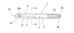
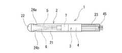
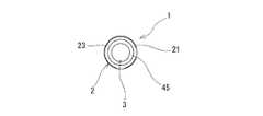
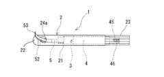
本発明の骨折部固定具1は、筒状スリーブ2と、スリーブ2内に軸方向に移動可能に収納されたフックピン保有部3(フックピン組立体)とからなる。スリーブ2は、先端閉塞部22と、先端部側部に設けられた2つの側孔24a,24bとを備え、フックピン保有部3は、保有部本体(組立体本体)4と、保有部本体4より先端方向に延び、フックピン保有部3の後方からの押込により、スリーブ2の側孔24a,24bより突出する2本のフックピン5,6とを備える。2本のフックピン5,6は、基部54,64と、基部54,64より先端方向に延び、かつ細長い平板状の本体部51,61を備え、さらに、2本のフックピン5,6は、本体部51,61における軸方向上部51a,61aが近接し、軸方向下部51b,61bが離間し、一方のフックピン5,6の本体部51,61は一方の側部下方に傾斜した状態にて軸方向に延び、他方のフックピン5,6の本体部51,61は他方の側部下方に傾斜した状態で軸方向に延びるものとなっている。さらに、本体部51,61は、徐々に肉薄となりかつフックピン5,6の外側面方向に湾曲した骨内進入用薄肉先端部52,62を備える。スリーブ2は、先端閉塞部22の内面に形成され、2つの側孔24a,24b間に位置し後方に突出しかつ上下方向に延びる頂部29と、頂部29の両側部に設けられ、側孔24a,24bに向かって延びる2つのフックピン先端部誘導面26a,26bを備える。フックピン5,6の骨内進入用薄肉先端部52,62は、フックピン保有部3の後方からの押込により、スリーブ2の側孔24a,24bより斜め上方に向かって突出するものとなっている。 The fracture part fixing tool 1 of the present invention includes a
図1ないし図13に示すように、この実施例の骨折部固定具1は、筒状スリーブ2と、スリーブ2内に軸方向に移動可能に収納されたフックピン保有部3(フックピン組立体)とからなる。フックピン保有部3は、フックピン組立体により構成されている。 As shown in FIGS. 1 to 13, the fracture fixing device 1 of this embodiment includes a
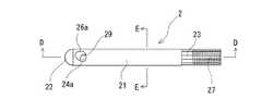
筒状スリーブ2は、図1、図15ないし図17に示すように、筒状本体部21と、先端閉塞部22とを有し、後端が開口し、内部にフックピン保有部3を収納するための収納部25を有する円筒体である。先端閉塞部22の先端面は、半球状、砲弾状などの角部のない形態となっている。そして、この実施例の筒状スリーブ2では、後端部に軸方向に延びる非円筒形要素部23を備えている。具体的には、この実施例では、スリーブ2の後端部は、多角柱状に形成されている。多角柱状としては、具体的には、四角柱から六角柱(図示するものでは、正十二角柱状)であることが好ましく、正多角柱が特に好ましい。なお、非円筒形要素部23は、断面が楕円形の変形円柱状のもの、部分的に形成された軸方向に延びる平坦部、凹部もしくは凸部であってもよい。 As shown in FIGS. 1, 15 to 17, the
筒状スリーブは、図1、図15ないし図17に示すように、先端部の側部に設けられた2つの側孔24a,24bを備えている。この実施例のものでは、2つの側孔24a,24bは、スリーブの先端よりほぼ同じ距離後端側となる位置に設けられている。また、2つの側孔24a,24bは、図1、図15に示すように、軸方向の側部の中心より若干上部に位置するものとなっている。
さらに、この実施例のスリーブ2では、図15ないし図17に示すように、側孔24a,24bは、スリーブ2の側面の上部側から内部下部方向かつ後端方向に斜めに延びており、かつ、側孔24a,24bの内面は、フックピン先端部誘導面26a,26bと段差なく連続している。As shown in FIGS. 1, 15 to 17, the cylindrical sleeve includes two
Furthermore, in the
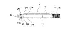
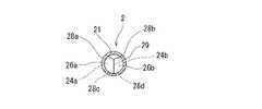
また、このスリーブ2は、先端閉塞部22の内面に形成され、2つの側孔24a,24b間に位置し後方に突出しかつ上下方向に延びる頂部29と、頂部29の両側部に設けられ、側孔24a,24bに向かって延びる2つのフックピン先端部誘導面26a,26bを備えている。図15に示すように、頂部29は、軸方向断面が先端方向に円弧状に窪んだ形態となってる。フックピン先端部誘導面26aは、頂部29から側孔24aに到達する略半筒形状を有するものとなっている。同様に、フックピン先端部誘導面26bは、頂部29から側孔24bに到達する略半筒形状を有するものとなっている。フックピン先端部誘導面26a,26bは、図16に示すように、中央部が膨らむように湾曲している。なお、フックピン先端部誘導面26a,26bは、直線状(直管状)に延びるものであってもよい。 The
そして、この実施例のスリーブ2では、図16および図17に示すように、フックピン先端部誘導面26aは、頂部29の上端から側孔24aの上端に到達する天面部28aを持ち、同様に、フックピン先端部誘導面26bは、頂部29の上端から側孔24bの上端に到達する天面部28bを持っている。このため、後述するフックピン5,6の先端は、フックピン先端部誘導面26a,26bに当接し、その内面形状に従って、側孔24a,24bに誘導される。さらに、この実施例のスリーブ2では、図16および図17に示すように、フックピン先端部誘導面26aは、頂部29の下端から側孔24aの下端に到達する底面部28cを持ち、同様に、フックピン先端部誘導面26bは、頂部29の下端から側孔24bの下端に到達する底面部28dを持っている。底面部28c、29dは、スリーブ2の内部の底面部を若干削り取ることにより形成されている。 In the
筒状スリーブ2としては、外径が6〜12mmであることが好ましく、特に、8.5〜10.5mmが好ましく、全長が60〜140mmであることが好ましく、特に、90〜120mmであることが好ましい。また、非円筒形要素部23の軸方向長は、20〜50mmであることが好ましく、特に、30〜40mmが好ましい。
また、側孔24a,24bの開口面積は、スリーブ外径により相違するが、12.6〜50.3mm2程度が好ましく、特に、19.6〜28.3mm2が好ましい。また、スリーブ2の先端から側孔24a,24bの先端間の距離は、2〜10mmが好ましく、スリーブ2の先端から側孔24a,24bの基端間の距離は、5〜15mmが好ましい。The
Moreover, although the opening area of the side holes 24a and 24b changes with sleeve outer diameters, about 12.6-50.3mm <2 > is preferable and 19.6-28.3mm <2 > is especially preferable. Further, the distance between the distal end of the
なお、筒状スリーブとしては、図32ないし図34に示す実施例の骨折部固定具110にて用いられているようなタイプのスリーブ112であってもよい。この実施例のスリーブ112は、先端部外面に螺旋状のタップ113を備えている。具体的には、スリーブ112の先端部は、小径部114となっており、その小径部114の全体に延びるように螺旋状タップ113が設けられている。また、側孔24a、24b部分では、螺旋状タップ113は欠損している。螺旋状タップ113の外径は、スリーブ112の本体部121の外径より若干大きく、挿入される骨孔を切削可能なものとなっている。 The cylindrical sleeve may be a
次に、フックピン保有部3について説明する。
フックピン保有部3は、図20に示すように、保有部本体4より先端方向に延び、フックピン保有部3の後方からの押込により、スリーブ2の側孔24a,24bより突出する2本のフックピン5,6とを備える。そして、2本のフックピン5,6は、基部54,64と、基部54,64より先端方向に延び、かつ細長い平板状の本体部51,61を備える。
さらに、2本のフックピン5,6は、本体部51,61における軸方向上部51a,61aが近接し、軸方向下部51b,61bが離間し、一方のフックピン5,6の本体部51,61は一方の側部下方に傾斜した状態にて軸方向に延び、他方のフックピン5,6の本体部51,61は他方の側部下方に傾斜した状態で軸方向に延びるものとなっている。また、2本のフックピン5,6は、接触することなく、軸方向にのびている。Next, the hook
As shown in FIG. 20, the hook
Further, the two
この実施例では、図1ないし図13、図18ないし図20に示すように、フックピン保有部3は、複数の部材を組み立てることにより形成されたフックピン組立体により構成されている。なお、フックピン保有部3は、組立体(組立物)に限定されるものではなく、一体物であってもよい。一体物は、金属材を切削加工すること、鋳造すること、両者を組み合わせることにより、作成することができる。
フックピン保有部3は、保有部本体4を構成する本体部材と、本体部材4に装着された2本のフックピン5,6と、フックピン5,6の本体部材4からの離脱を防止するリング状部材7とを備えている。
保有部本体(本体部材)4は、図18ないし図20に示すように、円柱状体であり、本体部41と、本体部41より先端方向に延びるフックピン保持部42と、本体部41より後端方向に延びる小径後端部45とを備える。In this embodiment, as shown in FIG. 1 to FIG. 13 and FIG. 18 to FIG. 20, the hook
The hook
As shown in FIGS. 18 to 20, the holding unit main body (main body member) 4 is a columnar body, and includes a
フックピン保持部42は、本体部41より小径となっており、フックピン5,6の基部54,64を収納するための収納用凹部43,44を備えている。収納用凹部43,44は、フックピン保持部42の側面より、中心方向に延び、かつ所定長軸方向に延びるものとなっている。また、収納用凹部43,44は、フックピン5,6の基端凸部54a,64aを収納するための凹部拡張部43a,44aを備えている。凹部拡張部43a,44aは、凹部の他の部分より、円周長が長くなっている。収納用凹部43、44は、図19に示すように、フックピン保持部42の外周面より中心方向に延びており、かつ、両者が向かい合わないように形成されている。具体的には、収納用凹部43と収納用凹部44間の角度が、50〜120度となるように、形成されている。なお、収納用凹部43と収納用凹部44間の角度は、70〜100度であることが好ましい。 The hook
そして、本体部材4のフックピン保持部42の収納用凹部43、44に、フックピン5,6の基部54,64が収納され、さらに、フックピン5,6の基部54,64およびフックピン保持部42は、リング状部材7により被包されている。リング状部材7は、外径が、保有部本体(本体部材)4の本体部41とほぼ同一外径もしくは若干小さく、内径が、フックピン保持部42の外径とほぼ同一もしくは若干小さいものが用いられている。また、収納用凹部43、44の深さは、フックピン5,6の基部54,64の幅とほぼ同じもしくは若干大きいものとなっている。このため、収納用凹部43、44は、フックピン5,6の基部54,64の側部が突出することなく収納している。 The
フックピン5,6は、図18、図20に示すように、上述した基部54,64と、基部54,64より先端側に位置し、かつ、本体部材4のフックピン保持部42より突出する本体部51,61とを有する。そして、本体部51,61は、細長い平板状に形成されており、かつ、徐々に肉薄となりかつフックピン5,6の外側面方向に湾曲した骨内進入用薄肉先端部52,62を備える。 As shown in FIGS. 18 and 20, the hook pins 5 and 6 are the
この実施例では、フックピン5,6は、所定幅先端まで延びるものとなっており、本体部51,61の途中より、徐々に肉薄となるとともに、外側面方向に湾曲している。本体部51,61の先端部に位置する骨内進入用薄肉先端部52,62においても徐々に肉薄となるとともに、外側面方向に湾曲している。骨内進入用薄肉先端部52,62においても、徐々に肉薄となるとともに、さらに外側面方向に湾曲している。このため、フックピン5,6は、外側面に比べて曲率の大きい内側面を備えるものとなっている。言い換えれば、フックピン5,6は、外側面が若干湾曲し、内側面側が徐々に外側面に近づくように外側面に比べて大きく湾曲することにより、湾曲しかつ先端に向かって薄肉となっている。そして、骨内進入用薄肉先端部52,62の先端53,63は、最も肉薄となっており、骨への刺入端を形成している。 In this embodiment, the hook pins 5 and 6 extend to the tip of a predetermined width, and gradually become thinner from the middle of the
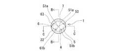
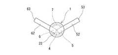
そして、図4及び図6に示すように、2本のフックピン5,6は、本体部51,61における軸方向上部51a,61aが近接し、軸方向下部51b,61bが離間し、かつ、両者は向かい合わないように配置されている。具体的には、2本のフックピン5,6の本体部51,61の軸方向上部51a,61aは、スリーブ2の中心軸付近に位置し、軸方向下部51b,61bは、向かい合わないように離間し、かつスリーブ2の内面付近に位置している。これにより、一方のフックピン5,6の本体部51,61は一方の側部下方に傾斜した状態にて軸方向に延び、他方のフックピン5,6の本体部51,61は他方の側部下方に傾斜した状態で軸方向に延びるものとなっている。言い得れば、2本のフックピン5,6は、向かい合うことなく両者の上部が頂部を形成するように傾斜配置されている。 As shown in FIGS. 4 and 6, the two
これは、上述したように、フックピン保持部42に設けられたフックピン収納用凹部43と収納用凹部44間の角度が、50〜120度となるように形成されているため、その凹部に収納されることにより、2本のフックピン5,6の本体部51,61における両者間の角度も、50〜120度となっている。
そして、フックピン5,6の骨内進入用薄肉先端部52,62は、フックピン保有部3の後方からの押込により、図10、図11および図12に示すように、スリーブ2の側孔24a,24bより斜め上方に向かって突出する。言い換えれば、図11に示すように、先端視においてV字状に突出する。このため、骨片への刺入抵抗が低く、かつ、刺入後において、骨片の回転を確実に規制できる。As described above, since the angle between the hook
The thin-walled
また、この実施例の骨折部固定具1では、図1ないし図7に示すように、筒状スリーブ2内に、2本のフックピン5,6の骨内進入用薄肉先端部52,62が、側孔24a,24b内に位置し、かつ、スリーブ2より突出しないように、フックピン保有部3は収納されている。
この実施例のものでは、2本のフックピン5,6は、先端部において、スリーブ2の側孔24a,24bの内縁または内面と接触し、かつ、スリーブ2の内面の他の部分と実質的に接触していない。特に、この実施例では、2本のフックピン5,6は、先端部が側孔24a,24b内に位置し、かつ、先端部において、スリーブ2の側孔24a,24bの後端部の内縁に当接し、かつ若干押圧するものとなっている。このため、スリーブ2内におけるフックピン保有部3の移動が規制されている。Moreover, in the fracture | rupture part fixing tool 1 of this Example, as shown in FIG. 1 thru | or 7, the thin-walled front-end |
In this embodiment, the two
また、この実施例では、図8に示すように、フックピン5,6の先端は、フックピン先端部誘導面26a,26bの付近に位置するもしくは当接している。具体的には、フックピン5,6の内側面の先端が、フックピン先端部誘導面26a,26bの付近に位置もしくは当接している。 Further, in this embodiment, as shown in FIG. 8, the tips of the hook pins 5 and 6 are positioned or abutted in the vicinity of the hook pin tip portion guide surfaces 26a and 26b. Specifically, the tips of the inner surfaces of the hook pins 5 and 6 are positioned or abutted in the vicinity of the hook pin tip portion guide surfaces 26a and 26b.
そして、フックピン5,6は、後述するフックピン保有部押込具9のフックピン保有部3の押圧により、図10ないし図13に示すように、保有部3とともに先端側に押され、先端部52,62は、スリーブ2の先端閉塞部22のフックピン先端部誘導面26a,26bに摺接し、誘導され、側孔24a,24bから突出する。そして、フックピン5,6の骨内進入用薄肉先端部52,62は、図10ないし図13に示すように、斜め上方に向かって突出し、かつ、突出した骨内進入用薄肉先端部52,62は、その内側面が先端方向を向き、外側面が後端方向を向き、骨内進入用薄肉先端部52,62の先端53、63は、スリーブの軸方向に直交する方向を向くものとなる。 The hook pins 5 and 6 are pushed to the distal end side together with the holding
より具体的には、図8に示すように、2本のフックピン5,6は、軸方向に延びるすべての角部が面取りされている。そして、2本のフックピン5,6は、面取りされた外側面の一方の角部(具体的には、軸方向下部の角部)もしくはその付近が、スリーブ2の側孔24a,24bの後端部の内縁に当接している。 More specifically, as shown in FIG. 8, the two
そして、この実施例では、図8に示すように、2本のフックピン5,6は、少なくとも、フックピン保持部42より突出する部分において、両者は接触することなく先端まで延びている。具体的には、2本のフックピン5,6の上部内縁51a,61a間には、隙間があり、この隙間は、本体部41の基端側部分において狭く、先端に向かって広がっている。 In this embodiment, as shown in FIG. 8, the two
保有部本体(本体部材)4の小径後端部45は、図7、図18および図20に示すように、本体部41の後端より後方に延び、かつ、本体部より外径が小さい円柱部である。そして、小径後端部45は、フックピン保有部側螺合部46を備える。この実施例では、フックピン保有部側螺合部46は、小径後端部45の後端より先端方向に延びる凹部とこの凹部の内面に形成された雌ねじにより形成されている。なお、フックピン保有部側螺合部46は、小径後端部45の外面に設けた雄ねじにより形成してもよい。 The small-diameter
次に、本発明の骨折部固定術用器具10について、図面を用いて説明する。
図21ないし図28に示すように、本発明の骨折部固定術用器具10は、筒状スリーブ2と、スリーブ2内に軸方向に移動可能に収納されたフックピン保有部3とからなる骨折部固定具1と、骨折部固定具のフックピン保有部3の骨への刺入作業および骨に刺入されたフックピン保有部3の抜去作業を行うための骨折部固定具操作用具とからなる。Next, the
As shown in FIGS. 21 to 28, the
骨折部固定具1としては、筒状スリーブ2と、スリーブ2内に軸方向に移動可能に収納されたフックピン保有部3と有するものが用いられる。そして、スリーブ2は、先端閉塞部22と、先端部側部に設けられた2つの側孔24a,24bと、後端部外面に設けられた軸方向に延びる非円筒形要素部23(具体的には、軸方向に所定長延びる平坦部、凹部もしくは凸部)と、後端部の内面に設けられた雌ねじ部27を備える。フックピン保有部3は、保有部本体4と、保有部本体4より先端方向に延び、フックピン保有部3の先端方向への移動により、先端部がスリーブ2の側孔24a,24bより突出する2本のフックピン5,6と、後端より先端方向に延びるフックピン保有部側螺合部46を備える。2本のフックピン5,6は、基部54,64と、徐々に肉薄となりかつ外側面方向に湾曲した骨内進入用薄肉先端部52,62を備える。 As the fracture part fixing tool 1, one having a
図21に示すように、骨折部固定具操作用具は、スリーブ回転規制具8と、フックピン保有部押込具9と、フックピン保有部引戻具11とを備える。
スリーブ回転規制具8は、筒状本体部81と、筒状本体部81の先端部83に形成され、スリーブ2の後端部23を収納可能かつ非円筒形要素部に対応した内面形態84を有し、スリーブ2の後端部23を収納し、回転を規制するものとなっている。As shown in FIG. 21, the fracture fixing tool operating tool includes a sleeve rotation restricting tool 8, a hook pin holding
The sleeve rotation restricting tool 8 is formed in a cylindrical
フックピン保有部押込具9は、スリーブ回転規制具8の筒状本体部81を挿通可能な筒状部材91と、筒状部材91の後端部に設けられたハンドル92とを備え、筒状部材91は、スリーブ2の後端部内に進入可能であり、外面にスリーブ2の雌ねじ部27と螺合可能な雄ねじ部94を備える先端部93と、(雄ねじ部と雌ねじ部の螺合の進行により)フックピン保有部3と当接し、フックピン保有部3を先端方向に押し込むための押込用当接部95(この実施例では、先端部の先端により形成されている)とを備える。 The hook pin holding
フックピン保有部引戻具11は、スリーブ回転規制具8の内部に挿入可能であるシャフト部12と、シャフト部12の後端部に設けられた操作部13とを備え、シャフト部12は、フックピン保有部3のフックピン保有部側螺合部46(具体的には、凹部内に進入可能かつ凹部の雌ねじ部と螺合可能な雄ねじ部)と螺合可能な引戻部材側螺合部14を備えている。 The hook pin holding
骨折部固定具としては、筒状スリーブ2と、スリーブ2内に軸方向に移動可能に収納されたフックピン保有部3とを備えるものが使用される。さらに、スリーブ2としては、先端閉塞部22と、先端部側部に設けられた2つの側孔24a,24bと、後端部外面に設けられた軸方向に延びる非円筒形要素部23(具体的には、軸方向に所定長延びる平坦部、凹部もしくは凸部)と、後端部の内面に設けられた雌ねじ部27を備えるものが使用される。フックピン保有部3としては、保有部本体4と、保有部本体4より先端方向に延び、フックピン保有部3の先端方向への移動により、先端部がスリーブ2の側孔24a,24bより突出する2本のフックピン5,6と、後端より先端方向に延びるフックピン保有部側螺合部46を備えるものが使用される。
具体的には、骨折部固定具としては、上述した骨折部固定具1が好適に使用される。なお、使用される骨折部固定具としては、上述した骨折部固定具1に限定されるものではない。As the fracture part fixing tool, one having a
Specifically, the above-described fracture fixing tool 1 is preferably used as the fracture fixing tool. In addition, as a fracture part fixing tool used, it is not limited to the fracture part fixing tool 1 mentioned above.
この実施例の骨折部固定術用器具10は、骨折部固定具1と、骨折部固定具1部3の骨への固定作業および抜去作業を行うための骨折部固定具操作用具とからなる。
図21に示すように、骨折部固定具操作用具は、スリーブ回転規制具8と、フックピン保有部押込具9と、フックピン保有部引戻具11とを備える。
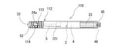
スリーブ回転規制具8は、図21ないし図24に示すように、筒状本体部81と、筒状本体部81より側方に延びるグリップ82を備えている。スリーブ回転規制具8は、スリーブ2の後端部23を収納し、作業時における回転を規制するものである。この実施例では、グリップ82は、細長い平板状部材が用いられており、筒状本体部81の後端部に設けられ、側部の下方に延びるものとなっている。The
As shown in FIG. 21, the fracture fixing tool operating tool includes a sleeve rotation restricting tool 8, a hook pin holding
As shown in FIGS. 21 to 24, the sleeve rotation restricting tool 8 includes a cylindrical
そして、筒状本体部81は、その先端部に設けられ、スリーブ2の後端部23を収納可能かつ非円筒形要素部に対応した内面形態84を有している。この実施例では、スリーブ2の非円筒形要素部は、多角柱状に形成されているため、内面形態84は、これに対応する多角柱状となっている。なお、内面形態84は、非円筒形要素部23を収納し、回転を規制できるものであればよい。例えば、断面が楕円形の変形円柱状のもの、部分的に形成された軸方向に延びる平坦部、凹部もしくは凸部を有するものであってもよい。また、筒状本体部81の先端部は、スリーブ2の後端部23のみ(一部もしくは全体)を収納可能なものとなっている。このため、筒状本体部81の先端部は内部に、スリーブ2の後端部23の後端30と当接可能な段差部85(具体的には、内径小径部)を備えている。そして、スリーブ回転規制具8は、筒状本体部81内と連通し、かつ先端および後端が開口した貫通路を備えている。 The cylindrical
フックピン保有部押込具9は、スリーブ2内のフックピン保有部3を後方より押圧し、フックピン5,6をスリーブより突出させるための器具である。フックピン保有部押込具9は、図21ないし図26および図28に示すように、スリーブ回転規制具8の筒状本体部81を挿通可能な筒状部材91と、筒状部材91の後端部に設けられたハンドル92とを備える。そして、フックピン保有部押込具9は、筒状部材91内およびハンドル92内を延び、筒状部材91の先端からハンドル92の基端に到達する貫通路を備えている。 The hook pin holding
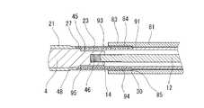
そして、筒状部材91は、スリーブ2の後端部内に進入可能であり、外面にスリーブ2の雌ねじ部27と螺合可能な雄ねじ部94を備える先端部93と、雄ねじ部94と雌ねじ部27の螺合の進行により、フックピン保有部3側の当接部48と当接し、フックピン保有部3を先端方向に押し込むための押込用当接部95とを備える。具体的には、フックピン保有部3側の当接部48は、本体部41の後端部(本体部41と小径後端部の段差部の後端面)により形成されており、フックピン保有部押込具9側の当接部は、先端部の先端により形成されている。 The
図23ないし図28に示すように、スリーブ回転規制具8が、骨折部固定具1のスリーブ2の後端を収納した状態にて、フックピン保有部押込具9は使用される。フックピン保有部押込具9は、筒状部材91がスリーブ回転規制具8内に挿入され、その先端をスリーブ2内に進入させる。そして、スリーブ回転規制具8を保持した状態にて、フックピン保有部押込具9を回転させることにより、フックピン保有部押込具9の雄ねじ部94とスリーブ2の雌ねじ部27は螺合し、押込用当接部(筒状部材91の先端面)95は、フックピン保有部3側の当接部48と当接する。 As shown in FIGS. 23 to 28, the hook pin holding
さらに、フックピン保有部押込具9を回転させることにより、両者間の螺合の進行ともに、フックピン保有部3は、スリーブ2内を軸方向先端側に移動する。フックピン保有部押込具9の回転(前進)は、フックピン保有部押込具9のハンドル92が、スリーブ回転規制具8の後端に当接することにより終了となる。なお、フックピン保有部押込具9の前進距離は、フックピン保有部押込具9の雄ねじ部94とスリーブ2の雌ねじ部27の一方もしくは両者の長さにより規制してもよい。 Further, by rotating the hook pin holding
そして、図25および図26に示すように、フックピン5,6の先端部は、側孔24a,24bより突出する。特に、この実施例では、上述した骨折部固定具1を用いているため、図10ないし図13に示すような形態にて、骨内進入用薄肉先端部52,62は、側孔24a,24bから突出する。 As shown in FIGS. 25 and 26, the tip portions of the hook pins 5 and 6 protrude from the side holes 24a and 24b. In particular, in this embodiment, since the above-described fracture fixing tool 1 is used, the thin-walled
フックピン5,6は、上述したフックピン保有部押込具9のフックピン保有部3の押圧により、保有部3とともに先端側に押され、先端部52,62は、スリーブ2の先端閉塞部22のフックピン先端部誘導面26a,26bに当接し、かつそれに摺接しながら、側孔24a,24bから突出する。このため、フックピン5,6の骨内進入用薄肉先端部52,62は、図3および図25に示すように、斜め上方に向かって突出し、その先端53、63は、スリーブの軸方向に直交する方向を向く状態となっており、自由に突出させた状態における骨内進入用薄肉先端部52,62は、若干反り返り、側面の外方を向くものとなる。しかし、骨内においては、骨組織の抵抗を受け、また、骨組織の性状により、突出形態は、変化するものと考える。 The hook pins 5 and 6 are pushed to the distal end side together with the retaining
フックピン保有部引戻具11は、図25ないし図27に示すように、フックピン5,6の先端部52,62が突出した状態がフックピン保有部3をスリーブ2の後端方向に引き戻し、突出したフックピン5,6の先端部52,62をスリーブ内に収納するための器具である。 As shown in FIGS. 25 to 27, the hook pin holding
フックピン保有部引戻具11は、図21,図27および図28に示すように、スリーブ回転規制具8の内部(貫通路)に挿入可能であるシャフト部12と、シャフト部12の後端部に設けられた操作部13とを備える。シャフト部12は、フックピン保有部3のフックピン保有部側螺合部46と螺合可能な引戻部材側螺合部14を備えている。シャフト部12は、棒状のもの、具体的には円柱状のシャフトが用いられている。なお、円筒状などの筒状のものであってもよい。 As shown in FIGS. 21, 27, and 28, the hook pin holding
上述したように、ここで使用する骨折部固定具1は、フックピン保有部側螺合部46として、保有部本体4の後端より先端方向に延びる凹部と、凹部の内面に形成された雌ねじを備えている。このため、この実施例では、引戻部材側螺合部14は、シャフト部12の先端部に設けられ、かつ、上記凹部内に進入可能かつ凹部の雌ねじと螺合可能な雄ねじにより形成されている。 As described above, the fractured portion fixing tool 1 used here has a recess extending in the distal direction from the rear end of the holding portion
そして、この実施例のフックピン保有部引戻具11では、操作部13は、円柱状小径先端部15を備えている。また、この実施例では、フックピン保有部引戻具11とフックピン保有部押込具9は、フックピン保有部引戻具11のフックピン保有部側螺合部46と引戻部材側螺合部14との螺合時において当接する螺合時当接部を備える。そして、螺合時当接部は、座面を形成するものであることが好ましい。この実施例では、座面の一方は、円柱状小径先端部15の先端面16により形成され、座面の他方は、フックピン保有部押込具9のハンドル92の後端開口部の周縁部96により形成される。なお、2つの座面は、低摩擦抵抗にて摺接するものであることが好ましい。 And in the hook pin holding | maintenance
なお、フックピン保有部引戻具11の使用時、すなわち、フックピン5,6の突出した先端部52,62のスリーブ内に収納作業時において、フックピン保有部押込具9を用いないものであってもよい。この場合には、フックピン保有部引戻具11のフックピン保有部側螺合部46と引戻部材側螺合部14との螺合時において当接する螺合時当接部は、フックピン保有部引戻具11の円柱状小径先端部15の先端面にと、スリーブ回転規制具8の後端開口部の周縁部により構成される。そして、両者は、上述したものと同様に、低摩擦抵抗にて摺接する座面を形成することが好ましい。 Even when the hook pin holding
次に、本発明の骨折部固定具1および骨折部固定術用器具10の作用を図面を用いて説明する。
この実施例の骨折部固定具1および骨折部固定術用器具10は、大腿骨の転子部等の大腿骨近位部骨折治療に特に有効である。Next, the operation of the fracture fixing tool 1 and the
The fracture fixing device 1 and the
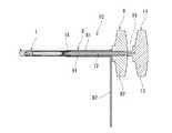
図29ないし図31は、大腿骨の転子部骨折の治療に本発明の骨折部固定具1を用いたものを図示している。大腿骨70の転子部骨折治療において、最初に大腿骨主部71の大転子頂部に、大腿骨主部71の内腔と連通する上部骨孔を形成する。そして、この骨孔より、髄内釘100のステム部101を大腿骨主部71内に挿入し、固定する。そして、髄内釘100に設けられている斜め上方(図29の例では、斜め上方かつ骨片72方向)に延びる貫通部を通過するように、大腿骨主部71の側部から、髄内釘の貫通部を通り、骨片72の中心部に到達するように骨孔を形成する。そして、この骨孔に、本発明の、骨折部固定具1を挿入する。なお、骨折部固定具1は、フックピン5,6の突出時にその先端部が骨片72の上部方向に延びるように配置することが好ましい。 FIG. 29 thru | or 31 has illustrated what used the fracture | rupture part fixing tool 1 of this invention for the treatment of the trochanter part fracture of the femur. In the treatment of the trochanteric fracture of the
そして、そのように骨折部固定具1を配置した後、上述したように、骨折部固定具1の後端部23をスリーブ回転規制具8の先端部内に収納し、その状態を維持し、さらに、フックピン保有部押込具9を先端部より、スリーブ回転規制具8内に挿入し、図25および図26(図27参照)に示すように、フックピン保有部押込具9の先端部93の雄ねじ部94をスリーブ2の雌ねじ部27を螺合させる。そして、フックピン保有部押込具9の押込用当接部(筒状部材91の先端面)95は、フックピン保有部3側の当接部48と当接する。 And after arrange | positioning the fracture part fixing tool 1 in that way, as mentioned above, the rear-
さらに、フックピン保有部押込具9を回転させることにより、両者間の螺合の進行とともに、フックピン保有部3は、スリーブ2内を軸方向先端側に移動し、フックピンの先端部52,62は、図30に示すように、側孔24a,24bから突出し、骨片72内に進入する。骨片72は、その内部に進入したフックピン5,6の骨内進入用薄肉先端部52,62により、固定され、かつ回旋が規制される。これにより、骨折部固定具1のフックピン突出操作が終了され、フックピン保有部押込具9は、逆方向に回転させることにより、フックピン保有部3より離脱され、スリーブ回転規制具8の後方に移動することにより、スリーブより離脱する。そして、骨折部固定具1は、図31に示すように、髄内釘100内に挿入された固定ネジ103により髄内釘100に固定される。また、髄内釘100の上部には、シールネジ102が取り付けられ、上部開口は閉塞されている。
これにより、骨折部固定具1の骨内固定手技が終了する。Further, by rotating the hook pin holding
Thereby, the intraosseous fixation technique of the fracture | rupture part fixing tool 1 is complete | finished.
そして、骨折部固定具1は、骨内への設置手技後、所定時間経過した場合、また、手技中の事情などにより、大腿骨より抜去する必要が生じる場合がある。この場合には、骨折部固定具1の設置手技と同様に、骨折部固定具1の後端部23をスリーブ回転規制具8の先端部内に収納し、その状態を維持し、さらに、フックピン保有部押込具9を先端部より、スリーブ回転規制具8内に挿入し、図27に示すように、フックピン保有部押込具9の先端部93の雄ねじ部94とスリーブ2の雌ねじ部27とを螺合させる。 Then, the fractured part fixing tool 1 may need to be removed from the femur when a predetermined time has elapsed after the installation procedure in the bone or due to circumstances during the procedure. In this case, the
続いて、フックピン保有部引戻具11をフックピン保有部押込具9内に挿入し、フックピン保有部引戻具11のフックピン保有部側螺合部46と引戻部材側螺合部14とを螺合させる。この螺合を進行させることにより、フックピン保有部引戻具11の先端部である円柱状小径先端部15の先端面は、フックピン保有部押込具9のハンドル92の後端開口部の周縁部96に当接する。さらに、フックピン保有部引戻具11の回転を継続し、螺合を進行させることにより、フックピン保有部3は、スリーブ2を徐々に後端方向に移動し、これに従い、骨内に進入したフックピン5,6の骨内進入用薄肉先端部52,62は、スリーブ2内に収納される。 Subsequently, the hook pin holding
そして、フックピン5,6の骨内進入用薄肉先端部52,62が、スリーブの外面より突出しない状態とすることにより、フックピン保有部3の引き戻し操作は終了する。そして、骨折部固定具1を接続されているスリーブ回転規制具8、フックピン保有部押込具9およびフックピン保有部引戻具11とともに後方へ移動することにより、骨折部固定具1は、骨内より抜去される。 And the pull-back operation of the hook pin holding |
また、本発明の骨折部固定術用器具としては、図35に示す実施例の骨折部固定術用器具10aのように、フックピン保有部殴打具20を備えるものであってもよい。
この実施例の骨折部固定術用器具10aは、図35に示すように、骨折部固定具1と骨折部固定具操作用具を備える。骨折部固定術用器具10aでは、骨折部固定具操作用具は、スリーブ回転規制具8と、フックピン保有部押込具9と、フックピン保有部殴打具20と、上述したフックピン保有部引戻具11(図35には図示しない)とを備えるものとなっている。Moreover, as a fracture | rupture part fixing operation instrument of this invention, like the fracture | rupture
As shown in FIG. 35, the
骨折部固定具1、スリーブ回転規制具8、フックピン保有部押込具9、フックピン保有部引戻具11は、上述したものと同じである。
なお、骨折部固定具1のフックピン保有部3の後端面は、中心部に位置する上述したフックピン保有部側螺合部46の開口(後端開口)と、開口の周縁に形成された環状平坦面を有している。具体的にはフックピン保有部3の保有部本体(本体部材)4の小径後端部45の後端面45aは、中心部に螺合部46の開口と、それを取り囲むように設けられた環状平坦面を備えている。この環状平坦面が、後述するフックピン保有部殴打具20により、強く押されることにより、フックピン保有部3は、前進する。The fracture part fixing tool 1, the sleeve rotation restricting tool 8, the hook pin holding
In addition, the rear end surface of the hook
フックピン保有部殴打具20は、図35ないし図37に示す様に、殴打によりフックピンをスリーブより突出させるための器具である。フックピン保有部殴打具20は、フックピン保有部4の後端面45aに当接可能な先端面37aを有するシャフト部37と、シャフト部37の後端部に設けられた殴打用基部38とを備えている。シャフト部37は、フックピン保有部押込具9内およびスリーブ2の後端部内に進入可能なものとなっている。特に、この実施例では、シャフト部37は、柱状体(具体的には、円柱状、多角柱状)のものとなっている。なお、シャフト部は、筒状(例えば、円筒状、多角筒状)のものであってもよい。特に、この実施例のシャフト部37は、直径(外径)が、フックピン保有部押込具9の筒状部材91の内径およびスリーブ2の後端部の内径より、小さいものとなっている。 As shown in FIG. 35 to FIG. 37, the hook pin holding
また、シャフト部37の先端面37aは、上述したフックピン保有部4の後端面(上述した環状平坦面)と当接可能な平坦面となっている。そして、殴打用基部38は、シャフト部より大きく形成された膨出部となっており、殴打用後端面39を有している。殴打用後端面は、平坦面であることが好ましい。
この実施例の骨折部固定術用器具では、フックピンのスリーブからの突出操作を、フックピン保有部押込具9を用いたゆっくりとした突出操作と、フックピン保有部殴打具20を用いた短時間の突出操作とを選択できるものとなっている。突出操作の選択は、患者の骨の状態等を考慮して行われる。Further, the
In the fracture fixing device of this embodiment, the protrusion operation of the hook pin from the sleeve includes a slow protrusion operation using the hook pin holding
この実施例の骨折部固定術用器具10aの作用を図35ないし図37を用いて説明する。
骨折部固定具1を骨接合部位に配置した後、骨折部固定具1の後端部23をスリーブ回転規制具8の先端部内に収納し、その状態を維持し、さらに、フックピン保有部押込具9を先端部より、スリーブ回転規制具8内に挿入し、図36および図37に示すように、フックピン保有部押込具9の先端部93の雄ねじ部94をスリーブ2の雌ねじ部27に螺合させる。The operation of the
After the fractured part fixing tool 1 is arranged at the osteosynthesis site, the
続いて、フックピン保有部押込具9内に、フックピン保有部殴打具20をシャフト部37側から挿入し、フックピン保有部3の後端面45aに、シャフト部37の先端面37aが当接した状態とする。そして、この状態において、フックピン保有部殴打具20の殴打用基部38の殴打用後端面39を殴打具(例えば、メディカルハンマー)にて殴打する。これにより、フックピン保有部3は、スリーブ2内を軸方向先端側に移動し、フックピンの先端部62は、図37に示すように、側孔から突出し、骨片に進入する。骨片は、その内部に進入したフックピンの骨内進入用薄肉先端部62により、固定され、かつ回旋が規制される。これにより、骨折部固定具1のフックピン突出操作が終了する。そして、フックピン保有部殴打具20をフックピン保有部押込具9より抜去し、続いて、フックピン保有部押込具9を、螺合進行と逆方向に回転させることにより、フックピン保有部3より、フックピン保有部押込具9を離脱させ、さらに、スリーブ回転規制具8の後方に移動することにより、スリーブより離脱する。そして、骨折部固定具1は、図31と同様に、髄内釘100内に挿入された固定ネジ103により髄内釘100に固定される。また、髄内釘100の上部には、シールネジ102が取り付けられ、上部開口は閉塞されている。これにより、骨折部固定具1の骨内固定手技が終了する。 Subsequently, the hook pin holding
そして、骨折部固定具1は、骨内への設置手技後、所定時間経過した場合、また、手技中の事情などにより、大腿骨より抜去する必要が生じる場合がある。この場合には、骨折部固定具1の後端部23をスリーブ回転規制具8の先端部内に収納し、その状態を維持し、さらに、フックピン保有部押込具9を先端部より、スリーブ回転規制具8内に挿入し、図27に示すように、フックピン保有部押込具9の先端部93の雄ねじ部94とスリーブ2の雌ねじ部27とを螺合させる。 Then, the fractured part fixing tool 1 may need to be removed from the femur when a predetermined time has elapsed after the installation procedure in the bone or due to circumstances during the procedure. In this case, the
続いて、フックピン保有部引戻具11をフックピン保有部押込具9内に挿入し、フックピン保有部引戻具11のフックピン保有部側螺合部46と引戻部材側螺合部14とを螺合させる。この螺合を進行させることにより、フックピン保有部引戻具11の先端部である円柱状小径先端部15の先端面は、フックピン保有部押込具9のハンドル92の後端開口部の周縁部96に当接する。さらに、フックピン保有部引戻具11の回転を継続し、螺合を進行させることにより、フックピン保有部3は、スリーブ2を徐々に後端方向に移動し、これに従い、骨内に進入したフックピン5,6の骨内進入用薄肉先端部52,62は、スリーブ2内に収納される。 Subsequently, the hook pin holding
そして、フックピン5,6の骨内進入用薄肉先端部52,62が、スリーブの外面より突出しない状態とすることにより、フックピン保有部3の引き戻し操作は終了する。そして、骨折部固定具1を接続されているスリーブ回転規制具8、フックピン保有部押込具9およびフックピン保有部引戻具11とともに後方へ移動することにより、骨折部固定具1は、骨内より抜去される。 And the pull-back operation of the hook pin holding |
1 骨折部固定具
2 筒状スリーブ
3 フックピン保有部(フックピン組立体)
4 保有部本体(組立体本体)
5、6 フックピン
8 スリーブ回転規制具
9 フックピン保有部押込具
10 骨折部固定術用器具
11 フックピン保有部引戻具
20 フックピン保有部殴打具
24a,24b 側孔
52,53 骨内進入用薄肉先端部DESCRIPTION OF SYMBOLS 1 Fracture
4. Holding unit body (assembly body)
5, 6 Hook pin 8 Sleeve
Claims (20)
Translated fromJapanese前記スリーブは、先端閉塞部と、先端部側部に設けられた2つの側孔とを備え、
前記フックピン保有部は、保有部本体と、前記保有部本体より先端方向に延び、前記フックピン保有部の後方からの押込により、前記スリーブの前記側孔より突出する2本のフックピンとを備え、
前記2本のフックピンは、基部と、前記基部より先端方向に延び、かつ細長い平板状の本体部を備え、さらに、前記2本のフックピンは、前記本体部における軸方向上部が近接し、軸方向下部が離間し、一方のフックピンの前記本体部は一方の側部下方に傾斜した状態にて軸方向に延び、他方のフックピンの前記本体部は他方の側部下方に傾斜した状態で軸方向に延びるものとなっており、さらに、前記本体部は、徐々に肉薄となりかつ前記フックピンの外側面方向に湾曲した骨内進入用薄肉先端部を備え、
前記スリーブは、前記先端閉塞部の内面に形成され、前記2つの側孔間に位置し後方に突出しかつ上下方向に延びる頂部と、前記頂部の両側部に設けられ、前記側孔に向かって延びる2つのフックピン先端部誘導面を備え、
前記2本のフックピンの前記骨内進入用薄肉先端部は、前記フックピン保有部の後方からの押込により、前記スリーブの前記側孔より斜め上方に向かって突出するものとなっていることを特徴とする骨折部固定具。A fractured portion fixing tool comprising a cylindrical sleeve and a hook pin holding portion accommodated in the sleeve so as to be movable in the axial direction,
The sleeve includes a distal end blocking portion and two side holes provided in the distal end side portion,
The hook pin holding portion includes a holding portion main body, and two hook pins extending from the holding portion main body in a distal direction and projecting from the side hole of the sleeve by pressing from the rear of the hook pin holding portion,
The two hook pins include a base and a long and flat plate-like main body extending from the base in the distal direction. Further, the two hook pins are close to each other in the axial direction in the main body, and are axially The lower portion is spaced apart, and the main body portion of one hook pin extends in the axial direction in a state inclined downwardly on one side portion, and the main body portion of the other hook pin extends in the axial direction in a state inclined downwardly on the other side portion. Furthermore, the main body portion is provided with a thin-walled distal end portion for entering the bone that gradually becomes thin and is curved toward the outer surface of the hook pin,
The sleeve is formed on an inner surface of the tip closing portion, is located between the two side holes, protrudes rearward and extends in the vertical direction, and is provided on both sides of the top portion and extends toward the side hole. With two hook pin tip guide surfaces,
The thin-walled distal end portions for entering into the bone of the two hook pins protrude obliquely upward from the side holes of the sleeve by being pushed from behind the hook pin holding portion. Fracture fixing tool.
前記スリーブは、先端閉塞部と、先端部側部に設けられた2つの側孔と、後端部外面に設けられた軸方向に延びる非円筒形要素部と、後端部の内面に設けられた雌ねじ部を備え、
前記フックピン保有部は、保有部本体と、前記保有部本体より先端方向に延び、前記フックピン保有部の先端方向への移動により、先端部が前記スリーブの前記側孔より突出する2本のフックピンと、後端より先端方向に延びるフックピン保有部側螺合部を備え、前記2本のフックピンは、基部と、徐々に肉薄となりかつ外側面方向に湾曲した骨内進入用薄肉先端部を備え、
前記骨折部固定具操作用具は、スリーブ回転規制具と、フックピン保有部押込具と、フックピン保有部引戻具とを備え、
前記スリーブ回転規制具は、筒状本体部と、前記筒状本体部の先端部に形成され、前記スリーブの後端部を収納可能かつ前記非円筒形要素部に対応した内面形態を有し、前記スリーブの後端部を収納し、回転を規制するものとなっており、
前記フックピン保有部押込具は、前記スリーブ回転規制具の前記筒状本体部を挿通可能な筒状部材と、前記筒状部材の後端部に設けられたハンドルとを備え、前記筒状部材は、前記スリーブの後端部内に進入可能であり、外面に前記スリーブの前記雌ねじ部と螺合可能な雄ねじ部を備える先端部と、前記フックピン保有部と当接し、前記フックピン保有部を先端方向に押し込むための押込用当接部とを備え、
前記フックピン保有部引戻具は、前記スリーブ回転規制具の内部に挿入可能であるシャフト部と、前記シャフト部の後端部に設けられた操作部とを備え、前記シャフト部は、前記フックピン保有部の前記フックピン保有部側螺合部と螺合可能な引戻部材側螺合部を備えていることを特徴とする骨折部固定術用器具。A fractured part fixing tool comprising a cylindrical sleeve and a hook pin holding part accommodated in the sleeve so as to be movable in the axial direction, and a bone inserting operation of the hook pin holding part of the fractured part fixing tool and a bone A fracture fixing device comprising a fracture fixing tool operating tool for performing an extraction operation of the inserted hook pin holding portion,
The sleeve is provided on a front end closing portion, two side holes provided on a front end side portion, an axially extending non-cylindrical element portion provided on a rear end outer surface, and an inner surface of the rear end portion. With a female thread
The hook pin holding portion includes a holding portion main body, two hook pins extending from the holding portion main body in a distal end direction, and a tip portion protruding from the side hole of the sleeve by movement of the hook pin holding portion in the distal end direction. The hook pin holding portion side threading portion extending in the distal direction from the rear end, the two hook pins are provided with a base portion and a thin distal portion for intraosseous entry gradually becoming thinner and curved in the outer surface direction,
The fracture part fixing tool operating tool comprises a sleeve rotation restricting tool, a hook pin holding part pushing tool, and a hook pin holding part pulling tool,
The sleeve rotation restricting tool is formed at a cylindrical main body portion and a front end portion of the cylindrical main body portion, and has an inner surface form capable of storing a rear end portion of the sleeve and corresponding to the non-cylindrical element portion, The rear end of the sleeve is stored, and the rotation is restricted.
The hook pin holding portion pushing tool includes a tubular member that can be inserted through the tubular main body portion of the sleeve rotation restricting tool, and a handle provided at a rear end portion of the tubular member, A front end portion that is capable of entering into the rear end portion of the sleeve and has an external thread portion that can be screwed with the internal thread portion of the sleeve on the outer surface, and abutting the hook pin holding portion, and the hook pin holding portion in the front end direction. A pressing contact portion for pressing,
The hook pin holding part retractor includes a shaft part that can be inserted into the sleeve rotation restricting tool, and an operation part provided at a rear end part of the shaft part, and the shaft part has the hook pin holding part. A fracture-fixing instrument comprising a pull-back member-side screwing portion that can be screwed with the hook-pin holding portion-side screwing portion.
Applications Claiming Priority (2)
| Application Number | Priority Date | Filing Date | Title |
|---|---|---|---|
| JP2015087742 | 2015-04-22 | ||
| JP2015087742 | 2015-04-22 |
Related Child Applications (1)
| Application Number | Title | Priority Date | Filing Date |
|---|---|---|---|
| JP2018172603ADivisionJP6684401B2 (en) | 2015-04-22 | 2018-09-14 | Bone Fixation Instrument |
Publications (2)
| Publication Number | Publication Date |
|---|---|
| JP2016202919Atrue JP2016202919A (en) | 2016-12-08 |
| JP6420787B2 JP6420787B2 (en) | 2018-11-07 |
Family
ID=57488346
Family Applications (2)
| Application Number | Title | Priority Date | Filing Date |
|---|---|---|---|
| JP2016086439AActiveJP6420787B2 (en) | 2015-04-22 | 2016-04-22 | Fracture fixation device |
| JP2018172603AActiveJP6684401B2 (en) | 2015-04-22 | 2018-09-14 | Bone Fixation Instrument |
Family Applications After (1)
| Application Number | Title | Priority Date | Filing Date |
|---|---|---|---|
| JP2018172603AActiveJP6684401B2 (en) | 2015-04-22 | 2018-09-14 | Bone Fixation Instrument |
Country Status (1)
| Country | Link |
|---|---|
| JP (2) | JP6420787B2 (en) |
Citations (6)
| Publication number | Priority date | Publication date | Assignee | Title |
|---|---|---|---|---|
| US4498468A (en)* | 1981-05-11 | 1985-02-12 | Hansson Lars Ingvar | Bone fixation driving instrument |
| US4561432A (en)* | 1983-09-15 | 1985-12-31 | Floyd A. Coard, M.D. | Fractured femur fixation system |
| US5810820A (en)* | 1994-05-20 | 1998-09-22 | Santori; Francesco Saverio | Endomedullar device for nailing long distance |
| JP2006508735A (en)* | 2002-12-04 | 2006-03-16 | ヘンリック ハンソン | Device as fixation means for fixing bone fragments in fractures |
| JP2006334048A (en)* | 2005-06-01 | 2006-12-14 | Cmp:Kk | Osteoclast pins for fracture treatment |
| US8491584B1 (en)* | 2012-04-13 | 2013-07-23 | Orthopedic Designs North America, Inc. | Intramedullary nail system with tang fixation |
Family Cites Families (2)
| Publication number | Priority date | Publication date | Assignee | Title |
|---|---|---|---|---|
| US2396276A (en)* | 1943-06-11 | 1946-03-12 | Bocjl Corp | Expansible prong device |
| US7118572B2 (en)* | 2003-02-03 | 2006-10-10 | Orthopedic Designs, Inc. | Femoral neck compression screw system with ortho-biologic material delivery capability |
- 2016
- 2016-04-22JPJP2016086439Apatent/JP6420787B2/enactiveActive
- 2018
- 2018-09-14JPJP2018172603Apatent/JP6684401B2/enactiveActive
Patent Citations (6)
| Publication number | Priority date | Publication date | Assignee | Title |
|---|---|---|---|---|
| US4498468A (en)* | 1981-05-11 | 1985-02-12 | Hansson Lars Ingvar | Bone fixation driving instrument |
| US4561432A (en)* | 1983-09-15 | 1985-12-31 | Floyd A. Coard, M.D. | Fractured femur fixation system |
| US5810820A (en)* | 1994-05-20 | 1998-09-22 | Santori; Francesco Saverio | Endomedullar device for nailing long distance |
| JP2006508735A (en)* | 2002-12-04 | 2006-03-16 | ヘンリック ハンソン | Device as fixation means for fixing bone fragments in fractures |
| JP2006334048A (en)* | 2005-06-01 | 2006-12-14 | Cmp:Kk | Osteoclast pins for fracture treatment |
| US8491584B1 (en)* | 2012-04-13 | 2013-07-23 | Orthopedic Designs North America, Inc. | Intramedullary nail system with tang fixation |
Also Published As
| Publication number | Publication date |
|---|---|
| JP2018198982A (en) | 2018-12-20 |
| JP6420787B2 (en) | 2018-11-07 |
| JP6684401B2 (en) | 2020-04-22 |
Similar Documents
| Publication | Publication Date | Title |
|---|---|---|
| KR101433683B1 (en) | Transbuccal plate holding cannula | |
| CN110123430B (en) | System of bone anchors and elongate instruments | |
| KR102307160B1 (en) | Perforating trocar | |
| US11751928B2 (en) | Stiff guide wire with anchoring configuration | |
| JP2019063582A (en) | Microfracture pick | |
| JP2025003736A (en) | Intramedullary nail and method of using same | |
| US10314629B2 (en) | Fixing pin for orthopedic surgery enabling internal fixation | |
| EP3817678B1 (en) | Improved orthopedic kit | |
| JP5937768B2 (en) | Osteosynthesis | |
| JP6807068B2 (en) | Bone joint | |
| US20240415525A1 (en) | Medical drill device and medical drill system | |
| JP6420787B2 (en) | Fracture fixation device | |
| JP2019107182A (en) | Basket-type treatment instrument for endoscope | |
| KR102510244B1 (en) | Bone fixation device set for spinal fusion | |
| JP2016152861A (en) | Treatment tool for femur fracture | |
| US11696773B2 (en) | Guided punch for talar augments | |
| JP2007252581A (en) | Bone retainer | |
| US11950817B2 (en) | Two-part screw systems and methods for implanting same | |
| JP4210944B2 (en) | Osteopathic pin device for fracture treatment | |
| JP2012130724A (en) | Intramedullary nail and orthopedic surgery instrument set | |
| JP5128832B2 (en) | Orthopedic surgical instrument set | |
| JP4955320B2 (en) | Orthopedic surgical instrument set | |
| JP5009562B2 (en) | Intramedullary nail and orthopedic surgical instrument set | |
| JP6663270B2 (en) | Surgical tools | |
| JP2018198982A5 (en) | Fracture fixation device |
Legal Events
| Date | Code | Title | Description |
|---|---|---|---|
| A621 | Written request for application examination | Free format text:JAPANESE INTERMEDIATE CODE: A621 Effective date:20170627 | |
| A977 | Report on retrieval | Free format text:JAPANESE INTERMEDIATE CODE: A971007 Effective date:20180627 | |
| A131 | Notification of reasons for refusal | Free format text:JAPANESE INTERMEDIATE CODE: A131 Effective date:20180717 | |
| A521 | Request for written amendment filed | Free format text:JAPANESE INTERMEDIATE CODE: A523 Effective date:20180914 | |
| TRDD | Decision of grant or rejection written | ||
| A01 | Written decision to grant a patent or to grant a registration (utility model) | Free format text:JAPANESE INTERMEDIATE CODE: A01 Effective date:20181009 | |
| A61 | First payment of annual fees (during grant procedure) | Free format text:JAPANESE INTERMEDIATE CODE: A61 Effective date:20181012 | |
| R150 | Certificate of patent or registration of utility model | Ref document number:6420787 Country of ref document:JP Free format text:JAPANESE INTERMEDIATE CODE: R150 | |
| R250 | Receipt of annual fees | Free format text:JAPANESE INTERMEDIATE CODE: R250 | |
| R250 | Receipt of annual fees | Free format text:JAPANESE INTERMEDIATE CODE: R250 | |
| R250 | Receipt of annual fees | Free format text:JAPANESE INTERMEDIATE CODE: R250 | |
| R250 | Receipt of annual fees | Free format text:JAPANESE INTERMEDIATE CODE: R250 |