JP2016202437A - Stitch skipping detection device, sewing machine, stitch skipping detection method and program - Google Patents
Stitch skipping detection device, sewing machine, stitch skipping detection method and programDownload PDFInfo
- Publication number
- JP2016202437A JP2016202437AJP2015085836AJP2015085836AJP2016202437AJP 2016202437 AJP2016202437 AJP 2016202437AJP 2015085836 AJP2015085836 AJP 2015085836AJP 2015085836 AJP2015085836 AJP 2015085836AJP 2016202437 AJP2016202437 AJP 2016202437A
- Authority
- JP
- Japan
- Prior art keywords
- upper thread
- thread
- motor
- skip
- rotary hook
- Prior art date
- Legal status (The legal status is an assumption and is not a legal conclusion. Google has not performed a legal analysis and makes no representation as to the accuracy of the status listed.)
- Pending
Links
Images


Classifications
- D—TEXTILES; PAPER
- D05—SEWING; EMBROIDERING; TUFTING
- D05B—SEWING
- D05B47/00—Needle-thread tensioning devices; Applications of tensometers
- D05B47/04—Automatically-controlled tensioning devices
- D—TEXTILES; PAPER
- D05—SEWING; EMBROIDERING; TUFTING
- D05B—SEWING
- D05B69/00—Driving-gear; Control devices
- D05B69/36—Devices for stopping drive when abnormal conditions occur, e.g. thread breakage
- D—TEXTILES; PAPER
- D05—SEWING; EMBROIDERING; TUFTING
- D05B—SEWING
- D05B51/00—Applications of needle-thread guards; Thread-break detectors
- D—TEXTILES; PAPER
- D05—SEWING; EMBROIDERING; TUFTING
- D05B—SEWING
- D05B69/00—Driving-gear; Control devices
- D05B69/30—Details
- D—TEXTILES; PAPER
- D05—SEWING; EMBROIDERING; TUFTING
- D05D—INDEXING SCHEME ASSOCIATED WITH SUBCLASSES D05B AND D05C, RELATING TO SEWING, EMBROIDERING AND TUFTING
- D05D2205/00—Interface between the operator and the machine
- D05D2205/32—Safety devices; Security devices
Landscapes
- Engineering & Computer Science (AREA)
- Textile Engineering (AREA)
- Mechanical Engineering (AREA)
- Sewing Machines And Sewing (AREA)
Abstract
Description
Translated fromJapanese本発明は、縫製時に縫い目が形成されない目飛びを検出する目飛び検出装置、ミシン、目飛び検出方法及びプログラムに関する。 The present invention relates to a stitch skip detection device, a sewing machine, a stitch skip detection method, and a program for detecting a stitch skip in which a stitch is not formed during sewing.
従来、ミシンの目飛び検出装置として、糸道に沿って引き込まれる上糸の移動量から目飛びを検出するものが知られている(例えば、特許文献1参照)。この目飛び検出装置では、糸道の途中に設けられたローラーに上糸が一巻きされており、糸道に沿って上糸が引き込まれた分だけローラーが回転される。このとき、ローラーに設けられたセンサによって、ローラーの回転量から上糸の移動量が検出される。目飛び箇所では縫い目が形成されず、正常時と比べて上糸の使用量が少なくなるため、上糸の移動量が減少したときに目飛びが検出される。 2. Description of the Related Art Conventionally, as a stitch skip detection device for a sewing machine, a device that detects a stitch skip from an amount of movement of an upper thread drawn along a yarn path is known (for example, see Patent Document 1). In this skip detection device, the upper thread is wound around a roller provided in the middle of the yarn path, and the roller is rotated by the amount that the upper thread is drawn along the yarn path. At this time, the movement amount of the upper thread is detected from the rotation amount of the roller by a sensor provided on the roller. The stitches are not formed at the stitch skip portions, and the amount of use of the upper thread is reduced as compared with the normal state. Therefore, the stitch skip is detected when the movement amount of the upper thread is reduced.
このような上糸の移動量を検出する装置として、上糸の張力を調整する糸調子器の回転から上糸の移動量を検出するものが知られている(例えば、特許文献2参照)。この装置では、上糸が掛けられた糸調子器にエンコーダが設けられており、上糸の移動に伴う糸調子器の回転がエンコーダによって検出される。糸引き時には、エンコーダによる検出結果に基づいて、上糸が所望の張力で維持されるように糸調子器の回転が制御されている。糸引き時に糸調子器が回転されない状態が継続することで、上糸が移動していないことが検出される。 As a device for detecting the amount of movement of the upper thread, a device that detects the amount of movement of the upper thread from the rotation of a thread tensioner that adjusts the tension of the upper thread is known (for example, see Patent Document 2). In this apparatus, an encoder is provided in a thread tensioner on which an upper thread is hung, and the rotation of the thread tensioner accompanying the movement of the upper thread is detected by the encoder. At the time of yarn drawing, the rotation of the yarn tensioner is controlled so that the upper yarn is maintained at a desired tension based on the detection result by the encoder. It is detected that the upper thread is not moving by continuing the state in which the thread tensioner is not rotated during the thread drawing.
特許文献1の装置では、上糸とローラーとの間で滑りが生じて上糸の移動量を正確に検出できず、ローラーの回転抵抗によって縫いに関係ない張力が上糸に作用する。ローラーの回転抵抗を少なくすることも考えられるが、ローラーが空転するおそれがある。この点、特許文献2の装置では、上糸に張力を作用させる糸調子器の回転によって上糸の移動量が検出される。このため、縫いに関係ない張力が上糸に作用することがなく、上糸の滑りや糸調子器の空転を防止することができる。しかしながら、上糸の移動量だけでは、上糸の伸びや縫いムラによって正確に目飛びを検出することができない。また、上記特許文献1、2には上糸ループ直前の所定区間を監視して、目飛び等を検出することに関しては記載がなく、信頼性に欠けるものであった。 In the apparatus of
本発明はかかる点に鑑みてなされたものであり、糸の伸びや縫いムラの影響を受けることなく、高精度に目飛び検出することができる目飛び検出装置、ミシン、目飛び検出方法及びプログラムを提供することを目的とする。 The present invention has been made in view of the above point, and a stitch skip detection device, a sewing machine, a stitch skip detection method, and a program capable of detecting a stitch skip with high accuracy without being affected by the elongation or unevenness of sewing. The purpose is to provide.
本発明の目飛び検出装置は、縫い針で作られる上糸ループを回転釜で捕捉して、上糸と下糸とを交差させて縫い目を形成するミシンの目飛び検出装置であって、糸供給源から前記縫い針に向かう糸道の途中で前記上糸が巻き掛けられた回転体と、前記糸供給源からの前記上糸の繰り出し時に前記上糸に張力が生じるように前記回転体を回転させるモータと、前記回転釜による前記上糸ループの解放直前の所定区間を監視し、当該所定区間における前記モータの挙動から目飛びを検出する検出部とを備えることを特徴とする。 A stitch skip detection device according to the present invention is a stitch skip detection device for a sewing machine in which an upper thread loop made of a sewing needle is captured by a rotary hook and an upper thread and a lower thread are crossed to form a stitch. A rotating body around which the upper thread is wound in the middle of a yarn path from the supply source to the sewing needle, and the rotating body so that tension is generated in the upper thread when the upper thread is fed from the thread supply source. The motor comprises: a rotating motor; and a detection section that monitors a predetermined section immediately before the upper thread loop is released by the rotary hook and detects a skip from the behavior of the motor in the predetermined section.
本発明の目飛び検出方法は、縫い針で作られる上糸ループを回転釜で捕捉して、上糸と下糸とを交差させて縫い目を形成するミシンの目飛び検出方法であって、糸供給源から前記縫い針に向かう糸道の途中で前記上糸が巻き掛けられた回転体と、前記糸供給源からの前記上糸の繰り出し時に前記上糸に張力が生じるように前記回転体を回転させるモータとを備えた目飛び検出装置に、前記回転釜による前記上糸ループの解放直前の所定区間を監視させ、当該所定区間における前記モータの挙動から目飛びを検出させることを特徴とする。 A stitch skip detection method according to the present invention is a stitch skip detection method for a sewing machine in which an upper thread loop made of a sewing needle is captured by a rotary hook and an upper thread and a lower thread are crossed to form a stitch. A rotating body around which the upper thread is wound in the middle of a yarn path from the supply source to the sewing needle, and the rotating body so that tension is generated in the upper thread when the upper thread is fed from the thread supply source. A skip detection device including a motor to be rotated causes a predetermined section immediately before the upper thread loop to be released by the rotary hook to be monitored, and a skip is detected from the behavior of the motor in the predetermined section. .
これらの構成によれば、回転釜によって上糸ループが捕捉された後、回転釜による上糸ループの解放直前の所定区間においてモータの挙動が監視されることで目飛びが検出される。モータの挙動から上糸への張力付与が認識される場合には、回転釜による上糸の引き込みによって糸供給源から上糸が繰り出されて縫い目に消費されたとして目飛びが検出されない。モータの挙動から上糸への張力付与が認識されない場合には、回転釜によって糸供給源から上糸が引き込まれておらず、縫い目が形成されていないとして目飛びが検出される。このように、モータの挙動から上糸の引き込みが認識されるため、上糸の伸びや縫いムラ、さらに上糸の種類や太さの影響を受けることなく高精度に目飛びを検出できる。また、縫いに必要な張力を上糸に生じさせるモータで目飛びを検出しているため、縫いに関係のない張力が上糸に発生することもない。さらに、目飛びだけでなく上糸の糸切れも検出することができる。 According to these configurations, after the upper thread loop is captured by the rotary hook, the skip of the motor is detected by monitoring the behavior of the motor in a predetermined section immediately before the upper thread loop is released by the rotary hook. When it is recognized from the behavior of the motor that the tension is applied to the upper thread, the stitch skip is not detected as the upper thread is fed from the thread supply source by the pulling of the upper thread by the rotary hook and consumed by the seam. When the application of tension to the upper thread is not recognized from the behavior of the motor, the upper thread is not drawn from the thread supply source by the rotary hook, and the stitch skip is detected as no seam is formed. As described above, the pulling of the upper thread is recognized from the behavior of the motor, so that the stitch skip can be detected with high accuracy without being affected by the upper thread elongation, sewing unevenness, and the type and thickness of the upper thread. In addition, since the stitch skip is detected by a motor that generates tension necessary for sewing on the upper thread, tension not related to sewing does not occur on the upper thread. Furthermore, not only stitch skipping but also thread breakage of the upper thread can be detected.
上記の目飛び検出装置において、前記モータの回転を検出するエンコーダを備え、前記検出部は、前記所定区間で前記エンコーダの出力から得られる前記モータの回転位置又は回転速度が前記上糸に張力を生じさせない場合に目飛びを検出する。この構成によれば、上糸に張力が生じない程度のモータの回転位置又は回転速度の場合には、回転釜によって糸供給源から上糸が引き込まれていないとして目飛びを検出することができる。 In the above-described skip detection device, an encoder that detects the rotation of the motor is provided, and the detection unit tensions the upper thread with the rotation position or the rotation speed of the motor obtained from the output of the encoder in the predetermined section. Detect skipping when it does not occur. According to this configuration, when the rotational position or rotational speed of the motor is such that no tension is generated in the upper thread, it is possible to detect skipping as the upper thread is not drawn from the thread supply source by the rotary hook. .
上記の目飛び検出装置において、前記検出部は、前記所定区間で前記モータの回転位置から前記上糸の移動量を推定し、前記上糸の移動がない場合に目飛びを検出する。この構成によれば、上糸の移動が無い場合には、回転釜によって糸供給源から上糸が引き込まれていないとして目飛びを検出することができる。 In the above-described stitch skip detection device, the detection unit estimates the amount of movement of the upper thread from the rotational position of the motor in the predetermined section, and detects the stitch skip when there is no movement of the upper thread. According to this configuration, when there is no movement of the upper thread, it is possible to detect the skipping because the upper thread is not drawn from the thread supply source by the rotary hook.
上記の目飛び検出装置において、前記モータに通電されるモータ電流又は前記モータの出力電圧を検出するセンサを備え、前記検出部は、前記所定区間で前記センサによって検出されるモータ電流又は出力電圧が前記上糸に張力を生じさせない場合に目飛びを検出する。この構成によれば、上糸が張力を生じない程度のモータ電流又は出力電圧の場合には、回転釜によって糸供給源から上糸が引き込まれていないとして目飛びを検出することができる。 In the above-described skip detection device, a sensor that detects a motor current or an output voltage of the motor that is energized to the motor is provided, and the detection unit receives a motor current or an output voltage that is detected by the sensor in the predetermined section. A skip is detected when no tension is generated in the upper thread. According to this configuration, when the motor current or the output voltage is such that the upper thread does not generate tension, the stitch skip can be detected as the upper thread is not drawn from the thread supply source by the rotary hook.
本発明のミシンは、上記の目飛び検出装置と、前記縫い針の上下動作と前記回転釜の回転動作で縫い目を形成する縫製機構とを備えたことを特徴とする。この構成によれば、ミシンによる縫製時に目飛びの検出精度を高めることができる。 A sewing machine according to the present invention includes the above-described stitch skip detection device, and a sewing mechanism that forms a stitch by a vertical movement of the sewing needle and a rotation movement of the rotary hook. According to this configuration, it is possible to increase the detection accuracy of the stitch skip when sewing with the sewing machine.
本発明のプログラムは、上記の目飛び検出方法を目飛び検出装置に実行させることを特徴とする。この構成によれば、目飛び検出装置にプログラムをインストールすることで、高精度な目飛びの検出機能を追加することができる。 The program according to the present invention causes the skip detection device to execute the above skip detection method. According to this configuration, it is possible to add a highly accurate skip detection function by installing a program in the skip detection device.
本発明によれば、回転釜による上糸ループの解放直前の所定区間が監視されることで、この所定区間におけるモータの挙動に応じて上糸に張力が付与されたか否かが認識される。よって、糸の伸びや縫いムラ、さらに上糸の種類や太さの影響を受けることなく、高精度に目飛び検出、または上糸切れ検出をすることができる。 According to the present invention, by monitoring a predetermined section immediately before the upper thread loop is released by the rotary hook, it is recognized whether tension has been applied to the upper thread in accordance with the behavior of the motor in the predetermined section. Therefore, it is possible to detect stitch skipping or upper thread breakage with high accuracy without being affected by the elongation of the thread, unevenness of sewing, and the type and thickness of the upper thread.
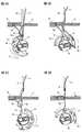
以下、添付図面を参照して、本実施の形態に係る目飛び検出装置を備えたミシンについて説明する。図1は、本実施の形態に係るミシンの斜視図である。図2は、本実施の形態に係る正常時の縫製動作の説明図である。図3は、本実施の形態に係る目飛び発生時の縫製動作の説明図である。なお、本実施の形態に係るミシンは一例に過ぎず、目飛び検出装置を備えたものであれば、どのように構成されてもよい。また、図2においては説明の便宜上、回転釜及びボビンケース以外を省略した釜機構を示している。 Hereinafter, a sewing machine including a skipping detection device according to the present embodiment will be described with reference to the accompanying drawings. FIG. 1 is a perspective view of the sewing machine according to the present embodiment. FIG. 2 is an explanatory diagram of a normal sewing operation according to the present embodiment. FIG. 3 is an explanatory diagram of a sewing operation when a stitch skip occurs according to the present embodiment. The sewing machine according to the present embodiment is merely an example, and may be configured in any manner as long as it includes a skipping detection device. Further, in FIG. 2, for the sake of convenience of explanation, a hook mechanism in which the parts other than the rotary hook and the bobbin case are omitted is shown.
図1に示すように、本実施の形態に係るミシン1は、サイクルミシン等の工業用ミシンであり、主軸に連動した縫い針13の上下動作と回転釜14(図2参照)の回転動作で縫い目を形成する一般的な縫製機構を備えている。ミシンフレーム10には、様々な中継器の他、上糸T1の張力を調節する糸調子器11、上糸T1を引き上げる天秤12が設けられている。上糸ボビン(不図示の糸供給源)から繰り出された上糸T1は、様々な中継器、糸調子器11、天秤12を経て縫い針13に通されている。このように、ミシンフレーム10には、様々な中継器、糸調子器11、天秤12によって上糸ボビンから縫い針13に向かう糸道が形成されている。 As shown in FIG. 1, the
図2Aに示すように、ミシン1のベッド(不図示)の下側には、ボビンケース15がセットされた回転釜14が設置されている。回転釜14は、いわゆる半回転釜であり、ボビンケース15の周囲を時計回り、反時計回りに交互に半回転するように構成されている。回転釜14は半円状の外周部分には、時計回り時の先端側に縫い針13から上糸ループRを捕捉する剣先16が周方向に突出するように形成されている。ボビンケース15には、下糸ボビン(不図示)が収容されており、下糸ボビンから繰り出された下糸T2がボビンケース15に設けられたツノ部17に引き出さている。 As shown in FIG. 2A, a
ミシン1による縫製時には、上糸T1が通された縫い針13が布地Fを貫通することで、布地Fの下側に上糸ループRが形成される。図2Aに示す状態では、上糸ループR内に下糸T2が入り込んでおらず、上糸T1と下糸T2とが交差していない。この状態で、回転釜14が時計回りに回転し始めると、回転釜14の剣先16によって上糸ループRが捕捉される。上糸T1には余分な弛みが生じているため、上糸T1の弛みを無くすようにして回転釜14によって上糸T1が引き込まれる。上糸T1に弛みがある間は、上糸ボビンから新たに上糸T1が繰り出されることがない。 At the time of sewing by the
図2Bに示すように、回転釜14が時計回りにさらに回転すると、縫い針13が布地Fから抜け出され、回転釜14の剣先16によって上糸T1がさらに引き込まれる。回転釜14の剣先16によって上糸ループRが大きく広げられて、上糸ループRの内側に回転釜14が入り込み始める。そして、回転釜14による上糸T1の引き込みによって上糸T1の弛みが無くなると、上糸ボビンから僅かに上糸T1が繰り出される。このとき、糸道の途中に設置された糸調子器11のモータ29(図4参照)が駆動して、糸調子器11によって上糸ボビンから繰り出される上糸T1に張力が付与される。 As shown in FIG. 2B, when the
図2Cに示すように、回転釜14が半回転して上糸ループRの内側を潜り抜けると、回転釜14の剣先16から上糸ループRが解放されて、上糸ボビンからの上糸T1の繰り出しが無くなる。そして、上糸T1と下糸T2が交差した状態で天秤12(図1参照)によって上糸T1が引き上げられて上糸ループRが小さくなる。図2Dに示すように、回転釜14が反時計回りの回転中に上糸T1によって下糸T2が引き上げられ、布地Fが水平方向に送られることで縫い目Sが形成される。そして、天秤12の上動によって上糸ボビンから新たに上糸T1が繰り出されて、図2Aから図2Dまでの動作が繰り返される。 As shown in FIG. 2C, when the
ところで、ミシン1による縫製時には、布地Fに縫い目Sが形成されない目飛びが生じる場合がある。図3Aに示すように、回転釜14が時計回りに回転されて上糸ループRが回転釜14の剣先16で捕捉されないと、剣先16によって上糸T1が引き込まれることがない。よって、図3Bに示すように、回転釜14が半回転しても、上糸ループRの内側を回転釜14が潜り抜けることがなく、上糸T1と下糸T2が交差せずに目飛びが発生する。このような目飛びの検出方法としては、縫い目Sが形成された場合には上糸T1が消費されるため、上糸ボビンから繰り出される上糸T1の移動量を監視する方法が考えられる。 By the way, at the time of sewing by the
しかしながら、上糸T1の伸びや縫いムラ、さらに上糸T1の種類や太さによって上糸T1の移動量にバラツキが生じるため、上糸T1の移動量から目飛びを検出することが困難である。上記したように、正常時には回転釜14による上糸ループRの解放直前の所定区間Aで、上糸T1が引き込まれて上糸T1に張力が生じるようにモータが挙動している(図5B参照)。そこで、本実施の形態に係る目飛び検出では、この所定区間Aにおけるモータの挙動を監視して、上糸T1が引き込まれずに張力が生じない場合に目飛びを検出するようにしている(図5C参照)。 However, since the amount of movement of the upper thread T1 varies depending on the elongation and unevenness of the upper thread T1, and the type and thickness of the upper thread T1, it is difficult to detect the skip from the amount of movement of the upper thread T1. . As described above, in a normal state, the motor behaves so that the upper thread T1 is drawn and tension is generated in the upper thread T1 in the predetermined section A immediately before the upper thread loop R is released by the rotary hook 14 (see FIG. 5B). ). Therefore, in the skip detection according to the present embodiment, the behavior of the motor in the predetermined section A is monitored so that the skip is detected when the upper thread T1 is not drawn and no tension is generated (FIG.
以下、ミシンに搭載された目飛び検出装置について詳細に説明する。図4は、本実施の形態に係る目飛び検出装置の模式図である。なお、図4に示す目飛び検出装置は、一例に過ぎず適宜変更が可能である。また、図4では説明の便宜上、上糸T1の記載を省略している。 Hereinafter, the skipping detection device mounted on the sewing machine will be described in detail. FIG. 4 is a schematic diagram of a skipping detection device according to the present embodiment. Note that the skipping detection device shown in FIG. 4 is merely an example and can be changed as appropriate. Further, in FIG. 4, the upper thread T1 is not shown for convenience of explanation.
図4に示すように、目飛び検出装置21は、上糸T1が巻き掛けられた糸調子器11に、上糸T1の目飛びを検出する検出部22を設けて構成される。糸調子器11は、ミシンフレーム10の貫通孔に筒状の糸調子ケース23を止めネジ(不図示)でネジ止めして取り付けられる。糸調子ケース23の内側には、筒状の糸調子軸24が止めネジ25によって固定されており、糸調子軸24の外周面には糸取りバネ26が巻き付けられている。糸取りバネ26の一端は糸調子軸24の窪みに係止され、糸取りバネ26の他端は折り曲げられて上糸T1が掛けられる糸掛け部27になっている。 As shown in FIG. 4, the stitch skip detection device 21 is configured by providing a
ミシンフレーム10の内面には、ボルト28によってモータ29がネジ止めされている。モータ29の出力軸31は筒状の糸調子軸24の内側に差し込まれ、出力軸31の先端がミシンフレーム10の外面から突出している。出力軸31の先端には、一対の糸調子皿32からなる回転体33が止めネジ34によってネジ止めされている。回転体33には、上糸ボビンから縫い針13に向かう糸道の途中で上糸T1が巻き掛けられている。回転体33は、上糸ボビンからの上糸T1の繰り出し時にモータ29に回転されることで上糸T1に張力を生じさせている。また、モータ29には、出力軸31の回転量を検出するエンコーダ35が取り付けられている。 A
検出部22は、回転釜14による上糸ループR(図2参照)の解放直前の所定区間A(図5B、図5C参照)を監視し、当該所定区間Aにおけるモータ29の挙動から目飛びを検出している。例えば、検出部22は、エンコーダ35から出力されたモータ29の回転位置から上糸T1の移動量(供給量)を推定し、上糸T1の移動がない場合(張力が小さい場合)に回転釜14によって上糸T1が引き込まれていないとして目飛びを検出する。なお、上糸ループRの解放直前の所定区間Aとは、目飛びが発生していなければ、回転釜14による上糸T1の引き込みによって上糸ボビンから上糸T1が繰り出される区間である。 The
また、目飛び検出装置21には、モータ29を駆動制御するモータ制御部36が接続されている。モータ制御部36の制御構成の詳細については後述する。なお、検出部22及びモータ制御部36は、各種処理を実行するプロセッサやメモリ等を含んで構成されている。メモリは、用途に応じてROM(Read Only Memory)、RAM(Random Access Memory)等の一つ又は複数の記憶媒体で構成されている。メモリには、例えば、モータ制御を実行させるプログラムや、ミシン1に目飛び検出を実行させるプログラムが記憶されている。 Further, a
図5及び図6を参照して、検出部による目飛び検出について説明する。図5は、本実施の形態に係る目飛び検出の説明図である。図6は、本実施の形態に係る目飛び検出処理のフローチャートである。なお、図5Aは正常時の天秤曲線及び釜糸取曲線、図5Bは正常時の上糸移動曲線、図5Cは目飛び発生時の上糸移動曲線をそれぞれ示している。また、図5の横軸の上軸角度は、どの時点を原点角度に設定してもよい。ここでは、針棒の最上昇位置である、針棒上死点を原点(0°)としている。以下の説明では、図1から図4の符号を適宜参照しながら説明する。 With reference to FIGS. 5 and 6, the skipping detection by the detection unit will be described. FIG. 5 is an explanatory diagram of skip detection according to the present embodiment. FIG. 6 is a flowchart of the skipping detection process according to the present embodiment. 5A shows a balance curve and a hook thread take-up curve in a normal state, FIG. 5B shows an upper thread movement curve in a normal state, and FIG. 5C shows an upper thread movement curve in the case of skipping. Further, the upper axis angle of the horizontal axis in FIG. 5 may be set to any origin point. Here, the needle bar top dead center, which is the highest position of the needle bar, is defined as the origin (0 °). The following description will be given with reference to FIGS. 1 to 4 as appropriate.
図5A及び図5Bに示すように、正常時の縫製動作では、上軸角度120°において布地Fに縫い針13が刺さり始める。縫い針13が布地Fを貫通すると、布地Fの下方に上糸ループRが形成される(図2A参照)。縫い針13の下動と共に天秤12も下動しているため、上糸T1に弛みが生じている。上軸角度180°付近で縫い針13が上動し始めて、上軸角度200°(−160°)で回転釜14の剣先16に上糸ループRが捕捉される(図2B参照)。このとき、天秤12の下動によって上糸T1に弛みが生じており、上糸T1の弛みをなくすように回転釜14で上糸T1が引き込まれて上糸ループRが広げられる。 As shown in FIGS. 5A and 5B, in the normal sewing operation, the
上軸角度−60°で上糸T1の弛みがなくなって、回転釜14の上糸T1の引き込みによって、上糸ボビン(糸供給源)から新たな上糸T1が繰り出されて供給される。上糸ボビン(糸供給源)から上糸T1が繰り出されると、糸道の途中で糸調子器11のモータ29(図4参照)が駆動して上糸T1に張力が付与される。よって、上糸T1が弛むことなく、回転釜14によって引き込まれる。そして、上軸角度−20°で回転釜14の剣先16から上糸ループRが解放されて、上糸ループRの内側を回転釜14が潜り抜ける(図2C参照)。このように、上糸ループRの解放直前の所定区間A(上軸角度−60°から上軸角度−20°)で、上糸ボビンから新たな上糸T1が供給されている。 When the upper shaft angle is −60 °, the upper yarn T1 is not loosened, and the upper yarn T1 is drawn out and supplied from the upper yarn bobbin (yarn supply source) when the upper yarn T1 of the
上軸角度−20°で回転釜14によって上糸ループRが解放されると、上糸ボビンから上糸T1が繰り出されず上糸T1の供給が停止される。このとき、上糸ループRの解放による上糸T1の弛みがなくなるように天秤12によって上糸T1が引き上げられて縫い目Sが形成される。さらに、天秤12の上動によって上軸角度40°で上糸T1が引き込まれて上糸ボビンから上糸T1が繰り出されている。このように、上糸ループRの解放後の所定区間B(上軸角度40°から上軸角度60°)で、縫い目Sに消費された分だけ上糸ボビン(糸供給源)から新たな上糸T1が供給されている。そして、上糸T1の供給が停止されて、上記の動作が繰り返される。 When the upper thread loop R is released by the
一方で、図5Cに示すように、目飛び発生時の縫製動作では、上軸角度200°(−160°)で回転釜14の剣先16に上糸ループRが捕捉されない(図3A参照)。回転釜14によって上糸T1が引き込まれることがないため、上糸ボビンから上糸T1が繰り出されることもなく、糸調子器11のモータ29が駆動しないため上糸T1に張力が付与されない(図3B参照)。よって、回転釜14による上糸ループRの解放直前の所定区間Aでは、上糸ボビンから上糸T1が供給されることがない。このように、所定区間Aにおける上糸T1の供給量(移動量)の有無、すなわち所定区間Aにおけるモータ29の挙動に応じて、目飛びを検出することが可能になっている。 On the other hand, as shown in FIG. 5C, in the sewing operation when the stitch skip occurs, the upper thread loop R is not captured by the
続いて、図6を参照して、検出部22による目飛び検出の動作フローについて説明する。図6に示すように、回転釜14による上糸ループRの解放直前の所定区間A(上軸角度−40°から上軸角度−20°)におけるモータ29の挙動が監視される(ステップS1)。次に、所定区間Aにおいてエンコーダ35から出力されたモータ29の回転位置に基づいて、上糸T1の移動量が推定されて上糸T1の移動の有無が判定される(ステップS2)。上糸T1の移動があると判定された場合(ステップS2でYes)、目飛びが発生していないとしてステップS1に移行する。 Next, with reference to FIG. 6, an operation flow for detecting skipping by the
上糸T1の移動がないと判定された場合(ステップS2でNo)、モータ29が駆動されておらず、回転釜14による上糸T1の引き込みがないとして目飛びが検出される(ステップS03)。次に、目飛びが検出されると、例えば、音声メッセージや画面表示等によって作業者に警告される(ステップS04)。なお、ステップS04では、目飛び発生後に速やかにミシン1の縫製動作を停止させて、目飛び発生を作業者に知らせるようにしてもよい。このように、所定区間Aで上糸T1が移動しているか否かがモータ29の挙動から認識されて目飛びが検出される。なお、検出部22は、目飛びと共に糸切れを検出して作業者に警告するようにしてもよい。なお、上糸切れ時も、目飛び時と同様に上糸T1の引込みがないため、所定区間Aにおいて上糸T1の供給量(移動量)が無い場合、上糸切れと判断することができる。また、目飛び検出は、通常単発的(偶発的)に発生するが、上糸切れは連続的に発生する。この違いから、目飛びと上糸切れを区別することもできる。 If it is determined that there is no movement of the upper thread T1 (No in step S2), the
本実施の形態では、所定区間Aにおける上糸T1の移動によって目飛びを検出したが、所定区間Aにおけるモータ29(エンコーダ35)の回転位置又は回転位置から導出した回転速度によって目飛びを検出するようにしてもよい。この場合、検出部22は、所定区間Aでエンコーダ35から得られるモータ29の回転位置又は回転速度が上糸T1に張力を生じさせない場合に目飛びを検出する。なお、モータ29の回転位置又は回転速度が上糸T1に張力を生じさせない場合とは、モータ29が回転していない場合だけでなく、上糸T1に張力を発生させない程度にモータ29が回転する場合を含む。 In this embodiment, the skip is detected by the movement of the upper thread T1 in the predetermined section A, but the skip is detected by the rotational position of the motor 29 (encoder 35) in the predetermined section A or the rotational speed derived from the rotational position. You may do it. In this case, the
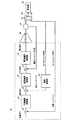
また、モータに対するモータ電流から目飛び検出することも可能である。以下、図7及び図8を参照して、モータ電流による目飛びについて説明する。図7は、本実施の形態に係るモータ制御部の制御ループ図である。図8は、本実施の形態に係るモータ電流による目飛び検出の説明図である。なお、モータ制御の制御ループは、モータ電流が検出可能な構成あればよく、図7に示す構成に限定されない。なお、図8Aは正常時のモータ電流、図8Bは目飛び発生時のモータ電流をそれぞれ示している。 It is also possible to detect skipping from the motor current for the motor. Hereinafter, skipping due to the motor current will be described with reference to FIGS. 7 and 8. FIG. 7 is a control loop diagram of the motor control unit according to the present embodiment. FIG. 8 is an explanatory diagram of skip detection by the motor current according to the present embodiment. The motor control control loop is not limited to the configuration shown in FIG. 7 as long as the motor current can be detected. FIG. 8A shows the motor current when normal, and FIG. 8B shows the motor current when skipping occurs.
図7に示すように、モータ制御部36の制御ループでは、エンコーダ35から出力されたフィードバック信号(モータエンコーダ信号)に基づいて位置、速度、電流の各制御ループが制御される。モータ29には、各制御ループを経て、上糸T1に任意の張力を生じさせるようにモータ電流が通電される。この場合、減算要素e1において、エンコーダ35からフィードバックされたモータ29の回転位置と目標の位置指令とが減算されて位置偏差が算出される。位置偏差は、位置偏差演算部41にて位置ループゲインが乗算されて、速度指令として減算要素e2に出力される。 As shown in FIG. 7, in the control loop of the
減算要素e2において、速度演算部42からのモータ29の回転速度と位置偏差演算部41からの速度指令とが減算されて速度偏差が算出される。速度演算部42では、エンコーダ35からのフィードバック信号に基づいて回転速度が算出されている。速度偏差は、速度偏差演算部44にて速度ループゲインが乗算され、指令電流(トルク指令)として減算要素e3に出力される。減算要素e3において、センサ43で検出された電流と速度偏差演算部44からの指令電流とが減算されて電流偏差(トルク偏差)が算出される。電流偏差は、電流偏差演算部45にて電流ループゲインが乗算されてドライブ部46に出力される。そして、ドライブ部46で増幅されたモータ電流がモータ29に通電される。 In the subtraction element e2, the rotational speed of the
このように、モータ29が回転する場合にはモータ29に対してモータ電流が通電される。したがって、センサ43によって検出される所定区間Aのモータ電流に応じて、検出部22で目飛びを検出することができる。図8Aに示すように、正常時の所定区間Aでは、回転釜14の引き込みによって上糸ボビン(糸供給源)から上糸T1が繰り出されるため、上糸T1に所望の張力を発生させるようにモータ29に対してモータ電流(100[mA]から200[mA])が通電される。モータ29はモータ電流の通電によって上糸T1に張力を生じさせる方向に回転される。この場合、所定区間Aで上糸T1が適切に繰り出されているとして、検出部22によって目飛びが検出されない。 As described above, when the
一方、図8Bに示すように、目飛び検出時の所定区間Aでは、回転釜14で上糸T1が引き込まれることがないため、上糸T1に張力を発生させる必要がなく、モータ29に対して大きなモータ電流が通電されない。モータ電流が上糸T1に張力を生じさせない程度の大きさであるため、所定区間Aで上糸T1が繰り出されていないとして目飛びが検出される。なお、モータ電流が上糸T1に張力を生じさせない場合とは、モータ29にモータ電流が全く通電されない場合だけでなく、上糸T1に張力を発生させない程度にモータ29にモータ電流が通電される場合を含む。 On the other hand, as shown in FIG. 8B, in the predetermined section A when the stitch skip is detected, the upper thread T1 is not pulled in by the
また、検出部22は、正常時のモータ電流と目飛び発生時のモータ電流を比較して、大きな差異がある場合に目飛びを検出するようにしてもよい。この場合、正常時のモータ電流と目飛び発生時のモータ電流とで、所定区間Aの一部の上軸角度(例えば、上軸角度−40°)のモータ電流の大きさを比較してもよいし、所定区間Aのモータ電流の大きさの平均を比較してもよい。また、検出部22は、正常時のモータ電流と目飛び発生時のモータ電流を比較せずに、目飛び発生時のモータ電流が所定の閾値以下の場合に目飛びを検出してもよい。なお、上糸切れ時も、目飛び時と同様に上糸T1が引き込まれず、上糸T1に張力を発生させる必要がないので、モータ29に対して大きなモータ電流が通電されない。このため、所定区間Aで、モータ29に対して大きなモータ電流が通電されない場合、上糸切れであると判断できる。なお、目飛び検出は、通常単発的(偶発的)に発生するが、上糸切れは連続的に発生する。この違いから、目飛びと上糸切れを区別することもできる。 In addition, the
また、上記のモータ制御部36の制御ループにモータ29の出力電圧を検出可能なセンサを設けて、所定区間Aにおけるモータ29の出力電圧から目飛びが検出されてもよい。所定区間Aにおける出力電圧が、上糸T1に張力を生じさせない程度の大きさの場合に検出部22によって目飛びが検出される。なお、出力電圧が上糸T1に張力を生じさせない場合とは、モータ29の出力電圧が全く出力されない場合だけでなく、上糸T1に張力を発生させない程度にモータ29の出力電圧が出力される場合を含む。 Further, a sensor capable of detecting the output voltage of the
また、検出部22は、正常時のモータ29の出力電圧と目飛び発生時のモータ29の出力電圧を比較して、大きな差異がある場合に目飛びを検出するようにしてもよい。この場合、正常時の出力電圧と目飛び発生時の出力電圧とで、所定区間Aの一部の上軸角度(例えば、上軸角度−40°)の出力電圧の大きさを比較してもよいし、所定区間Aの出力電圧の大きさの平均を比較してもよい。また、検出部22は、正常時の出力電圧と目飛び発生時の出力電圧を比較せずに、目飛び発生時の出力電圧が所定の閾値以下の場合に目飛びを検出してもよい。 Further, the
さらに、検出部22は、所定区間Aにおけるモータ29の挙動から目飛びを検出する構成であればよく、例えば、モータ29の回転位置、回転速度、モータ電流、出力電圧、上糸T1の移動量を適宜組み合わせて目飛びを検出してもよい。 Furthermore, the
以上のように、本実施の形態に係る目飛び検出装置21は、回転釜14によって上糸ループRが捕捉された後、回転釜14による上糸ループRの解放直前の所定区間Aにおいてモータ29の挙動が監視されることで目飛びが検出される。モータ29の挙動から上糸T1への張力付与が認識される場合には、回転釜14による上糸T1の引き込みによって上糸ボビンから上糸T1が繰り出されて縫い目Sに消費されたとして目飛びが検出されない。モータ29の挙動から上糸T1への張力付与が認識されない場合には、回転釜14によって上糸ボビン(糸供給源)から上糸T1が引き込まれておらず、縫い目Sが形成されていないとして目飛びが検出される。このように、モータ29の挙動から回転釜14による上糸T1の引き込みが認識されるため、上糸T1の伸びや縫いムラ、さらに上糸の種類や太さの影響を受けることなく高精度に目飛びを検出できる。また、縫いに必要な張力を上糸に生じさせるモータ29で目飛びを検出しているため、縫いに関係のない張力が上糸T1に発生することもない。さらに、目飛びだけでなく上糸T1の糸切れも検出することができる。 As described above, the stitch skip detection device 21 according to the present embodiment has the
なお、本発明は上記実施の形態に限定されず、種々変更して実施することが可能である。上記実施の形態において、添付図面に図示されている大きさや形状などについては、これに限定されず、本発明の効果を発揮する範囲内で適宜変更することが可能である。その他、本発明の目的の範囲を逸脱しない限りにおいて適宜変更して実施することが可能である。 In addition, this invention is not limited to the said embodiment, It can change and implement variously. In the above-described embodiment, the size, shape, and the like illustrated in the accompanying drawings are not limited to this, and can be appropriately changed within a range in which the effect of the present invention is exhibited. In addition, various modifications can be made without departing from the scope of the object of the present invention.
例えば、本実施の形態において、一対の糸調子皿32によって回転体33が形成される構成にしたが、この構成に限定されない。糸調子器11の回転体33は、上糸ボビンから縫い針13に向かう糸道の途中で上糸T1が巻き掛けられる構成であれば、どのように構成されていてもよい。 For example, in this Embodiment, it was set as the structure by which the
また、本実施の形態において、モータ29としてサーボモータを例示して説明したが、この構成に限定されない。モータは、上糸ボビンからの上糸T1の繰り出し時に上糸T1に張力が生じるように回転体33を回転させる構成であればよく、例えば、ステッピングモータでもよい。 In the present embodiment, the servo motor is exemplified as the
また、本実施の形態において、回転釜14として半回転釜を例示して説明したが、この構成に限定されない。回転釜14は、縫い針13で作られる上糸ループRを捕捉可能であればよく、例えば、全回転釜でもよい。 Moreover, in this Embodiment, although the half rotary hook was illustrated and demonstrated as the
以上説明したように、本発明は、糸の伸びや縫いムラの影響を受けることなく、高精度に目飛び検出または上糸切れ検出をすることができるという効果を有し、特に、目飛び検出装置、ミシン、目飛び検出方法及びミシンで用いられるプログラムに有用である。 As described above, the present invention has the effect of being able to detect stitch skipping or upper thread breakage with high accuracy without being affected by thread elongation or sewing unevenness. This is useful for a device, a sewing machine, a skip detection method, and a program used in the sewing machine.
1 ミシン
11 糸調子器
12 天秤
13 縫い針
14 回転釜
21 目飛び検出装置
22 検出部
29 モータ
33 回転体
35 エンコーダ
43 センサ
A 回転釜による上糸ループの解放直前の所定区間
S 縫い目
T1 上糸
T2 下糸DESCRIPTION OF
Claims (7)
Translated fromJapanese糸供給源から前記縫い針に向かう糸道の途中で前記上糸が巻き掛けられた回転体と、
前記糸供給源からの前記上糸の繰り出し時に前記上糸に張力が生じるように前記回転体を回転させるモータと、
前記回転釜による前記上糸ループの解放直前の所定区間を監視し、当該所定区間における前記モータの挙動から目飛びを検出する検出部とを備えることを特徴とする目飛び検出装置。A stitch skip detection device for a sewing machine that captures an upper thread loop made of a sewing needle with a rotary hook and crosses an upper thread and a lower thread to form a seam,
A rotating body around which the upper thread is wound in the middle of a thread path from a thread supply source toward the sewing needle;
A motor that rotates the rotating body so that tension is generated in the upper thread when the upper thread is unwound from the thread supply source;
A skip detection device, comprising: a detection unit that monitors a predetermined section immediately before the upper thread loop is released by the rotary hook and detects a skip from the behavior of the motor in the predetermined section.
前記検出部は、前記所定区間で前記エンコーダの出力から得られる前記モータの回転位置又は回転速度が前記上糸に張力を生じさせない場合に目飛びを検出することを特徴とする請求項1に記載の目飛び検出装置。An encoder for detecting the rotation of the motor;
The said detection part detects a skip when the rotational position or rotational speed of the said motor obtained from the output of the said encoder does not produce tension | tensile_strength in the said upper thread in the said predetermined area. Skip detection device.
前記検出部は、前記所定区間で前記センサによって検出されるモータ電流又は出力電圧が前記上糸に張力を生じさせない場合に目飛びを検出することを特徴とする請求項1から請求項3のいずれかに記載の目飛び検出装置。A sensor for detecting a motor current energized in the motor or an output voltage of the motor;
The detection unit detects a skip when the motor current or the output voltage detected by the sensor in the predetermined section does not cause tension in the upper thread. Crab skip detection device.
前記縫い針の上下動作と前記回転釜の回転動作で縫い目を形成する縫製機構とを備えたことを特徴とするミシン。A skipping detection device according to any one of claims 1 to 4,
A sewing machine comprising: a sewing mechanism that forms a seam by a vertical movement of the sewing needle and a rotational movement of the rotary hook.
糸供給源から前記縫い針に向かう糸道の途中で前記上糸が巻き掛けられた回転体と、前記糸供給源からの前記上糸の繰り出し時に前記上糸に張力が生じるように前記回転体を回転させるモータとを備えた目飛び検出装置に、前記回転釜による前記上糸ループの解放直前の所定区間を監視させ、当該所定区間における前記モータの挙動から目飛びを検出させることを特徴とする目飛び検出方法。A method for detecting stitch skipping in a sewing machine in which an upper thread loop made of a sewing needle is captured by a rotary hook and an upper thread and a lower thread are crossed to form a seam.
A rotating body around which the upper thread is wound in the middle of a yarn path from the thread supply source to the sewing needle, and the rotating body so that tension is generated in the upper thread when the upper thread is fed from the thread supply source. A skip detection device comprising a motor for rotating the needle, monitoring a predetermined section immediately before the release of the upper thread loop by the rotary hook, and detecting a skip from the behavior of the motor in the predetermined section. To detect skipping.
Priority Applications (3)
| Application Number | Priority Date | Filing Date | Title |
|---|---|---|---|
| JP2015085836AJP2016202437A (en) | 2015-04-20 | 2015-04-20 | Stitch skipping detection device, sewing machine, stitch skipping detection method and program |
| CN201610249052.1ACN106065516A (en) | 2015-04-20 | 2016-04-20 | Jump needle detecting device, sewing machine, bouncing pilotage detection method |
| DE102016107262.1ADE102016107262A1 (en) | 2015-04-20 | 2016-04-20 | Sting outlet detecting device, sewing machine and trickle outlet detecting method |
Applications Claiming Priority (1)
| Application Number | Priority Date | Filing Date | Title |
|---|---|---|---|
| JP2015085836AJP2016202437A (en) | 2015-04-20 | 2015-04-20 | Stitch skipping detection device, sewing machine, stitch skipping detection method and program |
Publications (1)
| Publication Number | Publication Date |
|---|---|
| JP2016202437Atrue JP2016202437A (en) | 2016-12-08 |
Family
ID=57043607
Family Applications (1)
| Application Number | Title | Priority Date | Filing Date |
|---|---|---|---|
| JP2015085836APendingJP2016202437A (en) | 2015-04-20 | 2015-04-20 | Stitch skipping detection device, sewing machine, stitch skipping detection method and program |
Country Status (3)
| Country | Link |
|---|---|
| JP (1) | JP2016202437A (en) |
| CN (1) | CN106065516A (en) |
| DE (1) | DE102016107262A1 (en) |
Cited By (4)
| Publication number | Priority date | Publication date | Assignee | Title |
|---|---|---|---|---|
| CN107956051A (en)* | 2017-12-30 | 2018-04-24 | 宁波舒普机电股份有限公司 | A kind of tension disk for automatically adjusting tension force of facial suture |
| DE112017005646T5 (en) | 2017-03-31 | 2019-08-22 | Mitsubishi Electric Corp. | sewing machine |
| CN112636663A (en)* | 2020-11-02 | 2021-04-09 | 上海有个机器人有限公司 | Shaft locking method for servo motor |
| TWI849800B (en)* | 2023-03-15 | 2024-07-21 | 星菱縫機股份有限公司 | Sewing machine with mechanism for preventing skipped stitches |
Families Citing this family (10)
| Publication number | Priority date | Publication date | Assignee | Title |
|---|---|---|---|---|
| CN107099951B (en)* | 2017-05-25 | 2020-05-05 | 杰克缝纫机股份有限公司 | Sewing machine and skip stitch detection device and detection method thereof |
| CN108978062B (en)* | 2017-06-01 | 2020-12-15 | 杰克缝纫机股份有限公司 | A sewing machine and its skipped stitch detection device and detection method |
| CN107988723B (en)* | 2017-12-30 | 2023-07-28 | 舒普智能技术股份有限公司 | Device for automatically adjusting suture tension of sewing machine |
| CN107956050A (en)* | 2017-12-30 | 2018-04-24 | 宁波舒普机电股份有限公司 | A kind of tension disk of automatic tension adjusting |
| JP7075246B2 (en)* | 2018-03-15 | 2022-05-25 | Juki株式会社 | Seam inspection device |
| JP2019166038A (en)* | 2018-03-23 | 2019-10-03 | ブラザー工業株式会社 | sewing machine |
| JP2019166039A (en)* | 2018-03-23 | 2019-10-03 | ブラザー工業株式会社 | sewing machine |
| JP7093225B2 (en)* | 2018-05-21 | 2022-06-29 | Juki株式会社 | Seam inspection device |
| JP2020000731A (en)* | 2018-06-29 | 2020-01-09 | ブラザー工業株式会社 | sewing machine |
| JP7505227B2 (en)* | 2020-03-30 | 2024-06-25 | ブラザー工業株式会社 | Defective judgment device |
Citations (3)
| Publication number | Priority date | Publication date | Assignee | Title |
|---|---|---|---|---|
| JPS63234996A (en)* | 1987-03-24 | 1988-09-30 | 極東産機株式会社 | Thread cutting detector in lock stitch machine for heavy weight fabric |
| JP2013048710A (en)* | 2011-08-31 | 2013-03-14 | Juki Corp | Device for detecting stitch skipping of sewing machine |
| JP5174414B2 (en)* | 2007-10-05 | 2013-04-03 | Juki株式会社 | Sewing thread tension control device |
Family Cites Families (5)
| Publication number | Priority date | Publication date | Assignee | Title |
|---|---|---|---|---|
| US4170951A (en)* | 1978-12-14 | 1979-10-16 | The Singer Company | Skipped stitch detection system |
| JPS6136957A (en) | 1984-07-30 | 1986-02-21 | Nec Corp | Resin sealed type semiconductor integrated circuit |
| JP2808812B2 (en)* | 1990-04-06 | 1998-10-08 | ブラザー工業株式会社 | Thread catching mechanism drive of sewing machine |
| JP2000197786A (en)* | 1999-01-07 | 2000-07-18 | Matsuya R & D:Kk | Stitch skip detection method for sewing machine |
| JP5064539B2 (en)* | 2009-11-13 | 2012-10-31 | 木下精密工業株式会社 | Stitch skipping check device for sewing device |
- 2015
- 2015-04-20JPJP2015085836Apatent/JP2016202437A/enactivePending
- 2016
- 2016-04-20CNCN201610249052.1Apatent/CN106065516A/enactivePending
- 2016-04-20DEDE102016107262.1Apatent/DE102016107262A1/enactivePending
Patent Citations (3)
| Publication number | Priority date | Publication date | Assignee | Title |
|---|---|---|---|---|
| JPS63234996A (en)* | 1987-03-24 | 1988-09-30 | 極東産機株式会社 | Thread cutting detector in lock stitch machine for heavy weight fabric |
| JP5174414B2 (en)* | 2007-10-05 | 2013-04-03 | Juki株式会社 | Sewing thread tension control device |
| JP2013048710A (en)* | 2011-08-31 | 2013-03-14 | Juki Corp | Device for detecting stitch skipping of sewing machine |
Cited By (6)
| Publication number | Priority date | Publication date | Assignee | Title |
|---|---|---|---|---|
| DE112017005646T5 (en) | 2017-03-31 | 2019-08-22 | Mitsubishi Electric Corp. | sewing machine |
| DE112017005646B4 (en) | 2017-03-31 | 2021-10-07 | Mitsubishi Electric Corp. | sewing machine |
| CN107956051A (en)* | 2017-12-30 | 2018-04-24 | 宁波舒普机电股份有限公司 | A kind of tension disk for automatically adjusting tension force of facial suture |
| CN112636663A (en)* | 2020-11-02 | 2021-04-09 | 上海有个机器人有限公司 | Shaft locking method for servo motor |
| CN112636663B (en)* | 2020-11-02 | 2023-09-08 | 上海有个机器人有限公司 | Servo motor shaft locking method |
| TWI849800B (en)* | 2023-03-15 | 2024-07-21 | 星菱縫機股份有限公司 | Sewing machine with mechanism for preventing skipped stitches |
Also Published As
| Publication number | Publication date |
|---|---|
| DE102016107262A1 (en) | 2016-10-20 |
| CN106065516A (en) | 2016-11-02 |
Similar Documents
| Publication | Publication Date | Title |
|---|---|---|
| JP2016202437A (en) | Stitch skipping detection device, sewing machine, stitch skipping detection method and program | |
| JP5174414B2 (en) | Sewing thread tension control device | |
| JP6031380B2 (en) | Double needle sewing machine | |
| JP2009242098A (en) | Automatic winder and operation failure detecting method for automatic winder | |
| JP2007136136A (en) | Sewing thread supply device | |
| US10017890B2 (en) | Sewing machine and control method thereof | |
| JP2007204191A (en) | Yarn take-up device | |
| TWI604099B (en) | Method of and device for controlling fabric take-up in electronic pattern knitting machine | |
| JP5170914B2 (en) | Embroidery machine | |
| CN107099951A (en) | A kind of sewing machine and its bouncing pilotage detection means and detection method | |
| JP2013048710A (en) | Device for detecting stitch skipping of sewing machine | |
| JP6577234B2 (en) | Apparatus and method for influencing the position of a knot between an upper thread and a lower thread when sewing with a sewing machine | |
| US10538869B2 (en) | Sewing machine | |
| CN109311617B (en) | Method for monitoring and controlling the supply of thread to a textile machine and supply device for a textile machine | |
| JP2007210776A (en) | Yarn winding method and yarn winding device | |
| JP5026231B2 (en) | Upper thread clamp device for sewing machine | |
| JP5898753B1 (en) | Sewing failure detection device | |
| JP2021107275A (en) | Yarn winding machine | |
| JP7492077B2 (en) | Disconnection location estimation device and disconnection location estimation method | |
| CN110295463A (en) | Sewing machine | |
| JP5912346B2 (en) | sewing machine | |
| JP7505230B2 (en) | Defect prediction device | |
| CN111485338B (en) | Sewing machine | |
| JPH1157265A (en) | Abnormal thread tension detector for sewing machine | |
| JP4059167B2 (en) | Ribbon winding prevention method and ribbon winding prevention device |
Legal Events
| Date | Code | Title | Description |
|---|---|---|---|
| A621 | Written request for application examination | Free format text:JAPANESE INTERMEDIATE CODE: A621 Effective date:20180404 | |
| A977 | Report on retrieval | Free format text:JAPANESE INTERMEDIATE CODE: A971007 Effective date:20190109 | |
| A131 | Notification of reasons for refusal | Free format text:JAPANESE INTERMEDIATE CODE: A131 Effective date:20190122 | |
| A02 | Decision of refusal | Free format text:JAPANESE INTERMEDIATE CODE: A02 Effective date:20190806 |