JP2016199300A - Drink server - Google Patents
Drink serverDownload PDFInfo
- Publication number
- JP2016199300A JP2016199300AJP2015081517AJP2015081517AJP2016199300AJP 2016199300 AJP2016199300 AJP 2016199300AJP 2015081517 AJP2015081517 AJP 2015081517AJP 2015081517 AJP2015081517 AJP 2015081517AJP 2016199300 AJP2016199300 AJP 2016199300A
- Authority
- JP
- Japan
- Prior art keywords
- tank
- beverage
- bottle
- mode
- water
- Prior art date
- Legal status (The legal status is an assumption and is not a legal conclusion. Google has not performed a legal analysis and makes no representation as to the accuracy of the status listed.)
- Pending
Links
- XLYOFNOQVPJJNP-UHFFFAOYSA-NwaterSubstancesOXLYOFNOQVPJJNP-UHFFFAOYSA-N0.000claimsabstractdescription351
- 238000010438heat treatmentMethods0.000claimsabstractdescription24
- 235000013361beverageNutrition0.000claimsdescription129
- 238000005086pumpingMethods0.000claimsdescription13
- 238000003303reheatingMethods0.000claimsdescription10
- 238000005259measurementMethods0.000claimsdescription6
- 230000003247decreasing effectEffects0.000claims1
- 210000000078clawAnatomy0.000description11
- 238000010586diagramMethods0.000description10
- 238000001816coolingMethods0.000description6
- 239000007788liquidSubstances0.000description3
- 238000004891communicationMethods0.000description2
- 239000003651drinking waterSubstances0.000description2
- 235000020188drinking waterNutrition0.000description2
- 238000000034methodMethods0.000description2
- 230000003287optical effectEffects0.000description2
- 238000007789sealingMethods0.000description2
- 238000000638solvent extractionMethods0.000description2
- 230000003187abdominal effectEffects0.000description1
- 238000013459approachMethods0.000description1
- 238000007599dischargingMethods0.000description1
- 230000005484gravityEffects0.000description1
- 230000010354integrationEffects0.000description1
- 239000000463materialSubstances0.000description1
- NJPPVKZQTLUDBO-UHFFFAOYSA-NnovaluronChemical compoundC1=C(Cl)C(OC(F)(F)C(OC(F)(F)F)F)=CC=C1NC(=O)NC(=O)C1=C(F)C=CC=C1FNJPPVKZQTLUDBO-UHFFFAOYSA-N0.000description1
- 238000003825pressingMethods0.000description1
- 239000002994raw materialSubstances0.000description1
- 239000011347resinSubstances0.000description1
- 229920005989resinPolymers0.000description1
- 230000001954sterilising effectEffects0.000description1
Images


Classifications
- B—PERFORMING OPERATIONS; TRANSPORTING
- B67—OPENING, CLOSING OR CLEANING BOTTLES, JARS OR SIMILAR CONTAINERS; LIQUID HANDLING
- B67D—DISPENSING, DELIVERING OR TRANSFERRING LIQUIDS, NOT OTHERWISE PROVIDED FOR
- B67D1/00—Apparatus or devices for dispensing beverages on draught
- B67D1/08—Details
- B67D1/10—Pump mechanism
- B67D1/101—Pump mechanism of the piston-cylinder type
- B67D1/105—Pump mechanism of the piston-cylinder type for two or more components
- B—PERFORMING OPERATIONS; TRANSPORTING
- B67—OPENING, CLOSING OR CLEANING BOTTLES, JARS OR SIMILAR CONTAINERS; LIQUID HANDLING
- B67D—DISPENSING, DELIVERING OR TRANSFERRING LIQUIDS, NOT OTHERWISE PROVIDED FOR
- B67D1/00—Apparatus or devices for dispensing beverages on draught
- B67D1/08—Details
- B67D1/0801—Details of beverage containers, e.g. casks, kegs
- B67D1/0804—Shape or materials
- B—PERFORMING OPERATIONS; TRANSPORTING
- B67—OPENING, CLOSING OR CLEANING BOTTLES, JARS OR SIMILAR CONTAINERS; LIQUID HANDLING
- B67D—DISPENSING, DELIVERING OR TRANSFERRING LIQUIDS, NOT OTHERWISE PROVIDED FOR
- B67D1/00—Apparatus or devices for dispensing beverages on draught
- B67D1/08—Details
- B67D1/0855—Details concerning the used flowmeter
- B—PERFORMING OPERATIONS; TRANSPORTING
- B67—OPENING, CLOSING OR CLEANING BOTTLES, JARS OR SIMILAR CONTAINERS; LIQUID HANDLING
- B67D—DISPENSING, DELIVERING OR TRANSFERRING LIQUIDS, NOT OTHERWISE PROVIDED FOR
- B67D1/00—Apparatus or devices for dispensing beverages on draught
- B67D1/08—Details
- B67D1/0857—Cooling arrangements
- B—PERFORMING OPERATIONS; TRANSPORTING
- B67—OPENING, CLOSING OR CLEANING BOTTLES, JARS OR SIMILAR CONTAINERS; LIQUID HANDLING
- B67D—DISPENSING, DELIVERING OR TRANSFERRING LIQUIDS, NOT OTHERWISE PROVIDED FOR
- B67D1/00—Apparatus or devices for dispensing beverages on draught
- B67D1/08—Details
- B67D1/0871—Level gauges for beverage storage containers
- B—PERFORMING OPERATIONS; TRANSPORTING
- B67—OPENING, CLOSING OR CLEANING BOTTLES, JARS OR SIMILAR CONTAINERS; LIQUID HANDLING
- B67D—DISPENSING, DELIVERING OR TRANSFERRING LIQUIDS, NOT OTHERWISE PROVIDED FOR
- B67D1/00—Apparatus or devices for dispensing beverages on draught
- B67D1/08—Details
- B67D1/0878—Safety, warning or controlling devices
- B67D1/0882—Devices for controlling the dispensing conditions
- B67D1/0884—Means for controlling the parameters of the state of the liquid to be dispensed, e.g. temperature, pressure
- B—PERFORMING OPERATIONS; TRANSPORTING
- B67—OPENING, CLOSING OR CLEANING BOTTLES, JARS OR SIMILAR CONTAINERS; LIQUID HANDLING
- B67D—DISPENSING, DELIVERING OR TRANSFERRING LIQUIDS, NOT OTHERWISE PROVIDED FOR
- B67D1/00—Apparatus or devices for dispensing beverages on draught
- B67D1/08—Details
- B67D1/0895—Heating arrangements
- B—PERFORMING OPERATIONS; TRANSPORTING
- B67—OPENING, CLOSING OR CLEANING BOTTLES, JARS OR SIMILAR CONTAINERS; LIQUID HANDLING
- B67D—DISPENSING, DELIVERING OR TRANSFERRING LIQUIDS, NOT OTHERWISE PROVIDED FOR
- B67D1/00—Apparatus or devices for dispensing beverages on draught
- B67D1/08—Details
- B67D1/12—Flow or pressure control devices or systems, e.g. valves, gas pressure control, level control in storage containers
- B67D1/1202—Flow control, e.g. for controlling total amount or mixture ratio of liquids to be dispensed
- B67D1/1204—Flow control, e.g. for controlling total amount or mixture ratio of liquids to be dispensed for ratio control purposes
- B67D1/1211—Flow rate sensor
- B67D1/122—Flow rate sensor modulating a pumping rate
Landscapes
- Engineering & Computer Science (AREA)
- Mechanical Engineering (AREA)
- Physics & Mathematics (AREA)
- Chemical & Material Sciences (AREA)
- Analytical Chemistry (AREA)
- Fluid Mechanics (AREA)
- Devices For Dispensing Beverages (AREA)
Abstract
Description
Translated fromJapanese本発明は、ボトルに収容された飲料を供給する飲料サーバに関する。 The present invention relates to a beverage server that supplies beverages contained in bottles.
従来から、ボトルに収容された水等の飲料を供給する飲料サーバが知られている。従来用いられている多くの飲料サーバは、ボトルをウォーターサーバの筐体の上部にセットするタイプの飲料サーバである。この飲料サーバでは、重力を利用して、ボトル内の飲料をウォーターサーバのタンクに落下させる。 2. Description of the Related Art Conventionally, beverage servers that supply beverages such as water contained in bottles are known. Many beverage servers that have been used in the past are types of beverage servers in which bottles are set on top of a water server housing. In this beverage server, the beverage in the bottle is dropped into the tank of the water server using gravity.
しかし、ボトルを筐体の上部にセットすることは、女性や高齢者にとっては容易ではなく、ボトルの交換作業が大変であった。特許文献1は、こうした問題点を解決するために、ボトルを筐体の下部にセットするウォーターサーバを提案している。 However, it is not easy for women and elderly people to set the bottle on the top of the housing, and the bottle replacement work is difficult. Patent Document 1 proposes a water server in which a bottle is set in a lower part of a casing in order to solve such problems.
特許文献2は、バッグインボックス型容器内の飲料水を、温水又は冷水の状態で常時飲用に供するディスペンサの配管系統や冷水タンクにヒータを設けることなく貯溜タンクや配管系統を加熱殺菌する飲料水のディスペンサを提案している。 Patent Document 2 discloses drinking water that heats and sterilizes a storage tank or piping system without providing a heater in a piping system or cold water tank of a dispenser that always supplies drinking water in a bag-in-box type container in the state of hot water or cold water. Has proposed a dispenser.
飲料サーバは、ユーザの使い勝手を向上するための様々な工夫がなされている。本発明は、従来の飲料サーバよりも使い勝手の良い飲料サーバを提供する。 The drink server is devised in various ways to improve the user-friendliness. The present invention provides a beverage server that is easier to use than conventional beverage servers.
本発明の飲料サーバは、交換可能なボトルに入った飲料を貯留する第1のタンク及び第2のタンクと、前記第2のタンクに貯留された飲料を加熱する加熱装置と、前記第1のタンクと前記第2のタンクとを循環する循環管路と、前記循環管路上に設けられ、前記飲料を循環させるポンプとを備え、前記ポンプを間欠的に駆動させて、前記第1のタンクと前記第2のタンクとの間で飲料を循環させる。このように第2のタンク内の加熱された飲料を第1のタンクに循環させることで第1のタンクを殺菌することができる。この際、ポンプを間欠的に駆動させることにより、ポンプの長寿命化を図ることができる。 The beverage server of the present invention includes a first tank and a second tank for storing beverages in replaceable bottles, a heating device for heating beverages stored in the second tank, and the first tank A circulation line that circulates between the tank and the second tank; and a pump that is provided on the circulation line and circulates the beverage. The pump is intermittently driven, and the first tank A beverage is circulated between the second tank. In this way, the first tank can be sterilized by circulating the heated beverage in the second tank to the first tank. At this time, it is possible to extend the life of the pump by driving the pump intermittently.
本発明の飲料サーバにおいて、前記循環管路は、飲料が前記第1のタンクから前記第2のタンクに向かう第1の管路と、飲料が前記第2のタンクから前記第1のタンクに向かう第2の管路とを有し、前記第2の管路の端部は、前記第1のタンクの下部に接続していてもよい。この構成により、第1のタンクに入った加熱された飲料は第1のタンクの上方に対流していくが、第1のタンクの下部を効率的に温めることができる。 In the beverage server of the present invention, the circulation conduit includes a first conduit from which the beverage goes from the first tank to the second tank, and a beverage from the second tank to the first tank. A second pipe line, and an end of the second pipe line may be connected to a lower part of the first tank. With this configuration, the heated beverage that has entered the first tank convects above the first tank, but the lower portion of the first tank can be efficiently heated.
本発明の飲料サーバは、前記第1のタンク内に設けられた水平な板を有し、前記板に前記第1の管路の端部が接続していてもよい。水平な板により第1のタンクの上下が緩やかに仕切られるが、水平な板の上にある飲料を第2のタンクに向けて送り出すので、第1のタンク内の飲料の温度を効率的に温めることができる。 The beverage server of the present invention may have a horizontal plate provided in the first tank, and an end of the first conduit may be connected to the plate. The upper and lower sides of the first tank are gently partitioned by the horizontal plate, but since the beverage on the horizontal plate is sent out toward the second tank, the temperature of the beverage in the first tank is efficiently warmed. be able to.
本発明の飲料サーバは、前記第1のタンク及び前記第2のタンクの下方に、前記ボトルを設置する支持台と、前記第1のタンクと前記ボトルとを接続する供給管路と、前記供給管路上に設けられ、前記ボトルから前記第1の飲料サーバに飲料を汲み上げるための開放型の汲上げ用ポンプとを備えてもよい。開放型の汲上げ用ポンプを用いることにより、第1のタンクの温度上昇に伴って第1のタンクの内圧が上昇したときに、第1のタンク内の空気をボトルへ戻すことにより、第1のタンクの内圧の上昇を軽減できる。 The beverage server according to the present invention includes a support base for installing the bottle, a supply conduit for connecting the first tank and the bottle, and the supply below the first tank and the second tank. An open-type pump for pumping may be provided on the pipeline for pumping a beverage from the bottle to the first beverage server. By using an open-type pump for pumping, when the internal pressure of the first tank rises as the temperature of the first tank rises, the air in the first tank is returned to the bottle. The increase in internal pressure of the tank can be reduced.
本発明の飲料サーバは、前記第1のタンク及び前記第2のタンクの下方に、前記ボトルを設置する支持台と、前記第1のタンクと前記ボトルとを接続する供給管路と、前記循環管路の一部と前記供給管路の一部は共有の管路となっており、当該共有の管路を、前記循環管路として用いるか前記供給管路として用いるかを切り替える切替え弁とを備え、前記ポンプは、前記共有の管路に設けられた開放型のポンプであり、前記切替え弁は、前記ポンプを駆動させているときは、前記共有の管路を前記循環管路につなぎ、前記ポンプを停止させているときは、前記共有の管路を前記供給管路につないでもよい。このように開放型のポンプを停止させているときには共有の管路を供給管路につなぐことにより、供給管路を通じて、第1のタンク内の空気をボトル側に逃がすことができる。したがって、第1のタンクの温度上昇に伴う第1のタンクの内圧上昇を軽減することができる。 The beverage server of the present invention includes a support base for installing the bottle, a supply conduit for connecting the first tank and the bottle, and the circulation below the first tank and the second tank. A part of the pipeline and a part of the supply pipeline are shared pipelines, and a switching valve that switches whether the shared pipeline is used as the circulation pipeline or the supply pipeline. The pump is an open-type pump provided in the shared pipeline, and the switching valve connects the shared pipeline to the circulation pipeline when driving the pump, When the pump is stopped, the shared pipeline may be connected to the supply pipeline. Thus, when the open pump is stopped, the air in the first tank can be released to the bottle side through the supply line by connecting the common line to the supply line. Therefore, the increase in the internal pressure of the first tank accompanying the temperature increase of the first tank can be reduced.
本発明の飲料サーバは、前記供給管路上の前記共有の管路ではない場所に設けられた流量計を備えてもよい。供給管路には、第2のタンクで加熱された飲料が通過することはないので、流量計を熱から保護することができる。 The beverage server of the present invention may include a flow meter provided at a location that is not the shared pipeline on the supply pipeline. Since the beverage heated in the second tank does not pass through the supply line, the flow meter can be protected from heat.
本発明の飲料サーバにおいて、前記ボトルは、飲料の流出に従って変形するボトルであってもよい。この構成により、第1のタンクからボトルへと空気が流入した場合にはボトルが膨らむ余地があるので、第1のタンクの内圧上昇を効果的に軽減できる。 In the beverage server of the present invention, the bottle may be a bottle that is deformed in accordance with the outflow of the beverage. With this configuration, when the air flows from the first tank into the bottle, there is room for the bottle to swell, so that an increase in the internal pressure of the first tank can be effectively reduced.
本発明の飲料サーバは、前記第1のタンク内の飲料の温度を計測する温度センサを備え、前記循環管路を通じて前記第1のタンクと前記第2のタンクとの間で飲料を循環させた後、前記温度センサにて計測した温度が所定の閾値以下となるまで、前記第1のタンクから飲料の取り出しを停止してもよい。この構成により、第1のタンクから加熱された飲料を誤って取り出してしまうことがなく、やけどを未然に防止することができる。 The beverage server of the present invention includes a temperature sensor that measures the temperature of the beverage in the first tank, and circulates the beverage between the first tank and the second tank through the circulation pipe. Thereafter, the takeout of the beverage from the first tank may be stopped until the temperature measured by the temperature sensor becomes equal to or lower than a predetermined threshold. With this configuration, the heated beverage is not accidentally taken out from the first tank, and burns can be prevented in advance.
本発明の飲料サーバは、交換可能なボトルに入った飲料を貯留する第1のタンク及び第2のタンクと、前記第2のタンクに貯留された飲料を加熱する加熱装置と、前記第1のタンクに接続された出水管路上に配置された第1の弁と、前記第2のタンクに接続された出水管路上に配置された第2の弁と、飲料の注出を指示する注出ボタンと、前記注出ボタンを押下されたときに前記第1の弁を開く第1のモードと、前記注出ボタンを押下されたときに前記第2の弁を開く第2のモードとを切り替える切替ボタンとを備える。この構成により、一つの注出口から加熱されていない飲料と加熱された飲料の両方を注出することができる。 The beverage server of the present invention includes a first tank and a second tank for storing beverages in replaceable bottles, a heating device for heating beverages stored in the second tank, and the first tank A first valve disposed on a water discharge line connected to the tank; a second valve disposed on a water discharge line connected to the second tank; and a dispensing button for instructing a beverage to be dispensed Switching between a first mode in which the first valve is opened when the dispensing button is pressed and a second mode in which the second valve is opened when the dispensing button is pressed And a button. With this configuration, it is possible to pour both unheated beverages and heated beverages from one spout.
本発明の飲料サーバは、前記第1のモードにおいて前記切替ボタンが操作されたときに前記第1のモードから前記第2のモードに切り替え、前記第2のモードにおいて前記注出ボタンの押下がなされない状態が所定時間継続したときに前記第2のモードから前記第1のモードに切り替えてもよい。このように注出ボタンの押下がなされない状態が所定時間継続したときに第1のモードに戻すことにより、加熱された飲料をうっかり注出することを防止できる。 The beverage server according to the present invention switches from the first mode to the second mode when the switching button is operated in the first mode, and the dispensing button is not pressed in the second mode. When the state that is not performed continues for a predetermined time, the second mode may be switched to the first mode. Thus, by returning to the first mode when the state in which the dispensing button is not pressed continues for a predetermined time, it is possible to prevent the heated beverage from being inadvertently dispensed.
本発明の飲料サーバは、前記第1のモードから前記第2のモードへの切り替え時、または、前記第2のモードから前記第1のモードへの切り替え時に、報知音を発する報知音出力部を備えてもよい。また、前記第2のモードであることを示す表示灯を備えてもよい。これにより、加熱された飲料が注出されるモードかどうかをユーザに注意を喚起し、やけどの危険を低減できる。 The beverage server of the present invention includes a notification sound output unit that emits a notification sound at the time of switching from the first mode to the second mode or at the time of switching from the second mode to the first mode. You may prepare. Moreover, you may provide the indicator lamp which shows that it is the said 2nd mode. Thereby, it is possible to alert the user whether or not the heated beverage is in a mode of being dispensed, and to reduce the risk of burns.
本発明の飲料サーバは、交換可能なボトルに入った飲料を貯留するタンクと、前記タンクの下方に、前記ボトルを設置する支持台と、前記タンクとボトルとを接続する供給管路と、前記供給管路上に設けられ、前記ボトルから前記タンクに飲料を汲み上げるためのポンプと、前記供給管路上に設けられた流量計と、前記流量計にて計測した流量に基づいて、前記供給管路を通じて汲み上げた飲料の量を計測する計測部と、前記計測結果に基づいて前記ボトル内の残量に関する情報を表示する表示部とを備える。この構成により、ボトルが目視できない場合であっても、ユーザは、ボトル内の飲料の残量を把握できる。 The beverage server of the present invention includes a tank for storing beverages in replaceable bottles, a support base for installing the bottles below the tanks, a supply line for connecting the tanks and the bottles, A pump for pumping beverage from the bottle into the tank; a flow meter provided on the supply pipeline; and a flow rate measured by the flow meter, through the supply pipeline. A measurement unit that measures the amount of the beverage that has been pumped, and a display unit that displays information related to the remaining amount in the bottle based on the measurement result. With this configuration, even when the bottle is not visible, the user can grasp the remaining amount of beverage in the bottle.
本発明の飲料サーバにおいて、前記計測部は、前記流量計による計測した流量が所定時間に亘って所定の閾値以下の場合に、汲み上げ量をリセットしてもよい。これにより、新たにボトルがセットされたときには適切にボトル残量を計算することができる。 In the beverage server of the present invention, the measurement unit may reset the pumping amount when the flow rate measured by the flowmeter is equal to or less than a predetermined threshold over a predetermined time. Thereby, when a bottle is newly set, the remaining amount of the bottle can be calculated appropriately.
本発明の飲料サーバは、交換可能なボトルに入った飲料を貯留するタンクと、前記タンクに貯留された飲料を加熱する加熱装置と、前記タンク内の飲料の再加熱を指示する再加熱ボタンとを備える。この構成により、特に高温の飲料(例えば90℃)を必要とする場合に加熱を行えばよいので、普段は、若干低めの温度設定(例えば80〜85℃)とすることができ、タンクの温度を保持するためのエネルギーを節約できる。 The beverage server of the present invention includes a tank for storing beverages contained in replaceable bottles, a heating device for heating beverages stored in the tanks, and a reheating button for instructing reheating of beverages in the tanks. Is provided. With this configuration, heating may be performed particularly when a high-temperature beverage (for example, 90 ° C.) is required. Usually, the temperature can be set to a slightly lower temperature (for example, 80 to 85 ° C.). Can save energy for holding.
本発明の飲料サーバは、前記タンクに貯留された飲料の再加熱中であることを表示する表示灯を備えてもよい。また、前記タンクの飲料の温度を計測する温度センサを備え、前記表示灯は、前記タンク内の飲料の温度が通常の保持温度より高い所定の温度範囲内にあるときに点灯または点滅させてもよい。これにより、タンクの飲料が再加熱中であるか否か、その温度を把握することができる。なお、「通常の保持温度」とは、再加熱を行っていないときのタンクの保持温度範囲を意味する。 The beverage server of the present invention may include an indicator lamp that displays that the beverage stored in the tank is being reheated. In addition, a temperature sensor for measuring the temperature of the beverage in the tank is provided, and the indicator lamp may be lit or blinked when the temperature of the beverage in the tank is within a predetermined temperature range higher than a normal holding temperature. Good. Thereby, it is possible to grasp whether or not the beverage in the tank is being reheated. The “normal holding temperature” means a holding temperature range of the tank when reheating is not performed.
本発明の飲料サーバは、交換可能なボトルに入った飲料を貯留する飲料タンクと、前記飲料タンクの下方に、前記ボトルを設置する支持台と、前記支持台に立設され、倒立された前記ボトルのキャップを突き刺す受水棒と、前記支持台をスライド可能に載置する底面とを備え、前記支持台を筐体の外に引き出した状態で係合する係合部が、前記支持台と前記台座のそれぞれに設けられている。前記係合部は、前記支持台が前記台座に対して垂直方向に移動することを制限してもよい。この構成により、ボトルを受水棒から引き抜くときに、支持台の浮き上がりを防止できる。 The beverage server according to the present invention includes a beverage tank that stores a beverage in a replaceable bottle, a support base that installs the bottle below the beverage tank, and the inverted stand that is erected on the support base. A water receiving rod that pierces the cap of the bottle; and a bottom surface on which the support base is slidably mounted, and an engaging portion that engages in a state in which the support base is pulled out of the housing. Each of the pedestals is provided. The engaging portion may limit movement of the support base in a direction perpendicular to the pedestal. With this configuration, it is possible to prevent the support base from being lifted when the bottle is pulled out from the water receiving rod.
本発明の飲料サーバは、交換可能なボトルに入った飲料を貯留する飲料タンクと、飲料の注出を指示する注出ボタンと、前記注出ボタンによる操作を無効にするボタンとを備える。これにより、乳幼児等によりいたずらを防止することができる。 The beverage server of the present invention includes a beverage tank that stores beverages in replaceable bottles, a dispensing button that instructs dispensing of the beverage, and a button that invalidates the operation by the dispensing button. Thereby, mischief by infants etc. can be prevented.
本発明の飲料サーバは、従来の飲料サーバに比べて使い勝手が良い。 The beverage server of the present invention is more convenient than conventional beverage servers.
以下、本発明の実施の形態の飲料サーバについて、図面を参照しながら説明する。以下では、ボトルに入った水を供給するウォーターサーバを例として説明するが、本発明の飲料サーバは、水だけではなく、各種の飲料を供給するために適用することができる。 Hereinafter, a beverage server according to an embodiment of the present invention will be described with reference to the drawings. Hereinafter, a water server that supplies water in a bottle will be described as an example, but the beverage server of the present invention can be applied to supply not only water but also various beverages.
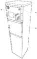
図1は、実施の形態のウォーターサーバ1の斜視図である。ウォーターサーバ1は、横幅が約30cm、奥行きが約38.6cm、高さが約115cmの略直方体の筐体10を有する。 FIG. 1 is a perspective view of a water server 1 according to an embodiment. The water server 1 has a substantially
筐体10は、その前面の上の方の操作しやすい位置に操作パネル11を有している。操作パネル11は、ウォーターサーバ1の前に立ったユーザが見やすいように、斜め上方向に向けられている。操作パネル11の下には、ウォーターサーバ1から注出された水を入れるコップ等を置くトレイ12を有している。操作パネル11の一番下に設けられた注出ボタン33(図2参照)を押すことにより、注出ボタン33を押している間、ウォーターサーバ1は、注出口13から出水する。 The
図2は、操作パネル11を示す図である。操作パネル11には、上述した注出ボタン33に加えて、種々の表示灯およびボタンが設けられている。具体的には、ウォーターサーバ1の状態を示す表示灯として、給水表示灯21と、温水表示灯22と、冷水表示灯23と、エコモード表示灯24とを備えている。また、操作ボタンとして、クリーンシステムボタン26と、弱冷水モードボタン28と、再加熱ボタン30と、HOTボタン32とが設けられており、さらに、これらの各ボタンと同じ場所に各ボタンによる機能の動作状態を示す表示灯25、27、29、31を有している。また、操作パネル11には、給水表示灯21の上に、周囲の明るさを検知する光センサ20が設けられている。操作パネル11に備えられた各ボタン及び表示灯の詳細な機能については後述する。図1に示すように、ウォーターサーバ1は、前面のトレイ12の下方に、筐体10内にボトル60をセットする際に開く扉14を有している。 FIG. 2 is a diagram showing the
図3は、ウォーターサーバ1を斜め後ろから見た斜視図である。ウォーターサーバ1の背面の上方には、チャイルドロックスイッチ15を有している。チャイルドロックスイッチ15は、操作パネル11による操作を無効にするためのスイッチである。操作パネル11は、チャイルドロック15が操作されて無効になった状態であることを、その表示状態によって分かるようにする。本実施の形態では、給水表示灯21のみ点灯を継続し、その他の表示灯を消灯する。なお、操作パネルの状態が無効であることが分かればよいので、その表示方法は本実施の形態の方法に限られず、例えば、チャイルドロック専用の表示灯を設けてもよい。チャイルドロックスイッチ15のある場所は、筐体10の下面からおよそ1mの位置であり、乳幼児の手が届かない場所である。また、ウォーターサーバ1の背面上方のチャイルドスイッチ15の反対側には、ウォーターサーバ1の電源スイッチ16を有している。製品出荷時には電源スイッチ16の上にシールを取り付けておいてもよい。これにより、温水タンク50を誤って空焚きする等の不都合を防止できる。なお、筐体10の裏面にあるチャイルドロック15は、目視することなく手探りで操作できるようにするため、その形状を工夫している。具体的には、チャイルドロック15の形状を小さく細長くし、電源スイッチ16と容易に区別できるようにしている。 FIG. 3 is a perspective view of the water server 1 as viewed obliquely from behind. A
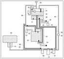
図4は、実施の形態のウォーターサーバ1の配管や弁などを示す構成を示す図である。ウォーターサーバ1の筐体10の内部には、上方から、ボトル60から汲み上げた水を貯留する冷水タンク40及び温水タンク50が設けられている。筐体10内において、冷水タンク40及び温水タンク50は注出口13より高い位置に配置されている。 FIG. 4 is a diagram illustrating a configuration showing piping, valves, and the like of the water server 1 according to the embodiment. Inside the
冷水タンク40には温度センサ41と図示していない冷却装置が設けられており、冷水タンク40内の水温が5〜10℃に保持される。また温水タンク50には温度センサ51と図示していない加熱装置が設けられており、温水タンク50内の水温が80〜85℃に保持される。 The
温水タンク50の下にある支持台80(図6参照)にボトル60がセットされる。本実施の形態のウォーターサーバ1は、ボトル60をセットする位置が筐体10の下部であり、ボトル60を高く持ち上げる必要がないので、女性や高齢者であっても容易にボトル60をセットすることができる。なお、図4においては、ボトル60が、冷水タンク40及び温水タンク50と略同じ大きさで描かれているが、実際にはボトル60の方が大きい。 The
ボトル60と冷水タンク40とは、供給管90によって接続されている。ボトル60の取水口を下にして設置される。ボトル60内の水は、ボトル60のキャップに突き刺された受水棒81を通じて、供給管90に流れ込む。冷水タンク40は、ボトル60よりも高い場所にあるので、供給管90には、ボトル60内の水を冷水タンク40に汲み上げるためのポンプ91を備えている。図4において、矢印は、通常運転中の水の流れを示している。 The
ボトル60と温水タンク50とは直接接続されておらず、温水タンク50には、冷水タンク40を通じて水が供給される。すなわち、冷水タンク40と温水タンク50とは、第1の管93によって接続されている。冷水タンク40側の第1の管93の入口は、冷水タンク40の底部ではなく、所定の高さに配置された円盤46の中央に設けられている。これにより、冷水タンク40内の円盤46の高さまで水が満たされたときに初めて温水タンク50に水が供給される。また、この円盤46は、後述するとおり、円盤46の上下において冷水タンク40に蓄えられた水を緩やかに仕切る役割を有する。本実施の形態では、冷水タンク40が円筒形状を有しているため、冷水タンク40の上下を緩やかに仕切る板として、円形の円盤46を用いているが、その形状は必ずしも円形でなくてもよい。 The
また、冷水タンク40と温水タンク50とは、温水タンク50から冷水タンク40へと水を戻す第2の管94によって接続されている。第1の管93と第2の管94は、冷水タンク40と温水タンク50との管で水を循環させる循環管路を構成している。第1の管93は、冷水タンク40から温水タンク50へ水を供給する役割を有すると共に、冷水タンク40と温水タンク50との管で水を循環させる循環管路としての役割を有している。第2の管94は、冷水タンク40に温水タンク50内の熱湯を供給して、冷水タンク40を殺菌消毒するときに用いられる。 The
第2の管94の一部は、ボトル60から冷水タンク40へ水を汲み上げる供給管90の一部と共有している。説明の便宜上、管の共有部分95を「共有管」という。この共有管95は、(A)ボトル60から冷水タンク40へ汲み上げる水を流す経路、(B)温水タンク50から冷水タンク40へと水を流す経路のいずれとしても用いることができ、共有管95の両端部に設けた切替電磁弁96,97によって、共有管95を(A)(B)のいずれの経路として用いるかを切り替える。図5は、切替電磁弁96,97により、経路(B)に切り替えて、冷水タンク40と温水タンク50との間で水を循環させるときの水の流れを示す。 A part of the
ボトル60から冷水タンク40に水を汲み上げるためのポンプ91は、この共有管95に設けられている。このように共有管95にポンプ91を配置することにより、ボトル60から冷水タンク40から水を汲み上げるためのポンプ91を、冷水タンク40と温水タンク50との間の水の循環にも用いることができる。本実施の形態で用いられるポンプ91は、羽根車に側板とよばれる囲い板を持たない開放型のポンプ91である。 A
また、供給管90には、ボトル60から冷水タンク40に汲み上げる水の流量を計測する流量計92が設けられている。流量計92にて計測した流量に基づいて、供給管90を通じて汲み上げた飲料の量を計算し、ボトル60に残っている水の量を求めることができる。従来はボトル60をウォーターサーバの上に載置していたので、ボトル60に残っている水量を目視することができたが、本実施の形態では、ボトル60は筐体10の中に収容されているので目視することができない。そこで、流量計92で求めた流量に基づいてボトル60に残った水の量を計算し、給水表示灯21に残量に応じた表示を行うことにより、ユーザに残量を知らせる。 The
冷水タンク40及び温水タンク50は、それぞれ出水管42,52を有している。これらの2つの出水管42,52は筐体10の前面の注出口13につながっている。出水管42,52には、それぞれ出水電磁弁43,53が設けられており、出水電磁弁43,53を開くことにより注出口13から出水するが、注出ボタン33を押したときに、冷水タンク40と温水タンク50のいずれの出水電磁弁43,53を開くかは、HOTボタン32により切り替えられる。なお、出水電磁弁43、53を開いたときに注出口13から出水するのは、出水電磁弁43、53を開くのと同時に、ポンプ91によってボトル60の水を冷水タンク40に汲み上げるからである。すなわち、ウォーターサーバ1は、注出ボタン33が押されている間、出水電磁弁43、53のいずれかを開くと共に、ポンプ91を駆動して水の汲み上げを行う。 The
冷水タンク40の上部には、フロート弁44によって開閉する空気口が形成されている。これにより、冷水タンク40に水を入れる初期入水時においては、冷水タンク40内の空気を外部に逃がして入水することができる。また、温水タンク50の上部と冷水タンク40の上部は、排気管98によって接続されている。これによって、温水タンク50内の空気は、排気管98と冷水タンク40を介して、冷水タンク40の空気口から外部に出ていくので、初期入水時に温水タンク50へ水を入れることができる。なお、図4の例では、排気管98は第2の管94から分岐しているが、必ずしも第2の管94から分岐させる必要はなく、温水タンク50の上部と直接つながっていてもよい。 An air opening that is opened and closed by a float valve 44 is formed in the upper part of the
空気口には、フロート弁44が取り付けられており、冷水タンク40内の水位が所定の水位になると、空気口が閉塞される。この構成により、冷水タンク40は、ボトル60から汲み上げた水が所定の水位になった状態では、密閉状態となる。また、空気口には、逆止弁45が設けられており、外部からの空気の流入を防止している。これにより、例えば、水面変化(波打ち等)があったときにも、冷水タンク40内への空気流入を防止できる。 A float valve 44 is attached to the air port. When the water level in the
冷水タンク40は、その底面に冷水タンク40内の水を抜くためのドレン48を有している。温水タンク50内の水を抜くためのドレン54は、第1の管93の温水タンク50より低い位置に設けられている。また、ドレン48,54からスムーズに水が抜けるように、水を抜くときに冷水タンク40内に空気を供給するドレン49が冷水タンク40の上面に設けられている。 The
図9は、ウォーターサーバ1にセットされるボトル60を示す図である。このボトル60は、上から見てほぼ正方形状で、下方に位置する底部61、側面を取り囲む胴部62、上面を覆う肩部64、肩部64の中心から円柱状に突出する首部63から構成され、首部63には密封のためのキャップ69が取り付けられている。ボトル60には12リットルの水を入れることができる。底部61は、文字通りボトル60の底となる部分であり、単純な板状で、その外縁から壁状の胴部62が上方に突出している。胴部62は、底部61寄りの裾絞り部67と、この上の蛇腹部65で構成され、裾絞り部67は、底部61に近づくに連れて断面が絞り込まれている。また蛇腹部65は、複数の蛇腹66が上下に積層された構造で、個々の蛇腹66が押し潰されることで、蛇腹部65の高さが減少する。 FIG. 9 is a diagram illustrating the
図10(a)は水Wの約半分が消費された段階のボトル60を示す図、図10(b)はほぼ全量の水Wが消費された段階のボトル60を示す図である。図10(a)では液面が蛇腹部65のほぼ中央に達しており、液面よりも上に位置する蛇腹66は、大気圧によって押し潰されており、さらに底部61も蛇腹部65の内部に引き込まれている。その後、液体Wの消費と共に蛇腹部66がさらに潰れていき、最終的には図10(b)のように蛇腹部65が完全に押し潰され、且つ蛇腹部65の内部に底部21や裾絞り部67が引き込まれており、容積が大きく減少する。なお、図10(a)において、73は、連通孔71を塞ぐために嵌め込まれた中栓である。 FIG. 10A is a diagram showing the
図9に戻って、ボトル60の構成を説明する。胴部72の上には、ボトル60を覆う肩部64が形成されている。肩部64は、首部63に向けて突出する角錐状になっており、その強度を向上するため、複数のリブ68が形成されている。なお底部61から首部63までのボトル60全体は、PET樹脂を素材として一体的に製造されているが、キャップ69は密封性を確保する必要があり、他の素材を使用している。キャップ69の側面には割り溝70が形成されており、これを引き裂くことで、首部63からキャップ69だけを離脱できる構造になっている。 Returning to FIG. 9, the configuration of the
図6(a)はウォーターサーバ1にボトル60がセットされた構成を示す図である。ボトル60は、支持台80の上に倒立した状態でセットされる。図6(b)は、支持台80を筐体10の外部に引き出した様子を示す図である。支持台80は、筐体10の底面17に対してスライド可能な構成を有している。これにより、支持台80を筐体10の外部に引き出した状態でボトル60をセットすることができるので、支持台80の上にボトル60をセットしやすい。 FIG. 6A is a diagram showing a configuration in which the
図7(a)は、支持台80及び筐体底面17の断面斜視図である。筐体底面17に設けられたガイドレール18に案内されて支持台80は一方向にスライドする。筐体底面17には爪部19があり、支持台80の下部には爪部19と係合する爪部82が設けられている。図7(b)に示すように、支持台80が筐体10外部にスライドされると、支持台80に設けられた爪部82が筐体10底面17の爪部19に引っかかり、支持台80がそれ以上、外側にスライドしないように停止される。 FIG. 7A is a cross-sectional perspective view of the
図7(c)は、爪部19と爪部82との係合状態を拡大して示した図である。爪部19が爪部82よりも上に来るので、爪部19によって支持台80が上に浮き上がるのを防止する。これにより、空になったボトル60を支持台80から持ち上げる際に、受水棒81とボトル60との摩擦力によって支持台80が上方に引っ張られて浮き上がるのを防止できる。 FIG. 7C is an enlarged view showing the engagement state between the
図8は、ウォーターサーバ1の制御部100を説明するための図である。ウォーターサーバ1は、各種状態を検知するセンサとして、冷水タンク40内の水位を検知する水位センサ47と、冷水タンク40の温度センサ41と、温水タンク50の温度センサ51と、供給管90を通る水の量を計測する流量計92を有している。制御部100は、これらのセンサでの検知した状態と操作パネル11での操作状態に従って、ポンプ91、出水電磁弁43,53と、切替電磁弁96,97、冷却装置101、加熱装置102、アラーム103等の制御を行う。以下、ウォーターサーバ1の各種の機能について詳しく説明する。 FIG. 8 is a diagram for explaining the
[ウォーターサーバ1の機能]
給水表示灯21は、ボトル60内の残量を検知し、残量に関する情報を表示する機能を有する。ボトル60内の残水量は、上述したとおり、流量計92によって計測した流量を積算することによって求めることができる。なお、流量の積算は、制御部100が行う。給水表示灯21は、ボトル60の残量が4リットル以上ある場合には青色表示し、4リットル以下になった場合には黄色表示し、空になった場合には赤色を点滅する。ここでは、ボトル60の残量を基準に説明しているが、実際には、ボトル60に最初12リットルの水が入っていることから、汲み上げた水量の積算が8リットル以上になったときに、制御部100は、ボトル60の残量が4リットル以下になったと判断する。[Function of water server 1]
The water
なお、ボトル60が空になったこと(つまり、ボトル60内の水の残量がゼロになったこと)は、ポンプ91での汲み上げを行っても、流量計92が3秒以上流量を感知しない場合に検知することとする。なお、ボトル60が空になったことを検知したときには、流量の積算をリセットする。ここでは、給水表示灯21の点灯・点滅の一例を示したが、給水表示灯21の表示タイミング、表示色、点灯または点滅の態様は、ここで説明した例に限らず、ボトル60の容量などに応じて適宜設定することができる。 Note that the fact that the
温水表示灯22は、加熱装置102に通電している場合に点灯する。温水タンク50内の水温は80〜85℃に保たれるが、水温が80℃に達していない場合には、温水表示灯22を点滅させ、加熱中であることを示す。 The hot
冷水表示灯23は、冷却装置101に通電している場合に点灯する。冷水タンク40内の水温は5〜10℃に保たれるが、水温が10℃より高い場合には、冷水表示灯23を点滅させ、冷却中であることを示す。 The cold
エコモード表示灯24は、エコモードで運転中のときに点灯する。エコモードとは、光センサ20によって周囲が所定の閾値より暗くなったことを検知した場合に、加熱装置102への通電をオフして運転するモードである。なお、エコモードでは、加熱装置102への通電をオフするだけでなく、冷却装置101への通電もオフにしてもよい。また、加熱装置102への通電をオフにするのではなく、温水タンク50内の設定温度を低めに設定することも考えられる。 The eco
クリーンシステムボタン26は、ウォーターサーバ1の冷水タンク40内の殺菌を行うクリーンシステムを実行するボタンである。クリーンシステムは、温水タンク50にある熱湯を冷水タンク40に循環させ、冷水タンク40内の水温を所定時間(例えば約2時間)にわたって高温(例えば約70℃)に保つことで殺菌消毒する機能である。 The
クリーンシステム動作中は、共有管95の端部にある2つの切替電磁弁96,97を切り替えることにより、ボトル60から冷水タンク40への供給管90の管路を閉じ、第2の管94を開く。そして、ポンプ91を駆動して、温水タンク50内の水を冷水タンク40に汲み上げる。これにより、第1の管93を通じて、冷水タンク40内の水が温水タンク50に流れ、冷水タンク40と温水タンク50との間で水が循環する。 During the clean system operation, by switching the two switching
第2の管94は、冷水タンク40の底面に接続しているので、冷水タンク40に供給された温水は、冷水タンク40の下部から上に向かって対流し、冷水タンク40内の下方の水温を効率良く高くすることができる。また、冷水タンク40内には円盤46があり、その上下での対流が緩やかに制限されているが、第1の管93は、冷水タンク40内の円盤46の部分に接続されているので、円盤46の上にある温度の低い水を温水タンク50に循環させることができる。 Since the
クリーンシステム実行時は、ポンプ91を間欠的に動作させる。具体的には、ポンプ91を3分間駆動して冷水タンク40と温水タンク50との間で水を循環させ、その後5分間、水の循環を停止する。なお、加熱装置102による温水タンク50の加熱は常時行う。このようにポンプ91を間欠的に動作させることにより、ポンプ91の寿命を長く保つことができる。 When the clean system is executed, the
また、ポンプ91の駆動を停止しているとき、つまり、水の循環を停止しているときには、切替電磁弁96,97を切り替えて第2の管94を閉じ、供給管90の管路を開く。ポンプ91は開放型のポンプ91なので、ポンプ91の駆動が停止しているときには、冷水タンク40からボトル60へ向かう流れを許容する。したがって、冷水タンク40の温度上昇に伴い、冷水タンク40内の空気が膨張したときには、冷水タンク40内の空気がボトル60へ逃げる。これにより、冷水タンク40内の内圧の上昇を軽減し、冷水タンク40を保護することができる。 When the driving of the
クリーンシステム表示灯25は、クリーンシステムが動作中であることを示す表示灯である。クリーンシステムの動作中はクリーンシステム表示灯25を点灯する。クリーンシステムが終了した後は、冷水タンク40の水を冷却し、冷水タンク40内の水温を5〜10℃に戻す。 The clean
クリーンシステム動作直後に、冷水を誤って高温の水を出してしまうとやけどのおそれがあるので、ウォーターサーバ1は、冷水タンク40内の水温が20℃以下になるまでは、冷水タンク40から取水できないように制限する。つまり、ユーザが注出ボタン33を押しても、冷水タンク40の電磁弁43は開かない。クリーンシステム終了後の冷却中には、クリーンシステム表示灯25を点滅させ、ユーザに冷水を取水できないことを知らせる。この取水制限は、クリーンシステム終了後に限られ、通常運転時に、ボトル60から汲み上げた水の温度が20℃より高い場合であっても、取水制限を行う必要はない。なお、クリーンシステム終了直後であっても、温水の取水は可能としてもよい。 Immediately after the clean system is operated, if hot water is accidentally discharged, there is a risk of burns, so the water server 1 takes water from the
弱冷水モードボタン28は、冷水タンク40の水温を通常(5〜10℃)より少し高め(10〜20℃)に保つモードを実行するボタンである。弱冷水モード表示灯27は、弱冷水モードで運転していることを示す表示灯であり、弱冷水モードでの運転中に点灯する。 The weak cold
再加熱ボタン30は、80〜85℃に保たれている温水タンク50内の水を加熱して、温水タンク50内の水温を高くする(例えば、90℃)ためのボタンである。再加熱が完了して温水タンク50の水温が90℃になったときに、アラーム103により音を出力してユーザに知らせる。これにより、より高温のお湯をユーザに提供することができると共に、普段は少し低めの温度に保持するので、温度保持のためのエネルギーを節約できる。再加熱表示灯29は、温水タンク50内の水温が85〜90℃の場合に点灯する。 The
従来のウォーターサーバ1では、例えば80〜90℃の温度管理幅にあることは把握できても、それ以上詳細に温度を知ることはできなかった。本実施の形態の構成では、温水タンク50が80〜85℃に保持されている状態では再加熱表示灯29は点灯せず、温水タンク50が85〜90℃に保持されている状態では再加熱表示灯29が点灯するので、ユーザは温度を認識することができる。 In the conventional water server 1, for example, although it can be understood that the temperature management range is 80 to 90 ° C., the temperature cannot be known in more detail. In the configuration of the present embodiment, the reheating
HOTボタン32は、温水を注出するための切替ボタンである。通常は、注出ボタン33を押すと冷水タンク40の出水管42の電磁弁が開き、冷水タンク40から冷水が出水する。つまり、注出ボタン33が押されたときに、冷水タンク40の出水電磁弁43に対して弁を開ける信号を送信する。冷水が出水される運転状態は、特許請求の範囲における「第1のモード」に相当する。HOTボタン32を3秒間押すと、注出ボタン33を押したときに開く電磁弁が、冷水タンク40の出水電磁弁43から温水タンク50の出水電磁弁53に切り替わる。具体的には、注出ボタン33が押されたときに、温水タンク50の出水電磁弁53に対して弁を開ける信号を送信する。これにより、HOTボタン32を3秒間押した後に、注出ボタン33を押すと、注出ボタン33を押している間、温水タンク50から温水が出水する。温水が出水される運転状態は、特許請求の範囲における「第2のモード」に相当する。 The
HOTボタン32を3秒間押すと、ウォーターサーバ1はアラーム103により音を出力すると共に、HOT表示灯31が点灯する。これにより、HOTボタン32が機能していることがユーザに分かる。第2のモードにおいてHOTボタン32を3秒間押した場合、または、第2のモードにおいて所定時間(例えば5秒間)、出水動作がないことを検知した場合に、ウォーターサーバ1は、第2のモードから第1のモードへ切り替える。第2のモードから第1のモードへの切替え時においても、ウォーターサーバ1はアラーム103音を出力する。なお、本実施の形態では、HOTボタン32を3秒間継続して押したときに、第2のモードに切り替わるが、これは、HOTボタン32をうっかり押したときに第2のモードに切り替わらないように、ある程度長押しする仕様としたものである。ただし、長押しする時間は、3秒間に限らず、1.5秒、2秒、3.5秒等としてもよい。 When the
注出ボタン33は、冷水タンク40または温水タンク50から出水する機能を有する。本実施の形態では、ボトル60が筐体10の下部にあるので、出水と同時にボトル60から冷水タンク40へ水を汲み上げる。すなわち、注出ボタン33が押されている間、出水電磁弁43または出水電磁弁53を開くと共に、ポンプ91を駆動してボトル60からの水の汲み上げを行う。なお、ボトル60が空になったことを検知した後は、ポンプ91の動作を停止し、注出ボタン33が押されてもポンプ91での汲み上げ動作を行わない。冷水タンク40及び温水タンク50は密閉状態なので、ポンプ91での汲み上げ動作が行われない状態では、注出ボタン33を押しても出水しない。扉センサ104が扉14を閉じたことを検知した場合には、再び、ポンプ91の動作を再開する。扉14が閉じられた場合には、新しいボトル60がセットされた可能性があるからである。 The
以上、本発明の実施の形態のウォーターサーバについて詳細に説明したが、本発明は上記した実施の形態に限定されるものではない。上記した実施の形態では、操作パネル11上に様々な機能を実行するボタンや表示灯を有するウォーターサーバについて説明したが、本発明の飲料サーバは、上記したすべての機能を有していなくてもよく、上記した様々な機能の任意の組合せが可能である。 As mentioned above, although the water server of embodiment of this invention was demonstrated in detail, this invention is not limited to above-described embodiment. In the above-described embodiment, the water server having buttons and indicator lights for executing various functions on the
また、上記実施の形態のウォーターサーバでは、ボトルから冷水タンクへの供給管90と、冷水タンクと温水タンクとの間の循環管路を構成する第2の管94の一部を共有する例を挙げたが、必ずしも、共有管95を有しなくてもよい。ただし、共有管95を有しない場合には、循環管路と供給管90のそれぞれにポンプが必要である。 Moreover, in the water server of the said embodiment, the example which shares a part of 2nd pipe |
また、上記実施の形態のウォーターサーバでは、冷水タンクと温水タンクの2つのタンクを有する例について説明したが、本発明は、冷水タンクのみ、または、温水タンクのみを有する飲料サーバであってもよい。 Moreover, in the water server of the said embodiment, although the example which has two tanks, a cold water tank and a warm water tank, was demonstrated, this invention may be a drink server which has only a cold water tank or only a warm water tank. .
本発明の飲料サーバは、ボトルから補給した飲料をタンクにいったん蓄えて供給する飲料サーバ等として有用である。 The beverage server of the present invention is useful as a beverage server or the like that temporarily stores and supplies a beverage replenished from a bottle.
1 ウォーターサーバ 10 筐体
11 操作パネル 12 トレイ
13 注水口 14 扉
15 チャイルドロックスイッチ 16 電源スイッチ
17 筐体底面 18 ガイドレール
19 爪部 20 光センサ
21 給水表示灯 22 温水表示灯
23 冷水表示灯 24 エコモード表示灯
25 クリーンシステム表示灯 26 クリーンシステムボタン
27 弱冷水モード表示灯 28 弱冷水モードボタン
29 再加熱表示灯 30 再加熱ボタン
31 HOT表示灯 32 HOTボタン
33 注出ボタン 40 冷水タンク
41 温度センサ 42 出水管
43 出水電磁弁 44 フロート弁
45 逆止弁 46 円盤
47 水位センサ 48 ドレン
49 ドレン 50 温水タンク
51 温度センサ 52 出水管
53 出水電磁弁 54 ドレン
60 ボトル 61 底部
62 胴部 63 首部
64 肩部 65 蛇腹部
66 蛇腹 67 裾絞り部
68 リブ 69 キャップ
70 割り溝 71 連通孔
72 支持台 73 中栓
80 支持台 81 受水棒
90 供給管 91 ポンプ
92 流量計 93 第1の管
94 第2の管 95 共有管
96,97 切替電磁弁 98 排気管
100 制御部 101 冷却装置
102 加熱装置 103 アラーム
104 扉センサDESCRIPTION OF SYMBOLS 1
Claims (21)
Translated fromJapanese前記第2のタンクに貯留された飲料を加熱する加熱装置と、
前記第1のタンクと前記第2のタンクとを循環する循環管路と、
前記循環管路上に設けられ、前記飲料を循環させるポンプと、
を備え、
前記ポンプを間欠的に駆動させて、前記第1のタンクと前記第2のタンクとの間で飲料を循環させる飲料サーバ。A first tank and a second tank for storing drinks in replaceable bottles;
A heating device for heating the beverage stored in the second tank;
A circulation line that circulates between the first tank and the second tank;
A pump provided on the circulation line for circulating the beverage;
With
A beverage server that intermittently drives the pump to circulate beverage between the first tank and the second tank.
前記第2の管路の端部は、前記第1のタンクの下部に接続している請求項1に記載の飲料サーバ。The circulation pipe includes a first pipe where the beverage goes from the first tank to the second tank, and a second pipe where the drink goes from the second tank to the first tank. Have
The beverage server according to claim 1, wherein an end of the second pipe line is connected to a lower portion of the first tank.
前記第1のタンクと前記ボトルとを接続する供給管路と、
前記供給管路上に設けられ、前記ボトルから前記第1の飲料サーバに飲料を汲み上げるための開放型の汲上げ用ポンプと、
を備える請求項1乃至3のいずれかに記載の飲料サーバ。A support base for installing the bottle below the first tank and the second tank;
A supply line connecting the first tank and the bottle;
An open-type pump for pumping the beverage from the bottle to the first beverage server; provided on the supply line;
A beverage server according to any one of claims 1 to 3.
前記第1のタンクと前記ボトルとを接続する供給管路と、
前記循環管路の一部と前記供給管路の一部は共有の管路となっており、当該共有の管路を、前記循環管路として用いるか前記供給管路として用いるかを切り替える切替え弁と、
を備え、
前記ポンプは、前記共有の管路に設けられた開放型のポンプであり、
前記切替え弁は、前記ポンプを駆動させているときは、前記共有の管路を前記循環管路につなぎ、前記ポンプを停止させているときは、前記共有の管路を前記供給管路につなぐ請求項1乃至3のいずれかに記載の飲料サーバ。A support base for installing the bottle below the first tank and the second tank;
A supply line connecting the first tank and the bottle;
A part of the circulation pipeline and a part of the supply pipeline are shared pipelines, and a switching valve for switching whether the shared pipeline is used as the circulation pipeline or the supply pipeline When,
With
The pump is an open type pump provided in the shared pipeline,
The switching valve connects the shared pipe line to the circulation pipe line when driving the pump, and connects the shared pipe line to the supply pipe line when the pump is stopped. The beverage server according to any one of claims 1 to 3.
前記循環管路を通じて前記第1のタンクと前記第2のタンクとの間で飲料を循環させた後、前記温度センサにて計測した温度が所定の閾値以下となるまで、前記第1のタンクから飲料の取り出しを停止する請求項1乃至7のいずれかに記載の飲料サーバ。A temperature sensor for measuring the temperature of the beverage in the first tank;
After the beverage is circulated between the first tank and the second tank through the circulation line, the temperature from the first tank is decreased until the temperature measured by the temperature sensor becomes a predetermined threshold value or less. The beverage server according to any one of claims 1 to 7, which stops taking out a beverage.
前記第2のタンクに貯留された飲料を加熱する加熱装置と、
前記第1のタンクに接続された出水管路上に配置された第1の弁と、
前記第2のタンクに接続された出水管路上に配置された第2の弁と、
飲料の注出を指示する注出ボタンと、
前記注出ボタンを押下されたときに前記第1の弁を開く第1のモードと、前記注出ボタンを押下されたときに前記第2の弁を開く第2のモードとを切り替える切替ボタンと、
を備える飲料サーバ。A first tank and a second tank for storing drinks in replaceable bottles;
A heating device for heating the beverage stored in the second tank;
A first valve disposed on a water discharge line connected to the first tank;
A second valve disposed on a water discharge line connected to the second tank;
A dispensing button that directs the dispensing of the beverage;
A switching button for switching between a first mode for opening the first valve when the dispensing button is pressed and a second mode for opening the second valve when the dispensing button is pressed; ,
A beverage server comprising:
前記タンクの下方に、前記ボトルを設置する支持台と、
前記タンクとボトルとを接続する供給管路と、
前記供給管路上に設けられ、前記ボトルから前記タンクに飲料を汲み上げるためのポンプと、
前記供給管路上に設けられた流量計と、
前記流量計にて計測した流量に基づいて、前記供給管路を通じて汲み上げた飲料の量を計測する計測部と、
前記計測結果に基づいて前記ボトル内の残量に関する情報を表示する表示部と、
を備える飲料サーバ。A tank for storing drinks in replaceable bottles;
A support base for installing the bottle below the tank;
A supply line connecting the tank and the bottle;
A pump provided on the supply line for pumping beverage from the bottle into the tank;
A flow meter provided on the supply line;
Based on the flow rate measured by the flow meter, a measurement unit that measures the amount of beverage pumped up through the supply pipeline,
A display unit for displaying information on the remaining amount in the bottle based on the measurement result;
A beverage server comprising:
前記タンクに貯留された飲料を加熱する加熱装置と、
前記タンク内の飲料の再加熱を指示する再加熱ボタンと
を備える飲料サーバ。A tank for storing drinks in replaceable bottles;
A heating device for heating the beverage stored in the tank;
A beverage server comprising: a reheat button that instructs reheating of the beverage in the tank.
前記表示灯は、前記タンク内の飲料の温度が通常の保持温度より高い所定の温度範囲内にあるときに点灯または点滅する請求項16に記載の飲料サーバ。A temperature sensor for measuring the temperature of the beverage in the tank;
The beverage server according to claim 16, wherein the indicator light is turned on or blinked when a temperature of the beverage in the tank is within a predetermined temperature range higher than a normal holding temperature.
前記タンク内の飲料を80〜85℃に保ち、
前記再加熱ボタンが操作されたときには、前記タンク内の飲料を90℃になるまで加熱する請求項15乃至17のいずれかに記載の飲料サーバ。A temperature sensor for measuring the temperature of the beverage in the tank;
Keep the beverage in the tank at 80-85 ° C,
The beverage server according to any one of claims 15 to 17, wherein when the reheat button is operated, the beverage in the tank is heated to 90 ° C.
前記飲料タンクの下方に、前記ボトルを設置する支持台と、
前記支持台に立設され、倒立された前記ボトルのキャップを突き刺す受水棒と、
前記支持台をスライド可能に載置する底面と、
を備え、
前記支持台を筐体の外に引き出した状態で係合する係合部が、前記支持台と前記台座のそれぞれに設けられている飲料サーバ。A beverage tank for storing beverages in replaceable bottles;
Under the beverage tank, a support base for installing the bottle;
A water receiving rod that is erected on the support base and pierces the inverted cap of the bottle;
A bottom surface on which the support base is slidably mounted;
With
The beverage server in which the engaging part engaged in the state which pulled out the said support stand outside the housing | casing is provided in each of the said support stand and the said base.
飲料の注出を指示する注出ボタンと、
前記注出ボタンによる操作を無効にするボタンと、
を備える飲料サーバ。A beverage tank for storing beverages in replaceable bottles;
A dispensing button that directs the dispensing of the beverage;
A button for invalidating the operation by the dispensing button;
A beverage server comprising:
Priority Applications (2)
| Application Number | Priority Date | Filing Date | Title |
|---|---|---|---|
| JP2015081517AJP2016199300A (en) | 2015-04-13 | 2015-04-13 | Drink server |
| KR1020160035177AKR20160122062A (en) | 2015-04-13 | 2016-03-24 | Beverage server |
Applications Claiming Priority (1)
| Application Number | Priority Date | Filing Date | Title |
|---|---|---|---|
| JP2015081517AJP2016199300A (en) | 2015-04-13 | 2015-04-13 | Drink server |
Related Child Applications (1)
| Application Number | Title | Priority Date | Filing Date |
|---|---|---|---|
| JP2019083658ADivisionJP2019142592A (en) | 2019-04-25 | 2019-04-25 | Drink server |
Publications (1)
| Publication Number | Publication Date |
|---|---|
| JP2016199300Atrue JP2016199300A (en) | 2016-12-01 |
Family
ID=57257255
Family Applications (1)
| Application Number | Title | Priority Date | Filing Date |
|---|---|---|---|
| JP2015081517APendingJP2016199300A (en) | 2015-04-13 | 2015-04-13 | Drink server |
Country Status (2)
| Country | Link |
|---|---|
| JP (1) | JP2016199300A (en) |
| KR (1) | KR20160122062A (en) |
Cited By (9)
| Publication number | Priority date | Publication date | Assignee | Title |
|---|---|---|---|---|
| CN108523659A (en)* | 2017-03-05 | 2018-09-14 | 江泽林 | A kind of water dispenser and its control method of intelligent control water yield |
| JP2018203264A (en)* | 2017-05-30 | 2018-12-27 | パーパス株式会社 | Water server |
| JP2019018880A (en)* | 2017-07-14 | 2019-02-07 | パーパス株式会社 | Water replenishment control method and water server |
| JP2019123524A (en)* | 2018-01-16 | 2019-07-25 | 矢崎エナジーシステム株式会社 | Water server |
| JP2022099733A (en)* | 2020-12-23 | 2022-07-05 | パーパス株式会社 | Water server, its rar water management method, system, program and recording medium |
| JP2022101192A (en)* | 2020-12-24 | 2022-07-06 | パーパス株式会社 | Water server, operation processing method, operation processing system, operation processing program and record medium |
| JP2022101096A (en)* | 2020-12-24 | 2022-07-06 | パーパス株式会社 | Water server, its feed water management method, system, program and recording medium |
| JP2022186923A (en)* | 2019-03-06 | 2022-12-15 | パーパス株式会社 | water server |
| JP2023140794A (en)* | 2022-03-23 | 2023-10-05 | 大阪瓦斯株式会社 | fuel cell system |
Families Citing this family (2)
| Publication number | Priority date | Publication date | Assignee | Title |
|---|---|---|---|---|
| CN106820974A (en)* | 2016-12-15 | 2017-06-13 | 广西职业技术学院 | Water dispenser |
| KR102363009B1 (en)* | 2019-12-11 | 2022-02-15 | 엘지전자 주식회사 | Water purifier and method control the same |
Citations (8)
| Publication number | Priority date | Publication date | Assignee | Title |
|---|---|---|---|---|
| JP2004149186A (en)* | 2002-10-31 | 2004-05-27 | Fuji Electric Retail Systems Co Ltd | Apparatus for automatically quantifying and feeding beverage |
| JP2004206301A (en)* | 2002-12-24 | 2004-07-22 | Benten:Kk | Sterilizer for water heater |
| JP2006076662A (en)* | 2005-10-31 | 2006-03-23 | Suntory Ltd | Heating sterilization device of dispenser of drinking water |
| JP2009046150A (en)* | 2007-08-20 | 2009-03-05 | Takagi Ind Co Ltd | Drinking water supplying system |
| US20130272921A1 (en)* | 2012-04-12 | 2013-10-17 | Mtn Products, Inc. | Liquid dispenser with sanitizing control functions |
| JP2014084155A (en)* | 2012-10-25 | 2014-05-12 | Cosmo Life:Kk | Water server |
| JP2014169121A (en)* | 2013-03-05 | 2014-09-18 | Cosmo Life:Kk | Water server |
| JP2014172624A (en)* | 2013-03-07 | 2014-09-22 | Cosmo Life:Kk | Water server |
- 2015
- 2015-04-13JPJP2015081517Apatent/JP2016199300A/enactivePending
- 2016
- 2016-03-24KRKR1020160035177Apatent/KR20160122062A/ennot_activeCeased
Patent Citations (8)
| Publication number | Priority date | Publication date | Assignee | Title |
|---|---|---|---|---|
| JP2004149186A (en)* | 2002-10-31 | 2004-05-27 | Fuji Electric Retail Systems Co Ltd | Apparatus for automatically quantifying and feeding beverage |
| JP2004206301A (en)* | 2002-12-24 | 2004-07-22 | Benten:Kk | Sterilizer for water heater |
| JP2006076662A (en)* | 2005-10-31 | 2006-03-23 | Suntory Ltd | Heating sterilization device of dispenser of drinking water |
| JP2009046150A (en)* | 2007-08-20 | 2009-03-05 | Takagi Ind Co Ltd | Drinking water supplying system |
| US20130272921A1 (en)* | 2012-04-12 | 2013-10-17 | Mtn Products, Inc. | Liquid dispenser with sanitizing control functions |
| JP2014084155A (en)* | 2012-10-25 | 2014-05-12 | Cosmo Life:Kk | Water server |
| JP2014169121A (en)* | 2013-03-05 | 2014-09-18 | Cosmo Life:Kk | Water server |
| JP2014172624A (en)* | 2013-03-07 | 2014-09-22 | Cosmo Life:Kk | Water server |
Cited By (17)
| Publication number | Priority date | Publication date | Assignee | Title |
|---|---|---|---|---|
| CN108523659A (en)* | 2017-03-05 | 2018-09-14 | 江泽林 | A kind of water dispenser and its control method of intelligent control water yield |
| JP2018203264A (en)* | 2017-05-30 | 2018-12-27 | パーパス株式会社 | Water server |
| JP2019018880A (en)* | 2017-07-14 | 2019-02-07 | パーパス株式会社 | Water replenishment control method and water server |
| JP2021120305A (en)* | 2017-07-14 | 2021-08-19 | パーパス株式会社 | Water refill control method, water server, and program |
| JP7240757B2 (en) | 2017-07-14 | 2023-03-16 | パーパス株式会社 | Refilling water control method, water server and program |
| JP2019123524A (en)* | 2018-01-16 | 2019-07-25 | 矢崎エナジーシステム株式会社 | Water server |
| JP2022186923A (en)* | 2019-03-06 | 2022-12-15 | パーパス株式会社 | water server |
| JP7423095B2 (en) | 2019-03-06 | 2024-01-29 | パーパス株式会社 | water server |
| JP2022099733A (en)* | 2020-12-23 | 2022-07-05 | パーパス株式会社 | Water server, its rar water management method, system, program and recording medium |
| JP7506925B2 (en) | 2020-12-23 | 2024-06-27 | パーパス株式会社 | Water server, method, system, program and recording medium for managing raw water |
| JP2024107249A (en)* | 2020-12-23 | 2024-08-08 | パーパス株式会社 | Water server, method, system, program and recording medium for managing raw water |
| JP7680091B2 (en) | 2020-12-23 | 2025-05-20 | パーパス株式会社 | Water server, method, system, program and recording medium for managing raw water |
| JP2022101096A (en)* | 2020-12-24 | 2022-07-06 | パーパス株式会社 | Water server, its feed water management method, system, program and recording medium |
| JP2022101192A (en)* | 2020-12-24 | 2022-07-06 | パーパス株式会社 | Water server, operation processing method, operation processing system, operation processing program and record medium |
| JP7488569B2 (en) | 2020-12-24 | 2024-05-22 | パーパス株式会社 | Water server, method, system, program, and recording medium for managing water supply |
| JP7496130B2 (en) | 2020-12-24 | 2024-06-06 | パーパス株式会社 | Water server, operation processing method, operation processing system, operation processing program, and recording medium |
| JP2023140794A (en)* | 2022-03-23 | 2023-10-05 | 大阪瓦斯株式会社 | fuel cell system |
Also Published As
| Publication number | Publication date |
|---|---|
| KR20160122062A (en) | 2016-10-21 |
Similar Documents
| Publication | Publication Date | Title |
|---|---|---|
| JP2016199300A (en) | Drink server | |
| US8356731B2 (en) | Energy saving baffle for water cooler | |
| US9968218B2 (en) | Coffee brewer apparatuses and methods for brewing beverages | |
| US8281821B2 (en) | Leak stop seal for water cooler | |
| US8866050B2 (en) | Baby bottle warmer and method of using same | |
| US10837698B2 (en) | Water prefilling assembly for use in a refrigerating appliance | |
| JP2019142592A (en) | Drink server | |
| US20080035241A1 (en) | Multiple function liquid dispenser | |
| KR102086881B1 (en) | Water dispenser | |
| TWI591012B (en) | Water server | |
| BR0316813B1 (en) | alcohol dispensing apparatus. | |
| US20160046478A1 (en) | Water dispenser | |
| US20160052769A1 (en) | Water dispenser | |
| TW201437560A (en) | Water server | |
| JP2009269646A (en) | Drinking water feeding apparatus | |
| WO2016026327A1 (en) | Drinking water apparatus and quantitative water supply device therefor | |
| CN105342459B (en) | Drinking equipment and its quantitative water supply | |
| US12304799B2 (en) | Beverage-dispensing appliance having a chilled carbonator | |
| US11401150B2 (en) | Automated fluid dispenser system | |
| CN204049286U (en) | Drinking equipment and gauge water feeding mechanism thereof | |
| KR101138330B1 (en) | Water supply apparatus for small-sized automatic vending machine | |
| JP6944542B2 (en) | Water server and water supply method to water server | |
| JP2006193181A (en) | Drink water dispenser | |
| JP2013230826A (en) | Water dispenser | |
| JP2005308332A (en) | Water heater |
Legal Events
| Date | Code | Title | Description |
|---|---|---|---|
| A711 | Notification of change in applicant | Free format text:JAPANESE INTERMEDIATE CODE: A712 Effective date:20180227 | |
| A621 | Written request for application examination | Free format text:JAPANESE INTERMEDIATE CODE: A621 Effective date:20180316 | |
| RD03 | Notification of appointment of power of attorney | Free format text:JAPANESE INTERMEDIATE CODE: A7423 Effective date:20180529 | |
| A521 | Request for written amendment filed | Free format text:JAPANESE INTERMEDIATE CODE: A821 Effective date:20180530 | |
| A131 | Notification of reasons for refusal | Free format text:JAPANESE INTERMEDIATE CODE: A131 Effective date:20190129 | |
| A977 | Report on retrieval | Free format text:JAPANESE INTERMEDIATE CODE: A971007 Effective date:20190131 | |
| A521 | Request for written amendment filed | Free format text:JAPANESE INTERMEDIATE CODE: A523 Effective date:20190425 | |
| A131 | Notification of reasons for refusal | Free format text:JAPANESE INTERMEDIATE CODE: A131 Effective date:20190910 | |
| A02 | Decision of refusal | Free format text:JAPANESE INTERMEDIATE CODE: A02 Effective date:20200407 |