JP2016198547A - Sem scanner sensing apparatus, system and methodology for early detection of ulcers - Google Patents
Sem scanner sensing apparatus, system and methodology for early detection of ulcersDownload PDFInfo
- Publication number
- JP2016198547A JP2016198547AJP2016143702AJP2016143702AJP2016198547AJP 2016198547 AJP2016198547 AJP 2016198547AJP 2016143702 AJP2016143702 AJP 2016143702AJP 2016143702 AJP2016143702 AJP 2016143702AJP 2016198547 AJP2016198547 AJP 2016198547A
- Authority
- JP
- Japan
- Prior art keywords
- skin
- substrate
- sensor
- electrode
- patient
- Prior art date
- Legal status (The legal status is an assumption and is not a legal conclusion. Google has not performed a legal analysis and makes no representation as to the accuracy of the status listed.)
- Pending
Links
Images


Classifications
- A—HUMAN NECESSITIES
- A61—MEDICAL OR VETERINARY SCIENCE; HYGIENE
- A61B—DIAGNOSIS; SURGERY; IDENTIFICATION
- A61B5/00—Measuring for diagnostic purposes; Identification of persons
- A61B5/44—Detecting, measuring or recording for evaluating the integumentary system, e.g. skin, hair or nails
- A61B5/441—Skin evaluation, e.g. for skin disorder diagnosis
- A61B5/447—Skin evaluation, e.g. for skin disorder diagnosis specially adapted for aiding the prevention of ulcer or pressure sore development, i.e. before the ulcer or sore has developed
- A—HUMAN NECESSITIES
- A61—MEDICAL OR VETERINARY SCIENCE; HYGIENE
- A61B—DIAGNOSIS; SURGERY; IDENTIFICATION
- A61B5/00—Measuring for diagnostic purposes; Identification of persons
- A61B5/05—Detecting, measuring or recording for diagnosis by means of electric currents or magnetic fields; Measuring using microwaves or radio waves
- A61B5/053—Measuring electrical impedance or conductance of a portion of the body
- A61B5/0531—Measuring skin impedance
- A61B5/0533—Measuring galvanic skin response
- A—HUMAN NECESSITIES
- A61—MEDICAL OR VETERINARY SCIENCE; HYGIENE
- A61B—DIAGNOSIS; SURGERY; IDENTIFICATION
- A61B5/00—Measuring for diagnostic purposes; Identification of persons
- A61B5/05—Detecting, measuring or recording for diagnosis by means of electric currents or magnetic fields; Measuring using microwaves or radio waves
- A61B5/053—Measuring electrical impedance or conductance of a portion of the body
- A61B5/0537—Measuring body composition by impedance, e.g. tissue hydration or fat content
- A—HUMAN NECESSITIES
- A61—MEDICAL OR VETERINARY SCIENCE; HYGIENE
- A61B—DIAGNOSIS; SURGERY; IDENTIFICATION
- A61B5/00—Measuring for diagnostic purposes; Identification of persons
- A61B5/44—Detecting, measuring or recording for evaluating the integumentary system, e.g. skin, hair or nails
- A61B5/441—Skin evaluation, e.g. for skin disorder diagnosis
- A61B5/443—Evaluating skin constituents, e.g. elastin, melanin, water
- A—HUMAN NECESSITIES
- A61—MEDICAL OR VETERINARY SCIENCE; HYGIENE
- A61B—DIAGNOSIS; SURGERY; IDENTIFICATION
- A61B5/00—Measuring for diagnostic purposes; Identification of persons
- A61B5/44—Detecting, measuring or recording for evaluating the integumentary system, e.g. skin, hair or nails
- A61B5/441—Skin evaluation, e.g. for skin disorder diagnosis
- A61B5/445—Evaluating skin irritation or skin trauma, e.g. rash, eczema, wound, bed sore
- A—HUMAN NECESSITIES
- A61—MEDICAL OR VETERINARY SCIENCE; HYGIENE
- A61B—DIAGNOSIS; SURGERY; IDENTIFICATION
- A61B5/00—Measuring for diagnostic purposes; Identification of persons
- A61B5/68—Arrangements of detecting, measuring or recording means, e.g. sensors, in relation to patient
- A61B5/6801—Arrangements of detecting, measuring or recording means, e.g. sensors, in relation to patient specially adapted to be attached to or worn on the body surface
- A61B5/6843—Monitoring or controlling sensor contact pressure
- A—HUMAN NECESSITIES
- A61—MEDICAL OR VETERINARY SCIENCE; HYGIENE
- A61B—DIAGNOSIS; SURGERY; IDENTIFICATION
- A61B5/00—Measuring for diagnostic purposes; Identification of persons
- A61B5/68—Arrangements of detecting, measuring or recording means, e.g. sensors, in relation to patient
- A61B5/6801—Arrangements of detecting, measuring or recording means, e.g. sensors, in relation to patient specially adapted to be attached to or worn on the body surface
- A61B5/6844—Monitoring or controlling distance between sensor and tissue
- A—HUMAN NECESSITIES
- A61—MEDICAL OR VETERINARY SCIENCE; HYGIENE
- A61B—DIAGNOSIS; SURGERY; IDENTIFICATION
- A61B5/00—Measuring for diagnostic purposes; Identification of persons
- A61B5/72—Signal processing specially adapted for physiological signals or for diagnostic purposes
- A61B5/7271—Specific aspects of physiological measurement analysis
- A61B5/7285—Specific aspects of physiological measurement analysis for synchronizing or triggering a physiological measurement or image acquisition with a physiological event or waveform, e.g. an ECG signal
- A—HUMAN NECESSITIES
- A61—MEDICAL OR VETERINARY SCIENCE; HYGIENE
- A61B—DIAGNOSIS; SURGERY; IDENTIFICATION
- A61B2562/00—Details of sensors; Constructional details of sensor housings or probes; Accessories for sensors
- A61B2562/02—Details of sensors specially adapted for in-vivo measurements
- A61B2562/0209—Special features of electrodes classified in A61B5/24, A61B5/25, A61B5/283, A61B5/291, A61B5/296, A61B5/053
- A61B2562/0214—Capacitive electrodes
- A—HUMAN NECESSITIES
- A61—MEDICAL OR VETERINARY SCIENCE; HYGIENE
- A61B—DIAGNOSIS; SURGERY; IDENTIFICATION
- A61B2562/00—Details of sensors; Constructional details of sensor housings or probes; Accessories for sensors
- A61B2562/02—Details of sensors specially adapted for in-vivo measurements
- A61B2562/0247—Pressure sensors
- A—HUMAN NECESSITIES
- A61—MEDICAL OR VETERINARY SCIENCE; HYGIENE
- A61B—DIAGNOSIS; SURGERY; IDENTIFICATION
- A61B2562/00—Details of sensors; Constructional details of sensor housings or probes; Accessories for sensors
- A61B2562/04—Arrangements of multiple sensors of the same type
- A—HUMAN NECESSITIES
- A61—MEDICAL OR VETERINARY SCIENCE; HYGIENE
- A61B—DIAGNOSIS; SURGERY; IDENTIFICATION
- A61B2562/00—Details of sensors; Constructional details of sensor housings or probes; Accessories for sensors
- A61B2562/04—Arrangements of multiple sensors of the same type
- A61B2562/046—Arrangements of multiple sensors of the same type in a matrix array
- A—HUMAN NECESSITIES
- A61—MEDICAL OR VETERINARY SCIENCE; HYGIENE
- A61B—DIAGNOSIS; SURGERY; IDENTIFICATION
- A61B2562/00—Details of sensors; Constructional details of sensor housings or probes; Accessories for sensors
- A61B2562/06—Arrangements of multiple sensors of different types
- A61B2562/066—Arrangements of multiple sensors of different types in a matrix array
- A—HUMAN NECESSITIES
- A61—MEDICAL OR VETERINARY SCIENCE; HYGIENE
- A61B—DIAGNOSIS; SURGERY; IDENTIFICATION
- A61B2562/00—Details of sensors; Constructional details of sensor housings or probes; Accessories for sensors
- A61B2562/16—Details of sensor housings or probes; Details of structural supports for sensors
- A61B2562/164—Details of sensor housings or probes; Details of structural supports for sensors the sensor is mounted in or on a conformable substrate or carrier
Landscapes
- Health & Medical Sciences (AREA)
- Life Sciences & Earth Sciences (AREA)
- Engineering & Computer Science (AREA)
- Public Health (AREA)
- Molecular Biology (AREA)
- Veterinary Medicine (AREA)
- General Health & Medical Sciences (AREA)
- Physics & Mathematics (AREA)
- Animal Behavior & Ethology (AREA)
- Biophysics (AREA)
- Pathology (AREA)
- Biomedical Technology (AREA)
- Heart & Thoracic Surgery (AREA)
- Medical Informatics (AREA)
- Surgery (AREA)
- Dermatology (AREA)
- Nuclear Medicine, Radiotherapy & Molecular Imaging (AREA)
- Radiology & Medical Imaging (AREA)
- Physiology (AREA)
- Computer Vision & Pattern Recognition (AREA)
- Signal Processing (AREA)
- Artificial Intelligence (AREA)
- Psychiatry (AREA)
- Measurement And Recording Of Electrical Phenomena And Electrical Characteristics Of The Living Body (AREA)
- Measuring And Recording Apparatus For Diagnosis (AREA)
- Measurement Of The Respiration, Hearing Ability, Form, And Blood Characteristics Of Living Organisms (AREA)
- Investigating Or Analyzing Materials By The Use Of Electric Means (AREA)
Abstract
Description
Translated fromJapanese本願は、2010年5月8日出願のアメリカ合衆国仮特許出願、シリアル番号61/332,755、および2011年5月17日出願のアメリカ合衆国仮特許出願、シリアル番号61/453,852の優先権を主張するものであり、両出願はその全体が参照のために引用される。 This application claims priority to United States provisional patent application filed May 8, 2010, serial number 61 / 332,755, and United States provisional patent application filed May 17, 2011, serial number 61 / 453,852. Both applications are hereby incorporated by reference in their entirety.
本特許出願中の資料の一部は米国や他の国の著作権法のもとに著作権保護に供される。
著作権の所有者は、米国特許商標庁における公衆が手に入れることができるファイルや記録に表れている限り、特許文献や特許開示の何人による複製に対して異議を申し立てることができないが、そうでない場合には何であろうと著作権を留保する。著作権の所有者は、37CFR 1.14にしたがった制限を伴うことなく、秘密状態に維持されているこの特許文献のいかなるものに対してもその権利の放棄をしない。Some of the patent-pending materials are subject to copyright protection under the copyright laws of the United States and other countries.
The copyright owner cannot challenge the reproduction of any patent document or patent disclosure by anyone as long as it appears in a file or record available to the public in the USPTO. If not, we reserve the copyright no matter what. The copyright owner does not waive its rights to any of this patent document that is kept confidential without any restrictions in accordance with 37 CFR 1.14.
本発明は、一般的に皮膚圧力潰瘍をモニタすることに関係し、特に表皮下の水分(SEM)の測定を介した表皮下のモニタに関する。 The present invention relates generally to monitoring skin pressure ulcers, and more particularly to epicutaneous monitoring via measurement of subepidermal moisture (SEM).
患者の皮膚の完全さは看護師や看護施設における関心事であった。皮膚の完全さの維持はアメリカ看護師協会(American Nurses Association)により看護ケアの重要な指標であると関係付けられている。それに対し、圧力潰瘍は、特に入院している老人についての主要な健康上の問題となっている。年齢が他のリスク要因と同様に考えられるとき、圧力潰瘍事例は有意性をもって増加する。入院している患者について圧力潰瘍の全事例は2.7%から29.5%の範囲にあり、50%以上の割合が患者が集中的ケアが設定された状態にあることが報告された。選択された診断により急性病治療の病院から退院した1803人の老人の複数の研究機関にまたがった集団既往症研究において、13.2%(すなわち164人の患者)がステージ1の潰瘍の発生を示していた。もちろん、164人の患者のうちの38人(16%)はより進んだステージの潰瘍を有していた。圧力潰瘍はさらに病院からの退院の1年後の死亡のリスクと追加的に関連していた。圧力潰瘍の治療コストの見積は、潰瘍ごとにその重大さに応じて5000ドルから40000ドルの範囲にある。 Patient skin integrity was a concern in nurses and nursing facilities. Maintaining skin integrity has been implicated by the American Nurses Association as an important indicator of nursing care. In contrast, pressure ulcers are a major health problem, especially for hospitalized elderly people. When age is considered as well as other risk factors, pressure ulcer cases increase significantly. For hospitalized patients, all cases of pressure ulcers ranged from 2.7% to 29.5%, and over 50% were reported to have patients on intensive care. 13.2% (ie 164 patients) showed the occurrence of stage 1 ulcers in a population history study across multiple research institutions of 1803 elderly who were discharged from acute care hospitals with selected diagnoses It was. Of course, 38 out of 164 patients (16%) had more advanced stage ulcers. Pressure ulcers were additionally associated with the risk of death one year after hospital discharge. Estimates of pressure ulcer treatment costs range from $ 5000 to $ 40000 depending on the severity of each ulcer.
したがって、潰瘍の進行の初期症状を検出する手段として、皮膚の水分量を計測する予防解決法を開発する緊急の必要性がある。 Therefore, there is an urgent need to develop preventive solutions that measure skin moisture as a means of detecting early symptoms of ulcer progression.
本発明の1つの側面は、圧力潰瘍の進展を検出しモニタする手段として皮膚下水分(SEM)を測定するように構成された小型でコンパクトな容量検出を行う携帯型機器である。この装置は、電池不要の高周波電力駆動チップによりプログラム可能でかつ多重化されたやり方でSEMを測定およびスキャンするように刺激される電極アレイを含んでいる。
スキャン動作は、装置内に埋め込まれたコイルを励磁し、操作/読み取り動作を支えるのに必要なエネルギー発生を提供する質問機により初期化される。埋め込まれた電極の各々は目標表面の水分量に対応しかつ代表する等価皮膚下容量を測定する。One aspect of the present invention is a small and compact portable sensing device configured to measure sub-skin moisture (SEM) as a means to detect and monitor the development of pressure ulcers. The apparatus includes an electrode array that is stimulated to measure and scan the SEM in a programmable and multiplexed manner with a battery-less high frequency power driven chip.
The scan operation is initiated by an interrogator that energizes the coil embedded in the device and provides the necessary energy generation to support the manipulation / reading operation. Each implanted electrode corresponds to the amount of water on the target surface and measures a representative equivalent subdermal volume.
本発明の1つの側面は、皮膚、傷、潰瘍の状態を、スマートSEMイメージャと称される無線で生体適合性のある高周波駆動の容量検出システムでその場で検出およびモニタすることにある。本発明は、長い期間にわたって感染のリスク増加および潰瘍のより高いステージへの進展を検出できなかった潰瘍の形成や炎症圧力の早期発見を可能とする高性能の予防対策を実現する。 One aspect of the present invention is to detect and monitor skin, wound, and ulcer conditions in situ with a wireless, biocompatible, high-frequency, capacitive detection system called a smart SEM imager. The present invention realizes high-performance preventive measures that enable early detection of ulcer formation and inflammatory pressure that have failed to detect increased risk of infection and progression to a higher stage of ulcer over a long period of time.
有利な実施例の1つでは、携帯型の容量検出イメージャ装置は水分量を特徴付ける傷や皮膚の正確な電気容量測定を補償するために、検出電極に関連して圧力検出部品を含んでいる。概略すれば、そのような実施例は限定するものではないが、1)電極の配置および絶縁体により決定されるSEMイメージングおよびSEM深度イメージングの測定能力、2)圧力イメージングと使用追跡を提供するソフトウェアシステム使用の自動保証を利用する自動的かつ信頼できる登録を有する信号処理およびパターン認識を含む新たな能力を可能とするものである。 In one advantageous embodiment, the portable capacitive sensing imager device includes a pressure sensing component associated with the sensing electrode to compensate for accurate capacitance measurements on the wound and skin that characterize moisture. In summary, such examples are not limiting, but 1) SEM and SEM depth imaging measurement capabilities determined by electrode placement and insulation, and 2) software that provides pressure imaging and usage tracking. It enables new capabilities including signal processing and pattern recognition with automatic and reliable registration utilizing automatic guarantee of system usage.
このセンサ改良例の1つの主要な暗示は、病院や看護施設においてtimelierおよびより効率的な運用の結果として生ずる、各個人患者のより良好な管理に対する能力である。このことは慢性的な傷、糖尿性下肢潰瘍、圧力潰瘍、あるいは手術後の傷の病歴を有する患者に適用される。さらに、信号内容の変化は患者の動作レベル、患者の身体位置および症状に対する標準化された評価と統合されてもよい。信号データベース内のこれらの患者における収集されたデータを維持することにより、皮膚の性質および潰瘍の進展における変化に対するより良い症状マップを得るためのパターン分類、検索、およびパターンマッチングアルゴリズムが開発され得る。このようなアプローチは特定の潰瘍や傷の状態に限られるものではなく、傷の管理のすべての形態、および皮膚の病気や処置における広い応用を有している。 One major implication of this sensor improvement is the ability to better manage each individual patient as a result of timeliers and more efficient operations in hospitals and nursing facilities. This applies to patients with a history of chronic wounds, diabetic leg ulcers, pressure ulcers, or post-surgical wounds. Furthermore, changes in signal content may be integrated with a standardized assessment of patient activity level, patient body position and symptoms. By maintaining the collected data in these patients in the signal database, pattern classification, search, and pattern matching algorithms can be developed to obtain better symptom maps for changes in skin properties and ulcer development. Such an approach is not limited to a specific ulcer or wound condition, but has a wide range of applications in all forms of wound management and skin diseases and treatments.
本発明の1つの側面は、患者の皮膚に対して外部位置から皮膚下水分(SEM)を検出する装置である。その装置は、可撓性基板に埋め込まれたバイポーラRFセンサと、その基板の近傍かつ下方に配置された等角圧力パッドを含み、等角圧力パッドは、可撓性基板を患者の皮膚の平坦でない検出表面に一致させて可撓性基板を支持する形状にされている。装置はさらにセンサに結合されたインターフェース電子回路をさらに有しており、このインターフェース電子回路は患者の皮膚に応答指令信号を送ってRFエネルギーの発生および受信を制御する。 One aspect of the present invention is an apparatus for detecting sub-skin moisture (SEM) from an external location relative to a patient's skin. The device includes a bipolar RF sensor embedded in a flexible substrate and a conformal pressure pad disposed adjacent to and below the substrate, the conformal pressure pad that causes the flexible substrate to be flat on the patient's skin. It is made into the shape which supports a flexible substrate so that it may correspond to the detection surface which is not. The apparatus further includes interface electronics coupled to the sensor that sends response command signals to the patient's skin to control the generation and reception of RF energy.
他の側面は、患者の皮膚の目標位置における圧力潰瘍の形成をモニタする方法である。
この方法は患者の皮膚の目標位置に隣接して、1つ以上のバイポーラRFセンサを有する可撓性基板を位置決めし、患者の皮膚にRFエネルギーを放出するように、1つ以上のバイポーラRFセンサを励起し、目標位置における皮膚の容量を目標位置における皮膚下水分(SEM)の指標として測定するステップを有する。Another aspect is a method of monitoring pressure ulcer formation at a target location on a patient's skin.
The method positions one or more bipolar RF sensors adjacent to a target location on the patient's skin to position a flexible substrate having one or more bipolar RF sensors and emit RF energy to the patient's skin. And measuring the volume of the skin at the target position as an index of the moisture under the skin (SEM) at the target position.
本発明の更なる側面は、詳細な説明が限定なく本発明の実施例を十分に開示する目的のためのものである、以下の明細書の部分において達成される。 Further aspects of the present invention are achieved in the portions of the following specification, whose detailed description is for the purpose of fully disclosing the embodiments of the present invention without limitation.
本発明は図解の目的のものである以下に図面を参照して十分に理解される。 The invention is for purposes of illustration only and will be more fully understood with reference to the following drawings.
1つの説明的実施例では、本発明による高性能の携帯型容量検出装置はプログラム可能な検出電極アレイを用いる。これは、埋め込まれた電極を励起する質問機を用いる方法に基づく。 In one illustrative embodiment, a high performance portable capacitive sensing device according to the present invention uses a programmable sensing electrode array. This is based on a method using an interrogator that excites the embedded electrode.
図1は本発明によるSEMスキャンニング/センシング装置10を図示する。スキャナ10は5つの主要な部分を有しており、カプトン(Kapton(登録商標)をベースとし等角シリコーン圧力パッドを搭載する検出基板16を囲む上面のシリコ−ンのエッジシールカスケットを有している。厚い環状シリコ−ンスペーサ20は圧力パッドの下に配置され、圧力パッドが変形するためのフリースペースを提供する。最下層は、評価のための応答要求および送信データ用のインターフェース電子回路パッケージの容器22を含む。
これらの5つの主要な部品は以下のようにさらに詳細に説明される。FIG. 1 illustrates a SEM scanning /
These five main parts are described in more detail as follows.
図1に示す実施例においては、独立RF電極センサ24,26のアレイが可撓性の生態親和性基板16上に埋め込まれている。基板16は積層されたカプトン(Kapton(TM)(ポリイミド)可撓性基板上チップ(chip−on−flex)材料を有すると良い。 In the embodiment shown in FIG. 1, an array of independent
図2は異なった大きさの同心センス電極のアレイ14を有するカプトン(R)センサ基板16aの1つの実施例を示す。可撓性の生態親和性ポリイミドあるいはカプトン(TM)基板32は、センスパッド14および15を有しており、これらのセンスパッド14および15を直接の水分との接触から分離し、一様なコンタクト表面を提供するためにポリイミド(例えばCA335)の超薄カバー層30で片面がコーティングされている。 FIG. 2 shows one embodiment of a Kapton
図2においては、サンプル容量センス電極14は異なる大きさ(例えば24,26,29)に描かれており、皮膚の異なる深さを実現しセンスするために操作れる。センス電極14はアレイ14の同心円状やセンサ15の統合されたフィンガなどのように、種々の形状や構成のいかなる数でも構成され得る。 In FIG. 2, sample
図3は、本発明にしたがった、同心状センスパッド26の詳細な上面図を示す。パッド26は、第2の内側環状電極38のまわりに配置された外側環状電リングを備えた第1の電極36を有するバイポーラ構成を有している。外側リング電極36は外形D0を有し、内径D1は円形状内側電極38の外径Dcよりも大きく、環状ギャップ40を形成している。内側円形状電極38および外側リング電極36はインターフェース電子回路パッケージ22中でインターフェース電子回路に結合されている。図4および図5に詳細に示されるように、電極36と38は基板組立の中で別々の層に配置される。 FIG. 3 shows a detailed top view of the
センサパッド24,26の寸法は、一般的に患者の真皮への質問の深さに対応する。すなわち、大径のパッド(26または29)は小径のパッドよりも皮膚の中により深く浸透する。望ましい深さはスキャンされる体の領域、年齢、皮膚の解剖学的構造、あるいは患者の他の性質に応じて変化する。このように、SEMスキャナ10はそれぞれ独立にインターフェース電子回路パッケージ22に結合された異なるサイズを有するパッド(例えば図1に示された小さなパッド24と中程度のサイズのバッド26)を有すると良い。 The dimensions of the
図4はカプトン(TM)を基材とする基板組立16の可撓性積層の側面図を示し、そこでは薄い接着剤層42がカプトン層32を銅層44および46の間に取り付けるのに用いられ、これらのすべては上カバー層30と下カバー層48の間に配置される。補剛部材50が下カバー層48の下に位置し、検出パッドの銅層46の真下に来るように位置決めされている。補剛部材50は、検出パッドアレイ14,コネクタ(図6に示されたコネクタ66,76,86)、インターフェイス部が位置する基板の剛性部分を形成し、残りの基板部分が自由に変形できるようにしながら、前述した領域が変形しないようにする。最上層の銅層44は、電極アレイおよびコネクタに対応する銅配線をエッチング形成するのに用いられる。最下層の銅層46は電極アレイ14を望ましくない電磁干渉から遮蔽する十字交差接地平面を有することが好ましい。 FIG. 4 shows a side view of a flexible laminate of Kapton (TM) based
一実施例においては、可撓性基板16の組立はデュポン社のPyralux FR(R)を含む。一例の構成では、約5ミル(0.127mm)厚さのFR9150両面Pyralux FR 銅クラッド積層がカプトン基板として用いられる。上カバー層30はPyralux 5ミルのFR0150を含み、下カバー層48は1ミルのFR0110Pyraluxを含む。最上層のFR0150上カバー層30の厚さは、それが皮膚の水分量の測定における検出電極の感度に影響を与えるため、重要なパラメータである。銅層44,46は通常1.4ミルの厚さであるが、接着剤層は通常1ミルの厚さである。図4に示された補剛部材50は約31ミルの厚さである。 In one embodiment, the assembly of the
図5はカプトンを基材とする基板120用の好ましい代替可撓積層の側面図を示し、ここでは、1.4ミル厚の銅層44,46の間に18ミルのカプトン層122を適用するのに接着剤層42(1ミル)が適用され、全体は2ミル厚の上カバー層30と1ミル厚の下カバー層48の間に配置されている。補剛部材50は下カバー層48の下に配置され、検出パッドの銅層46の真下に位置している。31ミルのFR4補剛部材は、検出パッドのアレイ14、コネクタ66およびインターフェース部34の下に基板の剛性部分を形成する。2ミルのPSA接着剤124は下カバー層48と補剛部材126間に用いられる。組立120の積層は干渉から適当な遮蔽を与えるように構成される。 FIG. 5 shows a side view of a preferred alternative flexible laminate for a Kapton-based
図6は、異なる大きさの容量検出同心電極を有し、3つの共心バイポーラ電極が別々に隣接配置された、カプトンを基材とする検出可撓性パッド60,70,80の上面図を示す。パッド60は基板64を通過して接続線34を介してリードライン入力66にワイヤリングされた2つの大きな同心電極62を備えた基板よりなる。パッド70は基板74を通過してリードライン入力66にワイヤリングされた2つの中程度の大きさの同心電極72を備えた基板よりなる。パッド80は基板84を通過してリードライン入力86にワイヤリングされた2つの小さな同心電極82を備えた基板よりなる。図6に示された構成は切断/製造上およびデータラインとセンサ間の干渉を避けるように最適化される。バイポーラ電極パッドのそれぞれは、独立した問い合わせ、電圧印加、データ検索を可能とするように、電子回路発ケージ22に個別に配線される。
図7はSEMスキャナ10の分解斜視部品図を示す。シリコーンエッジシーリング18がカプトンセンサ基板組立16上に適用され、インターフェース電子回路パッケージに通電し、検出電極アレイを制御する、エッジのインターフェースコネクタをシールし遮蔽する。カプトンセンサ基板組立16は、支持と人体の曲線と骨の突出についての測定を可能にする適合を提供する等角シリコーン圧力パッド12を支える。FIG. 6 is a top view of a kapton-based sensing
FIG. 7 shows an exploded perspective view of the
1つの有益な実施例においては、圧力センサ11は、各電極で印加された圧力を検出するように各検出電極24,26(例えば図示されない同一のアレイ内)の下に埋め込まれ、カプトンセンサ基板26と等角シリコーン圧力パッド28との間に挟まれ、それにより一様な圧力と正確な容量検出を可能としている。 In one beneficial embodiment, the
リードアクセス開口28は接合配線(図示せず)が基板コネクタ(例えば66,76,86)から圧力パッド12、環状スペーサ20を通ってインターフェース電子回路22までの経路を定める通路を提供する。 The lead access opening 28 provides a path through which bonding wiring (not shown) routes from the board connector (
環状のシリコーンスペーサ20は、等角シリコーン圧力パッド12とインターフェース電極パッケージ22との間に必要なスペースを提供する中央開口27を有し、圧力パッド12と可撓性基板を人体の曲線と骨の突起について測定を非平面状式で行うことを可能にする。 The
一実施例においては、インターフェース電子回路パッケージ22はログユニットや他の電子回路(図示せず)に有線USBコネクタ56を介して接続される。 In one embodiment, the
インターフェース電子回路パッケージ22は、プログラムを起動市、検出動作を制御し、ログされたデータを管理するすべての電子回路(図示せず)を入れる容器を有することが好ましい。電子回路パッケージ22は、検出されたデータをコンピュータあるいは他のリモート装置に転送するブルートゥースあるいは他の無線通信機能を含んでも良い。リアルタイムのブルートゥース転送に加えて蓄積データの転送も企図される。SEM装置10と通信し、およびコンピュータあるいはバックエンドサーバーへのアップロードに先立つデータフォーマットのためにゲートウェイ装置(図示せず)が使われても良い。 The
図8は、SEMスキャナ10の通常構成の概略側面図であり、カプトン基板16上のエッジガスケット18および環状スペーサ20と等角パッドを介して電極22に対するアクセスを提供するリードアクセス開口28を示している。 FIG. 8 is a schematic side view of the normal configuration of the
図9は、目標物25に接触したSEMスキャナの概略側面図を示す。環状シリコーンスペーサ10はシリコーンパッド12を目標表面25に適合させるのに十分なスペースを提供する。適合シリコーンパッド12は表面16と患者の皮膚25巻の連続的な接触を可能にし、これにより患者の解剖学的構造の不適切な読み取りに至りかねない基板16と患者の皮膚25間のギャップを最小にできる。基板16中に埋め込まれた電極アレイ14がRF信号又はエネルギーの照射を皮膚に向け、信号および反射信号の対応する読みを受け取ることによって、組織の真皮に応答指令を行うことが示される。質問機あるいは電子回路パッケージ22は組織のスキャン/読み出しを支援するために、必要なエネルギーバーストを供給することにより電極コイル14を励磁する。各埋め込まれた電極14は、目標の皮膚25の水分量に対応する表皮下等価容量を測定する。 FIG. 9 shows a schematic side view of the SEM scanner in contact with the
他のエネルギー種類も熟考されたが(例えば超音波、マイクロ波等)、SEMスキャンニングにおいてはRFが一般的に好ましい解決である。 Other energy types have been considered (eg, ultrasound, microwave, etc.), but RF is generally the preferred solution for SEM scanning.
図10は、基板16b内に分散された10個のセンサのアレイ14を有する代替基板名16bを備えた組み立てられたSEMスキャナ10の透視図を示す。このより大きなアレイは対象解剖学的組織のより大きなスキャン面積を供給し、スキャンの動きを発生させる必要なく目標解剖学的組織の完全な映像を提供する。アレイ14が多様なパターンに配置されたいかなる数の個々のセンサを備えても良い。 FIG. 10 shows a perspective view of the assembled
SEMスキャナ10は多くの異なるサイズおよび形式のセンサ26により評価された。
表1は以下の測定を通じて用いられた電極の形態を示す。表1に示されるように、環状電極の外径D0はXXSで5mmから大きなパッドで55mmまで変化する。環状電極の内径DiはXXSで4mmから大きなパッドで40mmまで変化する。内部電極の径DcはXXSで2mmから大きなパッドで7mmまで変化する。電極の実際の寸法は、これらの試験に示された範囲から変化し得ることが理解されるべきである。例えば、コンタクト径は5mmから30mmまで変化し、好ましくは10mmから20mmの範囲である。
Table 1 shows the electrode configurations used throughout the following measurements. As shown in Table 1, the outer diameter D0 of the annular electrode varies from 5 mm for XS to 55 mm for a large pad. The inner diameter Di of the annular electrode varies from 4 mm for XS to 40 mm for a large pad. The diameter Dc of the internal electrode varies from 2 mm for XS to 7 mm for a large pad. It should be understood that the actual dimensions of the electrodes can vary from the ranges indicated in these tests. For example, the contact diameter varies from 5 mm to 30 mm, preferably in the range of 10 mm to 20 mm.
表1にリストされた各センササイズの性質を測定するために、センサはカプトンおよび剛性板の両方を用いて製作された。剛性センサパッドについての試験において、親指に連続15分間水薬が塗布された。 To measure the nature of each sensor size listed in Table 1, sensors were fabricated using both kapton and rigid plates. In the test on the rigid sensor pad, liquid medicine was applied to the thumb for 15 consecutive minutes.
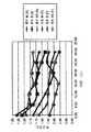
図11は本発明の試験された電極の正規化された応答のプロットである。4つのセンサ(XXS,XS,X,M)が図11および表2内で比較される。 FIG. 11 is a plot of the normalized response of the tested electrode of the present invention. Four sensors (XXX, XS, X, M) are compared in FIG.
図11および表2に見られるように、S電極が水分の存在の全体に対し最も反応が良いようである。MとSの電極は両方ともピークを示している。このことは、M電極からのロールオフ(減衰)はS電極に対するピークの約5分後に起こっているので、水分の深さ依存性は皮膚内で吸収されることを示唆している。 As seen in FIG. 11 and Table 2, the S electrode appears to be most responsive to the overall presence of moisture. Both the M and S electrodes show peaks. This suggests that the moisture depth dependence is absorbed in the skin because the roll-off (decay) from the M electrode occurs about 5 minutes after the peak for the S electrode.
SEMスキャナ10は内部アーム上でも試験された。抵抗圧力センサ(例えば図7のセンサ11)がアームに対するセンサ上に印加される圧力を測定するために用いられる。このように、一定の圧力が測定全体に亘って加えられる。最初に乾燥した内部アームがXS,S,M電極を用いて測定される。それから同じ領域はテープでマスクされ、水分薬品が30分間付加される。続く測定は表面をクリーニングした後同じ薬品上で行われる。 The
図12は市販の加湿液を塗布する前に3つの異なるサイズ(M,S,XS)の同心センサ電極についての乾燥した足の裏のアームの測定された等価容量のグラフである。 FIG. 12 is a graph of the measured equivalent capacity of a dry sole arm for three different sized (M, S, XS) concentric sensor electrodes before applying a commercial humidifier.
図13は3つの異なる同心センサ電極について(液塗布後30分)乾燥した皮膚に関し容量の時間依存性の微小変化のプロットである。 FIG. 13 is a plot of the time-dependent minute change in volume for dry skin for three different concentric sensor electrodes (30 minutes after liquid application).
図14は2つの対象物上の3つの異なる同心センサ電極について(液塗布後15分)乾燥した皮膚に関し容量の時間依存性の割合部分変化のプロットである。この実験はより速いサンプリング間隔で、および2つの試験対象の前腕上のみで15分間の液塗布を伴って行われた。再び抵抗圧力センサがアームに対してセンサ上に加えられた圧力を測定するために用いられた。このように、一定の圧力が測定全体に亘って加えられる。最初に乾燥した内部アームがXS,S,M電極を用いて測定される。それから同じ領域はテープでマスクされ、水分薬品が15分間付加される。続く測定は同じ位置で5分ごとに行われる。圧力は50Kオームに維持され、前腕は再び試験された。表面をクリーニングした後同じ薬品上で行われる。ケースAとの比較、および以前の測定との比較において、ケースFに興味深い観察結果に注目した。ケースFは測定開始前にシャワーを浴び、その結果皮膚は水分が比較的飽和した状態にあった。その結果、ケースFについては、適用された深い水分に対するより少ない程度の感度を観察したのである。 FIG. 14 is a plot of the time-dependent fractional change in volume for dry skin for three different concentric sensor electrodes on two objects (15 minutes after liquid application). This experiment was performed at a faster sampling interval and with 15 minutes of liquid application only on the two test subject's forearms. Again, a resistive pressure sensor was used to measure the pressure applied on the sensor against the arm. In this way, a constant pressure is applied throughout the measurement. The first dry inner arm is measured using XS, S, M electrodes. The same area is then masked with tape and moisture chemicals are added for 15 minutes. Subsequent measurements are taken every 5 minutes at the same location. The pressure was maintained at 50K ohms and the forearm was tested again. It is done on the same chemical after cleaning the surface. In comparison with Case A and in comparison with previous measurements, we focused on observations that were interesting for Case F. Case F was showered before the start of the measurement, so that the skin was relatively saturated with moisture. As a result, for Case F, a lesser degree of sensitivity to the applied deep moisture was observed.
実験は、対象が試験前に朝にシャワーを浴びていないことを知った上で、再度ケースFについて時間分解能3分により行われた。液が前膊内側に15分間塗布された。50kΩで圧力が維持された。結果は残存皮膚水分に対する測定の感度を確認した。 The experiment was performed again for Case F with a time resolution of 3 minutes, knowing that the subject was not taking a shower in the morning before the test. The liquid was applied for 15 minutes to the inside of the forehead. The pressure was maintained at 50 kΩ. The results confirmed the sensitivity of the measurement to residual skin moisture.
図15はM、SおよびXS電極に対する変化割合対時間についての結果のプロットである。 FIG. 15 is a plot of the results for change rate versus time for the M, S, and XS electrodes.
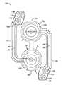
図16は、第1の電極パッド102と第2の電極バッド104を有する層構成のSEMスキャナ電極システム100の好ましい実施例を示す。パッド104は曲線状の経路112に沿った配線34を介してリードライン入力116に接続されている。パッド102は曲線状の経路106に沿った配線34を介してリードライン入力110に接続されている。補剛部材層(例えば図5の層126)がリード入力110および116(痕跡108および114をそれぞれ参照されたい)の直下およびパッド102および104(痕跡122および120をそれぞれ参照されたい)の下に設けられる。 FIG. 16 illustrates a preferred embodiment of a layered SEM
この実施例においては、電極の大きさは、ほぼ幅2300ミル、高さ3900ミルであった。 In this example, the size of the electrode was approximately 2300 mils wide and 3900 mils high.
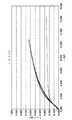
図17はSEMスキャナの機械的なコンプライアンス(力と変位の関係)を人体の突出をプローブできるように展開された、システム100の電極について図示する。ダイアモンド型の記号は上部電極104の応答を、矩形の記号は下部電極102の応答を示す。 FIG. 17 illustrates the mechanical compliance of the SEM scanner (force versus displacement) for the electrodes of the
SEMスキャナ装置10は他の装置、例えば傷の写真を撮るのに用いることができ、あるいはログイン機構や質問機のようにバーコードをスキャンするスキャンシステムに発展することができるカメラ(図示せず)を含んでいても良い。 The
SEMスキャナ装置10を用いている患者は患者のIDに関係するデータを含む腕輪(図示せず)を身につけるようにしても良い。このIDは正しい患者とIDの関係を確認するため、SEMスキャナ10に埋め込まれたカメラによりスキャンされることができる。
代替として腕輪(カメラに加えて)に問い合わせるため、個別のRFスキャナ(図示せず)が用いられても良い。A patient using the
Alternatively, a separate RF scanner (not shown) may be used to query the bracelet (in addition to the camera).
SEMスキャナ装置10は人体の望ましい位置に装置を正しく位置決めすることを奨励するように人間工学的な形をなしていることが好ましい。 The
本発明のSEMスキャナ装置10は、物理的な絶対測定値を発生し、複数の深さで測定を生成できるものである。 The
前述した記載より、本発明は以下を含むが、限定されない種々の態様で実施できることが理解される。 From the foregoing description, it will be appreciated that the present invention may be implemented in various ways, including but not limited to the following.
1.可撓性基板上に埋め込まれたバイポーラRFセンサと、隣接し、前記基板の下に配置された等角圧力パッドと、前記センサに結合されたインターフェース電子回路とを備え、前記等角圧力パッドは前記可撓性基板を支持し、前記可撓性基板が前記患者の皮膚の表面の非平面検知を可能とするようにし、前記インターフェース電子回路は、前記患者の皮膚に応答させるようにRFエネルギーを照射および受信するように構成されたことを特徴とする、患者の外部位置で皮膚下水分を検出する装置。 1. A bipolar RF sensor embedded on a flexible substrate; an adjacent conformal pressure pad disposed under the substrate; and interface electronics coupled to the sensor, the conformal pressure pad comprising: Supporting the flexible substrate, allowing the flexible substrate to provide non-planar sensing of the surface of the patient's skin, and the interface electronics to provide RF energy to respond to the patient's skin. An apparatus for detecting sub-dermal moisture at an external location of a patient, wherein the device is configured to irradiate and receive.
2.前記等角圧力バッドに隣接かつ下の環状スペーサをさらに備え、前記環状スペーサは中央の開口を有し、その開口は前記等角圧力パッドがそこに自由に入って検出することを許容するように構成されたことを特徴とする、実施例1に記載の装置。 2. Further comprising an annular spacer adjacent to and below the conformal pressure pad, the annular spacer having a central opening that allows the conformal pressure pad to freely enter and detect it. Apparatus according to embodiment 1, characterized in that it is configured.
3.前記可撓性基板に亘って離隔配置されたバイポーラRFセンサアレイをさらに備え、前記センサの各々は前記患者の皮膚に個別に応答させるように前記インターフェース電子回路に独立に結合されたことを特徴とする、実施例1に記載の装置。
4.前記センサは皮膚のある目標領域の等価皮膚下容量を測定するように構成され、前記皮膚下容量は皮膚の目標領域の水分含有量に対応することを特徴とする、実施例3に記載の装置。3. Further comprising a bipolar RF sensor array spaced across the flexible substrate, each of the sensors being independently coupled to the interface electronics for individually responding to the patient's skin. The apparatus described in Example 1.
4). The apparatus of embodiment 3, wherein the sensor is configured to measure an equivalent sub-skin volume of a target area of skin, the sub-skin volume corresponding to a moisture content of the target area of skin. .
5.前記センサのアレイは第1のコンタクト面積を有する第1のセンサと前記第1のセンサよりも大きな第2のコンタクト面積を有する第2のセンサを有し、 前記第1および第2のセンサは前記皮膚の異なる深さで応答させることを特徴とする、請求項4に記載の装置。
6.前記基板は、基板層を有する基板組立を備え、前記センサは前記基板の第1の面に埋め込まれた第1の電極と前記基板の第2の面に埋め込まれた第2の電極を有することを特徴とする、実施例4に記載の装置。5. The array of sensors includes a first sensor having a first contact area and a second sensor having a second contact area larger than the first sensor, the first and second sensors being Device according to claim 4, characterized in that it responds at different depths of the skin.
6). The substrate comprises a substrate assembly having a substrate layer, and the sensor has a first electrode embedded in a first surface of the substrate and a second electrode embedded in a second surface of the substrate. The device according to Example 4, characterized in that
7.前記基板層の前記第1の面上に配置された生体親和性のカバー層をさらに備えたことを特徴とする、実施例6に記載の装置。 7). The apparatus of embodiment 6, further comprising a biocompatible cover layer disposed on the first surface of the substrate layer.
8.前記基板層の前記第2の面の下に配置されたカバー層をさらに備えたことを特徴とする、実施例6に記載の装置。 8). The apparatus of embodiment 6, further comprising a cover layer disposed below the second surface of the substrate layer.
9. 前記基板層の前記第の面の下に位置する補剛部材層をさらに備え、
前記補剛部材層は前記センサアレイの専有面積とほぼ同様な専有面積を有することを特徴とする実施例6に記載の装置。9. Further comprising a stiffening member layer located below the first surface of the substrate layer;
The apparatus of embodiment 6, wherein the stiffening member layer has a dedicated area substantially similar to the dedicated area of the sensor array.
10.前記第1の電極は内半径と外半径を有する環状リングを備え、前記第2の電極は前記第1の電極の内半径よりも小さな外半径を備え、前記第2の電極は前記第1の半径と共心であることを特徴とする実施例6に記載の装置。 10. The first electrode includes an annular ring having an inner radius and an outer radius, the second electrode includes an outer radius that is smaller than the inner radius of the first electrode, and the second electrode includes the first electrode. Apparatus according to embodiment 6, characterized in that it is concentric with the radius.
11.前記インターフェース電子回路は前記センサから受け取ったデータを送信するように構成されたことを特徴とする、実施例1に記載の装置。 11. The apparatus of embodiment 1, wherein the interface electronics is configured to transmit data received from the sensor.
12.前記RFセンサと一列に並んで位置する圧力センサをさらに備え、前記圧力センサは前記患者の皮膚のある位置で基板に加えられた圧力を測定するように構成されたことを特徴とする、実施例4に記載の装置。 12 An embodiment further comprising a pressure sensor positioned in line with the RF sensor, wherein the pressure sensor is configured to measure pressure applied to the substrate at a location on the patient's skin. 4. The apparatus according to 4.
13.前記可撓性基板はカプトンあるいはポリイミドから成ることを特徴とする実施例1に記載の装置。 13. The apparatus according to the first embodiment, wherein the flexible substrate is made of Kapton or polyimide.
14.可撓性基板上に埋め込まれたバイポーラRFセンサのアレイと、隣接し、前記基板の下に配置された等角圧力パッドと、を備え、前記等角圧力パッドは前記可撓性基板を支持し、前記可撓性基板が前記患者の皮膚の表面の非平面検知を可能とするようにし、前記センサの各々は前記患者の皮膚に応答させるように独立かつ個別に配線されたことを特徴とする、患者の外部位置で皮膚下水分を検出するスキャナ。 14 An array of bipolar RF sensors embedded on a flexible substrate, and an adjacent conformal pressure pad disposed under the substrate, the conformal pressure pad supporting the flexible substrate. The flexible substrate allows non-planar detection of the surface of the patient's skin, and each of the sensors is independently and individually wired to respond to the patient's skin. A scanner that detects moisture under the skin at the patient's external location.
15.前記センサに結合されたインターフェース電子回路をさらに備え、前記インターフェース電子回路は、RFエネルギーを照射および受信を制御するように構成されたことを特徴とする実施例14に記載のスキャナ。 15. The scanner of
16.前記等角圧力バッドに隣接かつ下の環状スペーサをさらに備え、前記環状スペーサは中央の開口を有し、その開口は前記等角圧力パッドがそこに自由に入って検出することを許容するように構成されたことを特徴とする、実施例14に記載のセンサ。 16. Further comprising an annular spacer adjacent to and below the conformal pressure pad, the annular spacer having a central opening that allows the conformal pressure pad to freely enter and detect it. The sensor according to
17.前記各センサは皮膚のある目標領域の等価皮膚下容量を測定するように構成され、前記皮膚下容量は皮膚の目標領域の水分含有量に対応することを特徴とする、実施例14に記載のスキャナ。 17. Each sensor is configured to measure an equivalent sub-skin volume of a target area of skin, wherein the sub-skin volume corresponds to a moisture content of the target area of the skin, according to Example 14. Scanner.
18.前記センサのアレイは第1のコンタクト面積を有する第1のセンサと前記第1のセンサよりも大きな第2のコンタクト面積を有する第2のセンサを有し、 前記第1および第2のセンサは前記皮膚の異なる深さで応答させることを特徴とする、実施例4に記載のスキャナ。 18. The array of sensors includes a first sensor having a first contact area and a second sensor having a second contact area larger than the first sensor, the first and second sensors being The scanner according to Example 4, characterized in that it responds at different depths of the skin.
19.各センサは、内半径と外半径を有する環状リングの形状の第1の電極と、前記第1の電極の内半径よりも小さな外半径を備えた第2の電極とを備え、前記第2の電極は前記第1の半径と共心であることを特徴とする、実施例14に記載のスキャナ。 19. Each sensor comprises a first electrode in the form of an annular ring having an inner radius and an outer radius, and a second electrode having an outer radius smaller than the inner radius of the first electrode, the second electrode The scanner of
20.前記基板は、基板層を有する基板組立を備え、前記第1の電極は前記基板の第1の面に埋め込まれ、前記第2の電極は前記基板の第2の面に埋め込まれたことを特徴とする、実施例14に記載のスキャナ。 20. The substrate includes a substrate assembly having a substrate layer, wherein the first electrode is embedded in a first surface of the substrate and the second electrode is embedded in a second surface of the substrate. The scanner according to Example 14.
21.前記基板層の前記第1の面上に配置された上側生体親和性カバー層および前記基板層の前記第2の面の下に配置された下側カバー層をさらに備えたことを特徴とする、実施例20に記載のスキャナ。 21. Further comprising an upper biocompatible cover layer disposed on the first surface of the substrate layer and a lower cover layer disposed below the second surface of the substrate layer, A scanner as described in Example 20.
22.前記基板層の前記第2の面の下に位置する補剛部材層をさらに備え、前記補剛部材層は前記センサアレイの専有面積とほぼ同様な専有面積を有することを特徴とする実施例20に記載のスキャナ。 22. Example 20 further comprising a stiffening member layer positioned below the second surface of the substrate layer, the stiffening member layer having a dedicated area substantially similar to the dedicated area of the sensor array. The scanner described in.
23.前記RFセンサと一列に並んで位置する圧力センサをさらに備え、前記圧力センサは前記患者の皮膚の対応する位置で基板に加えられた圧力を測定するように構成されたことを特徴とする、実施例14に記載のスキャナ。 23. Further comprising a pressure sensor positioned in line with the RF sensor, wherein the pressure sensor is configured to measure a pressure applied to the substrate at a corresponding position on the patient's skin, A scanner as described in Example 14.
24.患者の皮膚の目標位置に隣接させて、1つ以上のバイポーラRFセンサを有する可撓性基板を位置決めし、前記可撓性基板を前記目標位置で前記患者の皮膚に適合させ、RFエネルギーを発生させ、患者の皮膚に対し放射し、前記目標位置でその位置における皮膚下水分(SEM)の指標として皮膚の容量を測定する、患者の皮膚の目標位置での圧力潰瘍の形成をモニタする方法。 24. Positioning a flexible substrate having one or more bipolar RF sensors adjacent to a target location on the patient's skin, adapting the flexible substrate to the patient's skin at the target location, and generating RF energy Irradiating the patient's skin and measuring the volume of the skin as an indicator of sub-skin moisture (SEM) at the target location at the target location, and monitoring the formation of pressure ulcers at the target location of the patient's skin.
25.前記1つ以上のセンサは前記基板に亘って配置されたセンサのアレイであり、前記1つ以上のセンサはこれらを独立に励起するために個別に制御されることを特徴とする、実施例24に記載の方法。 25.
26.患者の皮膚上の目標位置で基板に与えられた圧力を測定することをさらに備えた、実施例24に記載の方法。 26. 25. The method of example 24, further comprising measuring the pressure applied to the substrate at a target location on the patient's skin.
27.アレイをなすセンサのそれぞれで前記基板に与えられた圧力が測定されることをさらに備えた、実施例25に記載の方法。 27. 26. The method of example 25, further comprising measuring the pressure applied to the substrate at each of the sensors in the array.
上記記述は多くの詳細が含まれているが、これらは本発明の範囲を限定するものとしては解釈されるべきではなく、単に本発明の現在好ましい実施例のいくつかを説明を提供するにすぎない。したがって、本発明の範囲は当業者にとって容易に想到される他の実施例を含み、本発明の範囲は添付の請求項以外によって制限されることはないことが理解され、すなわち、単数で表現された要素は、特に述べられない限り、「1つおよびただ1つ」を意味することはなく、むしろ「1つまたはそれ以上」を意味する。当業者に知られた上述した実施例の要素に対するすべての構造的、化学的、機能的な等価物はここに参考として組み入れられ、請求項により含まれることが意図される。さらに、装置あるいは方法については、本発明により解決されるべき問題を、本発明の請求項に含まれることは、それぞれおよびその都度述べる必要はない。さらに、本開示における要素、部品、方法のステップは、それらが請求項中に明確に引用されているかにかかわらず、公衆に供したものではない。means forを用いて明確に表現されない限り、請求項の要素が米国特許法35USC112、第6段落のもとで解釈されることはない。
Claims (27)
Translated fromJapanese隣接し、前記基板の下に配置された等角圧力パッドと、
前記センサに結合されたインターフェース電子回路とを備え、
前記等角圧力パッドは前記可撓性基板を支持し、前記可撓性基板が前記患者の皮膚の表面の非平面検知を可能とするようにし、
前記インターフェース電子回路は、前記患者の皮膚に応答させるようにRFエネルギーを照射および受信するように構成されたことを特徴とする、患者の外部位置で皮膚下水分を検出する装置A bipolar RF sensor embedded on a flexible substrate;
An isometric pressure pad adjacent and disposed below the substrate;
Interface electronics coupled to the sensor,
The conformal pressure pad supports the flexible substrate, the flexible substrate enabling non-planar detection of the surface of the patient's skin;
Apparatus for detecting sub-skin moisture at an external location of a patient, wherein the interface electronics is configured to irradiate and receive RF energy to respond to the patient's skin
前記環状スペーサは中央の開口を有し、その開口は前記等角圧力パッドがそこに自由に入って検出することを許容するように構成されたことを特徴とする、請求項1に記載の装置。Further comprising an annular spacer adjacent and below the conformal pressure pad;
The apparatus of claim 1, wherein the annular spacer has a central opening that is configured to allow the conformal pressure pad to freely enter and detect it. .
前記センサの各々は前記患者の皮膚に個別に応答させるように前記インターフェース電子回路に独立に結合されたことを特徴とする、請求項1に記載の装置。A bipolar RF sensor array spaced apart across the flexible substrate;
The apparatus of claim 1, wherein each of the sensors is independently coupled to the interface electronics for individually responding to the patient's skin.
前記皮膚下容量は皮膚の目標領域の水分含有量に対応することを特徴とする、請求項3に記載の装置。The sensor is configured to measure an equivalent subdermal volume of a target area of the skin;
4. A device according to claim 3, characterized in that the sub-skin volume corresponds to the moisture content of the target area of the skin.
前記第1および第2のセンサは前記皮膚の異なる深さで応答させることを特徴とする、請求項4に記載の装置。The array of sensors includes a first sensor having a first contact area and a second sensor having a second contact area larger than the first sensor;
The apparatus of claim 4, wherein the first and second sensors are responsive at different depths of the skin.
前記センサは前記基板の第1の面に埋め込まれた第1の電極と前記基板の第2の面に埋め込まれた第2の電極を有することを特徴とする、請求項4に記載の装置。The substrate comprises a substrate assembly having a substrate layer;
The apparatus of claim 4, wherein the sensor has a first electrode embedded in a first surface of the substrate and a second electrode embedded in a second surface of the substrate.
前記補剛部材層は前記センサアレイの専有面積とほぼ同様な専有面積を有することを特徴とする請求項6に記載の装置。Further comprising a stiffening member layer located below the first surface of the substrate layer;
7. The apparatus of claim 6, wherein the stiffening member layer has a dedicated area that is substantially similar to a dedicated area of the sensor array.
前記第2の電極は前記第1の電極の内半径よりも小さな外半径を備え、
前記第2の電極は前記第1の半径と共心であることを特徴とする請求項6に記載の装置。The first electrode comprises an annular ring having an inner radius and an outer radius;
The second electrode has an outer radius smaller than an inner radius of the first electrode;
The apparatus of claim 6, wherein the second electrode is concentric with the first radius.
前記圧力センサは前記患者の皮膚のある位置で基板に加えられた圧力を測定するように構成されたことを特徴とする、請求項4に記載の装置。A pressure sensor positioned in a line with the RF sensor;
The apparatus of claim 4, wherein the pressure sensor is configured to measure pressure applied to a substrate at a location on the patient's skin.
隣接し、前記基板の下に配置された等角圧力パッドと、を備え、
前記等角圧力パッドは前記可撓性基板を支持し、前記可撓性基板が前記患者の皮膚の表面の非平面検知を可能とするようにし、
前記センサの各々は前記患者の皮膚に応答させるように独立かつ個別に配線されたことを特徴とする、患者の外部位置で皮膚下水分を検出するスキャナ。An array of bipolar RF sensors embedded on a flexible substrate;
An isometric pressure pad disposed adjacent and below the substrate,
The conformal pressure pad supports the flexible substrate, the flexible substrate enabling non-planar detection of the surface of the patient's skin;
A scanner for detecting sub-skin moisture at an external location of a patient, wherein each of the sensors is independently and individually wired to respond to the patient's skin.
前記インターフェース電子回路は、RFエネルギーを照射および受信を制御するように構成されたことを特徴とする請求項14に記載のスキャナ。Further comprising interface electronics coupled to the sensor;
The scanner of claim 14, wherein the interface electronics is configured to control the irradiation and reception of RF energy.
前記環状スペーサは中央の開口を有し、その開口は前記等角圧力パッドがそこに自由に入って検出することを許容するように構成されたことを特徴とする、請求項14に記載のセンサ。Further comprising an annular spacer adjacent and below the conformal pressure pad;
15. A sensor according to claim 14, wherein the annular spacer has a central opening, the opening being configured to allow the conformal pressure pad to freely enter and detect it. .
前記皮膚下容量は皮膚の目標領域の水分含有量に対応することを特徴とする、請求項14に記載のスキャナ。Each of the sensors is configured to measure an equivalent subdermal volume of a target area of the skin;
The scanner according to claim 14, wherein the sub-skin volume corresponds to a moisture content of a target area of the skin.
前記第1および第2のセンサは前記皮膚の異なる深さで応答させることを特徴とする、請求項4に記載のスキャナ。The array of sensors includes a first sensor having a first contact area and a second sensor having a second contact area larger than the first sensor;
The scanner according to claim 4, wherein the first and second sensors respond at different depths of the skin.
前記第2の電極は前記第1の半径と共心であることを特徴とする、請求項14に記載のスキャナ。Each sensor comprises a first electrode in the form of an annular ring having an inner radius and an outer radius, and a second electrode having an outer radius smaller than the inner radius of the first electrode,
The scanner according to claim 14, wherein the second electrode is concentric with the first radius.
前記第1の電極は前記基板の第1の面に埋め込まれ、前記第2の電極は前記基板の第2の面に埋め込まれたことを特徴とする、請求項14に記載のスキャナ。The substrate comprises a substrate assembly having a substrate layer;
The scanner according to claim 14, wherein the first electrode is embedded in a first surface of the substrate, and the second electrode is embedded in a second surface of the substrate.
前記補剛部材層は前記センサアレイの専有面積とほぼ同様な専有面積を有することを特徴とする請求項20に記載のスキャナ。Further comprising a stiffening member layer located below the second surface of the substrate layer;
21. The scanner according to claim 20, wherein the stiffening member layer has a dedicated area substantially similar to a dedicated area of the sensor array.
前記圧力センサは前記患者の皮膚の対応する位置で基板に加えられた圧力を測定するように構成されたことを特徴とする、請求項14に記載のスキャナ。A pressure sensor positioned in a line with the RF sensor;
The scanner of claim 14, wherein the pressure sensor is configured to measure pressure applied to a substrate at a corresponding location on the patient's skin.
前記可撓性基板を前記目標位置で前記患者の皮膚に適合させ、
RFエネルギーを発生させ、患者の皮膚に対し放射し、
前記目標位置でその位置における皮膚下水分(SEM)の指標として皮膚の容量を測定する、患者の皮膚の目標位置での圧力潰瘍の形成をモニタする方法。Positioning a flexible substrate having one or more bipolar RF sensors adjacent to a target location on a patient's skin;
Adapting the flexible substrate to the patient's skin at the target location;
Generate RF energy, radiate it to the patient's skin,
A method of monitoring the formation of a pressure ulcer at a target location on a patient's skin, measuring the volume of the skin at the target location as an index of subdermal moisture (SEM) at that location.
前記1つ以上のセンサはこれらを独立に励起するために個別に制御されることを特徴とする、請求項24に記載の方法。The one or more sensors are an array of sensors disposed across the substrate;
The method of claim 24, wherein the one or more sensors are individually controlled to excite them independently.
Applications Claiming Priority (4)
| Application Number | Priority Date | Filing Date | Title |
|---|---|---|---|
| US33275510P | 2010-05-08 | 2010-05-08 | |
| US61/332,755 | 2010-05-08 | ||
| US201161453852P | 2011-03-17 | 2011-03-17 | |
| US61/453,852 | 2011-03-17 |
Related Parent Applications (1)
| Application Number | Title | Priority Date | Filing Date |
|---|---|---|---|
| JP2015117500ADivisionJP5978352B2 (en) | 2010-05-08 | 2015-06-10 | SEM scanner detection apparatus, system and method for early detection of ulcers |
Related Child Applications (1)
| Application Number | Title | Priority Date | Filing Date |
|---|---|---|---|
| JP2018145355ADivisionJP6574030B2 (en) | 2010-05-08 | 2018-08-01 | SEM scanner detection apparatus, system and method for early detection of ulcers |
Publications (1)
| Publication Number | Publication Date |
|---|---|
| JP2016198547Atrue JP2016198547A (en) | 2016-12-01 |
Family
ID=44914913
Family Applications (4)
| Application Number | Title | Priority Date | Filing Date |
|---|---|---|---|
| JP2013509311AActiveJP5763751B2 (en) | 2010-05-08 | 2011-05-06 | SEM scanner detection apparatus, system and method for early detection of ulcers |
| JP2015117500AActiveJP5978352B2 (en) | 2010-05-08 | 2015-06-10 | SEM scanner detection apparatus, system and method for early detection of ulcers |
| JP2016143702APendingJP2016198547A (en) | 2010-05-08 | 2016-07-21 | Sem scanner sensing apparatus, system and methodology for early detection of ulcers |
| JP2018145355AActiveJP6574030B2 (en) | 2010-05-08 | 2018-08-01 | SEM scanner detection apparatus, system and method for early detection of ulcers |
Family Applications Before (2)
| Application Number | Title | Priority Date | Filing Date |
|---|---|---|---|
| JP2013509311AActiveJP5763751B2 (en) | 2010-05-08 | 2011-05-06 | SEM scanner detection apparatus, system and method for early detection of ulcers |
| JP2015117500AActiveJP5978352B2 (en) | 2010-05-08 | 2015-06-10 | SEM scanner detection apparatus, system and method for early detection of ulcers |
Family Applications After (1)
| Application Number | Title | Priority Date | Filing Date |
|---|---|---|---|
| JP2018145355AActiveJP6574030B2 (en) | 2010-05-08 | 2018-08-01 | SEM scanner detection apparatus, system and method for early detection of ulcers |
Country Status (18)
| Country | Link |
|---|---|
| US (9) | US20130123587A1 (en) |
| EP (6) | EP4335362A1 (en) |
| JP (4) | JP5763751B2 (en) |
| KR (2) | KR101688918B1 (en) |
| CN (1) | CN102933958B (en) |
| AU (1) | AU2011253253B2 (en) |
| BR (3) | BR112012028408B8 (en) |
| CA (3) | CA2811609C (en) |
| DK (3) | DK3581105T3 (en) |
| ES (3) | ES2927727T3 (en) |
| FI (2) | FI3155965T3 (en) |
| HU (1) | HUE059711T2 (en) |
| LT (3) | LT3155965T (en) |
| PL (1) | PL3581105T3 (en) |
| PT (4) | PT2569618T (en) |
| SG (1) | SG185131A1 (en) |
| SI (2) | SI4122383T1 (en) |
| WO (1) | WO2011143071A2 (en) |
Families Citing this family (101)
| Publication number | Priority date | Publication date | Assignee | Title |
|---|---|---|---|---|
| US9123614B2 (en) | 2008-10-07 | 2015-09-01 | Mc10, Inc. | Methods and applications of non-planar imaging arrays |
| US8097926B2 (en) | 2008-10-07 | 2012-01-17 | Mc10, Inc. | Systems, methods, and devices having stretchable integrated circuitry for sensing and delivering therapy |
| US8389862B2 (en) | 2008-10-07 | 2013-03-05 | Mc10, Inc. | Extremely stretchable electronics |
| JP5763751B2 (en) | 2010-05-08 | 2015-08-12 | ザ、リージェンツ、オブ、ザ、ユニバーシティ、オブ、カリフォルニアThe Regents Of The University Of California | SEM scanner detection apparatus, system and method for early detection of ulcers |
| CA2811610A1 (en)* | 2010-05-08 | 2011-11-17 | Majid Sarrafzadeh | Method, system, and apparatus for pressure image registration |
| JP5922457B2 (en)* | 2012-03-26 | 2016-05-24 | テルモ株式会社 | Pressure ulcer detection device and its operating method |
| US9326685B2 (en)* | 2012-09-14 | 2016-05-03 | Conopco, Inc. | Device for evaluating condition of skin or hair |
| WO2014058473A1 (en) | 2012-10-09 | 2014-04-17 | Mc10, Inc. | Conformal electronics integrated with apparel |
| US9171794B2 (en) | 2012-10-09 | 2015-10-27 | Mc10, Inc. | Embedding thin chips in polymer |
| GB201317746D0 (en) | 2013-10-08 | 2013-11-20 | Smith & Nephew | PH indicator |
| CN103271739B (en)* | 2013-05-06 | 2015-04-15 | 清华大学 | Method and device for skin moisture measurement |
| US9706647B2 (en) | 2013-05-14 | 2017-07-11 | Mc10, Inc. | Conformal electronics including nested serpentine interconnects |
| EP3071096A4 (en) | 2013-11-22 | 2017-08-09 | Mc10, Inc. | Conformal sensor systems for sensing and analysis of cardiac activity |
| US10485118B2 (en) | 2014-03-04 | 2019-11-19 | Mc10, Inc. | Multi-part flexible encapsulation housing for electronic devices and methods of making the same |
| WO2015195720A1 (en)* | 2014-06-16 | 2015-12-23 | The Regents Of The University Of California | Methods and apparatus for monitoring wound healing using impedance spectroscopy |
| USD781270S1 (en) | 2014-10-15 | 2017-03-14 | Mc10, Inc. | Electronic device having antenna |
| WO2016081946A1 (en)* | 2014-11-21 | 2016-05-26 | The Regents Of The University Of California | Fast behavior and abnormality detection |
| CN105807981A (en)* | 2014-12-31 | 2016-07-27 | 中兴通讯股份有限公司 | User terminal and working method thereof |
| WO2016134306A1 (en) | 2015-02-20 | 2016-08-25 | Mc10, Inc. | Automated detection and configuration of wearable devices based on on-body status, location, and/or orientation |
| WO2016140961A1 (en)* | 2015-03-02 | 2016-09-09 | Mc10, Inc. | Perspiration sensor |
| US20180360344A1 (en)* | 2017-06-19 | 2018-12-20 | Bruin Biometrics, Llc | Apparatus and methods for determining damaged tissue using sub-epidermal moisture measurements |
| CA2982249C (en) | 2015-04-24 | 2019-12-31 | Bruin Biometrics, Llc | Apparatus and methods for determining damaged tissue using sub-epidermal moisture measurements |
| WO2016172264A1 (en)* | 2015-04-24 | 2016-10-27 | Bruin Biometrics Llc | Apparatus and methods for determining damaged tissue using sub-epidermal moisture measurements |
| CN104939796A (en)* | 2015-05-18 | 2015-09-30 | 中国人民解放军第四军医大学 | Visual pocket used for skin grafting |
| US10542961B2 (en) | 2015-06-15 | 2020-01-28 | The Research Foundation For The State University Of New York | System and method for infrasonic cardiac monitoring |
| US11324948B2 (en) | 2015-07-21 | 2022-05-10 | Koninklijke Philips N.V. | Device for radio-frequency skin treatment |
| US10709384B2 (en) | 2015-08-19 | 2020-07-14 | Mc10, Inc. | Wearable heat flux devices and methods of use |
| EP4079383A3 (en) | 2015-10-01 | 2023-02-22 | Medidata Solutions, Inc. | Method and system for interacting with a virtual environment |
| US10532211B2 (en) | 2015-10-05 | 2020-01-14 | Mc10, Inc. | Method and system for neuromodulation and stimulation |
| US10673280B2 (en) | 2016-02-22 | 2020-06-02 | Mc10, Inc. | System, device, and method for coupled hub and sensor node on-body acquisition of sensor information |
| US10277386B2 (en) | 2016-02-22 | 2019-04-30 | Mc10, Inc. | System, devices, and method for on-body data and power transmission |
| WO2017181194A1 (en)* | 2016-04-15 | 2017-10-19 | Universal Care Solutions, Llc | Systems and methods for classification and treatment of decubitus ulcers |
| CN109310340A (en) | 2016-04-19 | 2019-02-05 | Mc10股份有限公司 | Method and system for measuring sweat |
| CA3023772A1 (en) | 2016-05-13 | 2017-11-16 | Smith & Nephew Plc | Sensor enabled wound monitoring and therapy apparatus |
| WO2017214188A1 (en) | 2016-06-06 | 2017-12-14 | University Of Massachusetts | Systems and methods for prevention of pressure ulcers |
| US10447347B2 (en) | 2016-08-12 | 2019-10-15 | Mc10, Inc. | Wireless charger and high speed data off-loader |
| US20230200728A9 (en)* | 2016-11-11 | 2023-06-29 | 1625986 Ontario Limited | Fat Burning Monitoring |
| ES2966366T3 (en) | 2017-02-03 | 2024-04-22 | Bbi Medical Innovations Llc | Tissue viability measurement |
| KR102694209B1 (en) | 2017-02-03 | 2024-08-13 | 브루인 바이오메트릭스, 엘엘씨 | Measurement of edema |
| GB2569921B (en)* | 2017-02-03 | 2022-06-01 | Bruin Biometrics Llc | Bisymmetric comparison of sub-epidermal moisture values |
| GB2591707B (en)* | 2017-02-03 | 2021-11-17 | Bruin Biometrics Llc | Measurement of susceptibility to diabetic foot ulcers |
| US11690570B2 (en) | 2017-03-09 | 2023-07-04 | Smith & Nephew Plc | Wound dressing, patch member and method of sensing one or more wound parameters |
| EP3592230A1 (en) | 2017-03-09 | 2020-01-15 | Smith & Nephew PLC | Apparatus and method for imaging blood in a target region of tissue |
| JP7091356B2 (en) | 2017-03-09 | 2022-06-27 | スミス アンド ネフュー ピーエルシー | Devices, devices, and methods for determining skin perfusion pressure |
| CA3059516A1 (en)* | 2017-04-11 | 2018-10-18 | Smith & Nephew Plc | Component positioning and stress relief for sensor enabled wound dressings |
| EP3635733A1 (en) | 2017-05-15 | 2020-04-15 | Smith & Nephew plc | Negative pressure wound therapy system using eulerian video magnification |
| AU2018269112B2 (en) | 2017-05-15 | 2024-05-02 | Smith & Nephew Plc | Wound analysis device and method |
| JP7189159B2 (en) | 2017-06-23 | 2022-12-13 | スミス アンド ネフュー ピーエルシー | Sensor placement for sensor-enabled wound monitoring or therapy |
| CN109199323B (en)* | 2017-06-29 | 2021-01-26 | 京东方科技集团股份有限公司 | Skin detection device, product information determination method, device and system |
| GB201804502D0 (en) | 2018-03-21 | 2018-05-02 | Smith & Nephew | Biocompatible encapsulation and component stress relief for sensor enabled negative pressure wound therapy dressings |
| GB201809007D0 (en) | 2018-06-01 | 2018-07-18 | Smith & Nephew | Restriction of sensor-monitored region for sensor-enabled wound dressings |
| SG11202000913XA (en) | 2017-08-10 | 2020-02-27 | Smith & Nephew | Positioning of sensors for sensor enabled wound monitoring or therapy |
| GB201718870D0 (en) | 2017-11-15 | 2017-12-27 | Smith & Nephew Inc | Sensor enabled wound therapy dressings and systems |
| CN111093477B (en) | 2017-09-10 | 2023-09-12 | 史密夫及内修公开有限公司 | Systems and methods for inspecting packages and components in sensor-equipped wound dressings |
| GB201804971D0 (en) | 2018-03-28 | 2018-05-09 | Smith & Nephew | Electrostatic discharge protection for sensors in wound therapy |
| GB201718859D0 (en) | 2017-11-15 | 2017-12-27 | Smith & Nephew | Sensor positioning for sensor enabled wound therapy dressings and systems |
| WO2019063481A1 (en) | 2017-09-27 | 2019-04-04 | Smith & Nephew Plc | Ph sensing for sensor enabled negative pressure wound monitoring and therapy apparatuses |
| WO2019072531A1 (en) | 2017-09-28 | 2019-04-18 | Smith & Nephew Plc | Neurostimulation and monitoring using sensor enabled wound monitoring and therapy apparatus |
| US11559438B2 (en) | 2017-11-15 | 2023-01-24 | Smith & Nephew Plc | Integrated sensor enabled wound monitoring and/or therapy dressings and systems |
| AU2018368707B2 (en)* | 2017-11-16 | 2024-03-07 | Bruin Biometrics, Llc | Strategic treatment of pressure ulcer using sub-epidermal moisture values |
| US20190175098A1 (en)* | 2017-12-07 | 2019-06-13 | Bruin Biometrics, Llc | SEM Trend Analysis |
| AU2019217995B2 (en) | 2018-02-09 | 2024-11-14 | Bruin Biometrics, Llc | Detection of tissue damage |
| EP3755223A1 (en) | 2018-02-21 | 2020-12-30 | T.J.Smith And Nephew, Limited | Monitoring of body loading and body position for the treatment of pressure ulcers or other injuries |
| WO2019234011A1 (en) | 2018-06-04 | 2019-12-12 | T.J.Smith And Nephew,Limited | Device communication management in user activity monitoring systems |
| EP3586724A1 (en)* | 2018-06-27 | 2020-01-01 | Koninklijke Philips N.V. | Device for use in determining a hydration level of skin |
| US11064918B2 (en) | 2018-07-24 | 2021-07-20 | Baxter International Inc. | Patch-based physiological sensor |
| US11202578B2 (en)* | 2018-07-24 | 2021-12-21 | Welch Allyn, Inc. | Patch-based physiological sensor |
| US10842392B2 (en)* | 2018-07-24 | 2020-11-24 | Baxter International Inc. | Patch-based physiological sensor |
| US11096590B2 (en)* | 2018-07-24 | 2021-08-24 | Baxter International Inc. | Patch-based physiological sensor |
| WO2020023681A1 (en)* | 2018-07-24 | 2020-01-30 | Tosense, Inc. | Patch-based physiological sensor |
| US11116410B2 (en) | 2018-07-24 | 2021-09-14 | Baxter International Inc. | Patch-based physiological sensor |
| GB201814011D0 (en) | 2018-08-29 | 2018-10-10 | Smith & Nephew | Componet positioning and encapsulation for sensor enabled wound dressings |
| US10847393B2 (en) | 2018-09-04 | 2020-11-24 | Applied Materials, Inc. | Method and apparatus for measuring process kit centering |
| US10794681B2 (en) | 2018-09-04 | 2020-10-06 | Applied Materials, Inc. | Long range capacitive gap measurement in a wafer form sensor system |
| US11521872B2 (en) | 2018-09-04 | 2022-12-06 | Applied Materials, Inc. | Method and apparatus for measuring erosion and calibrating position for a moving process kit |
| US11404296B2 (en) | 2018-09-04 | 2022-08-02 | Applied Materials, Inc. | Method and apparatus for measuring placement of a substrate on a heater pedestal |
| US11342210B2 (en) | 2018-09-04 | 2022-05-24 | Applied Materials, Inc. | Method and apparatus for measuring wafer movement and placement using vibration data |
| EP3849401A1 (en) | 2018-09-12 | 2021-07-21 | Smith & Nephew plc | Device, apparatus and method of determining skin perfusion pressure |
| WO2020064937A1 (en) | 2018-09-28 | 2020-04-02 | T.J.Smith And Nephew,Limited | Optical fibers for optically sensing through wound dressings |
| PL3861601T3 (en) | 2018-10-11 | 2024-06-10 | Bruin Biometrics, Llc | DEVICE WITH A SINGLE-USE ELEMENT |
| GB2577927B (en)* | 2018-10-11 | 2023-07-26 | Zedsen Ltd | An Apparatus for Producing Output Data Relating to Skin Conditions |
| GB201816838D0 (en) | 2018-10-16 | 2018-11-28 | Smith & Nephew | Systems and method for applying biocompatible encapsulation to sensor enabled wound monitoring and therapy dressings |
| CN109596264A (en)* | 2018-11-14 | 2019-04-09 | 珠海市万瑙特健康科技有限公司 | Array pressure sensor detection device |
| EP3653110B1 (en)* | 2018-11-16 | 2025-09-03 | Hill-Rom Services, Inc. | System for determining a pressure injury score and altering a treatment plan based on the pressure injury score |
| GB201820927D0 (en) | 2018-12-21 | 2019-02-06 | Smith & Nephew | Wound therapy systems and methods with supercapacitors |
| JP7529681B2 (en) | 2019-03-18 | 2024-08-06 | スミス アンド ネフュー ピーエルシー | Design rules for sensor integrated boards |
| EP3962360B1 (en) | 2019-05-01 | 2024-06-05 | T.J.Smith And Nephew, Limited | Communication and user interface control in user activity monitoring systems |
| US20210076974A1 (en)* | 2019-09-17 | 2021-03-18 | Bruin Biometrics, Llc | System for Strategic Monitoring and Treatment of Pressure Ulcer Using Sub-Epidermal Moisture Values |
| GB201914443D0 (en) | 2019-10-07 | 2019-11-20 | Smith & Nephew | Sensor enabled negative pressure wound monitoring apparatus with different impedances inks |
| IL296904A (en)* | 2020-04-03 | 2022-12-01 | Bruin Biometrics Llc | Biocapacitance sensor |
| EP4139904A1 (en) | 2020-04-21 | 2023-03-01 | T.J. Smith and Nephew, Limited | Wound treatment management using augmented reality overlay |
| US12419521B2 (en)* | 2020-08-21 | 2025-09-23 | Empo Health, Inc. | System to detect foot abnormalities |
| EP4210561A4 (en)* | 2020-09-11 | 2024-09-25 | Xsensor Technology Corporation | Intelligent weight system |
| US12310742B2 (en) | 2020-09-11 | 2025-05-27 | Xsensor Technology Corporation | Intelligent weight support system |
| CN112315428B (en)* | 2020-11-03 | 2021-12-28 | 兰州大学 | An Optical Sensing Device for Measuring Human Pressure Injury |
| MX2023009108A (en) | 2021-02-03 | 2023-08-09 | Bruin Biometrics Llc | Methods of treating deep and early-stage pressure induced tissue damage. |
| WO2022226043A2 (en)* | 2021-04-20 | 2022-10-27 | Bruin Biometrics, Llc | Detection of tissue damage from personal protective equipment |
| WO2023183440A1 (en)* | 2022-03-23 | 2023-09-28 | Nikon Corporation | Flexible skin sensors for skin hydration measurements |
| CN115089213B (en)* | 2022-07-04 | 2025-06-24 | 林丹柯 | A special integrated circuit chip for skin collagen detection |
| CN117281478B (en)* | 2023-10-17 | 2024-05-28 | 天津大学 | Skin disease auxiliary diagnosis device and system |
| US20250128426A1 (en)* | 2023-10-24 | 2025-04-24 | City University Of Hong Kong | Transparent and flexible electronic skin and method for fabricating the same |
Citations (7)
| Publication number | Priority date | Publication date | Assignee | Title |
|---|---|---|---|---|
| US4860753A (en)* | 1987-11-04 | 1989-08-29 | The Gillette Company | Monitoring apparatus |
| JP2003169787A (en)* | 2001-12-05 | 2003-06-17 | Matsushita Electric Ind Co Ltd | Skin moisture meter |
| JP2003169788A (en)* | 2001-12-05 | 2003-06-17 | Matsushita Electric Ind Co Ltd | Skin moisture meter |
| JP2005052227A (en)* | 2003-08-07 | 2005-03-03 | Naoyuki Minorikawa | Instrument measuring water content of stratum corneum non-affected by electrolyte component on skin surface |
| US20050177061A1 (en)* | 2001-03-23 | 2005-08-11 | Delfin Technologies, Ltd. | Method for measuring of edema |
| JP2005312927A (en)* | 2004-04-01 | 2005-11-10 | Nippon System Kenkyusho:Kk | Surface property simultaneous measuring probe, and surface property simultaneous measuring method and device using same |
| US20090009193A1 (en)* | 2007-07-06 | 2009-01-08 | Chung Yuan Christian University | Moisture-Sensitive Element with an Interdigital Capacitor and Fabrication thereof |
Family Cites Families (266)
| Publication number | Priority date | Publication date | Assignee | Title |
|---|---|---|---|---|
| US3851641A (en) | 1973-11-29 | 1974-12-03 | J Toole | Method and apparatus for determining internal impedance of animal body part |
| US4295009A (en) | 1980-03-07 | 1981-10-13 | Amp Incorporated | Piezoelectric audio transducer mounting and electrical connector |
| US4557271A (en) | 1983-05-11 | 1985-12-10 | Stoller Kenneth P | Method and apparatus for detecting body illness, dysfunction, disease and/or pathology |
| JPS6063039A (en)* | 1983-09-19 | 1985-04-11 | 株式会社肌粧品科学開放研究所 | Skin moisture measuring apparatus |
| US4857716A (en) | 1986-05-12 | 1989-08-15 | Clinicom Incorporated | Patient identification and verification system and method |
| JPH0524131Y2 (en) | 1986-11-07 | 1993-06-18 | ||
| FR2629204B1 (en)* | 1988-03-25 | 1990-12-14 | Oreal | DEVICE FOR PERFORMING A MEASUREMENT OF THE WATER CONTENT OF A SUBSTRATE, IN PARTICULAR OF THE SKIN |
| US5152296A (en)* | 1990-03-01 | 1992-10-06 | Hewlett-Packard Company | Dual-finger vital signs monitor |
| US5158091A (en)* | 1990-11-30 | 1992-10-27 | Ivac Corporation | Tonometry system for determining blood pressure |
| US5226245A (en) | 1991-09-20 | 1993-07-13 | Lamont William D | Protective boot structure |
| DE69232191T2 (en) | 1991-12-17 | 2002-08-29 | Kinetic Concepts, Inc. | PNEUMATIC COMPRESSION DEVICE FOR USE IN THE MEDICAL AREA |
| US5292341A (en) | 1992-03-02 | 1994-03-08 | Siemens Pacesetter, Inc. | Method and system for determining and automatically adjusting the sensor parameters of a rate-responsive pacemaker |
| US5664231A (en) | 1994-04-29 | 1997-09-02 | Tps Electronics | PCMCIA interface card for coupling input devices such as barcode scanning engines to personal digital assistants and palmtop computers |
| NO180024C (en) | 1994-10-11 | 1997-01-29 | Oerjan G Martinsen | Measurement of moisture in the skin |
| US6671563B1 (en) | 1995-05-15 | 2003-12-30 | Alaris Medical Systems, Inc. | System and method for collecting data and managing patient care |
| US20010051783A1 (en)* | 1996-02-23 | 2001-12-13 | Stuart D. Edwards | Method and apparatus for treatment of air way obstructions |
| US5815416A (en) | 1996-04-19 | 1998-09-29 | Vlsi Technology, Inc. | Method of measuring energy consumption in a circuit simulator |
| US6135781A (en) | 1996-07-17 | 2000-10-24 | Minnesota Mining And Manufacturing Company | Electrical interconnection system and device |
| US6778090B2 (en)* | 1996-09-04 | 2004-08-17 | Paul Newham | Modular system for monitoring the presence of a person using a variety of sensing devices |
| US7657297B2 (en)* | 2004-05-03 | 2010-02-02 | Dexcom, Inc. | Implantable analyte sensor |
| US20050096513A1 (en)* | 1997-11-11 | 2005-05-05 | Irvine Sensors Corporation | Wearable biomonitor with flexible thinned integrated circuit |
| US6175752B1 (en)* | 1998-04-30 | 2001-01-16 | Therasense, Inc. | Analyte monitoring device and methods of use |
| US6949816B2 (en)* | 2003-04-21 | 2005-09-27 | Motorola, Inc. | Semiconductor component having first surface area for electrically coupling to a semiconductor chip and second surface area for electrically coupling to a substrate, and method of manufacturing same |
| US6223088B1 (en) | 1998-11-09 | 2001-04-24 | Katecho, Incorporated | Electrode and connector assembly and method for using same |
| US6330479B1 (en)* | 1998-12-07 | 2001-12-11 | The Regents Of The University Of California | Microwave garment for heating and/or monitoring tissue |
| ATE343963T1 (en) | 1999-04-20 | 2006-11-15 | Nova Technology Corp | METHOD AND DEVICE FOR MEASURING THE WATER CONTENT IN A SUBSTRATE |
| JP2001110488A (en) | 1999-08-04 | 2001-04-20 | Japan Aviation Electronics Industry Ltd | Connector structure for connection between boards |
| JP3722654B2 (en) | 1999-09-03 | 2005-11-30 | 株式会社タニタ | Physical condition recovery judgment device after childbirth |
| US6368284B1 (en) | 1999-11-16 | 2002-04-09 | Cardiac Intelligence Corporation | Automated collection and analysis patient care system and method for diagnosing and monitoring myocardial ischemia and outcomes thereof |
| JP2001178705A (en) | 1999-12-22 | 2001-07-03 | Sousei Denshi:Kk | Contact measuring instrument |
| AU2001229916A1 (en) | 2000-01-27 | 2001-08-07 | National Research Council Of Canada | Visible-near infrared spectroscopy in burn injury assessment |
| US20020016535A1 (en) | 2000-01-28 | 2002-02-07 | Martin W. Blake | Subcutaneous glucose measurement device |
| DE60142988D1 (en)* | 2000-03-29 | 2010-10-14 | Eric Flam | DEVICE FOR PREVENTING AND / OR CURING PRESENCE |
| US6738798B1 (en) | 2000-06-01 | 2004-05-18 | Ge Medical Technology Services, Inc. | Automated monitoring of collection of operational data from medical imaging devices |
| US7030764B2 (en) | 2000-06-09 | 2006-04-18 | Bed-Check Corporation | Apparatus and method for reducing the risk of decubitus ulcers |
| US6646556B1 (en)* | 2000-06-09 | 2003-11-11 | Bed-Check Corporation | Apparatus and method for reducing the risk of decubitus ulcers |
| DE60114318T2 (en)* | 2000-07-03 | 2006-07-13 | Matsushita Electric Works, Ltd., Kadoma | Capacitive moisture sensor and method for its manufacture |
| JP3866943B2 (en) | 2000-08-04 | 2007-01-10 | 株式会社タニタ | Weight management device |
| US6606510B2 (en) | 2000-08-31 | 2003-08-12 | Mallinckrodt Inc. | Oximeter sensor with digital memory encoding patient data |
| CN1247149C (en) | 2000-12-14 | 2006-03-29 | 株式会社阿托哈本9 | Body Impedance Measuring Device |
| US7315767B2 (en)* | 2001-03-06 | 2008-01-01 | Solianis Holding Ag | Impedance spectroscopy based systems and methods |
| AU2002255953A1 (en) | 2001-03-27 | 2002-10-08 | Aron Z. Kain | Wireless system for measuring distension in flexible tubes |
| US6577700B1 (en) | 2001-06-22 | 2003-06-10 | Liang-Shih Fan | Neural network based multi-criteria optimization image reconstruction technique for imaging two- and three-phase flow systems using electrical capacitance tomography |
| CA2455402C (en)* | 2001-07-26 | 2011-10-11 | Medrad, Inc. | Electromagnetic sensors for biological tissue applications and methods for their use |
| WO2003009753A2 (en)* | 2001-07-26 | 2003-02-06 | Chad Bouton | Detection of fluids in tissue |
| US20030116447A1 (en)* | 2001-11-16 | 2003-06-26 | Surridge Nigel A. | Electrodes, methods, apparatuses comprising micro-electrode arrays |
| US20030110662A1 (en) | 2001-12-13 | 2003-06-19 | Gilman Thomas H. | Adherent orthotic pad |
| US7016737B2 (en) | 2002-03-06 | 2006-03-21 | Loma Linda University | Method and device for wound healing |
| JP4071979B2 (en) | 2002-03-29 | 2008-04-02 | 株式会社フィジオン | Standing body composition measuring device |
| US6634045B1 (en) | 2002-04-01 | 2003-10-21 | Dudonis Matt | Heel elevator support |
| US6963772B2 (en) | 2002-04-17 | 2005-11-08 | The Board Of Trustees Of The Leland Stanford Junior University | User-retainable temperature and impedance monitoring methods and devices |
| JP3704685B2 (en)* | 2002-07-29 | 2005-10-12 | 株式会社山武 | Capacitance sensor |
| US8111165B2 (en)* | 2002-10-02 | 2012-02-07 | Orthocare Innovations Llc | Active on-patient sensor, method and system |
| GB0228375D0 (en) | 2002-12-05 | 2003-01-08 | Innovation And Entpr Off Of | Wound mapping |
| FR2849764B1 (en)* | 2003-01-14 | 2012-12-14 | Oreal | DEVICE AND METHOD, IN PARTICULAR FOR EVALUATING THE MOISTURIZATION OF THE SKIN OR MUCOSES |
| US20040176754A1 (en) | 2003-03-06 | 2004-09-09 | Island Tobin C. | Method and device for sensing skin contact |
| FI20030806A0 (en)* | 2003-05-28 | 2003-05-28 | Delfin Technologies Ltd | A method for measuring the amount of water in existing fat tissues and apparatus for applying the method |
| US7725151B2 (en) | 2003-06-02 | 2010-05-25 | Van Der Weide Daniel Warren | Apparatus and method for near-field imaging of tissue |
| US20050027175A1 (en) | 2003-07-31 | 2005-02-03 | Zhongping Yang | Implantable biosensor |
| EP2382920A1 (en) | 2003-08-20 | 2011-11-02 | Philometron, Inc. | Hydration monitoring |
| US8870856B2 (en)* | 2003-08-25 | 2014-10-28 | Cutera, Inc. | Method for heating skin using light to provide tissue treatment |
| US20050251418A1 (en) | 2003-10-15 | 2005-11-10 | Cerner Innovation, Inc. | System and method for processing ad hoc orders in an automated patient care environment |
| US20050086072A1 (en) | 2003-10-15 | 2005-04-21 | Fox Charles S.Jr. | Task-based system and method for managing patient care through automated recognition |
| JP2005253840A (en) | 2004-03-15 | 2005-09-22 | Tanita Corp | Skin condition estimation device |
| CA2583526A1 (en) | 2004-03-24 | 2005-10-13 | Noninvasive Medical Technologies, Llc | Thoracic impedance monitor and electrode array and method of use |
| CA2563365A1 (en)* | 2004-04-23 | 2005-11-03 | Mystic Pharmaceuticals, Inc. | Multiple unit dose drug delivery system |
| US8060315B2 (en) | 2004-07-27 | 2011-11-15 | Carefusion 303, Inc. | Method for measuring the incidence of hospital acquired infections |
| WO2006029034A2 (en) | 2004-09-02 | 2006-03-16 | Philometron, Inc. | Monitoring platform for detection of hypovolemia, hemorrhage and blood loss |
| WO2006030887A1 (en) | 2004-09-17 | 2006-03-23 | Cellgentech, Inc. | External preparation for treating skin ulcer |
| US7358927B2 (en) | 2004-10-26 | 2008-04-15 | Eaton Corporation | Antenna employing a cover |
| EP1810012A1 (en)* | 2004-11-05 | 2007-07-25 | Koninklijke Philips Electronics N.V. | Detection apparatus and method for use with biosensor emitting rf signals |
| WO2006093807A2 (en) | 2005-02-28 | 2006-09-08 | Michael Rothman | A system and method for improving hospital patient care by providing a continual measurement of health |
| US20060239547A1 (en)* | 2005-04-20 | 2006-10-26 | Robinson M R | Use of optical skin measurements to determine cosmetic skin properties |
| US20080009764A1 (en) | 2005-04-21 | 2008-01-10 | Epi-Sci, Llc | Method and system for detecting electrophysiological changes in pre-cancerous and cancerous tissue and epithelium |
| US8287451B2 (en)* | 2005-05-19 | 2012-10-16 | Industrial Technology Research Institute | Flexible biomonitor with EMI shielding and module expansion |
| US7301350B2 (en) | 2005-06-03 | 2007-11-27 | Synaptics Incorporated | Methods and systems for detecting a capacitance using sigma-delta measurement techniques |
| JP2008543513A (en)* | 2005-06-27 | 2008-12-04 | センス エー/エス | Blood pressure determination method and apparatus |
| EP1919358A2 (en)* | 2005-09-02 | 2008-05-14 | The Procter and Gamble Company | Method and device for indicating moisture content of skin |
| JP4418419B2 (en)* | 2005-09-30 | 2010-02-17 | 有限会社アミカ | Skin condition evaluation apparatus, skin condition evaluation program, and computer-readable storage medium storing the program |
| US7733224B2 (en) | 2006-06-30 | 2010-06-08 | Bao Tran | Mesh network personal emergency response appliance |
| ES2399872T3 (en) | 2005-10-24 | 2013-04-04 | Marcio Marc Aurelio Martins Abreu | Apparatus for measuring biological parameters |
| EP1954175B1 (en)* | 2005-11-10 | 2016-07-13 | Biovotion AG | Device for determining the glucose level in body tissue |
| US7691101B2 (en) | 2006-01-06 | 2010-04-06 | Arthrocare Corporation | Electrosurgical method and system for treating foot ulcer |
| US20070179585A1 (en) | 2006-01-31 | 2007-08-02 | Mark Chandler | Method and apparatus for treating a wound |
| US9198981B2 (en) | 2006-02-01 | 2015-12-01 | The University Of Kentucky | Modulation of angiogenesis |
| US8473262B2 (en) | 2008-08-14 | 2013-06-25 | ARETé ASSOCIATES | Self-cleaning submerged instrumentation |
| BRPI0707961A2 (en) | 2006-02-28 | 2011-05-10 | Coloplast As | Method for detecting detachment of a dressing, appropriate dressing for applying the method, sensor assembly, and shield to reduce capacitive coupling from the environmental vicinity to the dressing electrodes |
| GB0607270D0 (en)* | 2006-04-11 | 2006-05-17 | Univ Nottingham | The pulsing blood supply |
| US20070248542A1 (en) | 2006-04-24 | 2007-10-25 | Bodybio, Inc. | Devices and methods for individualized detection of nutrient imbalance via olfactory system |
| GB2439750A (en) | 2006-07-06 | 2008-01-09 | Wound Solutions Ltd | Monitoring a limb wound |
| US20080015894A1 (en) | 2006-07-17 | 2008-01-17 | Walgreen Co. | Health Risk Assessment Of A Medication Therapy Regimen |
| US8275243B2 (en)* | 2006-08-31 | 2012-09-25 | Georgia Tech Research Corporation | Method and computer program product for synchronizing, displaying, and providing access to data collected from various media |
| DE102006040790B4 (en)* | 2006-08-31 | 2012-04-26 | Fraunhofer-Gesellschaft zur Förderung der angewandten Forschung e.V. | Reflex coupler with integrated organic light emitter and use of such a reflex coupler |
| US8116852B2 (en) | 2006-09-29 | 2012-02-14 | Nellcor Puritan Bennett Llc | System and method for detection of skin wounds and compartment syndromes |
| JP2008167853A (en)* | 2007-01-10 | 2008-07-24 | Fujifilm Corp | Test sheet, object diagnostic apparatus and method, and program |
| US20090047694A1 (en) | 2007-08-17 | 2009-02-19 | Shuber Anthony P | Clinical Intervention Directed Diagnostic Methods |
| WO2008112567A2 (en)* | 2007-03-09 | 2008-09-18 | The Regents Of The University Of California | Method and apparatus for quantitative assessment of neuromotor disorders |
| US7374460B1 (en) | 2007-04-17 | 2008-05-20 | Traxxas Lp | Electrical connector assembly |
| CA2685423C (en) | 2007-04-27 | 2014-02-18 | Echo Therapeutics, Inc. | Skin permeation device for analyte sensing or transdermal drug delivery |
| EP2006786B1 (en) | 2007-06-18 | 2018-05-09 | Roche Diabetes Care GmbH | Method and glucose monitoring system for monitoring individual metabolic response and for generating nutritional feedback |
| US20110046505A1 (en) | 2007-08-09 | 2011-02-24 | Impedimed Limited | Impedance measurement process |
| US20090054752A1 (en)* | 2007-08-22 | 2009-02-26 | Motorola, Inc. | Method and apparatus for photoplethysmographic sensing |
| US8116841B2 (en)* | 2007-09-14 | 2012-02-14 | Corventis, Inc. | Adherent device with multiple physiological sensors |
| WO2009036369A1 (en) | 2007-09-14 | 2009-03-19 | Corventis, Inc. | System and methods for wireless body fluid monitoring |
| US8011041B2 (en) | 2007-09-19 | 2011-09-06 | Persimmon Scientific, Inc. | Devices for prevention of pressure ulcers |
| CN101420076A (en) | 2007-10-22 | 2009-04-29 | 鸿富锦精密工业(深圳)有限公司 | Connector component |
| US7603171B2 (en) | 2007-10-25 | 2009-10-13 | Fresh Medical Laboratories, Inc. | Method for diagnosing a disease |
| JP4444338B2 (en) | 2008-01-30 | 2010-03-31 | 三菱重工業株式会社 | Radiotherapy apparatus control apparatus and radiation irradiation method |
| JP5317527B2 (en) | 2008-05-02 | 2013-10-16 | 花王株式会社 | Method for estimating the internal structure of the skin at a spot |
| WO2009144615A1 (en) | 2008-05-26 | 2009-12-03 | Koninklijke Philips Electronics N.V. | Moisture control within a multi-electrode patch for monitoring and electrical stimulation of wound healing |
| US9326711B2 (en) | 2008-06-30 | 2016-05-03 | Medtronic, Inc. | Optical perfusion sensor detector |
| WO2010009269A2 (en) | 2008-07-15 | 2010-01-21 | Piedmont Healthcare, Inc. | Method for coronary artery disease risk assessment |
| US20110191122A1 (en) | 2008-09-15 | 2011-08-04 | ZocDoc, Inc. | Method and apparatus for managing physician referrals |
| WO2010033928A1 (en) | 2008-09-22 | 2010-03-25 | Cardiac Pacemakers, Inc. | Congestive heart failure decompensation detection |
| US8355925B2 (en) | 2008-10-21 | 2013-01-15 | Perahealth, Inc. | Methods of assessing risk based on medical data and uses thereof |
| AU2009316278B2 (en) | 2008-11-24 | 2013-09-26 | Corthera, Inc. | Prediction and prevention of preeclampsia |
| US9615766B2 (en) | 2008-11-28 | 2017-04-11 | Impedimed Limited | Impedance measurement process |
| US20100324611A1 (en) | 2008-12-10 | 2010-12-23 | Waverx, Inc. | Devices, systems and methods for preventing and treating sensation loss |
| DE102009008885A1 (en) | 2009-02-14 | 2010-08-26 | Fresenius Medical Care Deutschland Gmbh | Device for detecting moisture for a device for monitoring access to a patient, in particular for monitoring the vascular access in the case of extracorporeal blood treatment |
| US8246615B2 (en) | 2009-05-19 | 2012-08-21 | Vivant Medical, Inc. | Tissue impedance measurement using a secondary frequency |
| KR101006824B1 (en) | 2009-05-22 | 2011-01-10 | 한국과학기술원 | Wearable monitoring device and its driving method |
| US20100324455A1 (en) | 2009-05-23 | 2010-12-23 | Lasercure Sciences, Inc. | Devices for management of foot injuries and methods of use and manufacture thereof |
| US9345531B2 (en) | 2009-06-05 | 2016-05-24 | Cynosure, Inc. | Radio-frequency treatment of skin tissue with shock-free handpiece |
| GB0912009D0 (en) | 2009-07-10 | 2009-08-19 | Univ Strathclyde | Sensor |
| CN102481110B (en) | 2009-08-17 | 2015-05-20 | 加利福尼亚大学董事会 | Distributed external and internal wireless sensor systems for characterizing surface and subsurface biomedical structures and conditions |
| US8390583B2 (en)* | 2009-08-31 | 2013-03-05 | Qualcomm Incorporated | Pressure sensitive user interface for mobile devices |
| US9579039B2 (en) | 2011-01-10 | 2017-02-28 | Masimo Corporation | Non-invasive intravascular volume index monitor |
| EP2302606B1 (en) | 2009-09-23 | 2013-06-05 | Dräger Medical GmbH | Method for alarm generation, control device and device for carrying out the method |
| ES2621810T3 (en) | 2009-10-01 | 2017-07-05 | Seca Ag | Bioimpedance measurement device |
| AU2010315490B2 (en) | 2009-10-28 | 2015-02-12 | The Board Of Governors For Higher Education, State Of Rhode Island And Providence Plantations | Biomedical electrode |
| JP2013513648A (en) | 2009-12-15 | 2013-04-22 | ウニヴァーシテテット イ オスロ | Composition comprising TiO2 nanoparticles |
| US10441185B2 (en)* | 2009-12-16 | 2019-10-15 | The Board Of Trustees Of The University Of Illinois | Flexible and stretchable electronic systems for epidermal electronics |
| NO20093601A1 (en) | 2009-12-29 | 2011-06-30 | Idex Asa | surface Sensor |
| US8874186B2 (en) | 2009-12-30 | 2014-10-28 | Avery Dennison Corporation | Apparatus and method for monitoring physiological parameters using electrical measurements |
| US8519974B2 (en)* | 2010-01-19 | 2013-08-27 | Sony Corporation | Touch sensing device, touch screen device comprising the touch sensing device, mobile device, method for sensing a touch and method for manufacturing a touch sensing device |
| JP2013517850A (en) | 2010-01-27 | 2013-05-20 | エックスセンサー テクノロジー コーポレイション | A modeling approach to risk for pressure ulcer formation |
| US8828330B2 (en) | 2010-01-28 | 2014-09-09 | Abbott Diabetes Care Inc. | Universal test strip port |
| EP2538841A2 (en)* | 2010-02-26 | 2013-01-02 | Myskin, Inc. | Analytic methods of tissue evaluation |
| JP6192032B2 (en) | 2010-04-22 | 2017-09-06 | リーフ ヘルスケア インコーポレイテッド | A system for monitoring a patient's physiological status |
| JP5763751B2 (en) | 2010-05-08 | 2015-08-12 | ザ、リージェンツ、オブ、ザ、ユニバーシティ、オブ、カリフォルニアThe Regents Of The University Of California | SEM scanner detection apparatus, system and method for early detection of ulcers |
| CA2811610A1 (en) | 2010-05-08 | 2011-11-17 | Majid Sarrafzadeh | Method, system, and apparatus for pressure image registration |
| US20120061257A1 (en) | 2010-09-14 | 2012-03-15 | University Of Southern California | Concentric bipolar electrochemical impedance spectroscopy to assess vascular oxidative stress |
| US20120078088A1 (en) | 2010-09-28 | 2012-03-29 | Point of Contact, LLC. | Medical image projection and tracking system |
| JP6004444B2 (en) | 2010-10-29 | 2016-10-05 | オーピクス メディカル テクノロジーズ インコーポレイテッドOrpyx Medical Technologies Inc. | Peripheral sensory and supersensory substitution system |
| US20120271121A1 (en) | 2010-12-29 | 2012-10-25 | Basis Science, Inc. | Integrated Biometric Sensing and Display Device |
| KR102046666B1 (en) | 2011-05-25 | 2019-11-19 | 이나뜨 파르마 | Anti-kir antibodies for the treatment of inflammatory disorders |
| DE102012011212B4 (en) | 2011-06-06 | 2016-02-11 | Technische Universität Dresden | Sensor for determining the degree of infection of a wound under dressings |
| CN107252383A (en) | 2011-07-14 | 2017-10-17 | 史密夫及内修公开有限公司 | Wound dressing and treatment method |
| DE102011113839B4 (en) | 2011-09-21 | 2013-05-02 | Fresenius Medical Care Deutschland Gmbh | Connection terminal for a humidity sensor and arrangement of a humidity sensor and a connection terminal for monitoring a vascular access and device for monitoring a vascular access |
| CN104219999A (en) | 2012-01-30 | 2014-12-17 | 感官系统公司 | Sensors, interfaces and sensor systems for data collection and integrated remote monitoring of conditions at or near body surfaces |
| JP5922457B2 (en) | 2012-03-26 | 2016-05-24 | テルモ株式会社 | Pressure ulcer detection device and its operating method |
| JP2015521303A (en) | 2012-03-30 | 2015-07-27 | ザ ボード オブ トラスティーズ オブ ザ ユニヴァーシ | An electronic device that can be attached to the surface and can be attached to an accessory |
| CN108245138B (en) | 2012-04-02 | 2020-11-24 | 珀迪迈垂克斯公司 | Device for monitoring a patient's foot |
| US10265219B2 (en) | 2012-04-12 | 2019-04-23 | Elwha Llc | Wound dressing monitoring systems including appurtenances for wound dressings |
| KR101347256B1 (en) | 2012-05-08 | 2014-01-06 | 루미리치 주식회사 | LED lighting apparatus |
| UY34812A (en) | 2012-05-18 | 2013-12-31 | Teva Pharma | METHOD FOR TREATMENT OF LUNG CANCER OF NON-SMALL CELLS |
| EP2887916B1 (en)* | 2012-08-21 | 2016-07-06 | Huntleigh Technology Limited | Patient transport device |
| RU2662895C2 (en) | 2012-08-24 | 2018-07-31 | Конинклейке Филипс Н.В. | Clinical support system and method |
| US8945328B2 (en) | 2012-09-11 | 2015-02-03 | L.I.F.E. Corporation S.A. | Methods of making garments having stretchable and conductive ink |
| US9901298B2 (en) | 2012-11-01 | 2018-02-27 | Quaerimus Medical Incorporated | System and method for prevention of diabetic foot ulcers using total internal reflection imaging |
| US20140142984A1 (en) | 2012-11-21 | 2014-05-22 | Datcard Systems, Inc. | Cloud based viewing, transfer and storage of medical data |
| TWI651106B (en) | 2012-12-24 | 2019-02-21 | 伯林格公司 | Catheter or cannula arrangement and method for monitoring length of stay of the same in a body |
| US20140200486A1 (en) | 2013-01-17 | 2014-07-17 | Quaerimus, Inc. | System and method for continuous monitoring of a human foot for signs of ulcer development |
| US20150371522A1 (en) | 2013-01-28 | 2015-12-24 | Sensimat Systems Inc. | Multi-Station System for Pressure Ulcer Monitoring and Analysis |
| US10463273B2 (en) | 2013-02-01 | 2019-11-05 | Halo Wearables, Llc | Hydration monitor |
| US20140316297A1 (en) | 2013-02-22 | 2014-10-23 | Noninvasive Medical Technologies, Inc. | Impedance monitors, electrode arrays and methods of use |
| US20140273025A1 (en) | 2013-03-15 | 2014-09-18 | Wallac Oy | System and method for determining risk of pre-eclampsia based on biochemical marker analysis |
| US9808170B2 (en) | 2013-03-15 | 2017-11-07 | Welch Allyn, Inc. | Electrode with charge-operated indicator |
| MX2015015896A (en) | 2013-05-21 | 2016-06-29 | Orpyx Medical Technologies Inc | Pressure data acquisition assembly. |
| WO2014188070A1 (en) | 2013-05-23 | 2014-11-27 | Åbo Akademi University | An arrangement for facilitating wound healing, a method for measuring wound healing and a wound dressing |
| US10206604B2 (en) | 2013-05-23 | 2019-02-19 | Cutosense Oy | Arrangement for facilitating wound healing, a method for measuring wound healing and a wound dressing |
| US20150002168A1 (en) | 2013-06-27 | 2015-01-01 | General Electric Company | Systems and methods for soft-field tomography |
| US20160135741A1 (en) | 2013-07-01 | 2016-05-19 | Intersection Medical, Inc. | Apparatuses for home use in determining tissue wetness |
| US9729730B2 (en) | 2013-07-02 | 2017-08-08 | Immersion Corporation | Systems and methods for perceptual normalization of haptic effects |
| US9999352B2 (en) | 2013-09-27 | 2018-06-19 | General Electric Company | System and method for determining a hydration level of a tissue region |
| CN103815875B (en) | 2013-10-28 | 2015-06-03 | 重庆西南医院 | Near-infrared spectrum imaging system for diagnosis of depth and area of burn skin necrosis |
| KR102334838B1 (en) | 2013-11-28 | 2021-12-06 | 웨스턴 시드니 유니버시티 | Blood volume monitor |
| US20150157435A1 (en) | 2013-12-06 | 2015-06-11 | PegaSense, Inc. | Equine fitness monitor |
| US9028407B1 (en) | 2013-12-13 | 2015-05-12 | Safer Care LLC | Methods and apparatus for monitoring patient conditions |
| US11298064B1 (en) | 2014-02-18 | 2022-04-12 | Orbital Research Inc. | Head-mounted physiological signal monitoring system, devices and methods |
| EP3108392A1 (en) | 2014-02-18 | 2016-12-28 | Tria Beauty, Inc. | Internet connected dermatological devices and systems |
| CN106456042A (en) | 2014-05-07 | 2017-02-22 | 皇家飞利浦有限公司 | Method and apparatus for estimating the fluid content of part of the body of a subject |
| WO2015168720A1 (en) | 2014-05-07 | 2015-11-12 | University Of South Australia | Wound sensor, system and method |
| US20150363567A1 (en) | 2014-06-13 | 2015-12-17 | T.K. Pettus LLC | Comprehensive health assessment system and method |
| WO2015195720A1 (en) | 2014-06-16 | 2015-12-23 | The Regents Of The University Of California | Methods and apparatus for monitoring wound healing using impedance spectroscopy |
| WO2015196298A1 (en)* | 2014-06-26 | 2015-12-30 | Biopeak Corporation | A multi-parameter sensor system for measuring physiological signals |
| US20160015962A1 (en) | 2014-07-16 | 2016-01-21 | Mehdi Shokoueinejad Maragheh | Smart Patch For Wound Management |
| RU2017105352A (en) | 2014-07-24 | 2018-08-27 | Конинклейке Филипс Н.В. | DEVICE FOR EXPOSURE USING RADIO FREQUENCY ELECTRIC CURRENT FOR HEATING FIRST INTERNAL AREA AND SECOND INTERNAL AREA OF SKIN |
| US9770185B2 (en) | 2014-08-06 | 2017-09-26 | Verily Life Sciences Llc | Sharing a single electrode between skin resistance and capacitance measurements |
| US10321858B2 (en) | 2014-08-18 | 2019-06-18 | Proteadx, Inc. | Apparatus and methods for transdermal sensing of analytes in interstitial fluid and associated data transmission systems |
| EP3189581A4 (en) | 2014-09-05 | 2018-03-28 | Solace Power Inc. | Wireless electric field power transfer system, method, transmitter and receiver therefor |
| CN204119175U (en) | 2014-09-23 | 2015-01-21 | 成都玖信科技有限公司 | A kind of ultra-wideband microwave power amplifier module based on PCB technology |
| US10117617B2 (en) | 2014-10-08 | 2018-11-06 | Revealix, Inc. | Automated systems and methods for skin assessment and early detection of a latent pathogenic bio-signal anomaly |
| US9717417B2 (en) | 2014-10-29 | 2017-08-01 | Spectral Md, Inc. | Reflective mode multi-spectral time-resolved optical imaging methods and apparatuses for tissue classification |
| CN104352230A (en) | 2014-11-10 | 2015-02-18 | 电子科技大学 | Non-invasive thrombosis detector |
| US10285898B2 (en) | 2014-12-10 | 2019-05-14 | Nextern Inc. | Responsive whole patient care compression therapy and treatment system |
| US10201198B2 (en) | 2014-12-23 | 2019-02-12 | Profit Royal Pharmaceutical Limited | Protective masks with coating comprising different electrospun fibers interweaved with each other, formulations forming the same, and method of producing thereof |
| CN104567657A (en) | 2014-12-23 | 2015-04-29 | 天津大学 | Method for representing metal surface corrosion roughness based on electrochemical impedance spectra |
| FR3032184B1 (en) | 2015-02-03 | 2017-02-10 | Qualipac Sa | COMMUNICATION SYSTEM AND METHOD USING A CONTAINER FOR A COSMETIC OR PHARMACEUTICAL PRODUCT OR A WINE OR A SPIRITUAL AND TWO MOBILE TELECOMMUNICATION EQUIPMENT |
| US20160270968A1 (en) | 2015-03-20 | 2016-09-22 | Amanda J. Stanford | Two-part bandage with replaceable wound covering portion |
| US10058256B2 (en) | 2015-03-20 | 2018-08-28 | East Carolina University | Multi-spectral laser imaging (MSLI) methods and systems for blood flow and perfusion imaging and quantification |
| CN115737104A (en) | 2015-03-31 | 2023-03-07 | 昂科赛克医疗公司 | Systems and methods for improved tissue sensing-based electroporation |
| US10314638B2 (en) | 2015-04-07 | 2019-06-11 | Ethicon Llc | Articulating radio frequency (RF) tissue seal with articulating state sensing |
| JP2018509264A (en) | 2015-04-08 | 2018-04-05 | コーニンクレッカ フィリップス エヌ ヴェKoninklijke Philips N.V. | Non-invasive skin treatment device using RF current with treatment setting determiner |
| US20180360344A1 (en) | 2017-06-19 | 2018-12-20 | Bruin Biometrics, Llc | Apparatus and methods for determining damaged tissue using sub-epidermal moisture measurements |
| WO2016172264A1 (en) | 2015-04-24 | 2016-10-27 | Bruin Biometrics Llc | Apparatus and methods for determining damaged tissue using sub-epidermal moisture measurements |
| CA2982249C (en) | 2015-04-24 | 2019-12-31 | Bruin Biometrics, Llc | Apparatus and methods for determining damaged tissue using sub-epidermal moisture measurements |
| US20160338591A1 (en) | 2015-05-21 | 2016-11-24 | Hill-Rom Services, Inc. | Systems and methods for mitigating tissue breakdown |
| US10149958B1 (en) | 2015-07-17 | 2018-12-11 | Bao Tran | Systems and methods for computer assisted operation |
| EP3337436A1 (en) | 2015-08-21 | 2018-06-27 | Qimova A/S | System and process for controlling the risks of appearance of pressure ulcers |
| KR102612874B1 (en) | 2015-08-31 | 2023-12-12 | 마시모 코오퍼레이션 | Wireless patient monitoring systems and methods |
| CA2997650A1 (en) | 2015-09-05 | 2017-03-09 | Nova Southeastern University | Detecting early tissue damage due to mechanical deformation, shear, friction, and/or prolonged application of pressure |
| US10602932B2 (en) | 2015-12-16 | 2020-03-31 | Siren Care, Inc. | System and method for detecting inflammation in a foot |
| US10194856B2 (en) | 2015-12-22 | 2019-02-05 | Sharp Laboratories Of America, Inc. | Matrix multi-sensor array |
| US9949683B2 (en) | 2015-12-22 | 2018-04-24 | Sharp Laboratories Of America, Inc. | Dual-function active matrix sensor array |
| US11141100B2 (en) | 2015-12-23 | 2021-10-12 | Coloplast A/S | Moisture assessment system and method for wound care |
| US10463279B2 (en) | 2016-02-19 | 2019-11-05 | Trustees Of Dartmouth College | Movement monitoring systems and methods |
| KR102493491B1 (en) | 2016-03-04 | 2023-01-31 | 삼성전자주식회사 | Electric device for measuring biometric information and method for operating the same |
| WO2017165544A1 (en) | 2016-03-22 | 2017-09-28 | Torres Evelyn | Smart bed |
| US20170311807A1 (en) | 2016-04-27 | 2017-11-02 | Hill-Rom Services, Inc. | Apparatuses for detecting biomarkers and methods for using the same |
| EP4385350A3 (en) | 2016-04-29 | 2024-08-07 | LifeLens Technologies, Inc. | Monitoring and management of physiologic parameters of a subject |
| WO2017214188A1 (en) | 2016-06-06 | 2017-12-14 | University Of Massachusetts | Systems and methods for prevention of pressure ulcers |
| WO2017218818A2 (en) | 2016-06-15 | 2017-12-21 | Cvr Global, Inc. | Method for eliminating noise in signal data from a piezoelectric device and detecting stenosis |
| CA3029899A1 (en) | 2016-07-07 | 2018-01-11 | The Regents Of The University Of California | Implants using ultrasonic backscatter for detecting electrophysiological signals |
| KR101776698B1 (en) | 2016-08-12 | 2017-09-11 | 연세대학교 산학협력단 | Capacitance bio sensor for identification of bacteria and antibiotics susceptibility test |
| JP7197473B2 (en) | 2016-10-13 | 2022-12-27 | マシモ・コーポレイション | System and method for patient fall detection |
| US20200008299A1 (en) | 2016-10-21 | 2020-01-02 | Bao Tran | Flexible printed electronics |
| GB2572313B (en) | 2016-10-28 | 2021-11-03 | Tridonic Gmbh & Co Kg | Lighting device |
| WO2018115461A1 (en) | 2016-12-22 | 2018-06-28 | Fleming Medical Ltd. | A dressing system |
| ES2966366T3 (en) | 2017-02-03 | 2024-04-22 | Bbi Medical Innovations Llc | Tissue viability measurement |
| GB2591707B (en) | 2017-02-03 | 2021-11-17 | Bruin Biometrics Llc | Measurement of susceptibility to diabetic foot ulcers |
| GB2569921B (en) | 2017-02-03 | 2022-06-01 | Bruin Biometrics Llc | Bisymmetric comparison of sub-epidermal moisture values |
| KR102694209B1 (en) | 2017-02-03 | 2024-08-13 | 브루인 바이오메트릭스, 엘엘씨 | Measurement of edema |
| GB201800057D0 (en) | 2018-01-03 | 2018-02-14 | Smith & Nephew Inc | Component Positioning And stress Relief For Sensor Enabled Wound Dressings |
| US20210077304A1 (en) | 2017-05-10 | 2021-03-18 | Northwestern University | Functional fabric devices having integrated sensors |
| EP3635733A1 (en) | 2017-05-15 | 2020-04-15 | Smith & Nephew plc | Negative pressure wound therapy system using eulerian video magnification |
| JP7189159B2 (en) | 2017-06-23 | 2022-12-13 | スミス アンド ネフュー ピーエルシー | Sensor placement for sensor-enabled wound monitoring or therapy |
| GB201803496D0 (en) | 2018-03-05 | 2018-04-18 | Smith & Nephew | Skewing pads for impedance measurement |
| SG11202000913XA (en) | 2017-08-10 | 2020-02-27 | Smith & Nephew | Positioning of sensors for sensor enabled wound monitoring or therapy |
| CN111093477B (en) | 2017-09-10 | 2023-09-12 | 史密夫及内修公开有限公司 | Systems and methods for inspecting packages and components in sensor-equipped wound dressings |
| GB201804971D0 (en) | 2018-03-28 | 2018-05-09 | Smith & Nephew | Electrostatic discharge protection for sensors in wound therapy |
| GB201718870D0 (en) | 2017-11-15 | 2017-12-27 | Smith & Nephew Inc | Sensor enabled wound therapy dressings and systems |
| WO2019072531A1 (en) | 2017-09-28 | 2019-04-18 | Smith & Nephew Plc | Neurostimulation and monitoring using sensor enabled wound monitoring and therapy apparatus |
| WO2019073389A1 (en) | 2017-10-10 | 2019-04-18 | Stryker Global Technology Center Pvt. Ltd. | Patient monitoring system and method thereof |
| GB201718851D0 (en) | 2017-11-15 | 2017-12-27 | Smith & Nephew | Flocked conformable circuit boards for sensor enabled wound therapy dressings and systems |
| JP6995574B2 (en) | 2017-11-10 | 2022-01-14 | 日本航空電子工業株式会社 | connector |
| US11559438B2 (en) | 2017-11-15 | 2023-01-24 | Smith & Nephew Plc | Integrated sensor enabled wound monitoring and/or therapy dressings and systems |
| AU2018368707B2 (en) | 2017-11-16 | 2024-03-07 | Bruin Biometrics, Llc | Strategic treatment of pressure ulcer using sub-epidermal moisture values |
| US20190175098A1 (en) | 2017-12-07 | 2019-06-13 | Bruin Biometrics, Llc | SEM Trend Analysis |
| AU2019217995B2 (en) | 2018-02-09 | 2024-11-14 | Bruin Biometrics, Llc | Detection of tissue damage |
| EP3755223A1 (en) | 2018-02-21 | 2020-12-30 | T.J.Smith And Nephew, Limited | Monitoring of body loading and body position for the treatment of pressure ulcers or other injuries |
| US11504071B2 (en) | 2018-04-10 | 2022-11-22 | Hill-Rom Services, Inc. | Patient risk assessment based on data from multiple sources in a healthcare facility |
| CN208111467U (en) | 2018-05-24 | 2018-11-16 | 山西国惠光电科技有限公司 | A kind of infrared array detector novel package structure |
| ES3033565T3 (en) | 2018-07-16 | 2025-08-05 | Swift Medical Inc | Apparatus for visualization of tissue |
| EP3603492B1 (en) | 2018-08-01 | 2021-06-16 | Hill-Rom Services, Inc. | Systems for patient turn detection and confirmation |
| GB201814011D0 (en) | 2018-08-29 | 2018-10-10 | Smith & Nephew | Componet positioning and encapsulation for sensor enabled wound dressings |
| EP3849401A1 (en) | 2018-09-12 | 2021-07-21 | Smith & Nephew plc | Device, apparatus and method of determining skin perfusion pressure |
| US11406286B2 (en) | 2018-10-11 | 2022-08-09 | Masimo Corporation | Patient monitoring device with improved user interface |
| PL3861601T3 (en) | 2018-10-11 | 2024-06-10 | Bruin Biometrics, Llc | DEVICE WITH A SINGLE-USE ELEMENT |
| US20200296821A1 (en) | 2019-03-11 | 2020-09-17 | Signify Holding B.V. | Reducing Capacitive Coupling On Metal Core Boards |
| JP7529681B2 (en) | 2019-03-18 | 2024-08-06 | スミス アンド ネフュー ピーエルシー | Design rules for sensor integrated boards |
| US11986296B2 (en) | 2019-03-18 | 2024-05-21 | Purdue Research Foundation | Omniphobic paper-based smart bandage devices |
| WO2020187643A1 (en) | 2019-03-19 | 2020-09-24 | Smith & Nephew Plc | Systems and methods for measuring tissue impedance |
| EP3972483A2 (en) | 2019-05-23 | 2022-03-30 | T.J.Smith and Nephew,Limited | Systems and methods for monitoring and treating diabetic foot ulcers |
| AU2020103438A4 (en) | 2020-11-13 | 2021-01-28 | Nijhawan, Parag MR | A face shield for sensing body temperature and oxygen level |
| BR112023018220A2 (en) | 2021-03-09 | 2023-11-28 | Bruin Biometrics Llc | METHOD FOR DIAGNOSIS AND TREATMENT OF DEEP TISSUE INJURY USING SUBEPIDERMAL MOISTURE MEASUREMENTS |
- 2011
- 2011-05-06JPJP2013509311Apatent/JP5763751B2/enactiveActive
- 2011-05-06CACA2811609Apatent/CA2811609C/enactiveActive
- 2011-05-06CNCN201180027702.3Apatent/CN102933958B/enactiveActive
- 2011-05-06LTLTEP16196899.5Tpatent/LT3155965T/enunknown
- 2011-05-06DKDK19190000.0Tpatent/DK3581105T3/enactive
- 2011-05-06WOPCT/US2011/035618patent/WO2011143071A2/enactiveApplication Filing
- 2011-05-06BRBR112012028408Apatent/BR112012028408B8/enactiveIP Right Grant
- 2011-05-06EPEP23207316.3Apatent/EP4335362A1/enactivePending
- 2011-05-06PTPT117810614Tpatent/PT2569618T/enunknown
- 2011-05-06DKDK22172497.4Tpatent/DK4122383T3/enactive
- 2011-05-06EPEP11781061.4Apatent/EP2569618B1/enactiveActive
- 2011-05-06PLPL19190000.0Tpatent/PL3581105T3/enunknown
- 2011-05-06ESES19190000Tpatent/ES2927727T3/enactiveActive
- 2011-05-06EPEP22172497.4Apatent/EP4122383B1/enactiveActive
- 2011-05-06ESES22172497Tpatent/ES3024993T3/enactiveActive
- 2011-05-06LTLTEP19190000.0Tpatent/LT3581105T/enunknown
- 2011-05-06SISI201132133Tpatent/SI4122383T1/enunknown
- 2011-05-06LTLTEP22172497.4Tpatent/LT4122383T/enunknown
- 2011-05-06KRKR1020127031008Apatent/KR101688918B1/enactiveActive
- 2011-05-06PTPT191900000Tpatent/PT3581105T/enunknown
- 2011-05-06AUAU2011253253Apatent/AU2011253253B2/enactiveActive
- 2011-05-06DKDK16196899.5Tpatent/DK3155965T3/enactive
- 2011-05-06EPEP19190000.0Apatent/EP3581105B1/enactiveActive
- 2011-05-06CACA3082134Apatent/CA3082134C/enactiveActive
- 2011-05-06FIFIEP16196899.5Tpatent/FI3155965T3/enactive
- 2011-05-06FIFIEP22172497.4Tpatent/FI4122383T3/enactive
- 2011-05-06EPEP16169670.3Apatent/EP3078324A1/ennot_activeCeased
- 2011-05-06EPEP16196899.5Apatent/EP3155965B1/enactiveActive
- 2011-05-06BRBR122021016044-9Apatent/BR122021016044B1/enactiveIP Right Grant
- 2011-05-06BRBR122021014110-0Apatent/BR122021014110B1/enactiveIP Right Grant
- 2011-05-06PTPT221724974Tpatent/PT4122383T/enunknown
- 2011-05-06KRKR1020167033760Apatent/KR101809623B1/enactiveActive
- 2011-05-06HUHUE19190000Apatent/HUE059711T2/enunknown
- 2011-05-06SGSG2012081691Apatent/SG185131A1/enunknown
- 2011-05-06CACA3190351Apatent/CA3190351A1/enactivePending
- 2011-05-06SISI201132070Tpatent/SI3581105T1/enunknown
- 2011-05-06ESES11781061.4Tpatent/ES2626143T3/enactiveActive
- 2011-05-06PTPT161968995Tpatent/PT3155965T/enunknown
- 2012
- 2012-11-02USUS13/668,047patent/US20130123587A1/ennot_activeAbandoned
- 2014
- 2014-06-06USUS14/297,977patent/US9220455B2/enactiveActive
- 2015
- 2015-06-10JPJP2015117500Apatent/JP5978352B2/enactiveActive
- 2015-08-17USUS14/827,375patent/US9398879B2/enactiveActive
- 2016
- 2016-03-02USUS15/058,964patent/US9980673B2/enactiveActive
- 2016-04-09USUS15/095,046patent/US10188340B2/enactiveActive - Reinstated
- 2016-07-21JPJP2016143702Apatent/JP2016198547A/enactivePending
- 2018
- 2018-08-01JPJP2018145355Apatent/JP6574030B2/enactiveActive
- 2018-12-05USUS16/210,911patent/US11253192B2/enactiveActive
- 2019
- 2019-06-13USUS16/440,687patent/US11779265B2/enactiveActive
- 2023
- 2023-06-30USUS18/346,103patent/US20230337966A1/enactivePending
- 2025
- 2025-01-17USUS19/028,224patent/US20250152090A1/enactivePending
Patent Citations (7)
| Publication number | Priority date | Publication date | Assignee | Title |
|---|---|---|---|---|
| US4860753A (en)* | 1987-11-04 | 1989-08-29 | The Gillette Company | Monitoring apparatus |
| US20050177061A1 (en)* | 2001-03-23 | 2005-08-11 | Delfin Technologies, Ltd. | Method for measuring of edema |
| JP2003169787A (en)* | 2001-12-05 | 2003-06-17 | Matsushita Electric Ind Co Ltd | Skin moisture meter |
| JP2003169788A (en)* | 2001-12-05 | 2003-06-17 | Matsushita Electric Ind Co Ltd | Skin moisture meter |
| JP2005052227A (en)* | 2003-08-07 | 2005-03-03 | Naoyuki Minorikawa | Instrument measuring water content of stratum corneum non-affected by electrolyte component on skin surface |
| JP2005312927A (en)* | 2004-04-01 | 2005-11-10 | Nippon System Kenkyusho:Kk | Surface property simultaneous measuring probe, and surface property simultaneous measuring method and device using same |
| US20090009193A1 (en)* | 2007-07-06 | 2009-01-08 | Chung Yuan Christian University | Moisture-Sensitive Element with an Interdigital Capacitor and Fabrication thereof |
Also Published As
Similar Documents
| Publication | Publication Date | Title |
|---|---|---|
| JP6574030B2 (en) | SEM scanner detection apparatus, system and method for early detection of ulcers | |
| AU2018204664B2 (en) | SEM scanner sensing apparatus, system and methodology for early detection of ulcers | |
| HK1229198A1 (en) | Method and apparatus for early detection of ulcers by scanning of subepidermal moisture | |
| HK1229198A (en) | Method and apparatus for early detection of ulcers by scanning of subepidermal moisture |
Legal Events
| Date | Code | Title | Description |
|---|---|---|---|
| RD01 | Notification of change of attorney | Free format text:JAPANESE INTERMEDIATE CODE: A7426 Effective date:20161205 | |
| A521 | Request for written amendment filed | Free format text:JAPANESE INTERMEDIATE CODE: A821 Effective date:20161205 | |
| A977 | Report on retrieval | Free format text:JAPANESE INTERMEDIATE CODE: A971007 Effective date:20170531 | |
| A131 | Notification of reasons for refusal | Free format text:JAPANESE INTERMEDIATE CODE: A131 Effective date:20170606 | |
| A601 | Written request for extension of time | Free format text:JAPANESE INTERMEDIATE CODE: A601 Effective date:20170906 | |
| A521 | Request for written amendment filed | Free format text:JAPANESE INTERMEDIATE CODE: A523 Effective date:20171106 | |
| A02 | Decision of refusal | Free format text:JAPANESE INTERMEDIATE CODE: A02 Effective date:20180403 |