JP2016198262A - X-ray diagnostic apparatus - Google Patents
X-ray diagnostic apparatusDownload PDFInfo
- Publication number
- JP2016198262A JP2016198262AJP2015080059AJP2015080059AJP2016198262AJP 2016198262 AJP2016198262 AJP 2016198262AJP 2015080059 AJP2015080059 AJP 2015080059AJP 2015080059 AJP2015080059 AJP 2015080059AJP 2016198262 AJP2016198262 AJP 2016198262A
- Authority
- JP
- Japan
- Prior art keywords
- ray
- patient
- region
- irradiation
- blood vessel
- Prior art date
- Legal status (The legal status is an assumption and is not a legal conclusion. Google has not performed a legal analysis and makes no representation as to the accuracy of the status listed.)
- Pending
Links
Images


Classifications
- A—HUMAN NECESSITIES
- A61—MEDICAL OR VETERINARY SCIENCE; HYGIENE
- A61B—DIAGNOSIS; SURGERY; IDENTIFICATION
- A61B6/00—Apparatus or devices for radiation diagnosis; Apparatus or devices for radiation diagnosis combined with radiation therapy equipment
- A61B6/54—Control of apparatus or devices for radiation diagnosis
- A61B6/542—Control of apparatus or devices for radiation diagnosis involving control of exposure
- A—HUMAN NECESSITIES
- A61—MEDICAL OR VETERINARY SCIENCE; HYGIENE
- A61B—DIAGNOSIS; SURGERY; IDENTIFICATION
- A61B6/00—Apparatus or devices for radiation diagnosis; Apparatus or devices for radiation diagnosis combined with radiation therapy equipment
- A61B6/08—Auxiliary means for directing the radiation beam to a particular spot, e.g. using light beams
- A—HUMAN NECESSITIES
- A61—MEDICAL OR VETERINARY SCIENCE; HYGIENE
- A61B—DIAGNOSIS; SURGERY; IDENTIFICATION
- A61B6/00—Apparatus or devices for radiation diagnosis; Apparatus or devices for radiation diagnosis combined with radiation therapy equipment
- A61B6/44—Constructional features of apparatus for radiation diagnosis
- A61B6/4429—Constructional features of apparatus for radiation diagnosis related to the mounting of source units and detector units
- A61B6/4435—Constructional features of apparatus for radiation diagnosis related to the mounting of source units and detector units the source unit and the detector unit being coupled by a rigid structure
- A61B6/4441—Constructional features of apparatus for radiation diagnosis related to the mounting of source units and detector units the source unit and the detector unit being coupled by a rigid structure the rigid structure being a C-arm or U-arm
- A—HUMAN NECESSITIES
- A61—MEDICAL OR VETERINARY SCIENCE; HYGIENE
- A61B—DIAGNOSIS; SURGERY; IDENTIFICATION
- A61B6/00—Apparatus or devices for radiation diagnosis; Apparatus or devices for radiation diagnosis combined with radiation therapy equipment
- A61B6/44—Constructional features of apparatus for radiation diagnosis
- A61B6/4429—Constructional features of apparatus for radiation diagnosis related to the mounting of source units and detector units
- A61B6/4464—Constructional features of apparatus for radiation diagnosis related to the mounting of source units and detector units the source unit or the detector unit being mounted to ceiling
- A—HUMAN NECESSITIES
- A61—MEDICAL OR VETERINARY SCIENCE; HYGIENE
- A61B—DIAGNOSIS; SURGERY; IDENTIFICATION
- A61B6/00—Apparatus or devices for radiation diagnosis; Apparatus or devices for radiation diagnosis combined with radiation therapy equipment
- A61B6/48—Diagnostic techniques
- A61B6/481—Diagnostic techniques involving the use of contrast agents
- A—HUMAN NECESSITIES
- A61—MEDICAL OR VETERINARY SCIENCE; HYGIENE
- A61B—DIAGNOSIS; SURGERY; IDENTIFICATION
- A61B6/00—Apparatus or devices for radiation diagnosis; Apparatus or devices for radiation diagnosis combined with radiation therapy equipment
- A61B6/50—Apparatus or devices for radiation diagnosis; Apparatus or devices for radiation diagnosis combined with radiation therapy equipment specially adapted for specific body parts; specially adapted for specific clinical applications
- A61B6/504—Apparatus or devices for radiation diagnosis; Apparatus or devices for radiation diagnosis combined with radiation therapy equipment specially adapted for specific body parts; specially adapted for specific clinical applications for diagnosis of blood vessels, e.g. by angiography
- A—HUMAN NECESSITIES
- A61—MEDICAL OR VETERINARY SCIENCE; HYGIENE
- A61B—DIAGNOSIS; SURGERY; IDENTIFICATION
- A61B6/00—Apparatus or devices for radiation diagnosis; Apparatus or devices for radiation diagnosis combined with radiation therapy equipment
- A61B6/52—Devices using data or image processing specially adapted for radiation diagnosis
- A61B6/5211—Devices using data or image processing specially adapted for radiation diagnosis involving processing of medical diagnostic data
- A61B6/5217—Devices using data or image processing specially adapted for radiation diagnosis involving processing of medical diagnostic data extracting a diagnostic or physiological parameter from medical diagnostic data
- G—PHYSICS
- G16—INFORMATION AND COMMUNICATION TECHNOLOGY [ICT] SPECIALLY ADAPTED FOR SPECIFIC APPLICATION FIELDS
- G16H—HEALTHCARE INFORMATICS, i.e. INFORMATION AND COMMUNICATION TECHNOLOGY [ICT] SPECIALLY ADAPTED FOR THE HANDLING OR PROCESSING OF MEDICAL OR HEALTHCARE DATA
- G16H50/00—ICT specially adapted for medical diagnosis, medical simulation or medical data mining; ICT specially adapted for detecting, monitoring or modelling epidemics or pandemics
- G16H50/30—ICT specially adapted for medical diagnosis, medical simulation or medical data mining; ICT specially adapted for detecting, monitoring or modelling epidemics or pandemics for calculating health indices; for individual health risk assessment
- A—HUMAN NECESSITIES
- A61—MEDICAL OR VETERINARY SCIENCE; HYGIENE
- A61B—DIAGNOSIS; SURGERY; IDENTIFICATION
- A61B6/00—Apparatus or devices for radiation diagnosis; Apparatus or devices for radiation diagnosis combined with radiation therapy equipment
- A61B6/54—Control of apparatus or devices for radiation diagnosis
- A61B6/547—Control of apparatus or devices for radiation diagnosis involving tracking of position of the device or parts of the device
Landscapes
- Health & Medical Sciences (AREA)
- Life Sciences & Earth Sciences (AREA)
- Engineering & Computer Science (AREA)
- Medical Informatics (AREA)
- Public Health (AREA)
- General Health & Medical Sciences (AREA)
- Biomedical Technology (AREA)
- Pathology (AREA)
- High Energy & Nuclear Physics (AREA)
- Heart & Thoracic Surgery (AREA)
- Animal Behavior & Ethology (AREA)
- Physics & Mathematics (AREA)
- Surgery (AREA)
- Biophysics (AREA)
- Molecular Biology (AREA)
- Nuclear Medicine, Radiotherapy & Molecular Imaging (AREA)
- Optics & Photonics (AREA)
- Radiology & Medical Imaging (AREA)
- Veterinary Medicine (AREA)
- Vascular Medicine (AREA)
- Dentistry (AREA)
- Oral & Maxillofacial Surgery (AREA)
- Computer Vision & Pattern Recognition (AREA)
- Physiology (AREA)
- Epidemiology (AREA)
- Data Mining & Analysis (AREA)
- Databases & Information Systems (AREA)
- Primary Health Care (AREA)
- Apparatus For Radiation Diagnosis (AREA)
Abstract
Description
Translated fromJapanese本発明の実施形態は、X線診断装置に関する。 Embodiments described herein relate generally to an X-ray diagnostic apparatus.
近年、心筋梗塞や狭心症に対して行われる治療として冠動脈インターベンションがある。冠動脈インターベンションとは、カテーテルと呼ばれる細い管状の治療器具を、例えば、太ももの付け根、手首、肘などに小さな穴をあけ、血管を通して異常のある心臓の冠動脈まで到達させて治療を行う方法である。 In recent years, there is coronary intervention as a treatment for myocardial infarction and angina. Coronary intervention is a method in which a thin tubular treatment device called a catheter is made by making a small hole in the base of the thigh, wrist, elbow, etc. and reaching the coronary artery of the abnormal heart through the blood vessel. .
冠動脈インターベンションでは、医師や技師などの術者により照射位置(アーム角度、SID(Source Image Distance)、FOV(Field Of View))や患者位置(カテーテルテーブル位置)が調整される。したがって、術者が、照射位置や患者位置などを、適宜、変更しながら、治療や検査などの手技を進めるようになっている。 In the coronary intervention, an irradiation position (arm angle, SID (Source Image Distance), FOV (Field Of View)) and patient position (catheter table position) are adjusted by an operator such as a doctor or an engineer. Therefore, the operator proceeds with procedures such as treatment and examination while appropriately changing the irradiation position, the patient position, and the like.
ここで、例えば、カテーテルを用いたX線診断装置に関し、対象部位周辺の血管構造の把握を容易化するとともにカテーテルの操作を容易化し、検査時間や治療時間を短縮するX線診断装置が提案されている(特許文献1参照)。 Here, for example, regarding an X-ray diagnostic apparatus using a catheter, an X-ray diagnostic apparatus has been proposed that facilitates understanding of the blood vessel structure around the target site and facilitates the operation of the catheter, thereby reducing examination time and treatment time. (See Patent Document 1).
ところで、X線診断装置を使用する際に、患者や術者の被ばく低減するためには、X線の照射位置の変更の度にX線が患者の照射される適切な位置にX線絞りを設定することが望まれる。 By the way, when using the X-ray diagnostic apparatus, in order to reduce the exposure of the patient and the operator, the X-ray diaphragm is set at an appropriate position where the X-ray is irradiated by the patient every time the X-ray irradiation position is changed. It is desirable to set.
しかしながら、術者が検査や治療の術中に、手動で照射位置や患者位置などを設定することは、術者にとって負担であるため、一般的には行われないことが多い。 However, since it is a burden on the surgeon to manually set the irradiation position, patient position, etc. during the examination or treatment, it is not generally performed.
ここで、例えば、カテーテルやガイドワイヤーなどのデバイスの先端を検出し、患者を照射する際の照射領域を制限する方法や装置なども検討されている。 Here, for example, a method or an apparatus for detecting the tip of a device such as a catheter or a guide wire and limiting an irradiation region when irradiating a patient has been studied.
照射領域を制限する方法や装置の場合、冠動脈の入口に設置されたカテーテルが外れていないか、または冠動脈の抹消に血栓が飛んで塞いでいないかなど、操作対象のデバイスの先端だけでなく、冠動脈全体を確認する必要がある。そのため、現在検討されている方法や装置を患者の検査や治療に適用する場合には、冠動脈全体を観察する必要がない場合のみに限定されてしまう。 In the case of a method or apparatus for limiting the irradiation area, not only the tip of the device to be operated, such as whether the catheter installed at the entrance of the coronary artery is disconnected or whether the thrombus flies to the peripheral coronary artery is blocked, The entire coronary artery needs to be confirmed. For this reason, when the currently studied methods and devices are applied to patient examinations and treatments, the method and apparatus are limited to cases where it is not necessary to observe the entire coronary artery.
また、患者の診断を術者がより簡便に行う方法として、スポット透視という技術がある。この場合も同様に、患者にX線を照射する照射位置の設定が必要であり、撮影位置の変更に伴ってX線絞りを連動させないと冠動脈全体が見えない、とうことが想定される。 In addition, there is a technique called spot fluoroscopy as a method by which an operator can more easily diagnose a patient. In this case as well, it is necessary to set the irradiation position for irradiating the patient with X-rays, and it is assumed that the entire coronary artery cannot be seen unless the X-ray diaphragm is interlocked with the change of the imaging position.
そこで、検査や治療において、患者にX線を照射する際のシステムの位置や患者の位置情報の変更に連動し、自動的に照射すべき照射範囲にX線を照射するX線診断装置が望まれていた。 Therefore, an X-ray diagnostic apparatus that automatically irradiates an irradiation range to be irradiated in conjunction with changes in the system position and patient position information when irradiating a patient with X-rays in examination and treatment is desired. It was rare.
本実施形態に係るX線診断装置は、上述した課題を解決するために、少なくとも2方向から撮影された複数のX線画像に基づいて、天板上の空間的な位置における患者の所定の3次元領域を特定する領域特定部と、特定された前記3次元領域と、前記患者を照射する照射位置情報を含むシステム位置情報とに基づいて、前記システム位置情報に関する情報の変更に連動し、前記X線の照射範囲を調整する照射範囲調整部と、を備える。 In order to solve the above-described problem, the X-ray diagnostic apparatus according to the present embodiment is based on a plurality of X-ray images photographed from at least two directions, and a predetermined 3 of the patient at a spatial position on the top board. Based on an area specifying unit for specifying a three-dimensional area, the specified three-dimensional area, and system position information including irradiation position information for irradiating the patient, in conjunction with a change in information on the system position information, An irradiation range adjusting unit that adjusts the X-ray irradiation range.
(第1の実施形態)
以下に、第1の実施形態に係るX線画像診断装置(X線診断装置)の実施形態について、添付図面を参照して説明する。(First embodiment)
Hereinafter, embodiments of an X-ray image diagnostic apparatus (X-ray diagnostic apparatus) according to a first embodiment will be described with reference to the accompanying drawings.
図1は、第1の実施形態のX線画像診断装置10のハードウェア構成を示す概略図である。図2は、第1の実施形態のX線画像診断装置10における保持装置11の外観構成を示す斜視図である。 FIG. 1 is a schematic diagram illustrating a hardware configuration of an X-ray image
図1では、第1の実施形態の天井走行式Cアームを備えるX線画像診断装置10を示している。X線画像診断装置10は、大きくは、保持装置11およびDF(Digital Fluorography)装置12から構成される。保持装置11およびDF装置12は、一般的には、検査室や治療室に設置される。 FIG. 1 shows an X-ray
なお、第1の実施形態に係るX線画像診断装置10は、天井走行式Cアームを備えるX線画像診断装置に限定されるものではなく、床走行式Cアームを備えるX線画像診断装置であってもよく、また、床置き式Cアームを備えるX線画像診断装置であってもよい。また、第1の実施形態に係るX線画像診断装置では、一例として、Cアームを備える装置により説明するが、これに限定されるものではない。例えば、X線照射装置とX線検出装置とがそれぞれ独立したアームに保持される形態であってもよく、また、Cアームを使用しないX線画像診断装置であってもよい。 The X-ray
保持装置11は、スライド機構21、鉛直軸回転機構23、懸垂アーム24、Cアーム回転機構25、Cアーム26、X線照射装置27、検出装置28、寝台29、コントローラ30、高電圧供給装置31、および駆動制御部32を設ける。 The
スライド機構21は、Z軸方向レール211、X軸方向レール212、および台車213を設ける。スライド機構21は、駆動制御部32を介したコントローラ30による制御によって、鉛直軸回転機構23、懸垂アーム24、Cアーム回転機構25、Cアーム26、X線照射装置27、および検出装置28を一体として水平方向にスライドさせる。 The
Z軸方向レール211は、Z軸方向(天板29aの長軸方向)に延設され、天井に支持される。 The Z-
X軸方向レール212は、X軸方向(天板29aの短軸方向)に延設され、その両端のローラ(図示しない)を介してZ軸方向レール211に支持される。X軸方向レール212は、駆動制御部32を介したコントローラ30による制御によって、Z軸方向レール211上をZ軸方向に移動される。 The
台車213は、ローラ(図示しない)を介してX軸方向レール212に支持される。台車213は、駆動制御部32を介したコントローラ30による制御によって、X軸方向レール212上をX軸方向に移動される。 The
台車213を支持するX軸方向レール212がZ軸方向レール211上をZ軸方向に移動可能であり、台車213がX軸方向レール212上をX軸方向に移動可能であるので、台車213は、検査室内を、水平方向(X軸方向およびZ軸方向)に移動可能である。 Since the
鉛直軸回転機構23は、台車213に回転可能に支持される。鉛直軸回転機構23は、駆動制御部32を介したコントローラ30による制御によって、懸垂アーム24、Cアーム回転機構25、Cアーム26、X線照射装置27、および検出装置28を一体として鉛直軸回転方向T1(図2に図示)に回転させる。 The vertical
懸垂アーム24は、鉛直軸回転機構23によって支持される。 The
Cアーム回転機構25は、懸垂アーム24に回転可能に支持される。Cアーム回転機構25は、駆動制御部32を介したコントローラ30による制御によって、Cアーム26、X線照射装置27、および検出装置28を一体として懸垂アーム24に対する回転方向T2(図2に図示)に回転させる。 The C
Cアーム26は、Cアーム回転機構25によって支持され、X線照射装置27と検出装置28とを、被検体P(患者P)を中心に対向配置させる。Cアーム26の背面又は側面にはレール(図示しない)が設けられ、Cアーム回転機構25とCアーム26とによって挟み込まれる当該レールを介してCアーム26は、駆動制御部32を介したコントローラ30による制御によって、X線照射装置27、および検出装置28を一体としてCアーム26の円弧方向T3(図2に図示)に円弧動させる。 The C-
X線照射装置27は、Cアーム26の一端に設けられる。X線照射装置27は、駆動制御部32を介したコントローラ30による制御によって、前後動が可能なように設けられる。X線照射装置27は、X線管球を有しており、高電圧供給装置31から高電圧電力の供給を受けて、高電圧電力の条件に応じて被検体Pの所定部位に向かってX線を照射する。X線照射装置27は、X線の出射側に、複数枚の鉛羽で構成されるX線照射野絞りや、シリコンゴム等で形成されハレーションを防止するために所定量の照射X線を減衰させる補償フィルタ等を設ける。 The
検出装置28は、Cアーム26の他端であってX線照射装置27の出射側に設けられる。検出装置28は、駆動制御部32を介したコントローラ30による制御によって、前後動が可能なように設けられる。検出装置28は、平面検出器(FPD:Flat Panel Detector)28aを有し、2D状に配列された検出素子によりX線を検出して、ピクセルごとにデジタル信号に変換する。 The
なお、検出装置28は、例えば、I.I.(Image Intensifier)−TV系であってもよく、この場合、I.I.、TVカメラおよびA/D(Analog to Digital)変換回路を備えるようにしてもよい。このように、検出装置28は、被検体Pを透過したX線または直接入射されるX線を検出できさえすればよい。 The
寝台29は、床面に支持され、天板(カテーテルテーブル)29aを支持する。寝台29は、駆動制御部32を介したコントローラ30による制御によって、天板29aを水平(X、Z軸方向)動、上下(Y軸方向)動およびローリングさせる。天板29aは、被検体Pを載置可能であり、移動可能となっている。なお、保持装置11は、X線照射装置27が天板29aの下方に位置するアンダーチューブタイプである場合を説明するが、X線照射装置27が天板29aの上方に位置するオーバーチューブタイプである場合であってもよく、また、Cアームを有さないX線画像診断装置により、寝台29が天板29aを駆動するようにしてもよい。 The
コントローラ30は、図示しないCPU(Central Processing Unit)およびメモリを含んでいる。コントローラ30は、高電圧供給装置31、および駆動制御部32等の動作を制御する。コントローラ30は、寝台29や天板29aを駆動する駆動制御部32等を制御していることにより、寝台29の位置を示す寝台29の位置情報や天板29aの位置を示す天板29aの位置情報を算出可能である。 The
高電圧供給装置31は、コントローラ30の制御に従って、X線照射装置27に高電圧電力を供給可能である。 The high
駆動制御部32は、コントローラ30の制御に従って、スライド機構21、鉛直軸回転機構23、Cアーム回転機構25、Cアーム26、X線照射装置27、検出装置28、および寝台29の天板29aをそれぞれ駆動可能である。 The
DF装置12は、コンピュータをベースとして構成されており、病院基幹のLAN(Local Area Network)等のネットワークNと相互通信可能である。DF装置12は、大きくは、プロセッサとしてのCPU41、メモリ42、HDD(Hard Disc Drive)43、入力装置44、通信制御装置45、投影データ記憶部51、画像処理回路52、画像データ記憶部53、および表示装置54等のハードウェアから構成される。CPU41は、共通信号伝送路としてのバスを介して、DF装置12を構成する各ハードウェア構成要素に相互接続されている。なお、DF装置12は、記録媒体用のドライブ(図示しない)を具備する場合もある。 The
CPU41は、医師および検査技師等のオペレータによって入力装置44が操作等されることにより指令が入力されると、メモリ42に記憶しているプログラムを実行する。又は、CPU41は、HDD43に記憶しているプログラム、ネットワークNから転送され通信制御装置45で受信されてHDD43にインストールされたプログラム、又は記録媒体用のドライブ(図示しない)に装着された記録媒体から読み出されてHDD43にインストールされたプログラムを、メモリ42にロードして実行する。 The
メモリ42は、ROM(Read Only Memory)およびRAM(Random Access Memory)等の要素を兼ね備える構成をもつ記憶装置である。メモリ42は、IPL(Initial Program Loading)、BIOS(Basic Input/Output System)のデータを記憶したり、CPU41のワークメモリやデータの一時的な記憶に用いたりする。 The
HDD43は、磁性体を塗布又は蒸着した金属のHD(Hard Disk)が着脱不能で内蔵されている構成をもつ記憶装置である。HDD43は、DF装置12にインストールされたプログラム(アプリケーションプログラムの他、OS(Operating System)等も含まれる)や、データを記憶する。また、OSに、検査実施者に対する情報の表示にグラフィックを多用し、基礎的な操作を入力装置44によって行なうことができるGUI(Graphical User Interface)を提供させることもできる。 The
入力装置44としては、オペレータによって操作が可能なキーボードおよびマウス等が挙げられ、操作に従った入力信号がCPU41に送られる。入力装置44は、大きくは、メインコンソールおよびシステムコンソールによって構成される。 Examples of the
上記説明において用いた「プロセッサ」という文言は、例えば、専用又は汎用のCPU(Central Processing Unit) arithmetic Circuit(Circuitry)、或いは、特定用途向け集積回路(Application Specific Integrated Circuit:ASIC)、プログラマブル論理デバイス(例えば、単純プログラマブル論理デバイス(Simple Programmable Logic Device:SPLD)、複合プログラマブル論理デバイス(Complex Programmable Logic Device:CPLD)、及びフィールドプログラマブルゲートアレイ(Field Programmable Gate Array:FPGA)等の回路を意味する。図1では、プロセッサ(CPU41)が、1つの場合を例示しているが、プロセッサの数は2つ以上であってもよい。 The term “processor” used in the above description is, for example, a dedicated or general-purpose CPU (Central Processing Unit) arithmetic circuit (Circuitry), an application specific integrated circuit (ASIC), a programmable logic device ( For example, it means circuits such as a simple programmable logic device (SPLD), a complex programmable logic device (CPLD), and a field programmable gate array (FPGA). Then, although the case where there is one processor (CPU 41) is illustrated, the number of processors may be two or more.
プロセッサは、メモリ42に保存された、もしくはプロセッサの回路内に直接組み込まれたプログラムを読み出し、実行することで各機能を実現する。プロセッサが複数設けられた場合は、プログラムを記憶するメモリ42は、プロセッサごとに個別に設けられるものであっても構わないし、或いは、図1のメモリ42が、各プロセッサの機能に対応するプログラムを記憶するものであっても構わない。 The processor implements each function by reading and executing a program stored in the
通信制御装置45は、各規格に応じた通信制御を行なう。通信制御装置45は、例えば、電話回線や専用回線などを通じてネットワークNに接続することができる機能を有している。DF装置12は、通信制御装置45を介してネットワークN網に接続することができる。 The
投影データ記憶部51は、CPU41の制御によって、保持装置11のA/D変換回路28cから出力された投影データを記憶する。 The projection
画像処理回路52は、CPU41の制御によって、投影データ記憶部51に記憶される投影データから、透視画像および撮影画像(DA(Digital Angiography)画像)のデータを生成する。また、画像処理回路52は、画像データ記憶部53に記憶される透視画像および撮影画像に対して画像処理を施す。画像処理としては、データに対する拡大/階調/空間フィルタ処理や、時系列に蓄積されたデータの最小値/最大値トレース処理、およびノイズを除去するための加算処理等が挙げられる。なお、画像処理回路52による画像処理後のデータは、表示装置54に出力されると共に、画像データ記憶部53等の記憶装置に記憶される。 The
画像データ記憶部53は、CPU41の制御によって、画像処理回路52から出力された透視画像および撮影画像をデータとして記憶する。画像データ記憶部53は、画像処理を行う前の透視画像や撮影画像(いわゆるオリジナル画像)を記憶しており、表示装置54に画像を表示する際に、画像処理回路52において、その都度、必要な画像処理が施されるようになっている。 The image
表示装置54は、CPU41の制御によって、画像処理回路52によって生成される透視画像および撮影画像のデータに、患者名等の検査情報(パラメータの文字情報および目盛等)を合成し、合成信号をD/A(Digital to Analog)変換後、ビデオ信号として表示する。表示装置54は、画像処理回路52から出力される透視画像および撮影画像をライブ表示するライブモニタや、画像処理回路52から出力される撮影画像を静止画像表示、また、動画再生表示する参照モニタや、FOV(Field Of View)切り替えのためのデータ等、主に保持装置11の制御を行なうためのデータを表示するシステムモニタ等を含む。 Under the control of the
図3は、第1の実施形態のX線画像診断装置10の機能を示すブロック図である。 FIG. 3 is a block diagram illustrating functions of the X-ray image
図1に示すCPU41がプログラムを実行することによって、図3に示すように、DF装置12は、血管領域モデル生成部(領域特定部)100、照射領域特定部110、及び照射範囲調整部120として機能する。 When the
なお、各部100乃至120、画像データ記憶部53および表示装置54は、X線画像診断装置10の機能としてDF装置12に備えられるものとして説明するが、各部110乃至120、画像データ記憶部53、及び表示装置54の全部又は一部は、X線画像診断装置10にハードウェアとして備えられるものであってもよい。 In addition, although each
血管領域モデル生成部(領域特定部)100は、少なくとも2方向から撮影された複数のX線画像に基づいて、天板29a上の空間的な位置における患者Pの所定の3次元領域を特定する機能を有している。例えば、血管領域モデル生成部100は、天板29a上の空間的な位置における患者P(被検体P)の血管領域を特定する。そして、血管領域モデル生成部100は、その特定した血管領域を示す仮想的な立体モデルを生成する。この場合、血管領域モデル生成部100は、2次元血管領域特定部101、重心位置特定部102、領域サイズ補正部103、及び楕円体形成部104などを備えることができる。 The blood vessel region model generation unit (region specifying unit) 100 specifies a predetermined three-dimensional region of the patient P at a spatial position on the
ここで、空間的な位置とは、例えば、天板29a上において空間座標を割り当て、その空間座標に割り当てられる位置のことであり、例えば、患者Pの血管領域の位置のことをいうものとする。なお、空間座標を例示として用いることができるが、本実施形態は、空間座標に限定されるものではない。そのため、空間的な位置として患者Pの血管領域の位置を特定するものを含むものとする。また、空間的な位置における患者Pの血管領域は、システムの相対的な位置関係によりシステム(例えば、X線画像診断装置10)における空間的な位置としても、特定することができる。 Here, the spatial position refers to, for example, a position assigned with spatial coordinates on the
また、血管領域とは、例えば、冠動脈を含む心臓外周部の血管領域を例に説明するが、本実施形態は、冠動脈を含む心臓外周部の血管領域に限定されるものではない。血管領域として、人体においてある程度の領域を有する部位であれば対象とすることができる。 In addition, the blood vessel region will be described by taking, for example, a blood vessel region around the heart including the coronary artery as an example, but this embodiment is not limited to the blood vessel region around the heart including the coronary artery. As a blood vessel region, any region having a certain region in the human body can be targeted.
血管領域モデル生成部100の2次元血管領域特定部101は、少なくとも2方向から撮影された複数のX線画像に基づいて、患者PのX線画像のそれぞれから2次元血管領域を特定する機能を有している。例えば、2次元血管領域特定部101は、複数の方向から撮影された造影画像(例えば、造影撮影により撮影された血管造影画像)を用いて、2次元血管領域を特定する。 The two-dimensional blood vessel region specifying unit 101 of the blood vessel region
血管領域モデル生成部100の重心位置特定部102は、2次元血管領域の重心位置をそれぞれ特定する機能を有する。 The centroid
血管領域モデル生成部100の領域サイズ補正部103は、2次元血管領域のサイズを補正する機能を有している。 The region
血管領域モデル生成部100の楕円体形成部104は、患者Pの中心位置に特定した2次元血管領域の重心位置をそれぞれ配置して、仮想的な立体モデルを特定する機能を有している。これにより、楕円体形成部104は、配置した2次元血管領域から仮想的な立体モデル(3次元立体モデル)を特定することができる。このように、楕円体形成部104は、患者Pの3次元的な血管領域(例えば、冠動脈)を、このような仮想的な立体モデルを用いて天板29a上の空間的な位置における仮想的な楕円体により特定することができる。 The
なお、血管領域モデル生成部100は、仮想的な立体モデルを特定する際に、患者Pの特徴を示す患者特徴情報と、患者Pの位置を示す患者位置情報とに基づいて、天板29a上の患者Pの仮想的な立体モデルを特定するようにしてもよい。このような情報を用いることにより、より高精度な立体モデルを特定することができるので、患者Pに照射される照射領域を、より正確に特定することができる。 When the blood vessel region
なお、患者特徴情報とは、例えば、天板29aから心臓中心までの高さの情報を示すものであり、天板29a上に敷くマットの厚みを含むものとする。また、この高さの情報は、例えば、体厚から算出したり、または事前のCTもしくはMRIのスキャン情報から設定することができるものとする。 The patient characteristic information indicates, for example, information on the height from the
照射領域特定部110は、血管領域モデル生成部100において生成した仮想的な立体モデルと、患者Pを照射する照射位置情報を含むシステム位置情報とに基づいて、システム位置情報に関する情報の変更に連動し、患者Pに照射される照射領域を、立体モデルによる疑似的な照射領域により特定する機能を有している。 The irradiation
ここで、システム位置情報とは、X線画像診断装置10が患者PにX線を照射する際のシステムの位置情報である。このシステム位置情報は、例えば、照射位置情報や患者位置情報を含めることができる。照射位置情報とは、Cアーム26の角度を示すアーム角度、焦点受像器間距離(SID:Source Image Distance)、FOVなどの情報が含まれる。また、患者位置情報とは、天板29a上に関する情報(カテーテルテーブルの高さや厚みに関する情報など)や天板29aの傾き(例えば、いわゆる長手チルトや横手チルトなど)に関する情報が含まれる。 Here, the system position information is system position information when the X-ray image
照射範囲調整部120は、特定された照射領域にX線が照射されるように、X線の照射範囲を調整する機能を有している。例えば、照射範囲調整部120は、コントローラ30を介して、X線照射装置27が有するX線絞りを制御することにより、特定された照射領域にX線が照射されるように、X線の照射範囲を調整する。また、照射範囲調整部120は、コントローラ30を介して、X線照射装置27が有する補償フィルタを用いてX線を減衰させるようにしてもよい。 The irradiation
なお、本実施形態では、照射領域特定部110と照射範囲調整部120は、それぞれの機能を実現するように記載されているが、本実施形態はこれに限定されるものではない。例えば、照射領域特定部110の機能を照射範囲調整部120に設けるようにしてもよく、また、照射範囲調整部120の機能を照射領域特定部110に設けるようにしてもよい。この場合、照射領域特定部110と照射範囲調整部120の機能を備える1つの構成要素により、本実施形態を実現することができる。 In addition, in this embodiment, although the irradiation area specific |
(照射領域自動制御処理)
次に、第1の実施形態に係るX線画像診断装置10の照射領域自動制御処理について、図1から図3を参照しながら、図4に示すフローチャートを用いて説明する。(Irradiation area automatic control processing)
Next, irradiation area automatic control processing of the X-ray image
図4は、第1の実施形態に係るX線画像診断装置10が、患者Pの血管領域にX線を照射する際の照射領域自動制御処理を示したフローチャートである。 FIG. 4 is a flowchart showing an irradiation region automatic control process when the X-ray image
まず、X線画像診断装置10のDF装置12は、保持装置11のコントローラ30を介して、X線画像診断装置10に関するシステム位置情報を取得する(ステップST001)。本実施形態では、システム位置情報は、患者Pを照射する照射位置情報を含んでいる。また、システム位置情報の照射位置情報には、Cアーム26の角度、SID、FOVなどの情報も含まれる。さらに、システム位置情報には、患者Pの位置を示す患者位置情報を含むようにしてもよい。 First, the
そして、X線画像診断装置10のDF装置12は、造影画像(撮影画像)を画像データ記憶部53に格納しているため、血管領域モデル生成部100は、画像データ記憶部53から造影画像を取得する(ステップST003)。 Since the
X線画像診断装置10において、手技の最初は必ず複数方向からの確認造影(造影剤を注入する前後の画像を撮って、造影剤を注入した血管領域を確認すること)やX線撮影が実施されるため、本実施形態では、追加の造影撮影を行う必要はない。すなわち、通常の確認造影では、少なくとも2方向から撮影された造影画像が得られるため、複数の方向の造影画像が存在する。このため、本実施形態では、複数の造影画像は、画像データ記憶部53に予め格納されており、血管領域モデル生成部100は、画像データ記憶部53に格納されている複数の造影画像を取得する。 In the X-ray
なお、造影画像は、造影剤を患者Pに注入しながら、患者Pの血管領域を投影した透視画像であってもよい。また、1つの血管領域を1カットとした場合に、2カット以上の撮影方向を取得するものとし、撮影カット数が多いほど仮想的な立体モデルを生成する精度が向上する。 The contrast image may be a fluoroscopic image obtained by projecting the blood vessel region of the patient P while injecting the contrast agent into the patient P. Further, when one blood vessel region is taken as one cut, it is assumed that photographing directions of two or more cuts are acquired, and the accuracy of generating a virtual three-dimensional model increases as the number of photographing cuts increases.
また、予め病院ごとに撮影する角度や確認造影を取る順番などが決まっていることもあり、本実施形態では、複数方向から撮影された複数枚の造影画像であって患者Pの対象となる血管領域または、ある程度の大きさの血管領域が映っていれば適用することができる。なお、以下の説明では、冠動脈を含む心臓外周部の血管領域について、説明することにする。 In addition, the imaging angle for each hospital, the order in which confirmation contrast imaging is performed, and the like may be determined in advance. In this embodiment, blood vessels that are a plurality of contrast images captured from a plurality of directions and are the target of the patient P. It can be applied if a region or a blood vessel region of a certain size is shown. In the following description, the blood vessel region in the outer peripheral portion of the heart including the coronary artery will be described.
次に、X線画像診断装置10のDF装置12は、患者Pの2次元血管領域を特定する(ステップST005)。例えば、血管領域モデル生成部100の2次元血管領域特定部101は、複数の方向から撮影された患者Pの造影画像のそれぞれから、それぞれの2次元血管領域を特定する。 Next, the
図5は、本実施形態に係るX線画像診断装置10の2次元血管領域特定部101が、1枚の造影画像から、患者Pの2次元血管領域を特定する処理を示した説明図である。 FIG. 5 is an explanatory diagram showing processing in which the two-dimensional blood vessel region specifying unit 101 of the X-ray image
図5に示すように、例えば、2次元血管領域特定部101は、1枚の造影画像から冠動脈を構成する血管を検出して、その血管が含まれる領域を、例えば、長方形で近似する。そして、2次元血管領域特定部101は、長方形で近似した領域を、2次元の血管領域(これを2次元血管領域という。)として特定する。 As illustrated in FIG. 5, for example, the two-dimensional blood vessel region specifying unit 101 detects a blood vessel forming a coronary artery from one contrast image, and approximates a region including the blood vessel with, for example, a rectangle. Then, the two-dimensional blood vessel region specifying unit 101 specifies a region approximated by a rectangle as a two-dimensional blood vessel region (referred to as a two-dimensional blood vessel region).
2次元血管領域特定部101は、複数の造影画像のそれぞれから、それぞれの2次元血管領域を近似して、複数枚それぞれの血管領域をそれぞれ2次元血管領域として特定する。なお、近似する形は、長方形に限定されるものではない。例えば、X線絞りの絞り羽根が上下左右に移動するものであり回転しない絞り羽根の場合には、領域を長方形に近似すれば十分適用することができる。一方、X線絞りの絞り羽根が回転するものの場合には、領域を略円形に近似して適用することができる。なお、この場合の形状は、照射不要領域を遮蔽するための形状であり、長方形や略円形に限定されるものではない。 The two-dimensional blood vessel region specifying unit 101 approximates each two-dimensional blood vessel region from each of the plurality of contrast images and specifies each of the plurality of blood vessel regions as a two-dimensional blood vessel region. Note that the approximate shape is not limited to a rectangle. For example, when the diaphragm blades of the X-ray diaphragm move vertically and horizontally and do not rotate, it can be sufficiently applied if the region is approximated to a rectangle. On the other hand, in the case where the diaphragm blades of the X-ray diaphragm rotate, the area can be approximated to a substantially circular shape and applied. In addition, the shape in this case is a shape for shielding an irradiation unnecessary area | region, and is not limited to a rectangle or a substantially circular shape.
このように、2次元血管領域特定部101は、複数の方向から撮影された造影画像のそれぞれから、患者Pのそれぞれの2次元血管領域を特定することができる。 As described above, the two-dimensional blood vessel region specifying unit 101 can specify each two-dimensional blood vessel region of the patient P from each of the contrast images taken from a plurality of directions.
図6は、第1の実施形態に係るX線画像診断装置10において、2つの方向から患者PにX線を照射したときの造影画像から、それぞれ2次元血管領域が特定されることを示した説明図である。 FIG. 6 shows that in the X-ray image
図6に示すように、X線照射装置27がX線照射装置27Aの位置にあり、検出装置28が検出装置28Aの位置にあるときに患者Pに対してX線で照射した場合は、患者Pの2次元血管領域は、造影画像ZA内で特定される。また、X線照射装置27がX線照射装置27Bの位置にあり、検出装置28が検出装置28Bの位置にあるときに患者Pに対してX線で照射した場合は、患者Pの2次元血管領域は、造影画像ZB内で特定される。 As shown in FIG. 6, when the
このように、2次元血管領域特定部101は、取得した複数の造影画像のそれぞれから、それぞれの照射方向の2次元血管領域を特定する。 As described above, the two-dimensional blood vessel region specifying unit 101 specifies a two-dimensional blood vessel region in each irradiation direction from each of the acquired plurality of contrast images.
次に、X線画像診断装置10のDF装置12は、2次元血管領域のそれぞれの重心位置を特定する(ステップST007)。例えば、血管領域モデル生成部100の重心位置特定部102は、2次元血管領域特定部101で特定した2次元血管領域のそれぞれについて、それぞれの重心位置を特定する。 Next, the
また、X線画像診断装置10のDF装置12は、2次元血管領域のそれぞれのサイズを補正する(ステップST009)。例えば、血管領域モデル生成部100の領域サイズ補正部103は、造影画像上の2次元血管領域のそれぞれのサイズを、天板29a上の空間的な位置に変換し、それぞれ天板29a上の空間的な位置のサイズに補正する。 Further, the
図6を参照すると、例えば、造影画像ZAの2次元血管領域と造影画像ZBの2次元血管領域は、造影画像ZAと造影画像ZBにおいてサイズが異なっている。これは、SID、FOVおよび患者位置情報などによって、画像上での拡大率が異なることに起因する。 Referring to FIG. 6, for example, the two-dimensional blood vessel region of the contrast image ZA and the two-dimensional blood vessel region of the contrast image ZB have different sizes in the contrast image ZA and the contrast image ZB. This is due to the fact that the enlargement ratio on the image differs depending on SID, FOV, patient position information, and the like.
そこで、血管領域モデル生成部100の領域サイズ補正部103は、造影画像ZAの2次元血管領域のサイズを天板29a上の空間的な位置のサイズに補正するとともに、造影画像ZBの2次元血管領域のサイズも天板29a上の空間的な位置のサイズに補正する。これにより、補正された造影画像ZAの2次元血管領域のサイズと造影画像ZBの2次元血管領域のサイズは、それぞれ天板29a上の空間的な位置で対応する3次元立体モデルのサイズになる。 Therefore, the region
次に、X線画像診断装置10のDF装置12は、2次元血管領域のそれぞれの重心位置を合わせ、仮想的な患者Pの血管領域を示す領域(3次元的な領域)を特定する(ステップST011)。例えば、血管領域モデル生成部100は、造影画像ZAの2次元血管領域と造影画像ZBの2次元血管領域の重心位置を合わせ、天板29a上の空間的な位置において、患者Pの3次元の血管領域に対応する仮想的な3次元の血管領域を特定する。 Next, the
そして、X線画像診断装置10のDF装置12は、患者Pの3次元の血管領域(3次元領域)を、天板29a上の空間的な位置において、仮想的な立体モデルを用いて特定する(ステップST013)。例えば、血管領域モデル生成部100の楕円体形成部104は、患者Pの仮想的な3次元の血管領域(3次元領域)を、天板上29aの空間的な位置における仮想的な楕円体(立体モデル)により特定する。 Then, the
この場合、補正された造影画像ZAの2次元血管領域のサイズと造影画像ZBの2次元血管領域のサイズが示す3次元的な領域に基づいて、楕円体形成部104は、天板29a上の空間的な位置における患者Pの3次元の血管領域(3次元領域)を、仮想的な楕円体(立体モデル)により特定する。 In this case, based on the three-dimensional region indicated by the corrected size of the two-dimensional blood vessel region of the contrast image ZA and the size of the two-dimensional blood vessel region of the contrast image ZB, the
換言すれば、楕円体形成部104は、天板29a上の空間的な位置に特定される3次元的な領域に外接する楕円体(立体モデル)を推定し、その仮想的な楕円体(立体モデル)により、患者Pの仮想的な3次元の血管領域を特定する。 In other words, the
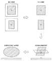
図7は、第1の実施形態に係るX線画像診断装置10が、ステップST007からステップST013まで実行する処理の内容の概略を示した説明図である。 FIG. 7 is an explanatory diagram showing an outline of the contents of processing executed by the X-ray image
図7に示すように、第1の実施形態に係るX線画像診断装置10は、血管領域モデル生成部100において、複数の造影画像のそれぞれから、それぞれの2次元血管領域を特定し、その2次元血管領域のそれぞれの重心位置を特定する。次に、血管領域モデル生成部100は、2次元血管領域のそれぞれのサイズを補正し、天板29a上の空間的な位置にそれぞれ3次元的な領域を特定することによって、立体モデルである楕円体により患者Pの仮想的な3次元の血管領域を特定する。 As shown in FIG. 7, in the X-ray image
なお、血管領域モデル生成部100の楕円体形成部104では、患者Pの3次元の血管領域を仮想的な楕円体で特定するようになっているが、本実施形態は楕円体に限定されるものではない。例えば、2次元血管領域における形状から略楕円体を特定してもよく、また、血管領域の形態に類似した3次元で構成される略立方体や略直方体により3次元の血管領域を特定してもよい。 Note that the
次に、X線画像診断装置10のDF装置12は、患者Pの血管領域の投影画像を生成する(ステップST015)。例えば、照射領域特定部110は、ステップST013において特定した立体モデルと、患者Pを照射する照射位置情報を含むシステム位置情報とに基づいて、楕円形の立体モデルに照射される投影画像を生成する。 Next, the
ここで、投影画像とは、2次元の画像として立体的に表示される3次元画像(rendering画像)のことをいうものとする。なお、投影画像は、一例として3次元画像として表示されるが、本実施形態では3次元画像に限定されるものではなく、2次元画像であってもよい。すなわち、本実施形態では、天板29a上の空間的な位置における患者Pの血管領域を示す立体モデルまたは2次元モデルを、2次元平面の情報に投影した画像であれば、投影画像として適用することができる。 Here, the projected image refers to a three-dimensional image (rendering image) displayed stereoscopically as a two-dimensional image. The projected image is displayed as a three-dimensional image as an example, but is not limited to a three-dimensional image in the present embodiment, and may be a two-dimensional image. In other words, in the present embodiment, if a three-dimensional model or a two-dimensional model showing a blood vessel region of the patient P at a spatial position on the
そして、X線画像診断装置10のDF装置12は、照射位置情報を使用して、患者PにX線を照射するCアーム26のアーム角度、SIDおよびFOVの変更に伴って、リアルタイムに投影画像を生成する。また、DF装置12は、患者位置情報において、天板29a上に関する情報(カテーテルテーブルの高さや厚みに関する情報など)や天板29aの傾き(例えば、いわゆる長手チルトや横手チルトなど)に関する情報が変更された場合、その都度、リアルタイムに投影画像を生成する。 Then, the
X線画像診断装置10のDF装置12は、生成した投影画像の照射領域を特定する(ステップST017)。例えば、照射領域特定部110は、投影画像の血管領域の外枠を患者Pの照射領域として特定する。照射領域特定部110は、変更可能なシステム位置情報に基づいて、特定した立体モデルの投影画像を生成することができるので、投影画像の血管領域の外枠により、患者Pの照射領域として特定することができる。 The
なお、この投影画像は、表示装置54に表示される必要はないが、システム位置情報の変更に伴い立体モデルから投影画像を生成するため、リアルタイムに表示する機能を設けることにより、生成された投影画像を患者Pの造影画像とともに表示することができる。この場合、生成された投影画像を、バーチャルコリメータとして表示することができる。 Although this projection image does not need to be displayed on the
次に、X線画像診断装置10のDF装置12は、X線絞りを制御して、X線の照射範囲を調整し、X線照射装置27により患者Pに照射する(ステップST019)。例えば、照射範囲調整部120は、コントローラ30を介して、X線照射装置27が有するX線絞りを制御することにより、特定された照射領域にX線を照射するように、X線の照射範囲を調整する。この場合、ステップST017において特定した照射領域以外の領域は、X線を遮蔽することができる。 Next, the
また、DF装置12の照射範囲調整部120は、コントローラ30を介して、X線照射装置27が有する補償フィルタを用いてもよい。この場合、照射範囲調整部120は、特定された照射領域以外の領域への照射を制限するとともに、投影画像の血管領域の形状に合わせてX線を減衰させることができる。 The irradiation
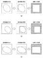
図8は、第1の実施形態に係るX線画像診断装置10が、ステップST015からステップST019まで実行する処理の内容の概略を示した説明図である。 FIG. 8 is an explanatory diagram showing an outline of the contents of the processing executed by the X-ray image
図8に示すように、第1の実施形態に係るX線画像診断装置10は、ステップST013において特定した楕円体による立体モデルに基づいて、投影画像を生成して、その投影画像の血管領域に外接する四角形領域を照射領域として特定することを示している。DF装置12の照射範囲調整部120は、投影画像の血管領域に外接する四角形領域にX線絞りを制御することにより、特定した照射領域の外側へのX線を遮蔽することができる。 As shown in FIG. 8, the X-ray image
これにより、本実施形態では、患者Pに対して照射される照射線量を、低減させることができる。なお、X線を患者Pに照射する処理は、低線量の透視でも高線量の撮影でも、同様に適用することができる。 Thereby, in this embodiment, the irradiation dose irradiated with respect to the patient P can be reduced. The process of irradiating the patient P with X-rays can be similarly applied to both low-dose fluoroscopy and high-dose imaging.
また、図8では、図8(a)から図8(c)として、照射位置情報やシステム位置情報が変更されると、その都度、投影画像が生成されることを示している。例えば、X線画像診断装置10は、患者位置情報が変更された場合はシステム位置情報も同時に変更されるので、図8(a)から図8(b)へ、または図8(b)から図8(c)へと、その都度、自動的に立体モデルの投影画像を生成し、自動的に照射領域のX線絞り制御を行うことを示している。 FIG. 8 shows that a projection image is generated each time the irradiation position information and the system position information are changed, as shown in FIGS. 8A to 8C. For example, in the X-ray
なお、仮想的な立体モデルは、一度生成されると、その仮想的な立体モデルを再生成や変更することなく、継続して投影画像の生成に用いることができる。 Note that once the virtual stereo model is generated, the virtual stereo model can be continuously used to generate a projection image without regenerating or changing the virtual stereo model.
本実施形態に係るX線画像診断装置10は、X線を照射中は、照射領域自動制御処理を継続実施するように実行させ、手技が終了したら、照射領域自動制御処理を終了する。 The X-ray image
以上説明したように、第1の実施形態に係るX線画像診断装置10は、DF装置12の血管領域モデル生成部100において、天板29a上の空間的な位置における患者Pの血管領域を特定し、その特定した血管領域を示す仮想的な立体モデルを生成する。また、X線画像診断装置10は、DF装置12の照射領域特定部110において、生成した仮想的な立体モデルと、患者Pを照射する照射位置情報を含むシステム位置情報とに基づいて、システム位置情報に関する情報の変更に連動し、X線の照射範囲を調整する。 As described above, the X-ray
第1の実施形態に係るX線画像診断装置10によれば、照射範囲調整部120により、立体モデルにより特定された照射領域にX線を照射させるように、X線の照射範囲を調整することができるので、検査や治療において患者Pに対してX線を照射する際のシステムの位置や患者の位置情報の変更に連動し、自動的に照射すべき照射領域を特定して、その照射領域にX線を照射させることができる。 According to the X-ray image
これにより、第1の実施形態に係るX線画像診断装置10によれば、不必要なX線照射を回避し、患者Pに対して被曝を低減することができる。また、術者がX線照射を行う際は、術者は、手動で照射位置や患者位置などを設定する必要がないため、患者Pの被曝の低減に伴う負担を軽減することもできる。 Thereby, according to the X-ray image
また、第1の実施形態に係るX線画像診断装置10は、血管領域モデル生成部100の2次元血管領域特定部101により、複数の方向から撮影された患者Pの造影画像のそれぞれから、それぞれの2次元血管領域を特定するようになっていた。第1の実施形態は、これに限定されるものではなく、患者Pに対するX線照射に基づいて得られる透視画像や撮影画像を、ステップST003の造影画像として適用するようにしてもよい。 In addition, the X-ray image
例えば、第1の実施形態に係るX線画像診断装置10は、ステップST019において、患者Pに対して透視または撮影を行うことにより、透視画像または撮影画像を得ることができる。X線画像診断装置10のDF装置12は、得られた透視画像や撮影画像に対し、ステップST003の造影画像として適用することにより、血管領域を形成する楕円体の形状を更新(補正)することできる。 For example, the X-ray
第1の実施形態では、血管領域を決定する際、確認造影を用いた楕円体(仮想的な立体モデル)を特定するようになっていたが、透視画像または撮影画像を楕円体の特定に反映させることにより、血管領域をより高精度に生成することができる。 In the first embodiment, when determining a blood vessel region, an ellipsoid (virtual three-dimensional model) using confirmation contrast imaging is specified. However, a fluoroscopic image or a captured image is reflected in specifying the ellipsoid. By doing so, the blood vessel region can be generated with higher accuracy.
また、ステップST017では、第1の実施形態に係るX線画像診断装置10は、DF装置12の照射領域特定部110において生成した投影画像の照射領域を特定するようになっていたが、本実施形態では、これに限定されるものではない。例えば、DF装置12の照射領域特定部110は、3次元的に関心領域(ROI:Region Of Interest)を投影画像に設定するようにしてもよい。この場合、照射領域特定部110は、この設定された関心領域にX線を照射させるように設定することができる。 In step ST017, the X-ray image
(第2の実施形態)
第2の実施形態では、第1の実施形態に係るX線画像診断装置10のDF装置12の血管領域モデル生成部100において、さらに心拍によって異なる造影画像のそれぞれから2次元血管領域を特定し、2次元血管領域のそれぞれから、3次元の血管領域を特定するようになっている。(Second Embodiment)
In the second embodiment, the blood vessel region
ここで、患者Pの冠動脈は、心拍によって変動するものである。また、呼吸によっても変化する。そのため、造影画像は、心拍や呼吸の位相により血管領域が異なるため、心拍や呼吸に基づいて、マージンを加味した2次元血管領域を特定することができる。 Here, the coronary artery of the patient P varies depending on the heartbeat. It also changes with breathing. Therefore, the contrast image has a different blood vessel region depending on the phase of heartbeat and respiration, so that a two-dimensional blood vessel region with a margin can be specified based on the heartbeat and respiration.
例えば、心拍の拡張期の呼気と、心拍の拡張期の吸気とにおける造影画像を用いて、いずれの血管領域も含まれるように2次元血管領域を特定する。これにより、心拍や呼吸に基づくマージンを加味した2次元血管領域を特定することができる。 For example, a two-dimensional vascular region is specified so as to include any vascular region using contrast images in exhaled breath during the heartbeat diastole and inspiration during the heartbeat diastole. Thereby, it is possible to specify a two-dimensional blood vessel region taking into account a margin based on heartbeat and respiration.
また、造影画像の1カット分をボトムトレース処理し、2次元血管領域を特定するようにすることもできる。例えば、X線画像診断装置10は、患者Pに造影剤を注入し、時系列に沿って複数枚の造影画像を取得する。そして、血管領域モデル生成部100は、取得した複数枚の造影画像から時間方向に沿ってトレースする処理(ボトムトレース処理)を実行し、2次元血管領域を特定するようにしてもよい。 It is also possible to specify the two-dimensional blood vessel region by performing bottom trace processing for one cut of the contrast image. For example, the X-ray image
(第3の実施形態)
第3の実施形態では、第1の実施形態に係るX線画像診断装置10のDF装置12において、血管領域モデル生成部100は、血管領域において血管挿入デバイスの先端を検出し、照射領域特定部110は、照射領域において血管挿入デバイスの先端を検出し、その血管挿入デバイスの先端位置を投影画像に投影するようになっている。(Third embodiment)
In the third embodiment, in the
第3の実施形態では、照射領域特定部110において、血管挿入デバイスの先端位置を投影画像に投影するようになっているため、投影画像における血管挿入デバイスとX線を照射中のライブ画像における血管挿入デバイスとをリアルタイムに比較することができる。この場合において、投影画像における血管挿入デバイスと、X線を照射中のライブ画像における血管挿入デバイスとにズレを検出した場合には、患者Pが天板29a上で動いたと判断し、そのズレを自動的に補正することができる。 In the third embodiment, the irradiation
例えば、第3の実施形態に係るX線画像診断装置10のDF装置12において、ズレを検出した場合には、照射領域特定部110は、天板29a上の仮想的な立体モデルの位置を補正する。そして、照射範囲調整部120は、X線を照射中のライブ画像における血管挿入デバイスと投影画像における血管挿入デバイスとを一致させた状態で、患者Pに照射するX線の照射範囲を調整する。 For example, in the
このように、天板29a上において患者Pが動いた場合でも、第3の実施形態に係るX線画像診断装置10のDF装置12は、自動的にX線の照射領域を補正して、X線の照射範囲を調整することができるので、術者には何らの操作負担を要せずにX線の照射による患者Pへの被曝を低減することができる。 As described above, even when the patient P moves on the
なお、血管挿入デバイスとは、カテーテル、ガイドワイヤー、ステント、バルーンなどが該当する。また、血管挿入デイバスは、患者Pの体内に挿入されるデバイスであればよく、これらに限定されるものではない。 The blood vessel insertion device corresponds to a catheter, a guide wire, a stent, a balloon, or the like. Further, the blood vessel insertion device may be a device inserted into the body of the patient P, and is not limited thereto.
本発明のいくつかの実施形態を説明したが、これらの実施形態は、例として提示したものであり、発明の範囲を限定することは意図していない。これら実施形態は、その他の様々な形態で実施されることが可能であり、発明の要旨を逸脱しない範囲で、種々の省略、置き換え、変更を行うことができる。これら実施形態やその変形は、発明の範囲や要旨に含まれると同様に、特許請求の範囲に記載された発明とその均等の範囲に含まれるものである。 Although several embodiments of the present invention have been described, these embodiments are presented by way of example and are not intended to limit the scope of the invention. These embodiments can be implemented in various other forms, and various omissions, replacements, and changes can be made without departing from the spirit of the invention. These embodiments and their modifications are included in the scope and gist of the invention, and are also included in the invention described in the claims and the equivalents thereof.
10 X線画像診断装置
11 保持装置
12 DF装置
21 スライド機構
211 Z軸方向レール
212 X軸方向レール
213 台車
23 鉛直軸回転機構
24 懸垂アーム
25 Cアーム回転機構
26 Cアーム
27 X線照射装置
28 検出装置
30 コントローラ
32 駆動制御部
44 入力装置
45 通信制御装置
53 画像データ記憶部
54 表示装置
100 血管領域モデル生成部(領域特定部)
101 2次元血管領域特定部
102 重心位置特定部
103 領域サイズ補正部
104 楕円体形成部
110 照射領域特定部
120 照射範囲調整部DESCRIPTION OF
101 Two-dimensional blood vessel
Claims (13)
Translated fromJapanese特定された前記3次元領域と、前記患者を照射する照射位置情報を含むシステム位置情報とに基づいて、前記システム位置情報に関する情報の変更に連動し、前記X線の照射範囲を調整する照射範囲調整部と、
を備えるX線診断装置。An area specifying unit for specifying a predetermined three-dimensional area of the patient at a spatial position on the top plate based on a plurality of X-ray images taken from at least two directions;
An irradiation range that adjusts the X-ray irradiation range in conjunction with a change in information related to the system position information based on the identified three-dimensional region and system position information including irradiation position information for irradiating the patient An adjustment unit;
An X-ray diagnostic apparatus comprising:
複数の血管造影画像である
請求項1に記載のX線診断装置。The plurality of X-ray images are
The X-ray diagnostic apparatus according to claim 1, wherein the X-ray diagnostic apparatus is a plurality of angiographic images.
前記複数の血管造影画像に基づいて、それぞれ前記患者の血管領域を特定することにより、その特定したそれぞれの前記血管領域を含む立体モデルを生成し、
前記照射範囲調整部は、
生成した前記立体モデルと前記システム位置情報とに基づいて、前記システム位置情報に関する情報の変更に連動し、前記患者に照射される照射領域を特定して、前記X線の前記照射範囲を調整する
請求項2に記載のX線診断装置。The region specifying unit includes:
Based on the plurality of angiographic images, each of the patient's vascular regions is identified to generate a three-dimensional model including the identified vascular regions,
The irradiation range adjustment unit is
Based on the generated three-dimensional model and the system position information, the irradiation area irradiated to the patient is identified and the irradiation range of the X-ray is adjusted in conjunction with the change of the information on the system position information. The X-ray diagnostic apparatus according to claim 2.
前記血管領域の重心位置をそれぞれ特定し、前記患者の中心位置に前記血管領域の重心位置をそれぞれ配置することにより、それぞれの前記血管造影画像のサイズを前記天板上の空間的な位置に変換し、その天板上の空間的な位置のサイズに補正して前記立体モデルを生成する
請求項3に記載のX線診断装置。The region specifying unit includes:
Each centroid position of the vascular region is specified, and the centroid position of the vascular region is arranged at the center position of the patient, thereby converting the size of each angiographic image into a spatial position on the top board. The X-ray diagnostic apparatus according to claim 3, wherein the three-dimensional model is generated by correcting to a spatial position size on the top plate.
前記立体モデルを用いた前記天板上の空間的な位置における楕円体により、前記3次元領域を特定する
請求項3または4に記載のX線診断装置。The region specifying unit includes:
The X-ray diagnostic apparatus according to claim 3, wherein the three-dimensional region is specified by an ellipsoid at a spatial position on the top plate using the three-dimensional model.
前記患者の特徴を示す患者特徴情報と前記システム位置情報とに基づいて、前記立体モデルを生成する
請求項3から5のいずれか1項に記載のX線診断装置。The region specifying unit includes:
The X-ray diagnostic apparatus according to claim 3, wherein the three-dimensional model is generated based on patient characteristic information indicating the characteristics of the patient and the system position information.
前記照射範囲調整部は、
前記システム位置情報に含まれる前記患者位置情報と前記照射位置情報とに基づいて、前記患者位置情報と前記照射位置情報との変更に連動する前記立体モデルにより前記患者に照射される前記照射領域を特定し、前記X線の前記照射範囲を調整する
請求項3から6のいずれか1項に記載のX線診断装置。The system position information includes patient position information indicating the position of the patient;
The irradiation range adjustment unit is
Based on the patient position information and the irradiation position information included in the system position information, the irradiation region irradiated on the patient by the three-dimensional model interlocked with the change between the patient position information and the irradiation position information The X-ray diagnostic apparatus according to any one of claims 3 to 6, wherein the X-ray irradiation range is specified and the irradiation range of the X-ray is adjusted.
前記システム位置情報の変更に伴って、前記立体モデルの投影画像を生成するとともに、その投影画像の血管領域の外枠を前記患者に照射される前記照射領域として特定し、
X線絞りを制御することにより、特定された前記照射領域に前記X線を照射するように、前記X線の前記照射範囲を調整する
請求項3から7のいずれか1項に記載のX線診断装置。The irradiation range adjustment unit is
Along with the change of the system position information, the projection image of the three-dimensional model is generated, and the outer frame of the blood vessel region of the projection image is specified as the irradiation region irradiated to the patient,
The X-ray according to any one of claims 3 to 7, wherein the irradiation range of the X-ray is adjusted so that the specified irradiation region is irradiated with the X-ray by controlling an X-ray diaphragm. Diagnostic device.
前記システム位置情報の変更に伴って、前記立体モデルの投影画像を生成するとともに、その投影画像から前記患者に照射される前記照射領域を特定し、
補償フィルタを用いて前記X線を減衰させる
請求項3から8のいずれか1項に記載のX線診断装置。The irradiation range adjustment unit is
Along with the change in the system position information, a projection image of the three-dimensional model is generated, and the irradiation region irradiated on the patient is specified from the projection image,
The X-ray diagnostic apparatus according to claim 3, wherein the X-ray is attenuated using a compensation filter.
心拍や呼吸の変化によって異なる複数の前記X線画像から、前記3次元領域を特定する
請求項1から8のいずれか1項に記載のX線診断装置。The region specifying unit includes:
The X-ray diagnostic apparatus according to any one of claims 1 to 8, wherein the three-dimensional region is specified from a plurality of the X-ray images that differ depending on changes in heartbeat and respiration.
前記立体モデルにおいて血管挿入デバイスの先端を検出し、
前記照射範囲調整部は、
前記照射領域において前記血管挿入デバイスの先端を検出し、その血管挿入デバイスの先端位置を前記投影画像に投影しつつ、その投影画像における前記血管挿入デバイスと前記X線を照射中のライブ画像における血管挿入デバイスとを比較して、位置のズレを検出した場合には、前記立体モデルの位置を補正し、
前記X線を照射中のライブ画像における前記血管挿入デバイスと前記投影画像における前記血管挿入デバイスとを一致させた状態で、前記照射領域に前記X線を照射するように、前記X線の前記照射範囲を調整する
請求項8または9に記載のX線診断装置。The region specifying unit includes:
Detecting the tip of the blood vessel insertion device in the three-dimensional model;
The irradiation range adjustment unit is
The tip of the blood vessel insertion device is detected in the irradiation region, and the blood vessel insertion device in the projection image and the blood vessel in the live image being irradiated with the X-ray are projected onto the projection image while projecting the tip position of the blood vessel insertion device on the projection image. When the positional deviation is detected by comparing with the insertion device, the position of the three-dimensional model is corrected,
The irradiation of the X-rays is performed so that the X-rays are irradiated to the irradiation region in a state where the blood vessel insertion device in the live image being irradiated with the X-rays is matched with the blood vessel insertion device in the projection image. The X-ray diagnostic apparatus according to claim 8 or 9, wherein the range is adjusted.
前記照射位置情報において、アーム角度、SID、FOVの少なくともいずれか1つを含む
請求項1から10のいずれか1項に記載のX線診断装置。The system location information is
The X-ray diagnostic apparatus according to claim 1, wherein the irradiation position information includes at least one of an arm angle, SID, and FOV.
前記患者位置情報において、カテーテルテーブル高さ、長手チルト、横手チルトの少なくともいずれか1つを含む
請求項1から11のいずれか1項に記載のX線診断装置。The system location information is
The X-ray diagnostic apparatus according to claim 1, wherein the patient position information includes at least one of a catheter table height, a longitudinal tilt, and a lateral hand tilt.
Priority Applications (2)
| Application Number | Priority Date | Filing Date | Title |
|---|---|---|---|
| JP2015080059AJP2016198262A (en) | 2015-04-09 | 2015-04-09 | X-ray diagnostic apparatus |
| US15/086,649US10441239B2 (en) | 2015-04-09 | 2016-03-31 | X-ray diagnostic apparatus, and method of adjusting irradiation range of X-ray diagnostic apparatus |
Applications Claiming Priority (1)
| Application Number | Priority Date | Filing Date | Title |
|---|---|---|---|
| JP2015080059AJP2016198262A (en) | 2015-04-09 | 2015-04-09 | X-ray diagnostic apparatus |
Publications (1)
| Publication Number | Publication Date |
|---|---|
| JP2016198262Atrue JP2016198262A (en) | 2016-12-01 |
Family
ID=57112214
Family Applications (1)
| Application Number | Title | Priority Date | Filing Date |
|---|---|---|---|
| JP2015080059APendingJP2016198262A (en) | 2015-04-09 | 2015-04-09 | X-ray diagnostic apparatus |
Country Status (2)
| Country | Link |
|---|---|
| US (1) | US10441239B2 (en) |
| JP (1) | JP2016198262A (en) |
Families Citing this family (13)
| Publication number | Priority date | Publication date | Assignee | Title |
|---|---|---|---|---|
| US10210956B2 (en) | 2012-10-24 | 2019-02-19 | Cathworks Ltd. | Diagnostically useful results in real time |
| IL263065B2 (en) | 2016-05-16 | 2024-08-01 | Cathworks Ltd | System for vascular assessment |
| EP3461253B1 (en) | 2016-05-16 | 2023-08-09 | Cathworks Ltd. | Selection of vascular paths from images |
| CN107518907A (en)* | 2016-06-22 | 2017-12-29 | 沈阳东软医疗系统有限公司 | A kind of medical imaging device and its frame |
| WO2018165478A1 (en)* | 2017-03-09 | 2018-09-13 | Cathworks Ltd. | Shell-constrained localization of vasculature |
| US11191504B2 (en)* | 2018-07-31 | 2021-12-07 | Canon Medical Systems Corporation | X-ray diagnosis apparatus comprising a blood vessel running information acquiring function, a position specification function, and a diaphragm control function |
| JP7532402B2 (en) | 2019-04-01 | 2024-08-13 | キャスワークス リミテッド | Method and apparatus for angiographic image selection - Patents.com |
| EP4033964B1 (en) | 2019-09-23 | 2025-04-09 | Cathworks Ltd. | Methods, apparatus, and system for synchronization between a three-dimensional vascular model and an imaging device |
| US11980493B2 (en)* | 2020-07-31 | 2024-05-14 | Ricoh Company, Ltd. | Image processing apparatus, imaging system, image processing method, and storage medium |
| US11311264B2 (en) | 2020-09-11 | 2022-04-26 | Wisconsin Alumni Research Foundation | Computed tomography machine for interventional use |
| US12315076B1 (en) | 2021-09-22 | 2025-05-27 | Cathworks Ltd. | Four-dimensional motion analysis of a patient's coronary arteries and myocardial wall |
| JP2025506500A (en) | 2022-02-10 | 2025-03-11 | キャスワークス リミテッド | Systems and methods for machine learning based sensor analysis and vascular tree segmentation |
| CN115024740B (en)* | 2022-08-11 | 2022-10-25 | 晓智未来(成都)科技有限公司 | Virtual radiation field display method for common X-ray photography |
Family Cites Families (6)
| Publication number | Priority date | Publication date | Assignee | Title |
|---|---|---|---|---|
| JP4473358B2 (en)* | 1999-01-21 | 2010-06-02 | 株式会社東芝 | Diagnostic equipment |
| US20040066885A1 (en)* | 2002-07-08 | 2004-04-08 | Kabushiki Kaisha Toshiba | X-ray diagnosis apparatus |
| EP1430835B1 (en)* | 2002-12-17 | 2011-11-16 | Kabushiki Kaisha Toshiba | System for peripheral X-ray angiography |
| US7697740B2 (en)* | 2005-10-21 | 2010-04-13 | Kabushiki Kaisha Toshiba | Medical image processing system and medical image processing method |
| JP2007301228A (en) | 2006-05-12 | 2007-11-22 | Toshiba Corp | X-ray CT apparatus and control method thereof |
| WO2009116465A1 (en)* | 2008-03-21 | 2009-09-24 | 株式会社 日立メディコ | Medical image display device and medical image display method |
- 2015
- 2015-04-09JPJP2015080059Apatent/JP2016198262A/enactivePending
- 2016
- 2016-03-31USUS15/086,649patent/US10441239B2/enactiveActive
Also Published As
| Publication number | Publication date |
|---|---|
| US20160296195A1 (en) | 2016-10-13 |
| US10441239B2 (en) | 2019-10-15 |
Similar Documents
| Publication | Publication Date | Title |
|---|---|---|
| US10441239B2 (en) | X-ray diagnostic apparatus, and method of adjusting irradiation range of X-ray diagnostic apparatus | |
| JP6625347B2 (en) | X-ray angiography device | |
| JP7211230B2 (en) | X-ray fluoroscope | |
| CN107307877B (en) | X-ray diagnostic equipment | |
| JP6466132B2 (en) | Medical image processing apparatus and X-ray image diagnostic apparatus | |
| US10743832B2 (en) | X-ray beam shaping | |
| JP5238296B2 (en) | X-ray apparatus and rotational imaging method | |
| US20190239859A1 (en) | Medical image diagnostic apparatus and x-ray irradiation controller | |
| US11464474B2 (en) | Medical image processing apparatus, X-ray diagnostic apparatus, and medical image processing method | |
| JP5342628B2 (en) | X-ray imaging device | |
| JP7140251B2 (en) | radiography equipment | |
| US12133747B2 (en) | Computer-assisted tomography system | |
| JP6287719B2 (en) | X-ray equipment | |
| JP7199958B2 (en) | Angio CT device | |
| JP7160529B2 (en) | MEDICAL IMAGE PROCESSING APPARATUS, X-RAY DIAGNOSTIC APPARATUS, AND MEDICAL IMAGE PROCESSING METHOD | |
| US20240362783A1 (en) | Medical image processing device, treatment system, medical image processing method, and storage medium | |
| JP6906945B2 (en) | X-ray diagnostic system | |
| JP7471792B2 (en) | X-ray diagnostic equipment | |
| JP2017196427A (en) | X-ray diagnostic equipment | |
| US11426136B2 (en) | X-ray diagnostic system and medical image diagnostic system | |
| JP2020099583A (en) | Medical information processing apparatus and X-ray diagnostic apparatus | |
| JP2020096751A (en) | X-ray diagnostic apparatus | |
| JP2019042389A (en) | Radiation therapy apparatus and patient positioning apparatus |