JP2016194530A - Earthquake warning system - Google Patents
Earthquake warning systemDownload PDFInfo
- Publication number
- JP2016194530A JP2016194530AJP2016157382AJP2016157382AJP2016194530AJP 2016194530 AJP2016194530 AJP 2016194530AJP 2016157382 AJP2016157382 AJP 2016157382AJP 2016157382 AJP2016157382 AJP 2016157382AJP 2016194530 AJP2016194530 AJP 2016194530A
- Authority
- JP
- Japan
- Prior art keywords
- signal
- sensor
- seismic
- sensors
- epicenter
- Prior art date
- Legal status (The legal status is an assumption and is not a legal conclusion. Google has not performed a legal analysis and makes no representation as to the accuracy of the status listed.)
- Pending
Links
Images


Classifications
- G—PHYSICS
- G01—MEASURING; TESTING
- G01V—GEOPHYSICS; GRAVITATIONAL MEASUREMENTS; DETECTING MASSES OR OBJECTS; TAGS
- G01V1/00—Seismology; Seismic or acoustic prospecting or detecting
- G01V1/01—Measuring or predicting earthquakes
- G—PHYSICS
- G08—SIGNALLING
- G08B—SIGNALLING OR CALLING SYSTEMS; ORDER TELEGRAPHS; ALARM SYSTEMS
- G08B21/00—Alarms responsive to a single specified undesired or abnormal condition and not otherwise provided for
- G08B21/02—Alarms for ensuring the safety of persons
- G08B21/10—Alarms for ensuring the safety of persons responsive to calamitous events, e.g. tornados or earthquakes
- G—PHYSICS
- G01—MEASURING; TESTING
- G01V—GEOPHYSICS; GRAVITATIONAL MEASUREMENTS; DETECTING MASSES OR OBJECTS; TAGS
- G01V2210/00—Details of seismic processing or analysis
- G01V2210/10—Aspects of acoustic signal generation or detection
- G01V2210/12—Signal generation
- G01V2210/123—Passive source, e.g. microseismics
- G01V2210/1232—Earthquakes
- G—PHYSICS
- G01—MEASURING; TESTING
- G01V—GEOPHYSICS; GRAVITATIONAL MEASUREMENTS; DETECTING MASSES OR OBJECTS; TAGS
- G01V2210/00—Details of seismic processing or analysis
- G01V2210/60—Analysis
- G01V2210/65—Source localisation, e.g. faults, hypocenters or reservoirs
- G—PHYSICS
- G01—MEASURING; TESTING
- G01V—GEOPHYSICS; GRAVITATIONAL MEASUREMENTS; DETECTING MASSES OR OBJECTS; TAGS
- G01V2210/00—Details of seismic processing or analysis
- G01V2210/70—Other details related to processing
- G01V2210/72—Real-time processing
Landscapes
- Life Sciences & Earth Sciences (AREA)
- Physics & Mathematics (AREA)
- Environmental & Geological Engineering (AREA)
- Geology (AREA)
- General Life Sciences & Earth Sciences (AREA)
- General Physics & Mathematics (AREA)
- Business, Economics & Management (AREA)
- Emergency Management (AREA)
- Engineering & Computer Science (AREA)
- Remote Sensing (AREA)
- Acoustics & Sound (AREA)
- Geophysics (AREA)
- Geophysics And Detection Of Objects (AREA)
Abstract
Translated fromJapaneseDescription
Translated fromJapanese[関連出願の相互参照]
本願は、“Earthquake Warning System”との名称で2010年12月17日に出願された米国仮出願第61/424165号の優先権を主張する。また、本願は、“Rapid,Reliable Networked Earthquake Warning System”との名称で2010年12月17日に出願された米国仮出願第61/424193号の優先権も主張する。本願は、“Rapid,Reliable Earthquake Warning System”との名称で2010年12月17日に出願された米国仮出願第61/424175号の優先権も主張する。[Cross-reference of related applications]
This application claims priority to US Provisional Application No. 61 / 424,165, filed Dec. 17, 2010, under the name “Earthquake Warning System”. This application also claims the priority of US Provisional Application No. 61 / 424,193, filed Dec. 17, 2010 under the name “Rapid, Reliable Networked Earthquake Warning System”. This application also claims the priority of US Provisional Application No. 61 / 424,175, filed Dec. 17, 2010, under the name “Rapid, Reliable Earthquake Warning System”.
上記出願は全て、その全体が参照として本願に組み込まれる。 All of the above applications are incorporated herein by reference in their entirety.
[参照による組み込み]
本明細書中で言及される全ての公報及び特許出願は、それら各公報又は特許出願が個別に参照として組み込まれるように指摘されている場合と同程度において本願において参照として組み込まれる。[Incorporation by reference]
All publications and patent applications mentioned in this specification are hereby incorporated by reference to the same extent as if each publication or patent application was pointed out to be incorporated by reference individually.
本願は、一般的に地震の検出及び警報に関する。特に、本願は、マグニチュードを推定せずに地震の震度を求めること、単一ステーションで震央位置を推定すること、感知される信号のノイズを低下させることに関する。 This application relates generally to earthquake detection and alarming. In particular, this application relates to determining seismic intensity without estimating magnitude, estimating epicenter location at a single station, and reducing noise in the sensed signal.
地震警報システム(EWS,Earthquake Warning System)は、危険な揺れの前に、警報を発するための地震の地動の早期検出及び特性評価によるものである。大抵の既存のEWSは、P派の到達を感知して、P波を分析して、P波の特性と歴史上の地震のマグニチュードとの間の経験的関係を介して現在進行中の事象のマグニチュードを推定することによって、地震の開始を検出するように設計されている。複数のステーションにおけるP波の到達時間を用いて、その事象の震央を推定する。そして、推定されたマグニチュード及び震央は、マグニチュードと震央距離と震度との間の経験的関係によって、差し迫った地動の震度を推定するのに用いられる。P波に基づいたEWSが提供することができる警告時間は、震央からの距離に比例する。経験則によると、8km毎に1秒である。 The earthquake warning system (EWS, Earthquake Warning System) is based on early detection and characterization of earthquake ground motion to issue an alarm before dangerous shaking. Most existing EWSs sense the arrival of the P faction, analyze the P-wave, and identify the events currently under way through an empirical relationship between the characteristics of the P-wave and the magnitude of historical earthquakes. Designed to detect the onset of earthquakes by estimating magnitude. The epicenter of the event is estimated using the arrival times of P waves at multiple stations. The estimated magnitude and epicenter are then used to estimate the seismic intensity of the impending ground motion by an empirical relationship between the magnitude, epicenter distance and seismic intensity. The warning time that EWS based on P-waves can provide is proportional to the distance from the epicenter. A rule of thumb is 1 second every 8 km.
この方法は、P波からのマグニチュードの推定とマグニチュードからの震度の推定の間の不確実性の増大をもたらす。また、時間は、地震警報において重要であり、この二段階推定法は、計算時間を必要以上に増大させる。この推定における測定の不確実性は、典型的に、推定自体と共には報告されず、これは、不連続な応答挙動をもたらし、推定された地動の僅かな変化が、特定の閾値を超えたために、全く異なる応答をもたらすことになる。例えば、ある任意スケールにおいて、5以上の推定震度に対して、警報が発せられるとする。この推定における不確実性を報告しないと、4.999の推定震度に対する応答は、5.000の推定震度に対する応答とは全く異なる。後者の場合、警報が発せられるが、前者の場合には、非常に似た地震の推定にもかかわらず、警報が発せられない。しかしながら、二つの推定震度がそれぞれの誤差範囲のために統計的には区別できない場合、警報又は推定に対する他の応答は異なってはならない。 This method results in increased uncertainty between magnitude estimation from P-waves and seismic intensity estimation from magnitude. Time is also important in earthquake warnings, and this two-stage estimation method increases the computation time more than necessary. The measurement uncertainty in this estimate is typically not reported with the estimate itself, which results in discontinuous response behavior, because slight changes in estimated ground motion have exceeded a certain threshold Will give a completely different response. For example, it is assumed that an alarm is issued for an estimated seismic intensity of 5 or more at an arbitrary scale. Without reporting the uncertainty in this estimation, the response to an estimated seismic intensity of 4.999 is quite different from the response to an estimated seismic intensity of 5.000. In the latter case, a warning is issued, but in the former case, a warning is not issued in spite of a very similar earthquake estimate. However, if the two estimated seismic intensities are not statistically distinguishable due to their respective error ranges, other responses to warnings or estimates should not be different.
他のEWSは、強力な衝撃波の警報を提供するために十分な距離におけるS波の検出によるものである。S波はP波よりも遅く伝わるので、可能な警告時間は少ないが、震度の推定における不確実性は、S波の直接測定を待つことによって、或る程度低下する。この方法が最も良く機能するのは、震央候補が人口密集地から十分に離れていて、リモートセンサーがS波を待つ時間を与えることができて、それでもなお有用な警報を提供することができる場合である。このようなシステムは、沿岸起源の地震をメキシコシティに警告する。 Another EWS relies on the detection of S waves at a distance sufficient to provide a powerful shock wave alarm. Since the S wave travels slower than the P wave, there is less possible warning time, but the uncertainty in seismic intensity estimation is reduced to some extent by waiting for a direct measurement of the S wave. This method works best when the epicenter candidate is far enough from the densely populated area, can give the remote sensor time to wait for the S wave and still provide useful alerts. It is. Such a system warns Mexico City of earthquakes of coastal origin.
EWSの設計は多様であるが、一般的にはスタンドアローン型とネットワーク型に分けることができる。スタンドアローン型EWSは、局所的感知デバイスを用いて、地震が始まったかどうか、また、防護行動を開始するのに足る震度であるかどうかについての極めて局所的な決定を行う。こうしたシステムはP波の到達に対して早期に反応することができるが、誤判定の問題があり得る。S波の検出によるスタンドアローン型デバイスは、一般的に、地震スイッチと呼ばれていて、深刻な揺れが始まった後においてのみ応答するので、地震の警報を提供することができないが、損害を防ぐための活動を開始させることができる。 There are various EWS designs, but in general, it can be divided into a stand-alone type and a network type. Stand-alone EWS uses a local sensing device to make a very local decision as to whether an earthquake has started and whether the seismic intensity is sufficient to initiate a protective action. Such a system can react early to the arrival of the P wave, but there can be a problem of misjudgment. Stand-alone devices with S-wave detection are commonly referred to as seismic switches and respond only after a severe shake begins, so they cannot provide earthquake alarms but prevent damage Activities can be started.
ネットワーク型EWSは、震央候補の近くにおいて、その震央候補までの距離を最少にするように配置された地理的に分散した複数のサイトを備える。地震が発生すると、P波は外側に伝わって、まず最も近いサイトに到達し、そのサイトが、影響を受ける他の全てのサイトに信号を送信する。EWSが提供することのできる警告時間は、各スタンドアローン型サイトで可能な警告時間よりも良くなる。何故ならば、最も近いサイトからの信号が、P波の到達のかなり前に他のサイトに到達するからである。 The network type EWS includes a plurality of geographically dispersed sites arranged near the epicenter candidate so as to minimize the distance to the epicenter candidate. When an earthquake occurs, the P-waves travel outward and first reach the nearest site, which sends a signal to all other affected sites. The warning time that EWS can provide is better than the warning time possible at each stand-alone site. This is because the signal from the closest site reaches the other site long before the arrival of the P wave.
スタンドアローン型システムの一般的な警告時間は以下の式で与えられ:
t警告‐スタンドアローン=ts−tp
ここで、tsは、震源からサイトまでのS波の走時であり、tpは、震源からサイトまでのP波の走時である。これらの走時は
ts=d/Vs
tp=d/Vp
であり、ここで、dは震源からサイトまでの距離であり、VsはS波の速度であり、VpはP波の速度である。ポアソンソリッド(地殻の特性に対する優れた近似)に対しては、
tF=dF/Vp
であり、ここで、tFは、震源から第一のセンサーサイトまでのP波の走時であり、dFは、震源から第一のセンサーサイトまでの距離である。ネットワーク型EWSの警告時間(処理遅延及び通信遅延を無視する)は、
t警告‐EWS=ts−tF
であり、警告の改善比は、
改善比=2.4
である。A typical warning time for a stand-alone system is given by:
tWARNING - stand-alone =t s -tp
Here, ts is when run of S waves from the epicenter to the site, tp is the time run of the P wave from the epicenter to the site. These travel times are ts = d / Vs
tp = d / Vp
Where d is the distance from the epicenter to the site, Vs is the velocity of the S wave, and Vp is the velocity of the P wave. For Poisson solids (an excellent approximation to crust properties)
tF = dF / Vp
Where tF is the travel time of the P wave from the epicenter to the first sensor site, and dF is the distance from the epicenter to the first sensor site. Network type EWS warning time (ignoring processing delay and communication delay) is
twarning-EWS = ts -tF
And the warning improvement ratio is
Improvement ratio = 2.4
It is.
一般的に、2.4のオーダの改善比は実際には考えられない。何故ならば、上記分析においては、多様なシステムの遅延及び震源の深さが無視されているからである。それでも、顕著な改善があるのが、ネットワーク型EWSが好まれる設計となる理由の一つである。 In general, an improvement ratio of the order of 2.4 is not actually considered. This is because, in the above analysis, various system delays and source depths are ignored. Nevertheless, the significant improvement is one of the reasons why networked EWS is preferred.
スタンドアローン型EWSシステムには、アルゴリズムエラー、電気ノイズ、損害、部品の故障等の要因によって生じる多数の誤判定源が存在するが、最も一般的な誤判定源は、文化的ノイズ、つまり人為的な振動であり、これは、地震事象と区別することが難しく、地震の分析アルゴリズムを混乱させる。複数のサイトからの報告を待つことによって誤判定の可能性を減らすことは、信頼性のある警告時間と引き換えになる。 In a stand-alone EWS system, there are a number of misjudgment sources caused by factors such as algorithm errors, electrical noise, damage, component failures, etc. The most common misjudgment source is cultural noise, or human artifacts. Vibration, which is difficult to distinguish from seismic events and disrupts seismic analysis algorithms. Reducing the possibility of misjudgment by waiting for reports from multiple sites comes at the cost of a reliable warning time.
ネットワーク型EWSは、スタンドアローン型EWSよりも良い誤判定性能を提供する可能性がある。誤判定の問題に対処するため、複数のサイトが地震を報告するまで、警報を発する決定を引き延ばすことができる。より多くのサイトが地震を報告するほど、より自信を持って、コストのかかる行動を開始することができる。しかしながら、複数のサイトを待つのに費やされる時間は、防護行動を完了するのに利用可能は時間を減らす。時間は、命を守り、財産の損失を減らすために非常に価値のあるものである。しかしながら、もしも複数のサイトが報告するのを待つことによって可能になる信頼性を、たった一つのサイトで達成することができるならば、EWSの性能は増強されて、2.4の改善比に近くなるのに役立つ。 Network-type EWS may provide better misjudgment performance than stand-alone EWS. To address the issue of misjudgment, the decision to issue an alarm can be postponed until multiple sites report an earthquake. The more sites report an earthquake, the more confident and costly action can be initiated. However, the time spent waiting for multiple sites reduces the time available to complete the protective action. Time is very valuable to save lives and reduce property losses. However, if the reliability that is possible by waiting for multiple sites to report can be achieved at only one site, the performance of EWS is enhanced, close to an improvement ratio of 2.4. Help to be.
EWSの価値は、怪我を減らして損傷から資産を保護する性能によって測られる。誤判定を防止して、迅速に反応し、防護行動を完了するのに可能な限り多くの時間を提供する信頼できるEWSは、地震の危険性を有する者にとって非常に価値のあるものである。 The value of EWS is measured by its ability to reduce injury and protect assets from damage. A reliable EWS that prevents misjudgment, reacts quickly, and provides as much time as possible to complete protective actions is very valuable for those at risk of earthquakes.
一般的に、一実施形態では、地震事象を検出する方法は、測定位置において少なくとも一つのセンサーを用いて地震事象のP波(第一波,primary wave)を検出するステップと; 検出されたP波の少なくとも一つのパラメータを用いて、地震事象のマグニチュードを決定せずに測定位置における推定ピーク震度を決定するステップと; 地震事象の震央を決定するステップと; 決定された推定ピーク震度と震央からの特定位置の距離とを用いて、特定位置における地震事象の震度を推定するステップとを含む。 In general, in one embodiment, a method for detecting a seismic event comprises detecting a P wave (primary wave) of an earthquake event using at least one sensor at a measurement location; Determining the estimated peak seismic intensity at the measurement location without determining the magnitude of the seismic event using at least one parameter of the wave; determining the epicenter of the seismic event; from the determined estimated peak seismic intensity and epicenter And estimating the seismic intensity of the earthquake event at the specific position using the distance of the specific position.
追加的に又は代替的に、本実施形態及び他の実施形態は、以下の特徴を一つ以上含み得る。 Additionally or alternatively, this and other embodiments can include one or more of the following features.
本方法は、地震事象の震度が閾値を超えた場合に警報を発するステップを更に含むことができる。警報を発するステップは、確率関数として警報を発することを含むことができる。確率関数を、予測値を表す一パラメータと、分布の偏差を表す一パラメータとを用いてエンコードすることができる。 The method may further include issuing an alarm if the seismic intensity of the seismic event exceeds a threshold value. Raising an alarm can include issuing an alarm as a probability function. The probability function can be encoded using one parameter representing the predicted value and one parameter representing the deviation of the distribution.
震央を決定するステップは、その少なくとも一つのセンサーから収集された情報と、他の測定位置にあるセンサーから収集された情報とを用いることを含むことができて、その少なくとも一つのセンサーと他の測定位置にあるセンサーとは通信ネットワークによって接続される。 The step of determining an epicenter can include using information collected from the at least one sensor and information collected from sensors at other measurement locations, the at least one sensor and other The sensor at the measurement position is connected by a communication network.
検出されたP波の少なくとも一つのパラメータを用いて、測定位置における推定ピーク震度を決定するステップは、少なくとも一つのパラメータとピーク地動との間で求められた経験的関係を用いて、ピーク地動を求めることを含むことができる。求められた経験的関係は、以前の地震データに基づいたものであり得る。 The step of determining the estimated peak seismic intensity at the measurement position using at least one parameter of the detected P-wave is to determine the peak ground motion using an empirical relationship determined between at least one parameter and the peak ground motion. Seeking can be included. The empirical relationship sought may be based on previous earthquake data.
少なくとも一つのパラメータは、時間領域又はスペクトル領域における振幅情報を含むことができる。 The at least one parameter can include amplitude information in the time domain or spectral domain.
少なくとも一つのセンサーは、加速度計、GPSセンサー、変位センサー、又は速度センサーを含むことができる。 The at least one sensor can include an accelerometer, a GPS sensor, a displacement sensor, or a speed sensor.
特定位置における地震事象の震度を推定するステップは、ピーク震度と震央からの特定位置の距離との間で求められた経験的関係を用いることを含むことができる。求められた経験的関係は、以前の地震データに基づいたものであり得る。この経験的関係は以下のようになり得て:
少なくとも一つのセンサーを用いて地震事象のP波を検出するステップは、第一のセンサーを用いて第一の信号を取得して、第二のセンサーを用いて第二の信号を取得して、第一の信号及び第二の信号を相関させて、その相関が設定された閾値に合致した場合にだけ第一の信号及び第二の信号が地震事象のP波に対応していると決定することを含むことができる。 The step of detecting the P-wave of the seismic event using at least one sensor acquires a first signal using the first sensor, acquires a second signal using the second sensor, Correlate the first signal and the second signal and determine that the first signal and the second signal correspond to the P wave of the seismic event only if the correlation meets a set threshold. Can be included.
一般的に、一実施形態では、地震事象を検出するためのシステムは、地震事象のP波を検出するように構成された少なくとも二つのセンサーと、制御装置とを含み、その制御装置は、検出されたP波の少なくとも一つのパラメータを用いて、地震事象のマグニチュードを決定せずに、推定ピーク震度を決定し、地震事象の震央を決定して、決定された推定ピーク震度と震央からの特定位置の距離とを用いて特定位置における地震事象の震度を推定するように構成される。 In general, in one embodiment, a system for detecting a seismic event includes at least two sensors configured to detect a P wave of the seismic event and a controller, the controller comprising a Using at least one parameter of the generated P-wave, the estimated peak seismic intensity is determined without determining the magnitude of the seismic event, the epicenter of the seismic event is determined, and the determined estimated peak seismic intensity and identification from the epicenter The seismic intensity of the seismic event at a specific location is estimated using the location distance.
追加的に又は代替的に、本実施形態及び他の実施形態は、以下の特徴を一つ以上含み得る。 Additionally or alternatively, this and other embodiments can include one or more of the following features.
制御装置は、地震事象の震度が閾値を超えた場合に警報を発するように更に構成され得る。制御装置を、確率関数として警報を発するように構成することができる。確率関数を、予測値を表す一パラメータと分布の偏差を表す一パラメータとを用いてエンコードすることができる。 The controller may be further configured to issue an alarm if the seismic intensity of the seismic event exceeds a threshold value. The controller can be configured to issue an alarm as a probability function. The probability function can be encoded with one parameter representing the predicted value and one parameter representing the deviation of the distribution.
少なくとも二つのセンサーは別々の測定位置に存在し得て、それら測定位置が通信ネットワークによって接続される。 At least two sensors can be at different measurement locations, which are connected by a communication network.
制御装置を、少なくとも一つのパラメータとピーク地動との間で求められた経験的関係を用いてピーク地動を決定することによって、検出されたP波の少なくとも一つのパラメータを用いて測定位置における推定ピーク震度を決定するように構成することができる。求められた経験的関係は、以前の地震データに基づいたものであり得る。 The controller determines the peak ground motion using an empirical relationship determined between the at least one parameter and the peak ground motion, thereby using the at least one parameter of the detected P wave to estimate the estimated peak at the measurement position. Can be configured to determine seismic intensity. The empirical relationship sought may be based on previous earthquake data.
少なくとも一つのパラメータは、時間領域又はスペクトル領域における振幅情報であり得る。 The at least one parameter may be amplitude information in the time domain or spectral domain.
少なくとも二つのセンサーのうち少なくとも一つは、加速度計、GPSセンサー、変位センサー、又は速度センサーであり得る。 At least one of the at least two sensors may be an accelerometer, a GPS sensor, a displacement sensor, or a speed sensor.
制御装置を、ピーク震度と震央からの特定位置の距離との間で求められた経験的関係を用いることによって、特定位置における地震事象の震度を推定するように構成することができる。求められた経験的関係は、以前の地震データに基づいたものであり得る。この経験的関係は、以下のようになり得て:
第一のセンサーを、第一の信号を取得するように構成することができ、第二のセンサーを、第二の信号を取得するように構成することができ、制御装置を、第一の信号及び第二の信号を相関させて、その相関が設定された閾値に合致した場合にだけ第一の信号及び第二の信号が地震事象のP波に対応していると決定するように構成することができる。制御装置を、マグニチュード、方向ベクトル、又は到達時間を比較することによって第一の信号及び第二の信号を相関させるように構成することができる。 The first sensor can be configured to acquire a first signal, the second sensor can be configured to acquire a second signal, and the controller can be configured to acquire the first signal. And correlating the second signal and determining that the first signal and the second signal correspond to the P wave of the seismic event only if the correlation meets a set threshold. be able to. The controller can be configured to correlate the first signal and the second signal by comparing magnitude, direction vector, or arrival time.
地震事象を検出する方法は、測定位置において少なくとも二つのセンサー(少なくとも二つのセンサーは500m以下で離れている)を用いて地震事象のP波を検出するステップと; 検出されたP波の少なくとも一つのパラメータを用いて、測定位置における推定ピーク震度を決定するステップと; 測定位置において少なくとも二つのセンサーのみを用いて地震事象の震央を決定するステップと; 決定された推定ピーク震度と震央からの特定位置の距離とを用いて、特定位置における地震事象の震度を推定するステップとを含む。 A method for detecting seismic events includes detecting at least one of the detected P waves using at least two sensors (at least two sensors are separated by 500 m or less) at a measurement location; Determining the estimated peak seismic intensity at the measurement location using two parameters; determining the epicenter of the seismic event using only at least two sensors at the measurement location; identifying the determined estimated peak seismic intensity and epicenter And using the distance of the position to estimate the seismic intensity of the earthquake event at the specific position.
追加的に又は代替的に、本実施形態及び他の実施形態は、以下の特徴を一つ以上含み得る。 Additionally or alternatively, this and other embodiments can include one or more of the following features.
少なくとも二つのセンサーは、200m以下、例えば100m以下等で離れ得る。 The at least two sensors can be separated by 200 m or less, such as 100 m or less.
本方法は、地震事象の震度が閾値を超えた場合に警報を発するステップを更に含み得る。警報を発するステップは、確率関数として警報を発することを含むことができる。確率関数を、予測値を表す一パラメータと分布の偏差を表す一パラメータとを用いてエンコードすることができる。 The method may further include issuing an alarm if the seismic intensity of the seismic event exceeds a threshold value. Raising an alarm can include issuing an alarm as a probability function. The probability function can be encoded with one parameter representing the predicted value and one parameter representing the deviation of the distribution.
少なくとも二つのセンサーを、有線通信ネットワークによって接続することができる。 At least two sensors can be connected by a wired communication network.
少なくとも二つのセンサーのうち少なくとも一つは、加速度計、GPSセンサー、変位センサー、又は速度センサーを含むことができる。 At least one of the at least two sensors can include an accelerometer, a GPS sensor, a displacement sensor, or a velocity sensor.
少なくとも二つのセンサーを用いて地震事象のP波を検出するステップは、第一のセンサーを用いて第一の信号を取得して、第二のセンサーを用いて第二の信号を取得して、第一の信号及び第二の信号を相関させて、その相関が設定された閾値に合致した場合にだけ第一の信号及び第二の信号が地震事象のP波に対応していると決定することを含み得る。第一の信号及び第二の信号を相関させることは、マグニチュード、方向ベクトル、又は到達時間を比較することを含む。 The step of detecting a P wave of an earthquake event using at least two sensors acquires a first signal using a first sensor, acquires a second signal using a second sensor, Correlate the first signal and the second signal and determine that the first signal and the second signal correspond to the P wave of the seismic event only if the correlation meets a set threshold. Can include. Correlating the first signal and the second signal includes comparing magnitude, direction vector, or arrival time.
少なくとも二つのセンサーは同一のものであり得る。 The at least two sensors can be the same.
震央を決定するステップは、緯度及び経度での確率密度関数として震央を決定することを含むことができる。確率密度関数を、回転角、二つの主軸に沿った偏差、緯度及び経度における予測値を表すパラメータを用いてエンコードすることができる。確率密度関数を、方位角及び伏角の情報を用いて決定することができる。本方法は、局所的地質、地域内の他の測定位置の幾何学的形状、他の測定位置の実時間状態についての以前の情報を用いて確率密度関数を調整することを更に含み得る。 Determining the epicenter can include determining the epicenter as a probability density function at latitude and longitude. The probability density function can be encoded using parameters representing predicted values at rotation angle, deviation along two principal axes, latitude and longitude. A probability density function can be determined using azimuth and dip information. The method may further include adjusting the probability density function with previous information about the local geology, the geometry of other measurement locations within the area, and the real-time state of the other measurement locations.
一般的に、一側面において、地震事象を検出するためのシステムは、地震事象のP波を検出するように構成された少なくとも二つのセンサー(少なくとも二つのセンサーは500m以下で離れている)と、制御装置とを含む。制御装置は、検出されたP波の少なくとも一つのパラメータを用いて、推定ピーク震度を決定し、測定位置において少なくとも二つのセンサーのみを用いて地震事象の震央を決定し、決定された推定ピーク震度と震央からの特定位置の距離とを用いて特定位置における地震事象の震度を推定するように構成される。 In general, in one aspect, a system for detecting seismic events includes at least two sensors configured to detect P waves of seismic events (at least two sensors are separated by 500 meters or less); And a control device. The controller determines the estimated peak seismic intensity using at least one parameter of the detected P wave, determines the epicenter of the seismic event using only at least two sensors at the measurement position, and determines the estimated peak seismic intensity determined. And a seismic intensity of the seismic event at the specific position using the distance from the epicenter and the specific position from the epicenter.
少なくとも二つのセンサーは、200m以下、例えば100m以下で離れ得る。 The at least two sensors can be separated by 200 m or less, for example 100 m or less.
制御装置を、地震事象の震度が閾値を超えた場合に警報を発するように更に構成することができる。制御装置を、確率関数として警報を発するように構成することができる。確率関数を、予測値を表す一パラメータと、分布の偏差を表す一パラメータを用いてエンコードすることができる。 The controller can be further configured to issue an alarm if the seismic intensity of the seismic event exceeds a threshold. The controller can be configured to issue an alarm as a probability function. The probability function can be encoded with one parameter representing the predicted value and one parameter representing the deviation of the distribution.
少なくとも二つのセンサーを有線通信ネットワークによって接続することができる。 At least two sensors can be connected by a wired communication network.
少なくとも二つのセンサーのうち少なくとも一つは、加速度計、GPSセンサー、変位センサー、又は速度センサーを備える。 At least one of the at least two sensors comprises an accelerometer, a GPS sensor, a displacement sensor, or a speed sensor.
第一のセンサーを第一の信号を取得するように構成することができて、第二のセンサーを第二の信号を取得するように構成することができる。制御装置を、第一の信号及び第二の信号を相関させて、その相関が設定された閾値に合致した場合にのみ第一の信号及び第二の信号が地震事象のP波に対応していると決定するように構成することができる。第一の信号及び第二の信号を相関させることは、マグニチュード、方向ベクトル、又は到達時間を比較することを含むことができる。 The first sensor can be configured to acquire a first signal and the second sensor can be configured to acquire a second signal. The controller correlates the first signal and the second signal, and the first signal and the second signal correspond to the P wave of the seismic event only when the correlation meets a set threshold value. Can be configured to be determined. Correlating the first signal and the second signal can include comparing magnitudes, direction vectors, or arrival times.
少なくとも二つのセンサーは同一のものであり得る。 The at least two sensors can be the same.
制御装置を、緯度及び経度での確率密度関数として震央を決定することによって、震央を決定するように構成することができる。確率密度関数を、回転角、二つの主軸に沿った偏差、緯度及び経度における予測値を表すパラメータを用いてエンコードすることができる。確率密度関数を、方位角及び伏角の情報を用いて決定することができる。制御装置を、局所的地質、地域内の他の測定位置の幾何学的形状、及び他の測定サイトの実時間状態についての以前の情報を用いて確率密度関数を調整するように更に構成することができる。 The controller can be configured to determine the epicenter by determining the epicenter as a probability density function at latitude and longitude. The probability density function can be encoded using parameters representing predicted values at rotation angle, deviation along two principal axes, latitude and longitude. A probability density function can be determined using azimuth and dip information. Further configuring the controller to adjust the probability density function with previous information about local geology, geometry of other measurement locations within the area, and real-time conditions of other measurement sites Can do.
一般的に、一側面では、地震事象のP波を検出する方法は、第一の位置にある第一のセンサーから第一の地盤振動信号を取得するステップと; 第一の位置から500m以内の第二の位置にある第二のセンサーから第二の地盤振動信号を取得するステップと; 第一の信号及び第二の信号を相関させるステップと; 第一の信号及び第二の信号の相関が設定された閾値に合致する場合にのみ、第一の信号又は第二の信号の少なくとも一つのパラメータを用いて、地震事象の震度を推定するステップとを含む。 In general, in one aspect, a method for detecting a P wave of an earthquake event includes obtaining a first ground vibration signal from a first sensor at a first position; within 500 meters from the first position; Obtaining a second ground vibration signal from a second sensor at a second position; correlating the first signal and the second signal; and correlating the first signal and the second signal Estimating the seismic intensity of the seismic event using at least one parameter of the first signal or the second signal only if the set threshold is met.
追加的に又は代替的に、本実施形態及び他の実施形態は、以下の特徴を一つ以上含み得る。 Additionally or alternatively, this and other embodiments can include one or more of the following features.
第一のセンサーと第二のセンサーの少なくとも一方は加速度計、速度センサー、又は変位センサーである。 At least one of the first sensor and the second sensor is an accelerometer, a speed sensor, or a displacement sensor.
第一の信号及び第二の信号を相関させるステップは、第一の信号及び第二の信号の方向ベクトルの差を計算することを含むことができて、設定された閾値に合致することは、設定された差以下であることを含み得る。第一の信号及び第二の信号を相関させるステップは、第一の信号及び第二の信号の相互相関ピークを計算することを含むことができて、設定された閾値に合致することは、設定された値以下であることを含み得る。第一の信号及び第二の信号を相関させるステップは、第一の信号と第二の信号との間の時間遅延を計算することを含むことができて、設定された閾値に合致することは、設定された差以下であることを含み得る。第一の信号及び第二の信号を相関させるステップは、第一の信号及び第二の信号のマグニチュードの差を計算することを含むことができて、設定された閾値に合致することは、設定された差以下であることを含み得る。 The step of correlating the first signal and the second signal can include calculating a difference between the direction vectors of the first signal and the second signal, and meeting a set threshold is: It may include being less than or equal to the set difference. Correlating the first signal and the second signal can include calculating a cross-correlation peak of the first signal and the second signal, and meeting the set threshold Or less than the value set. The step of correlating the first signal and the second signal can include calculating a time delay between the first signal and the second signal, and meeting a set threshold value May be less than or equal to the set difference. The step of correlating the first signal and the second signal can include calculating a magnitude difference between the first signal and the second signal, and meeting the set threshold Or less than the difference made.
本方法は、100Hz以上、例えば200Hz以上、800Hz以上のサンプリングレートで第一の信号及び第二の信号を取得することを更に含み得る。 The method may further include acquiring the first signal and the second signal at a sampling rate of 100 Hz or higher, such as 200 Hz or higher, 800 Hz or higher.
本方法は、地震事象の震度が閾値を超えた場合に警報を発するステップを更に含みことができる。警報を発するステップは、確率関数として警報を発することを含むことができる。確率関数を、予測値を表す一パラメータと分布の偏差を表す一パラメータとを用いてエンコードすることができる。取得ステップ及び相関ステップを実時間で連続的に繰り返すことができる。 The method may further include issuing an alarm if the seismic intensity of the seismic event exceeds a threshold value. Raising an alarm can include issuing an alarm as a probability function. The probability function can be encoded with one parameter representing the predicted value and one parameter representing the deviation of the distribution. The acquisition step and the correlation step can be repeated continuously in real time.
少なくとも二つのセンサーは200m以下、例えば100m以下等で離れ得る。 At least two sensors can be separated by 200 m or less, such as 100 m or less.
一般的に、一側面では、地震事象を検出するためのシステムは、第一の位置にあり、第一の地盤振動信号を取得するように構成された第一のセンサーと、第一の位置から500m以内の第二の位置にあり、第二の地盤振動信号を取得するように構成された第二のセンサーと、制御装置とを含む。制御装置は、第一の信号及び第二の信号を相関させて、第一の信号及び第二の信号の相関が設定された閾値に合致した場合にのみ、第一の信号又は第二の信号の少なくとも一つのパラメータを用いて、地震事象の震度を推定するように構成される。 In general, in one aspect, a system for detecting seismic events is in a first position, and a first sensor configured to obtain a first ground vibration signal, and a first position A second sensor located at a second position within 500 m and configured to acquire a second ground vibration signal and a control device are included. The control device correlates the first signal and the second signal, and only when the correlation between the first signal and the second signal matches a set threshold value, the first signal or the second signal. The seismic intensity of the seismic event is estimated using at least one parameter.
第一のセンサーと第二のセンサーの少なくとも一方は、加速度計、速度センサー、又は変位センサーであり得る。 At least one of the first sensor and the second sensor can be an accelerometer, a velocity sensor, or a displacement sensor.
制御装置を、第一の信号及び第二の信号の方向ベクトルの差を計算することによって、第一の信号及び第二の信号を相関させるように構成することができて、設定された閾値に合致することは、設定された差以上であることを含み得る。制御装置を、第一の信号及び第二の信号の相互相関ピークを計算することによって第一の信号及び第二の信号を相関させるように構成することができて、設定された閾値に合致することは、設定された値以下であることを含み得る。制御装置を、第一の信号と第二の信号との間の時間遅延を計算することによって第一の信号及び第二の信号を相関させるように構成することができて、設定された閾値に合致することは、設定された差以下であることを含むことができる。制御装置を、第一の信号及び第二の信号のマグニチュードの差を計算することによって、第一の信号及び第二の信号を相関させるように構成することができて、設定された閾値に合致することは、設定された差以下であることを含み得る。 The controller can be configured to correlate the first signal and the second signal by calculating a difference between the direction vectors of the first signal and the second signal, and to a set threshold value. Matching may include greater than or equal to a set difference. The controller can be configured to correlate the first signal and the second signal by calculating a cross-correlation peak of the first signal and the second signal and meet a set threshold. This may include being below a set value. The controller can be configured to correlate the first signal and the second signal by calculating a time delay between the first signal and the second signal, to a set threshold value. Matching can include being below a set difference. The controller can be configured to correlate the first signal and the second signal by calculating the magnitude difference between the first signal and the second signal and meet a set threshold. Doing may include being below a set difference.
第一のセンサー及び第二のセンサーを、100Hz以上、例えば200Hz以上、少なくとも800Hzのサンプリングレートで第一の信号及び第二の信号を取得するように構成することができる。 The first sensor and the second sensor can be configured to acquire the first signal and the second signal at a sampling rate of 100 Hz or higher, such as 200 Hz or higher, at least 800 Hz.
制御装置を、地震事象の震度が閾値を超えた場合に警報を発するように更に構成することができる。制御装置を、確率関数として警報を発するように構成することができる。確率関数を、予測値を表す一パラメータと分布の偏差を表す一パラメータとを用いてエンコードすることができる。 The controller can be further configured to issue an alarm if the seismic intensity of the seismic event exceeds a threshold. The controller can be configured to issue an alarm as a probability function. The probability function can be encoded with one parameter representing the predicted value and one parameter representing the deviation of the distribution.
センサーを、実時間で取得ステップを繰り返すように構成することができて、制御装置を実時間で相関ステップを繰り返すように構成することができる。 The sensor can be configured to repeat the acquisition step in real time, and the controller can be configured to repeat the correlation step in real time.
少なくとも二つのセンサーは、200m以下、例えば100m以下等で離れ得る。 The at least two sensors can be separated by 200 m or less, such as 100 m or less.
本発明の新規特徴は、添付の特許請求の範囲において具体的に記載されている。本発明の特徴及び利点のより良い理解は、本発明の原理が用いられる例示的な実施形態を説明する以下の詳細な説明及び添付図面を参照することによって、得られるものである。 The novel features of the invention are set forth with particularity in the appended claims. A better understanding of the features and advantages of the present invention will be obtained by reference to the following detailed description that sets forth illustrative embodiments, in which the principles of the invention are utilized, and the accompanying drawings of which:
図1を参照すると、ネットワーク型地震警報システムは、少なくとも一つの断層1の近くの震源候補までの距離を最少にするように配置された地理的に分散した複数のサイト又はセンサーサブシステム2を含む。全てのサイトは、通信ネットワークを介して接続されている。地震が震央3において発生すると、P波4が外側に伝わり、最初に最も近いサイト5に到達し、そのサイト5が、影響を受ける他の全てのサイト2に信号を送信する。EWSが提供することのできる警告時間は、各スタンドアローン型サイトで可能な警告時間よりも優れる。何故ならば、最も近いサイト5からの信号が、P波4の到達のかなり前に他のサイト2に到達するからである。 Referring to FIG. 1, a networked seismic alert system includes a plurality of geographically distributed sites or
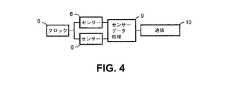
図2を参照すると、地震警報システムは三つのサブシステムから成り、センサーサブシステム2と、分析サブシステム35と、通信サブシステム10とを含む。 Referring to FIG. 2, the earthquake warning system includes three subsystems, and includes a
センサーサブシステム2は、実時間で地動を記録及び報告するために、制御装置と、一つ又は複数の地動センサーを含む。センサーサブシステムは、あらゆるノイズをフィルタリング除去して、収集した信号又はデータを実時間で分析サブシステム35に送る。 The
分析サブシステム35は、センサーサブシステム2及び/又は通信サブシステム10からの入力を受け取って、実時間で震央位置を計算して、差し迫った地動の危険性を推定するように構成された少なくとも一つのコンピュータ又は制御装置を含む。分析サブシステム35は、差し迫った地動の危険性を局所的に(つまり所定のサイトにおいて)且つ地域距離(つまり、データが記憶されたサイト、周辺のステーション、ステーションの無い場所を含む震央の地理的地域内の全ての場所)において計算することができる。更に、分析サブシステム35は、地動及び震央位置の推定における不確実性を計算するように構成される。推定及び不確実性は、分析サブシステム35から通信サブシステム10に送られる。 The
通信サブシステム10は、データを送受信するためのネットワークを含む。更に、通信サブシステム10は、一組のパラメータデータとして推定及び不確実性をエンコードするように構成された少なくとも一つの制御装置又はコンピュータを含む。好ましい実施形態では、パラメータ化は、連続分布関数において予測値及び偏差を表す一対の値の形式をとる、通信システム10は、必要に応じて、パラメータデータを、局所的な地震応答を実現するための局所デバイスに、ピアネットワークとして組織化された地理的地域内の同様のシステムのネットワークに、又は、データを収集して地理的地域における同様のシステムに再分配する地域データセンターに送信する。また、通信サブシステム10は、ピアネットワーク内の他の同様のシステムから、又は地域データセンターから情報を受信して、必要に応じて、データを分析サブシステム35に送る。 The
以下、これら三つのサブシステムの各々について詳述する。 Hereinafter, each of these three subsystems will be described in detail.
〈センサーサブシステム〉
図3を参照すると、各センサーサブシステム2は、局所的制御装置7と、少なくとも一つの軸において地盤振動を測定することができる二つ以上の感知デバイス6とを含む。一実施形態では、通常は、上(U、Z)、北(N)、東(E)を向いた三軸感知デバイスが存在する。感知デバイスは、加速度計、速度センサー、又は変位センサーであり得る。一実施形態では、二つのセンサーが存在し、一方のセンサーが加速度計であり、他方のセンサーが高サンプルレートのGPSセンサーである。他の実施形態では、三つのセンサーが存在し、そのうち二つのセンサーが加速度計であり、残りのセンサーが高サンプルレートのGPSセンサーである。<Sensor subsystem>
Referring to FIG. 3, each
センサーサブシステム2内のセンサーは、互いに500m以内(互いに200m以内、互いに100m以内等)に配置されて、有線通信ネットワークによって互いに接続される。 The sensors in the
制御装置7内の信号経路の主な構成要素のブロック図が図4に示されている。感知デバイス6は、マスタークロック8で同期してサンプリングを行う。マルチチャネル感知デバイスに対するチャネル間の同期誤差は低くなければならず、異なるサンプリングデバイスのチャネル間の同期誤差は同等でなければならない。好ましい実施形態では、チャネル間タイミング誤差は10ns以下に十分保たれる。感知デバイス間のタイミング誤差は1μs以下に保たれる。一実施形態では、センサー間で同期させた複数のクロックを用いて、センサーがセンサー出力をデジタルでサンプリングする。センサーは、物理的に離隔されていて(最大100m)、クロックが、処理ユニットからそれらに分配される。これらのクロックは、センサー間のサンプル時間誤差が1μs以下になることを保証する。 A block diagram of the main components of the signal path in the
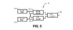
センサー6からのデータは、データ処理サブシステム9によって処理される。図5は、データ処理サブシステムのブロック図を示す(センサーと共に)。データ処理サブシステム9は、局所源検出器11と、P波検出器12と、P波トリガー13とを備える。P波検出器12は、センサー6からのデータを用いて、P波の存在を検出する。例えば、長期間にわたって平均化されたバックグラウンドノイズエネルギーを、短期間にわたって平均化された同じ推定と共に見ることによって、P波を検出することができる。短期間の値が長期間の値を超えていると、P波検出器は、衝撃波が検出されたという信号を送ることができる。局所源検出器11は、アレイの中心の5〜6ベースライン長以内(つまり、悪くても略500〜600メートル)等のサイトの近く(つまり、1km以内)に起源のある振動を、遠方で発生した振動から区別する。局所源は、地震ではなくて人間に由来するものであると仮定される。P波検出器12及び局所源検出器11の出力が、P波トリガーサブシステム13において比較されて、P波トリガーサブシステム13は、局所的起源である場合に、P波検出器12によって報告された全てのP波を拒絶する。図2に示されるように、地震起源のP波は通信サブシステム10に送られて、地震事象の震央及び深度を検出するために、他のサイトに送られるか、又は分析サブシステム35に直接送られる。 Data from
局所源検出器11のブロック図が、図6のブロック図に示されている。感知デバイス6からのデータは、サンプル毎に実時間で処理されて、二つのベクトル計算機15によって3次元方向ベクトルが計算される。三つよりも少ないチャネルが利用可能の場合、計算されるベクトルは、それに応じて少ない数の次元を有する。各ベクトルは、マグニチュード及び三つの方向余弦によって表される:
また、感知デバイスからのデータの相互相関が、相互相関器14によって計算される。好ましい実施形態では、Zチャネルが、初期地震運動に最も緊密に相関しているため(Pは主に垂直である)、相互相関用に用いられるが、入力チャネルのあらゆる組み合わせを相互相関させることができる。特定の遅延(D)に対する相互相関は以下のように表すことができる:
完全な相互相関が、−maxDelta…0…maxDeltaに対してDを反復適用することによって、計算される。ここで、maxDeltaは、サンプル周期の整数倍
maxDelta=N/FS
であり、ここで、Nは、センサーデータベクトルからのサンプル数である。Complete cross-correlation is calculated by iteratively applying D to -maxDelta ... 0 ... maxDelta. Here, maxDelta is an integer multiple of the sample period. MaxDelta = N / FS
Where N is the number of samples from the sensor data vector.
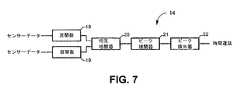
相互相関器14の処理ブロックのブロック図が、図7に示されている。感知デバイスからのデータ流は、(オプションの)窓関数19に送られる。窓関数19は、感知デバイスのデータの限定された時系列の使用を補償する。典型的な窓関数として、ハミング、ハン、ブラックマン、カイザーが挙げられる。窓を掛けられると、データ流は、相互相関関数20に送られる。効率的な処理のため、相互相関ルーチンは、ヘッド‐テイル関数として記述され、これは、周期毎の処理量を大幅に減らす。 A block diagram of the processing blocks of the cross-correlator 14 is shown in FIG. The data stream from the sensing device is sent to the (optional)
相互相関関数20の出力は、それ自体によって、局所源が存在するかどうかを求めるため、また、二つの感知デバイスのデータ流の間の時間遅延を求めるために用いられる。初めに、正規化された相互相関ピークが特定の値(20db等)よりも小さいと(10db未満等、例えば6db)、信号が非相関であると判定され、局所源であるとして拒絶される。 The output of the
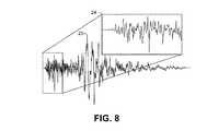
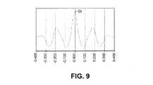
更に、相互相関関数20を用いて、二つの信号の間の時間遅延を検出することができる。何故ならば、時間遅延は、相互相関の出力においてピークとして表れるからである。垂直加速波形の例が図8に示されている。この波形におけるP波の部分は24で示されている一方、最初のS波のピークは23で示されている。相互相関の出力が図9に示されている。ピーク25が表れていて、5msの遅延を示している。 Furthermore, the
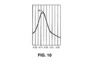
相互相関が図9に示されている。相互相関の値の間の補間によって、サブサンプルの時間差を得ることができる。これは、多項式又は他の方法を用いて、相互相関出力を補間することによって達成可能である。図10には、200Hzの相互相関が示されていて、そのピークは5msから10msの間にある。三次元スプライン補間は、7msのサブサンプル精度で時間遅延ピークを識別する。 Cross-correlation is shown in FIG. Subsample time differences can be obtained by interpolation between the values of the cross-correlations. This can be achieved by interpolating the cross-correlation output using a polynomial or other method. FIG. 10 shows a cross correlation of 200 Hz, whose peak is between 5 ms and 10 ms. Three-dimensional spline interpolation identifies time delay peaks with a sub-sample accuracy of 7 ms.
図7に戻ると、補間は、相互相関器の出力に対して21で行われ、ピークが22において求められる。 Returning to FIG. 7, interpolation is performed at 21 on the output of the cross-correlator and the peak is determined at 22.
図6に戻ると、ピークを用いて、二つの感知デバイスの間の到達時間差を測定する。想定される時間差の範囲は小さいので、センサーの離隔距離及び衝撃波の速度に基づいて、相互相関を、限定された数の遅延に対して計算することができる。200Hzのサンプルレートに対して、Dの値(計算された相互相関の時間遅延)をn=−2、−1、0、1、2として限定することができて、ここで、D=n/FSである。相互相関器に送られるデータ長は、より良い時間分解能を得るために、高次の補間に対してはより長くなければならない。Returning to FIG. 6, the peak is used to measure the arrival time difference between the two sensing devices. Since the expected time difference range is small, the cross-correlation can be calculated for a limited number of delays based on sensor separation and shock wave velocity. For a sample rate of 200 Hz, the value of D (the time delay of the calculated cross-correlation) can be limited as n = −2, −1, 0, 1, 2, where D = n / a FS. The data length sent to the cross-correlator must be longer for higher order interpolation to obtain better temporal resolution.
計算された時間遅延は、検出された信号が局所信号であるかどうかを決定するため、及び、更なる比較を可能にするためにベクトルデータをシフトさせるために用いられる。 The calculated time delay is used to determine whether the detected signal is a local signal and to shift the vector data to allow further comparison.
つまり、計算された時間遅延を用いて、感知デバイスの離隔距離及び局所的P波速度(公称6.2km/s)によって決定される狭い時間窓の中に、二つの感知デバイスのデータ流が存在しているかどうかを求めることができる。例えば、20mの離隔距離に対して、3.2ms以上の時間差を誤った事象であるとして記録することができる。このパラメータは、局所的P波速度のより良い推定に基づいて微調整される。 That is, with the calculated time delay, the data flow of the two sensing devices exists within a narrow time window determined by the separation distance of the sensing device and the local P-wave velocity (nominal 6.2 km / s) You can ask if you are. For example, a time difference of 3.2 ms or more can be recorded as an erroneous event for a separation distance of 20 m. This parameter is fine tuned based on a better estimate of the local P wave velocity.
更に、時間遅延を用いて、ベクトルをシフトするように可変時間遅延モジュール16を制御することができる。時間遅延モジュール16は、複数のタップを備えたシフトレジスタである。選択されたタップは、相互相関器からの時間遅延に対応する。そして、二つの時間遅延モジュールの出力を、時間に関して同期させて、比較を行うことができる。 In addition, the time delay can be used to control the variable
サブサンプル時間遅延に対して、隣接する方向ベクトルの間の線形補間が計算される:
更に図6を参照すると、時間が同期されると、ベクトルが17において比較される。この比較を用いて、二つのベクトル流の方向相関を求めることができる。振動の遠方の源(その距離は、感知デバイスの離隔距離と比較して長い)に対しては、方向ベクトルは平行である。これは、二つのベクトル流の方向余弦を比較することによって求められる。誤差の大きさが最大閾値(10度等)を超えると、その源は局所的であると判定される。
更に、この比較を用いて、二つのベクトル流の大きさの相関を求めることができる。二つの感知デバイスが同じ様に取り付けられていると、震源が同じ様に登録される。局所振動源は、他のものよりも一つの感知デバイス(最も近い)により大きな影響を与える傾向にある。特定のパーセンテージよりも大きい(例えば15%よりも大きい)大きさの差が、局所源を識別するのに用いることができる。 Furthermore, this comparison can be used to determine the correlation between the magnitudes of the two vector flows. If two sensing devices are installed in the same way, the epicenter will be registered in the same way. Local vibration sources tend to have a greater impact on one sensing device (closest) than others. A magnitude difference greater than a certain percentage (eg, greater than 15%) can be used to identify a local source.
局所性検出器18が局所事象を検出して、局所事象を拒絶することができる。上述の方法と一致して、局所性検出器の出力は、以下の場合に真(局所源を意味する)である:
vector_direction_error > directon_threshold OR
cross_correlation < xcorr_threshold OR
time_delay > time_threshold OR
|magn(sensor1)-magn(sensor2)| > magn_threshold OR
ratio(magn(sensor1) to magn(sensor2)) > magn_threshold OR
ratio(magn(sensor2) to magn(sensor1)) > magn_threshold OR
|time(P-wave1) - time(P-wave2)| > time_threshold OR
ratio(vertical to horizontal magnitudes) < P2S_thresholdA
vector_direction_error> directon_threshold OR
cross_correlation <xcorr_threshold OR
time_delay> time_threshold OR
| magn (sensor1) -magn (sensor2) |> magn_threshold OR
ratio (magn (sensor1) to magn (sensor2))> magn_threshold OR
ratio (magn (sensor2) to magn (sensor1))> magn_threshold OR
| time (P-wave1)-time (P-wave2) |> time_threshold OR
ratio (vertical to horizontal magnitudes) <P2S_threshold
上記のように、P波検出器がP波を検出すると、ノイズをフィルタリング除去するために信号に対する更なるテストを行うことができる。一実施形態では、P波は明確に識別された衝撃波であるので、ソフトウェアがP波に似た何かが存在することを独立的に決定した時点又は信号において“トリガー”を有する。トリガーのアルゴリズムは典型的に、短期間の平均振幅に対する長期間の平均振幅の比である。トリガーが各センサーにおいて検出された場合、時間遅延は特定の閾値(例えば、100mのベースライン長に対して略50ms以上)を超えてはならない。 As described above, once the P-wave detector detects the P-wave, further testing on the signal can be performed to filter out noise. In one embodiment, the P-wave is a clearly identified shock wave, so it has a “trigger” at the time or signal when the software independently determines that something similar to the P-wave exists. The trigger algorithm is typically the ratio of the long-term average amplitude to the short-term average amplitude. If a trigger is detected at each sensor, the time delay should not exceed a certain threshold (eg, about 50 ms or more for a 100 m baseline length).
また、P波として識別された信号に対して、その波を分析して、垂直対水平の比が正しいかどうかを求めることができる。つまり、P波運動は主に垂直(縦波)である一方、S波は主に水平(横波)であり、表面波は均一な混合比を有し得る(レイリー波、大抵の局所源が伝播する方法)。例えば、P2S閾値(P2S threshold)は2であり、つまり、垂直チャネルが水平チャネルの少なくとも2倍でないと、それは局所源である。 Also, the signal identified as a P wave can be analyzed to determine if the vertical to horizontal ratio is correct. That is, the P wave motion is mainly vertical (longitudinal wave), while the S wave is mainly horizontal (transverse wave), and the surface wave can have a uniform mixing ratio (Rayleigh wave, most local sources propagate) how to). For example, the P2S threshold is 2, ie, if the vertical channel is not at least twice the horizontal channel, it is a local source.
相互相関を用いた時間差の正確な測定は、高いサンプルレートによるものである。好ましい実施形態では、少なくとも100Hz(例えば少なくとも200Hz等)のサンプルレートが用いられる。局所条件が好まれる場合(誤りに近い、硬い岩盤の地質)、800Hzや1000Hz等のより高いサンプルレートを用いることができる。文化的ノイズは、地震振動よりも高い周波数を有する傾向にある。より高いサンプルレートによって、極めて積極的なアンチエイリアス入力フィルターを用いない限りはエイリアシングアーティファクトとして表れていたであろう文化的ノイズを簡単に検出することができる。より高い周波数サンプリングは、積極的なフィルターのコスト及び歪みを低下させる。 Accurate measurement of time differences using cross-correlation is due to high sample rates. In a preferred embodiment, a sample rate of at least 100 Hz (eg, at least 200 Hz) is used. If local conditions are preferred (hard rock geology close to errors), higher sample rates such as 800 Hz and 1000 Hz can be used. Cultural noise tends to have a higher frequency than earthquake vibration. The higher sample rate makes it easier to detect cultural noise that would have appeared as aliasing artifacts unless a very aggressive anti-aliasing input filter was used. Higher frequency sampling reduces the cost and distortion of aggressive filters.
ベクトルが局所起源の波を表し、P波が検出されない場合、振動は無視される。つまり、上述のように、垂直対水平の比と、時間遅延と、ベクトル相関との組み合わせによって識別される局所源波が、無視される。 If the vector represents a locally originating wave and no P wave is detected, the vibration is ignored. That is, as described above, the local source wave identified by the combination of the vertical to horizontal ratio, the time delay, and the vector correlation is ignored.
感知デバイスからの信号を、震源からの振動に対して十分に相関させる。相関が低い場合、信号は拒絶される。感知デバイスは、地盤振動に対する同様の応答を達成するために、同じ様に取り付けられなければならない。システムは、全ての地震事象からの振動を用いて、考えられる相関の程度を推定し、感知デバイスの応答の差を補償するようにその比較アルゴリズムを調整する。また、こうした方法は、誤判定の増大に寄与したであろう電気ノイズに対する優れた拒絶も提供する。 The signal from the sensing device is well correlated with the vibration from the epicenter. If the correlation is low, the signal is rejected. The sensing device must be mounted in the same way to achieve a similar response to ground vibration. The system uses vibrations from all seismic events to estimate the degree of possible correlation and adjusts its comparison algorithm to compensate for differences in sensing device responses. Such methods also provide excellent rejection of electrical noise that would have contributed to increased misjudgment.
説明される多くの方法は、P波速度等の局所パラメータの正確な推定によるものである。各事象がシステムによって検出及び測定されると、事象後分析において、こうしたパラメータを、他のサイトとの比較によって測定することができる。次に、パラメータが、P波の推定におけるシステムの精度を改善するように調整される。 Many of the methods described are by accurate estimation of local parameters such as P-wave velocity. As each event is detected and measured by the system, these parameters can be measured by comparison with other sites in a post-event analysis. The parameters are then adjusted to improve the accuracy of the system in P-wave estimation.
図2に戻ると、局所源からの振動を除去した後、センサーサブシステム2によって検出されたP波と、検出されたP波からのデータとが、通信サブシステム10を介して、EWS内の他のデバイス及び/又は分析サブシステム35に送信される。 Returning to FIG. 2, after removing the vibration from the local source, the P wave detected by the
〈分析サブシステム〉
図11のデータフロー図で、分析サブシステム35を詳述する。分析サブシステム35は次の三つの構成要素を有する:(1)P‐S関係(P‐to‐S relation)45、これは測定位置(つまり、センサーサブシステムの位置)における地震事象のP波の一つ以上のパラメータと、同じ位置で観測されたピーク地動との間の経験的関係を求めることを含む; (2)局所的震央処理要素46、これは、地震事象の震央を決定することを含む; (3)D‐S関係(D‐to‐S relation)49、これは、ピーク地動と震央からの距離との間の経験的関係を求めることを含む。<Analysis subsystem>
The
P‐S関係
上述のように、P‐S関係は、測定位置におけるP波の一つ以上のパラメータと同じ位置で観測されたピーク地動との間の関係を求めることを含む。この経験的関係は、地理的地域、深さ、震源メカニズム、必要に応じた他のパラメータによって分類された又は全体として調べられた膨大な数の歴史上の事象からの地震データに基づいている。P波パラメータは、時間領域又はスペクトル領域における振幅情報と、時間領域又はスペクトル領域のいずれかにおけるP波の他の特性を含む。ピーク地動は、ジャーク(jerk)、加速度、速度、変位、広帯域又は任意の対象周波数帯におけるスペクトル加速度として表される。経験的関係の関数形式は、線形、対数線形、又は他の形式であり得る。また、経験的関係は、源からの距離又は他の変数の関数であり得る。この関係をP‐S関係と呼ぶ。PS Relationship As described above, the PS relationship includes determining a relationship between one or more parameters of the P wave at the measurement location and the peak ground motion observed at the same location. This empirical relationship is based on seismic data from a vast number of historical events categorized or surveyed as a whole by geographical area, depth, source mechanism, and other parameters as needed. P-wave parameters include amplitude information in the time domain or spectral domain and other characteristics of the P wave in either the time domain or spectral domain. Peak ground motion is expressed as jerk, acceleration, velocity, displacement, wideband or spectral acceleration in any frequency band of interest. The functional form of the empirical relationship can be linear, log-linear, or other forms. Also, the empirical relationship can be a function of distance from the source or other variables. This relationship is called a PS relationship.
一実施形態では、対象地域における略100回の過去の地震からデータが収集される。地震は、マグニチュード単位において、ML3.0のものから、利用可能な最大の事象までのものである。質の高い地震記録が必要とされるため、分析においては、より最近の地震が好ましい。この好ましさには、マグニチュードスケールの上限での事象の珍しさによって限りがあり、必要に応じて、いくつかの最大事象は、大抵のより小さな事象よりもかなり古いものとなるが、これは許容可能である。何故ならば、大きな事象のより強力な地動は、小さな地震による地動よりも、ノイズの多い記録において目立つからである。数の多い小さなマグニチュードが重視され過ぎるのを防止するため、各マグニチュードにおける地震の数が略一定になるように、データセットが選択される。In one embodiment, data is collected from approximately 100 past earthquakes in the target area. Earthquake, at magnitude unit, is from those of the M L3.0, up to a maximum of events available. More recent earthquakes are preferred for analysis because high quality seismic records are required. This preference is limited by the rarity of events at the upper magnitude scale, and if necessary, some maximum events are much older than most smaller events, but this Is acceptable. This is because the stronger ground motion of a large event is more noticeable in noisy records than the ground motion of a small earthquake. The data set is selected so that the number of earthquakes in each magnitude is substantially constant in order to prevent too many small magnitudes from being emphasized too much.
各地震に対して、多数の地震記録が分析されて、震央からの距離、センサーのサイト分類、可能であれば地震の主成分ベクトルに対するステーションの方位角によって分けられる。この後者の分類は、信頼性のあるモーメントテンソルが計算されているMW4.0以上の地震に対してのみ可能である。各記録に対して、P波が、時間領域及び周波数領域において分析されて、S波又は表面波からのピーク地動が記録される。P波の分析結果とピーク地動との間の相関が計算されて、最良の相関、又は一組の最良の相関の組み合わせを用いて、経験的P‐S関係を発生させる。For each earthquake, a large number of seismic records are analyzed and separated by the distance from the epicenter, the sensor site classification, and possibly the azimuth of the station relative to the principal component vector of the earthquake. This latter classification is only possible for earthquakes of Mw 4.0 and above for which a reliable moment tensor has been calculated. For each record, the P wave is analyzed in the time domain and the frequency domain, and the peak ground motion from the S wave or surface wave is recorded. The correlation between the P-wave analysis results and the peak ground motion is calculated to generate an empirical PS relationship using the best correlation or a set of best correlation combinations.
図12は、経験的P‐S関係の一例を示し、ピーク地動加速度(PGA,peak ground acceleration)が、P波の或るパラメータに対数線形で関係している。グラフの各点は、歴史上の地震に対するこのP波パラメータとPGAの個々の観測点である。実線54は、これらのデータの最小二乗法の最良フィッティングであり、破線55は、このフィッティングに対する95%の信頼区間である。図12は、或る任意単位系において10に等しいこのP波のパラメータの仮想的な観測グラフの例である。最良フィッティングの線54及び95%信頼の線55と垂直線56との交点は、推定されたPGA57と、推定されたPGAに対する95%の信頼区間58とを与える。 FIG. 12 shows an example of an empirical PS relationship in which peak ground acceleration (PGA) is logarithmically related to a certain parameter of the P wave. Each point on the graph is an individual observation point of this P-wave parameter and PGA for historical earthquakes. The
どのP波のパラメータ又はパラメータの組み合わせを用いるのかの選択は、多様な要因に依存し、そうした要因として、震源メカニズム及び向きの変化に対するパラメータのロバスト性(つまり、横ずれ地震vs衝上断層vs通常の地震)、パラメータを用いて信頼性のある推定を行うことができる速度、対象震度範囲全体にわたるパラメータの利用可能性が挙げられる。最も基礎的なレベルでは、パラメータの選択は、どのパラメータがピーク地動と最も良く相関して、最も散乱が少ないかによって支配され、つまり、そうしたパラメータに対して、パラメータの値の不確実性は、地動の推定における最も小さな不確実性をもたらす。単一のパラメータはこうした全ての要求を同時に満たすことができないので、パラメータの組み合わせを、各パラメータの利点を最大にする重み付け法と共に用いることができる。例えば、振幅ベースのパラメータは、小さな地動に対してあまり散乱を示さないが、非常に大きな地動に対して飽和し得る。対照的に、周波数ベースのパラメータは、大きな地動に対する飽和の問題を有さないが、小さな地動に対する信号対ノイズ比の低さの問題を有し得る。この例における適切な方法では、推定された小さな地動に対して振幅ベースのパラメータに重みを置き、大きな推定に対して周波数ベースのパラメータに重みを置く。 The choice of which P-wave parameter or parameter combination to use depends on a variety of factors, including the robustness of the parameters to changes in source mechanism and orientation (ie, strike-slip earthquakes vs. thrust vs. normal Earthquake), the speed at which reliable estimation can be performed using parameters, and the availability of parameters over the entire seismic intensity range. At the most basic level, the choice of parameters is governed by which parameters are best correlated with peak ground motion and have the least scattering, that is, for such parameters, the uncertainty in the value of the parameter is Provides the least uncertainty in estimating ground motion. Since a single parameter cannot meet all these requirements simultaneously, a combination of parameters can be used with a weighting method that maximizes the benefits of each parameter. For example, amplitude-based parameters do not show much scattering for small ground motions but can be saturated for very large ground motions. In contrast, frequency-based parameters do not have saturation problems for large ground motions but may have low signal-to-noise ratio problems for small ground motions. A suitable method in this example places weights on amplitude-based parameters for small estimated ground motions and weights on frequency-based parameters for large estimates.
局所的震央処理
一部実施形態では、事象の震央が、単一のセンサーサブシステム2からのみのデータを用いて決定される。他の実施形態では、震央は、局所センサーシステム2からのデータと、(通信サブシステム10を介して)ネットワーク上で通信される他のステーションからのデータとの組み合わせを用いて、震央が決定される。Local epicenter processing In some embodiments, the epicenter of the event is determined using data from only a
システムによっては、単一のセンサーを用いて、震央を決定することができる。二つの水平軸を備えたセンサーの場合、両方のチャネルに対するP波の初動の振幅及び符号を、ベクトルの直交成分として組み合わせて、センサーから震央までの逆方位角を求めるのに用いることができる。一実施形態では、三軸センサーが用いられ、垂直チャネルに対するP波の初動の振幅及び符号が、入射P波の伏角を求めるのに追加的に用いられる。地域の1次元速度モデルを用いて、測定された伏角を震央距離に変換する。これは、周波数‐波数積分で実時間で行うことができる。一実施形態では、速度モデルを用いて、測定された伏角と震央距離との間の変換の事前ルックアップテーブルを発生させる。この方法は単独で使用可能であり(つまり、たった一つのセンサーを用いて震央を決定する)、又は、より正確な震央位置の識別のための他の方法を補強することができる。 In some systems, a single sensor can be used to determine the epicenter. In the case of a sensor with two horizontal axes, the amplitude and sign of the P wave initial motion for both channels can be combined as the orthogonal component of the vector and used to determine the reverse azimuth from the sensor to the epicenter. In one embodiment, a triaxial sensor is used and the amplitude and sign of the P wave initial motion relative to the vertical channel is additionally used to determine the dip angle of the incident P wave. Using the local one-dimensional velocity model, the measured dip is converted into epicenter distance. This can be done in real time with frequency-wavenumber integration. In one embodiment, a velocity model is used to generate a pre-lookup table for conversion between measured dip and epicenter distance. This method can be used alone (ie, using only one sensor to determine the epicenter) or can augment other methods for more accurate epicenter location identification.
一実施形態では、二つのセンサーが、既知のベースライン距離及び方位で同じサイトに配置され、初動の相対的な到達時間を用いて、以下の式で逆方位角を推定する:
図13は、遠方の源からの衝撃波を受信している或る距離d(23)によって離隔された二つのセンサー位置(S1及びS2)を示す。衝撃波は、光線経路21及び22に沿ってセンサーに到達する。図14は、上述の逆方位角を推定するのに用いられた式のグラフであり、図13の二つのセンサーにおける到達時間差に基づいた相互相関の角度分解能の精度を示す。このグラフは、100mで離隔された二つのセンサーに対するものである。 FIG. 13 shows two sensor positions (S1 and S2) separated by a certain distance d (23) receiving shock waves from a distant source. The shock wave reaches the sensor along the
一実施形態では、ボロノイセルが、EWS中の全ての動作サイトの周辺に構築されて、他のサイトが地動を検出していないとの情報を用いて、局所的なボロノイセル内に源を局在化させる。時間が経過しても、他のステーションがトリガーを報告しないと、震央が存在し得る地点が、トリガーにして第一のステーション付近に限定される。これは、ネットワークの正常状態と、地動を検出したかどうかについての周辺の全てのステーションの状態との一定の情報を必要とする。この情報は、一つ以上のステーションの状態が変化するたびに、通信サブシステム10によって非同期的に提供される。隣接するステーションが失敗した旨が報告されると、最初のステーションのボロノイセルが実時間で再計算されて、震央箇所の候補が、この変化を反映するようにアップデートされる。 In one embodiment, Voronoi cells are built around all operational sites in the EWS, and the source is localized within the local Voronoi cell using information that no other sites are detecting ground motion. Let Even if time passes, if no other station reports a trigger, the point where the epicenter may exist is limited to the vicinity of the first station as a trigger. This requires certain information about the normal state of the network and the state of all surrounding stations about whether or not ground motion has been detected. This information is provided asynchronously by the
一実施形態では、局所的震央処理要素46が、ボロノイセル及び隣接セル内の地質マップを局所的に保有している。これは、既知の断層線の位置やそれらの評価された地震災害等の固定データと、ボロノイセル内部での最近の全ての地震の位置等の可変データとを含む。こうしたデータを、方位角及び伏角のデータと組み合わせ、また、ボロノイセル自体と組み合わせて、震央位置候補の二次元(緯度/経度)確率分布を発生させる。一つ以上の隣接ステーションが事象を報告すると、この情報が局所的な震央の推定に組み込まれて、通信サブシステムを介して、残りのネットワークに伝えられる。 In one embodiment, the local
D‐S関係
震源からの距離に対するピーク地動の変動を記述する別の経験的関係が求められる。この経験的関係は、地理的地域、深さ、震源メカニズム、他のパラメータによって分類された(関係がこうしたパラメータに強く依存しているとわかった場合)膨大な数の歴史上の事象からの地震データに基づいている。こうしたパラメータに対する関係の変動がデータ内の散乱と比較して小さいと、事象が、均一なD‐S関係に到達したかが全体として調べられる。ピーク地動は、上述のP波に対する経験的関係に対する場合と同じ期間で表される。距離は、震源、震央、断層面、表面断層トレースからのものとして記載される。経験的関係は、あらゆる関数形式をとり得るが、ゼロの距離において明確に有限でなければならない。この関係がD‐S関係と呼ばれる。DS relationship Another empirical relationship is required to describe the variation of peak ground motion with distance from the epicenter. This empirical relationship was categorized by geographic region, depth, source mechanism, and other parameters (if the relationship was found to be strongly dependent on these parameters) earthquakes from a vast number of historical events Based on data. If the variation in the relationship to these parameters is small compared to the scatter in the data, it is examined as a whole whether the event has reached a uniform DS relationship. The peak ground motion is expressed in the same period as for the empirical relationship to the P wave described above. The distance is listed as from the epicenter, epicenter, fault plane, and surface fault trace. The empirical relationship can take any functional form, but must be clearly finite at zero distance. This relationship is called the DS relationship.
好ましい実施形態では、D‐S関係は以下の理論的関数形式に従う:
図15は、どのように図12の仮想観測を用いて、源からの全ての距離における地動を推定するのかをグラフで示す。図12において用いられた仮想ステーションが、源から3kmの距離にあるとすると、95%の信頼区間で図12から推定されたPGAは、図13のエラーバー69で白シンボルとしてプロットされる。D‐S関係は、推定されたPGA70に適合するようにスケーリングされて、95%の信頼曲線は、PGAの推定71の95%のエラーバーに適合するようにスケーリングされる。曲線が正確にスケーリングされると、他の距離における推定地動をグラフから読み取ることができる。この例では、ソース62から100kmにあるステーションのPGA63が、95%の信頼区間64で推定される。 FIG. 15 graphically shows how the ground motion at all distances from the source is estimated using the virtual observation of FIG. If the virtual station used in FIG. 12 is 3 km from the source, the PGA estimated from FIG. 12 with a 95% confidence interval is plotted as a white symbol in the
分析サブシステムを介したデータのストリーミング
図11に戻ると、データが、センサーサブシステム2から実時間でストリーミングされて、P‐S関係45及び局所的震央処理46に供給される。通信サブシステム10からの非同期データも、到達すると、局所的震央処理に供給される。P‐S関係45は、局所サイト47における差し迫ったピーク地動の確率分布を発生させて、局所的震央処理は、震央位置48の確率分布を生成する。震央位置がネットワークからのデータから既に推定されている場合、このデータは、通信サブシステム10から送られて、局所震央の結果を無効にして、不確実性を評価するために局所的結果と比較され得る。こうした確率は、通信サブシステム10に個別に報告されて、それらの情報が組み合わされてD‐S関係49に供給されて、差し迫ったピーク地動50の地域曲線を生成する。このデータも、通信サブシステム10に報告される。Streaming Data through the Analysis Subsystem Returning to FIG. 11, data is streamed in real time from the
P‐S関係及び震央の推定により推定された不確実性は、標準的な誤差伝播法(本願では詳述しない)を用いてD‐S関係から地域曲線に伝播される。地域曲線における最終的な全不確実性は、通信サブシステム10に送られる。 Uncertainty estimated by the PS relationship and epicenter estimation is propagated from the DS relationship to the regional curve using standard error propagation methods (not detailed in this application). The final total uncertainty in the regional curve is sent to the
〈通信サブシステム〉
図2に戻ると、通信サブシステム10は、センサーサブシステム2同士の通信と、センサーサブシステム2と分析サブシステム35との間の通信を提供することに関与する。<Communication subsystem>
Returning to FIG. 2, the
従って、局所的及び地域的地動並びに震央位置の推定結果が、通信サブシステム10に送られて、通信サブシステム10は、必要に応じて、局所EWSに、ピアサイトの地域ネットワークに、又は、地域サイトに対する再分配用のマスターデータセンサーに推定結果を分配する。また、通信サブシステム10は、他のピアサイトから、又はマスターデータセンターからデータを受信して、必要に応じて、局所的分析に組み込むために分析サブシステム35にデータを送る。 Accordingly, local and regional ground motion and epicenter location estimation results are sent to the
局所的及び地域的地動の推定の不確実性並びに震央位置の不確実性は、分析サブシステム35内部において連続的に記録されて伝播される。不確実性は、センサーサブシステム2及び通信サブシステム10からの入力データの質及び一貫性と、P波と地動45との間の所定の関係の固有の不確実性との組み合わせから導出される。不確実性は分析サブシステム35から通信サブシステム10に送られて、ネットワーク上に送信するための一組のパラメータ値にエンコードされる。 Local and regional ground motion estimation uncertainties and epicenter location uncertainties are continuously recorded and propagated within the
通信サブシステム10は、データを送受信するためのシステム(イーサネット(登録商標)、ワイヤレス等)、通信が行われるデバイスを認証するためのモジュール、干渉から通信を保護するためのシステム(暗号化等)、全ての通信が無事に完了したことを保証するためのシステム(プロトコル)、及び/又は、通信されたデータのエラーを検出するためのシステム(ECC)を含むことができる。 The
推定震度の確率的表現
通信サブシステム10は、数量不定のデータ点を備えたテーブル又は区分線形関数として、震央及び地動の確率分布を通信するように構成される。区分線形近似として考えられる一実施形態は、単純に、所望の分解能の確率関数に落として、つまり、ラスター形式の確率として、各点における確率を伝えることである。これは、計算は単純であるが、送信が高くつく。好ましい実施形態では、確率分布関数をガウス分布として近似して、以下の二つのパラメータ値(“マトリクス”)を用いてエンコードする:一つは、予測値(ev)を表し、一つは、分布の偏差(dev)を表す。好ましい実施形態では、パラメータevは、平均分布をエンコードし、パラメータdevは標準偏差をエンコードする。他の表現も可能であり、devが、分散、半値全幅、95%信頼区間、他の偏差の尺度をエンコードすることができる。好ましい実施形態では、差し迫ったピーク地動の確率分布は、以下の関数で近似され、
他の確率関数も可能である。evが位置をエンコードしてdevがスケールをエンコードするコーシー分布は以下の形式に従う
同じエンコードのラプラス分布は以下の形式に従う
非連続分布関数も適用可能である。例えば、考えられる最大及び最少の地動が既知であり(mn及びmx)、その区間に対する震度の傾向が等しいと判断される(又は、より現実的な確率分布を発生されるには十分ではないと分かった)場合、均一分布関数が適用される:
縮退している場合には、ただ一つの推定ピーク地動のみがわかっていて他の不確実性が利用可能ではないと、確率はディラックのデルタ関数になる:
震央位置をエンコードする場合、同じ確率関数が二次元に拡張される。ガウス分布として実施する場合、これは、以下の四つの行列をもたらす;ev緯度、ev経度、dev緯度、ev経度。これは、多変数ガウス分布の最も一般的な場合ではない。一般化形式では、devを共分散行列として表す必要がある。この場合、devの成分が、dev緯度,経度、dev経度,経度、dev経度,緯度、dev緯度,緯度とラベル付けされる。この形式は、主軸に沿った偏差と、回転角として(dev1、dev2、θ)より効率的に表される。この形式が好ましい実施形態である。When encoding epicenter location, the same probability function is extended to two dimensions. When implemented as a Gaussian distribution, this results in the following four matrices; evlatitude , evlongitude , devlatitude , evlongitude . This is not the most common case of a multivariable Gaussian distribution. In the generalized form, dev must be expressed as a covariance matrix. In this case, the components of dev are labeled as devlatitude, longitude , devlongitude, longitude , devlongitude, latitude , devlatitude, latitude . This form is more efficiently represented as (dev1 , dev2 , θ) as deviations along the main axis and rotation angles. This format is the preferred embodiment.
通信
通信サブシステム10は、分析サブシステムと図1に示される広域EWSとの間の非同期通信を促進する。従って、通信サブシステム10は、地震警報を解釈して適切な応答に変換する少なくとも一つのデバイスを含む。一実施形態では、広域EWSは、インターネットを介してデータを受信して対象地域内に地理的に分布した同一のシステムに分配する地域データセンサーも含む。広域EWSは、地域データセンターを有さずに、同一システムのピアツーピアネットワークの形式をとってもよい。Communication The
局所システムと地域ネットワークと応答デバイスとの間の通信プロトコルを実現するのに加えて、通信サブシステム10は、ネットワーク上での効率的な通信のために、地動及び震央位置の推定及びそれら各々の不確実性をエンコードするのに関与している。 In addition to implementing the communication protocol between the local system, the regional network, and the response device, the
一実施形態では、計算された震度が特定の閾レベルに達した場合に、警報が発せられる。 In one embodiment, an alarm is triggered when the calculated seismic intensity reaches a certain threshold level.
1 断層
2 センサーサブシステム
3 震央
4 P波
10 通信サブシステム
35 分析サブシステム1
Claims (90)
Translated fromJapanese測定位置において少なくとも一つのセンサーを用いて地震事象のP波を検出するステップと、
前記地震事象のマグニチュードを決定せずに、検出されたP波の少なくとも一つのパラメータを用いて前記測定位置における推定ピーク震度を決定するステップと、
前記地震事象の震央を決定するステップと、
決定された推定ピーク震度と前記震央からの特定位置の距離とを用いて、特定位置における前記地震事象の震度を推定するステップとを備えた方法。A method for detecting an earthquake event,
Detecting a P-wave of an earthquake event using at least one sensor at a measurement location;
Determining an estimated peak seismic intensity at the measurement location using at least one parameter of a detected P-wave without determining the magnitude of the seismic event;
Determining an epicenter of the seismic event;
Estimating the seismic intensity of the seismic event at a specific location using the determined estimated peak seismic intensity and the distance of the specific location from the epicenter.
地震事象のP波を検出するように構成された少なくとも二つのセンサーと、
制御装置とを備え、前記制御装置が、
前記地震事象のマグニチュードを決定せずに、検出されたP波の少なくとも一つのパラメータを用いて推定ピーク震度を決定し、
前記地震事象の震央を決定して、
決定された推定ピーク震度と前記震央からの特定位置の距離とを用いて、特定位置における前記地震事象の震度を推定するように構成されている、システム。A system for detecting seismic events,
At least two sensors configured to detect P waves of seismic events;
A control device, the control device,
Determining the estimated peak seismic intensity using at least one parameter of the detected P wave without determining the magnitude of the seismic event;
Determine the epicenter of the earthquake event,
A system configured to estimate the seismic intensity of the seismic event at a specific location using the determined estimated peak seismic intensity and the distance of the specific location from the epicenter.
測定位置において少なくとも二つのセンサーを用いて地震事象のP波を検出するステップと、
検出されたP波の少なくとも一つのパラメータを用いて前記測定位置における推定ピーク震度を決定するステップと、
前記測定位置において前記少なくとも二つのセンサーのみを用いて、前記地震事象の震央を決定するステップと、
決定された推定ピーク震度と前記震央からの特定位置の距離とを用いて、特定位置における前記地震事象の震度を推定するステップとを備え、
前記少なくとも二つのセンサーが500m以下で離れている、方法。A method for detecting an earthquake event,
Detecting a P wave of an earthquake event using at least two sensors at a measurement location;
Determining an estimated peak seismic intensity at the measurement location using at least one parameter of the detected P-wave;
Determining the epicenter of the seismic event using only the at least two sensors at the measurement location;
Using the determined estimated peak seismic intensity and the distance of the specific position from the epicenter to estimate the seismic intensity of the earthquake event at the specific position,
The method wherein the at least two sensors are separated by 500 m or less.
地震事象のP波を検出するように構成された少なくとも二つのセンサーと、
制御装置とを備え、
前記少なくとも二つのセンサーが500m以下で離れていて、
前記制御装置が、
検出されたP波の少なくとも一つのパラメータを用いて推定ピーク震度を決定し、
測定位置において前記少なくとも二つのセンサーのみを用いて前記地震事象の震央を決定し、
決定された推定ピーク震度と前記震央からの特定位置の距離とを用いて、特定位置における地震事象の震度を推定するように構成されている、システム。A system for detecting seismic events,
At least two sensors configured to detect P waves of seismic events;
A control device,
The at least two sensors are separated by 500 m or less,
The control device is
Determining an estimated peak seismic intensity using at least one parameter of the detected P-wave;
Determining the epicenter of the seismic event using only the at least two sensors at a measurement location;
A system configured to estimate a seismic intensity of a seismic event at a specific location using the determined estimated peak seismic intensity and the distance of the specific location from the epicenter.
第一の位置にある第一のセンサーから第一の地盤振動信号を取得するステップと、
前記第一の位置から500m以内の第二の位置にある第二のセンサーから第二の地盤振動信号を取得するステップと、
前記第一の信号及び前記第二の信号を相関させるステップと、
前記第一の信号及び前記第二の信号の相関が設定された閾値に合致する場合にのみ、前記第一の信号又は前記第二の信号の少なくとも一つのパラメータを用いて、地震事象の震度を推定するステップとを備えた方法。A method for detecting a P wave of an earthquake event,
Obtaining a first ground vibration signal from a first sensor at a first position;
Obtaining a second ground vibration signal from a second sensor at a second position within 500 m from the first position;
Correlating the first signal and the second signal;
Only when the correlation between the first signal and the second signal matches a set threshold, the seismic intensity of the seismic event is calculated using at least one parameter of the first signal or the second signal. And a step of estimating.
第一の位置にあり、第一の地盤振動信号を取得するように構成された第一のセンサーと、
前記第一の位置から500m以内の第二の位置にあり、第二の地盤振動信号を取得するように構成された第二のセンサーと、
制御装置とを備え、前記制御装置が、
前記第一の信号及び前記第二の信号を相関させて、
前記第一の信号及び前記第二の信号が設定された閾値に合致する場合にのみ、前記第一の信号又は前記第二の信号の少なくとも一つのパラメータを用いて、地震事象の震度を推定するように構成されている、システム。A system for detecting seismic events,
A first sensor in a first position and configured to obtain a first ground vibration signal;
A second sensor at a second position within 500 m from the first position and configured to obtain a second ground vibration signal;
A control device, the control device,
Correlating the first signal and the second signal;
The seismic intensity of the seismic event is estimated using at least one parameter of the first signal or the second signal only when the first signal and the second signal meet a set threshold. Configured as a system.
Applications Claiming Priority (6)
| Application Number | Priority Date | Filing Date | Title |
|---|---|---|---|
| US201061424175P | 2010-12-17 | 2010-12-17 | |
| US201061424193P | 2010-12-17 | 2010-12-17 | |
| US201061424165P | 2010-12-17 | 2010-12-17 | |
| US61/424,193 | 2010-12-17 | ||
| US61/424,175 | 2010-12-17 | ||
| US61/424,165 | 2010-12-17 |
Related Parent Applications (1)
| Application Number | Title | Priority Date | Filing Date |
|---|---|---|---|
| JP2013544867ADivisionJP2014503818A (en) | 2010-12-17 | 2011-12-19 | Earthquake warning system |
Publications (1)
| Publication Number | Publication Date |
|---|---|
| JP2016194530Atrue JP2016194530A (en) | 2016-11-17 |
Family
ID=46245413
Family Applications (2)
| Application Number | Title | Priority Date | Filing Date |
|---|---|---|---|
| JP2013544867APendingJP2014503818A (en) | 2010-12-17 | 2011-12-19 | Earthquake warning system |
| JP2016157382APendingJP2016194530A (en) | 2010-12-17 | 2016-08-10 | Earthquake warning system |
Family Applications Before (1)
| Application Number | Title | Priority Date | Filing Date |
|---|---|---|---|
| JP2013544867APendingJP2014503818A (en) | 2010-12-17 | 2011-12-19 | Earthquake warning system |
Country Status (13)
| Country | Link |
|---|---|
| US (1) | US9372272B2 (en) |
| EP (1) | EP2652529A4 (en) |
| JP (2) | JP2014503818A (en) |
| CN (1) | CN103460073A (en) |
| AU (1) | AU2011343454B2 (en) |
| CA (1) | CA2821718A1 (en) |
| CL (1) | CL2013001751A1 (en) |
| MX (1) | MX2013006837A (en) |
| NZ (2) | NZ612013A (en) |
| PE (1) | PE20140367A1 (en) |
| PH (1) | PH12013501251A1 (en) |
| TW (1) | TWI557695B (en) |
| WO (1) | WO2012083294A2 (en) |
Cited By (4)
| Publication number | Priority date | Publication date | Assignee | Title |
|---|---|---|---|---|
| JP2018087799A (en)* | 2016-11-29 | 2018-06-07 | 財團法人國家實驗研究院National Applied Research Laboratories | Site type earthquake early warning system for automatically calibrating ground property, and related method thereof |
| JP2018197679A (en)* | 2017-05-23 | 2018-12-13 | 株式会社ミエルカ防災 | Earthquake warning system |
| KR20220067588A (en)* | 2020-11-16 | 2022-05-25 | 주식회사 동일아이씨티 | method for real time discriminating seismic motion |
| JP7109120B1 (en) | 2021-12-06 | 2022-07-29 | 株式会社ミエルカ防災 | A detection device for detecting seismic motion and a prediction device for predicting the intensity of seismic motion based on the detection results |
Families Citing this family (49)
| Publication number | Priority date | Publication date | Assignee | Title |
|---|---|---|---|---|
| CA2821718A1 (en)* | 2010-12-17 | 2012-06-21 | Seismic Warning Systems, Inc. | Earthquake warning system |
| PE20141715A1 (en) | 2011-02-26 | 2014-11-13 | Seismic Warning Systems Inc | CUSTOMIZABLE POLICY ENGINE |
| US9465121B2 (en)* | 2011-08-19 | 2016-10-11 | National Applied Research Laboratories | System and method for on-site instant seismic analysis |
| CN103033844A (en)* | 2012-12-12 | 2013-04-10 | 中国地震局地震研究所 | Single station earthquake P wave detection warning device |
| US9558644B2 (en)* | 2013-03-15 | 2017-01-31 | Vivint, Inc. | Security system with earthquake detection |
| JP6124253B2 (en)* | 2013-03-18 | 2017-05-10 | 国立研究開発法人防災科学技術研究所 | Seismic motion measuring apparatus, seismic motion measuring system and seismometer characteristic determining method using the same |
| EP2902809B1 (en)* | 2014-01-31 | 2022-04-13 | Draka Elevator Products, Inc. | Seismic-detection sensor device for vertical transportation equipment |
| TWI636276B (en)* | 2014-05-16 | 2018-09-21 | 財團法人國家實驗研究院 | Method of determining earthquake with artificial intelligence and earthquake detecting system |
| JP6347480B2 (en)* | 2014-05-27 | 2018-06-27 | 独立行政法人石油天然ガス・金属鉱物資源機構 | Vibration detection system, signal processing apparatus, and signal processing method |
| JP6401003B2 (en)* | 2014-10-02 | 2018-10-03 | 公益財団法人鉄道総合技術研究所 | Early warning method for short-distance earthquakes using seismic waves at a single observation point |
| US20160209532A1 (en)* | 2014-11-17 | 2016-07-21 | Board Of Regents, The University Of Texas System | Applied interpolation techniques |
| TWI541770B (en)* | 2015-01-08 | 2016-07-11 | 財團法人國家實驗研究院 | Earthquake alarm broadcast equipment and method thereof |
| CN104964666B (en)* | 2015-06-01 | 2017-07-14 | 山东鼎成卫星导航定位技术有限公司 | A kind of GNSS deformation monitoring methods and system based on virtual acceleration |
| WO2017083556A1 (en)* | 2015-11-11 | 2017-05-18 | The Regents Of The University Of California | Myshake: smartphone-based earthquake early warning system |
| US10740684B1 (en)* | 2015-12-09 | 2020-08-11 | One Concern, Inc. | Method and system to predict the extent of structural damage |
| US10915829B1 (en) | 2015-12-09 | 2021-02-09 | One Concern, Inc. | Data model update for structural-damage predictor after an earthquake |
| US10909647B2 (en) | 2015-12-09 | 2021-02-02 | One Concern, Inc. | Damage data propagation in predictor of structural damage |
| US11004001B1 (en) | 2015-12-09 | 2021-05-11 | One Concern, Inc. | Analysis of structural-damage predictions caused by an earthquake to identify areas with high damage levels |
| KR101697227B1 (en)* | 2016-05-23 | 2017-01-17 | 한국지질자원연구원 | Method for determining epicenter location in order to prevent false alarms of an earthquake early warning system using forced association of adjacent observation station information |
| CA3027717C (en) | 2016-10-19 | 2019-05-28 | Weir-Jones Engineering Consultants Ltd. | Systems and methods for early warning of seismic events |
| CN106982258B (en)* | 2017-04-06 | 2018-02-23 | 厦门帝嘉科技有限公司 | Earthquake early-warning system |
| TWI620154B (en)* | 2017-04-11 | 2018-04-01 | 楊偉智 | User equipment, earthquake alert server and earthquake alert method thereof |
| CN107193038A (en)* | 2017-05-25 | 2017-09-22 | 王建衡 | Across fracture belt Horizontal Deformation seismic monitoring device |
| WO2019130181A1 (en)* | 2017-12-26 | 2019-07-04 | Ramot At Tel-Aviv University Ltd. | Real-time array-based seismic source location |
| US11119453B2 (en)* | 2018-03-09 | 2021-09-14 | Nishil Thomas Koshy | System and method for remote non-intrusive monitoring of assets and entities |
| CN108490481A (en)* | 2018-05-18 | 2018-09-04 | 惠安县金建达电子科技有限公司 | A kind of underground longitude and latitude monitoring device for geology field |
| CL2018002014A1 (en)* | 2018-07-24 | 2018-09-14 | Xancura Spa | Alert system and method of estimated arrival time and expected intensity in a given area, product of a seismic movement. |
| IT201800011084A1 (en)* | 2018-12-14 | 2019-03-14 | Ignazio Congiu | SYSTEM FOR REPORTING THE IMMINENT OCCURRENCE OF SEISMIC EVENTS |
| US10520103B1 (en) | 2019-01-04 | 2019-12-31 | Mohammad Taghi Fatehi | Intelligent retrofit seismic wave detector and valve shutoff device |
| US10876277B1 (en) | 2019-01-04 | 2020-12-29 | Mohammad Taghi Fatehi | Automatic seismic wave detector and valve controller |
| WO2021033501A1 (en)* | 2019-08-20 | 2021-02-25 | 日本電気株式会社 | Seismic observation device, seismic observation method, and recording medium on which seismic observation program is recorded |
| CN110688773A (en)* | 2019-10-14 | 2020-01-14 | 中国电建集团成都勘测设计研究院有限公司 | System and method for quickly positioning drainage basin blockage |
| CN115867829B (en)* | 2020-07-13 | 2025-07-22 | 通用电气可再生能源西班牙有限公司 | System comprising a wind turbine and method for operating the system |
| JP7527255B2 (en)* | 2020-12-02 | 2024-08-02 | 大成建設株式会社 | How to synchronize time between multiple sensors |
| DE102020215422A1 (en) | 2020-12-07 | 2022-06-09 | Robert Bosch Gesellschaft mit beschränkter Haftung | Method and control unit for operating an early warning system for hazards, as well as a vehicle and early warning system |
| CN113406699B (en)* | 2021-07-13 | 2022-04-29 | 武汉大学 | A method and system for rapid determination of seismic source based on a single rectangular model |
| CN114217347B (en)* | 2021-11-08 | 2025-07-04 | 天地科技股份有限公司 | Microseismic source positioning method, device and computer equipment based on Thiessen polygons |
| CN114509811B (en)* | 2022-01-28 | 2022-12-02 | 中国地震局地球物理研究所 | Single station rear azimuth estimation method and device based on deep learning |
| CN114721049B (en)* | 2022-03-11 | 2024-04-09 | 新疆维吾尔自治区地震局 | Virtual seismic station azimuth participating off-grid seismic positioning method |
| TWI812132B (en)* | 2022-03-30 | 2023-08-11 | 財團法人國家實驗研究院 | High-power seismic wave early warning method and system, and computer-readable recording medium |
| CN114966833B (en)* | 2022-04-13 | 2025-01-03 | 应急管理部国家自然灾害防治研究院 | Synchronous magnitude estimation method and device for extracting P wave arrival time in earthquake early warning system |
| CN114993461B (en)* | 2022-08-08 | 2022-11-04 | 成都久和建设设备有限责任公司 | System and method for detecting vibration of motor of tower crane mechanism |
| TWI849508B (en)* | 2022-09-16 | 2024-07-21 | 衛波科技股份有限公司 | Method of determining earthquake by intersection of time series and energy of a plurality of seismographs |
| TWI880165B (en)* | 2023-01-19 | 2025-04-11 | 衛波科技股份有限公司 | On-site earthquake early warning system and method |
| CN116299704B (en)* | 2023-03-20 | 2025-06-24 | 四川西南交大铁路发展股份有限公司 | Earthquake single-unit positioning correction method, system, storage medium and terminal |
| FR3157564A1 (en)* | 2023-12-21 | 2025-06-27 | Sagemcom Energy & Telecom Sas | Method and device for detecting earthquakes |
| CN117765689B (en)* | 2024-02-22 | 2024-05-10 | 山东光合云谷大数据有限公司 | Geological disaster monitoring and early warning system |
| CN118379862B (en)* | 2024-06-24 | 2024-08-20 | 济宁矿业集团有限公司霄云煤矿 | Risk early warning method based on coal mine accident disaster feature matching |
| CN118540157B (en)* | 2024-07-23 | 2024-11-22 | 厦门帝嘉科技股份有限公司 | A system capable of encrypting earthquake early warning information |
Citations (18)
| Publication number | Priority date | Publication date | Assignee | Title |
|---|---|---|---|---|
| JPS5247341B1 (en)* | 1970-12-29 | 1977-12-01 | ||
| JPS5714775A (en)* | 1980-07-01 | 1982-01-26 | Japanese National Railways<Jnr> | Early detection alarm system for earthquake |
| JPS608468B2 (en)* | 1980-09-25 | 1985-03-02 | 日本国有鉄道 | Earthquake early detection warning system |
| JPH02228584A (en)* | 1989-03-02 | 1990-09-11 | Nippon Mining Co Ltd | Detecting system of moving object and apparatus therefor |
| US5101195A (en)* | 1988-12-15 | 1992-03-31 | Quakeawake Corporation | Discriminating earthquake detector |
| JPH11118768A (en)* | 1997-10-13 | 1999-04-30 | Nkk Corp | Method and apparatus for detecting paint film damage position of buried steel pipe |
| JP2002365320A (en)* | 2001-06-12 | 2002-12-18 | Etani Denki Kk | Measurement method of transmission characteristics for acoustic and electrical/electronic transmission line |
| JP2005195366A (en)* | 2003-12-26 | 2005-07-21 | Matsushita Electric Ind Co Ltd | Earthquake information transceiver system |
| JP2005537484A (en)* | 2002-08-30 | 2005-12-08 | サイズミック・ウォーニング・システムズ・インコーポレーテッド | Sensor device and method for detecting a P wave generated by an earthquake and generating a response control signal |
| JP2006112922A (en)* | 2004-10-14 | 2006-04-27 | Toshiba Corp | Earthquake early warning device and earthquake early warning method |
| JP2006284200A (en)* | 2005-03-31 | 2006-10-19 | Railway Technical Res Inst | Early earthquake detection system by microarray |
| JP2007198813A (en)* | 2006-01-25 | 2007-08-09 | Matsushita Electric Works Ltd | Seismograph |
| JP2008102691A (en)* | 2006-10-18 | 2008-05-01 | Sangyo Kiden:Kk | Multiple dwelling house intercom linkage system and multiple dwelling house intercom system |
| JP2008522140A (en)* | 2004-11-25 | 2008-06-26 | ラヒェニト,ハインツ | Earthquake warning system |
| JP2009174979A (en)* | 2008-01-24 | 2009-08-06 | Oki Semiconductor Co Ltd | Earthquake disaster prevention system |
| JP2010230407A (en)* | 2009-03-26 | 2010-10-14 | Taisei Corp | Earthquake motion prediction system |
| JP2010276536A (en)* | 2009-05-29 | 2010-12-09 | A2 Corp | Earthquake judgment system and earthquake analysis method |
| JP2014503818A (en)* | 2010-12-17 | 2014-02-13 | サイズミック・ワーニング・システムズ・インコーポレイテッド | Earthquake warning system |
Family Cites Families (42)
| Publication number | Priority date | Publication date | Assignee | Title |
|---|---|---|---|---|
| US3707699A (en)* | 1970-08-07 | 1972-12-26 | Del Mar Eng Lab | Remote scoring system for bombing or rocket range |
| US4516206A (en)* | 1982-10-21 | 1985-05-07 | Mcevilly Thomas V | Post-processing of seismic parameter data based on valid seismic event determination |
| USH374H (en)* | 1987-02-09 | 1987-11-03 | The United States Of America As Represented By The Secretary Of The Army | Optimum multiple target detection and resolution |
| JP2636656B2 (en) | 1993-01-26 | 1997-07-30 | 鹿島建設株式会社 | Vibration control or seismic isolation effect display |
| US5771170A (en)* | 1994-02-14 | 1998-06-23 | Atlantic Richfield Company | System and program for locating seismic events during earth fracture propagation |
| US5724241A (en)* | 1996-01-11 | 1998-03-03 | Western Atlas International, Inc. | Distributed seismic data-gathering system |
| US5983162A (en)* | 1996-08-12 | 1999-11-09 | The United States Of America As Represented By The Administrator Of The National Aeronautics And Space Administration | Computer implemented empirical mode decomposition method, apparatus and article of manufacture |
| US5910763A (en) | 1997-02-18 | 1999-06-08 | Flanagan; John | Area warning system for earthquakes and other natural disasters |
| US6208247B1 (en) | 1998-08-18 | 2001-03-27 | Rockwell Science Center, Llc | Wireless integrated sensor network using multiple relayed communications |
| GB9906995D0 (en)* | 1998-09-16 | 1999-05-19 | Geco Prakla Uk Ltd | Seismic detection apparatus and related method |
| JP2000121743A (en)* | 1998-10-14 | 2000-04-28 | Osaka Gas Co Ltd | Evaluating method for seismic shake distribution |
| US6816878B1 (en) | 2000-02-11 | 2004-11-09 | Steven L. Zimmers | Alert notification system |
| US6654689B1 (en) | 2000-11-06 | 2003-11-25 | Weather Central, Inc. | System and method for providing personalized storm warnings |
| JP4253435B2 (en) | 2000-11-30 | 2009-04-15 | 東京電力株式会社 | Method and apparatus for estimating seismic intensity |
| JP3463677B2 (en)* | 2001-10-04 | 2003-11-05 | 独立行政法人防災科学技術研究所 | How to determine the epicenter |
| US6731220B2 (en) | 2002-04-02 | 2004-05-04 | Industrial Technology Research Institute | Strong shaking judgment device and method |
| US7196634B2 (en)* | 2002-04-10 | 2007-03-27 | Science Horizons, Inc. | Systems for predicting earthquakes and methods of employing such systems |
| KR200324722Y1 (en) | 2003-04-16 | 2003-08-27 | 장병화 | Automatic Broadcasting System for Disaster Warning and Living Information with Automatic Weather Observation Apparatus |
| US20050027571A1 (en)* | 2003-07-30 | 2005-02-03 | International Business Machines Corporation | Method and apparatus for risk assessment for a disaster recovery process |
| CN1701243A (en) | 2003-08-27 | 2005-11-23 | 恩益禧慕百霖株式会社 | Earthquake prediction method and system thereof |
| JP4160033B2 (en)* | 2004-09-09 | 2008-10-01 | 財団法人鉄道総合技術研究所 | Early measurement seismic intensity prediction method and apparatus therefor |
| US7463162B1 (en) | 2005-03-21 | 2008-12-09 | Jamshid Hosseini | Earthquake alarm system |
| US7353114B1 (en) | 2005-06-27 | 2008-04-01 | Google Inc. | Markup language for an interactive geographic information system |
| US7280920B1 (en)* | 2005-06-29 | 2007-10-09 | Whiteside Lowell S | Method and apparatus for forecasting earthquakes and making informed risk management decisions |
| US20070104028A1 (en)* | 2005-11-04 | 2007-05-10 | Dirk-Jan Van Manen | Construction and removal of scattered ground roll using interferometric methods |
| JP4758759B2 (en)* | 2005-12-27 | 2011-08-31 | 株式会社ミツトヨ | Earthquake disaster prevention system |
| JP4980645B2 (en) | 2006-05-01 | 2012-07-18 | 東海旅客鉄道株式会社 | Direct earthquake type seismometer, seismometer system, direct earthquake earthquake warning method and program |
| EP1970855B1 (en) | 2007-03-13 | 2019-03-13 | Swiss Reinsurance Company Ltd. | Electronic control device and method for controlling cellular alarm systems |
| TWI335003B (en) | 2007-05-18 | 2010-12-21 | Nat Applied Res Laboratories | Earthquake warning system and method |
| JP5009076B2 (en)* | 2007-07-30 | 2012-08-22 | 鹿島建設株式会社 | Earthquake early warning system |
| JP4385233B2 (en) | 2007-07-31 | 2009-12-16 | 日本電気株式会社 | Earthquake prediction information notification server, earthquake prediction information notification system, earthquake prediction information notification method and program |
| WO2009037895A1 (en)* | 2007-09-21 | 2009-03-26 | Sanyo Electric Co., Ltd. | Communication device |
| US20090295587A1 (en) | 2008-03-02 | 2009-12-03 | Gorman Jr Thomas Leo | Severe weather, environmental and mass notification warning system and method |
| CN101577036B (en) | 2008-07-10 | 2010-11-17 | 王振宇 | Earthquake alarm |
| CN101354757B (en) | 2008-09-08 | 2010-08-18 | 中国科学院地理科学与资源研究所 | Method for predicting dynamic risk and vulnerability under fine dimension |
| JP2010091480A (en) | 2008-10-09 | 2010-04-22 | Ohbayashi Corp | Long-period ground motion detector and long-period ground motion detecting method |
| US20100169021A1 (en) | 2008-12-31 | 2010-07-01 | Nokia Corporation | Earthquake detection apparatus, system, and method |
| US8125852B2 (en) | 2009-05-25 | 2012-02-28 | Schlumberger Technology Corporation | Methods and systems for seismic signal detection |
| CN101567124B (en) | 2009-06-04 | 2012-05-02 | 山东省科学院海洋仪器仪表研究所 | A marine disaster early warning method |
| CN101630011A (en) | 2009-08-10 | 2010-01-20 | 南阳师范学院 | Earthquake monitoring and alarming device based on virtual instrument |
| CN101996470A (en) | 2009-08-11 | 2011-03-30 | 融智信科技发展(北京)有限公司 | Wireless earthquake warning based on MEMS accelerometer |
| US8519860B2 (en) | 2010-04-09 | 2013-08-27 | Weather Decision Technologies | Multimedia alerting |
- 2011
- 2011-12-19CACA2821718Apatent/CA2821718A1/ennot_activeAbandoned
- 2011-12-19NZNZ612013Apatent/NZ612013A/ennot_activeIP Right Cessation
- 2011-12-19PEPE2013001433Apatent/PE20140367A1/ennot_activeApplication Discontinuation
- 2011-12-19NZNZ709456Apatent/NZ709456A/ennot_activeIP Right Cessation
- 2011-12-19JPJP2013544867Apatent/JP2014503818A/enactivePending
- 2011-12-19MXMX2013006837Apatent/MX2013006837A/enactiveIP Right Grant
- 2011-12-19AUAU2011343454Apatent/AU2011343454B2/ennot_activeCeased
- 2011-12-19EPEP11848827.9Apatent/EP2652529A4/ennot_activeWithdrawn
- 2011-12-19WOPCT/US2011/065733patent/WO2012083294A2/enactiveApplication Filing
- 2011-12-19CNCN2011800683328Apatent/CN103460073A/enactivePending
- 2011-12-19USUS13/993,394patent/US9372272B2/ennot_activeExpired - Fee Related
- 2011-12-19PHPH1/2013/501251Apatent/PH12013501251A1/enunknown
- 2011-12-19TWTW100147138Apatent/TWI557695B/ennot_activeIP Right Cessation
- 2013
- 2013-06-17CLCL2013001751Apatent/CL2013001751A1/enunknown
- 2016
- 2016-08-10JPJP2016157382Apatent/JP2016194530A/enactivePending
Patent Citations (18)
| Publication number | Priority date | Publication date | Assignee | Title |
|---|---|---|---|---|
| JPS5247341B1 (en)* | 1970-12-29 | 1977-12-01 | ||
| JPS5714775A (en)* | 1980-07-01 | 1982-01-26 | Japanese National Railways<Jnr> | Early detection alarm system for earthquake |
| JPS608468B2 (en)* | 1980-09-25 | 1985-03-02 | 日本国有鉄道 | Earthquake early detection warning system |
| US5101195A (en)* | 1988-12-15 | 1992-03-31 | Quakeawake Corporation | Discriminating earthquake detector |
| JPH02228584A (en)* | 1989-03-02 | 1990-09-11 | Nippon Mining Co Ltd | Detecting system of moving object and apparatus therefor |
| JPH11118768A (en)* | 1997-10-13 | 1999-04-30 | Nkk Corp | Method and apparatus for detecting paint film damage position of buried steel pipe |
| JP2002365320A (en)* | 2001-06-12 | 2002-12-18 | Etani Denki Kk | Measurement method of transmission characteristics for acoustic and electrical/electronic transmission line |
| JP2005537484A (en)* | 2002-08-30 | 2005-12-08 | サイズミック・ウォーニング・システムズ・インコーポレーテッド | Sensor device and method for detecting a P wave generated by an earthquake and generating a response control signal |
| JP2005195366A (en)* | 2003-12-26 | 2005-07-21 | Matsushita Electric Ind Co Ltd | Earthquake information transceiver system |
| JP2006112922A (en)* | 2004-10-14 | 2006-04-27 | Toshiba Corp | Earthquake early warning device and earthquake early warning method |
| JP2008522140A (en)* | 2004-11-25 | 2008-06-26 | ラヒェニト,ハインツ | Earthquake warning system |
| JP2006284200A (en)* | 2005-03-31 | 2006-10-19 | Railway Technical Res Inst | Early earthquake detection system by microarray |
| JP2007198813A (en)* | 2006-01-25 | 2007-08-09 | Matsushita Electric Works Ltd | Seismograph |
| JP2008102691A (en)* | 2006-10-18 | 2008-05-01 | Sangyo Kiden:Kk | Multiple dwelling house intercom linkage system and multiple dwelling house intercom system |
| JP2009174979A (en)* | 2008-01-24 | 2009-08-06 | Oki Semiconductor Co Ltd | Earthquake disaster prevention system |
| JP2010230407A (en)* | 2009-03-26 | 2010-10-14 | Taisei Corp | Earthquake motion prediction system |
| JP2010276536A (en)* | 2009-05-29 | 2010-12-09 | A2 Corp | Earthquake judgment system and earthquake analysis method |
| JP2014503818A (en)* | 2010-12-17 | 2014-02-13 | サイズミック・ワーニング・システムズ・インコーポレイテッド | Earthquake warning system |
Cited By (7)
| Publication number | Priority date | Publication date | Assignee | Title |
|---|---|---|---|---|
| JP2018087799A (en)* | 2016-11-29 | 2018-06-07 | 財團法人國家實驗研究院National Applied Research Laboratories | Site type earthquake early warning system for automatically calibrating ground property, and related method thereof |
| JP2018197679A (en)* | 2017-05-23 | 2018-12-13 | 株式会社ミエルカ防災 | Earthquake warning system |
| KR20220067588A (en)* | 2020-11-16 | 2022-05-25 | 주식회사 동일아이씨티 | method for real time discriminating seismic motion |
| KR102448079B1 (en)* | 2020-11-16 | 2022-09-27 | 주식회사 동일아이씨티 | Real-time seismic motion detection method |
| JP7109120B1 (en) | 2021-12-06 | 2022-07-29 | 株式会社ミエルカ防災 | A detection device for detecting seismic motion and a prediction device for predicting the intensity of seismic motion based on the detection results |
| JP2023084078A (en)* | 2021-12-06 | 2023-06-16 | 株式会社ミエルカ防災 | A detection device for detecting seismic motion and a prediction device for predicting the intensity of seismic motion based on the detection result |
| JP2023083806A (en)* | 2021-12-06 | 2023-06-16 | 株式会社ミエルカ防災 | Detector for detecting seismic motion and prediction device for predicting intensity of seismic motion based on detection result |
Also Published As
| Publication number | Publication date |
|---|---|
| TW201248562A (en) | 2012-12-01 |
| US9372272B2 (en) | 2016-06-21 |
| AU2011343454B2 (en) | 2015-07-30 |
| JP2014503818A (en) | 2014-02-13 |
| CN103460073A (en) | 2013-12-18 |
| PH12013501251A1 (en) | 2019-03-25 |
| CA2821718A1 (en) | 2012-06-21 |
| TWI557695B (en) | 2016-11-11 |
| EP2652529A2 (en) | 2013-10-23 |
| US20130328688A1 (en) | 2013-12-12 |
| MX2013006837A (en) | 2014-02-03 |
| NZ612013A (en) | 2015-07-31 |
| EP2652529A4 (en) | 2017-12-13 |
| PE20140367A1 (en) | 2014-03-22 |
| CL2013001751A1 (en) | 2014-01-31 |
| WO2012083294A2 (en) | 2012-06-21 |
| WO2012083294A3 (en) | 2012-10-26 |
| AU2011343454A1 (en) | 2013-07-04 |
| NZ709456A (en) | 2017-01-27 |
Similar Documents
| Publication | Publication Date | Title |
|---|---|---|
| JP2016194530A (en) | Earthquake warning system | |
| van den Ende et al. | Deep deconvolution for traffic analysis with distributed acoustic sensing data | |
| Stachnik et al. | Determination of New Zealand ocean bottom seismometer orientation via Rayleigh-wave polarization | |
| US5568450A (en) | System and processor for real-time extraction of ocean bottom properties | |
| US5475651A (en) | Method for real-time extraction of ocean bottom properties | |
| CN105765408B (en) | Method and system for analyzing layers above underground mine tunnels | |
| US12117576B2 (en) | Networked system and method for passive monitoring, locating or characterizing activities | |
| NO334218B1 (en) | Processing sound waveform measurements to determine slowness | |
| Mahmutoglu et al. | Positioning of leakages in underwater natural gas pipelines for time-varying multipath environment | |
| Johnson et al. | Snow avalanche detection and source constraints made using a networked array of infrasound sensors | |
| JP5015970B2 (en) | Earthquake motion prediction system | |
| JP6103516B2 (en) | Tsunami warning system, tsunami warning method, and program for tsunami warning system | |
| Wu et al. | Deep water acoustic range estimation based on an ocean general circulation model: Application to PhilSea10 data | |
| Gou et al. | Leveraging submarine DAS arrays for offshore earthquake early warning: A case study in Monterey Bay, California | |
| JP2007071707A (en) | Prediction method of earthquake intensity using real-time earthquake information and disaster prevention system | |
| KR101480834B1 (en) | Target motion analysis method using target classification and ray tracing of underwater sound energy | |
| TW201706965A (en) | Earthquake warning system | |
| HK1192621A (en) | Earthquake warning system | |
| KR101780123B1 (en) | Earthquake Monitoring Device and Method Using GNSS | |
| US20220343774A1 (en) | Aircraft rescue systems and methods using predictive models | |
| RU2845458C1 (en) | Method for monitoring seismoacoustic events of technogenic nature in real time | |
| Insua et al. | Advancing tsunami detection: The ocean networks Canada tsunami project | |
| RU2462734C1 (en) | Method for determining probability of catastrophic phenomena | |
| RU2463627C1 (en) | Method of monitoring region with network of seismic stations | |
| KR101046683B1 (en) | Apparatus and method for estimating the size of a sound source |
Legal Events
| Date | Code | Title | Description |
|---|---|---|---|
| A521 | Request for written amendment filed | Free format text:JAPANESE INTERMEDIATE CODE: A523 Effective date:20160823 | |
| A621 | Written request for application examination | Free format text:JAPANESE INTERMEDIATE CODE: A621 Effective date:20160909 | |
| A977 | Report on retrieval | Free format text:JAPANESE INTERMEDIATE CODE: A971007 Effective date:20170410 | |
| A131 | Notification of reasons for refusal | Free format text:JAPANESE INTERMEDIATE CODE: A131 Effective date:20170417 | |
| A601 | Written request for extension of time | Free format text:JAPANESE INTERMEDIATE CODE: A601 Effective date:20170718 | |
| A02 | Decision of refusal | Free format text:JAPANESE INTERMEDIATE CODE: A02 Effective date:20180105 |