JP2016192796A - Electronics - Google Patents
ElectronicsDownload PDFInfo
- Publication number
- JP2016192796A JP2016192796AJP2016131392AJP2016131392AJP2016192796AJP 2016192796 AJP2016192796 AJP 2016192796AJP 2016131392 AJP2016131392 AJP 2016131392AJP 2016131392 AJP2016131392 AJP 2016131392AJP 2016192796 AJP2016192796 AJP 2016192796A
- Authority
- JP
- Japan
- Prior art keywords
- input
- function
- password
- display
- unit
- Prior art date
- Legal status (The legal status is an assumption and is not a legal conclusion. Google has not performed a legal analysis and makes no representation as to the accuracy of the status listed.)
- Granted
Links
Images


Landscapes
- Telephone Function (AREA)
Abstract
Description
Translated fromJapanese本発明は電子機器に関し、特に、携帯性を有し、キー入力により情報を入力する電子機器に関する。 The present invention relates to an electronic device, and more particularly to an electronic device having portability and inputting information by key input.
キー入力により情報を入力する電子機器、例えば携帯無線端末などでは、誤ってキーに触れることによる誤操作、または、他人の手に渡って使用されることを防ぐために、キーロックやダイアルロックなどのダイアル操作防止機能を備えているものが多い。 In electronic devices that input information by key input, such as portable wireless terminals, dials such as key locks and dial locks are used to prevent accidental operation caused by accidental touching of keys or use by other people's hands. Many have an operation prevention function.
例えば、特許文献1には、パスワード(暗証番号)を入力することでダイアルロックをかけたり、解除する携帯無線端末の構成が開示されている。 For example,
しかし、ユーザがロック機能を設定したことを忘れていたときに所定の機能を立ち上げようとしてキーを押した場合、パスワード入力を促す画面が出てくることになる。そのため、ユーザはロックを解除させた後に、所定の機能を立ち上げるため、キーを再度押す必要があった。 However, if the user forgets to set the lock function and presses a key to start a predetermined function, a screen prompting for password entry will appear. For this reason, the user has to press the key again in order to activate a predetermined function after releasing the lock.
本発明は上記のような問題点を解消するためになされたもので、ロックを解除した後、即座に所望の機能を実行させることが可能な電子機器を提供することを目的とする。 The present invention has been made to solve the above-described problems, and an object of the present invention is to provide an electronic device that can immediately execute a desired function after unlocking.
本発明の一実施形態にかかる電子機器は、表示部と、所定の機能を処理するための入力を受け付ける入力部と、入力部により受け付けた入力を記憶する記憶部と、前記表示部の表示を制御するとともに、前記入力部により受け付けた入力に関する所定の機能を処理する制御部と、を備え、
前記制御部は、前記所定の機能の処理が制限されているときに、前記所定の機能を処理するための入力を受け付け、その後に前記所定の機能の処理の制限を解除するためのパスワードが正しく入力された場合、記憶された入力に従って所定の機能を実行し、前記表示部に所定の機能画面を表示する。An electronic apparatus according to an embodiment of the present invention includes a display unit, an input unit that receives an input for processing a predetermined function, a storage unit that stores an input received by the input unit, and a display on the display unit. A control unit that controls and processes a predetermined function related to the input received by the input unit,
The control unit accepts an input for processing the predetermined function when processing of the predetermined function is restricted, and then a password for canceling the restriction of the processing of the predetermined function is correct. When input, a predetermined function is executed according to the stored input, and a predetermined function screen is displayed on the display unit.
本発明にかかる電子機器は、ロックを解除した後、即座に所望の機能を実行させることが可能である。 The electronic device according to the present invention can execute a desired function immediately after releasing the lock.
本発明の一実施形態にかかる電子機器を説明する。 An electronic apparatus according to an embodiment of the present invention will be described.
本発明の一実施形態にかかる電子機器とは、例えば、パーソナルコンピュータ、携帯電話機、PHS(Personal Handy-phone System)、PDA(Personal Digital Assistant
)、カーナビゲーションシステム等が挙げられる。The electronic device according to the embodiment of the present invention includes, for example, a personal computer, a mobile phone, a PHS (Personal Handy-phone System), a PDA (Personal Digital Assistant).
) And car navigation systems.
[実施の形態1]
以下、本発明の実施の形態1として、本発明に係る電子機器を折り畳み式の携帯無線端末に適用した例について説明するが、本発明の電子機器はこれに限定されるものではない。[Embodiment 1]
Hereinafter, as an
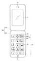
図1は、本発明を適用した折り畳み式の携帯無線端末100の外観形状を示す図であり、図1は、携帯無線端末100を開いた状態の図である。 FIG. 1 is a diagram showing the external shape of a foldable
携帯無線端末100は、図1に示すように、第1筐体である表示部側筐体10と、第2筐体である操作部側筐体20とを備えている。表示部側筐体10と操作部側筐体20とは、例えば、図示されないヒンジ部を介して連結されており、携帯無線端末100を開状態および閉状態に変更可能に構成されている。なお、携帯無線端末100を開状態とした場合、操作部側筐体20の側を下側、その反対を上側と呼称する。 As shown in FIG. 1, the portable
すなわち、ヒンジ部は、表示部側筐体10と操作部側筐体20とを、任意の角度で開閉可能に連結している。ここで、閉状態とは、表示部側筐体10と操作部側筐体20とが互いに重なるように配置された状態であり、開状態(図1)とは、表示部側筐体10と操作部側筐体20とが互いに重ならないように配置された状態を指す。 That is, the hinge part connects the display part side housing |
操作部側筐体20は、入力部としてキー操作部12を有している。ここで、キー操作部12は、電話番号の数字やメール等の文字等を入力するためのテンキー等の入力操作キー22、クリアーキー231や、電源キー232など、各種機能を作動させるための機能設定操作キー23、各種操作における決定や上下左右方向のスクロール等を行う決定操作キー24などを有している。 The operation
表示部側筐体10は、携帯無線端末100を開くことで露出する、表示部としてのディスプレイ11(表示部)を有している。また、表示部側筐体10には、音声出力部としてのスピーカ18が格納されており、スピーカ18は、ディスプレイ11が設けられた面の
上側端部近傍に設けられている。また、操作部側筐体20には、音声入力部としてのマイク19や格納されており、マイク19は、操作キー群25が設けられた面の下側端部近傍に設けられている。The display
<電気的構成>
図2は携帯無線端末100の電気的な構成を示すブロック図である。図2に示されるように、携帯無線端末100は、ディスプレイ11、キー操作部12、音声出力部(スピーカ)18、音声入力部(マイク)19、制御部30および無線通信部31を備えている。なお、制御部30および無線通信部31は、操作部側筐体20内に収められている。<Electrical configuration>
FIG. 2 is a block diagram showing an electrical configuration of the portable
制御部30は、CPU30aおよび記憶部30b等を備えており、キー操作部12の複数のキーによるキー入力による情報を処理するとともに、携帯無線端末100の他の構成要素を制御することによって、携帯無線端末100の動作を統括的に管理する。 The
記憶部30bは、ROMおよびRAM等で構成されている。記憶部30bは、キー操作部12などの入力部により受付けた入力を記憶する。後述するが、例えば、パスワード入力画面の表示の直前に、数字キーなどが入力されていた場合、その数字キーが入力されたことを記憶する。 The
制御部30の各種機能は、CPU30aが記憶部30b内の各種プログラムを実行することによって実現される。 Various functions of the
無線通信部31は、携帯無線端末100とは別の携帯無線端末や、インターネットに接続されたWebサーバ等の通信装置からの無線信号をアンテナ31aで受信し、受信信号に対して増幅処理やダウンコンバートを行って制御部30に出力する。また無線通信部31は、制御部30で生成された送信信号に対してアップコンバートや増幅処理を行って、アンテナ31aを通じて処理後の送信信号を、携帯無線端末100とは別の携帯無線端末や、インターネットに接続された通信装置に対して無線送信する。 The
音声入力部19は、外部から入力される音声を音声データに変換して制御部30に出力する。音声出力部18は、制御部30からの音声データを音声に変換して外部に出力する。 The
また、制御部30はキー制御部30cを有し、ダイアル操作防止機能(以後、ロック機能と呼称)が実行されている状況(ロックしている状況)では、所定のキー以外はキー操作を受け付けない構成となっている。 In addition, the
ディスプレイ11は、制御部30によって制御されることによって、文字、記号、図形などの各種情報を表示する。 The
なお、上述した携帯無線端末100においては、1つのディスプレイ11のみを有する構成として示したが、例えば表示部側筐体10のディスプレイ11が設けられた面とは反対側の面にディスプレイを有する構成であっても良い。また、キー操作部12は、押しボタン式のキーにより構成されるものとして説明したが、タッチパネル機能により実現されるタッチキー(ソフトウエアキー)により構成しても良い。その場合、1つのディスプレイを有する構成において、当該ディスプレイ上にタッチキーを表示する構成や、複数のディスプレイを有する構成において、1つのディスプレイにタッチキーを表示する構成を採ることができる。 In addition, in the portable
<機能実行コードの設定>
以下、図3を用いて、機能実行コードの設定方法について説明する。<Function execution code settings>
Hereinafter, the function execution code setting method will be described with reference to FIG.
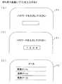
図3(a)には、所定のキー操作を経てディスプレイ11に表示された、機能画面選択ウインドウを示している。機能画面選択ウインドウ内には、「電話」を選択する項目13、「メール」を選択する項目14などが表示されているが、これは一例に過ぎない。 FIG. 3A shows a function screen selection window displayed on the
図3(a)では、「メール」を選択する例を示しており、項目14を選択して確定すると、次には、図3(b)に示すようなコード番号設定ウインドウが表示される。コード番号設定ウインドウには、機能画面選択ウインドウで選択した「メール」に対応付けるコード番号を入力する入力欄15があり、テンキーにより所定の数字を入力する。ここで、コード番号は、例えば0から9までの1桁の数字で設定され、図3(b)では「2」を設定する例を示している。なお、0から9までの1桁の数字で設定する場合は、機能実行コードによって実行させることができる機能は、最大で10種類となるが、もちろん、2桁の数字で設定するように構成しても良いことは言うまでもない。また、数字に限定されるものではなく、英文字を使用する構成としても良い。 FIG. 3A shows an example in which “mail” is selected. When the
コード番号設定ウインドウでコード番号を設定すると、図3(c)に示すようなコード/画面一覧ウインドウが表示される。コード/画面一覧ウインドウ内には、対応付けが終了した機能画面の名称と、それに対応するコード番号とが示されている。すなわち、コード番号1には「ブラウザ」が対応付けられ、コード番号2には「メール」が対応付けられ、コード番号3にはまだ機能の対応がなされていない。なお、コード番号は続き番号である必要はなく、ユーザの好みや、覚えやすい数字を設定すれば良い。 When the code number is set in the code number setting window, a code / screen list window as shown in FIG. 3C is displayed. In the code / screen list window, the name of the function screen that has been associated and the code number corresponding to it are shown. That is,
以上説明した機能実行コードの設定手順を経ることで、所望の機能画面とコード番号とを対応付けることができ、使い勝手の良い設定が可能となる。 Through the function execution code setting procedure described above, a desired function screen can be associated with a code number, and user-friendly setting is possible.
<動作>
次に、図4に示すフローチャートを用いて、実施の形態1に係るロック機能解除動作について説明する。<Operation>
Next, the lock function releasing operation according to the first embodiment will be described with reference to the flowchart shown in FIG.
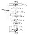
図2に示した制御部30においてロック機能が実行されると(ステップS1)、制御部30は入力されるのを待つことになる(ステップS2)。なお、ロック機能は、携帯無線端末100を閉じることで自動的に実行されるように設定することが可能である。 When the lock function is executed in the
入力がなされたことを検出した場合(ステップS2:YES)、図5(a)に示すように、パスワード入力画面を表示する(ステップS3)。なお、この場合、図3のように設定した「メール」の機能実行コードである「2」が待ち受け画面にて入力されたこととする。 When it is detected that an input has been made (step S2: YES), a password input screen is displayed as shown in FIG. 5A (step S3). In this case, it is assumed that “2”, which is a function execution code of “mail” set as shown in FIG. 3, is input on the standby screen.
図5(b)に示すようにパスワードが入力された後(ステップS4:YES)、制御部30はパスワードが正しいかどうかを判別する(ステップS5)。パスワードが正しくなければ(ステップS5:NO)ロック機能を維持し(ステップS6)、ステップS2に戻る。また、パスワードが正しければ(ステップS5:YES)ロック機能を解除する(ステップS7)。なお、図5(b)では入力したパスワードが数字で記載されているが、実際はプライバシーの観点から「****」などで表示される。 After the password is input as shown in FIG. 5B (step S4: YES), the
パスワードが入力される前に所定の文字(本例では、数字「2」)が入力されていたかどうか判別する(ステップS8)。所定の文字が入力されていなかった場合は(ステップS8:NO)、フローを終了する。所定の文字が入力されていた場合は(ステップS8:YES)、所定の文字に関連する機能を実行する(ステップS9)。この場合、入力した
数字「2」に紐づけられた「メール」機能に関する画面を図5(c)に示すように表示する。It is determined whether or not a predetermined character (number “2” in this example) has been input before the password is input (step S8). If a predetermined character has not been input (step S8: NO), the flow ends. If a predetermined character has been input (step S8: YES), a function related to the predetermined character is executed (step S9). In this case, a screen related to the “mail” function associated with the input number “2” is displayed as shown in FIG.
また、携帯無線端末によっては、待ち受け画面が表示されているときに、ユーザが文字を入力することによってパスワード入力画面が表示されたとき、パスワード入力画面の表示とともに、ユーザが入力した文字がパスワードの1文字目として入力されてしまう場合がある。そのような場合の具体例を図6および7を用いて以下に説明する。 In addition, depending on the mobile wireless terminal, when the password input screen is displayed by the user entering characters while the standby screen is displayed, the password entered by the user is displayed along with the password input screen. It may be input as the first character. A specific example in such a case will be described below with reference to FIGS.
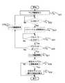
図6におけるステップS1〜S3は図4の場合と同様であるため省略する。図6の場合、待ち受け画面にてユーザが数字キー「2」を押したとき、表示されたパスワード入力画面には1文字目に、図7(a)に示すようにユーザが入力した機能実行コードである数字「2」が入力されている(ステップS10)。なお、実際はプライバシーの観点から「*」などで表示される。 Steps S1 to S3 in FIG. 6 are the same as those in FIG. In the case of FIG. 6, when the user presses the numeric key “2” on the standby screen, the function execution code input by the user as shown in FIG. The number “2” is input (step S10). Actually, “*” is displayed from the viewpoint of privacy.
パスワード入力画面において数字「2」が入力されており、さらにユーザはパスワードの1文字目が「2」でなかった場合、図7(b)および図6のステップS10に示すように、ユーザは入力された1文字目を削除するはずである。そのため、本例ではステップS11において、パスワード入力画面から数字が削除されたかどうかを判別する。 When the number “2” is input on the password input screen and the first character of the password is not “2”, the user inputs as shown in step S10 of FIG. 7B and FIG. The first character should be deleted. Therefore, in this example, in step S11, it is determined whether or not the number has been deleted from the password input screen.
もし、図7(c)に示すように表示するように、削除することなく、そのままパスワードが入力された場合(ステップS11:NO、ステップS12:YES)、パスワードが正しいかどうかを判別する(ステップS13)。パスワードが正しくなければ(ステップS13:NO)、ロック機能を維持する(ステップS14)。一方、パスワードが正しければ(ステップS13:YES)、ユーザはパスワードを入力するために「2」を入力したことが想定されるため、ロック機能を解除して終了する(ステップS15)。 If the password is input as it is without being deleted as shown in FIG. 7C (step S11: NO, step S12: YES), it is determined whether the password is correct (step S11). S13). If the password is not correct (step S13: NO), the lock function is maintained (step S14). On the other hand, if the password is correct (step S13: YES), it is assumed that the user has input “2” to input the password, so the lock function is released and the process ends (step S15).
パスワード入力画面から数字が削除された場合(ステップS11:YES)、その後パスワードが入力され(ステップS16:YES)、パスワードが正しい場合(ステップS17:YES)、ロック機能を解除する(ステップS18)。 If the number is deleted from the password input screen (step S11: YES), then the password is input (step S16: YES), and if the password is correct (step S17: YES), the lock function is released (step S18).
ロック機能を解除した後、初めに入力された数字がパスワードの1文字目と異なるかどうかを判別する(ステップS19)。違う場合(ステップS19:YES)、所定の文字に関連する機能を実行する(ステップS9)。この場合、入力した数字「2」に紐づけられた「メール」機能に関する画面を図7(d)に示すように表示する(ステップS20)。 After releasing the lock function, it is determined whether or not the first input number is different from the first character of the password (step S19). If they are different (step S19: YES), a function related to a predetermined character is executed (step S9). In this case, a screen related to the “mail” function associated with the input number “2” is displayed as shown in FIG. 7D (step S20).
一方、初めに入力された数字がパスワードの1文字目と同じ場合(ステップS19:NO)、ステップS11にてパスワード入力画面から数字が削除されたのは、ユーザの操作間違いであった可能性が高いため、そのまま処理を終了する。 On the other hand, if the first input number is the same as the first character of the password (step S19: NO), it is possible that the number was deleted from the password input screen in step S11 because of a user operation error. Since it is high, the process is terminated as it is.
以上説明したように、ユーザがロック機能を設定したことを忘れていたときに、所定の機能を立ち上げようとして、キーを押したとき、パスワード入力を促す画面が出てきた場合、パスワードを入力するだけで、所定の機能を立ち上げることができる。このため、ユーザにとって使い勝手が良くなるという効果が得られる。 As explained above, when the user has forgotten that the lock function has been set and the user is prompted to enter the password when pressing a key to start the specified function, enter the password. By simply doing, a predetermined function can be started up. For this reason, the effect that usability improves for a user is acquired.
上記例では、1つの数字キーを押したときにパスワード入力画面の表示が立ち上がったが、例えば、文字キーとは別のキー(たとえば、メニューキーなど)を押したうえで、文字キーを押したときに初めてパスワード入力画面の表示画面が立ち上がるように、2つ以上のキーを押す場合も適用することができる。 In the above example, the password entry screen is displayed when one numeric key is pressed. For example, after pressing a key other than the character key (for example, the menu key), the character key is pressed. The present invention can also be applied to a case where two or more keys are pressed so that a password input screen display screen is displayed for the first time.
なお、実施の形態1では、図3に示すように、ユーザが機能実行コードを設定したが、あらかじめ所定の機能に割り当てられた専用のキーを端末が持っていてもよい。また、後述の実施の形態2にて説明する内容と同じように、キーの「短押し」と「長押し」を区別して、長押しに所定の機能が割り当てられていてもよい。 In the first embodiment, as shown in FIG. 3, the user sets the function execution code, but the terminal may have a dedicated key assigned in advance to a predetermined function. Similarly to the contents described in the second embodiment to be described later, a predetermined function may be assigned to long press by distinguishing between “short press” and “long press” of a key.
[実施の形態2]
以上説明した実施の形態1においては、折り畳み式の携帯無線端末100を例に採り、ハードウエアとしてのキーによりパスワードやコード番号を入力する構成を示したが、少なくとも1つのタッチパネルを有し、そこに表示されたソフトウエアキーによりパスワードやコード番号を入力する携帯無線端末に対しても適用可能であることは言うまでもない。[Embodiment 2]
In the first embodiment described above, the foldable
また、タッチパネルを有する携帯無線端末においては、パスワードやコード番号を入力する代わりに、指等の指示体による所定のタッチ操作をもってロックを解除する構成を採っても良い。 Moreover, in the portable wireless terminal having a touch panel, a configuration may be adopted in which the lock is released by a predetermined touch operation with an indicator such as a finger instead of inputting a password or a code number.
図8には、タッチパネルを有する携帯無線端末の一例の外観形状を示す。図8に示す携帯無線端末200は、筐体40に設けたディスプレイ41が常に露出した状態の端末であり、図8はそれをディスプレイ41側から見た平面図である。 FIG. 8 shows an appearance of an example of a portable wireless terminal having a touch panel. A
筐体40の、ディスプレイ41が設けられた側の面内には、音声入力部としてのマイク43や音声出力部としてのスピーカ44が格納されており、マイク43およびスピーカ44は、ディスプレイ41が露出する面の長手方向の両端部近傍に設けられている。 A
なお、ディスプレイ41には、タッチパネルにより実現される複数のキーが表示される構成となっている。図8の例では、1つ前の画面に戻るバックキー421、各画面に対応したオプションメニューを表示させるメニューキー422およびホーム画面に戻るホームキー423を表示している。 The
接触操作を受け付けるタッチパネルは、ディスプレイ41上に位置し、ディスプレイ41の領域にもオーバーラップするように設けられ、ダイヤルキーやアルファベットキーなどをソフトウエアキーとしてディスプレイ41上で機能させることができる。 The touch panel that accepts the contact operation is located on the
なお、ディスプレイ41上で機能するタッチパネル機能は、筐体40内に収納された制御部(図示せず)によって制御され、ユーザの指等の指示体による操作は、タッチパネルによるタッチパネル機能を介して検出され、制御部に出力される。 In addition, the touch panel function which functions on the
このようなタッチパネルを有する携帯無線端末200において、指等の指示体による所定のタッチ操作によりロックを解除する動作について、図9〜12を用いて説明する。 An operation of releasing the lock by a predetermined touch operation with an indicator such as a finger in the
制御部30においてロック機能が実行されると(ステップS21)、制御部30は接触による入力されるのを待つことになる(ステップS22)。接触による入力がなされたことを検出した場合(ステップS22:YES)、図10(a)に示すように、パスワード入力画面を表示する(ステップS23)。 When the lock function is executed in the control unit 30 (step S21), the
なお、この場合、待ち受け画面にて接触操作によりメールアイコンが選択されたこととする。 In this case, it is assumed that the mail icon is selected by the contact operation on the standby screen.
図10(b)に示すようにパスワードが入力された後(ステップS24:YES)、制御部30はパスワードが正しいかどうかを判別する(ステップS25)。パスワードが正
しくなければ(ステップS25:NO)ロック機能を維持し(ステップS26)、ステップS22に戻る。また、パスワードが正しければ(ステップS25:YES)ロック機能を解除する(ステップS27)。After the password is input as shown in FIG. 10B (step S24: YES), the
次に、パスワードが入力される前に、所定のアイコンに対して接触操作がなされていたかどうか判別する(ステップS28)。所定のアイコンに対して接触操作がなされていなかった場合は(ステップS28:NO)、フローを終了する。一方、所定のアイコンに対して接触操作がなされていた場合は(ステップS28:YES)、所定のアイコンに関連する機能を実行する(ステップS29)。この場合、所定のアイコンであるメールアイコンに紐づけられた「メール」機能に関する画面を図10(c)に示すように表示する。 Next, it is determined whether or not a touch operation has been performed on a predetermined icon before the password is input (step S28). If no contact operation has been performed on the predetermined icon (step S28: NO), the flow ends. On the other hand, if a contact operation has been performed on the predetermined icon (step S28: YES), a function related to the predetermined icon is executed (step S29). In this case, a screen related to the “mail” function associated with a predetermined mail icon is displayed as shown in FIG.
なお、タッチパネルを有する携帯無線端末では、所定のアイコンに指などが接触してから離れるまでの時間が所定の時間以内か所定の時間を超えるか(短押しか長押しか)を判別するものが知られている。本発明において、例えば、図9におけるステップS28とステップS29との間に、図11に示すように、接触操作が短押しかそうでないかを判別するステップを入れてもよい(ステップS30)。接触操作が短押しであれば(ステップS30:YES)、フローは図9におけるステップS29に移行する。一方、接触操作が短押しでなく、長押しであれば(ステップS30:NO)、所定のアイコン、本例では、図12(c)に示すように、メールアイコンを移動可能にし(ステップS31)、処理を終了する。なお、図12(c)では、メールアイコンの外枠を点線にして、移動可能であることを示しているが、本発明はこれに限定されない。 A portable wireless terminal having a touch panel is known that determines whether the time from when a finger or the like touches a predetermined icon until it leaves is within a predetermined time or exceeds a predetermined time (short press or long press). It has been. In the present invention, for example, as shown in FIG. 11, a step of determining whether the touch operation is a short press or not may be inserted between step S28 and step S29 in FIG. 9 (step S30). If the contact operation is a short press (step S30: YES), the flow proceeds to step S29 in FIG. On the other hand, if the contact operation is not a short press but a long press (step S30: NO), a predetermined icon, in this example, a mail icon is made movable as shown in FIG. 12C (step S31). The process is terminated. In FIG. 12C, the outer frame of the mail icon is indicated by a dotted line to indicate that it can be moved, but the present invention is not limited to this.
また、上記例では、短押しでアイコンの機能を選択、長押しでアイコンの移動をさせることを説明したが、あくまで一例にすぎない
なお、実施の形態2では、タッチパネルを有する携帯無線端末200における「短押し」および「長押し」を説明したが、実施の形態1に示す入力操作キー22を有する携帯無線端末100において、「短押し」および「長押し」で異なる機能処理が割り当てられている場合も、図11および12に示す例を適用してもよい。In the above example, the function of the icon is selected by a short press and the icon is moved by a long press. However, this is only an example. In the second embodiment, the
11、41 ディスプレイ
18、44 スピーカ
19、43 マイク
22 入力操作キー
30 制御部
100、200 携帯無線端末11, 41
Claims (3)
Translated fromJapanese前記メール機能を処理するための前記メール関連表示への接触操作による入力を受け付ける入力部と、
前記入力部により受け付けた入力を記憶する記憶部と、
前記表示部の表示を制御するとともに、前記入力部により受け付けた入力に関するメール機能を処理する制御部と、を備え、
前記制御部は、
前記メール機能の処理が制限されているときに、
アイコンへの第一の接触操作による入力を受け付けると前記表示部にパスワード入力のための複数の文字を表示させ、前記パスワードが正しく入力された場合、前記表示部に第一の機能を実行でき、
前記アイコンに対して前記第一の接触操作とは異なる第二の接触操作による入力を受け付けると前記表示部にパスワード入力のための複数の文字を表示させ、前記パスワードが正しく入力された場合、前記第一の機能とは異なる第二の機能を実行できる、電子機器。A display section that can display the mail related display linked to the mail function;
An input unit that accepts an input by a contact operation to the mail related display for processing the mail function;
A storage unit for storing the input received by the input unit;
A control unit that controls the display of the display unit and processes a mail function related to the input received by the input unit,
The controller is
When the processing of the email function is restricted,
When an input by the first contact operation to the icon is received, a plurality of characters for password input are displayed on the display unit, and when the password is correctly input, the first function can be executed on the display unit,
When an input by a second contact operation different from the first contact operation is received for the icon, a plurality of characters for password input are displayed on the display unit, and when the password is correctly input, An electronic device capable of executing a second function different from the first function.
前記アイコンへの前記第一の接触操作による入力を受け付けたとき、前記表示部に前記メール機能を表示でき、
前記アイコンへの前記第二の接触操作による入力を受け付けたとき、前記メール機能とは異なる前記機能を実行できる、請求項1記載の電子機器。When the processing of the email function is not restricted,
When the input by the first contact operation to the icon is accepted, the mail function can be displayed on the display unit,
The electronic device according to claim 1, wherein when an input by the second contact operation to the icon is received, the function different from the mail function can be executed.
Priority Applications (1)
| Application Number | Priority Date | Filing Date | Title |
|---|---|---|---|
| JP2016131392AJP6190006B2 (en) | 2016-07-01 | 2016-07-01 | Electronics |
Applications Claiming Priority (1)
| Application Number | Priority Date | Filing Date | Title |
|---|---|---|---|
| JP2016131392AJP6190006B2 (en) | 2016-07-01 | 2016-07-01 | Electronics |
Related Parent Applications (1)
| Application Number | Title | Priority Date | Filing Date |
|---|---|---|---|
| JP2011210515ADivisionJP6001249B2 (en) | 2011-09-27 | 2011-09-27 | Electronics |
Publications (2)
| Publication Number | Publication Date |
|---|---|
| JP2016192796Atrue JP2016192796A (en) | 2016-11-10 |
| JP6190006B2 JP6190006B2 (en) | 2017-08-30 |
Family
ID=57246865
Family Applications (1)
| Application Number | Title | Priority Date | Filing Date |
|---|---|---|---|
| JP2016131392AExpired - Fee RelatedJP6190006B2 (en) | 2016-07-01 | 2016-07-01 | Electronics |
Country Status (1)
| Country | Link |
|---|---|
| JP (1) | JP6190006B2 (en) |
Citations (6)
| Publication number | Priority date | Publication date | Assignee | Title |
|---|---|---|---|---|
| JPH09330175A (en)* | 1996-06-11 | 1997-12-22 | Hitachi Ltd | Information processing apparatus and operating method thereof |
| JPH11112639A (en)* | 1997-10-06 | 1999-04-23 | Toshiba Corp | Mobile radio terminal and control method therefor |
| JP2004038260A (en)* | 2002-06-28 | 2004-02-05 | Clarion Co Ltd | Information processor, information processing method and program |
| JP2006244427A (en)* | 2005-03-07 | 2006-09-14 | Canon Inc | Information processing apparatus, control apparatus, printing system, information processing method, and program |
| JP2010011233A (en)* | 2008-06-27 | 2010-01-14 | Kyocera Corp | Portable terminal device, function start control method, and program |
| JP2013074379A (en)* | 2011-09-27 | 2013-04-22 | Kyocera Corp | Electronic apparatus |
- 2016
- 2016-07-01JPJP2016131392Apatent/JP6190006B2/ennot_activeExpired - Fee Related
Patent Citations (6)
| Publication number | Priority date | Publication date | Assignee | Title |
|---|---|---|---|---|
| JPH09330175A (en)* | 1996-06-11 | 1997-12-22 | Hitachi Ltd | Information processing apparatus and operating method thereof |
| JPH11112639A (en)* | 1997-10-06 | 1999-04-23 | Toshiba Corp | Mobile radio terminal and control method therefor |
| JP2004038260A (en)* | 2002-06-28 | 2004-02-05 | Clarion Co Ltd | Information processor, information processing method and program |
| JP2006244427A (en)* | 2005-03-07 | 2006-09-14 | Canon Inc | Information processing apparatus, control apparatus, printing system, information processing method, and program |
| JP2010011233A (en)* | 2008-06-27 | 2010-01-14 | Kyocera Corp | Portable terminal device, function start control method, and program |
| JP2013074379A (en)* | 2011-09-27 | 2013-04-22 | Kyocera Corp | Electronic apparatus |
Also Published As
| Publication number | Publication date |
|---|---|
| JP6190006B2 (en) | 2017-08-30 |
Similar Documents
| Publication | Publication Date | Title |
|---|---|---|
| US20110247065A1 (en) | Simultaneous screen unlock and operation initiation | |
| KR101400646B1 (en) | Terminal And Method Of Providing For Analog Dial Lock In Mobile Terminal with Touch Screen | |
| JP5030564B2 (en) | Mobile phone and control method thereof | |
| WO2013035744A1 (en) | Terminal device, information input method, and program | |
| US20100245272A1 (en) | Mobile terminal apparatus and method of starting application | |
| JP5666114B2 (en) | Electronics | |
| US6295441B1 (en) | Input device and method of entering data into an electronic apparatus | |
| JP5592245B2 (en) | Electronics | |
| JP6001249B2 (en) | Electronics | |
| JP6190006B2 (en) | Electronics | |
| JP4163721B2 (en) | Wireless communication terminal, application display method and program | |
| KR100690733B1 (en) | Keypad Definition System and Method for Mobile Communication Terminal | |
| US20150248545A1 (en) | Sign shortcut | |
| JP5228736B2 (en) | Mobile phone | |
| KR100806502B1 (en) | How to search menu by function through text input in mobile communication terminal | |
| JP3546407B2 (en) | Electronic device password authentication method | |
| JP2004220618A (en) | Electronic device password authentication method | |
| JP2924899B2 (en) | Electronic equipment and communication terminal equipment | |
| JP2011114718A (en) | Portable electronic device and method for controlling the same | |
| JP3011189B2 (en) | Telephone device and wireless telephone device | |
| JP2003099178A (en) | Auxiliary keyboard input device and information processing device to which the device can be attached | |
| KR101169645B1 (en) | Method and Appratus for Smart Dial of Mobile Communication Terminal | |
| KR20050090720A (en) | Bookmark menu institution method of mobile communicator | |
| JP2012213204A (en) | Electronic apparatus | |
| JPH118682A (en) | Electronic equipment and wireless communication devices |
Legal Events
| Date | Code | Title | Description |
|---|---|---|---|
| A977 | Report on retrieval | Free format text:JAPANESE INTERMEDIATE CODE: A971007 Effective date:20170418 | |
| A131 | Notification of reasons for refusal | Free format text:JAPANESE INTERMEDIATE CODE: A131 Effective date:20170425 | |
| A521 | Request for written amendment filed | Free format text:JAPANESE INTERMEDIATE CODE: A523 Effective date:20170622 | |
| TRDD | Decision of grant or rejection written | ||
| A01 | Written decision to grant a patent or to grant a registration (utility model) | Free format text:JAPANESE INTERMEDIATE CODE: A01 Effective date:20170704 | |
| A61 | First payment of annual fees (during grant procedure) | Free format text:JAPANESE INTERMEDIATE CODE: A61 Effective date:20170803 | |
| R150 | Certificate of patent or registration of utility model | Ref document number:6190006 Country of ref document:JP Free format text:JAPANESE INTERMEDIATE CODE: R150 | |
| LAPS | Cancellation because of no payment of annual fees |