JP2016192122A - Information processing device, information processing method, and program - Google Patents
Information processing device, information processing method, and programDownload PDFInfo
- Publication number
- JP2016192122A JP2016192122AJP2015072407AJP2015072407AJP2016192122AJP 2016192122 AJP2016192122 AJP 2016192122AJP 2015072407 AJP2015072407 AJP 2015072407AJP 2015072407 AJP2015072407 AJP 2015072407AJP 2016192122 AJP2016192122 AJP 2016192122A
- Authority
- JP
- Japan
- Prior art keywords
- user
- image
- hand
- information
- information processing
- Prior art date
- Legal status (The legal status is an assumption and is not a legal conclusion. Google has not performed a legal analysis and makes no representation as to the accuracy of the status listed.)
- Pending
Links
Images


Classifications
- G—PHYSICS
- G06—COMPUTING OR CALCULATING; COUNTING
- G06T—IMAGE DATA PROCESSING OR GENERATION, IN GENERAL
- G06T11/00—2D [Two Dimensional] image generation
- G06T11/60—Editing figures and text; Combining figures or text
- G—PHYSICS
- G06—COMPUTING OR CALCULATING; COUNTING
- G06F—ELECTRIC DIGITAL DATA PROCESSING
- G06F3/00—Input arrangements for transferring data to be processed into a form capable of being handled by the computer; Output arrangements for transferring data from processing unit to output unit, e.g. interface arrangements
- G06F3/01—Input arrangements or combined input and output arrangements for interaction between user and computer
- G06F3/011—Arrangements for interaction with the human body, e.g. for user immersion in virtual reality
- G06F3/013—Eye tracking input arrangements
- G—PHYSICS
- G06—COMPUTING OR CALCULATING; COUNTING
- G06F—ELECTRIC DIGITAL DATA PROCESSING
- G06F3/00—Input arrangements for transferring data to be processed into a form capable of being handled by the computer; Output arrangements for transferring data from processing unit to output unit, e.g. interface arrangements
- G06F3/01—Input arrangements or combined input and output arrangements for interaction between user and computer
- G06F3/017—Gesture based interaction, e.g. based on a set of recognized hand gestures
- G—PHYSICS
- G06—COMPUTING OR CALCULATING; COUNTING
- G06F—ELECTRIC DIGITAL DATA PROCESSING
- G06F3/00—Input arrangements for transferring data to be processed into a form capable of being handled by the computer; Output arrangements for transferring data from processing unit to output unit, e.g. interface arrangements
- G06F3/01—Input arrangements or combined input and output arrangements for interaction between user and computer
- G06F3/03—Arrangements for converting the position or the displacement of a member into a coded form
- G06F3/033—Pointing devices displaced or positioned by the user, e.g. mice, trackballs, pens or joysticks; Accessories therefor
- G06F3/0346—Pointing devices displaced or positioned by the user, e.g. mice, trackballs, pens or joysticks; Accessories therefor with detection of the device orientation or free movement in a 3D space, e.g. 3D mice, 6-DOF [six degrees of freedom] pointers using gyroscopes, accelerometers or tilt-sensors
- G—PHYSICS
- G06—COMPUTING OR CALCULATING; COUNTING
- G06F—ELECTRIC DIGITAL DATA PROCESSING
- G06F3/00—Input arrangements for transferring data to be processed into a form capable of being handled by the computer; Output arrangements for transferring data from processing unit to output unit, e.g. interface arrangements
- G06F3/01—Input arrangements or combined input and output arrangements for interaction between user and computer
- G06F3/048—Interaction techniques based on graphical user interfaces [GUI]
- G06F3/0481—Interaction techniques based on graphical user interfaces [GUI] based on specific properties of the displayed interaction object or a metaphor-based environment, e.g. interaction with desktop elements like windows or icons, or assisted by a cursor's changing behaviour or appearance
- G06F3/04815—Interaction with a metaphor-based environment or interaction object displayed as three-dimensional, e.g. changing the user viewpoint with respect to the environment or object
- G—PHYSICS
- G06—COMPUTING OR CALCULATING; COUNTING
- G06F—ELECTRIC DIGITAL DATA PROCESSING
- G06F3/00—Input arrangements for transferring data to be processed into a form capable of being handled by the computer; Output arrangements for transferring data from processing unit to output unit, e.g. interface arrangements
- G06F3/01—Input arrangements or combined input and output arrangements for interaction between user and computer
- G06F3/048—Interaction techniques based on graphical user interfaces [GUI]
- G06F3/0484—Interaction techniques based on graphical user interfaces [GUI] for the control of specific functions or operations, e.g. selecting or manipulating an object, an image or a displayed text element, setting a parameter value or selecting a range
- H—ELECTRICITY
- H04—ELECTRIC COMMUNICATION TECHNIQUE
- H04N—PICTORIAL COMMUNICATION, e.g. TELEVISION
- H04N5/00—Details of television systems
- H04N5/64—Constructional details of receivers, e.g. cabinets or dust covers
Landscapes
- Engineering & Computer Science (AREA)
- Theoretical Computer Science (AREA)
- General Engineering & Computer Science (AREA)
- Physics & Mathematics (AREA)
- General Physics & Mathematics (AREA)
- Human Computer Interaction (AREA)
- Multimedia (AREA)
- Signal Processing (AREA)
- User Interface Of Digital Computer (AREA)
Abstract
Description
Translated fromJapanese本開示は、情報処理装置、情報処理方法、およびプログラムに関する。 The present disclosure relates to an information processing apparatus, an information processing method, and a program.
近年、メガネ型のウェアラブル機器が注目されている。このようなメガネ型のウェアラブル機器では、コンテンツなどのオブジェクトは、手などを用いたジェスチャ動作によって操作されることが一般的である。 In recent years, eyewear-type wearable devices have attracted attention. In such a glasses-type wearable device, an object such as content is generally operated by a gesture operation using a hand or the like.
例えば、下記の特許文献1には、周囲環境および表示されたコンテンツの両方をユーザが視認可能なメガネ型のウェアラブル端末が開示されている。また、特許文献1には、ユーザの手または周囲の物体に仮想キーボードを映写し、映写された仮想キーボードに対するユーザのタイプ動作を取得することで、ユーザからの入力情報を取得することが開示されている。 For example,
しかし、特許文献1等に開示されたメガネ型のウェアラブル端末では、オブジェクト操作のためのジェスチャ動作により、ユーザの視野が制限されることがあった。 However, in the glasses-type wearable terminal disclosed in
例えば、ユーザがオブジェクト操作を行う場合、ユーザの視野内にジェスチャ動作を行う手が入り込むため、ユーザは手の後方に存在する風景を視認することは困難であった。また、ユーザが仮想キーボードをタイプする場合、仮想キーボードのキーがタイプする手で隠れてしまうため、ユーザは、タイプするキーを確認することは困難であった。 For example, when a user performs an object operation, a hand performing a gesture operation enters the user's field of view, and thus it is difficult for the user to visually recognize a landscape existing behind the hand. Further, when the user types the virtual keyboard, the key of the virtual keyboard is hidden by the typing hand, and thus it is difficult for the user to confirm the key to be typed.
そこで、本開示では、視野内にユーザの手が入り込んだ場合でもユーザの視野を確保することが可能な、新規かつ改良された情報処理装置、情報処理方法、およびプログラムを提案する。 Therefore, the present disclosure proposes a new and improved information processing apparatus, information processing method, and program capable of ensuring the user's visual field even when the user's hand enters the visual field.
本開示によれば、ユーザの視野に相当する視野画像を取得する画像取得部と、前記視野画像の中から前記ユーザの手を検出する手検出部と、前記視野画像に基づいて、前記手により前記ユーザが目視できない背景の背景画像を生成する背景画像生成部と、前記ユーザの視野内の前記手が占める領域に前記背景画像を重畳させた表示画像を生成する出力画像生成部と、を備える、情報処理装置が提供される。 According to the present disclosure, an image acquisition unit that acquires a visual field image corresponding to the visual field of the user, a hand detection unit that detects the user's hand from the visual field image, and the hand based on the visual field image. A background image generation unit that generates a background image of a background that is not visible to the user, and an output image generation unit that generates a display image in which the background image is superimposed on an area occupied by the hand in the field of view of the user. An information processing apparatus is provided.
また、本開示によれば、ユーザの視野に相当する視野画像を取得することと、前記視野画像の中から前記ユーザの手を検出することと、前記視野画像に基づいて、前記手により前記ユーザが目視できない背景の背景画像を生成することと、前記ユーザの視野内の前記手が占める領域に前記背景画像を重畳させた表示画像を生成することと、を含む情報処理方法が提供される。 In addition, according to the present disclosure, the field of view corresponding to the field of view of the user is acquired, the user's hand is detected from the field of view, and the user is moved by the hand based on the field of view image. An information processing method is provided that includes generating a background image of a background that cannot be viewed, and generating a display image in which the background image is superimposed on an area occupied by the hand within the field of view of the user.
また、本開示によれば、コンピュータをユーザの視野に相当する視野画像を取得する画像取得部と、前記視野画像の中から前記ユーザの手を検出する手検出部と、前記視野画像に基づいて、前記手により前記ユーザが目視できない背景の背景画像を生成する背景画像生成部と、前記ユーザの視野内の前記手が占める領域に前記背景画像を重畳させた表示画像を生成する出力画像生成部と、として機能させるプログラムが提供される。 Further, according to the present disclosure, the computer is configured to acquire an image acquisition unit that acquires a visual field image corresponding to the visual field of the user, a hand detection unit that detects the user's hand from the visual field image, and the visual field image A background image generation unit that generates a background image of a background that cannot be seen by the user by the hand, and an output image generation unit that generates a display image in which the background image is superimposed on an area occupied by the hand in the field of view of the user And a program that functions as:
本開示によれば、ジェスチャ動作をしている手によって隠され、ユーザが目視できない背景の画像をユーザの手に重畳させて表示させることができる。したがって、本開示に係る情報処理装置は、ユーザに対して、あたかもジェスチャ動作をしている手が消去されたかのような視野を視認させることが可能である。 According to the present disclosure, it is possible to display a background image that is hidden by a hand performing a gesture operation and is not visible to the user, superimposed on the user's hand. Therefore, the information processing apparatus according to the present disclosure can allow the user to visually recognize the field as if the hand performing the gesture operation has been erased.
以上説明したように本開示によれば、ユーザの視野を確保することが可能である。 As described above, according to the present disclosure, it is possible to secure the user's visual field.
なお、上記の効果は必ずしも限定的なものではなく、上記の効果とともに、または上記の効果に代えて、本明細書に示されたいずれかの効果、または本明細書から把握され得る他の効果が奏されてもよい。 Note that the above effects are not necessarily limited, and any of the effects shown in the present specification, or other effects that can be grasped from the present specification, together with or in place of the above effects. May be played.
以下に添付図面を参照しながら、本開示の好適な実施の形態について詳細に説明する。なお、本明細書及び図面において、実質的に同一の機能構成を有する構成要素については、同一の符号を付することにより重複説明を省略する。 Hereinafter, preferred embodiments of the present disclosure will be described in detail with reference to the accompanying drawings. In addition, in this specification and drawing, about the component which has the substantially same function structure, duplication description is abbreviate | omitted by attaching | subjecting the same code | symbol.
なお、説明は以下の順序で行うものとする。
1.本開示の一実施形態に係る情報処理装置
1.1.情報処理装置の概要
1.2.情報処理装置の構成
1.3.情報処理装置の制御
2.変形例
2.1.情報処理装置の構成
2.2.情報処理装置の制御
2.3.ユーザが視認する視野の一例
3.ハードウェア構成
4.まとめThe description will be made in the following order.
1. Information processing apparatus according to an embodiment of the present disclosure 1.1. Outline of information processing apparatus 1.2. Configuration of information processing apparatus 1.3. Control of information processing apparatus Modification 2.1. Configuration of information processing apparatus 2.2. Control of information processing apparatus 2.3. An example of a visual field visually recognized by the user. Hardware configuration Summary
<1.本開示の一実施形態>
[1.1.情報処理装置の概要]
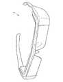
まず、図1を参照して、本開示の一実施形態に係る情報処理装置1の外観例について説明する。図1は、本実施形態に係る情報処理装置1の外観例を示す斜視図である。<1. One Embodiment of the Present Disclosure>
[1.1. Overview of information processing equipment]
First, an external appearance example of the
図1に示すように、本実施形態に係る情報処理装置1は、例えば、メガネ型のウェアラブル端末装置である。このようなメガネ型のウェアラブル端末装置は、例えば、透過型の表示装置を備える。これにより、情報処理装置1は、ユーザに対して、ウェアラブル端末装置が表示する画像と、ユーザ自身の視覚が捉えた画像とを重畳させて視認させることができる。 As illustrated in FIG. 1, the
また、情報処理装置1は、ユーザがコンテンツ等の各種オブジェクトを直感的に操作することを可能にするために、ユーザのジェスチャ動作を認識し、認識したジェスチャ動作に対応した操作を各種オブジェクトに対して実行する。 In addition, the
ただし、メガネ型のウェアラブル端末装置は、ユーザの視野が狭いため、ユーザがジェスチャ動作によってオブジェクトを操作する場合、ジェスチャ動作を行う手によりユーザの視野が遮蔽され、ユーザが手の後方にある背景を目視できなくなることがあった。また、このようなジェスチャ操作は、ユーザの至近で行われるため、操作対象であるオブジェクトが小さい場合、該オブジェクトが手によって隠れてしまい、オブジェクトの操作が困難になることがあった。 However, since the glasses-type wearable terminal device has a narrow field of view of the user, when the user manipulates an object by a gesture operation, the user's field of view is shielded by the hand that performs the gesture operation, and the user has a background behind the hand. Sometimes it could not be seen. In addition, since such a gesture operation is performed close to the user, when an object to be operated is small, the object may be hidden by a hand, and it may be difficult to operate the object.
本実施形態に係る情報処理装置1は、各種センサ(例えば、撮像装置など)にてユーザの視野に相当する画像を取得し、取得した視野内の画像に基づいて、手によってユーザが目視できない背景の画像を生成する。また、情報処理装置1は、ユーザから背景を遮蔽している手に対して、生成した背景の画像を重畳して表示させる。これにより、情報処理装置1は、ユーザに対して、視野内からジェスチャ動作等をしている手が消去されたかのような画像を視認させることができるため、ユーザの視野を確保することができる。 The
なお、情報処理装置1は、表示装置を備えていなくともよい。情報処理装置1が表示装置を備えていない場合、情報処理装置1は、例えば、外部接続された表示装置に生成した表示画像を出力し、表示画像は外部の表示装置により表示される。 Note that the
以下では、上記で概要を説明した本実施形態に係る情報処理装置1の構成について、詳細に説明する。 Below, the structure of the
[1.2.情報処理装置の構成]
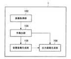
次に、図2〜図4を参照して、本実施形態に係る情報処理装置1の構成例について説明する。図2は、本実施形態に係る情報処理装置1の内部構成を示したブロック図である。[1.2. Configuration of information processing apparatus]
Next, a configuration example of the
図2に示すように、本実施形態に係る情報処理装置1は、画像取得部102と、手検出部104と、背景画像生成部106と、出力画像生成部108とを備える。 As illustrated in FIG. 2, the
画像取得部102は、ユーザの視野に相当する視野画像を取得する。具体的には、画像取得部102は、情報処理装置1に装着された撮像装置(図示せず)などが撮像した画像を取得する。画像取得部102が取得する画像は、ユーザの視野に相当する領域を含む画像であればよく、ユーザの視野に相当する領域よりも広い領域の画像であってもよい。 The
手検出部104は、画像取得部102が取得した画像中からユーザの手を検出する。具体的には、手検出部104は、事前学習により手の形状を表す検出パラメータを記憶しており、該検出パラメータに基づいて、画像取得部102が取得した画像中からユーザの手を検出する。また、手検出部104は、検出したユーザの手が占める領域を特定するパラメータを出力する。なお、手検出部104が検出するユーザの手は、ジェスチャ動作をしている手に限定されず、ジェスチャ動作をしていない手を含む。 The
手検出部104は、例えば、事前に複数用意された様々な角度の手の画像を基に輪郭情報および輝度情報などを検出パラメータとして機械学習しておくことにより、画像中からユーザの手を検出することが可能である。また、機械学習のアルゴリズムとしては、公知の方法を用いることが可能であるが、例えば、サポートベクターマシン、ニューラルネットワークなどのアルゴリズムを用いることが可能である。 For example, the
背景画像生成部106は、画像取得部102が取得した視野画像に基づいて、手によってユーザが目視できない背景に相当する背景画像を生成する。例えば、背景画像生成部106は、撮像装置の視差を用いてユーザが目視できない背景に相当する背景画像を生成してもよい。また、背景画像生成部106は、時系列画像を用いてユーザが目視できない背景に相当する背景画像を生成してもよい。 The background
ここで、図3Aおよび3Bを参照して、背景画像生成部106が、画像取得部102が取得した視野画像に基づいて背景画像を生成する具体的な方法について説明する。図3Aは、撮像装置の視差を用いて背景画像を生成する方法を説明する説明図である。また、図3Bは、時系列画像を用いて背景画像を生成する方法を説明する説明図である。 Here, a specific method in which the background
撮像装置の視差を用いて背景画像を生成する場合、例えば、図3Aに示すように、画像取得部102は、複数の撮像装置から視野画像A、B、CおよびDを取得する。具体的には、視野画像A、B、CおよびDは、情報処理装置1のそれぞれ異なる位置に装着された撮像装置により撮像された視野画像であり、例えば、視野画像A、B、C、Dは、それぞれ情報処理装置1の上側、右側、下側、左側に装着された撮像装置により撮像された視野画像である。また、視野画像Eは、ユーザが情報処理装置1を介して実際に視認している視野を表す視野画像である。 When generating a background image using the parallax of the imaging device, for example, as illustrated in FIG. 3A, the
これらの視野画像A、B、CおよびDは、情報処理装置1に装着された撮像装置により撮像されているため、ユーザが情報処理装置1を介して視認している視野画像Eに対して視差が生じている。また、視野画像A、B、CおよびDは、情報処理装置1への装着位置が異なるため、互いに視差が生じている。 Since these field-of-view images A, B, C, and D are captured by the imaging device mounted on the
具体的には、ユーザの至近に存在するユーザの手は、視野画像A、B、C、DおよびEにおいて、視差に起因してそれぞれ異なる位置に映っている。一方、ユーザから離れている視野画像中の背景は、視野画像A、B、C、DおよびEにおいて、視差に起因する変化が小さい。そのため、ユーザにより実際に視認されている視野画像Eでは、手により目視できない背景であっても、手の位置が視差により異なる視野画像A、B、CおよびDを用いることで取得することができる。 Specifically, the user's hand that is present in the vicinity of the user is shown in different positions in the visual field images A, B, C, D, and E due to parallax. On the other hand, the background in the field-of-view image far from the user has a small change due to parallax in the field-of-view images A, B, C, D, and E. Therefore, the visual field image E that is actually visually recognized by the user can be acquired by using the visual field images A, B, C, and D whose positions of the hands are different depending on the parallax, even in the background that cannot be visually recognized by the hand. .
したがって、背景画像生成部106は、視野画像Eにおいてユーザの手により目視できない背景の画像を、視野画像A、B、CおよびDの背景と視野画像Eの背景との差分を画像処理によって生成することができる。 Accordingly, the background
また、時系列画像を用いて背景画像を生成する場合、例えば、図3Bに示すように、画像取得部102は、取得した時系列の視野画像F、G、Hを内蔵メモリ等のバッファに記憶する。具体的には、視野画像Hは、視野内にユーザの手が入り込んだ視野画像であり、視野画像Gは、視野画像Hの前段の視野内にユーザの手が入り込む瞬間の視野画像であり、視野画像Fは、視野画像Gの前段の視野内にユーザの手が入り込む前の視野画像である。 When generating a background image using a time-series image, for example, as shown in FIG. 3B, the
これらの視野画像F、GおよびHは、撮像されたタイミングが異なるため、視野画像F、GおよびHでは、異なる位置にユーザの手が映っている。そのため、視野画像Hにおいてユーザの手により目視できない背景であっても、撮像されたタイミングが異なるためユーザの手の位置が異なる視野画像F、Gを用いることで取得することができる。 Since these field-of-view images F, G, and H are captured at different timings, the field-of-view images F, G, and H show the user's hands at different positions. Therefore, even in the background image H that cannot be seen by the user's hand, it can be obtained by using the field images F and G having different positions of the user's hand because the captured timing is different.
したがって、背景画像生成部106は、視野画像Hにおいてユーザの手により目視できない背景を、視野画像Hの前段の視野画像FおよびGの背景から画像処理によって生成することができる。 Therefore, the background
なお、背景画像生成部106が、背景画像を生成するための方法は、上記に限定されない。背景画像生成部106は、他の方法を用いて背景画像を生成してもよく、上記の方法を組み合わせて背景画像を生成してもよい。 Note that the method for the background
出力画像生成部108は、例えば、透過型の表示装置等において、ユーザの視野に重畳して表示される表示画像を生成する。具体的には、出力画像生成部108は、手検出部104が検出したユーザの手に対して、背景画像生成部106が生成した背景画像を重畳した表示画像を生成する。出力画像生成部108が生成した表示画像がユーザの視野に重畳して表示させることにより、ユーザの視野内からユーザの手を消去することができる。 The output
出力画像生成部108について、図4を参照して、より具体的に説明する。図4は、出力画像生成部108が生成する表示画像を説明する説明図である。 The output
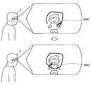
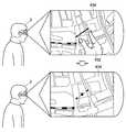
図4に示すように、ユーザの視野210内にユーザの手212が入り込んでいる場合、出力画像生成部108は、背景画像生成部106が生成した背景画像をユーザの手212に重畳させて表示する表示画像を生成する。背景画像生成部106が生成した背景画像は、ユーザの手212の後方に存在し、ユーザが目視できない背景の画像である。したがって、ユーザは、視野210では、手212によって隠れており、目視できなかった背景を表示画像が重畳された視野220では目視することができる。すなわち、出力画像生成部108は、ユーザの視野210に入り込んだユーザの手212を消去した視野220をユーザに視認させることができる。 As illustrated in FIG. 4, when the user's
以上の構成によれば、本実施形態に係る情報処理装置1は、視野内にユーザの手が入り込んだ場合に、ユーザの手により遮蔽された背景を該ユーザの手に重畳して表示させることができる。これにより、ユーザは、情報処理装置1が生成した表示画像により、視野内に入り込んだ手により隠された背景を視認することができる。よって、本実施形態に係る情報処理装置1は、視野内に入り込んだ手によってユーザの視野が制限されることを防止し、ユーザの視野を確保することができる。 According to the above configuration, the
[1.3.情報処理装置の制御]
続いて、図5を参照して、本実施形態に係る情報処理装置1の制御例について説明する。図5は、本実施形態に係る情報処理装置1が実行する制御例を示すフローチャート図である。[1.3. Control of information processing apparatus]
Next, a control example of the
図5に示すように、まず、画像取得部102は、ユーザの視野に相当する視野画像を取得する(S100)。次に、手検出部104は、画像取得部102が取得した視野画像からユーザの手を検出する(S102)。続いて、背景画像生成部106は、視野内に入り込んだ手により遮蔽され、ユーザが目視できない背景に相当する背景画像を取得する(S104)。さらに、出力画像生成部108は、視野内の手に対して背景画像を重畳して表示させる表示画像を生成する(S106)。 As shown in FIG. 5, first, the
以上の制御により、生成された表示画像がユーザの視野に重畳して表示されるため、本実施形態に係る情報処理装置1は、視野内に入り込んだユーザの手を消去した視野をユーザに視認させることができる。これにより、本実施形態に係る情報処理装置1は、ユーザの視野を確保することができる。 As a result of the above control, the generated display image is displayed so as to be superimposed on the user's field of view. Therefore, the
<2.変形例>
[2.1.情報処理装置の構成]
次に、図6〜図31Bを参照して、本開示の一実施形態の変形例に係る情報処理装置2について説明する。図6は、本変形例に係る情報処理装置2の内部構成を示したブロック図である。<2. Modification>
[2.1. Configuration of information processing apparatus]
Next, the
図6に示すように、本変形例に係る情報処理装置2は、画像取得部102と、手検出部104と、背景画像生成部106と、出力画像生成部108とを備え、さらに、視野内解析部110と、オブジェクト生成部112と、視線検出部114と、情報取得部116と、知識データベース118と、テキスト取得部120と、テキスト解析部122とを備える。 As illustrated in FIG. 6, the
なお、画像取得部102、手検出部104、背景画像生成部106、および出力画像生成部108は、<1.本開示の一実施形態>にて上述した構成と実質的に同様の構成であるため、ここでの詳細な説明は省略する。 Note that the
視野内解析部110は、視野内に入り込んだユーザの手により行われるジェスチャ動作がどのオブジェクトに対する操作を指示しているかを解析する。具体的には、視野内解析部110は、手検出部104が検出したユーザの手がどの方向にどの程度動いたかを時系列で解析し、ユーザが実行するジェスチャ動作を特定する。 The in-
また、視野内解析部110は、ユーザの手の形状からユーザが指示する地点を特定し、ユーザが指示する対象を特定する。例えば、視野内解析部110は、ユーザの手の形状が人差し指のみを伸ばし、他の指を折り曲げた形状である場合、人差し指の先端をユーザが指示する地点であると特定してもよい。また、視野内解析部110は、ユーザのジェスチャ動作から、ユーザが実行するオブジェクトに対する操作を特定する。オ例えば、ブジェクトに対する操作とは、タップ操作、ドラッグ操作、フリック操作、ピンチインアウト操作などであり、情報処理装置2は、どのジェスチャ動作がどの操作に対応するのかを予め定めておくことが好ましい。なお、視野内解析部110がユーザにより指示される対象を特定するための具体的な方法については、後述する。 Further, the in-
オブジェクト生成部112は、ユーザの視野に重畳されて表示される各種オブジェクトを生成する。具体的には、オブジェクト生成部112は、ユーザが実行するジェスチャ動作に対応してユーザのジェスチャ動作が指示する地点を示すポインタオブジェクトを生成する。また、オブジェクト生成部112は、地図、動画、各種情報などのコンテンツを表示するオブジェクトを生成する。 The
これにより、ユーザは、視野内からジェスチャ動作を実行するユーザの手が消去された場合でも、ジェスチャ動作が指示する地点をポインタオブジェクトにより確認することができる。また、オブジェクト生成部112が生成するポインタオブジェクトは、一般的にジェスチャ動作をするユーザの手よりも小さいため、ユーザは、ジェスチャ動作をする手により隠れてしまう操作対象を視認することができる。したがって、オブジェクト生成部112は、視野内の対象またはオブジェクトへの操作性を向上させることができる。 Thereby, even when the user's hand performing the gesture operation is deleted from the visual field, the user can check the point indicated by the gesture operation with the pointer object. Further, since the pointer object generated by the
なお、視野内の地点を指示するユーザの手は、静止しておらず、細かに揺れている可能性がある。そのため、オブジェクト生成部112は、ユーザが指示する地点の変化が閾値以上である場合にのみ、ポインタオブジェクトを追従して移動させ、ユーザが指示する地点の変化が閾値未満である場合、ポインタオブジェクトを移動させないようにしてもよい。これによれば、オブジェクト生成部112は、ユーザの手の細かい揺れを吸収し、ユーザが意図的に手を移動させた場合にのみ、ポインタオブジェクトを移動させることができるため、ユーザの操作感を向上させることができる。 Note that the user's hand indicating a point in the field of view is not stationary and may be slightly shaken. Therefore, the
また、オブジェクト生成部112は、ポインタオブジェクトの画像を実行する機能ごとに変更してもよい。これによれば、オブジェクト生成部112は、ジェスチャ動作によって実行される機能を生成するポインタオブジェクトの画像によってユーザに対して示すことができる。 Further, the
さらに、オブジェクト生成部112は、視野内のユーザが指示する地点と、ユーザの視線位置との距離に基づいて、ポインタオブジェクトの生成の可否を制御してもよい。具体的には、オブジェクト生成部112は、ジェスチャ動作によりユーザが指示する地点と、ユーザの視線位置とが近い場合にのみ、ポインタオブジェクトを生成してもよい。また、オブジェクト生成部112は、ジェスチャ動作によりユーザが指示する地点と、ユーザの視線位置との距離に応じて、ポインタオブジェクトの透過度を変化させてもよい。このようなユーザの視線位置に基づくポインタオブジェクトの具体的な制御は、視線検出部114の説明において後述する。 Furthermore, the
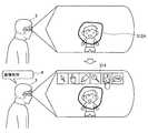
ここで、図7〜9を参照して、オブジェクト生成部112が生成するポインタオブジェクトについて、より具体的に説明する。図7は、本変形例において、出力画像生成部108が生成する表示画像の一例を示した説明図である。また、図8は、ポインタオブジェクトとしてユーザの手の一部を用いた場合の表示画像を説明する説明図であり、図9は、オブジェクト生成部112が機能別にポインタオブジェクトを生成した場合のポインタオブジェクトの例を示した説明図である。 Here, the pointer object generated by the
図7に示すように、出力画像生成部108は、ユーザの視野210内にユーザの手212が入り込んでいる場合、背景画像をユーザの手212に重畳させる表示画像を生成し、ユーザに対して、手212が消去された視野220を視認可能にする。また、オブジェクト生成部112がユーザの指示する地点を示すポインタオブジェクト232を生成している場合、出力画像生成部108は、該ポインタオブジェクト232を含む表示画像を生成し、ユーザの視野230にポインタオブジェクトを表示させる。これにより、ユーザは、視野230において、手212により指示した地点をポインタオブジェクト232にて確認することができる。 As shown in FIG. 7, when the user's
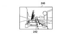
また、図8に示すように、ポインタオブジェクトは、ユーザの手の一部(すなわち、指の先端など)であってもよい。具体的には、出力画像生成部108は、ユーザの指先242以外のユーザの手212に背景画像を重畳させ、ユーザの指先242を表示した表示画像を生成してもよい。より具体的には、出力画像生成部108は、ユーザの手の形状が人差し指のみを伸ばし、他の指を折り曲げた形状である場合、人差し指の先端のみを残し、人差し指の先端以外の領域に対して背景画像を重畳させて表示する表示画像を生成してもよい。 Also, as shown in FIG. 8, the pointer object may be a part of the user's hand (ie, the tip of a finger). Specifically, the output
また、上記の方法に替えて、オブジェクト生成部112は、ユーザの手の一部(すなわち、指の先端など)の画像を用いてポインタオブジェクトを生成することで、ユーザの手の一部をポインタオブジェクトとして用いてもよい。 In addition, instead of the above method, the
この構成によれば、ユーザは、ジェスチャ動作により指示する地点を示すポインタオブジェクトが自身の指先等で表示されるため、自身が操作しているという感覚を高めることができる。これにより、情報処理装置2は、ユーザの操作感を向上させることができる。 According to this configuration, since the pointer object indicating the point designated by the gesture operation is displayed with his / her fingertip or the like, the user can increase the sense that he / she is operating. Thereby, the
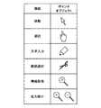
また、上述したようにオブジェクト生成部112は、ユーザがジェスチャ動作を実行した際に発揮される機能ごとに異なる画像のポインタオブジェクトを生成してもよい。例えば、オブジェクト生成部112は、機能ごとに図9に示すようなポインタオブジェクトを生成してもよい。 Further, as described above, the
例えば、図9に示すように、オブジェクト生成部112は、ポインタオブジェクトの移動に対しては、矢印形状のポインタオブジェクトを生成してもよい。また、オブジェクト生成部112は、ポインタオブジェクトによる対象の選択に対しては、手の形状のポインタオブジェクトを生成してもよい。また、オブジェクト生成部112は、ポインタオブジェクトが指示する地点への文字入力に対しては、鉛筆形状のポインタオブジェクトを生成してもよい。また、オブジェクト生成部112は、ポインタオブジェクトによる範囲選択に対しては、ハサミ形状のポインタオブジェクトを生成してもよい。また、オブジェクト生成部112は、ポインタオブジェクトが指示する対象に関する情報取得に対しては、疑問符を付した虫眼鏡形状のポインタオブジェクトを生成してもよい。さらに、オブジェクト生成部112は、ポインタオブジェクトによる拡大または縮小に対しては、プラスまたはマイナスの符号を付した虫眼鏡形状のポインタオブジェクトを生成してもよい。 For example, as illustrated in FIG. 9, the
また、オブジェクト生成部112は、ポインタオブジェクトが指示する対象がいずれかの機能を実行され得る対象である場合(例えば、選択可能な対象であったり、テキストの書き込みが可能な対象であったりする場合)、ポインタオブジェクトの画像を自動的に対応する機能を示す画像に変更してもよい。 Further, the
また、本変形例に係る情報処理装置2において、出力画像生成部108は、ユーザの複数の手が視野内に入り込んだ場合でも、同様に、背景画像をそれぞれの手に重畳させた表示画像を生成してもよい。 In the
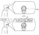
この構成について、図10および図11を参照してより具体的に説明する。図10は、ユーザの複数の手が視野内に入り込んだ場合に生成される表示画像を示す説明図である。また、図11は、ジェスチャ動作を実行していない手に対して、コンテンツオブジェクトを重畳させた表示画像を示す説明図である。 This configuration will be described more specifically with reference to FIG. 10 and FIG. FIG. 10 is an explanatory diagram showing a display image generated when a plurality of hands of the user enters the visual field. FIG. 11 is an explanatory diagram showing a display image in which a content object is superimposed on a hand that is not performing a gesture operation.
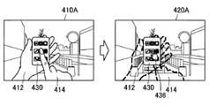
図10に示すように、視野410内にユーザの複数の手412、414が入り込んでいる場合、出力画像生成部108は、背景画像生成部106が生成した背景画像をユーザの手412、414の各々に重畳させた表示画像を生成する。ここで、上述したように、背景画像生成部106が生成した背景画像は、ユーザの手412、414の各々の背後に存在し、手412、414によりユーザが目視できない背景の画像である。これにより、ユーザは、視野410では手412、414により目視できなかった背景を、表示画像が重畳された視野420では目視することができる。 As illustrated in FIG. 10, when a plurality of user's
さらに、図11に示すように、視野410A内にジェスチャ動作を実行する一方の手414と、ジェスチャ動作を実行していない他方の手412とが入り込んだ場合、出力画像生成部108は、他方の手412に対してコンテンツオブジェクト430を重畳させた表示画像を生成してもよい。すなわち、ユーザが視認する視野420Aでは、視野410Aに入り込んだユーザの手412、414が消去され、かつ一方の手414の替わりにポインタオブジェクト436が表示され、かつ他方の手412の替わりにコンテンツオブジェクト430が表示されることになる。 Furthermore, as shown in FIG. 11, when one
この構成によれば、ユーザは、コンテンツオブジェクト430がジェスチャ動作を実行しない他方の手412に重畳されて表示されるため、より直感的にコンテンツオブジェクト430の表示の位置および表示の有無を操作することができる。なお、他方の手412に重畳されて表示されるコンテンツオブジェクト430は、ユーザが任意に選択および設定できることが好ましい。 According to this configuration, since the
また、他方の手412に重畳されて表示されたコンテンツオブジェクト430は、ユーザのピン止めなどのジェスチャ動作等により、視野内における表示位置が固定されてもよい。これによれば、コンテンツオブジェクト430を視認するために、他方の手412をユーザの視野内に入り込ませ続ける必要がなくなるため、ユーザの操作性が向上する。 The display position of the
ここで、図6に戻って本変形例に係る情報処理装置2の各構成について説明を続ける。 Here, returning to FIG. 6, the description of each component of the
視線検出部114は、ユーザの視線位置を検出する。例えば、視線検出部114は、ユーザの眼球の画像からユーザの視線の方向を検出し、ユーザが視野内のどの位置を注視しているかを検出する。上記では、ユーザが注視している視野内の位置をユーザの視線位置と表現した。なお、視線検出部114がユーザの視線位置を検出する方法は、公知の技術を用いることができるが、例えば、ユーザの眼球の画像から眼球の角膜反射像(プルキンエ像)および瞳孔重心を検出することでユーザの視線方向および視線位置を検出することができる。 The line-of-
ここで、図12を参照して、ユーザの視線位置に基づくポインタオブジェクトの画像の具体的な制御について説明する。図12は、ユーザの視線位置と、ユーザの手により指示される地点との距離に基づいたポインタオブジェクトの画像の制御を説明する説明図である。 Here, with reference to FIG. 12, the specific control of the image of the pointer object based on the user's line-of-sight position will be described. FIG. 12 is an explanatory diagram illustrating the control of the image of the pointer object based on the distance between the user's line-of-sight position and a point designated by the user's hand.
図12に示すように、ユーザの手により指示される地点(ポインタオブジェクト252A、252B、252C)の周囲には、第1領域260が設定され、第1領域の外側の周囲には、さらに第2領域262が設定される。なお、図10では、第1領域260および第2領域262の形状は、四角形状としたが、本開示はかかる例示に限定されない。例えば、第1領域260および第2領域262の形状および大きさは、任意に設定することが可能であり、例えば、円形状、楕円形状、または多角形状であってもよい。また、第1領域260および第2領域262の形状は、ユーザが自由に設定してもよい。 As shown in FIG. 12, a
まず、表示画像250Aにて示すように、ユーザの視線位置270が第1領域260の内側である場合、オブジェクト生成部112は、ポインタオブジェクト252Aを生成する。これは、ユーザの視線位置270が、ユーザの手により指示される地点(ポインタオブジェクト252A)に近い場合、ユーザが指示している地点に注意を向けている可能性が高いためである。したがって、このような場合、オブジェクト生成部112は、ポインタオブジェクト252Aを生成することで、ユーザに自身のジェスチャ動作をポインタオブジェクト252Aにて視認させることができる。 First, as illustrated in the
また、表示画像250Bにて示すように、ユーザの視線位置270が第2領域262の内側かつ第1領域260の外側である場合、オブジェクト生成部112は、ポインタオブジェクト252Bの透過度を変化させてもよい。具体的には、オブジェクト生成部112は、ユーザの視線位置270と、ユーザの手により指示される地点(ポインタオブジェクト252B)との距離が離れているほど、ポインタオブジェクト252Bの透過度を高くしてもよい。すなわち、オブジェクト生成部112は、視線位置と、ユーザの手により指示される地点(ポインタオブジェクト252B)との距離が近くなるほど、ポインタオブジェクト252Bの透過度を低くする。これによれば、オブジェクト生成部112は、透過度の変化により、ユーザに対して、ポインタオブジェクト252Bの位置を知らせることができる。 Also, as shown in the
さらに、表示画像250Cにて示すように、ユーザの視線位置270が第2領域262の外側である場合、オブジェクト生成部112は、ポインタオブジェクト252Cを生成せず、表示画像においてポインタオブジェクト252Aが表示されないようにしてもよい。これは、ユーザの視線位置270が、ユーザの手により指示される地点(ポインタオブジェクト252C)から離れている場合、ユーザが指示している地点に注意を向けていない可能性が高いためである。したがって、このような場合、オブジェクト生成部112は、ポインタオブジェクト252Cを生成しないことにより、消費電力を削減することができる。 Further, as shown in the
ここで、図6に戻って本変形例に係る情報処理装置2の各構成について説明を続ける。 Here, returning to FIG. 6, the description of each component of the
情報取得部116は、視野内解析部110により特定された対象に関する情報を知識データベース118から取得する。また、知識データベース118は、一般知識に関する情報およびユーザに関する情報などの各種情報をグラフ構造化して記憶したデータベースである。 The
本変形例に係る情報処理装置2では、情報取得部116は、ユーザのジェスチャ動作に基づいて特定された対象に関する各種情報を知識データベース118から取得する。また、情報取得部116により取得された各種情報は、オブジェクト生成部112により情報オブジェクトとして生成され、表示画像中に表示される。これにより、ユーザは、ジェスチャ動作により指示した対象に関する詳細な情報を簡便に取得し、視認することができる。 In the
以下では、図13〜図16Bを参照して、本変形例に係る情報処理装置2において、視野内解析部110が、ユーザのジェスチャ動作に基づいて、ユーザが指示する対象を特定する方法について説明する。また、図17〜図22を参照して、情報取得部116が知識データベース118から情報を取得する方法および出力画像生成部108が生成する表示画像の具体例について説明する。 Hereinafter, with reference to FIG. 13 to FIG. 16B, a description will be given of a method in which the in-
まず、図13〜図16Bを参照して、視野内解析部110がユーザ3のジェスチャ動作に基づいて対象を特定する第1〜第3の方法について説明する。図13は、視野内解析部110がユーザ3のジェスチャ動作に基づいて対象を特定する第1の方法を説明する説明図であり、図14は、視野内解析部110がユーザ3のジェスチャ動作に基づいて対象を特定する第2の方法を説明する説明図である。また、図15〜図16Bは、視野内解析部110がユーザ3のジェスチャ動作に基づいて対象を特定する第3の方法を説明する説明図である。 First, with reference to FIG. 13 to FIG. 16B, first to third methods in which the in-
図13に示すように、第1の方法とは、ユーザ3の視野内に含まれるタグ502により、ユーザ3が指示する対象を特定する方法である。例えば、映像等において、対象506に対応するタグ502が併せて表示され、ユーザ3が表示されたタグ502をジェスチャ動作にて選択した場合、視野内解析部110は、選択されたタグ502に対応する対象506をユーザ3が指示する対象として特定してもよい。なお、タグ502とは、例えば、QRコード(登録商標)、バーコード、識別IDなどである。 As shown in FIG. 13, the first method is a method of specifying a target indicated by the
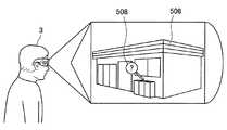
また、図14に示すように、第2の方法とは、選択範囲504に含まれる対象506を画像の特徴量などから識別することで、ユーザ3が指示する対象を特定する方法である。このような場合、視野内解析部110は、例えば、様々な物品、人物、ランドマークなどの画像の特徴量をあらかじめ機械学習によって記憶しておくことで、ユーザ3が指示した選択範囲504に含まれる対象506を識別可能にしておくことが好ましい。 As shown in FIG. 14, the second method is a method of identifying a target indicated by the
また、図15および図16Aに示すように、第3の方法とは、ユーザ3がジェスチャ動作により指示した方向情報と、ユーザ3の位置情報とから対象506の位置情報を算出し、ユーザ3が指示する対象を特定する方法である。 As shown in FIGS. 15 and 16A, the third method calculates the position information of the
具体的には、図15に示すように、まず、視野内解析部110は、視野内においてユーザ3により操作されるポインタオブジェクト508が位置する方向(すなわち、ジェスチャ動作が指示する方向)情報を取得する。次に、視野内解析部110は、ユーザ3の位置情報を取得する。ユーザ3の位置情報は、公知の方法により取得することができるが、例えば、GNSS(Global Navigation Satellite System)センサによる位置測位、Wi−Fi(登録商標)アクセスポイントまたは基地局などからの情報を用いた位置測位により取得することができる。 Specifically, as shown in FIG. 15, first, the in-
続いて、図16Aに示すように、ユーザ3の位置、およびポインタオブジェクト508が位置する方向を地図上にマッピングすることにより、視野内解析部110は、ユーザ3が指示する対象506がユーザ3を起点とする所定の方向上に存在することを特定することができる。さらに、視野内解析部110は、ユーザ3の位置を起点としてポインタオブジェクト508が位置する方向に探索範囲512を設定し、ユーザ3が指示する対象506となりうる対象を探索範囲512内にて探索する。これにより、視野内解析部110は、ユーザ3が指示する対象を特定することができる。 Subsequently, as shown in FIG. 16A, by mapping the position of the
ここで、探索範囲512は、図16Aに示すように、ユーザ3を起点としてポインタオブジェクト508が位置する方向に向いた指示方向ベクトルから所定の探索半径の円として設定されてもよい。なお、探索半径は、任意に設定することが可能であるが、例えば、以下の方法によって設定することができる。 Here, as shown in FIG. 16A, the
例えば、ジェスチャ操作の位置誤差を±0.1mとし、理想的なジェスチャ操作の位置と情報処理装置2との距離を0.3mとした場合、指示方向ベクトルと、対象506との最大誤差角は18.4°になる。したがって、18.4°の最大誤差角をカバーするように探索範囲を設定するためには、情報処理装置2と探索範囲中心との距離が30mである場合、探索半径は10mに設定することができる。 For example, when the position error of the gesture operation is ± 0.1 m and the distance between the ideal gesture operation position and the
また、探索範囲512が設定される領域は、ユーザ3から例えば、50メートルまでの領域に限定されてもよい。これは、ユーザ3から離れた対象は、ユーザにとって小さく見えるため、ユーザ3が視認している可能性が低く、また、ユーザ3が指示している可能性も低いためである。 Further, the area where the
また、図16Bに示すように、探索範囲512は、ユーザ3から離れるにつれて大きくなってもよい。これは、ユーザ3から離れた対象506は、ユーザにとって小さく見えるため、ユーザ3が対象506を正確にジェスチャ動作で指示している可能性が低くなると考えられるためである。例えば、図16Bでは、探索範囲512は、ユーザ3を起点としてポインタオブジェクト508が位置する方向に向いた扇形の領域となる。この構成によれば、視野内解析部110は、より確実に、ユーザ3が指示する対象506を含む探索範囲512を設定することができる。なお、探索範囲512がユーザ3から離れた場合の大きさの変化率は、任意に設定可能であるが、例えば、線形増加としてもよく、指数関数的な増加としてもよい。 In addition, as illustrated in FIG. 16B, the
ここで、探索範囲512内にユーザ3が指示する対象506となり得る対象が複数存在する場合、視野内解析部110は、ユーザ3を起点としてポインタオブジェクト508が位置する方向に向いた指示方向ベクトルとの距離が最も小さいものをユーザ3が指示する対象506と特定してもよい。また、視野内解析部110は、ユーザ3が指示する対象506となり得る対象をすべて列挙し、ユーザ3に列挙した中から指示する対象506を選択させてもよい。 Here, when there are a plurality of targets that can be the
なお、ユーザ3の位置情報、およびポインタオブジェクト508が位置する方向情報の精度が高い場合、ユーザ3を起点とする指示方向ベクトルとの距離が最も小さいものをユーザ3が指示する対象506とすることが好ましい。また、ユーザ3の位置情報、およびポインタオブジェクト508が位置する方向情報の精度が低い場合は、ユーザ3が指示する対象506となり得る対象をすべて列挙し、ユーザ3に列挙した中から指示する対象506を選択させることが好ましい。 If the accuracy of the position information of the
なお、視線検出部114によりユーザ3の視線位置が検出されている場合、視野内解析部110は、ユーザ3の視線方向に関する情報を取得することができる。そのため、視野内解析部110は、ポインタオブジェクト508が位置する方向に関する情報と、ユーザ3の視線方向に関する情報とを組み合わせることにより、探索範囲512を設定する方向の精度を向上させることも可能である。また、ユーザ3の視線方向と、ポインタオブジェクト508が位置する方向とが大きく異なる場合、情報処理装置2は、ユーザ3に対して、指示する対象506の方向を注視するようフィードバックしてもよい。 When the line-of-sight position of the
次に、図17〜図22を参照して、情報取得部116が特定した対象に関する情報を知識データベース118から取得する方法、および特定した対象に対して取得された情報を付与する具体例について説明する。 Next, with reference to FIG. 17 to FIG. 22, a method for acquiring information related to the target specified by the
まず、図17および図18を参照して、タグ付けされた対象へ情報を付与する具体例について説明する。図17は、「富士山」という「名前」の対象に対する情報のグラフ構造の一部を示す説明図であり、図18は、「富士山」という「名前」の対象に対して情報を付与した表示画像を説明する説明図である。 First, with reference to FIGS. 17 and 18, a specific example of giving information to a tagged target will be described. FIG. 17 is an explanatory diagram showing a part of the graph structure of the information for the “name” target “Mt. Fuji”. FIG. 18 is a display image in which information is given to the “name” target “Mt. Fuji”. It is explanatory drawing explaining these.
ここで、グラフ構造とは、各情報をノードとして、情報同士の関連性をリレーションとして表現したものである。グラフ構造の基本構造は、「subject−predicate−object」の3つ組であり、このとき、ノードは、「subject,object」であり、リレーションは、「predicate」である。 Here, the graph structure represents each information as a node and the relationship between the information as a relation. The basic structure of the graph structure is a triple of “subject-predictate-object”. At this time, the node is “subject, object”, and the relation is “predictate”.
図17に示すように、例えば、「富士山−標高−3,776m」という3つ組において、ノードは、「富士山、3,776m」であり、リレーションは、「標高」である。このような3つ組を繋げていくことにより、情報が樹形図状につながったグラフ構造を作成することができる。なお、このようなグラフ構造には、大量のノードがぶら下がる中心となるノードが存在し、このようなノードは抽象ノードと定義される。図17では、抽象ノードに対して、「名前」、「標高」、「住所」、「カテゴリ」などのリレーションを持つノードがつながっている。 As illustrated in FIG. 17, for example, in the triple “Mt. Fuji-elevation-3, 776 m”, the node is “Mt. Fuji, 3,776 m”, and the relation is “elevation”. By connecting such triplets, it is possible to create a graph structure in which information is connected in a tree diagram. In such a graph structure, there is a central node on which a large number of nodes hang, and such a node is defined as an abstract node. In FIG. 17, nodes having relations such as “name”, “elevation”, “address”, and “category” are connected to the abstract node.
ここで、図18に示すように、ユーザ3が対象506として「富士山」を視認し、「富士山」に関する情報を得るために、付与されたタグ502に対してポインタオブジェクト508を合わせて情報取得機能を実行したとする。このような場合、視野内解析部110は、タグ502のタグID「1234」を特定し、タグ502に該当する抽象ノードを特定する。次に、情報取得部116は、抽象ノードを介してグラフ構造をたどり、「富士山」の詳細情報を取得する。なお、情報取得部116が取得する詳細情報の種類および数は、任意に設定することが可能であるが、例えば、図17では、「タグID」、「コンテンツ幅」、「コンテンツ高さ」、「名前」、「標高」、「住所」、「カテゴリ」などの項目に対する詳細情報を取得している。 Here, as shown in FIG. 18, the
また、情報取得部116は、グラフ構造をたどって得られた「富士山」の詳細情報をオブジェクト生成部112に出力する。オブジェクト生成部112は、情報取得部116が取得した詳細情報に基づいて、「富士山」に関する情報を示す情報オブジェクト514を生成する。これにより、出力画像生成部108は、対象506と関連付けた配置にて情報オブジェクト514を表示する表示画像を生成することができる。 Further, the
次に、図19および図20を参照して、画像認識により識別した対象へ情報を付与する具体例について説明する。図19は、「淳也」という「名前」の対象に対する情報のグラフ構造の一部を示す説明図であり、図20は、「淳也」という「名前」の対象に対して情報を付与した表示画像を説明する説明図である。 Next, with reference to FIGS. 19 and 20, a specific example in which information is given to a target identified by image recognition will be described. FIG. 19 is an explanatory diagram showing a part of the graph structure of the information for the “name” target “Tatsuya”, and FIG. 20 is a display image in which information is given to the “name” target “Tatsuya”. It is explanatory drawing explaining these.
図19に示すように、例えば、「淳也」という「名前」の抽象ノードには、「正年」という「名前」の抽象ノードが「父」というリレーションでつながっている。また、「淳也」という「名前」の抽象ノードには、「和子」という「名前」の抽象ノードが「母」というリレーションでつながっている。このように抽象ノード同士が互いに関連性を有している場合、抽象ノード同士がつながるグラフ構造も取り得る。 As illustrated in FIG. 19, for example, an abstract node of “name” “Tatsuya” is connected to an abstract node of “name” “New Year” by a relation “father”. In addition, an abstract node of “Name” named “Tatsuya” is connected to an abstract node of “Name” named “Kazuko” by a relation “Mother”. In this way, when abstract nodes are related to each other, a graph structure in which abstract nodes are connected can also be taken.
また、「淳也」という「名前」の抽象ノードには、「スケジュール」のリレーションで「リスト」のノードがつながっている。このように、情報取得部116は、一般知識などの情報だけでなく、情報のグラフ構造をたどることによって情報処理装置2に格納させているユーザのプライバシー情報、およびスケジュール情報なども取得してもよい。 In addition, a node “list” is connected to an abstract node “name” “Tatsuya” by a relation “schedule”. As described above, the
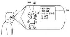
ここで、図20に示すように、ユーザ3が対象506として人物を視認し、視認した人物に関する情報を得るために、人物に対してポインタオブジェクト508を合わせて情報取得機能を実行したとする。このような場合、視野内解析部110は、画像解析により特徴量を算出し、画像に含まれる人物を識別することで、ユーザ3が情報取得機能を実行した人物に該当する抽象ノードを特定する。次に、情報取得部116は、抽象ノードを介してグラフ構造をたどり、ユーザ3が情報取得機能を実行した人物(すなわち、「名前」が「淳也」である人物)の詳細情報を取得する。例えば、図19では、「特徴量」、「名前」、「年齢」、「イベント」、「父」、「母」などの項目に対する詳細情報を取得している。 Here, as illustrated in FIG. 20, it is assumed that the
また、情報取得部116は、グラフ構造をたどって得られた人物「淳也」の詳細情報をオブジェクト生成部112に出力する。オブジェクト生成部112は、情報取得部116が取得した詳細情報に基づいて、人物「淳也」に関する情報を示す情報オブジェクト514を生成する。これにより、出力画像生成部108は、対象506と関連付けた配置にて情報オブジェクト514を表示する表示画像を生成することができる。 In addition, the
続いて、図21および図22を参照して、位置情報から識別した対象へ情報を付与する具体例について説明する。図21は、「XYZコンビニ」という「名前」の対象に対する情報のグラフ構造の一部を示す説明図であり、図22は、「XYZコンビニ」という「名前」の対象に対して情報を付与した表示画像を説明する説明図である。 Next, with reference to FIGS. 21 and 22, a specific example in which information is given to an object identified from position information will be described. FIG. 21 is an explanatory diagram showing a part of the graph structure of the information for the “name” target “XYZ convenience store”, and FIG. 22 gives information to the “name” target “XYZ convenience store”. It is explanatory drawing explaining a display image.
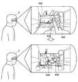
図21に示すように、例えば、「XYZコンビニ」という「名前」の抽象ノードには、「商品リスト」のリレーションで「リストA」のノードがつながっている。ユーザ3からのテキスト入力等により、「XYZコンビニ」における「商品リスト」に関する情報を取得する旨が示された場合、情報取得部116は、ユーザからのテキスト入力等に基づいて、グラフ構造をたどる方向および深さを制御してもよい。 As illustrated in FIG. 21, for example, a node “list A” is connected to an abstract node “name” “XYZ convenience store” by a relation “product list”. When the text input from the
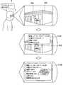
ここで、図22に示すように、ユーザ3が対象506としてコンビニエンスストアを視認し、視認したコンビニエンスストアに関する情報を得るために、コンビニエンスストアに対してポインタオブジェクト508を合わせて情報取得機能を実行したとする。このような場合、視野内解析部110は、ユーザ3の位置情報、およびポインタオブジェクト508が位置する方向情報に基づいて、対象506であるコンビニエンスストアの位置情報を特定し、対象506であるコンビニエンスストアに該当する抽象ノードを特定する。次に、情報取得部116は、抽象ノードを介してグラフ構造をたどり、ユーザ3が情報取得機能を実行したコンビニエンスストアの詳細情報を取得する。 Here, as shown in FIG. 22, the
続いて、情報取得部116は、グラフ構造をたどって得られたコンビニエンスストアの詳細情報をオブジェクト生成部112に出力する。オブジェクト生成部112は、情報取得部116が取得した詳細情報に基づいて、ユーザ3が情報取得機能を実行したコンビニエンスストアに関する情報を示す情報オブジェクトを生成する。これにより、出力画像生成部108は、対象506と関連付けた配置にて情報オブジェクト514を表示する表示画像を生成することができる。 Subsequently, the
また、ユーザ3が、情報取得機能を実行した際に、例えば、「ペペロンチーノ、あるかな?」という音声入力4を行った場合、情報取得部116は、該音声入力4に基づいて、「名前」に「ペペロンチーノ」が含まれる抽象ノードの詳細情報を取得してもよい。このような場合、情報取得部116は、グラフ構造をたどって得られた「名前」に「ペペロンチーノ」が含まれる抽象ノードの詳細情報をオブジェクト生成部112に出力する。オブジェクト生成部112は、情報取得部116が取得した詳細情報に基づいて、ユーザ3の音声入力4に応じた「ペペロンチーノ」に関する情報オブジェクト514Aを生成し、出力画像生成部108は、該情報オブジェクト514Aを表示する表示画像を生成する。 Further, when the
さらに、オブジェクト生成部112は、情報オブジェクト514A中により詳細な情報にアクセスするためのリンクを生成してもよい。具体的には、図22では、情報オブジェクト514A中の「詳細はクリック」という語句が、より詳細な情報にアクセスするためのリンクに相当する。このようなリンクをユーザ3が選択した場合、オブジェクト生成部112は、より詳細な情報を含む情報オブジェクト514Bを生成し、出力画像生成部108は、該情報オブジェクト514Bを表示する表示画像を生成し、表示させる。この構成によれば、ユーザ3は、情報取得機能の実行と併せて、テキスト入力や追加のオブジェクト操作を実行することにより、より自身の目的に沿った情報を取得することができる。 Furthermore, the
なお、上記では、情報処理装置2は、ユーザ3が対象506を指示し、情報取得機能を実行した際に情報オブジェクト514の生成および表示を実行したが、本開示に係る技術は上記例示に限定されない。例えば、情報処理装置2は、ユーザ3が情報取得機能を別途実行しなくとも、ユーザ3がジェスチャ動作によりポインタオブジェクトを対象506に重ねた際に、上述した情報オブジェクト514の生成および表示を実行してもよい。また、情報処理装置2は、ユーザ3が情報取得機能を実行した際に、ユーザ3の視野内に存在する全ての対象506について、上述した情報オブジェクト514の生成および表示を実行してもよい。 In the above description, the
また、知識データベース118に記憶される情報には、公開可否情報が設定されていてもよい。例えば、人物に関する詳細情報には、個人のプライバシーに関する情報が含まれる。そのため、誰でも他人の詳細情報を取得可能である場合、個人のプライバシーを侵害する可能性が考えられる。そこで、上述したグラフ構造において、例えば、人物に該当する抽象ノードに対して、公開可否情報として、リレーションを「公開設定」とする「公開範囲レベル」のノード(抽象ノード−公開設定−公開範囲レベル)を設定し、詳細情報の公開範囲を設定することが好ましい。 In addition, disclosure permission / prohibition information may be set in the information stored in the
上記のように、人物に該当する抽象ノードに対して、リレーションを「公開設定」とする「公開範囲レベル」のノードを設定した場合、該抽象ノードにつながる全ての詳細情報に対して、「公開範囲レベル」に対応した公開可否情報が設定されることになる。このような場合、公開可否情報が設定された人物の詳細情報は、「公開範囲レベル」によって規定されたユーザしか取得できなくなる。 As described above, when a “public range level” node whose relation is “public setting” is set for an abstract node corresponding to a person, “details” are displayed for all the detailed information connected to the abstract node. The disclosure permission / inhibition information corresponding to “range level” is set. In such a case, the detailed information of the person for whom disclosure permission / inhibition information is set can be acquired only by the user defined by the “publication range level”.
また、一部の詳細情報のみに公開可否情報を設定したい場合、例えば、一部の詳細情報のノードに対して、リレーションを「公開設定」とする「公開範囲レベル」のノードを設定することも可能である。このような場合、公開可否情報を設定した一部の詳細情報のみ「公開範囲レベル」によって規定されたユーザしか取得できなくなる。 In addition, if you want to set disclosure permission information only for some detailed information, for example, you can set a node of “Publication Level” with the relation “Public Setting” for some detailed information nodes. Is possible. In such a case, only a part of detailed information for which disclosure permission / inhibition information is set can be acquired only by a user defined by the “disclosure range level”.
ここで、公開範囲レベルの例示を図23に示す。図23は、詳細情報の公開範囲レベルの具体例を示す説明図である。図23に示すように、公開範囲レベルは、例えば、1が最も公開範囲が広く、4が最も公開範囲が狭い1〜4の4段階としてもよい。このような設定において、上位の設定は、下位の設定を包含するため、例えば、「公開範囲レベル2」に設定した詳細情報は、「公開範囲レベル2」に含まれるユーザだけでなく、「公開範囲レベル3」および「公開範囲レベル4」に含まれるユーザも取得し、参照することが可能である。なお、公開範囲レベルを「指定」に設定した詳細情報は、指定したユーザのみが取得し、参照することが可能となる。 Here, an example of the disclosure range level is shown in FIG. FIG. 23 is an explanatory diagram of a specific example of the disclosure range level of detailed information. As shown in FIG. 23, the disclosure range level may be, for example, four levels of 1 to 4 where 1 is the widest disclosure range and 4 is the narrowest disclosure range. In such a setting, since the upper setting includes the lower setting, for example, the detailed information set to “
このような詳細情報に対する公開範囲レベル等の公開可否情報の設定は、各ユーザが自身の詳細情報に対して、各自設定することが好ましい。また、各ユーザは、自身の家などの所有物の詳細情報に対して、公開可否情報を設定してもよい。 It is preferable that each user sets his / her own detailed information for setting such disclosure information such as a disclosure range level for the detailed information. In addition, each user may set the disclosure permission / inhibition information for the detailed information of the property such as his / her own house.
ここで、図6に戻って本変形例に係る情報処理装置2の各構成について説明を続ける。 Here, returning to FIG. 6, the description of each component of the
テキスト取得部120は、ユーザによって入力されたテキスト情報を取得する。具体的には、テキスト取得部120は、ユーザによって仮想キーボード等にて入力されたテキスト情報、およびユーザの音声を音声認識したテキスト情報を取得する。 The
なお、テキスト取得部120がユーザの音声を音声認識することでテキスト情報を取得する場合、テキスト取得部120は、音声認識処理を実行する前に、取得したユーザの音声に対してノイズ除去、信号増幅などの音声処理を前処理として施してもよい。 Note that when the
また、ユーザが動画等のタイムラインがあるコンテンツを視聴している場合、ユーザがコンテンツを見てから音声を発するまでにタイムラグが生じる可能性がある。そのため、テキスト取得部120は、ユーザの音声からテキスト情報を取得する場合、遅延時間を設定し、遅延時間分テキスト情報の取得のタイミングが早かったものとみなしてもよい。なお、遅延時間は、あらかじめ静的に設定された時間であってもよく、ユーザの年齢および性別等のユーザプロファイル情報に基づいて動的に設定された時間であってもよい。 In addition, when the user is viewing content with a timeline such as a moving image, there is a possibility that a time lag may occur between when the user views the content and when the user utters sound. Therefore, when acquiring text information from the user's voice, the
テキスト解析部122は、テキスト取得部120が取得したテキスト情報の意味解析を行い、知識データベース118からテキスト情報に対する応答情報を取得する。具体的には、テキスト解析部122は、表記ゆれに対応するために、テキスト取得部120が取得したテキスト情報を圧縮表記に変換する。また、テキスト解析部122は、圧縮表記に変換したテキスト情報を用いて、知識データベース118を探索し、テキスト情報に含まれる質問等への応答情報を取得する。 The
より詳細には、テキスト解析部122は、ユーザが入力したテキスト情報の記号の有無、ひらがなおよびカタカナの違い、漢字の違い、半角および全角の違い等を吸収するために、テキスト情報を統一変換ルールで変換する。ここで、統一変換ルールで変換された文字列を圧縮表記と定義する。なお、表記を一致させ、探索をより容易にするためには、知識データベース118に記憶される情報も同様に、統一変換ルールにて圧縮表記に変換されて記憶されていることが好ましい。統一変換ルールの具体例としては、例えば、括弧、記号およびスペースの削除、半角カナの全角カナへの変換、全角数字および全角英字の半角数字および半角英字への変換などが挙げられる。 More specifically, the
また、テキスト解析部122は、テキスト情報に含まれる情報の正確さが低い可能性(例えば、誤字、言い間違い、スペルミスなどが含まれる可能性)、知識データベース118に含まれる情報の有限性(例えば、知識データベース118にすべての情報が含まれているわけではないこと)等を考慮し、テキスト情報の文字列を動的に変化させ、探索に用いる文字列を増やして探索を行ってもよい。なお、テキスト解析部122が実行する探索は、情報処理量が膨大になる可能性があるため、テキスト解析部122は、探索にて取得した応答情報の数が所定数に達した段階で探索を終了させてもよい。 Further, the
さらに、テキスト解析部122は、探索にて取得した情報のスコア値を取得し、スコア値の高い情報を応答情報としてオブジェクト生成部112に出力することができる。 Furthermore, the
以下では、テキスト解析部122による知識データベース118の探索について、より具体的に説明する。 Hereinafter, the search of the
まず、テキスト解析部122は、テキスト情報の文字列を動的に変化させて、探索に用いる探索表記の候補を生成し、リスト化することで探索表記リストを生成する。次に、テキスト解析部122は、テキスト情報に含まれる言語等に基づいて、知識データベース118内において探索するデータベースを選択し、探索データベースリストを生成する。また、テキスト解析部122は、テキスト情報に含まれる語句から人、地名、および音楽などのドメインまたはジャンル等を判定可能な意味属性を取得する。 First, the
続いて、テキスト解析部122は、テキスト情報の言語、探索表記リスト、探索データベースリスト、および意味属性に基づいてデータベースを探索し、抽出ノードを決定する。次に、テキスト解析部122は、抽出ノードから同値関係子(リレーション)をたどることで、主ノード(例えば、抽象ノード)を抽出し、当該主ノードのスコア値を取得する。 Subsequently, the
また、テキスト解析部122は、各データベースの主ノードから同値関係子をたどることにより、関連ノードを抽出する。なお、関連ノードは、例えば、主ノードの略称表記、読み仮名表記、および別名表記などに相当する。次に、テキスト解析部122は、各データベースの主ノード同士の間、および主ノードと関連ノードとの間でリンクを生成し、データベース間を接続する。 In addition, the
続いて、テキスト解析部122は、設定されているヒエラルキー順に各データベースをリンクさせ、統合グラフ構造を作成する。このとき、テキスト解析部122は、ヒエラルキーが最も高いデータベースにおける主ノードをエンティティとし、各データベースの主ノードのスコア値のうち、最も値が高いものをエンティティのスコア値とする。 Subsequently, the
さらに、テキスト解析部122は、上述したエンティティを所定量生成し、各エンティティをソートして最もスコアの高いエンティティをオブジェクト生成部112に出力する。 Further, the
このような動作により、テキスト解析部122は、ユーザによって入力されたテキスト情報に含まれる質問等への応答として適切な情報を取得することができる。テキスト解析部122が取得した応答情報は、オブジェクト生成部112にて情報オブジェクトに生成され、出力画像生成部108が生成する表示画像中に表示される。 With such an operation, the
以上の構成により、本変形例に係る情報処理装置2は、ユーザに対して、ジェスチャ動作による直感的なオブジェクト操作を可能にしつつ、かつユーザの視野を確保することができる。 With the above configuration, the
[2.2.情報処理装置の制御]
続いて、図24を参照して、上述した本変形例に係る情報処理装置2の制御例について説明する。図24は、本変形例に係る情報処理装置2の各構成の制御例を説明する流れ図である。[2.2. Control of information processing apparatus]
Next, a control example of the
図24に示すように、まず、撮像装置等からの入力(S200)により、画像取得部102は、ユーザの視野に相当する視野画像を取得する(S202)。次に、手検出部104は、視野画像からユーザの手を検出し(S204)、視野内解析部110は、ユーザの手が指示する対象を特定する(S212)。このとき、必要であれば、情報取得部116は、ユーザの手が指示する対象に関する情報を知識データベース118から取得し、視野内解析部110に出力してもよい。続いて、オブジェクト生成部112は、視野内解析部110の解析に基づいて、ユーザの手が指示する対象を指示するポインタオブジェクトを生成する(S214)。 As shown in FIG. 24, first, the
また、背景画像生成部106は、手検出部104が検出したユーザの手によりユーザが目視できない背景画像を生成し(S206)、出力画像生成部108は、生成された背景画像をユーザの視野において手が占める領域に重畳させた表示画像を生成する(S208)。 Further, the background
一方、ユーザによりテキスト入力(S200)が行われた場合、テキスト取得部120は、入力されたテキストを取得する(S226)。また、ユーザにより音声による入力(S200)が行われた場合、テキスト取得部120は、音声を取得し(S220)、前処理を施した後(S222)、音声認識を行う(S224)。これにより、テキスト取得部120は、入力されたテキスト情報を取得することができる(S228)。続いて、テキスト解析部122は、知識データベース118を用いて、入力されたテキスト情報を解析する(S230)。また、テキスト解析部122は、テキスト情報に対する応答内容を生成し、オブジェクト生成部112は、生成された応答内容に基づいて、情報オブジェクトを生成する(S232)。 On the other hand, when text input (S200) is performed by the user, the
さらに、出力画像生成部108は、ユーザの手が消去された表示画像に対して、生成されたポインタオブジェクト、および情報オブジェクトを重畳し、ユーザに視認させる表示画像を生成し(S216)、表示装置に出力する(S218)。 Further, the output
本変形例に係る情報処理装置2は、以上の流れにて各構成を制御することにより、ユーザに対して、ジェスチャ動作による直感的なオブジェクト操作を可能にしつつ、かつ視野を確保することができる。 The
[2.3.情報処理装置による表示例]
以下では、図25〜図31Bを参照して、本変形例に係る情報処理装置2を用いることでユーザ3が視認可能な視野について説明する。図25〜図31Bは、本変形例に係る情報処理装置2を用いることでユーザ3が視認可能な視野を説明する説明図である。[2.3. Display example by information processing device]
Below, with reference to FIGS. 25-31B, the visual field which the
図25に示すように、ユーザ3が手302によるジェスチャ動作にて視野300内の対象を指示した場合、情報処理装置2は、手302が存在する領域に背景画像を重畳し、かつ手によって指示される地点にポインタオブジェクト304を表示した表示画像を生成する。これにより、ユーザ3が視認する視野310には、ユーザ3の手302が入り込まず、替わりにポインタオブジェクト304が表示される。そのため、ユーザは、視野300内に手302が入り込んだ場合でも、視野を確保することができる。 As shown in FIG. 25, when the
また、ユーザ3は、ジェスチャ動作により視野内の対象およびオブジェクトに対して、各種操作を行うことも可能である。例えば、図26Aに示すように、ユーザ3は、各種操作を選択可能なメニューオブジェクト306から、ポインタオブジェクト304Aにより実行する操作を選択することで、各種操作を実行することができる。このとき、選択した操作に対応してポインタオブジェクト304Bの画像は、変更されてもよい。例えば、図26Aでは、ポインタオブジェクト304Bは、テキスト入力機能を実行することを示す鉛筆の画像に変更されている。 The
なお、ユーザ3のジェスチャ動作により実行される各種操作の選択は、図26Bに示すように、ユーザ3からの音声4による入力により行われてもよい。例えば、情報処理装置2は、ユーザ3からの「文字入力」という音声4により、ポインタオブジェクト304Bをテキスト入力機能が実行可能なことを示す鉛筆の画像に変更してもよい。 Note that the selection of various operations executed by the gesture operation of the
また、ユーザ3のジェスチャ動作に実行される各種操作は、図26Cに示すように、ユーザ3の手の形状によって切り替えられてもよい。例えば、情報処理装置2は、ユーザ3が指一本伸ばした形の手302Aでジェスチャ動作した場合、対象の選択機能を実行し、ユーザ3が指二本伸ばした形の手302Bでジェスチャ動作した場合、テキスト入力機能を実行し、ユーザ3が指三本伸ばした形の手302Cでジェスチャ動作した場合、範囲選択機能を実行するように各種操作を切り換えてもよい。 Various operations executed for the gesture operation of the
また、上述したように、ジェスチャ動作により実行される機能に合わせて、ポインタオブジェクトの画像は変更されてもよい。例えば、図26Cに示すように、ポインタオブジェクトは、対象の選択機能が実行可能なことを示す手の画像304Aに変更されてもよく、テキスト入力機能が実行可能なことを示す鉛筆304Bの画像に変更されてもよく、範囲選択機能が実行可能なことを示すハサミ304Cの画像に変更されてもよい。 Further, as described above, the image of the pointer object may be changed according to the function executed by the gesture operation. For example, as shown in FIG. 26C, the pointer object may be changed to an
ここで、図27Aに示すように、ユーザ3がテキスト入力機能を用いてテキストを情報オブジェクトとして表示画像に加える場合、入力されたテキストは、ポインタオブジェクト304Bの位置を始点とする横書きの形式で表示画像に加えられてもよい。例えば、図27Aでは、ユーザ3からの音声4による入力にて、「富士山きれい」という情報オブジェクト306が表示画像に加えられている。 Here, as shown in FIG. 27A, when the
また、入力されたテキストを含む情報オブジェクト306の表示形式は、図27Aで示した横書き表示に限定されない。例えば、図27Bに示すように、ポインタオブジェクト304Bを用いたドラッグ操作が行われた場合、該ドラッグ操作が行われた領域に対して音声4の入力による「富士山きれい」という情報オブジェクト306が表示されてもよい。このような場合、情報オブジェクト306は、ユーザ3が指定する向きで表示画像に加えられることになる。 Further, the display format of the
なお、上記では、ユーザ3によるテキスト入力の方法として音声による入力方法を例示したが、テキスト入力は他の方法にて行われてもよい。例えば、図27Cに示すように、情報処理装置2は、フリック入力可能な仮想キーボード308をユーザ3の視野内に表示させ、ユーザ3に仮想キーボード308によるテキスト入力を行わせてもよい。また、情報処理装置2は、クロス型の仮想キーボード310をユーザ3の視野内に表示させ、ユーザ3に仮想キーボード310によるテキスト入力を行わせてもよい。 In the above, the voice input method is exemplified as the text input method by the
また、図28に示すように、ユーザ3は、ジェスチャ動作により、視野内の範囲を指定し、指定した範囲内の対象に対して、各種操作を行うことも可能である。例えば、図28では、ユーザ3の視野内に捉えた人物の顔を囲むようにポインタオブジェクト304Cによる範囲選択が行われている。なお、ポインタオブジェクト304Cによる範囲選択は、始点と終点とが一致した閉曲線によってなされていてもよく、始点と終点とが一致しない開曲線によってなされていてもよい。開曲線によって範囲選択がされている場合、情報処理装置2は、ユーザ3が指定した開曲線を始点と終点とを結び、閉曲線に変換することで、ユーザ3が指定した範囲を特定することができる。 As shown in FIG. 28, the
図29Aに示すように、範囲選択機能により指定した曲線312Aにて指定される範囲に対して、例えば、ユーザ3は、視認している画像の保存機能を実行することができる。また、図29Aでは、ユーザ3は、画像保存機能を実行することを音声4によって情報処理装置2に指示することも可能である。なお、ユーザ3は、メニューオブジェクト314の中から、曲線312Aにて指定される範囲に対して実行する機能を選択して情報処理装置2に指示してもよいことは言うまでもない。 As illustrated in FIG. 29A, for example, the
また、図29Bに示すように、情報処理装置2は、ユーザ3が範囲選択機能により指定した曲線を自動的に円、正方形、長方形、および正多角形などの所定の図形にフィッティングすることで補正してもよい。このような場合、ユーザ3は、ジェスチャ動作による範囲指定が正確に実行し難い場合でも、適切な範囲選択を行うことができる。なお、図29Bでは、ユーザ3は、指定した範囲に含まれる人物に関する情報取得機能を実行することを音声4によって情報処理装置2に指示している。 As shown in FIG. 29B, the
また、図30に示すように、ユーザ3の複数の手430、432が視野内に入り込む場合、例えば、情報処理装置2は、一方の手430上に地図等のコンテンツオブジェクト434を重畳して表示させ、他方の手432の先にポインタオブジェクト436を重畳して表示させてもよい。このような場合、ユーザ3は、一方の手430上に表示されたコンテンツオブジェクト434を、他方の手432で操作するポインタオブジェクト436によって操作することができる。 In addition, as illustrated in FIG. 30, when a plurality of
なお、ユーザ3が視認する視野に表示されるコンテンツオブジェクト434の拡大または縮小、およびコンテンツオブジェクト434内のコンテンツの拡大または縮小は、ユーザ3の操作により、任意に実行することが可能である。例えば、図31Aに示すように、ユーザ3はジェスチャ動作によりポインタオブジェクト436を操作し、メニューオブジェクト438内の拡大機能または縮小機能を実行することによって、コンテンツオブジェクト434の拡大または縮小を実行してもよい。また、例えば、図31Bに示すように、ユーザ3は、コンテンツオブジェクト434に対して、手432によるピンチインまたはピンチアウトのジェスチャ動作を行うことにより、コンテンツオブジェクト434内のコンテンツの拡大または縮小を実行してもよい。 The enlargement or reduction of the
以上にて、情報処理装置2により生成される表示画像が重畳されることで、ユーザ3が視認可能な視野の具体例について、詳細に説明した。 The specific example of the visual field that the
<3.ハードウェア構成>
続いて、図32を参照して、本開示の一実施形態に係る情報処理装置1のハードウェア構成について説明する。図32は、本実施形態に係る情報処理装置1のハードウェア構成の一例を示したブロック図である。なお、本実施形態に係る情報処理装置1が実行する情報処理は、ソフトウェアとハードウェアとの協働によって実現される。<3. Hardware configuration>
Next, a hardware configuration of the
図32に示すように、情報処理装置1は、例えば、CPU(Central Processing Unit)602と、ROM(Read Only Memory)604と、RAM(Random Access Memory)606と、ブリッジ610と、内部バス608および612と、インターフェース614と、入力装置616と、出力装置618と、ストレージ装置620と、ドライブ622と、接続ポート624と、通信装置626と、を備える。 As shown in FIG. 32, the
CPU602は、演算処理装置および制御装置として機能し、ROM604等に記憶されたプログラムに従って、情報処理装置1の動作全般を制御する。ROM604は、CPU602が使用するプログラムや演算パラメータを記憶し、RAM606は、CPU602の実行において使用するプログラムや、その実行において適宜変化するパラメータ等を一時記憶する。 The
これらCPU602、ROM604およびRAM606は、ブリッジ610、内部バス608および612等により相互に接続されている。また、CPU602、ROM604およびRAM606は、インターフェース614を介して入力装置616、出力装置618、ストレージ装置620、ドライブ622、接続ポート624、および通信装置626とも接続されている。 The
入力装置616は、タッチパネル、キーボード、ボタン、マイクロホン、スイッチおよびレバーなどの情報が入力される入力装置と、ユーザの入力に基づいて入力信号を生成し、CPU602に出力するための入力制御回路などから構成される。また、入力装置616は、振動センサ、加速度センサ、GNSS(Global Navigation Satellite System)センサ、地磁気センサ、気圧センサ、および温度センサなどの各種センサを含んでもよい。 The
出力装置618は、例えば、LCD(liquid crystal display)装置、OLED(organic electroluminescence display)装置およびランプなどの表示装置、ならびにスピーカおよびヘッドホンなどの音声出力装置を含む。例えば、表示装置は、生成された画像を表示し、音声出力装置は、音声データ等を音声に変換して出力する。 The
ストレージ装置620は、情報処理装置1の記憶部の一例として構成されたデータ格納用の装置である。ストレージ装置620は、記憶媒体、記憶媒体にデータを記憶する記憶装置、記憶媒体からデータを読み出す読み出し装置、および記憶されたデータを削除する削除装置を含んでもよい。 The
ドライブ622は、記憶媒体用リードライタである。ドライブ622は、ドライブ622に挿入された半導体メモリ等のリムーバブル記憶媒体に記憶されている情報を読み出して、RAM606に出力する。また、ドライブ622は、リムーバブル記憶媒体に情報を書き込むことも可能である。 The
接続ポート624は、例えば、USB(Universal Serial Bus)ポート、光オーディオ端子等のような外部接続機器を接続するための接続ポートで構成された接続インターフェースである。 The
通信装置626は、例えば、公衆回線網または専用回線網などのネットワーク7に接続するための通信デバイス等で構成された通信インターフェースである。また、通信装置626は、有線または無線LAN対応通信装置であっても、有線によるケーブル通信を行うケーブル通信装置であってもよい。 The
また、CPU、ROMおよびRAMなどのハードウェアにおいて、上述した本実施形態に係る情報処理装置1を構成する各構成と同等の機能を他の情報処理装置に発揮させるためのコンピュータプログラムも作成可能である。また、該コンピュータプログラムを記憶させた記憶媒体も提供される。 In addition, in hardware such as a CPU, ROM, and RAM, a computer program for causing other information processing apparatuses to perform the same functions as the components constituting the
<4.まとめ>
以上にて説明したように、本実施形態に係る情報処理装置によれば、視野内にユーザの手が入り込んだ場合でも、入り込んだ手に背景画像を重畳させるような表示画像を生成し、該表示画像をユーザに視認させることで、ユーザの視野を確保することが可能である。<4. Summary>
As described above, according to the information processing apparatus according to the present embodiment, even when the user's hand enters the visual field, a display image that superimposes the background image on the inserted hand is generated, By allowing the user to visually recognize the display image, the user's visual field can be secured.
また、本実施形態に係る情報処理装置によれば、ユーザは、ジェスチャ動作により直感的に視野内に表示されるオブジェクトを操作することが可能である。 Further, according to the information processing apparatus according to the present embodiment, the user can intuitively operate an object displayed in the field of view by a gesture operation.
以上、添付図面を参照しながら本開示の好適な実施形態について詳細に説明したが、本開示の技術的範囲はかかる例に限定されない。本開示の技術分野における通常の知識を有する者であれば、特許請求の範囲に記載された技術的思想の範疇内において、各種の変更例または修正例に想到し得ることは明らかであり、これらについても、当然に本開示の技術的範囲に属するものと了解される。 The preferred embodiments of the present disclosure have been described in detail above with reference to the accompanying drawings, but the technical scope of the present disclosure is not limited to such examples. It is obvious that a person having ordinary knowledge in the technical field of the present disclosure can come up with various changes or modifications within the scope of the technical idea described in the claims. Of course, it is understood that it belongs to the technical scope of the present disclosure.
例えば、上記実施形態では、情報処理装置1としてメガネ型のウェアラブル端末を例示して説明したが、本開示に係る技術は上記の例に限定されない。例えば、情報処理装置1は、ヘッドマウント型のウェアラブル端末装置であってもよく、ビデオシースルー型のウェアラブル端末装置であってもよい。これらの端末装置に対しても、本開示に係る技術を適用することが可能である。 For example, in the above-described embodiment, a glasses-type wearable terminal is illustrated and described as the
また、本明細書に記載された効果は、あくまで説明的または例示的なものであって限定的ではない。つまり、本開示に係る技術は、上記の効果とともに、または上記の効果に代えて、本明細書の記載から当業者には明らかな他の効果を奏しうる。 Further, the effects described in the present specification are merely illustrative or exemplary and are not limited. That is, the technology according to the present disclosure can exhibit other effects that are apparent to those skilled in the art from the description of the present specification in addition to or instead of the above effects.
なお、以下のような構成も本開示の技術的範囲に属する。
(1)
ユーザの視野に相当する視野画像を取得する画像取得部と、
前記視野画像の中から前記ユーザの手を検出する手検出部と、
前記視野画像に基づいて、前記手により前記ユーザが目視できない背景の背景画像を生成する背景画像生成部と、
前記ユーザの視野内の前記手が占める領域に前記背景画像を重畳させた表示画像を生成する出力画像生成部と、
を備える、情報処理装置。
(2)
前記手が指示する地点を示すポインタオブジェクトを生成するオブジェクト生成部をさらに備える、前記(1)に記載の情報処理装置。
(3)
前記オブジェクト生成部は、前記手を使ったジェスチャによって実行される機能に基づいて、生成する前記ポインタオブジェクトを変更する、前記(2)に記載の情報処理装置。
(4)
前記ユーザの視線を検出する視線検出部をさらに備え、
前記オブジェクト生成部は、前記ユーザの視線位置が前記ポインタオブジェクトの周囲に設定された所定の第1領域に含まれない場合、前記ポインタオブジェクトを生成しない
前記(2)または(3)に記載の情報処理装置。
(5)
前記オブジェクト生成部は、前記ユーザの視線位置が前記第1領域の周囲に設定された所定の第2領域に含まれる場合、前記ユーザの視線位置と前記ポインタオブジェクトとの距離に基づいて、透過度を変更した前記ポインタオブジェクトを生成する、前記(4)に記載の情報処理装置。
(6)
前記ユーザの位置情報と、前記ユーザの手により指示される方向情報とに基づく探索範囲内に存在する対象のうちから、前記ユーザが指示する対象を判断する視野内解析部をさらに備える、前記(2)〜(5)のいずれか一項に記載の情報処理装置。
(7)
前記探索範囲は、前記ユーザから離れるにつれて大きくなる、前記(6)に記載の情報処理装置。
(8)
前記ユーザの手が指示する対象に関する詳細情報を取得する情報取得部をさらに備え、
前記オブジェクト生成部は、前記対象と関連付けて前記詳細情報を表示する情報オブジェクトを生成する、前記(2)〜(7)のいずれか一項に記載の情報処理装置。
(9)
前記対象に関する詳細情報は、公開可否情報を含み、
前記情報取得部は、前記公開可否情報に基づいて、前記対象に関する詳細情報を取得する、前記(8)に記載の情報処理装置。
(10)
前記出力画像生成部は、前記ユーザの視野内の前記手が占める領域の一部に前記背景画像を重畳させた画像を生成する、前記(1)〜(9)のいずれか一項に記載の情報処理装置。
(11)
前記出力画像生成部は、少なくとも前記ユーザの視野内の前記手の一方が占める領域にコンテンツオブジェクトを重畳させた表示画像を生成する、前記(1)〜(10)のいずれか一項に記載の情報処理装置。
(12)
ユーザの視野に相当する視野画像を取得することと、
前記視野画像の中から前記ユーザの手を検出することと、
前記視野画像に基づいて、前記手により前記ユーザが目視できない背景の背景画像を生成することと、
前記ユーザの視野内の前記手が占める領域に前記背景画像を重畳させた表示画像を生成することと、
を含む情報処理方法。
(13)
コンピュータを
ユーザの視野に相当する視野画像を取得する画像取得部と、
前記視野画像の中から前記ユーザの手を検出する手検出部と、
前記視野画像に基づいて、前記手により前記ユーザが目視できない背景の背景画像を生成する背景画像生成部と、
前記ユーザの視野内の前記手が占める領域に前記背景画像を重畳させた表示画像を生成する出力画像生成部と、
として機能させるプログラム。The following configurations also belong to the technical scope of the present disclosure.
(1)
An image acquisition unit for acquiring a visual field image corresponding to the user's visual field;
A hand detection unit for detecting the user's hand from the visual field image;
Based on the field-of-view image, a background image generation unit that generates a background image of a background that is not visible to the user by the hand;
An output image generation unit that generates a display image in which the background image is superimposed on an area occupied by the hand in the field of view of the user;
An information processing apparatus comprising:
(2)
The information processing apparatus according to (1), further including an object generation unit that generates a pointer object indicating a point indicated by the hand.
(3)
The information processing apparatus according to (2), wherein the object generation unit changes the pointer object to be generated based on a function executed by a gesture using the hand.
(4)
A line-of-sight detection unit that detects the line of sight of the user;
The information according to (2) or (3), wherein the object generation unit does not generate the pointer object when the line-of-sight position of the user is not included in a predetermined first area set around the pointer object. Processing equipment.
(5)
When the user's line-of-sight position is included in a predetermined second area set around the first area, the object generation unit is based on the distance between the user's line-of-sight position and the pointer object. The information processing apparatus according to (4), wherein the pointer object that has been changed is generated.
(6)
A field-of-view analyzing unit that determines a target indicated by the user from targets existing in a search range based on the position information of the user and direction information specified by the user's hand; The information processing apparatus according to any one of 2) to (5).
(7)
The information processing apparatus according to (6), wherein the search range increases with distance from the user.
(8)
An information acquisition unit that acquires detailed information on a target indicated by the user's hand;
The information processing apparatus according to any one of (2) to (7), wherein the object generation unit generates an information object that displays the detailed information in association with the target.
(9)
Detailed information on the object includes disclosure permission / inhibition information,
The information processing apparatus according to (8), wherein the information acquisition unit acquires detailed information regarding the target based on the disclosure permission / inhibition information.
(10)
The output image generation unit according to any one of (1) to (9), wherein the output image generation unit generates an image in which the background image is superimposed on a part of a region occupied by the hand in the visual field of the user. Information processing device.
(11)
The output image generation unit according to any one of (1) to (10), wherein the output image generation unit generates a display image in which a content object is superimposed on an area occupied by at least one of the hands in the visual field of the user. Information processing device.
(12)
Obtaining a field-of-view image corresponding to the user's field of view;
Detecting the user's hand from the visual field image;
Generating a background image of a background invisible to the user by the hand based on the field-of-view image;
Generating a display image in which the background image is superimposed on an area occupied by the hand in the field of view of the user;
An information processing method including:
(13)
An image acquisition unit for acquiring a field-of-view image corresponding to a user's field of view;
A hand detection unit for detecting the user's hand from the visual field image;
Based on the field-of-view image, a background image generation unit that generates a background image of a background that is not visible to the user by the hand;
An output image generation unit that generates a display image in which the background image is superimposed on an area occupied by the hand in the field of view of the user;
Program to function as.
1、2 情報処理装置
102 画像取得部
104 手検出部
106 背景画像生成部
108 出力画像生成部
110 視野内解析部
112 オブジェクト生成部
114 視線検出部
116 情報取得部
118 知識データベース
120 テキスト取得部
122 テキスト解析部
DESCRIPTION OF
Claims (13)
Translated fromJapanese前記視野画像の中から前記ユーザの手を検出する手検出部と、
前記視野画像に基づいて、前記手により前記ユーザが目視できない背景の背景画像を生成する背景画像生成部と、
前記ユーザの視野内の前記手が占める領域に前記背景画像を重畳させた表示画像を生成する出力画像生成部と、
を備える、情報処理装置。An image acquisition unit for acquiring a visual field image corresponding to the user's visual field;
A hand detection unit for detecting the user's hand from the visual field image;
Based on the field-of-view image, a background image generation unit that generates a background image of a background that is not visible to the user by the hand;
An output image generation unit that generates a display image in which the background image is superimposed on an area occupied by the hand in the field of view of the user;
An information processing apparatus comprising:
前記オブジェクト生成部は、前記ユーザの視線位置が前記ポインタオブジェクトの周囲に設定された所定の第1領域に含まれない場合、前記ポインタオブジェクトを生成しない、請求項2に記載の情報処理装置。A line-of-sight detection unit that detects the line of sight of the user;
The information processing apparatus according to claim 2, wherein the object generation unit does not generate the pointer object when the line-of-sight position of the user is not included in a predetermined first area set around the pointer object.
前記オブジェクト生成部は、前記対象と関連付けて前記詳細情報を表示する情報オブジェクトを生成する、請求項2に記載の情報処理装置。An information acquisition unit that acquires detailed information on a target indicated by the user's hand;
The information processing apparatus according to claim 2, wherein the object generation unit generates an information object that displays the detailed information in association with the target.
前記情報取得部は、前記公開可否情報に基づいて、前記対象に関する詳細情報を取得する、請求項8に記載の情報処理装置。Detailed information on the object includes disclosure permission / inhibition information,
The information processing apparatus according to claim 8, wherein the information acquisition unit acquires detailed information about the target based on the disclosure permission / inhibition information.
前記視野画像の中から前記ユーザの手を検出することと、
前記視野画像に基づいて、前記手により前記ユーザが目視できない背景の背景画像を生成することと、
前記ユーザの視野内の前記手が占める領域に前記背景画像を重畳させた表示画像を生成することと、
を含む情報処理方法。Obtaining a field-of-view image corresponding to the user's field of view;
Detecting the user's hand from the visual field image;
Generating a background image of a background invisible to the user by the hand based on the field-of-view image;
Generating a display image in which the background image is superimposed on an area occupied by the hand in the field of view of the user;
An information processing method including:
ユーザの視野に相当する視野画像を取得する画像取得部と、
前記視野画像の中から前記ユーザの手を検出する手検出部と、
前記視野画像に基づいて、前記手により前記ユーザが目視できない背景の背景画像を生成する背景画像生成部と、
前記ユーザの視野内の前記手が占める領域に前記背景画像を重畳させた表示画像を生成する出力画像生成部と、
として機能させるプログラム。
An image acquisition unit for acquiring a field-of-view image corresponding to a user's field of view;
A hand detection unit for detecting the user's hand from the visual field image;
Based on the field-of-view image, a background image generation unit that generates a background image of a background that is not visible to the user by the hand;
An output image generation unit that generates a display image in which the background image is superimposed on an area occupied by the hand in the field of view of the user;
Program to function as.
Priority Applications (5)
| Application Number | Priority Date | Filing Date | Title |
|---|---|---|---|
| JP2015072407AJP2016192122A (en) | 2015-03-31 | 2015-03-31 | Information processing device, information processing method, and program |
| CN201680017782.7ACN107430479A (en) | 2015-03-31 | 2016-01-14 | Information processor, information processing method and program |
| US15/560,376US11182940B2 (en) | 2015-03-31 | 2016-01-14 | Information processing device, information processing method, and program |
| PCT/JP2016/051046WO2016157936A1 (en) | 2015-03-31 | 2016-01-14 | Information processing device, information processing method, and program |
| EP16771822.0AEP3279782A4 (en) | 2015-03-31 | 2016-01-14 | Information processing device, information processing method, and program |
Applications Claiming Priority (1)
| Application Number | Priority Date | Filing Date | Title |
|---|---|---|---|
| JP2015072407AJP2016192122A (en) | 2015-03-31 | 2015-03-31 | Information processing device, information processing method, and program |
Publications (1)
| Publication Number | Publication Date |
|---|---|
| JP2016192122Atrue JP2016192122A (en) | 2016-11-10 |
Family
ID=57004497
Family Applications (1)
| Application Number | Title | Priority Date | Filing Date |
|---|---|---|---|
| JP2015072407APendingJP2016192122A (en) | 2015-03-31 | 2015-03-31 | Information processing device, information processing method, and program |
Country Status (5)
| Country | Link |
|---|---|
| US (1) | US11182940B2 (en) |
| EP (1) | EP3279782A4 (en) |
| JP (1) | JP2016192122A (en) |
| CN (1) | CN107430479A (en) |
| WO (1) | WO2016157936A1 (en) |
Cited By (4)
| Publication number | Priority date | Publication date | Assignee | Title |
|---|---|---|---|---|
| JP2020046944A (en)* | 2018-09-19 | 2020-03-26 | キヤノン株式会社 | Image processing apparatus, control method, and program |
| WO2021044732A1 (en)* | 2019-09-06 | 2021-03-11 | ソニー株式会社 | Information processing device, information processing method, and storage medium |
| JP2023082098A (en)* | 2018-03-26 | 2023-06-13 | ソニーグループ株式会社 | Information processing device and information processing method |
| JP2024545002A (en)* | 2021-11-16 | 2024-12-05 | ソニー・インタラクティブエンタテインメント エルエルシー | Head-up displays in virtual reality |
Families Citing this family (12)
| Publication number | Priority date | Publication date | Assignee | Title |
|---|---|---|---|---|
| US10133532B2 (en)* | 2015-09-25 | 2018-11-20 | Seiko Epson Corporation | Display system, display device, information display method, and program |
| US11107363B2 (en)* | 2017-03-10 | 2021-08-31 | BrightMind Labs Inc. | Systems and methods for autonomous creation of personalized, self-updating curricula |
| US10254846B1 (en)* | 2017-03-15 | 2019-04-09 | Meta Company | Systems and methods to facilitate interactions with virtual content in an augmented reality environment |
| JP6874448B2 (en)* | 2017-03-17 | 2021-05-19 | 株式会社デンソーウェーブ | Information display system |
| JP7252729B2 (en)* | 2018-10-18 | 2023-04-05 | キヤノン株式会社 | Image processing device, image processing method |
| KR102637119B1 (en)* | 2018-10-25 | 2024-02-15 | 삼성전자주식회사 | Method and system for providing information regarding objects in a refrigerator |
| US10969937B2 (en)* | 2019-01-11 | 2021-04-06 | Microsoft Technology Licensing, Llc | Context-aware system menu behavior for mixed reality |
| US11799736B2 (en)* | 2019-12-27 | 2023-10-24 | Digital Guardian Llc | Systems and methods for investigating potential incidents across entities in networked environments |
| CN111659117B (en)* | 2020-07-08 | 2023-03-21 | 腾讯科技(深圳)有限公司 | Virtual object display method and device, computer equipment and storage medium |
| CN112488069B (en)* | 2020-12-21 | 2022-01-11 | 重庆紫光华山智安科技有限公司 | Target searching method, device and equipment |
| EP4033754A1 (en)* | 2021-01-21 | 2022-07-27 | Koninklijke Philips N.V. | An image synthesis system and method therefor |
| JP2023079161A (en)* | 2021-11-26 | 2023-06-07 | ソニーグループ株式会社 | Display control device, display control method, and program |
Family Cites Families (22)
| Publication number | Priority date | Publication date | Assignee | Title |
|---|---|---|---|---|
| JPH09179062A (en) | 1995-12-25 | 1997-07-11 | Canon Inc | Computer system |
| US6204828B1 (en)* | 1998-03-31 | 2001-03-20 | International Business Machines Corporation | Integrated gaze/manual cursor positioning system |
| JP3532129B2 (en)* | 1999-09-10 | 2004-05-31 | 松下電器産業株式会社 | Ultrasound diagnostic equipment |
| JP4287375B2 (en)* | 2002-09-24 | 2009-07-01 | 健爾 西 | Image display apparatus and projection optical system |
| US7084904B2 (en)* | 2002-09-30 | 2006-08-01 | Microsoft Corporation | Foveated wide-angle imaging system and method for capturing and viewing wide-angle images in real time |
| JP4456437B2 (en)* | 2004-08-06 | 2010-04-28 | 株式会社野村総合研究所 | Image processing system, image processing program, and image processing method |
| JP5104679B2 (en)* | 2008-09-11 | 2012-12-19 | ブラザー工業株式会社 | Head mounted display |
| US8228345B2 (en)* | 2008-09-24 | 2012-07-24 | International Business Machines Corporation | Hand image feedback method and system |
| US8446457B2 (en)* | 2009-11-30 | 2013-05-21 | Daniel Theobald | System for providing camera views |
| WO2011106797A1 (en) | 2010-02-28 | 2011-09-01 | Osterhout Group, Inc. | Projection triggering through an external marker in an augmented reality eyepiece |
| FR2969792B1 (en)* | 2010-12-23 | 2012-12-28 | Thales Sa | METHOD OF SUPPRESSING A COCKPIT MASK AND ASSOCIATED HELMET VISUALIZATION SYSTEM |
| US9113050B2 (en)* | 2011-01-13 | 2015-08-18 | The Boeing Company | Augmented collaboration system |
| JP5821464B2 (en)* | 2011-09-22 | 2015-11-24 | セイコーエプソン株式会社 | Head-mounted display device |
| CN103946732B (en)* | 2011-09-26 | 2019-06-14 | 微软技术许可有限责任公司 | Video based on the sensor input to perspective, near-eye display shows modification |
| US10095033B2 (en)* | 2012-07-27 | 2018-10-09 | Nokia Technologies Oy | Multimodal interaction with near-to-eye display |
| US9618747B2 (en)* | 2013-03-13 | 2017-04-11 | Jason Villmer | Head mounted display for viewing and creating a media file including omnidirectional image data and corresponding audio data |
| US9851803B2 (en)* | 2013-03-15 | 2017-12-26 | Eyecam, LLC | Autonomous computing and telecommunications head-up displays glasses |
| US9729767B2 (en)* | 2013-03-22 | 2017-08-08 | Seiko Epson Corporation | Infrared video display eyewear |
| CN103336575B (en)* | 2013-06-27 | 2016-06-29 | 深圳先进技术研究院 | The intelligent glasses system of a kind of man-machine interaction and exchange method |
| JP6237000B2 (en)* | 2013-08-29 | 2017-11-29 | セイコーエプソン株式会社 | Head-mounted display device |
| EP3044950A4 (en)* | 2013-09-12 | 2017-05-17 | Intel Corporation | Techniques for providing an augmented reality view |
| KR102209511B1 (en)* | 2014-05-12 | 2021-01-29 | 엘지전자 주식회사 | Wearable glass-type device and method of controlling the device |
- 2015
- 2015-03-31JPJP2015072407Apatent/JP2016192122A/enactivePending
- 2016
- 2016-01-14WOPCT/JP2016/051046patent/WO2016157936A1/ennot_activeCeased
- 2016-01-14EPEP16771822.0Apatent/EP3279782A4/ennot_activeWithdrawn
- 2016-01-14USUS15/560,376patent/US11182940B2/enactiveActive
- 2016-01-14CNCN201680017782.7Apatent/CN107430479A/ennot_activeWithdrawn
Cited By (6)
| Publication number | Priority date | Publication date | Assignee | Title |
|---|---|---|---|---|
| JP2023082098A (en)* | 2018-03-26 | 2023-06-13 | ソニーグループ株式会社 | Information processing device and information processing method |
| JP7438486B2 (en) | 2018-03-26 | 2024-02-27 | サターン ライセンシング エルエルシー | Information processing device, information processing method and program |
| US12184953B2 (en) | 2018-03-26 | 2024-12-31 | Saturn Licensing Llc | Information processing apparatus, information processing method, and program for presenting reproduced video including service object and adding additional image indicating the service object |
| JP2020046944A (en)* | 2018-09-19 | 2020-03-26 | キヤノン株式会社 | Image processing apparatus, control method, and program |
| WO2021044732A1 (en)* | 2019-09-06 | 2021-03-11 | ソニー株式会社 | Information processing device, information processing method, and storage medium |
| JP2024545002A (en)* | 2021-11-16 | 2024-12-05 | ソニー・インタラクティブエンタテインメント エルエルシー | Head-up displays in virtual reality |
Also Published As
| Publication number | Publication date |
|---|---|
| EP3279782A1 (en) | 2018-02-07 |
| CN107430479A (en) | 2017-12-01 |
| US20180068476A1 (en) | 2018-03-08 |
| WO2016157936A1 (en) | 2016-10-06 |
| US11182940B2 (en) | 2021-11-23 |
| EP3279782A4 (en) | 2018-11-21 |
Similar Documents
| Publication | Publication Date | Title |
|---|---|---|
| US11182940B2 (en) | Information processing device, information processing method, and program | |
| US11877203B2 (en) | Controlled exposure to location-based virtual content | |
| US12175614B2 (en) | Recording the complete physical and extended reality environments of a user | |
| US20230147019A1 (en) | Modes of control of virtual objects in 3d space | |
| US12347045B2 (en) | 3D captions with semantic graphical elements | |
| US10082940B2 (en) | Text functions in augmented reality | |
| US11381756B2 (en) | DIY effects image modification | |
| US12175613B2 (en) | 3D captions with face tracking | |
| US11948263B1 (en) | Recording the complete physical and extended reality environments of a user | |
| US8217856B1 (en) | Head-mounted display that displays a visual representation of physical interaction with an input interface located outside of the field of view | |
| KR20200121357A (en) | Object creation using physical manipulation | |
| US20170031652A1 (en) | Voice-based screen navigation apparatus and method | |
| US20230259265A1 (en) | Devices, methods, and graphical user interfaces for navigating and inputting or revising content | |
| US20150220265A1 (en) | Information processing device, information processing method, and program | |
| US20230409179A1 (en) | Home automation device control and designation | |
| WO2017218275A1 (en) | Intelligent virtual keyboards | |
| GB2549568A (en) | Search query predictions by a keyboard | |
| US20200357183A1 (en) | Methods, Systems and Apparatuses for Viewing Content in Augmented Reality or Virtual Reality | |
| JP2014186361A (en) | Information processing device, operation control method, and program | |
| US11640700B2 (en) | Methods and systems for rendering virtual objects in user-defined spatial boundary in extended reality environment | |
| US20200401212A1 (en) | Method and system of augmented-reality simulations | |
| JPWO2017104272A1 (en) | Information processing apparatus, information processing method, and program | |
| KR20180055638A (en) | Electronic device and method for controlling electronic device using speech recognition | |
| Franco | Augmented reality selection through smart glasses |