JP2016187461A - Ophthalmic equipment - Google Patents
Ophthalmic equipmentDownload PDFInfo
- Publication number
- JP2016187461A JP2016187461AJP2015068981AJP2015068981AJP2016187461AJP 2016187461 AJP2016187461 AJP 2016187461AJP 2015068981 AJP2015068981 AJP 2015068981AJP 2015068981 AJP2015068981 AJP 2015068981AJP 2016187461 AJP2016187461 AJP 2016187461A
- Authority
- JP
- Japan
- Prior art keywords
- measurement
- light
- unit
- eye
- examined
- Prior art date
- Legal status (The legal status is an assumption and is not a legal conclusion. Google has not performed a legal analysis and makes no representation as to the accuracy of the status listed.)
- Granted
Links
Images


Classifications
- A—HUMAN NECESSITIES
- A61—MEDICAL OR VETERINARY SCIENCE; HYGIENE
- A61B—DIAGNOSIS; SURGERY; IDENTIFICATION
- A61B3/00—Apparatus for testing the eyes; Instruments for examining the eyes
- A61B3/10—Objective types, i.e. instruments for examining the eyes independent of the patients' perceptions or reactions
- A61B3/103—Objective types, i.e. instruments for examining the eyes independent of the patients' perceptions or reactions for determining refraction, e.g. refractometers, skiascopes
- A—HUMAN NECESSITIES
- A61—MEDICAL OR VETERINARY SCIENCE; HYGIENE
- A61B—DIAGNOSIS; SURGERY; IDENTIFICATION
- A61B3/00—Apparatus for testing the eyes; Instruments for examining the eyes
- A61B3/10—Objective types, i.e. instruments for examining the eyes independent of the patients' perceptions or reactions
- A61B3/1005—Objective types, i.e. instruments for examining the eyes independent of the patients' perceptions or reactions for measuring distances inside the eye, e.g. thickness of the cornea
- A—HUMAN NECESSITIES
- A61—MEDICAL OR VETERINARY SCIENCE; HYGIENE
- A61B—DIAGNOSIS; SURGERY; IDENTIFICATION
- A61B3/00—Apparatus for testing the eyes; Instruments for examining the eyes
- A61B3/10—Objective types, i.e. instruments for examining the eyes independent of the patients' perceptions or reactions
- A61B3/107—Objective types, i.e. instruments for examining the eyes independent of the patients' perceptions or reactions for determining the shape or measuring the curvature of the cornea
- A—HUMAN NECESSITIES
- A61—MEDICAL OR VETERINARY SCIENCE; HYGIENE
- A61B—DIAGNOSIS; SURGERY; IDENTIFICATION
- A61B3/00—Apparatus for testing the eyes; Instruments for examining the eyes
- A61B3/0016—Operational features thereof
- A61B3/0025—Operational features thereof characterised by electronic signal processing, e.g. eye models
Landscapes
- Life Sciences & Earth Sciences (AREA)
- Health & Medical Sciences (AREA)
- Medical Informatics (AREA)
- Biophysics (AREA)
- Ophthalmology & Optometry (AREA)
- Engineering & Computer Science (AREA)
- Biomedical Technology (AREA)
- Heart & Thoracic Surgery (AREA)
- Physics & Mathematics (AREA)
- Molecular Biology (AREA)
- Surgery (AREA)
- Animal Behavior & Ethology (AREA)
- General Health & Medical Sciences (AREA)
- Public Health (AREA)
- Veterinary Medicine (AREA)
- Eye Examination Apparatus (AREA)
Abstract
Description
Translated fromJapaneseこの発明は、眼科装置に関する。 The present invention relates to an ophthalmologic apparatus.
白内障は、レンズの役目を担う水晶体が混濁することにより徐々に視力が低下していく眼疾患である。白内障が進行した被検眼に対しては、一般的に、白内障手術が行われる。たとえば、白内障手術では、混濁した水晶体を取り除き、代わりに眼内レンズ(Intraocular Lens:以下、IOL)を挿入することが行われる。IOLには、球面度のみを有するものや、乱視の矯正が可能なトーリックIOLや、遠方と近方の双方に焦点を合わせることが可能な多焦点IOLなどがある。白内障手術の前には、眼軸長などの被検眼の構造を表す眼球情報を眼科装置により測定し、測定された眼球情報からIOLの度数を決定する必要がある。 Cataract is an eye disease in which visual acuity gradually decreases due to cloudiness of the lens that serves as a lens. In general, cataract surgery is performed on an eye to be examined in which cataract has progressed. For example, in cataract surgery, a turbid lens is removed, and an intraocular lens (hereinafter referred to as IOL) is inserted instead. There are IOLs that have only sphericity, toric IOLs that can correct astigmatism, and multifocal IOLs that can focus both far and near. Prior to cataract surgery, it is necessary to measure eyeball information representing the structure of the subject's eye, such as the axial length, with an ophthalmologic apparatus and determine the frequency of the IOL from the measured eyeball information.
このような眼科装置は、たとえば、特許文献1に開示されている。特許文献1には、眼軸長を測定するための光学系と、被検眼の屈折力を測定するための光学系とを備え、被検眼の眼軸長と屈折力との測定を実行可能な眼科装置が開示されている。 Such an ophthalmologic apparatus is disclosed in
白内障を伴う被検眼においては混濁によって水晶体の透過率が低下するため、当該被検眼に照射された測定用の光が拡散され、十分な光量が眼底に到達しなかったり、眼底からの戻り光を十分に検出することができなかったりする。それにより、従来の眼科装置では、白内障が進行した被検眼に光を照射しても測定すらできず、IOLの度数を決定することができない場合があった。 In the eye to be examined with cataracts, the transmittance of the crystalline lens decreases due to turbidity, so that the measurement light irradiated to the eye to be examined is diffused, so that a sufficient amount of light does not reach the fundus or the return light from the fundus It cannot be detected sufficiently. As a result, in the conventional ophthalmic apparatus, even if light is applied to the eye to be examined where cataract has progressed, measurement cannot be performed, and the frequency of the IOL cannot be determined.
本発明は、上記の問題点を解決するためになされたものであり、白内障が進行した被検眼であってもIOLの度数を求めることが可能な眼科装置を提供することを目的とする。 The present invention has been made to solve the above-described problems, and an object thereof is to provide an ophthalmologic apparatus that can determine the frequency of IOL even in an eye to be examined in which cataract has progressed.
実施形態に係る眼科装置は、第1測定部と、第2測定部と、制御部とを含む。第1測定部は、第1光源からの光を被検眼に照射し、その戻り光を検出することにより被検眼の屈折力を測定する。第2測定部は、第2光源からの光を参照光と測定光とに分割し、測定光を被検眼に照射し、測定光の戻り光と参照光との干渉光を検出することにより被検眼の少なくとも球面度数を求める。制御部は、第1測定部による測定結果に基づいて、第2測定部に新たな測定を実行させる。 The ophthalmologic apparatus according to the embodiment includes a first measurement unit, a second measurement unit, and a control unit. The first measurement unit measures the refractive power of the subject eye by irradiating the subject eye with light from the first light source and detecting the return light. The second measurement unit divides the light from the second light source into reference light and measurement light, irradiates the eye with the measurement light, and detects interference light between the return light of the measurement light and the reference light. Obtain at least the spherical power of the optometer. A control part makes a 2nd measurement part perform a new measurement based on the measurement result by a 1st measurement part.
この発明に係る眼科装置によれば、白内障が進行した被検眼であってもIOLの度数を求めることが可能になる。 According to the ophthalmologic apparatus according to the present invention, the frequency of IOL can be obtained even for an eye to be examined in which cataract has progressed.
実施形態に係る眼科装置は、他覚測定と自覚測定とを1台で実行可能な装置である。他覚測定は、被検者からの応答を参照することなく、主として物理的な手法を用いて被検眼に関する情報を取得するものである。他覚測定には、被検眼に関する値を測定するための測定と、被検眼の画像を取得するための撮影とが含まれる。このような他覚測定には、たとえば、他覚屈折測定、角膜形状測定、眼圧測定、眼底撮影、光コヒーレンストモグラフィ(Optical Coherence Tomography:以下、OCT)の手法を用いたOCT計測などがある。自覚測定は、被検者からの応答に基づいて結果を取得するものである。自覚測定には、たとえば、遠用検査、近用検査、コントラスト検査、グレアー検査などの自覚屈折測定や、視野検査などがある。自覚測定では、被検者に情報(視標など)が呈示され、その情報に対する被検者の応答に基づいて結果が取得される。 The ophthalmologic apparatus according to the embodiment is an apparatus that can perform objective measurement and subjective measurement with a single unit. The objective measurement is to acquire information about the eye to be examined mainly using a physical method without referring to a response from the subject. The objective measurement includes measurement for measuring a value relating to the eye to be examined and photographing for obtaining an image of the eye to be examined. Examples of such objective measurement include objective refraction measurement, corneal shape measurement, intraocular pressure measurement, fundus photography, OCT measurement using optical coherence tomography (hereinafter referred to as OCT), and the like. . In the subjective measurement, a result is acquired based on a response from the subject. Examples of the subjective measurement include a subjective refraction measurement such as a distance test, a near test, a contrast test, and a glare test, and a visual field test. In subjective measurement, information (such as a visual target) is presented to a subject, and a result is acquired based on the response of the subject to the information.
この実施形態では、OCT計測においてフーリエドメインタイプのOCTの手法を用いる場合について説明する。特に、実施形態に係る眼科装置は、スペクトラルドメインOCTの手法を用いてOCT計測を行うことが可能である。なお、OCT計測は、スペクトラルドメイン以外のタイプ、たとえばスウェプトソースOCTの手法を用いてもよい。また、実施形態におけるOCT計測は、タイムドメインタイプのOCTの手法を用いることも可能である。 In this embodiment, a case where a Fourier domain type OCT technique is used in OCT measurement will be described. In particular, the ophthalmologic apparatus according to the embodiment can perform OCT measurement using a spectral domain OCT technique. The OCT measurement may use a type other than the spectral domain, for example, a swept source OCT technique. The OCT measurement in the embodiment can also use a time domain type OCT technique.
また、実施形態に係る眼科装置は、任意の自覚測定および任意の他覚測定の少なくとも一方を実行することが可能である。以下、実施形態に係る眼科装置は、自覚測定として、遠用検査、近用検査などを実行可能であり、且つ、他覚測定として、他覚屈折測定、角膜形状測定、OCT計測などを実行可能な装置であるものとする。OCT計測では、眼軸長、角膜厚、前房深度、水晶体厚などの被検眼の構造を表す眼球情報の取得が行われる。以下、OCT計測では眼球情報として眼軸長を取得する場合について説明する。なお、実施形態に係る眼科装置の構成は、以下に説明する構成に限定されるものではない。たとえば、他覚屈折測定を他の装置で行い、その測定結果の入力を受けて眼軸長測定を実行するよう構成してよい。 The ophthalmologic apparatus according to the embodiment can perform at least one of arbitrary subjective measurement and arbitrary objective measurement. Hereinafter, the ophthalmologic apparatus according to the embodiment can execute a distance test, a near-field test, and the like as the subjective measurement, and can execute an objective refraction measurement, a corneal shape measurement, an OCT measurement, and the like as the objective measurement. Device. In OCT measurement, eyeball information representing the structure of the subject's eye such as the axial length, corneal thickness, anterior chamber depth, and lens thickness is acquired. Hereinafter, the case where the axial length is acquired as the eyeball information in the OCT measurement will be described. Note that the configuration of the ophthalmic apparatus according to the embodiment is not limited to the configuration described below. For example, the objective refraction measurement may be performed by another device, and the measurement result may be received to execute the axial length measurement.
<外観構成>
図1に、実施形態に係る眼科装置の外観構成を示す。眼科装置1000は、ベース200と、架台300と、ヘッド部400と、顔受け部500と、ジョイスティック800と、表示部10とを有する。<Appearance configuration>
FIG. 1 shows an external configuration of an ophthalmologic apparatus according to the embodiment. The
架台300は、ベース200に対して前後左右に移動可能とされる。ヘッド部400は、架台300と一体的に構成されている。顔受け部500は、ベース200と一体的に構成されている。 The
顔受け部500には、顎受け600と額当て700とが設けられている。顔受け部500により被検者(図示を略す)の顔が固定される。検者は、たとえば、眼科装置1000を挟んで被検者の反対側に位置して検査を行う。ジョイスティック800および表示部10は、検者側の位置に配置されている。ジョイスティック800は、架台300上に設けられている。表示部10は、ヘッド部400の検者側の面に設けられている。表示部10は、たとえば、液晶ディスプレイなどのフラットパネルディスプレイである。表示部10は、タッチパネル式の表示画面10aを有する。 The
ヘッド部400は、ジョイスティック800の傾倒操作によって前後左右に移動される。また、ヘッド部400は、ジョイスティック800をその軸に対して回転させることにより上下方向に移動される。これら操作によって、顔受け部500に保持されている被検者の顔に対するヘッド部400の位置が変わる。なお、左右方向の移動は、たとえば、眼科装置1000による検査対象を左眼から右眼にまたは右眼から左眼に切り替えるために行われる。 The
眼科装置1000には外部装置900が接続されている。外部装置900は、任意の装置であってよく、また、眼科装置1000と外部装置900との間の接続態様(通信形態など)も任意であってよい。外部装置900は、たとえば、レンズの光学特性を測定するための眼鏡レンズ測定装置を含む。眼鏡レンズ測定装置は、被検者が装用する眼鏡レンズの度数などを測定し、この測定データを眼科装置1000に入力する。また、外部装置900は、他の任意の眼科装置であってよい。また、外部装置900は、記録媒体から情報を読み取る機能を有する装置(リーダ)や、記録媒体に情報を書き込む機能を有する装置(ライタ)であってよい。 An
外部装置900の他の例として、当該医療機関内にて使用されるコンピュータがある。このような院内コンピュータは、たとえば、病院情報システム(Hospital Information System:HIS)サーバ、DICOM(Digital Imaging and Communications in Medicine)サーバ、医師端末などを含む。外部装置900は、当該医療機関の外部にて使用されるコンピュータを含んでよい。このような院外コンピュータは、たとえば、モバイル端末、個人端末、眼科装置1000のメーカ側のサーバや端末、クラウドサーバなどがある。 Another example of the
<光学系の構成>
眼科装置1000は被検眼の検査を行うための光学系を有する。この光学系の構成例について図2〜図7を参照して説明する。光学系はヘッド部400内に設けられている。光学系は、Zアライメント投影系1と、XYアライメントスポット投影系2と、ケラト測定用リング投影系3と、固視および自覚測定系4と、観察系5と、レフ測定投影系6と、レフ測定受光系7と、眼軸長測定系8とを含む。処理部9は、各種の処理を実行する。<Configuration of optical system>
The
Zアライメント投影系1およびXYアライメントスポット投影系2は、被検眼Eに対する光学系の位置合わせ(XYZアライメント)を行うために必要な光を投影するための光学系である。Zアライメント投影系1は、観察系5の光軸に沿う方向(前後方向)のアライメントを行うための機能を有する。XYアライメントスポット投影系2は、観察系5の光軸に直交する方向(上下方向、左右方向)のアライメントを行うためのスポットを投影する機能を有する。ケラト測定用リング投影系3は、被検眼Eの角膜Kの形状を測定するための測定用リング状光束を被検眼Eに投影する機能を有する。固視および自覚測定系4は、被検眼Eに固視標および自覚測定用の視標を呈示するための光学系である。観察系5は、被検眼Eの前眼部を観察するための光学系である。レフ測定投影系6は、眼屈折力を他覚的に測定するための光束を被検眼に投影するための光学系である。レフ測定受光系7は、レフ測定投影系6により被検眼に投影された光の眼底反射光を受光するための光学系である。眼軸長測定系8は、OCT計測により被検眼Eの眼軸長を測定するための光学系である。眼軸長測定系8は、OCT光源から出力された測定光を眼底Efに投影する機能と、この測定光の戻り光を検出する機能とを有する。 The Z
(観察系5)
観察系5は、対物レンズ51と、ダイクロイックミラー52、53と、絞り54と、ハーフミラー55と、リレーレンズ56、57と、結像レンズ58と、撮像素子(CCD)59とを含む。観察系5は、更に、被検眼Eの前眼部を照明するための照明光源を含んで構成されていてもよい。撮像素子59の出力は、処理部9に入力される。処理部9は、撮像素子59から入力された信号に基づいて、表示部10に前眼部像E’を表示させる。(Observation system 5)
The
対物レンズ51と被検眼Eとの間には、ケラト板31が設けられている。ケラト板31は、角膜形状を測定するためのリング状光束を被検眼Eの角膜Kに投影するために用いられる。 A
(Zアライメント投影系1およびXYアライメントスポット投影系2)
ケラト板31の周辺にはZアライメント投影系1が設けられている。前述したように、Zアライメント投影系1は、観察系5の光軸前後方向のアライメントに用いられる。Zアライメント投影系1は、Zアライメント光源11を有する。Zアライメント光源11からの光は、角膜Kに投影される。角膜Kに投影された光は、角膜Kで反射し、結像レンズ12を経由してラインセンサー13上に投影される。角膜頂点の位置が観察系5の光軸上に対し前後方向に移動するとラインセンサー13上に投影された光束の位置が変化する。この位置の変化を解析することにより、対物レンズ51に対する被検眼Eの角膜頂点の位置を計測し、その計測値に基づいてアライメントすることができる。(Z
A Z
XYアライメントスポット投影系2は、ハーフミラー55を介して観察系5から分岐した光路を形成している。前述したように、XYアライメントスポット投影系2は、上下方向および左右方向のアライメントに用いられる。XYアライメントスポット投影系2は、XYアライメント光源21を有する。XYアライメント光源21から出力された光は、その一部がハーフミラー55にて反射されて絞り54を通過し、ダイクロイックミラー53、52を透過し、対物レンズ51を通過して被検眼Eに投影される。被検眼Eに投影された光は、角膜Kで反射され、対物レンズ51を通過して、観察系5と同じ光路を経由して撮像素子59に投影される。 The XY alignment
図2などに示すように、表示画面10aには、前眼部像E’とともに、アライメントマークALと角膜Kで反射した輝点像Brとが表示される。手動でアライメントを行う場合、ユーザは、たとえば、表示画面10aに表示されている情報を参照しつつジョイスティック800を操作してヘッド部400の位置調整を行う。このとき、処理部9は、たとえば、アライメントマークALと角膜Kで反射した輝点像Brのずれ量で上下左右方向のずれ量を算出し、表示画面10aに表示させてよい。また、Zアライメント投影系1からの処理情報を基に光軸方向のずれ量を表示画面10aに表示させてよい。処理部9は、アライメントが完了したことに対応して測定を開始するように制御を行うことができる。 As shown in FIG. 2 and the like, on the
自動でアライメントを行う場合、上述のずれ量がキャンセルされるように電動の機構を制御してヘッド部400を移動させる。この機構は、駆動力を発生するアクチュエータと、この駆動力をヘッド部400に伝達する部材とを含む。処理部9は、アライメントが完了したことに対応して測定を開始するように制御を行うことができる。 When the alignment is automatically performed, the
(固視および自覚測定系4)
固視および自覚測定系4は、光源41と、透過型の視標チャート42と、合焦レンズ43と、バリアブルクロスシリンダ(以下、VCC)レンズ44と、反射ミラー45とを含む。合焦レンズ43は、固視および自覚測定系4の光軸に沿って移動可能に構成されている。固視および自覚測定系4は、更に、ダイクロイックミラー53、52と、対物レンズ51とを含んで構成されていてもよい。(Fixation and awareness measurement system 4)
The fixation and
固視および自覚測定系4は、被検眼Eの眼底Efに視力測定用の視標を投影することが可能である。 The fixation and
光源41から出力された光(可視光)は、視標チャート42に照射される。視標チャート42は、視力測定用の視標や風景チャートなどの固視標を表示し、光源41から出力された光を透過させる。視標チャート42は、透過型の液晶パネルを含んで構成されていてもよい。この場合、液晶パネルに視力測定用の視標や固視標が表示される。視標チャート42を透過した光は、合焦レンズ43、VCCレンズ44を透過し、反射ミラー45にて反射され、ダイクロイックミラー53にて反射される。ダイクロイックミラー53にて反射された光源41からの光は、ダイクロイックミラー52を透過し、対物レンズ51を通過して、被検眼Eの眼底Efに投影される。それにより、視標チャート42に表示された視力測定用の視標や固視標が被検眼Eに呈示される。他覚屈折測定においては、眼底Efに投影された風景チャートを被検者に凝視させつつアライメントが行われ、雲霧視状態で眼屈折力が測定される。 Light (visible light) output from the
(レフ測定投影系6およびレフ測定受光系7)
レフ測定投影系6とレフ測定受光系7とによりレフ測定系が構成される。レフ測定投影系6は、レフ測定光源61から出力された光(赤外光)をリング状の測定パターン光束として被検眼Eの眼底Efに投影する機能を有する。レフ測定受光系7は、レフ測定投影系6により被検眼Eに投影された測定パターン光束の戻り光を受光する機能を有する。(Ref
The reflex
レフ測定投影系6は、レフ測定光源61と、コンデンサレンズ62と、反射ミラー63と、円錐プリズム64Aと、リレーレンズ64Bと、リング絞り64Cと、穴開きプリズム65と、ロータリープリズム66と、クイックリターンミラー67とを含む。レフ測定投影系6は、更に、ダイクロイックミラー52と、対物レンズ51とを含んで構成されていてもよい。レフ測定光源61は、レフ測定投影系6の光軸に沿って移動可能に構成される。レフ測定光源61は、被検眼Eの眼底Efと光学的に略共役な位置に配置されている。それにより、レフ測定光源61からの光が混濁した水晶体を通過し、眼底Efに到達しやすくなる。 The reflex
レフ測定受光系7は、リレーレンズ71と、合焦レンズ72と、結像レンズ73と、撮像素子(CCD)74とを含む。レフ測定受光系7は、更に、対物レンズ51と、ダイクロイックミラー52と、クイックリターンミラー67と、ロータリープリズム66と、穴開きプリズム65とを含んで構成されていてもよい。合焦レンズ72は、レフ測定受光系7の光軸に沿って移動可能に構成される。合焦レンズ72とレフ測定光源61と後述の眼軸長測定系8の合焦レンズ85とは、連係してそれぞれの光軸方向に移動される。撮像素子74の出力は、処理部9に入力される。対物レンズ51と、ダイクロイックミラー52と、クイックリターンミラー67と、ロータリープリズム66と、穴開きプリズム65とは、レフ測定投影系6と共用される。 The ref measurement
レフ測定光源61から出力された光は、コンデンサレンズ62を通過し、反射ミラー63にて反射され、円錐プリズム64A、リレーレンズ64Bを透過してリング絞り64Cに導かれる。リング絞り64Cに導かれた光は、リング状のパターン部分を通過してリング状の測定パターン光束となる。円錐プリズム64Aは、コンデンサレンズ62によって集光されたレフ測定光源61からの光をリング絞り64Cのリング状のパターン部分に集光させる。この測定パターン光束は、穴開きプリズム65の反射面にて反射され、ロータリープリズム66を通過し、クイックリターンミラー67に導かれる。ロータリープリズム66を用いることにより、眼底Efにおける血管や疾患部位への測定パターン光束の光量分布を平均化させることが可能になる。 The light output from the reflex
クイックリターンミラー67は、他覚屈折測定と眼軸長測定とを切り換えるために用いられる。他覚屈折測定を実行するとき、クイックリターンミラー67の反射面は、ダイクロイックミラー52により観察系5の光路から分岐された光路上に配置される。それにより、レフ測定投影系6の光路およびレフ測定受光系7の光路の双方は、観察系5の光路に結合される。眼軸長測定を実行するとき、クイックリターンミラー67は、ダイクロイックミラー52により観察系5の光路から分岐された光路から退避される。それにより、眼軸長測定系8の光路は、観察系5の光路に結合される。 The
ここでは、クイックリターンミラー67の反射面は、ダイクロイックミラー52により観察系5の光路から分岐された光路上に配置される。穴開きプリズム65からロータリープリズム66を通過してクイックリターンミラー67に導かれた測定パターン光束は、クイックリターンミラー67にて反射され、ダイクロイックミラー52にて反射され、対物レンズ51を通過して被検眼Eに投影される。 Here, the reflection surface of the
被検眼Eに投影された測定パターン光束の戻り光は、対物レンズ51を通過し、ダイクロイックミラー52およびクイックリターンミラー67にて反射され、ロータリープリズム66を通過し、穴開きプリズム65の中心部を通過する。穴開きプリズム65の中心部を通過した光は、リレーレンズ71、合焦レンズ72を透過し、結像レンズ73により撮像素子74の撮像面に結像される。 The return light of the measurement pattern light beam projected onto the eye E passes through the
(眼軸長測定系8)
眼軸長測定系8は、OCTユニット80と、コリメータレンズ84と、合焦レンズ85と、リレーレンズ86と、XYスキャナ87と、瞳レンズ88とを含む。眼軸長測定系8は、更に、ダイクロイックミラー52と、対物レンズ51とを含んで構成されていてもよい。ダイクロイックミラー52と、対物レンズ51とは、観察系5と共用される。(Axial length measurement system 8)
The axial
XYスキャナ87は、1次元的にまたは2次元的に光を偏向する。XYスキャナ87に対する偏向制御を行うことにより、被検眼Eに対する後述の測定光LSの入射位置を変更することができる。2次元的に光を偏向する場合、XYスキャナ87として第1方向に偏向する第1偏向部材と第2方向に偏向する第2偏向部材とを用いることが可能である。第1方向は、第2方向に略直交(交差)する方向である。XYスキャナ87に用いられる偏向部材の例として、ガルバノミラー、ポリゴンミラー、回転ミラーなどがある。また、ダボプリズム(Dove Prism)、ダブルダボプリズム(Double Dove Prism)、ローテーションプリズム(Rotation Prism)、MEMSミラースキャナーなどが用いられてもよい。XYスキャナ87は、被検眼Eの眼底Efと光学的に略共役な位置に配置されている。 The
OCTユニット80は、OCT光源81と、ファイバーカプラー82と、光路長変更ユニット90とを含む。OCTユニット80は、更に、分光器83を含んで構成されていてもよい。合焦レンズ85は、眼軸長測定系8の光軸に沿って移動可能に構成される。 The
OCT光源81から出力された光(赤外光)は、ファイバーカプラー82により測定光LSと参照光LRとに分割される。測定光LSは、OCTユニット80から出力され、光ファイバーによりコリメータレンズ84に導光される。参照光LRは、光ファイバーにより光路長変更ユニット90に導光される。光路長変更ユニット90は、参照光LRの光路長を変更する。 Light (infrared light) output from the OCT
ここでは、クイックリターンミラー67は、ダイクロイックミラー52により観察系5の光路から分岐された光路から退避される。測定光LSは、コリメータレンズ84により平行光束とされ、合焦レンズ85、リレーレンズ86を通過し、XYスキャナ87により偏向され、瞳レンズ88を通過し、ダイクロイックミラー52に導かれる。ダイクロイックミラー52に導かれたOCTユニット80からの測定光LSは、ダイクロイックミラー52にて反射され、対物レンズ51を通過して被検眼Eの眼底Efに投影される。 Here, the
眼底Efに投影された測定光の戻り光は、対物レンズ51を通過し、測定光と同じ経路でOCTユニット80に導かれる。OCTユニット80は、ファイバーカプラー82によって光路長変更ユニット90により光路長が変更された参照光と測定光の戻り光とを干渉させて干渉光LCを生成する。光路長変更ユニット90は、コリメータレンズ91と、ビームスプリッター92と、網膜用シャッター93と、網膜用参照ミラーユニット94と、角膜用シャッター95と、角膜用参照ミラーユニット96とを含む。網膜用参照ミラーユニット94は、結像レンズ94Aと、参照ミラー94Bとを含む。角膜用参照ミラーユニット96は、結像レンズ96Aと、参照ミラー96Bとを含む。ビームスプリッター92は、ファイバーカプラー82によって分割された参照光LRが導かれた参照光路を網膜測定用の参照光路と角膜測定用の参照光路とに分割する。干渉光LCは、光ファイバーにより分光器83に導光される。分光器83では、空間的に波長分離された光がラインセンサーに投影される。処理部9は、このラインセンサーから出力された信号に対し公知のFFT(Fast Fourier Transform:以下、FFT)等の信号処理を施すことにより深さ方向の情報を取り出すことができる。 The return light of the measurement light projected on the fundus oculi Ef passes through the
眼科装置1000の各部は処理部9によって制御される。処理部9は、Zアライメント光源11、XYアライメント光源21、ケラト板31のケラトリング光源32、光源41、レフ測定光源61、OCT光源81、視標チャート42、合焦レンズ43、72、85を制御する。処理部9は、更に、VCCレンズ44、クイックリターンミラー67、光路長変更ユニット90、表示部10などを制御する。 Each unit of the
(角膜形状測定機能)
ケラト測定を行う場合、処理部9は、ケラトリング光源32を点灯させる。角膜Kに投影された角膜形状測定用リング状光束の角膜による反射光束は、観察系5により撮像素子59に前眼部像とともに投影される。処理部9は、撮像素子59によって取得された像に対して所定の演算処理を施すことにより、角膜の形状を表すパラメータを算出する。(Cornea shape measurement function)
When performing kerato measurement, the
(レフ測定機能)
レフ測定(他覚屈折測定)を行う場合、処理部9は、レフ測定光源61を点灯させる。レフ測定光源61からの光は、前述のようにリング状の測定パターン光束となって被検眼Eに投影される。被検眼Eが正視(=0D(ディオプター))の場合には、レフ測定光源61と被検眼Eの眼底Efが共役となる位置がレフ測定光源61と合焦レンズ72の基準位置となっている。この状態で眼底Efに投影された光束は眼底Efで反射され、眼底Efからの戻り光に基づくリング像が撮像素子74に結像される。また、結像されたリング像から算出される測定値(屈折値)に基づき、レフ測定光源61と眼底Efが略共役となる位置にレフ測定光源61と合焦レンズ72とが移動される。処理部9は、撮像素子74により検出された眼底Efからの戻り光に基づく像を解析し、レフ測定光源61の移動量を加味することにより、被検眼Eの屈折力として球面度数S、乱視度数C、および乱視軸角度Aを求める。(Ref measurement function)
When performing the reflex measurement (objective refraction measurement), the
レフ測定光源61は、たとえばSLD(Super Luminescent Diode)のような広帯域の低コヒーレンス光を出力する。レフ測定光源61は、たとえば、中心波長が820nm〜880nmの範囲に含まれる低コヒーレンス光源である。これにより、測定光が視認されることによる被検者の負担を軽減しつつ、他覚屈折測定が可能になる。 The reflex
(眼軸長測定機能)
眼軸長測定は、OCT計測機能を用いて実行される。眼軸長測定を実行する場合、処理部9は、光路長変更ユニット90を制御しつつ被検眼Eの角膜頂点から網膜までの距離を眼軸長として測定する。まず、処理部9は、OCT光源81を点灯させる。OCT光源81の点灯に同期して、光路長変更ユニット90が制御される。具体的には、角膜用シャッター95がビームスプリッター92と角膜用参照ミラーユニット96との間の光路に挿入され、網膜用シャッター93がビームスプリッター92と網膜用参照ミラーユニット94との間の光路から退避される。OCT光源81からの光L0は、ファイバーカプラー82により測定光LSと参照光LRとに分割される。測定光LSは、上記のように被検眼Eの眼底Efに投影される。このとき、クイックリターンミラー67は、光路外に退避されている。また、前述の被検眼Eの屈折力測定結果より、ファイバー80aの端面は被検眼Eの眼底Efと共役となるように合焦レンズ85が移動されている。眼底Efで反射された光は同光路を戻りファイバー端面に投影され、ファイバーカプラー82に到達する。(Axial length measurement function)
The axial length measurement is performed using the OCT measurement function. When performing the axial length measurement, the
一方、参照光LRは、コリメータレンズ91により平行光となり、50:50のビームスプリッター92により2つの光束(角膜用、網膜用)に分割される。ビームスプリッター92により分割された網膜用の光束は、結像レンズ94Aにより参照ミラー(反射ミラー)94Bに集光される。ビームスプリッター92により分割された角膜用の光束は、結像レンズ96Aにより参照ミラー(反射ミラー)96Bに集光される。ここで、前述のように、角膜用シャッター95が光路に挿入され、且つ、網膜用シャッター93が光路から退避されているので、参照ミラー94Bから反射した光のみが、同光路を戻りファイバーカプラー82に到達する。眼底Efおよび参照ミラー94Bで反射した光は、ファイバーカプラー82で合波され干渉信号(干渉光LC)として、分光器83に導かれる。分光器83では、空間的に波長分離された光がラインセンサーに投影される。処理部9は、このラインセンサーから出力された信号に対し公知のFFT等の信号処理を施すことにより深さ方向の情報を取り出すことができる。 On the other hand, the reference light LR becomes parallel light by the
網膜用参照ミラーユニット94と角膜用参照ミラーユニット96とは、被検眼Eの眼軸長に合わせて、干渉信号の位置が深さ方向で所定位置となるように移動される。たとえば、深さ方向に対するFFT後の干渉信号の強度変化を図5のように表す。この場合、図4に示すように網膜用参照ミラーユニット94を光軸方向に移動させることにより、図5に示すように所定範囲内の所定位置となるように網膜による干渉信号SC0の位置を移動することができる。ここで、参照ミラー96Bの位置については、固定されていてもよい。 The retina
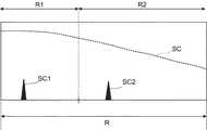
更に、前述のZアライメント投影系1を用いて角膜頂点座標が検出されるため、角膜頂点と対物レンズ51の距離(作動距離)を常に一定距離内に合わせることが可能となる。ここで、角膜用シャッター95が光路から退避されると、被検眼Eに投影された光のうち、被検眼Eの角膜Kで反射した光との干渉信号が分光器83に同時に投影される。作動距離が所定範囲内である場合、参照ミラー96Bは、網膜による干渉信号SC1と重ならないように角膜位置とは距離dだけ離れた位置になるように配置されている(図6)。したがって、図7(図5と同様に深さ方向に対するFFT後の干渉信号の強度変化を表す)に示すように、干渉信号計測範囲R内で、同時に2つの干渉信号(網膜による干渉信号SC1および角膜による干渉信号SC2)を取得することが可能となる。特に、図7に示すように信号感度SCが変化する場合、信号成分の弱い網膜による干渉信号SC1を信号感度の高い計測範囲R1で検出し、信号成分の強い角膜による干渉信号SC2を信号感度の弱い計測範囲R2で検出する。それにより、2つの干渉信号を高精度に同時に取得することができる。 Furthermore, since the corneal vertex coordinates are detected using the above-described Z
なお、OCTユニット80がスウェプトソースタイプのOCT装置と同様の構成を有する場合、低コヒーレンス光を出力するOCT光源81の代わりに波長掃引光源が設けられるとともに、干渉光をスペクトル分解する光学部材が設けられない。OCTユニット80の構成については、OCTのタイプに応じた公知の技術を任意に適用することができる。 When the
OCT光源81は、たとえばSLDのような広帯域の低コヒーレンス光L0を出力する。OCT光源81は、たとえば、中心波長が820nm〜880nmまたは1040〜1060nmの範囲に含まれる低コヒーレンス光源である。これにより、測定光が視認されることによる被検者の負担を軽減しつつ、OCT計測が可能になる。 The OCT
なお、コリメータレンズ91と参照ミラー94B、96Bとの間の参照光LRの光路に、ガラスブロックや濃度フィルターが配置されていてもよい。ガラスブロックや濃度フィルターは、参照光LRと測定光LSの光路長(光学距離)を合わせるための遅延手段として作用する。また、ガラスブロックや濃度フィルターは、参照光LRと測定光LSの分散特性や網膜用参照ミラーユニット94と角膜用参照ミラーユニット96との分散特性を合わせるための手段として作用する。 A glass block or a density filter may be disposed in the optical path of the reference light LR between the
分光器83は、たとえば、コリメータレンズ、回折格子、結像レンズ、CCDを含んで構成される。分光器83に入射した干渉光LCは、コリメータレンズにより平行光束とされた後、回折格子によって分光(スペクトル分解)される。分光された干渉光LCは、結像レンズによってCCDの撮像面上に結像される。CCDは、この干渉光LCを受光して電気的な検出信号に変換し、この検出信号を処理部9に出力する。処理部9は、CCDからの検出信号に基づいて、被検眼Eの断層のOCT情報(たとえば、画像データなど)を生成する。この処理には、従来のスペクトラルドメインタイプのOCTと同様に、ノイズ除去(ノイズ低減)、フィルター処理、FFTなどの処理が含まれている。 The
また、OCTユニット80がスウェプトソースタイプのOCT装置と同様の構成を有する場合、分光器83は、たとえば、光分岐器と、バランスドフォトダイオード(Balanced Photo Diode:BPD)とを含んで構成される。分光器83に入射した干渉光LCは、光分岐器により分割され、一対の干渉光に変換される。BPDは、一対の干渉光をそれぞれ検出する一対のフォトディテクタを有し、これらによる検出信号(検出結果)の差分を処理部9に出力する。 When the
なお、この実施形態ではマイケルソン型の干渉計を採用したが、たとえばマッハツェンダー型など任意のタイプの干渉計を適宜採用することが可能である。 In this embodiment, a Michelson interferometer is used. However, for example, any type of interferometer such as a Mach-Zehnder type can be appropriately used.
(自覚測定機能)
自覚測定を行う場合、処理部9は視標チャート42を制御し、所望の視標を表示させる。また、処理部9は、他覚測定の結果に応じた位置に合焦レンズ43を移動させる。同様に、処理部9は、他覚測定で得られた被検眼Eの乱視状態(乱視度数、乱視軸角度)に基づいて、この乱視状態が矯正されるようにVCCレンズ44を制御することが可能である。乱視度数は、VCCレンズ44を構成する2つのシリンダレンズを独立に互いに逆方向に回転させることにより変更可能である。乱視軸角度は、VCCレンズ44を構成する2つのシリンダレンズを同方向に同じ角度だけ回転させることにより変更可能である。(Awareness measurement function)
When performing subjective measurement, the
検者または処理部9により視標が選択されると、処理部9は、視標チャート42を制御し、所望の視標を表示させる。この視標からの光は、合焦レンズ43、VCCレンズ44、反射ミラー45、ダイクロイックミラー53および52、対物レンズ51を経由して眼底Efに投影される。 When the examiner or the
被検者は、眼底Efに投影された視標に対する応答を行う。たとえば、視力測定用の視標の場合には、被検者の応答により被検眼の視力値が決定される。たとえば、乱視検査の場合には、ドットチャートが駆動、表示され、被検者の応答により被検眼の乱視度数が決定される。視標の選択とそれに対する被検者の応答が、検者または処理部9の判断により繰り返し行われる。検者または処理部9は、被検者からの応答に基づいて視力値或いは処方値(S、C、A)を決定する。 The subject responds to the visual target projected onto the fundus oculi Ef. For example, in the case of a visual target for visual acuity measurement, the visual acuity value of the eye to be examined is determined by the response of the subject. For example, in the case of astigmatism examination, a dot chart is driven and displayed, and the astigmatism power of the eye to be examined is determined by the response of the subject. The selection of the target and the response of the subject to the selection are repeatedly performed based on the judgment of the examiner or the
固視および自覚測定系4の構成、Zアライメント投影系1およびXYアライメントスポット投影系2の構成、ケラト系の構成、眼屈折力(レフ)の測定原理、自覚測定の測定原理、角膜形状の測定原理などは公知である。したがって、この実施形態では、これらについての詳細な説明は省略する。 Structure of fixation and
(情報処理系の構成)
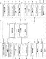
眼科装置1000の情報処理系について説明する。眼科装置1000の情報処理系の機能的構成の例を図8および図9に示す。情報処理系は、制御部110と、演算処理部120と、表示部170と、操作部180と、通信部190とを含む。制御部110は、演算処理部120、Zアライメント投影系1、XYアライメントスポット投影系2、ケラト測定用リング投影系3、固視および自覚測定系4、観察系5、レフ測定投影系6、レフ測定受光系7、眼軸長測定系8を制御する。また、制御部110は、表示部170および通信部190を制御する。Zアライメント投影系1に対する制御として、Zアライメント光源11に対する制御や、ラインセンサー13に対する制御などがある。XYアライメントスポット投影系2に対する制御として、XYアライメント光源21に対する制御などがある。ケラト測定用リング投影系3に対する制御として、ケラトリング光源32に対する制御などがある。処理部9は、たとえば、制御部110と、演算処理部120とを含んで構成される。(Information processing system configuration)
The information processing system of the
(制御部110)
制御部110は、主制御部111と、記憶部112とを有する。制御部110は、たとえば、マイクロプロセッサ、RAM(Random Access Memory)、ROM(Read Only Memory)、ハードディスクドライブ等を含んで構成される。(Control unit 110)
The
(主制御部111)
主制御部111は、眼科装置1000の各種制御を行う。主制御部111は、Zアライメント投影系1のZアライメント光源11やラインセンサー13、XYアライメントスポット投影系2のXYアライメント光源21、ケラト測定用リング投影系3のケラトリング光源32を制御する。それにより、Zアライメント光源11やXYアライメント光源21やケラトリング光源32から出力される光の光量が変更されたり、点灯や非点灯が切り換えられたりする。また、ラインセンサー13により検出された信号が取り込まれ、取り込まれた信号に基づくアライメント制御等が行われる。(Main control unit 111)
The
主制御部111は、固視および自覚測定系4の光源41、視標チャート42、合焦レンズ43、VCCレンズ44を制御する。それにより、光源41から出力される光の光量が変更されたり、点灯や非点灯が切り換えられたり、視標チャート42に視標や固視標が表示されたり、合焦レンズ43の光軸方向の位置が変更されたりする。また、VCCレンズ44により被検眼Eの乱視状態が矯正されたりする。 The
主制御部111は、観察系5の撮像素子59を制御する。それにより、撮像素子59により取得された信号が取り込まれ、演算処理部120により画像の形成等が行われたりする。なお、観察系5が照明光源を含んで構成されている場合、主制御部111は照明光源を制御することが可能である。 The
主制御部111は、レフ測定投影系6のレフ測定光源61、ロータリープリズム66、クイックリターンミラー67を制御する。それにより、レフ測定光源61がレフ測定投影系6の光軸に沿って移動されたり、レフ測定光源61から出力される光の光量が変更されたり、点灯や非点灯が切り換えられたりする。また、ロータリープリズム66が回転されたり、クイックリターンミラー67により光路が切り換えられたりする。 The
主制御部111は、レフ測定受光系7の合焦レンズ72や撮像素子74を制御する。それにより、合焦レンズ72の光軸方向の位置が変更されたり、撮像素子74により取得された信号が取り込まれ、演算処理部120により画像の形成等が行われたりする。 The
主制御部111は、レフ測定光源61から出力される光の光量、撮像素子74の検出感度、露光時間、および撮像素子74により検出された光に基づく像の重ね合わせ枚数のうち少なくとも1つを変更することが可能である。それにより、レフ測定投影系6およびレフ測定受光系7を用いる測定の条件が変更される。 The
主制御部111は、眼軸長測定系8のOCT光源81、分光器83、合焦レンズ85、XYスキャナ87、網膜用シャッター93、角膜用シャッター95、網膜用参照ミラーユニット94、および角膜用参照ミラーユニット96を制御する。それにより、OCT光源81から出力される光の光量が変更されたり、点灯や非点灯が切り換えられたり、分光器83により取得された信号が取り込まれ、演算処理部120により画像の形成等が行われたり、合焦レンズ85の光軸方向の位置が変更されたりする。また、被検眼Eに対する測定光LSの入射位置が変更されたり、参照ミラーの位置が変更されたりする。主制御部111は、合焦レンズ85をレフ測定光源61および合焦レンズ72に連動して眼軸長測定系8の光軸に沿って移動させてもよい。また、主制御部111は、更に合焦レンズ85に連動して合焦レンズ43を光軸に沿って移動させてもよい。 The
主制御部111は、OCT光源81から出力される光の光量、分光器83の検出感度、露光時間、および分光器83により検出された光に基づく像の重ね合わせ枚数のうち少なくとも1つを変更することが可能である。それにより、眼軸長測定系8を用いる測定の条件が変更される。 The
また、主制御部111は、記憶部112にデータを書き込む処理や、記憶部112からデータを読み出す処理を行う。 Further, the
(記憶部112)
記憶部112は、各種のデータを記憶する。記憶部112に記憶されるデータとしては、たとえば、OCT情報の画像データ、眼底像の画像データ、被検眼情報などがある。被検眼情報は、患者IDや氏名などの被検者に関する情報や、左眼/右眼の識別情報などの被検眼に関する情報を含む。測定情報は、眼科装置1000の内部または外部にて被検眼Eの眼屈折力測定が行われたときに記憶部112に記憶される。また、記憶部112には、眼科装置1000を動作させるための各種プログラムやデータが記憶されている。(Storage unit 112)
The
(表示部170、操作部180)
表示部170は、制御部110による制御を受けて情報を表示する。表示部170は、図1などに示す表示部10を含む。(Display unit 170, operation unit 180)
The display unit 170 displays information under the control of the
操作部180は、眼科装置1000を操作するために使用される。操作部180は、眼科装置1000に設けられた各種のハードウェアキー(ジョイスティック800、ボタン、スイッチなど)を含む。また、操作部180は、タッチパネル式の表示画面10aに表示される各種のソフトウェアキー(ボタン、アイコン、メニューなど)を含む。 The
表示部170および操作部180の少なくとも一部が一体的に構成されていてもよい。その典型例として、タッチパネル式の表示画面10aがある。 At least a part of the display unit 170 and the
(通信部190)
通信部190は、図1に示す外部装置900と通信するための機能を有する。通信部190は、たとえば処理部9に設けられていてもよい。通信部190は、外部装置900との通信の形態に応じた構成を有する。(Communication unit 190)
The
(演算処理部120)
演算処理部120は、図9に示すように、眼屈折力算出部121と、眼軸長算出部122と、IOL度数算出部123とを含む。眼屈折力算出部121は、第1屈折力算出部121Aと、第2屈折力算出部121Bとを含む。また、演算処理部120は、ラインセンサー13や撮像素子59、74や分光器83により取得された信号を取り込み、各種の制御や画像の形成や解析等を行う。(Operation processing unit 120)
As shown in FIG. 9, the
眼屈折力算出部121は、被検眼Eの屈折力を算出する。眼屈折力算出部121は、レフ測定投影系6およびレフ測定受光系7を用いた屈折力測定において被検眼Eの屈折力を求めたり、眼軸長測定系8を用いた屈折力測定において被検眼Eの屈折力を求めたりする。主制御部111は、レフ測定投影系6およびレフ測定受光系7を用いた屈折力測定の測定結果に基づいて、眼軸長測定系8を用いて被検眼Eの屈折力測定を実行させることが可能である。レフ測定投影系6およびレフ測定受光系7を用いて屈折力測定が行われたとき、第1屈折力算出部121Aにより被検眼Eの屈折力が求められる。眼軸長測定系8を用いて屈折力測定が行われたとき、第2屈折力算出部121Bにより被検眼Eの屈折力が求められる。 The eye refractive
第1屈折力算出部121Aは、被検眼Eに投影されたリング状の測定パターン光束の眼底Efからの戻り光に基づくリング像の形状を解析することにより被検眼Eの眼球光学系の屈折力を算出する。第1屈折力算出部121Aは、たとえば、戻り光に基づくリング像が描出された画像を解析し、リング像の重心位置を求める。第1屈折力算出部121Aは、画像内の画素値(輝度値)の分布を求めることによりリング像の重心に位置を求めることが可能である。次に、第1屈折力算出部121Aは、求められた重心位置を中心にリング像の外周方向に延びる複数の走査方向について画素値(輝度値)を走査し、各走査方向の輝度分布を求める。第1屈折力算出部121Aは、各走査方向の輝度分布から所定の輝度値の範囲内の中心位置を求めることによりリング像を特定し、特定されたリング像に対して楕円近似処理を行うことにより近似楕円を特定する。第1屈折力算出部121Aは、特定された近似楕円の長径の長さと短径の長さとを用いた公知の式にしたがって、球面度数S、乱視度数C、および乱視軸角度Aを求める。また、第1屈折力算出部121Aは、撮像素子74によって取得されたリング像の基準パターンからの変形や変位を求め、求められた変形や変位から被検眼Eの屈折力を求めることが可能である。 The first refractive
第2屈折力算出部121Bは、眼軸長測定系8を用いたOCT計測により被検眼Eの少なくとも球面度数を求める。この実施形態では、第2屈折力算出部121Bは、球面度数として等価球面度数を求めることが可能である。第2屈折力算出部121Bは、OCT計測において参照ミラー(たとえば、参照ミラー94B)を移動させることにより干渉光LCの検出信号のピーク値を探索してピーク位置を特定する。第2屈折力算出部121Bは、0Dの基準位置からの参照ミラーの移動量と、特定されたピーク位置の基準位置からのずれ量とに基づいて等価球面度数を求める。 The second refractive power calculation unit 121B obtains at least the spherical power of the eye E by OCT measurement using the axial
また、眼屈折力算出部121は、観察系5の撮像素子59によって取得されたケラトリング像を解析することにより、角膜屈折力や角膜乱視度や角膜乱視軸角度を算出することが可能である。たとえば、眼屈折力算出部121は、取得されたケラトリング像に対して演算処理を施すことにより角膜前面の強主経線や弱主経線の角膜曲率半径を算出し、算出された角膜曲率半径から角膜屈折力や角膜乱視度や角膜乱視軸角度を算出する。 The eye refractive
眼軸長算出部122は、眼軸長測定系8を用いて取得された図7に示す2つの干渉信号を用いて被検眼Eの眼軸長を算出する。 The axial
IOL度数算出部123は、被検眼Eの眼屈折力と眼軸長とを用いて、公知の計算式によりIOLの度数を求める。なお、IOL度数算出部123は、眼屈折力や眼軸長以外の眼球情報を用いて、IOLの度数を求めてもよい。このような眼球情報として、角膜厚、前房深度、水晶体厚などがある。 The IOL
レフ測定投影系6、レフ測定受光系7、および演算処理部120(第1屈折力算出部121A)は、この実施形態に係る「第1測定部」の一例である。レフ測定投影系6およびレフ測定受光系7は、この実施形態に係る「測定光学系」の一例である。撮像素子74は、この実施形態に係る「第1検出部」の一例である。眼軸長測定系8および演算処理部120(第2屈折力算出部121B)は、この実施形態に係る「第2測定部」の一例である。OCTユニット80は、この実施形態に係る「干渉光学系」の一例である。分光器83は、この実施形態に係る「第2検出部」の一例である。 The reflex
<動作例>
実施形態に係る眼科装置1000の動作例について説明する。この実施形態では、被検眼Eに対する他覚屈折測定により得られた測定結果を用いてIOL度数を決定することができない場合に、眼軸長測定系8を用いたOCT計測により被検眼Eの少なくとも球面度数を求める。以下では、IOL度数を決定することができない場合として、被検眼Eに対して投影されたリング状の測定パターン光束の戻り光に基づくリング像を取得することができないと判断された場合を例に説明するが、実施形態はこれに限定されるものではない。<Operation example>
An operation example of the
図10〜図12に、この実施形態に係る眼科装置1000の動作例のフロー図を示す。 10 to 12 are flowcharts showing an operation example of the
(S1)
まず、被検者の顔を顔受け部500で固定した後、操作部180に対する検者の操作を受け、制御部110は、Zアライメント光源11やXYアライメント光源21や光源41を点灯させる。処理部9は、撮像素子59の撮像面上に結像された前眼部像の撮像信号を取得し、表示部170(表示部10の表示画面10a)に前眼部像E’を表示させる。その後、ヘッド部400が被検眼Eの検査位置に移動される。検査位置とは、被検眼Eの検査を行うことが可能な位置である。前述のアライメント(Zアライメント投影系1およびXYアライメントスポット投影系2と観察系5とによるアライメント)を介して被検眼Eが検査位置に配置される。ヘッド部400の移動は、ユーザによる操作若しくは指示または制御部110による指示にしたがって、制御部110によって実行される。すなわち、被検眼Eの検査位置へのヘッド部400の移動と、他覚測定を行うための準備とが行われる。(S1)
First, after the subject's face is fixed by the
また、制御部110は、レフ測定光源61と合焦レンズ72、合焦レンズ85、合焦レンズ43が連動して、光軸に沿って原点、たとえば、0Dの位置に移動される。原点への移動は、ユーザによる操作若しくは指示または制御部110による指示にしたがって、制御部110によって実行される。ユーザによってフォーカス調整のための操作または指示が終了したとき、または制御部110によって公知の手法によりフォーカス調整が適正であると判定されたとき、眼科装置1000の動作はS2に移行する。 In addition, the
(S2)
制御部110は、ダイクロイックミラー52により観察系5の光路から分岐された光路上にクイックリターンミラー67の反射面を配置させる。S2では、前述のようにレフ測定のためのリング状の測定パターン光束が被検眼Eに投影される。被検眼Eからの測定パターン光束の戻り光に基づくリング像が、撮像素子74の結像面に結像される。(S2)
The
(S3)
制御部110は、S2において撮像素子74により検出された眼底Efからの戻り光に基づくリング像を取得できたか否かを判定する。たとえば、制御部110は、撮像素子74により検出された戻り光に基づく像のエッジの位置(画素)を検出し、像の幅(外径と内径との差)が所定値以上であるか否かを判定する、もしくは強度が所定の高さ以上の点(像)に基づいてリングを形成できるか否かを判定することにより、リング像を取得できたか否かを判定する。リング像を取得できたと判定されたとき(S3:Y)、眼科装置1000の動作はS4に移行する。原点、たとえば0Dの位置でリング像を取得できない場合、レフ測定光源61と合焦レンズ72、合焦レンズ85、合焦レンズ43を連動させて、たとえば+10D、−10Dの位置へ移動し、同様の判定を行う。どの位置でもリング像を取得できないと判定されたとき(S3:N)、眼科装置1000の動作はS10に移行する。(S3)
The
(S4)
リング像を取得できたと判定されたとき(S3:Y)、制御部110は、レフ測定を実行する。レフ測定では、第1屈折力算出部121Aが、S2において投影された測定パターン光束、またはS4において新たに投影された測定パターン光束の戻り光に基づくリング像が前述のように解析される。それにより、球面度数S、乱視度数C、および乱視軸角度Aが求められる。制御部110では、算出された球面度数などが記憶部112に記憶される。制御部110からの指示、または操作部180に対するユーザの操作若しくは指示により、眼科装置1000の動作はS5に移行する。(S4)
When it is determined that the ring image has been acquired (S3: Y), the
(S5)
制御部110は、ケラトリング光源32を点灯させる。ケラトリング光源32から光が出力されると、角膜Kに角膜形状測定用リング状光束光が投影される。眼屈折力算出部121は、撮像素子59によって取得された像に対して演算処理を施すことにより、角膜曲率半径を算出し、算出された角膜曲率半径から角膜屈折力、角膜乱視度および角膜乱視軸角度を算出する。制御部110では、算出された角膜屈折力などが記憶部112に記憶される。制御部110からの指示、または操作部180に対するユーザの操作若しくは指示により、眼科装置1000の動作はS6に移行する。(S5)
The
(S6)
制御部110は、ダイクロイックミラー52により観察系5の光路から分岐された光路からクイックリターンミラー67を退避させる。続いて、制御部110は、OCT光源81を点灯させ、前述のように眼軸長測定を実行させる。眼軸長算出部122は、眼軸長を算出する。制御部110では、算出された眼球情報が記憶部112に記憶される。眼軸長測定が終了したとき、眼科装置1000の動作はS7に移行する。S7への移行は、制御部110からの指示、または操作部180に対するユーザの操作若しくは指示により行われる。(S6)
The
(S7)
制御部110は、たとえば、操作部180に対するユーザの指示に基づき、視標チャート42を制御することにより所望の視標を表示させる。また、制御部110は、他覚測定の結果に応じた位置に合焦レンズ43を移動させる。被検者は、眼底Efに投影された視標に対する応答を行う。たとえば、視力測定用の視標の場合には、被検者の応答により被検眼の視力値が決定される。視標の選択とそれに対する被検者の応答が、検者または制御部110の判断により繰り返し行われる。自覚測定が終了したとき、眼科装置1000の動作はS8に移行する。S8への移行は、制御部110からの指示、または操作部180に対するユーザの操作若しくは指示により行われる。(S7)
For example, the
(S8)
制御部110は、他覚測定で得られた被検眼Eの乱視状態(乱視度数、乱視軸角度)に基づいて、この乱視状態が矯正されるようにVCCレンズ44を制御する。被検者は、眼底Efに投影された視標に対する応答を行う。たとえば、視力測定用の視標の場合には、被検者の応答により被検眼の視力値が決定される。視標の選択とそれに対する被検者の応答が、検者または制御部110の判断により繰り返し行われる。検者または制御部110は、被検者からの応答に基づいて視力値或いは処方値(S、C、A)を決定する。矯正が終了したとき、眼科装置1000の動作はS9に移行する。S9への移行は、制御部110からの指示、または操作部180に対するユーザの操作若しくは指示により行われる。(S8)
The
(S9)
制御部110は、IOL度数算出部123において、前述の測定で求められた被検眼Eの屈折力とS6において求められた眼軸長とを用いて、IOLの度数を求める。制御部110では、求められたIOL度数が記憶部112に記憶される。以上で、眼科装置1000の動作は終了となる(エンド)。(S9)
The
(S10)
S3においてリング像を取得できないと判定されたとき(S3:N)、制御部100は、ダイクロイックミラー52により観察系5の光路から分岐された光路からクイックリターンミラー67を退避させ、OCT光源81を点灯させる。このとき、合焦レンズ85は、たとえば0Dの位置に配置される。(S10)
When it is determined that a ring image cannot be acquired in S3 (S3: N), the control unit 100 retracts the
(S11)
制御部110は、網膜用参照ミラーユニット94の参照ミラー94Bを光軸に沿って移動させつつ、被検眼Eの眼底Efからの測定光LSの戻り光により生成された干渉光LCの検出信号の所定の波高値以上のピーク値を探索する。(S11)
The
(S12)
ピーク値の探索によりピーク値が検出されたと判定されたとき(S12:Y)、眼科装置1000の動作はS13に移行する。原点、たとえば0Dの位置でピーク値が検出されない場合、レフ測定光源61と合焦レンズ72、合焦レンズ85、合焦レンズ43を連動させて、たとえば+10D、−10Dの位置へ移動し、同様の判定を行う。どの位置でもピーク値の探索によりピーク値が検出されないと判定されたとき(S12:N)、眼科装置1000の動作はS19に移行する。(S12)
When it is determined that the peak value is detected by searching for the peak value (S12: Y), the operation of the
(S13)
S12においてピーク値が検出されたと判定されたとき(S12:Y)、制御部110は、波高値がより高いピーク値が検出されるように合焦レンズ85を移動させる。合焦レンズ85に連動して、レフ測定受光系7の光軸に沿って合焦レンズ72、レフ測定光源61も移動される。(S13)
When it is determined in S12 that a peak value has been detected (S12: Y), the
(S14)
制御部110は、S13における合焦レンズ85等の移動により得られた新たなピーク値から白内障の進行度を示す評価値を算出する。(S14)
The
たとえば、白内障の進行度を水晶体の混濁状態に応じて複数の段階にあらかじめ分割することが可能である。各段階には、あらかじめ評価値が割り当てられている。水晶体の混濁状態はS13において得られたピーク値に反映されるものと推定される。そこで、制御部110は、S13において得られたピーク値が前述の複数の段階のいずれの段階であるかを特定することにより白内障の進行度を示す評価値を求めることができる。 For example, it is possible to divide the degree of progression of cataracts into a plurality of stages in advance according to the opacity of the lens. An evaluation value is assigned in advance to each stage. It is estimated that the turbid state of the lens is reflected in the peak value obtained in S13. Therefore, the
(S15)
次に、制御部110は、レフ測定条件を変更する。たとえば、制御部110は、S15における第1変更制御として、第1変更量だけ検出感度を上げるように撮像素子74を制御する。第1変更量は、あらかじめ決められた量であってもよいし、S14において求められた評価値に基づいて決定されてもよい。検出感度を上げることにより、被検眼Eの眼底Efからの戻り光を検出しやすくなり、リング像を取得しやすくなる。(S15)
Next, the
また、制御部110は、S15における第2変更制御として、撮像素子74に対して第1変更時間だけ露光時間が長くなるように制御したり、撮像素子74により検出された光に基づく像の重ね合わせ枚数を第1変更枚数だけ増やすように制御してもよい。たとえば、第1変更時間や第1変更枚数は、あらかじめ決められた時間や枚数であってもよいし、S14において求められた評価値に基づいて決定されてもよい。露光時間を長くしたり像の重ね合わせ枚数を増やすことにより、被検眼Eの眼底Efからの戻り光を検出しやすくなり、リング像を取得しやすくなる。 Further, as the second change control in S15, the
更に、制御部110は、S15における第3変更制御として、第2変更量だけ光の光量を上げるようにレフ測定光源61を制御してもよい。たとえば、第2変更量は、あらかじめ決められた量であってもよいし、S14において求められた評価値に基づいて決定されてもよい。光源の光量を上げることにより、被検眼Eの眼底Efに到達する光量を上げ、戻り光の光量を上げることができる。 Furthermore, the
S15では、第1変更制御、第2変更制御、および第3変更制御の少なくとも1つが実行される。また、第1変更制御、第2変更制御、および第3変更制御のうち実行される制御内容が、S14において求められた評価値に基づいて決定されてもよい。たとえば、第1変更制御、第2変更制御、および第3変更制御が、評価値に基づいて択一的に選択される。また、たとえば、第1変更制御、第2変更制御、および第3変更制御の優先順序でS15の制御内容が決定されてもよい。 In S15, at least one of the first change control, the second change control, and the third change control is executed. Moreover, the control content performed among 1st change control, 2nd change control, and 3rd change control may be determined based on the evaluation value calculated | required in S14. For example, the first change control, the second change control, and the third change control are alternatively selected based on the evaluation value. For example, the control content of S15 may be determined in the priority order of the first change control, the second change control, and the third change control.
(S16)
次に、制御部110は、S15において測定条件が変更されたレフ測定により眼底Efからの戻り光に基づくリング像を取得できたか否かをS3と同様に判定する。リング像を取得できたと判定されたとき(S16:Y)、眼科装置1000の動作はS4に移行し、再びレフ測定を実行する。一方、リング像を取得できないと判定されたとき(S16:N)、眼科装置1000の動作はS17に移行する。(S16)
Next, the
(S17)
リング像を取得できないと判定されたとき(S16:N)、制御部110は、リトライを実行するか否かを判定する。たとえば、制御部110は、S17において過去にリトライが実行された回数が所定回数以下であるか否かを判定することにより、リトライを実行するか否かを判定する。リトライを実行すると判定されたとき(S17:Y)、眼科装置1000の動作はS15に移行する。リトライを実行しないと判定されたとき(S17:N)、眼科装置1000の動作はS18に移行する。(S17)
When it is determined that a ring image cannot be acquired (S16: N), the
(S18)
リトライを実行しないと判定されたとき(S17:N)、制御部110は、第2屈折力算出部121Bにおいて、前述の通り、少なくとも球面度数を求める。S18の詳細については後述する。眼科装置1000の動作はS5に移行する。(S18)
When it is determined not to execute the retry (S17: N), the
(S19)
S12においてピーク値が検出されないと判定されたとき(S12:N)、制御部110は、OCT計測条件を変更する。たとえば、制御部110は、S19における第4変更制御として、第2変更量だけ検出感度を上げるよう分光器83を制御する。第2変更量は、あらかじめ決められた量であってもよいし、S11において探索されたピーク値の最大値に基づいて決定されてもよい。検出感度を上げることにより、被検眼Eの眼底Efからの戻り光に基づく干渉光を検出しやすくなる。(S19)
When it is determined in S12 that no peak value is detected (S12: N), the
また、制御部110は、S19における第5変更制御として、分光器83に対して第2変更時間だけ露光時間が長くなるように制御したり、分光器83により検出された光に基づく像の重ね合わせ枚数を第2変更枚数だけ増やすように制御してもよい。たとえば、第2変更時間や第2変更枚数は、あらかじめ決められた時間や枚数であってもよいし、S11において探索されたピーク値の最大値に基づいて決定されてもよい。露光時間を長くしたり像の重ね合わせ枚数を増やすことにより、被検眼Eの眼底Efからの戻り光に基づく干渉光を検出しやすくなる。 Further, as the fifth change control in S19, the
更に、制御部110は、S19における第6変更制御として、第3変更量だけ光の光量を上げるようにOCT光源81を制御するようにしてもよい。たとえば、第3変更量は、あらかじめ決められた量であってもよいし、S11において探索されたピーク値の最大値に基づいて決定されてもよい。光源の光量を上げることにより、被検眼Eの眼底Efに到達する光量を上げ、戻り光に基づく干渉光の光量を上げることができる。 Furthermore, the
S19では、第4変更制御、第5変更制御、および第6変更制御の少なくとも1つが実行される。また、第4変更制御、第5変更制御、および第6変更制御のうち実行される制御内容が、S11において探索されたピーク値の最大値に基づいて決定されてもよい。たとえば、第4変更制御、第5変更制御、および第6変更制御が、探索されたピーク値の最大値に基づいて択一的に選択される。また、たとえば、第4変更制御、第5変更制御、および第6変更制御の優先順序でS19の制御内容が決定されてもよい。 In S19, at least one of the fourth change control, the fifth change control, and the sixth change control is executed. Moreover, the control content performed among 4th change control, 5th change control, and 6th change control may be determined based on the maximum value of the peak value searched in S11. For example, the fourth change control, the fifth change control, and the sixth change control are alternatively selected based on the maximum value of the searched peak values. For example, the control content of S19 may be determined in the priority order of the fourth change control, the fifth change control, and the sixth change control.
(S20)
制御部110は、S12と同様に、網膜用参照ミラーユニット94の参照ミラー94Bを光軸に沿って移動させつつ、被検眼Eの眼底Efからの測定光LSの戻り光により生成された干渉光LCの検出信号の所定の波高値以上のピーク値を探索する。(S20)
As in S12, the
(S21)
ピーク値の探索によりピーク値が検出されたと判定されたとき(S21:Y)、眼科装置1000の動作はS13に移行する。ピーク値の探索によりピーク値が検出されないと判定されたとき(S21:N)、眼科装置1000の動作はS22に移行する。(S21)
When it is determined that the peak value is detected by searching for the peak value (S21: Y), the operation of the
(S22)
ピーク値が検出されないと判定されたとき(S21:N)、制御部110は、S22において過去にリトライが実行された回数が所定回数以下であるか否かを判定することにより、リトライを実行するか否かを判定する。リトライを実行すると判定されたとき(S22:Y)、眼科装置1000の動作はS19に移行する。リトライを実行しないと判定されたとき(S22:N)、眼科装置1000の動作はS23に移行する。(S22)
When it is determined that the peak value is not detected (S21: N), the
(S23)
リトライを実行しないと判定されたとき(S22:N)、制御部110は、測定エラー処理を実行する。測定エラー処理は、測定エラーである旨を表示部170に表示する処理を含む。測定エラー処理は、当該測定により信頼性の高い値の取得が不可能であった旨を表示部170に表示する処理を含んでもよい。以上で、眼科装置1000の動作は終了する(エンド)。(S23)
When it is determined not to execute the retry (S22: N), the
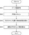
図13に、図12のS18の球面度数の算出処理の処理例のフロー図を示す。 FIG. 13 shows a flowchart of a processing example of the spherical power calculation processing in S18 of FIG.
(S31)
眼科装置1000の動作がS18に移行すると、制御部110は、S11において探索された干渉光LCの検出信号のピーク値のうち所定の波高値以上のピーク値を取得する。なお、所定の波高値以上のピーク値を取得できない場合には、探索されたピーク値の最大値を取得するようにしてもよい。(S31)
When the operation of the
(S32)
制御部110は、第2屈折力算出部121Bにおいて、球面度数として等価球面度数を求める。第2屈折力算出部121Bは、S31においてピーク値が最大となる合焦ミラー85の位置を特定し、0Dの基準位置からの合焦ミラー85の移動量に基づいて等価球面度数を求める。以上で、制御部110は球面度数の算出処理の処理を終了する(エンド)。(S32)
The
S10〜S22、S31〜S32は、実施形態に係る「新たな測定」の一例である。S13〜S17は、実施形態に係る「第1測定制御」の一例である。 S10 to S22 and S31 to S32 are examples of “new measurement” according to the embodiment. S13 to S17 are examples of “first measurement control” according to the embodiment.
[効果]
実施形態に係る眼科装置1000の効果について説明する。[effect]
The effect of the
実施形態に係る眼科装置(たとえば、眼科装置1000)は、第1測定部(たとえば、レフ測定投影系6、レフ測定受光系7、第1屈折力算出部121A)と、第2測定部(たとえば、眼軸長測定系8、第2屈折力算出部121B)と、制御部(たとえば、制御部110)とを含む。第1測定部は、第1光源(たとえば、レフ測定光源61)からの光を被検眼(たとえば、被検眼E)に照射し、その戻り光を検出することにより被検眼の屈折力を測定する。第2測定部は、第2光源(たとえば、OCT光源81)からの光を参照光(たとえば、参照光LR)と測定光(たとえば、測定光LS)とに分割し、測定光を被検眼に照射し、測定光の戻り光と参照光との干渉光(たとえば、干渉光LC)を検出することにより被検眼の少なくとも球面度数を求める。制御部は、第1測定部による測定結果に基づいて、第2測定部に新たな測定を実行させる。 The ophthalmologic apparatus (for example, ophthalmologic apparatus 1000) according to the embodiment includes a first measurement unit (for example, a reflex
このような構成によれば、第1測定部で被検眼Eの屈折力を測定することができない場合であっても、第2測定部を用いて少なくとも球面度数を求めることができる。それにより、白内障が進行した場合であってもIOLの度数を決定することが可能である。 According to such a configuration, even when the refractive power of the eye E cannot be measured by the first measurement unit, at least the spherical power can be obtained using the second measurement unit. Thereby, even if a cataract progresses, it is possible to determine the frequency of IOL.
また、第1測定部は、被検眼に測定パターンを投影し、被検眼からの戻り光に基づくパターン像の形状を解析することにより屈折力を測定し、制御部は、パターン像の形状の解析結果に基づいて新たな測定を第2測定部に実行させてもよい。 The first measurement unit projects a measurement pattern onto the eye to be examined and measures the refractive power by analyzing the shape of the pattern image based on the return light from the eye to be examined. The control unit analyzes the shape of the pattern image. You may make a 2nd measurement part perform a new measurement based on a result.
このような構成によれば、測定パターンの戻り光に基づくパターン像を解析することにより第1測定部による測定ができたか否かを判定することができる。それにより、測定パターンの戻り光に基づくパターン像を用いて被検眼Eの屈折力を測定することができない場合であっても、少なくとも球面度数を求めることができる。それにより、白内障が進行した場合であってもIOLの度数を決定することが可能である。 According to such a configuration, it is possible to determine whether or not the measurement by the first measurement unit has been performed by analyzing the pattern image based on the return light of the measurement pattern. Thereby, even when the refractive power of the eye E cannot be measured using the pattern image based on the return light of the measurement pattern, at least the spherical power can be obtained. Thereby, even if a cataract progresses, it is possible to determine the frequency of IOL.
また、制御部は、新たな測定を第2測定部に実行させる前に、第1測定部の測定条件を変更して屈折力の測定を再実行させることにより得られたパターン像の形状を解析する第1測定制御を実行し、第1測定制御におけるパターン像の形状の解析結果に応じて、第1測定部による再測定または第2測定部による新たな測定を実行させてもよい。 In addition, the control unit analyzes the shape of the pattern image obtained by changing the measurement conditions of the first measurement unit and re-executing the refractive power measurement before causing the second measurement unit to perform a new measurement. The first measurement control may be executed, and remeasurement by the first measurement unit or new measurement by the second measurement unit may be executed according to the analysis result of the shape of the pattern image in the first measurement control.
このような構成によれば、第1測定部の測定条件を変更しつつ第1測定部による測定が可能か否かを判定し、可能であると判定されたとき第1測定部による再測定を実行させるようにしたので、第1測定部を用いてできるだけ正確な測定値を取得することできる。 According to such a configuration, it is determined whether the measurement by the first measurement unit is possible while changing the measurement conditions of the first measurement unit, and when the measurement is determined to be possible, the re-measurement by the first measurement unit is performed. Since it was made to perform, the measured value as accurate as possible can be acquired using the 1st measurement part.
また、制御部は、新たな測定を第2測定部に実行させる前に、測定光の戻り光のピーク位置の検出を行い、ピーク位置が検出された場合に第1測定制御を実行し、ピーク位置が検出されない場合に、第2測定部の測定条件を変更して少なくとも球面度数の測定を再実行させることにより得られた新たな戻り光のピーク位置が検出されたとき第1測定制御を実行するようにしてもよい。 Further, the control unit detects the peak position of the return light of the measurement light before causing the second measurement unit to perform a new measurement, and executes the first measurement control when the peak position is detected, When the position is not detected, the first measurement control is executed when a new peak position of the return light obtained by changing the measurement condition of the second measurement unit and re-executing at least the spherical power measurement is detected. You may make it do.
このような構成によれば、第2測定部の測定条件を変更しつつ第2測定部による測定が可能か否かを判定し、可能であると判定されたとき第2測定部による再測定を実行させるようにしたので、第2測定部を用いてできるだけ正確な測定値を取得することができる。 According to such a configuration, it is determined whether the measurement by the second measurement unit is possible while changing the measurement conditions of the second measurement unit, and when it is determined that the measurement is possible, the second measurement unit performs the remeasurement. Since it was made to perform, the measured value as accurate as possible can be acquired using the 2nd measurement part.
また、第1測定部は、測定光学系(たとえば、レフ測定投影系6、レフ測定受光系7)と、第1検出部(たとえば、撮像素子74)と、第1屈折力算出部(たとえば、第1屈折力算出部121A)とを含んでもよい。測定光学系は、第1光源からの光を被検眼に照射し、被検眼からの戻り光を導く。第1検出部は、測定光学系により導かれた戻り光を検出する。第1屈折力算出部は、第1検出部により得られた戻り光の検出結果に基づいて被検眼の屈折力を求める。制御部は、第1光源からの光の光量、第1検出部による戻り光の検出感度、第1検出部における戻り光の露光時間、および第1検出部により検出された戻り光に基づく像の重ね合わせ枚数のうち少なくとも1つを変更することにより、第1測定部の測定条件を変更する。 The first measurement unit includes a measurement optical system (for example, a reflex
このような構成によれば、第1光源や第1検出部などを制御することにより第1測定部の測定条件を変更するようにしたので、白内障が進行した場合に簡素な制御でIOLの度数を決定することができる。 According to such a configuration, since the measurement conditions of the first measurement unit are changed by controlling the first light source, the first detection unit, and the like, the frequency of the IOL is simply controlled when the cataract progresses. Can be determined.
また、第2測定部は、干渉光学系(たとえば、OCTユニット80)と、第2検出部(たとえば、分光器83)と、第2屈折力算出部(たとえば、第2屈折力算出部121B)とを含んでもよい。干渉光学系は、第2光源からの光を参照光と測定光とに分割し、測定光を被検眼に照射し、その戻り光と参照光との干渉光を生成する。第2検出部は、干渉光を検出する。第2屈折力算出部は、第2検出部により得られた干渉光の検出結果に基づいて少なくとも球面度数を求める。制御部は、第2光源からの光の光量、第2検出部による干渉光の検出感度、第2検出部における干渉光の露光時間、および第2検出部により検出された干渉光に基づく像の重ね合わせ枚数のうち少なくとも1つを変更することにより、第2測定部の測定条件を変更する。 The second measurement unit includes an interference optical system (for example, OCT unit 80), a second detection unit (for example, spectrometer 83), and a second refractive power calculation unit (for example, second refractive power calculation unit 121B). And may be included. The interference optical system divides the light from the second light source into reference light and measurement light, irradiates the eye with the measurement light, and generates interference light between the return light and the reference light. The second detection unit detects interference light. The second refractive power calculation unit obtains at least the spherical power based on the detection result of the interference light obtained by the second detection unit. The control unit controls the amount of light from the second light source, the detection sensitivity of the interference light by the second detection unit, the exposure time of the interference light by the second detection unit, and the image based on the interference light detected by the second detection unit. The measurement condition of the second measurement unit is changed by changing at least one of the superimposed numbers.
このような構成によれば、第2光源や第2検出部などを制御することにより第2測定部の測定条件を変更するようにしたので、白内障が進行した場合に簡素な制御でIOLの度数を決定することができる。 According to such a configuration, since the measurement condition of the second measurement unit is changed by controlling the second light source, the second detection unit, and the like, the frequency of the IOL with simple control when the cataract progresses Can be determined.
また、測定パターンは、リング状のパターンであってもよい。 The measurement pattern may be a ring pattern.
このような構成によれば、第1測定部によりリング上の測定パターンを用いて被検眼の屈折力を測定するようにしたので、一般的なレフ測定を利用しつつ、白内障が進行した場合であってもIOLの度数を決定することができる。 According to such a configuration, since the refractive power of the eye to be examined is measured by the first measurement unit using the measurement pattern on the ring, the cataract progresses while using the general reflex measurement. Even so, the frequency of the IOL can be determined.
また、第2測定部は、眼軸長算出部(たとえば、眼軸長算出部122)を含んでもよい。眼軸長算出部は、干渉光を検出することにより被検眼の眼軸長を求める。 The second measurement unit may include an axial length calculation unit (for example, an axial length calculation unit 122). The axial length calculation unit calculates the axial length of the eye to be examined by detecting the interference light.
このような構成によれば、第1測定部で被検眼Eの屈折力を測定することができない場合に、IOLの度数の算出に用いられる眼軸長の測定系を流用しつつ少なくとも球面度数を求めるようにしたので、IOLの度数を決定するための装置の小型化が可能になる。 According to such a configuration, when the refractive power of the eye E cannot be measured by the first measurement unit, at least the spherical power is obtained while diverting the axial length measurement system used for calculating the power of the IOL. Since it was calculated | required, size reduction of the apparatus for determining the frequency of IOL is attained.
<変形例>
前述の実施形態では、第2屈折力算出部121Bが眼軸長測定系8を用いて球面度数(等価球面度数)だけを求める場合について説明したが、実施形態に係る眼科装置の構成はこれに限定されるものではない。実施形態の変形例に係る第2屈折力算出部は、眼軸長測定系を用いて球面度数、乱視度数、および乱視軸角度を求める。<Modification>
In the above-described embodiment, the case where the second refractive power calculation unit 121B obtains only the spherical power (equivalent spherical power) using the axial
実施形態の変形例に係る眼科装置の構成および動作は、実施形態に係る眼科装置の構成および動作とほぼ同様である。以下では、前述の実施形態と同様の部分について符号をそのまま用い、本変形例について実施形態との相違点を中心に説明する。 The configuration and operation of the ophthalmic apparatus according to the modification of the embodiment are substantially the same as the configuration and operation of the ophthalmic apparatus according to the embodiment. In the following, the same reference numerals are used for the same parts as in the above-described embodiment, and this modification will be described focusing on the differences from the embodiment.
本変形例に係る眼科装置は、図12のS18において、以下のように眼軸長測定系を用いて球面度数、乱視度数、および乱視軸角度を求めることができる。 In S18 of FIG. 12, the ophthalmologic apparatus according to this modification can obtain the spherical power, the astigmatic power, and the astigmatic axis angle using the axial length measurement system as follows.
図14に、本変形例に係る図12のS18の処理例のフロー図を示す。図15および図16に、図14のS43、S44の動作説明図を示す。 FIG. 14 shows a flowchart of the processing example of S18 of FIG. 12 according to this modification. 15 and 16 are diagrams for explaining the operations in S43 and S44 in FIG.
(S41)
本変形例では、眼科装置の動作がS18に移行すると、制御部110は、S11において探索された干渉光LCの検出信号のピーク値のうち所定の波高値以上のピーク値を取得する。なお、所定の波高値以上のピーク値を取得できない場合には、ピーク値の最大値を取得するようにしてもよい。(S41)
In the present modification, when the operation of the ophthalmologic apparatus proceeds to S18, the
(S42)
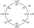
制御部110は、XYスキャナ87により測定光LSを偏向することにより、当該測定光LSで被検眼Eの瞳上を円形スキャンする(たとえば、直径3mmの円周上)。たとえば、図15に示すように、スキャン位置P1〜P8でスキャンされる。(S42)
The
(S43)
第2屈折力算出部121Bは、スキャン位置P1〜P8の各スキャン位置で合焦レンズ85をピーク値が最大となる位置に移動し、その位置から球面度数を求める。S43では、たとえばS31〜S32と同様に、各スキャン位置において球面度数(等価球面度数)が求められる。(S43)
The second refractive power calculator 121B moves the focusing
(S44)
第2屈折力算出部121Bは、S43において求められた各スキャン位置での球面度数の分布から球面度数、乱視度数、および乱視軸角度(レフ値)を求める。(S44)
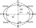
The second refractive power calculation unit 121B obtains the spherical power, the astigmatic power, and the astigmatic axis angle (ref value) from the distribution of the spherical power at each scan position obtained in S43.
各スキャン位置では、前述の合焦レンズ85の位置、すなわち球面度数が乱視度数分だけずれる。第2屈折力算出部121Bは、スキャン位置P1〜P8の各スキャン位置で取得された球面度数を解析することにより被検眼Eの球面度数S、乱視度数C、および乱視軸角度Aを求めることが可能である。たとえば、第2屈折力算出部121Bは、S43で求められた各スキャン位置での球面度数の平均値を求め、求められた平均値を光軸中心位置(重心位置)C1からの各位置までの距離(円形スキャンの半径)と対応付ける。第2屈折力算出部121Bは、各スキャン位置における球面度数と当該平均値との差分を求める。第2屈折力算出部121Bは、中心位置C1を基準に、各スキャン位置での差分を加味した新たな位置P1´〜P8´を特定し、特定された新たな位置に対して楕円近似処理を行うことにより近似楕円AEを特定する(図16)。第2屈折力算出部121Bは、特定された近似楕円AEの長径DLの長さと短径DSの長さとを用いた公知の式にしたがって、球面度数S、乱視度数C、および乱視軸角度Aを求める。 At each scanning position, the position of the focusing
以上で、制御部110は本変形例に係る図12のS18の処理を終了する(エンド)。 Thus, the
このような構成によれば、レフ測定で被検眼Eの屈折力を測定することができない場合であっても、眼軸長測定系を用いて球面度数S、乱視度数C、および乱視軸角度Aを求めることができる。それにより、白内障が進行した場合であってもIOLの度数を従来より高精度に求めることが可能になる。 According to such a configuration, even when the refractive power of the eye E cannot be measured by the reflex measurement, the spherical power S, the astigmatic power C, and the astigmatic shaft angle A using the axial length measurement system. Can be requested. Thereby, even when the cataract progresses, the frequency of the IOL can be obtained with higher accuracy than before.
(その他の変形例)
以上に示された実施形態またはその変形例は、この発明を実施するための一例に過ぎない。この発明を実施しようとする者は、この発明の要旨の範囲内において任意の変形、省略、追加等を施すことが可能である。(Other variations)
The embodiment shown above or its modification is merely an example for carrying out the present invention. A person who intends to implement the present invention can make arbitrary modifications, omissions, additions and the like within the scope of the present invention.
上記の実施形態またはその変形例では、眼軸長測定系を用いて眼軸長を求める例について説明したが、眼軸長測定系を用いて角膜厚や前房深度や水晶体厚についても同様に求めることが可能である。 In the above embodiment or its modification, an example in which the axial length is obtained using the axial length measurement system has been described, but the corneal thickness, anterior chamber depth, and lens thickness are similarly determined using the axial length measurement system. It is possible to ask.
上記の実施形態またはその変形例において説明した光学素子やその配置に限定されるものではない。たとえば、上記の実施形態またはその変形例におけるハーフミラーに代えてビームスプリッターが設けられてもよい。 The present invention is not limited to the optical elements described in the above embodiments or the modifications thereof and the arrangement thereof. For example, a beam splitter may be provided instead of the half mirror in the above-described embodiment or its modification.
眼圧測定機能、眼底撮影機能、前眼部撮影機能、光干渉断層撮影(OCT)機能、超音波検査機能など、眼科分野において使用可能な任意の機能を有する装置に対して、上記の実施形態またはその変形例に係る発明を適用することが可能である。なお、眼圧測定機能は眼圧計等により実現され、眼底撮影機能は眼底カメラや走査型検眼鏡(SLO)等により実現され、前眼部撮影機能はスリットランプ等により実現される。OCT機能は光干渉断層計等により実現され、超音波検査機能は超音波診断装置等により実現される。また、このような機能のうち2つ以上を具備した装置(複合機)に対してこの発明を適用することも可能である。 For the apparatus having any function that can be used in the ophthalmic field, such as an intraocular pressure measurement function, a fundus imaging function, an anterior ocular segment imaging function, an optical coherence tomography (OCT) function, and an ultrasonic examination function Alternatively, the invention according to the modified example can be applied. The intraocular pressure measurement function is realized by a tonometer or the like, the fundus imaging function is realized by a fundus camera, a scanning ophthalmoscope (SLO), or the like, and the anterior ocular segment imaging function is realized by a slit lamp or the like. The OCT function is realized by an optical coherence tomograph or the like, and the ultrasonic inspection function is realized by an ultrasonic diagnostic apparatus or the like. In addition, the present invention can be applied to an apparatus (multifunction machine) having two or more of such functions.
また、上記の実施形態とその変形例の適用が可能なシステムにおいて、動作モードの切り替えにより上記の実施形態とその変形例を択一的に適用にすることが可能である。 Further, in a system to which the above embodiment and its modification can be applied, the above embodiment and its modification can be applied alternatively by switching the operation mode.
1 Zアライメント投影系
2 XYアライメントスポット投影系
3 ケラト測定用リング投影系
4 固視および自覚測定系
5 観察系
6 レフ測定投影系
7 レフ測定受光系
8 眼軸長測定系
9 処理部
10、170 表示部
80 OCTユニット
110 制御部
111 主制御部
112 記憶部
120 演算処理部
121 眼屈折力算出部
121A 第1屈折力算出部
121B 第2屈折力算出部
122 眼軸長算出部
123 IOL度数算出部
1000 眼科装置DESCRIPTION OF SYMBOLS 1 Z
Claims (8)
Translated fromJapanese第2光源からの光を参照光と測定光とに分割し、前記測定光を前記被検眼に照射し、前記測定光の戻り光と前記参照光との干渉光を検出することにより前記被検眼の少なくとも球面度数を求める第2測定部と、
前記第1測定部による測定結果に基づいて、前記第2測定部に新たな測定を実行させる制御部と、
を含む眼科装置。A first measuring unit that measures the refractive power of the eye by irradiating the eye with light from the first light source and detecting the return light;
The eye to be examined is divided by dividing light from a second light source into reference light and measurement light, irradiating the measurement eye with the measurement light, and detecting interference light between the return light of the measurement light and the reference light A second measuring unit for obtaining at least the spherical power of
A control unit that causes the second measurement unit to perform a new measurement based on a measurement result of the first measurement unit;
Ophthalmic device.
前記制御部は、前記パターン像の形状の解析結果に基づいて前記新たな測定を前記第2測定部に実行させる
ことを特徴とする請求項1に記載の眼科装置。The first measurement unit measures the refractive power by projecting a measurement pattern onto the eye to be examined and analyzing the shape of a pattern image based on the return light from the eye to be examined.
The ophthalmic apparatus according to claim 1, wherein the control unit causes the second measurement unit to perform the new measurement based on an analysis result of the shape of the pattern image.
前記新たな測定を前記第2測定部に実行させる前に、前記第1測定部の測定条件を変更して前記屈折力の測定を再実行させることにより得られたパターン像の形状を解析する第1測定制御を実行し、
前記第1測定制御における前記パターン像の形状の解析結果に応じて、前記第1測定部による再測定または前記第2測定部による前記新たな測定を実行させる
ことを特徴とする請求項2に記載の眼科装置。The controller is
Before causing the second measurement unit to perform the new measurement, the shape of the pattern image obtained by changing the measurement conditions of the first measurement unit and re-execution of the refractive power is analyzed. 1 Execute measurement control,
The remeasurement by the first measurement unit or the new measurement by the second measurement unit is executed according to the analysis result of the shape of the pattern image in the first measurement control. Ophthalmic equipment.
前記新たな測定を前記第2測定部に実行させる前に、前記測定光の戻り光のピーク位置の検出を行い、前記ピーク位置が検出された場合に前記第1測定制御を実行し、前記ピーク位置が検出されなかった場合に、前記第2測定部の測定条件を変更して少なくとも球面度数の測定を再実行させることにより得られた新たな戻り光のピーク位置が検出されたとき前記第1測定制御を実行する
ことを特徴とする請求項3に記載の眼科装置。The controller is
Before causing the second measurement unit to perform the new measurement, the peak position of the return light of the measurement light is detected, and when the peak position is detected, the first measurement control is performed, and the peak When the position is not detected, when the new return light peak position obtained by changing the measurement condition of the second measurement unit and re-executing the measurement of at least spherical power is detected, the first The ophthalmologic apparatus according to claim 3, wherein measurement control is executed.
前記第1光源からの光を前記被検眼に照射し、前記被検眼からの戻り光を導く測定光学系と、
前記測定光学系により導かれた戻り光を検出する第1検出部と、
前記第1検出部により得られた前記戻り光の検出結果に基づいて前記被検眼の屈折力を求める第1屈折力算出部と、
を含み、
前記制御部は、前記第1光源からの光の光量、前記第1検出部による前記戻り光の検出感度、前記第1検出部における前記戻り光の露光時間、および前記第1検出部により検出された前記戻り光に基づく像の重ね合わせ枚数のうち少なくとも1つを変更することにより、前記第1測定部の測定条件を変更する
ことを特徴とする請求項3または請求項4に記載の眼科装置。The first measuring unit includes
A measurement optical system that irradiates the eye to be examined with light from the first light source and guides return light from the eye to be examined;
A first detector for detecting return light guided by the measurement optical system;
A first refracting power calculation unit for obtaining a refracting power of the eye to be examined based on a detection result of the return light obtained by the first detecting unit;
Including
The control unit is detected by the light amount of the first light source, the detection sensitivity of the return light by the first detection unit, the exposure time of the return light in the first detection unit, and the first detection unit. 5. The ophthalmic apparatus according to claim 3, wherein the measurement condition of the first measurement unit is changed by changing at least one of the number of superimposed images based on the return light. .
前記第2光源からの光を参照光と測定光とに分割し、前記測定光を前記被検眼に照射し、その戻り光と前記参照光との干渉光を生成する干渉光学系と、
前記干渉光を検出する第2検出部と、
前記第2検出部により得られた前記干渉光の検出結果に基づいて少なくとも前記球面度数を求める第2屈折力算出部と、
を含み、
前記制御部は、前記第2光源からの光の光量、前記第2検出部による前記干渉光の検出感度、前記第2検出部における前記干渉光の露光時間、および前記第2検出部により検出された前記干渉光に基づく像の重ね合わせ枚数のうち少なくとも1つを変更することにより、前記第2測定部の測定条件を変更する
ことを特徴とする請求項3〜請求項5のいずれか一項に記載の眼科装置。The second measuring unit includes
An interference optical system that divides light from the second light source into reference light and measurement light, irradiates the eye to be examined with the measurement light, and generates interference light between the return light and the reference light;
A second detection unit for detecting the interference light;
A second refractive power calculator that obtains at least the spherical power based on the detection result of the interference light obtained by the second detector;
Including
The control unit is detected by the amount of light from the second light source, the detection sensitivity of the interference light by the second detection unit, the exposure time of the interference light in the second detection unit, and the second detection unit. 6. The measurement condition of the second measuring unit is changed by changing at least one of the number of superimposed images based on the interference light. 6. An ophthalmic device according to claim 1.
ことを特徴とする請求項1〜請求項7のいずれか一項に記載の眼科装置。The said 2nd measurement part contains the axial length calculation part which calculates | requires the axial length of the said to-be-tested eye by detecting the said interference light. The Claim 1 characterized by the above-mentioned. Ophthalmic equipment.
Priority Applications (4)
| Application Number | Priority Date | Filing Date | Title |
|---|---|---|---|
| JP2015068981AJP6522390B2 (en) | 2015-03-30 | 2015-03-30 | Ophthalmic device |
| EP17161940.6AEP3222204B1 (en) | 2015-03-30 | 2016-03-17 | Ophthalmologic apparatus |
| EP16160855.9AEP3075303B1 (en) | 2015-03-30 | 2016-03-17 | Ophthalmologic apparatus |
| EP21169153.0AEP3884845A1 (en) | 2015-03-30 | 2016-03-17 | Ophthalmologic apparatus |
Applications Claiming Priority (1)
| Application Number | Priority Date | Filing Date | Title |
|---|---|---|---|
| JP2015068981AJP6522390B2 (en) | 2015-03-30 | 2015-03-30 | Ophthalmic device |
Related Child Applications (2)
| Application Number | Title | Priority Date | Filing Date |
|---|---|---|---|
| JP2017145107ADivisionJP6513747B2 (en) | 2017-07-27 | 2017-07-27 | Ophthalmic device |
| JP2017150085ADivisionJP6518733B2 (en) | 2017-08-02 | 2017-08-02 | Ophthalmic device |
Publications (2)
| Publication Number | Publication Date |
|---|---|
| JP2016187461Atrue JP2016187461A (en) | 2016-11-04 |
| JP6522390B2 JP6522390B2 (en) | 2019-05-29 |
Family
ID=55650134
Family Applications (1)
| Application Number | Title | Priority Date | Filing Date |
|---|---|---|---|
| JP2015068981AActiveJP6522390B2 (en) | 2015-03-30 | 2015-03-30 | Ophthalmic device |
Country Status (2)
| Country | Link |
|---|---|
| EP (3) | EP3075303B1 (en) |
| JP (1) | JP6522390B2 (en) |
Cited By (13)
| Publication number | Priority date | Publication date | Assignee | Title |
|---|---|---|---|---|
| DE102017217060A1 (en) | 2016-09-26 | 2018-03-29 | Omron Automotive Electronics Co., Ltd. | COMMUNICATION SYSTEM FOR A VEHICLE, VEHICLE-ASSEMBLED DEVICE AND PORTABLE DEVICE |
| JP2018164636A (en)* | 2017-03-28 | 2018-10-25 | 株式会社トーメーコーポレーション | Ophthalmologic apparatus |
| JP2019058441A (en)* | 2017-09-27 | 2019-04-18 | 株式会社トプコン | Ophthalmic apparatus and control method thereof |
| JP2019154985A (en)* | 2018-03-16 | 2019-09-19 | 株式会社トプコン | Ophthalmological device |
| WO2019187490A1 (en)* | 2018-03-27 | 2019-10-03 | 株式会社トプコン | Ophthalmic device and method for controlling ophthalmic device |
| JP2019213752A (en)* | 2018-06-14 | 2019-12-19 | 株式会社トプコン | Ophthalmologic apparatus and control method of ophthalmologic apparatus |
| JP2020036818A (en)* | 2018-09-05 | 2020-03-12 | 株式会社トプコン | Image analysis device, image analysis method, and ophthalmic device |
| JP2020142072A (en)* | 2019-03-07 | 2020-09-10 | オクルス オプティクゲレーテ ゲゼルシャフト ミット ベシュレンクテル ハフツング | How to inspect the eye and vision test system |
| JP2021029385A (en)* | 2019-08-20 | 2021-03-01 | 株式会社トーメーコーポレーション | Ophthalmic equipment |
| JP2022042438A (en)* | 2020-09-02 | 2022-03-14 | 株式会社トプコン | Ophthalmic examination system and ophthalmic equipment |
| EP4209171A1 (en) | 2022-01-11 | 2023-07-12 | Topcon Corporation | Ophthalmic apparatus |
| EP4209170A1 (en) | 2022-01-11 | 2023-07-12 | Topcon Corporation | Ophthalmic apparatus |
| JP2023126361A (en)* | 2018-09-18 | 2023-09-07 | 株式会社トプコン | Ophthalmologic apparatus, control method of the same, program and recording medium |
Families Citing this family (8)
| Publication number | Priority date | Publication date | Assignee | Title |
|---|---|---|---|---|
| US11141060B2 (en) | 2019-01-16 | 2021-10-12 | Topcon Corporation | Ophthalmologic apparatus and method of controlling the same |
| US11134836B2 (en) | 2019-01-16 | 2021-10-05 | Topcon Corporation | Ophthalmologic information processing apparatus, ophthalmologic apparatus and ophthalmologic information processing method |
| JP6699956B1 (en) | 2019-01-16 | 2020-05-27 | 株式会社トプコン | Ophthalmic device |
| US11439301B2 (en) | 2019-01-16 | 2022-09-13 | Topcon Corporation | Ophthalmologic information processing apparatus, ophthalmologic apparatus and ophthalmologic information processing method |
| DE102019101409B4 (en) | 2019-01-21 | 2021-12-30 | Oculus Optikgeräte GmbH | Procedure and vision testing system for examining eyes |
| JP7367509B2 (en)* | 2019-12-13 | 2023-10-24 | 株式会社ニデック | Ophthalmology measurement equipment, ophthalmology measurement system, and ophthalmology measurement program |
| US11963722B2 (en) | 2021-04-13 | 2024-04-23 | Amo Development, Llc | Methods and systems for determining change in eye position between successive eye measurements |
| DE102022113798A1 (en)* | 2022-06-01 | 2023-12-07 | Heidelberg Engineering Gmbh | Device for carrying out optical coherence tomography |
Citations (14)
| Publication number | Priority date | Publication date | Assignee | Title |
|---|---|---|---|---|
| JPH07213489A (en)* | 1994-02-07 | 1995-08-15 | Topcon Corp | Living eye measuring device |
| JPH07255674A (en)* | 1994-03-18 | 1995-10-09 | Topcon Corp | Device for measuring eye size |
| JPH0898815A (en)* | 1994-09-30 | 1996-04-16 | Canon Inc | Ophthalmic examination device |
| JP2004159669A (en)* | 2001-11-09 | 2004-06-10 | Topcon Corp | Eye characteristics measurement device |
| JP2005342204A (en)* | 2004-06-03 | 2005-12-15 | Nidek Co Ltd | Ophthalmologic measuring apparatus |
| JP2006187483A (en)* | 2005-01-07 | 2006-07-20 | Nidek Co Ltd | Eye refractive power measuring device |
| JP2007089715A (en)* | 2005-09-27 | 2007-04-12 | Nidek Co Ltd | Eye refraction measuring apparatus |
| WO2007066465A1 (en)* | 2005-12-07 | 2007-06-14 | Kabushiki Kaisha Topcon | Optical image measuring instrument |
| US20070279592A1 (en)* | 2006-05-29 | 2007-12-06 | Nidek Co., Ltd. | Ocular depth dimension measurement apparatus |
| JP2012110672A (en)* | 2010-11-05 | 2012-06-14 | Nidek Co Ltd | Ophthalmologic device |
| US20120197102A1 (en)* | 2011-01-27 | 2012-08-02 | Nidek Co., Ltd. | Ophthalmic surgical microscope |
| JP2013165819A (en)* | 2012-02-15 | 2013-08-29 | Canon Inc | Ophthalmologic apparatus, ophthalmologic control method, and program |
| JP2014209994A (en)* | 2013-04-17 | 2014-11-13 | キヤノン株式会社 | Ophthalmologic apparatus, control method of ophthalmologic apparatus, and program |
| US20150320308A1 (en)* | 2012-12-27 | 2015-11-12 | Kabushiki Kaisha Topcon | Ophthalmologic imaging apparatus |
Family Cites Families (2)
| Publication number | Priority date | Publication date | Assignee | Title |
|---|---|---|---|---|
| JP3276177B2 (en)* | 1991-10-25 | 2002-04-22 | 株式会社トプコン | Biological eye size measuring device with refractive power correction function |
| JP2016077774A (en)* | 2014-10-22 | 2016-05-16 | 株式会社トプコン | Ophthalmologic apparatus |
- 2015
- 2015-03-30JPJP2015068981Apatent/JP6522390B2/enactiveActive
- 2016
- 2016-03-17EPEP16160855.9Apatent/EP3075303B1/enactiveActive
- 2016-03-17EPEP21169153.0Apatent/EP3884845A1/ennot_activeWithdrawn
- 2016-03-17EPEP17161940.6Apatent/EP3222204B1/enactiveActive
Patent Citations (14)
| Publication number | Priority date | Publication date | Assignee | Title |
|---|---|---|---|---|
| JPH07213489A (en)* | 1994-02-07 | 1995-08-15 | Topcon Corp | Living eye measuring device |
| JPH07255674A (en)* | 1994-03-18 | 1995-10-09 | Topcon Corp | Device for measuring eye size |
| JPH0898815A (en)* | 1994-09-30 | 1996-04-16 | Canon Inc | Ophthalmic examination device |
| JP2004159669A (en)* | 2001-11-09 | 2004-06-10 | Topcon Corp | Eye characteristics measurement device |
| JP2005342204A (en)* | 2004-06-03 | 2005-12-15 | Nidek Co Ltd | Ophthalmologic measuring apparatus |
| JP2006187483A (en)* | 2005-01-07 | 2006-07-20 | Nidek Co Ltd | Eye refractive power measuring device |
| JP2007089715A (en)* | 2005-09-27 | 2007-04-12 | Nidek Co Ltd | Eye refraction measuring apparatus |
| WO2007066465A1 (en)* | 2005-12-07 | 2007-06-14 | Kabushiki Kaisha Topcon | Optical image measuring instrument |
| US20070279592A1 (en)* | 2006-05-29 | 2007-12-06 | Nidek Co., Ltd. | Ocular depth dimension measurement apparatus |
| JP2012110672A (en)* | 2010-11-05 | 2012-06-14 | Nidek Co Ltd | Ophthalmologic device |
| US20120197102A1 (en)* | 2011-01-27 | 2012-08-02 | Nidek Co., Ltd. | Ophthalmic surgical microscope |
| JP2013165819A (en)* | 2012-02-15 | 2013-08-29 | Canon Inc | Ophthalmologic apparatus, ophthalmologic control method, and program |
| US20150320308A1 (en)* | 2012-12-27 | 2015-11-12 | Kabushiki Kaisha Topcon | Ophthalmologic imaging apparatus |
| JP2014209994A (en)* | 2013-04-17 | 2014-11-13 | キヤノン株式会社 | Ophthalmologic apparatus, control method of ophthalmologic apparatus, and program |
Cited By (27)
| Publication number | Priority date | Publication date | Assignee | Title |
|---|---|---|---|---|
| DE102017217060A1 (en) | 2016-09-26 | 2018-03-29 | Omron Automotive Electronics Co., Ltd. | COMMUNICATION SYSTEM FOR A VEHICLE, VEHICLE-ASSEMBLED DEVICE AND PORTABLE DEVICE |
| JP2018164636A (en)* | 2017-03-28 | 2018-10-25 | 株式会社トーメーコーポレーション | Ophthalmologic apparatus |
| JP2022145804A (en)* | 2017-03-28 | 2022-10-04 | 株式会社トーメーコーポレーション | Ophthalmological device |
| US11659992B2 (en) | 2017-03-28 | 2023-05-30 | Tomey Corporation | Ophthalmic apparatus |
| JP2021180959A (en)* | 2017-09-27 | 2021-11-25 | 株式会社トプコン | Ophthalmologic apparatus and control method thereof |
| JP7213315B2 (en) | 2017-09-27 | 2023-01-26 | 株式会社トプコン | Ophthalmic device and its control method |
| JP2019058441A (en)* | 2017-09-27 | 2019-04-18 | 株式会社トプコン | Ophthalmic apparatus and control method thereof |
| JP7460710B2 (en) | 2018-03-16 | 2024-04-02 | 株式会社トプコン | Ophthalmic Equipment |
| JP2019154985A (en)* | 2018-03-16 | 2019-09-19 | 株式会社トプコン | Ophthalmological device |
| JP2022164860A (en)* | 2018-03-16 | 2022-10-27 | 株式会社トプコン | ophthalmic equipment |
| WO2019187490A1 (en)* | 2018-03-27 | 2019-10-03 | 株式会社トプコン | Ophthalmic device and method for controlling ophthalmic device |
| US11896307B2 (en) | 2018-03-27 | 2024-02-13 | Topcon Corporation | Ophthalmologic apparatus and method of controlling same |
| JP2019213752A (en)* | 2018-06-14 | 2019-12-19 | 株式会社トプコン | Ophthalmologic apparatus and control method of ophthalmologic apparatus |
| JP7164328B2 (en) | 2018-06-14 | 2022-11-01 | 株式会社トプコン | Ophthalmic device and control method for ophthalmic device |
| JP2020036818A (en)* | 2018-09-05 | 2020-03-12 | 株式会社トプコン | Image analysis device, image analysis method, and ophthalmic device |
| JP7128065B2 (en) | 2018-09-05 | 2022-08-30 | 株式会社トプコン | Image analysis device, image analysis method, and ophthalmic device |
| JP2023126361A (en)* | 2018-09-18 | 2023-09-07 | 株式会社トプコン | Ophthalmologic apparatus, control method of the same, program and recording medium |
| JP7609932B2 (en) | 2018-09-18 | 2025-01-07 | 株式会社トプコン | Ophthalmic apparatus, control method thereof, program, and recording medium |
| JP2020142072A (en)* | 2019-03-07 | 2020-09-10 | オクルス オプティクゲレーテ ゲゼルシャフト ミット ベシュレンクテル ハフツング | How to inspect the eye and vision test system |
| JP7572150B2 (en) | 2019-03-07 | 2024-10-23 | オクルス オプティクゲレーテ ゲゼルシャフト ミット ベシュレンクテル ハフツング | Eye examination method and vision examination system |
| JP7349713B2 (en) | 2019-08-20 | 2023-09-25 | 株式会社トーメーコーポレーション | ophthalmology equipment |
| JP2021029385A (en)* | 2019-08-20 | 2021-03-01 | 株式会社トーメーコーポレーション | Ophthalmic equipment |
| JP2022042438A (en)* | 2020-09-02 | 2022-03-14 | 株式会社トプコン | Ophthalmic examination system and ophthalmic equipment |
| JP7517914B2 (en) | 2020-09-02 | 2024-07-17 | 株式会社トプコン | Ophthalmic examination system and ophthalmic device |
| US12245815B2 (en) | 2020-09-02 | 2025-03-11 | Topcon Corporation | Ophthalmologic examination system and ophthalmologic apparatus |
| EP4209171A1 (en) | 2022-01-11 | 2023-07-12 | Topcon Corporation | Ophthalmic apparatus |
| EP4209170A1 (en) | 2022-01-11 | 2023-07-12 | Topcon Corporation | Ophthalmic apparatus |
Also Published As
| Publication number | Publication date |
|---|---|
| JP6522390B2 (en) | 2019-05-29 |
| EP3075303A1 (en) | 2016-10-05 |
| EP3884845A1 (en) | 2021-09-29 |
| EP3075303B1 (en) | 2021-04-21 |
| EP3222204B1 (en) | 2021-04-21 |
| EP3222204A1 (en) | 2017-09-27 |
Similar Documents
| Publication | Publication Date | Title |
|---|---|---|
| JP6522390B2 (en) | Ophthalmic device | |
| JP7304780B2 (en) | ophthalmic equipment | |
| WO2016063722A1 (en) | Ophthalmic apparatus | |
| JP6613103B2 (en) | Ophthalmic equipment | |
| JP6825042B2 (en) | Ophthalmic equipment | |
| WO2017135015A1 (en) | Ophthalmological device and ophthalmological inspection system | |
| JP6603545B2 (en) | Ophthalmic equipment | |
| JP2018117693A (en) | Ophthalmic equipment | |
| JP6513747B2 (en) | Ophthalmic device | |
| JP6654378B2 (en) | Ophthalmic equipment | |
| JP2023002745A (en) | ophthalmic equipment | |
| JP7660618B2 (en) | Ophthalmic device and control method thereof | |
| JP6453096B2 (en) | Ophthalmic equipment | |
| JP6795360B2 (en) | Ophthalmic lens measuring device | |
| JP6518733B2 (en) | Ophthalmic device | |
| JP7292072B2 (en) | ophthalmic equipment | |
| JP7281877B2 (en) | ophthalmic equipment | |
| JP7116572B2 (en) | Ophthalmic device and ophthalmic information processing program | |
| JP6619197B2 (en) | Ophthalmic equipment | |
| JP6766242B2 (en) | Ophthalmic equipment | |
| JP7201855B2 (en) | Ophthalmic device and ophthalmic information processing program | |
| JP7103813B2 (en) | Ophthalmic equipment | |
| JP2019198724A (en) | Ophthalmologic apparatus |
Legal Events
| Date | Code | Title | Description |
|---|---|---|---|
| RD01 | Notification of change of attorney | Free format text:JAPANESE INTERMEDIATE CODE: A7421 Effective date:20161226 | |
| A621 | Written request for application examination | Free format text:JAPANESE INTERMEDIATE CODE: A621 Effective date:20180214 | |
| A977 | Report on retrieval | Free format text:JAPANESE INTERMEDIATE CODE: A971007 Effective date:20181121 | |
| A131 | Notification of reasons for refusal | Free format text:JAPANESE INTERMEDIATE CODE: A131 Effective date:20181127 | |
| A521 | Request for written amendment filed | Free format text:JAPANESE INTERMEDIATE CODE: A523 Effective date:20181129 | |
| TRDD | Decision of grant or rejection written | ||
| A01 | Written decision to grant a patent or to grant a registration (utility model) | Free format text:JAPANESE INTERMEDIATE CODE: A01 Effective date:20190423 | |
| A61 | First payment of annual fees (during grant procedure) | Free format text:JAPANESE INTERMEDIATE CODE: A61 Effective date:20190424 | |
| R150 | Certificate of patent or registration of utility model | Ref document number:6522390 Country of ref document:JP Free format text:JAPANESE INTERMEDIATE CODE: R150 | |
| R250 | Receipt of annual fees | Free format text:JAPANESE INTERMEDIATE CODE: R250 | |
| R250 | Receipt of annual fees | Free format text:JAPANESE INTERMEDIATE CODE: R250 | |
| R250 | Receipt of annual fees | Free format text:JAPANESE INTERMEDIATE CODE: R250 | |
| R250 | Receipt of annual fees | Free format text:JAPANESE INTERMEDIATE CODE: R250 |