JP2016181826A - Terminal, processing device, processing system and program - Google Patents
Terminal, processing device, processing system and programDownload PDFInfo
- Publication number
- JP2016181826A JP2016181826AJP2015061407AJP2015061407AJP2016181826AJP 2016181826 AJP2016181826 AJP 2016181826AJP 2015061407 AJP2015061407 AJP 2015061407AJP 2015061407 AJP2015061407 AJP 2015061407AJP 2016181826 AJP2016181826 AJP 2016181826A
- Authority
- JP
- Japan
- Prior art keywords
- connection
- terminal
- communication path
- processing device
- information
- Prior art date
- Legal status (The legal status is an assumption and is not a legal conclusion. Google has not performed a legal analysis and makes no representation as to the accuracy of the status listed.)
- Granted
Links
- 238000012545processingMethods0.000titleclaimsabstractdescription110
- 238000004891communicationMethods0.000claimsabstractdescription206
- 230000005540biological transmissionEffects0.000claimsabstractdescription23
- 230000004044responseEffects0.000claimsdescription29
- 238000001514detection methodMethods0.000claimsdescription24
- 238000000034methodMethods0.000claimsdescription17
- 238000012546transferMethods0.000claimsdescription6
- 238000010586diagramMethods0.000description15
- 239000000523sampleSubstances0.000description10
- 238000012986modificationMethods0.000description7
- 230000004048modificationEffects0.000description7
- 230000006870functionEffects0.000description5
- 230000015572biosynthetic processEffects0.000description2
- 239000004973liquid crystal related substanceSubstances0.000description2
- 230000003287optical effectEffects0.000description2
- 239000007787solidSubstances0.000description2
- 238000004590computer programMethods0.000description1
- 238000005516engineering processMethods0.000description1
- 230000007774longtermEffects0.000description1
- 238000012544monitoring processMethods0.000description1
- 230000002093peripheral effectEffects0.000description1
- 239000004065semiconductorSubstances0.000description1
- 238000013519translationMethods0.000description1
Images


Classifications
- H—ELECTRICITY
- H04—ELECTRIC COMMUNICATION TECHNIQUE
- H04W—WIRELESS COMMUNICATION NETWORKS
- H04W12/00—Security arrangements; Authentication; Protecting privacy or anonymity
- H04W12/04—Key management, e.g. using generic bootstrapping architecture [GBA]
- H—ELECTRICITY
- H04—ELECTRIC COMMUNICATION TECHNIQUE
- H04L—TRANSMISSION OF DIGITAL INFORMATION, e.g. TELEGRAPHIC COMMUNICATION
- H04L67/00—Network arrangements or protocols for supporting network services or applications
- H04L67/01—Protocols
- H04L67/02—Protocols based on web technology, e.g. hypertext transfer protocol [HTTP]
- H—ELECTRICITY
- H04—ELECTRIC COMMUNICATION TECHNIQUE
- H04L—TRANSMISSION OF DIGITAL INFORMATION, e.g. TELEGRAPHIC COMMUNICATION
- H04L51/00—User-to-user messaging in packet-switching networks, transmitted according to store-and-forward or real-time protocols, e.g. e-mail
- H04L51/42—Mailbox-related aspects, e.g. synchronisation of mailboxes
- H—ELECTRICITY
- H04—ELECTRIC COMMUNICATION TECHNIQUE
- H04L—TRANSMISSION OF DIGITAL INFORMATION, e.g. TELEGRAPHIC COMMUNICATION
- H04L67/00—Network arrangements or protocols for supporting network services or applications
- H04L67/14—Session management
- H04L67/141—Setup of application sessions
- H—ELECTRICITY
- H04—ELECTRIC COMMUNICATION TECHNIQUE
- H04L—TRANSMISSION OF DIGITAL INFORMATION, e.g. TELEGRAPHIC COMMUNICATION
- H04L69/00—Network arrangements, protocols or services independent of the application payload and not provided for in the other groups of this subclass
- H04L69/40—Network arrangements, protocols or services independent of the application payload and not provided for in the other groups of this subclass for recovering from a failure of a protocol instance or entity, e.g. service redundancy protocols, protocol state redundancy or protocol service redirection
- H—ELECTRICITY
- H04—ELECTRIC COMMUNICATION TECHNIQUE
- H04N—PICTORIAL COMMUNICATION, e.g. TELEVISION
- H04N1/00—Scanning, transmission or reproduction of documents or the like, e.g. facsimile transmission; Details thereof
- H04N1/00127—Connection or combination of a still picture apparatus with another apparatus, e.g. for storage, processing or transmission of still picture signals or of information associated with a still picture
- H04N1/00204—Connection or combination of a still picture apparatus with another apparatus, e.g. for storage, processing or transmission of still picture signals or of information associated with a still picture with a digital computer or a digital computer system, e.g. an internet server
- H—ELECTRICITY
- H04—ELECTRIC COMMUNICATION TECHNIQUE
- H04N—PICTORIAL COMMUNICATION, e.g. TELEVISION
- H04N1/00—Scanning, transmission or reproduction of documents or the like, e.g. facsimile transmission; Details thereof
- H04N1/00127—Connection or combination of a still picture apparatus with another apparatus, e.g. for storage, processing or transmission of still picture signals or of information associated with a still picture
- H04N1/00281—Connection or combination of a still picture apparatus with another apparatus, e.g. for storage, processing or transmission of still picture signals or of information associated with a still picture with a telecommunication apparatus, e.g. a switched network of teleprinters for the distribution of text-based information, a selective call terminal
- H04N1/00307—Connection or combination of a still picture apparatus with another apparatus, e.g. for storage, processing or transmission of still picture signals or of information associated with a still picture with a telecommunication apparatus, e.g. a switched network of teleprinters for the distribution of text-based information, a selective call terminal with a mobile telephone apparatus
- H—ELECTRICITY
- H04—ELECTRIC COMMUNICATION TECHNIQUE
- H04W—WIRELESS COMMUNICATION NETWORKS
- H04W12/00—Security arrangements; Authentication; Protecting privacy or anonymity
- H04W12/50—Secure pairing of devices
- H—ELECTRICITY
- H04—ELECTRIC COMMUNICATION TECHNIQUE
- H04W—WIRELESS COMMUNICATION NETWORKS
- H04W76/00—Connection management
- H04W76/10—Connection setup
- H04W76/14—Direct-mode setup
- H—ELECTRICITY
- H04—ELECTRIC COMMUNICATION TECHNIQUE
- H04N—PICTORIAL COMMUNICATION, e.g. TELEVISION
- H04N2201/00—Indexing scheme relating to scanning, transmission or reproduction of documents or the like, and to details thereof
- H04N2201/0077—Types of the still picture apparatus
- H04N2201/0094—Multifunctional device, i.e. a device capable of all of reading, reproducing, copying, facsimile transception, file transception
- H—ELECTRICITY
- H04—ELECTRIC COMMUNICATION TECHNIQUE
- H04N—PICTORIAL COMMUNICATION, e.g. TELEVISION
- H04N2201/00—Indexing scheme relating to scanning, transmission or reproduction of documents or the like, and to details thereof
- H04N2201/32—Circuits or arrangements for control or supervision between transmitter and receiver or between image input and image output device, e.g. between a still-image camera and its memory or between a still-image camera and a printer device
- H04N2201/3201—Display, printing, storage or transmission of additional information, e.g. ID code, date and time or title
- H04N2201/3225—Display, printing, storage or transmission of additional information, e.g. ID code, date and time or title of data relating to an image, a page or a document
- H04N2201/3256—Display, printing, storage or transmission of additional information, e.g. ID code, date and time or title of data relating to an image, a page or a document colour related metadata, e.g. colour, ICC profiles
- H04N2201/326—Display, printing, storage or transmission of additional information, e.g. ID code, date and time or title of data relating to an image, a page or a document colour related metadata, e.g. colour, ICC profiles relating to the rendering or output medium, device or process, e.g. monitor, paper or printer profile
- H—ELECTRICITY
- H04—ELECTRIC COMMUNICATION TECHNIQUE
- H04W—WIRELESS COMMUNICATION NETWORKS
- H04W84/00—Network topologies
- H04W84/02—Hierarchically pre-organised networks, e.g. paging networks, cellular networks, WLAN [Wireless Local Area Network] or WLL [Wireless Local Loop]
- H04W84/10—Small scale networks; Flat hierarchical networks
- H04W84/12—WLAN [Wireless Local Area Networks]
Landscapes
- Engineering & Computer Science (AREA)
- Signal Processing (AREA)
- Computer Networks & Wireless Communication (AREA)
- Computer Security & Cryptography (AREA)
- Multimedia (AREA)
- General Engineering & Computer Science (AREA)
- Computing Systems (AREA)
- Human Computer Interaction (AREA)
- Information Transfer Between Computers (AREA)
- Facsimiles In General (AREA)
- Telephone Function (AREA)
- Mobile Radio Communication Systems (AREA)
- Business, Economics & Management (AREA)
- General Business, Economics & Management (AREA)
Abstract
Description
Translated fromJapanese本発明は、端末、処理装置、処理システムおよびプログラムに関する。 The present invention relates to a terminal, a processing device, a processing system, and a program.
特許文献1には、それぞれにNFC(Near Field Communication)デバイスが使われているホスト装置と周辺装置とを十分に近くに置くことで、両者間のペアリングを行って、無線ネットワークを確立する技術が開示されている。
処理装置と端末装置等の装置間で一対一の無線通信接続を行う際に、双方の装置で無線通信手段とは異なるNFC通信手段を設け、無線通信接続のための接続情報をNFCタグ情報として交換し共有することにより、無線通信接続を行う技術が知られているが、この技術を利用するためには、NFC通信手段が更に必要となる。また、処理装置が端末と接続した際に、接続のための情報を双方の機器で記憶し、一旦接続が解除された後に再接続する際に双方の機器で記憶した接続のための情報を用いて接続を行うことにより、利用者が接続のために行う処理(ボタンを押す処理や文字列情報を入力して接続情報を交換する処理など)を省略する技術も知られている。処理装置が、複数の利用者の端末から接続されて利用される共用の装置である場合に、接続を行った端末の数だけ接続情報を記憶できるとは限らない。本発明は、処理装置と端末とが相互に接続した後、二回目以降に接続する際に、処理装置で接続情報を記憶していない場合であっても、利用者の操作負担を軽減することを目的とする。 When a one-to-one wireless communication connection is made between a processing device and a device such as a terminal device, NFC communication means different from the wireless communication means is provided in both devices, and connection information for wireless communication connection is used as NFC tag information. A technique for performing wireless communication connection by exchanging and sharing is known, but in order to use this technique, NFC communication means is further required. Also, when the processing device is connected to the terminal, the information for connection is stored in both devices, and the connection information stored in both devices is used when reconnecting after the connection is once released. There is also known a technique that eliminates processing (for example, processing for pressing a button or processing for exchanging connection information by inputting character string information) performed by a user for connection. When the processing apparatus is a shared apparatus that is connected and used from a plurality of user terminals, the connection information cannot always be stored as many as the number of connected terminals. The present invention reduces the operation burden on the user even when the connection information is not stored in the processing device when the processing device and the terminal are connected to each other and then connected after the second time. With the goal.
本発明の請求項1に係る端末は、無線通信による第1通信路において接続情報を使用して処理装置と接続する接続手段と、前記第1通信路において接続した前記処理装置の識別情報を取得する取得手段と、前記第1通信路において前記接続情報と前記識別情報とを対応づけて記憶する記憶手段と、前記第1通信路による前記処理装置との接続が切断されていることを検知する検知手段と、前記検知手段により前記処理装置との前記接続が切断されていることが検知されたときに、前記記憶手段に記憶した前記接続情報と前記識別情報とを用いて、該処理装置が自端末と接続したときに使用した接続情報を前記第1通信路とは異なる第2通信路経由で該処理装置に送信する送信手段と、を有することを特徴とする。
本発明の請求項2に係る端末は、請求項1に記載の態様において、前記識別情報は、メールアドレスであり、前記送信手段は、前記接続情報を含むメールを前記処理装置に送信することを特徴とする。
本発明の請求項3に係る端末は、請求項1に記載の態様において、前記識別情報は、IP(Internet Protocol)アドレスであり、前記送信手段は、TCP(Transmission Control Protocol)/IPを用いて前記接続情報を前記処理装置に送信することを特徴とする。
本発明の請求項4に係る端末は、請求項1に記載の態様において、前記識別情報は、URL(Uniform Resource Locator)であり、前記送信手段は、HTTP(Hyper Text Transfer Protocol)を用いて前記接続情報を前記処理装置に送信することを特徴とする。
本発明の請求項5に係る端末は、請求項1から4のいずれか1項に記載の態様において、前記接続手段は、暗号化された情報を前記第1通信路経由で通信するための鍵を示す鍵情報と、該鍵を生成するために用いられるパスフレーズとを含むことを特徴とする。
本発明の請求項6に係る端末は、請求項1または2に記載の態様において、前記検知手段は、前記処理装置から決められた期間にわたって前記第1通信路による接続のための応答がない場合に、前記処理装置との接続が切断されていることを検知することを特徴とする。
本発明の請求項7に係る処理装置は、無線通信による第1通信路において接続情報を使用して端末と接続する接続手段と、前記第1通信路において接続した前記端末に自装置の識別情報を供給する供給手段と、前記第1通信路による前記端末との接続が切断されているときに、前記接続情報を前記第1通信路とは異なる第2通信路経由で該端末から受信する受信手段と、を備え、前記接続手段は、前記受信した前記接続情報を用いて前記端末と接続することを特徴とする。
本発明の請求項8に係る処理装置は、請求項7に記載の態様において、前記識別情報は、メールアドレスであり、前記受信手段は、前記接続情報を含むメールを前記端末から受信することを特徴とする。
本発明の請求項9に係る処理装置は、請求項7に記載の態様において、前記識別情報は、IP(Internet Protocol)アドレスであり、前記受信手段は、TCP(Transmission Control Protocol)/IPを用いて前記接続情報を前記端末から受信することを特徴とする。
本発明の請求項10に係る処理装置は、請求項7に記載の態様において、前記識別情報は、URL(Uniform Resource Locator)であり、前記受信手段は、HTTP(Hyper Text Transfer Protocol)を用いて前記接続情報を前記端末から受信することを特徴とする。
本発明の請求項11に係る処理装置は、請求項7から10のいずれか1項に記載の態様において、自装置の記憶手段に記憶された前記接続情報が失われている場合に、前記端末との接続が切断されていることを検知する検知手段を有し、前記受信手段は、前記検知手段により前記接続が切断されていることが検知されたときに、受信した接続情報を前記記憶手段に記憶させ、前記接続手段は、前記記憶手段に記憶された接続情報を使用して、前記第1通信路において端末と接続することを特徴とする。
本発明の請求項12に係る処理装置は、請求項7から11のいずれか1項に記載の態様において、前記接続手段により前記端末と接続しているときに、該端末から処理の指示を受付ける受付手段と、前記受付手段が受付けた指示に応じて前記処理を実行する実行手段と、を有することを特徴とする。
本発明の請求項13に係る処理システムは、端末と処理装置とを有する処理システムであって、前記端末は、無線通信による第1通信路において第1接続情報を使用して処理装置と接続する第1接続手段と、前記第1通信路において接続した前記処理装置の識別情報を取得する取得手段と、前記第1通信路において前記第1接続情報と前記識別情報とを対応づけて記憶する記憶手段と、前記第1通信路による前記処理装置との接続が切断されていることを検知する検知手段と、前記検知手段により前記処理装置との前記接続が切断されていることが検知されたときに、前記記憶手段に記憶した前記第1接続情報と前記識別情報とを用いて、該処理装置が自端末と接続したときに使用した第2接続情報を前記第1通信路とは異なる第2通信路経由で該処理装置に送信する送信手段と、を有し、前記処理装置は、無線通信による前記第1通信路において前記第2接続情報を使用して前記端末と接続する第2接続手段と、前記第1通信路において接続した前記端末に自装置の識別情報を供給する供給手段と、前記第1通信路による前記端末との接続が切断されているときに、前記第2接続情報を前記第2通信路経由で該端末から受信する受信手段と、前記第2接続手段により前記端末と接続しているときに、該端末から処理の指示を受付ける受付手段と、前記受付手段が受付けた指示に応じて前記処理を実行する実行手段と、を有し、前記第2接続手段は、前記受信手段により受信した前記第2接続情報を用いて前記端末と接続することを特徴とする。
本発明の請求項14に係るプログラムは、コンピュータを、無線通信による第1通信路において接続情報を使用して処理装置と接続する接続手段と、前記第1通信路において接続した前記処理装置の識別情報を取得する取得手段と、前記第1通信路において前記接続情報と前記識別情報とを対応づけて記憶する記憶手段と、前記第1通信路による前記処理装置との接続が切断されていることを検知する検知手段と、前記検知手段により前記処理装置との前記接続が切断されていることが検知されたときに、前記記憶手段に記憶した前記接続情報と前記識別情報とを用いて、該処理装置が自端末と接続したときに使用した接続情報を前記第1通信路とは異なる第2通信路経由で該処理装置に送信する送信手段として機能させるためのプログラムである。
本発明の請求項15に係るプログラムは、コンピュータを、無線通信による第1通信路において接続情報を使用して端末と接続する接続手段と、前記第1通信路において接続した前記端末に自装置の識別情報を供給する供給手段と、前記第1通信路による前記端末との接続が切断されているときに、前記接続情報を前記第1通信路とは異なる第2通信路経由で該端末から受信する受信手段として機能させるとともに、前記接続手段が、前記受信した前記接続情報を用いて前記端末と接続するように機能させるためのプログラムである。The terminal according to
A terminal according to
The terminal according to
The terminal according to
A terminal according to claim 5 of the present invention is the terminal according to any one of
The terminal according to claim 6 of the present invention is the terminal according to
A processing device according to claim 7 of the present invention is a connection means for connecting to a terminal using connection information in a first communication path by wireless communication, and identification information of the own apparatus to the terminal connected in the first communication path. Receiving the connection information from the terminal via a second communication path different from the first communication path when the connection between the supply means for supplying the terminal and the terminal via the first communication path is disconnected And the connection means connects to the terminal using the received connection information.
The processing device according to claim 8 of the present invention is the processing device according to claim 7, wherein the identification information is a mail address, and the receiving means receives a mail including the connection information from the terminal. Features.
The processing device according to
The processing device according to claim 10 of the present invention is the processing device according to claim 7, wherein the identification information is a URL (Uniform Resource Locator), and the receiving means uses HTTP (Hyper Text Transfer Protocol). The connection information is received from the terminal.
A processing device according to an eleventh aspect of the present invention is the processing device according to any one of the seventh to tenth aspects, wherein the connection information stored in the storage means of the own device is lost. Detecting means for detecting that the connection is disconnected, and the receiving means stores the received connection information when the detection means detects that the connection is disconnected. And the connection means uses the connection information stored in the storage means to connect to the terminal in the first communication path.
A processing device according to
A processing system according to a thirteenth aspect of the present invention is a processing system having a terminal and a processing device, and the terminal connects to the processing device using first connection information in a first communication path by wireless communication. A first connection means, an acquisition means for acquiring identification information of the processing device connected in the first communication path, and a memory for storing the first connection information and the identification information in association with each other in the first communication path A means for detecting that the connection with the processing apparatus via the first communication path is disconnected, and when the detection means detects that the connection with the processing apparatus is disconnected In addition, the second connection information used when the processing apparatus is connected to its own terminal using the first connection information and the identification information stored in the storage means is different from the first communication path. Communication path Transmitting means for transmitting to the processing device, wherein the processing device uses the second connection information in the first communication path by wireless communication to connect to the terminal, and When the connection between the supply means for supplying identification information of the device itself to the terminal connected in the first communication path and the terminal through the first communication path is disconnected, the second connection information is changed to the second connection information. A receiving means for receiving from the terminal via a communication path; a receiving means for receiving a processing instruction from the terminal when connected to the terminal by the second connecting means; and an instruction received by the receiving means And executing means for executing the processing, wherein the second connection means is connected to the terminal using the second connection information received by the receiving means.
According to a fourteenth aspect of the present invention, there is provided a program for connecting a computer to a processing device using connection information in a first communication path by wireless communication, and identifying the processing device connected in the first communication path. The connection between the acquisition means for acquiring information, the storage means for associating and storing the connection information and the identification information in the first communication path, and the processing device via the first communication path is disconnected. When detecting that the connection with the processing device is disconnected by the detection means, and using the connection information and the identification information stored in the storage means, A program for functioning as transmission means for transmitting connection information used when a processing device is connected to its own terminal to the processing device via a second communication path different from the first communication path A.
According to a fifteenth aspect of the present invention, there is provided a program for connecting a computer to a terminal using connection information in a first communication path by wireless communication, and a terminal connected to the terminal connected in the first communication path. The connection information is received from the terminal via a second communication path different from the first communication path when the connection between the supply means for supplying identification information and the terminal via the first communication path is disconnected. And a program for causing the connection means to function to connect to the terminal using the received connection information.
請求項1、13〜15に係る発明によれば、処理装置と端末とが相互に接続した後、二回目以降に接続する際に、処理装置で接続情報を記憶していない場合であっても、利用者の操作負担を軽減することができる。
請求項2、8に係る発明によれば、処理装置と端末とでメールの遣り取りが可能な環境において、処理装置と端末とが相互に接続した後、二回目以降に接続する際に、利用者の操作負担を軽減することができる。
請求項3、9に係る発明によれば、処理装置と端末とでTCP/IPの遣り取りが可能な環境において、処理装置と端末とが相互に接続した後、二回目以降に接続する際に、利用者の操作負担を軽減することができる。
請求項4、10に係る発明によれば、処理装置と端末とでHTTPの遣り取りが可能な環境において、処理装置と端末とが相互に接続した後、二回目以降に接続する際に、利用者の操作負担を軽減することができる。
請求項5に係る発明によれば、暗号化された情報を前記第1通信路経由で通信することができる。
請求項6に係る発明によれば、決められた期間内に応答があった場合には、接続情報を第2通信路経由で送信する必要がない。
請求項7に係る発明によれば、第1通信路を用いて端末と接続したときに自装置が使用した接続情報を、その接続が切断した後、二回目以降に接続するまで記憶しておかなくてもよい。
請求項11に係る発明によれば、第1通信路を用いて端末と接続したときに自装置が使用した接続情報が失われている場合に、その接続情報を受信することができる。
請求項12に係る発明によれば、処理の指示をする端末と、二回目以降に接続する際に利用者の操作負担が軽減される。According to the inventions according to
According to the second and eighth aspects of the invention, in an environment in which mail can be exchanged between the processing device and the terminal, the user can connect the processing device and the terminal after connecting them to each other for the second time or later. Can reduce the operation burden.
According to the inventions according to
According to the inventions according to
According to the invention of claim 5, encrypted information can be communicated via the first communication path.
According to the sixth aspect of the present invention, when there is a response within the determined period, it is not necessary to transmit the connection information via the second communication path.
According to the invention of claim 7, the connection information used by the own device when connected to the terminal using the first communication path is stored until the second and subsequent connections after the connection is disconnected. It does not have to be.
According to the invention which concerns on
According to the invention which concerns on
1.実施形態
1−1.画像形成システムの全体構成
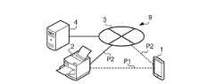
図1は、本実施形態に係る画像形成システム9の全体構成を示す図である。図1に示すように、画像形成システム9は、端末1と、画像形成装置2と、メールサーバ装置4と、これらを接続する通信回線3とを有する。1. Embodiment 1-1. Overall Configuration of Image Forming System FIG. 1 is a diagram showing an overall configuration of an
端末1は通信回線3に無線で接続され、画像形成装置2およびメールサーバ装置4は通信回線3に有線で接続されている。端末1と、画像形成装置2と、メールサーバ装置4とは、互いに通信回線3を介して情報を遣り取りする。 The
また、端末1と画像形成装置2とは、通信回線3を介さずに、直接無線で情報を遣り取りすることが可能なように構成されている。端末1と画像形成装置2とが、通信回線3を介さずに直接、無線で通信する通信路を「第1通信路P1」という。すなわち、第1通信路P1は、他の機器を経由しないで端末1と画像形成装置2とが接続する無線通信による通信路である。このような無線通信の技術としてWi−Fi DIRECT(登録商標)という通信方法が知られている。 Further, the
一方、端末1と画像形成装置2とが、通信回線3を介して通信する通信路を「第2通信路P2」という。なお、一般に、端末1と通信回線3との接続はアクセスポイント機器(図示略)により中継されており、通信回線3から画像形成装置2までの接続にはルーター機器(図示略)などが介在している。つまり、第2通信路P2は、通信回線3および複数の他の機器を経由した通信路である。 On the other hand, a communication path through which the
画像形成装置2は、端末1の指示を受付けてその指示に応じた画像を形成する出力装置である。なお、画像形成システム9において、端末1、画像形成装置2、およびメールサーバ装置4は、いずれも複数台が存在していてもよい。 The
1−2.端末の構成
図2は、本実施形態に係る端末1の構成を示す図である。制御部11は、CPU(Central Processing Unit)、ROM(Read Only Memory)、RAM(Random Access Memory)を有し、CPUがROMや記憶部12に記憶されているコンピュータプログラム(以下、単にプログラムという)を読み出して実行することにより端末1の各部を制御する。1-2. Terminal Configuration FIG. 2 is a diagram illustrating a configuration of the
第1通信部16は、例えばIEEE802.11規格に準拠した無線通信回路であり、画像形成装置2の第3通信部26と第1通信路P1を構成する。また、第1通信部16は、画像形成装置2から発信される標識信号(ビーコン)を受信する機能を有する。 The
第2通信部13は、例えばLTE(Long Term Evolution)などに準拠した無線通信回路であって、端末1を通信回線3に接続する。第2通信部13は、画像形成装置2の第4通信部23と第2通信路P2を構成する。 The
操作部14は各種の指示をするための操作ボタン等の操作子を備えており、ユーザによる操作を受付けてその操作内容に応じた信号を制御部11に供給する。操作部14は、画像形成装置2と第1通信路P1を確立するためのプッシュボタンを有していてもよい。 The
表示部15は、液晶ディスプレイを有しており、制御部11の制御の下、記憶部12に記憶されている情報などを表示する。また、表示部15は、操作部14とともにタッチパネルを構成してもよい。 The
記憶部12はソリッドステートドライブ等の大容量の記憶手段であり、制御部11のCPUに読み込まれるプログラムを記憶している。また、記憶部12は、自MACアドレス121を記憶しており、宛先情報122、接続情報123を記憶する領域を有する。 The
図3は、記憶部12の記憶内容を説明するための図である。自MACアドレス121は、端末1自身の物理アドレスを示す識別情報であり、ここではMACアドレス(Media Access Control address)である。 FIG. 3 is a diagram for explaining the stored contents of the
宛先情報122は、第1通信路P1を用いて接続した画像形成装置2から送信されるメールアドレスであって、その画像形成装置2を示すメールアドレスである。接続情報123は、第1通信路P1を用いて画像形成装置2と接続するときに必要となる各種の情報であり、例えば、第1通信路P1を識別するためのESS−ID(Extended Service Set Identifier:拡張サービスセット識別子)、第1通信路P1における役割(接続のオーナーであるか、クライアントであるかの別)、通信相手の物理アドレスである相手MACアドレス、暗号化された情報を前記第1通信路経由で通信するために必要なマスター鍵や一時利用鍵、鍵生成に用いるパスフレーズなどである。 The
1−3.画像形成装置の構成
図4は、本実施形態に係る画像形成装置2の構成を示す図である。制御部21は、CPU、ROM、RAMを有し、CPUがROMや記憶部22に記憶されているプログラムを読み出して実行することにより画像形成装置2の各部を制御する。1-3. Configuration of Image Forming Apparatus FIG. 4 is a diagram illustrating a configuration of the
第3通信部26は、例えばIEEE802.11規格に準拠した無線通信回路であり、端末1の第1通信部16と第1通信路P1を構成する。また、第3通信部26は、周囲に標識信号を発信する機能を有する。 The
第4通信部23は、画像形成装置2を通信回線3に接続する有線通信回路である。第4通信部23は、端末1の第2通信部13と第2通信路P2を構成する。なお、第4通信部23は、画像形成装置2を通信回線3に接続する無線通信回路であってもよい。 The
操作部24は各種の指示をするための操作ボタン等の操作子を備えており、ユーザによる操作を受付けてその操作内容に応じた信号を制御部21に供給する。操作部24は、端末1と第1通信路P1を確立するためのプッシュボタンを有していてもよい。 The
表示部25は、液晶ディスプレイを有しており、制御部21の制御の下、記憶部22に記憶されている情報などを表示する。また、表示部25は、操作部24とともにタッチパネルを構成してもよい。 The
画像形成部27は、制御部21の制御の下、電子写真方式により用紙などの媒体にトナーを定着させて画像を形成する。 The
記憶部22は、読み出し専用のROMと、書き換え可能なRAMとを有する。記憶部22のROMは、制御部21のCPUに読み込まれるプログラムや、自MACアドレス221、および宛先情報222を記憶している。記憶部22のRAMは、電源切断時に記憶内容が失われる記憶領域であり、接続情報列223を記憶する領域を含む。なお、記憶部22のROMは、EEPROM(Electrically Erasable Programmable Read-Only Memory)、フラッシュメモリ、ソリッドステートドライブなど書き換え可能であって電源切断後にも記憶内容を維持する記憶手段を含んでいてもよい。 The
図5は、記憶部22の記憶内容を説明するための図である。自MACアドレス221は、画像形成装置2自身の物理アドレスを示す識別情報であり、ここではMACアドレスである。 FIG. 5 is a diagram for explaining the stored contents of the
宛先情報222は、画像形成装置2が第2通信路P2を通じて情報を受信することを可能にするための識別情報であり、具体的には、画像形成装置2自身のメールアドレスである。この宛先情報222に記載されたメールアドレスを宛先としてメールを送信すると、そのメールは、第2通信路P2上にあるメールサーバ装置4のメールスプールに保管される。画像形成装置2は、例えば定期的にメールサーバ装置4により保管されているそれらのメールを自身宛のメールとして取り出す。この宛先情報222は、端末1と第1通信路P1によって接続されたときに、第1通信路P1によりその端末1へ送信される。宛先情報222を受信した端末1は、その内容を宛先情報122に記憶する。端末1は、記憶したこの宛先情報122を用いて、第2通信路P2経由で画像形成装置2にメールを送信する。 The
接続情報列223は、第1通信路P1を用いて複数の端末1とそれぞれ接続するときに必要となる接続情報を、相手である端末1ごとに配列した待ち行列である。図5に示す接続情報列223は、優先順位表2231と、接続情報2232とを有する。優先順位表2231は、画像形成装置2と複数の端末1との各接続を識別するESS−IDに、優先順位と、接続情報2232とを割り当てる。接続情報2232に記述された接続情報は、対応するESS−IDで識別される接続をするために、画像形成装置2が必要とする情報であり、第1通信路P1における役割と、相手MACアドレスとを除いて相手である端末1に記憶された接続情報と共通している。 The
例えば記憶部22のRAMにおいて記憶可能な領域が決められた閾値を下回ったとき、優先順位表2231に記述された優先順位の低いものから、対応する接続情報が削除される。また、画像形成装置2の電源が切断されたとき、記憶部22のRAMに記憶されていた接続情報列223は消去される。 For example, when the area that can be stored in the RAM of the
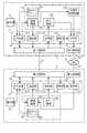
1−4.画像形成システムの機能的構成
図6は、画像形成システム9の機能的構成を示す図である。端末1の制御部11は、記憶部12に記憶されたプログラムを実行することにより、接続部111、取得部112、送信部113、生成部114、および検知部115として機能する。画像形成装置2の制御部21は、記憶部22に記憶されたプログラムを実行することにより、接続部211、供給部212、受信部213、生成部214、および検知部215として機能する。1-4. Functional Configuration of Image Forming System FIG. 6 is a diagram illustrating a functional configuration of the
生成部114は、操作部14の操作に応じて第1通信路P1により画像形成装置2と情報の遣り取りを開始し、第1通信路P1における画像形成装置2との接続に必要な接続情報123を生成する。生成された接続情報123は、記憶部12に記憶される。
接続部111は、接続情報123を用いて、無線通信による第1通信路P1において画像形成装置2と接続する。The
The
取得部112は、第1通信路P1を用いて画像形成装置2と接続したときにその画像形成装置2が使用した接続情報に対応付けて、画像形成装置2の識別情報である宛先情報222を取得する。取得部112は、取得した宛先情報222を宛先情報122として記憶部12に記憶する。 The
検知部115は、第1通信路P1による画像形成装置2との接続が切断されていることを検知する。検知部115は、例えば、第1通信部16を監視して、画像形成装置2との接続が切断されていることを検知する。 The
また、検知部115は、画像形成装置2から決められた期間にわたって第1通信路P1による接続のための応答がない場合に、画像形成装置2との接続が切断されていることを検知してもよい。具体的には、例えば、第1通信部16を監視した結果、画像形成装置2との接続が或る期間にわたってないと、検知部115は、画像形成装置2との接続が少なくとも一時的に切断されていると判断する。そして、このとき、検知部115は、接続部111に指示して画像形成装置2に対して接続のための要求をする。この要求に対して決められた期間にわたって応答を待った結果、応答がないときに、検知部115は、画像形成装置2との接続が切断されていることを検知すればよい。 In addition, the
送信部113は、第1通信路P1による画像形成装置2との接続が切断されていることが検知部115により検知されたときに、取得部112が取得した宛先情報122を用いて、その宛先情報122に対応する接続情報を第2通信路P2経由で画像形成装置2に送信する。このとき、送信部113が送信する接続情報は、図6に破線で示す通り、宛先情報122に対応する接続情報123と自MACアドレス121とから生成された装置用接続情報124であってもよい。 The
装置用接続情報124は、第1通信路P1で端末1と接続するときに画像形成装置2に用いられた接続情報2232と内容が同じものである。装置用接続情報124は、具体的には、接続情報123の「相手MACアドレス」を自MACアドレス121の記憶内容に、「役割」を相手方の情報にそれぞれ書き換えたものである。相手方の情報とは、例えば、接続情報123の「役割」が「クライアント」であるならば、「クライアント」ではなく「オーナー」である。 The
また、送信部113は、接続情報123と自MACアドレス121とを対応付けて画像形成装置2に送信してもよい。この場合、画像形成装置2が、受信した接続情報123と自MACアドレス121とから、接続情報列223に追加する接続情報2232を生成してもよい。 Further, the
生成部214は、操作部24の操作に応じて第1通信路P1により端末1と情報の遣り取りを開始し、第1通信路P1における端末1との接続に必要な接続情報2232を生成する。生成された接続情報2232は、優先順位表2231に含まれるESS−IDのいずれかと対応付けられて、接続情報列223に含められ、記憶部22に記憶される。 The
接続部211は、接続情報列223を用いて、無線通信による第1通信路P1において端末1と接続する。 The
供給部212は、第1通信路P1を用いて端末1と接続したときに画像形成装置2(自装置)が使用した接続情報2232に対応付けて、自装置の宛先情報222(識別情報)を端末1に供給する。 The
検知部215は、第1通信路P1による端末1との接続が切断されていることを検知する。検知部215は、例えば、第3通信部26を監視して、端末1との接続が切断されていることを検知する。 The
また、検知部215は、記憶部22を監視して画像形成装置2(自装置)から接続情報列223が失われている場合に、端末1との接続が切断されていることを検知してもよい。 The
受信部213は、第1通信路P1による端末1との接続が切断されているときに、供給部212が供給した宛先情報222を用いて、その宛先情報222に対応する接続情報を第2通信路P2経由で端末1から受信する。そして、受信部213は、端末1との接続が切断されていることが検知部215により検知されたときに、受信した接続情報を記憶部22の接続情報列223に記憶させる。 The receiving
1−5.画像形成システムの動作
(1)初回の接続の動作
図7は、画像形成システム9における初回の接続の動作を説明するためのシーケンス図である。端末1と画像形成装置2とを最初に接続するとき、画像形成システム9は、それぞれの操作部14、24を用いる。利用者は、端末1の操作部14に設けられたプッシュボタンを押下し(ステップS101)、決められた時間内(例えば数十秒)に画像形成装置2の操作部24に設けられたプッシュボタンを押下する(ステップS102)。1-5. Operation of Image Forming System (1) First Connection Operation FIG. 7 is a sequence diagram for explaining the first connection operation in the
なお、ステップS101と、ステップS102の順番は逆でもよい。このプッシュボタンによる初回接続は、互いの無線信号が届く距離に存在する2つの機器(端末1と画像形成装置2)を利用者が決められた時間内に操作して一対一の接続を確立させるため、安全性が高いとされている。 Note that the order of step S101 and step S102 may be reversed. In the initial connection by this push button, a user operates two devices (
また、初回接続には、いわゆるPIN(Personal Identification Number)コードを入力する方式が用いられてもよい。この方式は、接続させる2つの機器のうち、一方の機器が乱数などにより発生させたPINコードを、利用者が決められた時間内に他方の機器で入力することで接続を確立する方式である。 For the initial connection, a method of inputting a so-called PIN (Personal Identification Number) code may be used. This method is a method of establishing a connection by inputting a PIN code generated by one of the two devices to be connected using a random number or the like with the other device within a predetermined time. .
プッシュボタンが押下された端末1は、周囲に向けてプローブ要求(Probe Request)を送信する(ステップS103)。プローブ要求とは、接続を識別する識別情報を要求するもので、具体的にはESS−IDを要求する。端末1の周囲に存在していて、上述したプローブ要求を受取った画像形成装置2は、ESS−IDを含むプローブ応答(Probe Response)を端末1に向けて送信する(ステップS104)。 The
プローブ応答を受取った端末1は、これに基づいて接続のESS−IDを特定し、画像形成装置2に対して役割を交渉する要求(役割交渉要求:GO Negotiation Request)を送信する(ステップS105)。ここでは、画像形成装置2が接続のオーナーとなることが定められているため、この役割交渉要求を受取った画像形成装置2は、自身がオーナーとなる旨の応答(役割交渉応答:GO Negotiation Response)を端末1に送信する(ステップS106)。 The
役割交渉応答を受取った端末1は、自身がクライアントとなるように接続情報123を設定し、暗号化方式などに関する設定を画像形成装置2と交換する(ステップS107)。 The
次に、画像形成装置2は、第3通信部26から標識信号を発信し(ステップS108)、この標識信号を第1通信部16で受信した端末1は、画像形成装置2に自身を認証させるための認証要求を送信する(ステップS109)。認証要求を受信した画像形成装置2は、ステップS107で交換していた設定などを用いて、端末1との接続に対する認証を行い、認証結果を示す認証応答を端末1に送信する(ステップS110)。 Next, the
認証応答を受信した端末1は、認証結果が肯定的である場合に、画像形成装置2に向けてアソシエーション要求(Association Request)を送信する(ステップS111)。アソシエーション要求とは、第1通信路P1における暗号化された接続を確立する要求である。アソシエーション要求を受信した画像形成装置2は、これに応答する内容のアソシエーション応答(Association Response)を端末1に向けて送信する(ステップS112)。 The
そして、端末1および画像形成装置2は、4ウェイハンドシェイク(4-way handshake)と呼ばれる手続を経て(ステップS113)、互いに接続する。このとき、互いの接続に必要な接続情報がそれぞれ生成される。端末1は、生成した接続情報を、記憶部12に接続情報123として記憶する(ステップS114)。画像形成装置2は、生成した接続情報を、接続情報2232として接続情報列223に追加することで、記憶部22に記憶する(ステップS115)。ステップS114とステップS115の順序は逆でもよい。 Then, the
画像形成装置2は、生成した接続情報に対応付けて自装置の宛先情報222を端末1に供給する(ステップS116)。この宛先情報222を取得した端末1は、これを宛先情報122として記憶部12に記憶する(ステップS117)。 The
(2)二回目以降の接続の動作
図8は、画像形成システム9における二回目以降の接続の動作を説明するためのシーケンス図である。画像形成装置2において、利用者が操作部24を操作して電源をオフ(切断状態)にすると(ステップS201)、画像形成装置2の記憶部22のうち、接続情報列223の記憶は消去される。電源オフの後に利用者が画像形成装置2の操作部24を操作して電源をオン(電力供給状態)にしても(ステップS202)、電源オフより前に記憶されていた接続情報列223の内容は復元しない。(2) Second and subsequent connection operations FIG. 8 is a sequence diagram for explaining the second and subsequent connection operations in the
端末1は、画像形成装置2の電源オフにより第1通信路P1による画像形成装置2との接続が少なくとも一時的に切断されていることを検知している。このとき端末1は、周囲に向けてプローブ要求を送信する(ステップS203)。端末1の周囲に存在していて、上述したプローブ要求を受取った画像形成装置2は、ESS−IDを含むプローブ応答を端末1に向けて送信する(ステップS204)。 The
プローブ応答を受取った端末1は、これに基づいて接続のESS−IDを特定し、特定したESS−IDが以前の接続に使われていたものであると判定すると、プローブ応答を送信した画像形成装置2に向けてインビテーション要求(Invitation Request)を送信する(ステップS205)。インビテーション要求とは、既に確立された接続(接続グループという)へ招待するものであり、対象とする機器に対してその接続グループへの参加を要求するものである。 The
インビテーション要求を受信した画像形成装置2は、招待された接続グループを記憶部22の接続情報列223から探すが、電源オフに伴ってそれ以前の接続情報列223の記憶内容が失われているため、インビテーション要求に対して応答しない。端末1は、インビテーション要求をしてから決められた時間が経過したか否かを判定するタイムアウト判定をする(ステップS206)。 The
端末1は、インビテーション要求をしてから決められた時間が経過したと判定すると、第1通信路P1による画像形成装置2との接続が切断されていると判断し、ステップS117で記憶した宛先情報122を用いて、その宛先情報122に対応する接続情報を第2通信路P2経由で画像形成装置2に送信する(ステップS207)。この宛先情報122は、具体的には画像形成装置2のメールアドレスであり、この送信は接続情報を含むメールの送信である。 If the
端末1から第2通信路P2経由で送信されたメールは、メールサーバ装置4(図1参照)のメールスプールに保存され、例えば定期的に画像形成装置2がメールスプールの中から自装置に向けて送信されたメールを抽出することにより、画像形成装置2に届く。 The mail transmitted from the
メールを取得した画像形成装置2は、そのメールに含まれている接続情報を、接続情報列223に追加して記憶する(ステップS208)。 The
端末1は、メールを送信した後、インビテーション要求を画像形成装置2に向けて再送する(ステップS209)。このインビテーション要求を再び受信した画像形成装置2は、接続情報を記憶しているため、これに応答する内容のインビテーション応答(Invitation Response)を送信する(ステップS210)。これにより、初回の接続で設定されたそれぞれの役割や暗号化方式などに関する設定が、端末1と画像形成装置2とで共有される。 After transmitting the mail, the
次に、画像形成装置2は、第3通信部26から標識信号を発信し(ステップS211)、この標識信号を第1通信部16で受信した端末1は、画像形成装置2に自身を認証させるための認証要求を送信する(ステップS212)。認証要求を受信した画像形成装置2は、ステップS210のインビテーション応答までに共有した設定などを用いて、端末1との接続に対する認証を行い、認証結果を示す認証応答を端末1に送信する(ステップS213)。 Next, the
認証応答を受信した端末1は、認証結果が肯定的である場合に、画像形成装置2に向けてアソシエーション要求を送信する(ステップS214)。アソシエーション要求を受信した画像形成装置2は、これに応答する(ステップS215)。そして、端末1および画像形成装置2は、4ウェイハンドシェイクを経て(ステップS216)、互いに接続する。 The
以上、説明した動作により、初回の接続で、プッシュボタンの押下などの操作を利用者が一度行えば、端末1と画像形成装置2とは第1通信路P1により接続され、その接続が切断された後で二回目以降の接続の際に利用者が別段の操作を行う必要がなくなるので、利用者の操作負担が軽減され、利便性が向上する。また、上述した端末1や画像形成装置2には、NFCなどの特別なデバイスを搭載する必要がない。 As described above, when the user performs an operation such as pressing a push button once for the first connection, the
2.変形例
以上が実施形態の説明であるが、この実施形態の内容は以下のように変形し得る。また、以下の変形例を組合せてもよい。2. Modification The above is the description of the embodiment, but the contents of this embodiment can be modified as follows. Further, the following modifications may be combined.
2−1.変形例1
上述した実施形態において、端末1は、インビテーション要求をしてから決められた時間が経過したと判定すると、第1通信路P1による画像形成装置2との接続が切断されていると判断し、宛先情報122を用いて接続情報を第2通信路P2経由で画像形成装置2に送信していたが、時間の経過を判定せずに上記の接続情報を送信してもよい。2-1.
In the above-described embodiment, when the
図9は、この変形例における画像形成システム9の、二回目以降の接続の動作を説明するためのシーケンス図である。図9におけるステップS301からステップS304までの動作は、図8におけるステップS201からステップS204までの動作と共通する内容である。 FIG. 9 is a sequence diagram for explaining the second and subsequent connection operations of the
ここで端末1は、ステップS205のインビテーション要求を送信する代わりに、記憶部12の宛先情報122を参照し、画像形成装置2の宛先情報が記述されているか否かを判定する(ステップS306)。そして、宛先情報122に画像形成装置2の宛先情報が記述されていると判定する場合に、宛先情報122を用いて、その宛先情報122に対応する接続情報を第2通信路P2経由で画像形成装置2に送信する(ステップS307)。 Here, instead of transmitting the invitation request in step S205, the
ステップS307に続くステップS308からステップS316までの動作は、図8におけるステップS208からステップS216までの動作と共通する内容である。この動作により、第1通信路P1による端末1と画像形成装置2との接続は、二回目以降の際に利用者が別段の操作を行う必要がなく、利用者の操作負担が軽減され、利便性が向上する。また、タイムアウト判定にかかる時間が不要となるため、全体の工程が短縮される。 The operations from step S308 to step S316 following step S307 are the same as the operations from step S208 to step S216 in FIG. With this operation, the connection between the terminal 1 and the
2−2.変形例2
図1に示した画像形成装置2は画像形成部27を有していたが、他の画像形成装置に画像形成の指示を送るインターフェイスを有していてもよい。この場合、画像形成装置2は、画像形成部27を有していない処理装置であってもよい。さらに、この処理装置が実行する処理は画像形成に限られない。処理装置は、例えば、端末1の指示に応じて、媒体などに形成された画像を読み取る処理を実行してもよい。2-2.
The
なお、画像形成システム9から上述した「他の画像形成装置」を除いた部分は、端末1と、その端末1から処理の指示を受付けてその指示に応じて処理を実行する処理装置とを有する処理システムとして解釈される。 The portion excluding the above-mentioned “other image forming apparatus” from the
2−3.変形例3
上述した実施例では、画像形成装置2(処理装置)の宛先情報222(識別情報)としてメールアドレスを例示したが、処理装置の識別情報はこれに限定されることはなく、処理装置の第2通信路におけるアドレス情報であってもよい。処理装置の識別情報は、例えば、TCP(Transmission Control Protocol)/IP(Internet Protocol)で用いられるIPアドレスであってもよいし、HTTP(Hyper Text Transfer Protocol)で用いられるURL(Uniform Resource Locator)であってもよい。端末は、これらの通信プロトコルを利用して、上述したアドレス情報により特定される処理装置に対して第2通信路経由で接続情報を転送するようにしてもよい。2-3.
In the above-described embodiment, the mail address is exemplified as the destination information 222 (identification information) of the image forming apparatus 2 (processing apparatus). However, the identification information of the processing apparatus is not limited to this, and the second information of the processing apparatus. Address information on the communication path may be used. The identification information of the processing device may be, for example, an IP address used in TCP (Transmission Control Protocol) / IP (Internet Protocol), or a URL (Uniform Resource Locator) used in HTTP (Hyper Text Transfer Protocol). There may be. The terminal may transfer the connection information via the second communication path to the processing device specified by the address information described above using these communication protocols.
2−4.変形例4
端末1の制御部11や画像形成装置2の制御部21によって実行されるプログラムは、磁気テープや磁気ディスクなどの磁気記録媒体、光ディスクなどの光記録媒体、光磁気記録媒体、半導体メモリなどの、コンピュータ装置が読み取り可能な記録媒体に記憶された状態で提供し得る。また、これらのプログラムを、インターネットなどを経由してダウンロードさせることも可能である。なお、上記の制御部11、制御部21によって例示した制御手段としてはCPU以外にも種々の装置が適用される場合があり、例えば、専用のプロセッサなどが用いられる。2-4.
A program executed by the
1…端末、11…制御部、111…接続部、112…取得部、113…送信部、114…生成部、12…記憶部、121…自MACアドレス、122…宛先情報、123…接続情報、124…装置用接続情報、13…第2通信部、14…操作部、15…表示部、16…第1通信部、2…画像形成装置、21…制御部、211…接続部、212…供給部、213…受信部、214…生成部、22…記憶部、221…自MACアドレス、222…宛先情報、223…接続情報列、2231…優先順位表、2232…接続情報、23…第4通信部、24…操作部、25…表示部、26…第3通信部、27…画像形成部、3…通信回線、4…メールサーバ装置、9…画像形成システム、P1…第1通信路、P2…第2通信路。DESCRIPTION OF
Claims (15)
Translated fromJapanese前記第1通信路において接続した前記処理装置の識別情報を取得する取得手段と、
前記第1通信路において前記接続情報と前記識別情報とを対応づけて記憶する記憶手段と、
前記第1通信路による前記処理装置との接続が切断されていることを検知する検知手段と、
前記検知手段により前記処理装置との前記接続が切断されていることが検知されたときに、前記記憶手段に記憶した前記接続情報と前記識別情報とを用いて、該処理装置が自端末と接続したときに使用した接続情報を前記第1通信路とは異なる第2通信路経由で該処理装置に送信する送信手段と、
を有することを特徴とする端末。Connection means for connecting to the processing device using the connection information in the first communication path by wireless communication;
Obtaining means for obtaining identification information of the processing device connected in the first communication path;
Storage means for storing the connection information and the identification information in association with each other in the first communication path;
Detecting means for detecting that the connection with the processing device via the first communication path is disconnected;
When the detection unit detects that the connection with the processing device is disconnected, the processing device is connected to its own terminal using the connection information and the identification information stored in the storage unit. Transmitting means for transmitting the connection information used at the time to the processing device via a second communication path different from the first communication path;
A terminal characterized by comprising:
前記送信手段は、前記接続情報を含むメールを前記処理装置に送信する
ことを特徴とする請求項1に記載の端末。The identification information is an email address,
The terminal according to claim 1, wherein the transmission unit transmits a mail including the connection information to the processing device.
前記送信手段は、TCP(Transmission Control Protocol)/IPを用いて前記接続情報を前記処理装置に送信する
ことを特徴とする請求項1に記載の端末。The identification information is an IP (Internet Protocol) address,
The terminal according to claim 1, wherein the transmission unit transmits the connection information to the processing device using TCP (Transmission Control Protocol) / IP.
前記送信手段は、HTTP(Hyper Text Transfer Protocol)を用いて前記接続情報を前記処理装置に送信する
ことを特徴とする請求項1に記載の端末。The identification information is a URL (Uniform Resource Locator),
The terminal according to claim 1, wherein the transmission unit transmits the connection information to the processing device using HTTP (Hyper Text Transfer Protocol).
ことを特徴とする請求項1から4のいずれか1項に記載の端末。The connection means includes key information indicating a key for communicating encrypted information via the first communication path, and a passphrase used to generate the key. The terminal according to any one of 1 to 4.
ことを特徴とする請求項1から5のいずれか1項に記載の端末。The detection means detects that the connection with the processing device is disconnected when there is no response for connection through the first communication path over a period determined by the processing device. The terminal according to any one of claims 1 to 5.
前記第1通信路において接続した前記端末に自装置の識別情報を供給する供給手段と、
前記第1通信路による前記端末との接続が切断されているときに、前記接続情報を前記第1通信路とは異なる第2通信路経由で該端末から受信する受信手段と、を備え、
前記接続手段は、前記受信した前記接続情報を用いて前記端末と接続する
ことを特徴とする処理装置。Connection means for connecting to the terminal using connection information in the first communication path by wireless communication;
Supply means for supplying identification information of the device to the terminal connected in the first communication path;
Receiving means for receiving the connection information from the terminal via a second communication path different from the first communication path when the connection with the terminal via the first communication path is disconnected;
The processing device is characterized in that the connection means connects to the terminal using the received connection information.
前記受信手段は、前記接続情報を含むメールを前記端末から受信する
ことを特徴とする請求項7に記載の処理装置。The identification information is an email address,
The processing apparatus according to claim 7, wherein the receiving unit receives a mail including the connection information from the terminal.
前記受信手段は、TCP(Transmission Control Protocol)/IPを用いて前記接続情報を前記端末から受信する
ことを特徴とする請求項7に記載の処理装置。The identification information is an IP (Internet Protocol) address,
The processing apparatus according to claim 7, wherein the receiving unit receives the connection information from the terminal using TCP (Transmission Control Protocol) / IP.
前記受信手段は、HTTP(Hyper Text Transfer Protocol)を用いて前記接続情報を前記端末から受信する
ことを特徴とする請求項7に記載の処理装置。The identification information is a URL (Uniform Resource Locator),
The processing apparatus according to claim 7, wherein the receiving unit receives the connection information from the terminal using HTTP (Hyper Text Transfer Protocol).
前記受信手段は、前記検知手段により前記接続が切断されていることが検知されたときに、受信した接続情報を前記記憶手段に記憶させ、
前記接続手段は、前記記憶手段に記憶された接続情報を使用して、前記第1通信路において端末と接続する
ことを特徴とする請求項7から10のいずれか1項に記載の処理装置。When the connection information stored in the storage unit of the device itself is lost, the detection unit detects a disconnection with the terminal,
The receiving unit stores the received connection information in the storage unit when the detecting unit detects that the connection is disconnected,
The processing device according to any one of claims 7 to 10, wherein the connection unit connects to a terminal in the first communication path using connection information stored in the storage unit.
前記受付手段が受付けた指示に応じて前記処理を実行する実行手段と、
を有することを特徴とする請求項7から11のいずれか1項に記載の処理装置。Receiving means for receiving a processing instruction from the terminal when connected to the terminal by the connecting means;
Execution means for executing the process in response to an instruction received by the reception means;
The processing apparatus according to claim 7, further comprising:
前記端末は、
無線通信による第1通信路において第1接続情報を使用して処理装置と接続する第1接続手段と、
前記第1通信路において接続した前記処理装置の識別情報を取得する取得手段と、
前記第1通信路において前記第1接続情報と前記識別情報とを対応づけて記憶する記憶手段と、
前記第1通信路による前記処理装置との接続が切断されていることを検知する検知手段と、
前記検知手段により前記処理装置との前記接続が切断されていることが検知されたときに、前記記憶手段に記憶した前記第1接続情報と前記識別情報とを用いて、該処理装置が自端末と接続したときに使用した第2接続情報を前記第1通信路とは異なる第2通信路経由で該処理装置に送信する送信手段と、
を有し、
前記処理装置は、
無線通信による前記第1通信路において前記第2接続情報を使用して前記端末と接続する第2接続手段と、
前記第1通信路において接続した前記端末に自装置の識別情報を供給する供給手段と、
前記第1通信路による前記端末との接続が切断されているときに、前記第2接続情報を前記第2通信路経由で該端末から受信する受信手段と、
前記第2接続手段により前記端末と接続しているときに、該端末から処理の指示を受付ける受付手段と、
前記受付手段が受付けた指示に応じて前記処理を実行する実行手段と、
を有し、
前記第2接続手段は、前記受信手段により受信した前記第2接続情報を用いて前記端末と接続する
ことを特徴とする処理システム。A processing system having a terminal and a processing device,
The terminal
First connection means for connecting to the processing device using the first connection information in the first communication path by wireless communication;
Obtaining means for obtaining identification information of the processing device connected in the first communication path;
Storage means for storing the first connection information and the identification information in association with each other in the first communication path;
Detecting means for detecting that the connection with the processing device via the first communication path is disconnected;
When the detection unit detects that the connection with the processing device is disconnected, the processing device uses the first connection information and the identification information stored in the storage unit, Transmitting means for transmitting the second connection information used at the time of connection to the processing device via a second communication path different from the first communication path;
Have
The processor is
Second connection means for connecting to the terminal using the second connection information in the first communication path by wireless communication;
Supply means for supplying identification information of the device to the terminal connected in the first communication path;
Receiving means for receiving the second connection information from the terminal via the second communication path when the connection with the terminal via the first communication path is disconnected;
Receiving means for receiving a processing instruction from the terminal when connected to the terminal by the second connecting means;
Execution means for executing the process in response to an instruction received by the reception means;
Have
The second connection means connects to the terminal using the second connection information received by the receiving means.
無線通信による第1通信路において接続情報を使用して処理装置と接続する接続手段と、
前記第1通信路において接続した前記処理装置の識別情報を取得する取得手段と、
前記第1通信路において前記接続情報と前記識別情報とを対応づけて記憶する記憶手段と、
前記第1通信路による前記処理装置との接続が切断されていることを検知する検知手段と、
前記検知手段により前記処理装置との前記接続が切断されていることが検知されたときに、前記記憶手段に記憶した前記接続情報と前記識別情報とを用いて、該処理装置が自端末と接続したときに使用した接続情報を前記第1通信路とは異なる第2通信路経由で該処理装置に送信する送信手段
として機能させるためのプログラム。Computer
Connection means for connecting to the processing device using the connection information in the first communication path by wireless communication;
Obtaining means for obtaining identification information of the processing device connected in the first communication path;
Storage means for storing the connection information and the identification information in association with each other in the first communication path;
Detecting means for detecting that the connection with the processing device via the first communication path is disconnected;
When the detection unit detects that the connection with the processing device is disconnected, the processing device is connected to its own terminal using the connection information and the identification information stored in the storage unit. A program for functioning as transmission means for transmitting connection information used at the time of transmission to the processing device via a second communication path different from the first communication path.
無線通信による第1通信路において接続情報を使用して端末と接続する接続手段と、
前記第1通信路において接続した前記端末に自装置の識別情報を供給する供給手段と、
前記第1通信路による前記端末との接続が切断されているときに、前記接続情報を前記第1通信路とは異なる第2通信路経由で該端末から受信する受信手段
として機能させるとともに、
前記接続手段が、前記受信した前記接続情報を用いて前記端末と接続する
ように機能させるためのプログラム。Computer
Connection means for connecting to the terminal using connection information in the first communication path by wireless communication;
Supply means for supplying identification information of the device to the terminal connected in the first communication path;
When the connection with the terminal via the first communication path is cut off, the connection information is received from the terminal via a second communication path different from the first communication path,
A program for causing the connection means to function to connect to the terminal using the received connection information.
Priority Applications (3)
| Application Number | Priority Date | Filing Date | Title |
|---|---|---|---|
| JP2015061407AJP6485153B2 (en) | 2015-03-24 | 2015-03-24 | Terminal, processing device, processing system, and program |
| US14/832,141US10368237B2 (en) | 2015-03-24 | 2015-08-21 | Terminal, processing apparatus, processing system, and non-transitory computer readable medium |
| CN201510648452.5ACN106028466B (en) | 2015-03-24 | 2015-10-09 | Terminal, processing device, processing system and processing method |
Applications Claiming Priority (1)
| Application Number | Priority Date | Filing Date | Title |
|---|---|---|---|
| JP2015061407AJP6485153B2 (en) | 2015-03-24 | 2015-03-24 | Terminal, processing device, processing system, and program |
Publications (2)
| Publication Number | Publication Date |
|---|---|
| JP2016181826Atrue JP2016181826A (en) | 2016-10-13 |
| JP6485153B2 JP6485153B2 (en) | 2019-03-20 |
Family
ID=56976364
Family Applications (1)
| Application Number | Title | Priority Date | Filing Date |
|---|---|---|---|
| JP2015061407AActiveJP6485153B2 (en) | 2015-03-24 | 2015-03-24 | Terminal, processing device, processing system, and program |
Country Status (3)
| Country | Link |
|---|---|
| US (1) | US10368237B2 (en) |
| JP (1) | JP6485153B2 (en) |
| CN (1) | CN106028466B (en) |
Families Citing this family (3)
| Publication number | Priority date | Publication date | Assignee | Title |
|---|---|---|---|---|
| CN109495982B (en)* | 2018-12-14 | 2020-12-18 | 锐迪科微电子科技(上海)有限公司 | Communication method and device and readable storage medium |
| JP2020188426A (en)* | 2019-05-17 | 2020-11-19 | 富士ゼロックス株式会社 | System and program |
| JP7115498B2 (en)* | 2020-03-17 | 2022-08-09 | カシオ計算機株式会社 | Wireless communication device, terminal device, wireless communication system, communication connection control method and program |
Citations (2)
| Publication number | Priority date | Publication date | Assignee | Title |
|---|---|---|---|---|
| JP2009171409A (en)* | 2008-01-18 | 2009-07-30 | Panasonic Corp | Wireless communication terminal and wireless communication method |
| JP2010263438A (en)* | 2009-05-07 | 2010-11-18 | Fujitsu Ltd | Communication server device, communication terminal device, and communication method |
Family Cites Families (18)
| Publication number | Priority date | Publication date | Assignee | Title |
|---|---|---|---|---|
| KR20030047874A (en)* | 2000-03-03 | 2003-06-18 | 퀄컴 인코포레이티드 | Method and apparatus for participating in group communication services in an existing communication system |
| EP1635508A1 (en) | 2004-09-08 | 2006-03-15 | Koninklijke Philips Electronics N.V. | Secure pairing for wireless communications devices |
| US8352323B2 (en)* | 2007-11-30 | 2013-01-08 | Blaze Mobile, Inc. | Conducting an online payment transaction using an NFC enabled mobile communication device |
| JP2007202001A (en)* | 2006-01-30 | 2007-08-09 | Kyocera Corp | Mobile communication device and control method thereof |
| WO2008124795A1 (en)* | 2007-04-10 | 2008-10-16 | Marvell Semiconductor, Inc. | Apparatuses, systems, software and methods for wireless interaction with vehicle control systems |
| US8175079B2 (en)* | 2009-03-27 | 2012-05-08 | Motorola Solutions, Inc. | Device and method for reestablishing a wireless connection in a wireless network |
| US9021084B2 (en)* | 2009-10-22 | 2015-04-28 | Xerox Corporation | Network device discovery |
| JP5126269B2 (en) | 2010-03-26 | 2013-01-23 | ブラザー工業株式会社 | Wireless communication device |
| EP2755385B1 (en)* | 2011-09-09 | 2016-11-02 | Olympus Corporation | Wireless video transmission system and transmission device |
| MY165315A (en)* | 2012-03-26 | 2018-03-21 | Nextwave Tech Sdn Bhd | Method of seamless policy based network discovery, selection and switching |
| US20140013100A1 (en)* | 2012-07-05 | 2014-01-09 | Martin M. Menzel | Establish bidirectional wireless communication between electronic devices using visual codes |
| US20140156375A1 (en)* | 2012-12-04 | 2014-06-05 | CCE Credit Card Enterprises, Inc. | Systems and methods for processing coupons over a payment processing network |
| JP2014158255A (en)* | 2013-01-16 | 2014-08-28 | Ricoh Co Ltd | Radio communication apparatus, radio communication method, and program |
| US9125236B2 (en)* | 2013-06-07 | 2015-09-01 | Apple Inc. | Method and apparatus for cooperative channel switching |
| WO2015060876A1 (en)* | 2013-10-25 | 2015-04-30 | Empire Technology Development, Llc | Secure connection for wireless devices via network records |
| US20150163841A1 (en)* | 2013-12-11 | 2015-06-11 | Lenovo (Beijing) Co., Ltd. | Method for processing information and electronic apparatus |
| CN103686586B (en) | 2013-12-11 | 2017-03-01 | 联想(北京)有限公司 | A kind of information processing method and electronic equipment |
| US9794783B2 (en)* | 2015-01-16 | 2017-10-17 | Jeffrey Huang | Machine-to-machine visual code generation and recognition method and system for device communications |
- 2015
- 2015-03-24JPJP2015061407Apatent/JP6485153B2/enactiveActive
- 2015-08-21USUS14/832,141patent/US10368237B2/enactiveActive
- 2015-10-09CNCN201510648452.5Apatent/CN106028466B/enactiveActive
Patent Citations (2)
| Publication number | Priority date | Publication date | Assignee | Title |
|---|---|---|---|---|
| JP2009171409A (en)* | 2008-01-18 | 2009-07-30 | Panasonic Corp | Wireless communication terminal and wireless communication method |
| JP2010263438A (en)* | 2009-05-07 | 2010-11-18 | Fujitsu Ltd | Communication server device, communication terminal device, and communication method |
Also Published As
| Publication number | Publication date |
|---|---|
| CN106028466A (en) | 2016-10-12 |
| CN106028466B (en) | 2019-08-09 |
| US10368237B2 (en) | 2019-07-30 |
| JP6485153B2 (en) | 2019-03-20 |
| US20160286530A1 (en) | 2016-09-29 |
Similar Documents
| Publication | Publication Date | Title |
|---|---|---|
| US11709639B2 (en) | Non-transitory computer-readable medium storing computer-readable instructions for terminal device and terminal device | |
| US10547468B2 (en) | Communication apparatus, communication method, and storage medium | |
| KR102060547B1 (en) | Method and apparatus for registering wireless device in wireless communication system | |
| US7317712B2 (en) | Wireless communication system, communication device, communication controlling method, and communication control program | |
| US20180069851A1 (en) | Communication apparatus, communication method, and storage medium | |
| JP6584186B2 (en) | COMMUNICATION DEVICE, COMMUNICATION METHOD, AND PROGRAM | |
| CN102833752B (en) | Wireless communication device | |
| WO2018121234A1 (en) | Method, device and system for establishing communication connection | |
| CN108292199B (en) | Information processing apparatus, information processing system, and information processing method | |
| US10425809B2 (en) | Communication apparatus, method for controlling communication apparatus, and program | |
| JP6480677B2 (en) | COMMUNICATION DEVICE, ITS CONTROL METHOD, COMPUTER PROGRAM | |
| KR20190032845A (en) | Electronic device for performing reconnection of near field communication and method for controlling thereof | |
| JP6335629B2 (en) | Communication apparatus, control method, and program | |
| KR20070080197A (en) | Multiple network connection method and communication device thereof | |
| US10575341B2 (en) | Communication system and recording medium | |
| US10237903B2 (en) | Remote maintenance system | |
| CN103974375A (en) | Wireless network access method, device and system | |
| JP6485153B2 (en) | Terminal, processing device, processing system, and program | |
| KR20200002742A (en) | Method and apparatus for registering wireless device in wireless communication system | |
| JP6512875B2 (en) | Communication device, control method of communication device, and program | |
| CN109565892B (en) | Communication device, communication method and computer readable storage medium | |
| JP2016015081A (en) | COMMUNICATION TERMINAL DEVICE, COMMUNICATION SYSTEM, PROGRAM, AND COMMUNICATION TERMINAL DEVICE CONTROL METHOD | |
| JP7196248B2 (en) | Communication device, control method and program | |
| JP2010050580A (en) | Wireless communication system | |
| JP6702407B2 (en) | Communication terminal device, communication system, program, and communication terminal device control method |
Legal Events
| Date | Code | Title | Description |
|---|---|---|---|
| A621 | Written request for application examination | Free format text:JAPANESE INTERMEDIATE CODE: A621 Effective date:20180228 | |
| A977 | Report on retrieval | Free format text:JAPANESE INTERMEDIATE CODE: A971007 Effective date:20181031 | |
| A131 | Notification of reasons for refusal | Free format text:JAPANESE INTERMEDIATE CODE: A131 Effective date:20181113 | |
| A521 | Request for written amendment filed | Free format text:JAPANESE INTERMEDIATE CODE: A523 Effective date:20190109 | |
| TRDD | Decision of grant or rejection written | ||
| A01 | Written decision to grant a patent or to grant a registration (utility model) | Free format text:JAPANESE INTERMEDIATE CODE: A01 Effective date:20190122 | |
| A61 | First payment of annual fees (during grant procedure) | Free format text:JAPANESE INTERMEDIATE CODE: A61 Effective date:20190204 | |
| R150 | Certificate of patent or registration of utility model | Ref document number:6485153 Country of ref document:JP Free format text:JAPANESE INTERMEDIATE CODE: R150 | |
| S533 | Written request for registration of change of name | Free format text:JAPANESE INTERMEDIATE CODE: R313533 | |
| R350 | Written notification of registration of transfer | Free format text:JAPANESE INTERMEDIATE CODE: R350 |