JP2016170301A - Projector - Google Patents
ProjectorDownload PDFInfo
- Publication number
- JP2016170301A JP2016170301AJP2015050507AJP2015050507AJP2016170301AJP 2016170301 AJP2016170301 AJP 2016170301AJP 2015050507 AJP2015050507 AJP 2015050507AJP 2015050507 AJP2015050507 AJP 2015050507AJP 2016170301 AJP2016170301 AJP 2016170301A
- Authority
- JP
- Japan
- Prior art keywords
- light
- color
- separation layer
- color separation
- incident
- Prior art date
- Legal status (The legal status is an assumption and is not a legal conclusion. Google has not performed a legal analysis and makes no representation as to the accuracy of the status listed.)
- Pending
Links
- 238000000926separation methodMethods0.000claimsabstractdescription370
- 230000003287optical effectEffects0.000claimsabstractdescription51
- 230000010287polarizationEffects0.000claimsdescription70
- 238000006243chemical reactionMethods0.000claimsdescription21
- 239000007787solidSubstances0.000claimsdescription21
- OAICVXFJPJFONN-UHFFFAOYSA-NPhosphorusChemical compound[P]OAICVXFJPJFONN-UHFFFAOYSA-N0.000claimsdescription20
- 238000005286illuminationMethods0.000description44
- 238000010586diagramMethods0.000description10
- 230000000694effectsEffects0.000description8
- 230000005284excitationEffects0.000description8
- 230000005540biological transmissionEffects0.000description5
- 238000002834transmittanceMethods0.000description4
- 239000004973liquid crystal related substanceSubstances0.000description3
- 239000000463materialSubstances0.000description2
- 239000011159matrix materialSubstances0.000description2
- 238000000034methodMethods0.000description2
- 230000004048modificationEffects0.000description2
- 238000012986modificationMethods0.000description2
- 230000008569processEffects0.000description2
- VYPSYNLAJGMNEJ-UHFFFAOYSA-NSilicium dioxideChemical compoundO=[Si]=OVYPSYNLAJGMNEJ-UHFFFAOYSA-N0.000description1
- 230000008901benefitEffects0.000description1
- 230000015572biosynthetic processEffects0.000description1
- 239000011248coating agentSubstances0.000description1
- 238000000576coating methodMethods0.000description1
- 239000003086colorantSubstances0.000description1
- 238000001816coolingMethods0.000description1
- 239000013078crystalSubstances0.000description1
- 230000006866deteriorationEffects0.000description1
- 239000005304optical glassSubstances0.000description1
- 239000011347resinSubstances0.000description1
- 229920005989resinPolymers0.000description1
- 229910052594sapphireInorganic materials0.000description1
- 239000010980sapphireSubstances0.000description1
- 239000000758substrateSubstances0.000description1
- 238000003786synthesis reactionMethods0.000description1
- 230000002194synthesizing effectEffects0.000description1
- 230000009466transformationEffects0.000description1
Images


Classifications
- G—PHYSICS
- G03—PHOTOGRAPHY; CINEMATOGRAPHY; ANALOGOUS TECHNIQUES USING WAVES OTHER THAN OPTICAL WAVES; ELECTROGRAPHY; HOLOGRAPHY
- G03B—APPARATUS OR ARRANGEMENTS FOR TAKING PHOTOGRAPHS OR FOR PROJECTING OR VIEWING THEM; APPARATUS OR ARRANGEMENTS EMPLOYING ANALOGOUS TECHNIQUES USING WAVES OTHER THAN OPTICAL WAVES; ACCESSORIES THEREFOR
- G03B21/00—Projectors or projection-type viewers; Accessories therefor
- G03B21/14—Details
- H—ELECTRICITY
- H04—ELECTRIC COMMUNICATION TECHNIQUE
- H04N—PICTORIAL COMMUNICATION, e.g. TELEVISION
- H04N9/00—Details of colour television systems
- H04N9/12—Picture reproducers
- H04N9/31—Projection devices for colour picture display, e.g. using electronic spatial light modulators [ESLM]
Landscapes
- Physics & Mathematics (AREA)
- General Physics & Mathematics (AREA)
- Engineering & Computer Science (AREA)
- Multimedia (AREA)
- Signal Processing (AREA)
- Projection Apparatus (AREA)
- Video Image Reproduction Devices For Color Tv Systems (AREA)
Abstract
Description
Translated fromJapanese本発明は、プロジェクターに関する。 The present invention relates to a projector.
従来、光源と、当該光源から出射された光を変調して画像情報に応じた画像を形成する光変調装置と、形成された画像をスクリーン等の被投射面上に拡大投射する投射光学装置と、を備えたプロジェクターが知られている。このようなプロジェクターとして、光源から出射された光から赤、緑及び青の色光を分離するとともに、各色光に応じて設けられた光変調装置による各色光の変調光を合成する1つの3色性プリズム・アセンブリを備えたものが知られている(例えば、特許文献1参照)。 Conventionally, a light source, a light modulation device that modulates light emitted from the light source to form an image according to image information, and a projection optical device that enlarges and projects the formed image onto a projection surface such as a screen Are known. As such a projector, one trichromaticity which separates red, green and blue color lights from light emitted from a light source and synthesizes modulated light of each color light by a light modulation device provided according to each color light. One having a prism assembly is known (for example, see Patent Document 1).
この特許文献1に記載のプロジェクター(投射装置)は、光源と、当該光源から出射された光のうち、p偏光を透過し、s偏光を反射させるPBSと、3つのプリズム及び2つの2色性皮膜を有するプリズム・アセンブリと、光変調装置としての3つの反射型ライトバルブと、投射光学装置と、を備える。
このプロジェクターでは、プリズム・アセンブリの各2色性皮膜により、PBSにて反射されたs偏光から赤、緑及び青の色光が分離され、これら色光は、それぞれ対応する反射型ライトバルブに入射されて変調される。そして、当該反射型ライトバルブにより変調されてp偏光となった各色光は、プリズム・アセンブリに再度入射され、当該プリズム・アセンブリにて合成されて、PBSに入射される。これら色光は、PBSを通過して投射光学装置に入射され、当該投射光学装置によって投射される。The projector (projection apparatus) described in Patent Document 1 includes a light source, a PBS that transmits p-polarized light and reflects s-polarized light out of the light emitted from the light source, three prisms, and two dichroic properties. A prism assembly having a coating, three reflective light valves as light modulation devices, and a projection optical device are provided.
In this projector, each dichroic film of the prism assembly separates red, green, and blue color light from the s-polarized light reflected by the PBS, and these color lights are respectively incident on the corresponding reflective light valves. Modulated. Then, each color light that has been modulated by the reflective light valve to become p-polarized light is incident again on the prism assembly, is synthesized by the prism assembly, and is incident on the PBS. These colored lights pass through the PBS, enter the projection optical apparatus, and are projected by the projection optical apparatus.
ところで、上記2色性皮膜である色分離層は、当該色分離層に入射される光の入射角が大きくなると、p偏光での色分離特性とs偏光での色分離特性との乖離が大きくなる。具体的に、光の入射角(色分離層の法線に対する光の角度)が小さい場合、透過と反射とが切り替わる波長の閾値は、p偏光とs偏光とで略同じとなる。しかしながら、光の入射角が大きい場合には、当該波長の閾値は、p偏光とs偏光とで差異が大きくなる。
このため、上記特許文献1に記載のプロジェクターでは、採用される光源の出射光の波長分布によっては、プリズム・アセンブリにPBSを介して入射された光のうち、当該PBSに戻らない光(ロスされる光)が多くなるという問題がある。By the way, in the color separation layer which is the dichroic film, when the incident angle of the light incident on the color separation layer is increased, the difference between the color separation characteristic for p-polarized light and the color separation characteristic for s-polarized light is large. Become. Specifically, when the incident angle of light (the angle of light with respect to the normal of the color separation layer) is small, the threshold value of the wavelength at which transmission and reflection are switched is substantially the same for p-polarized light and s-polarized light. However, when the incident angle of light is large, the difference in the threshold value of the wavelength between p-polarized light and s-polarized light becomes large.
For this reason, in the projector described in Patent Document 1, depending on the wavelength distribution of the emitted light of the light source employed, light that is not returned to the PBS among the light incident on the prism assembly via the PBS (is lost). There is a problem that the amount of light) increases.
本発明は、上記課題の少なくとも一部を解決することを目的としたものであり、光の利用効率を向上させることができるプロジェクターを提供することを目的の1つとする。 SUMMARY An advantage of some aspects of the invention is to provide a projector capable of improving the light utilization efficiency.
本発明の一態様に係るプロジェクターは、光源装置と、前記光源装置から出射された出射光に含まれる3つの色光のそれぞれに応じて設けられ、対応する色光をそれぞれ変調する3つの光変調装置と、入出射面を介して内部に入射される前記出射光から前記3つの色光をそれぞれ分離して前記3つの光変調装置に入射させ、前記3つの光変調装置により変調されて入射される前記3つの色光を合成して前記入出射面を介して出射するダイクロイックプリズムと、前記ダイクロイックプリズムにより合成された光を投射する投射光学装置と、を備え、前記ダイクロイックプリズムは、前記3つの光変調装置のうち、対応する光変調装置にそれぞれ対向する第1プリズム、第2プリズム及び第3プリズムと、前記入出射面を有する第1プリズム、及び、前記第1プリズムに対向する前記第2プリズムの間に位置し、前記第1プリズム内に入射された前記出射光に含まれる前記3つの色光のうち、第1色光と、第2色光及び第3色光とを分離する第1色分離層と、前記第3プリズムの光入射側に位置し、前記第1色分離層により分離された前記第2色光及び前記第3色光のうち、前記第2色光を反射させ、前記第3色光を透過させる第2色分離層と、を有し、前記第1色分離層に対する前記3つの色光の入射角と、前記第2色分離層に対する前記第2色光及び前記第3色光の入射角とは、それぞれ異なり、前記第1色分離層及び前記第2色分離層により分離される色光は、前記第1色分離層に入射される前記3つの色光の入射角と、前記第2色分離層に入射される前記第2色光及び前記第3色光の入射角と、前記出射光の波長分布と、に基づいて設定されることを特徴とする。 A projector according to an aspect of the present invention includes a light source device, three light modulation devices that are provided according to each of the three color lights included in the emitted light emitted from the light source device, and modulate the corresponding color lights, respectively. The three color lights are separated from the outgoing light incident on the inside through the incident / exit surface and are incident on the three light modulators, and are modulated by the three light modulators and incident on the third color light. A dichroic prism that synthesizes the two colored lights and emits the light through the incident / exit surface, and a projection optical device that projects the light synthesized by the dichroic prism, the dichroic prism comprising: Among these, a first prism, a second prism, and a third prism respectively facing the corresponding light modulation device, and a first prism having the incident / exit surface, And the first color light, the second color light, and the second color light among the three color lights that are located between the second prisms facing the first prism and are included in the emitted light incident on the first prism; A first color separation layer that separates the third color light; and the second color light and the third color light that are located on the light incident side of the third prism and separated by the first color separation layer. A second color separation layer that reflects two-color light and transmits the third color light, and includes incident angles of the three color lights with respect to the first color separation layer and the second color separation layer with respect to the second color separation layer. The incident angles of the color light and the third color light are different from each other, and the color light separated by the first color separation layer and the second color separation layer is the same as that of the three color lights incident on the first color separation layer. An incident angle, the second color light incident on the second color separation layer, and the second color light Wherein the incident angle of the color light, the wavelength distribution of the outgoing light, that is set based on.
上記一態様によれば、それぞれ光の入射角が異なる第1色分離層及び第2色分離層により分離される色光は、第1色分離層に対する色光の入射角と、第2色分離層に対する色光の入射角と、光源装置からの出射光の波長分布と、に基づいて設定される。すなわち、それぞれ波長が異なる第1色光、第2色光及び第3色光のうち、第1色分離層にて反射される色光、及び、第2色分離層にて反射される色光は、第1色分離層及び第2色分離層に対する色光の入射角と、光源装置からの出射光の波長分布と、に基づいて設定される。
これによれば、第1色分離層及び第2色分離層に対する色光の入射角に基づいて、当該第1色分離層及び第2色分離層の偏光光毎の色分離特性を把握でき、当該色分離特性と、光源装置からの出射光の波長分布とに基づいて、当該出射光から各色光を分離し、変調された各色光を合成する際の光のロスが低減されるように、第1色分離層及び第2色分離層にて分離される色光を設定できる。従って、光源装置から出射されて画像として投射される光の利用効率を向上させることができ、投射画像の輝度が高めることができる。According to the above aspect, the color light separated by the first color separation layer and the second color separation layer, each having a different incident angle of light, is incident on the color light incident angle on the first color separation layer and on the second color separation layer. It is set based on the incident angle of the color light and the wavelength distribution of the emitted light from the light source device. That is, among the first color light, the second color light, and the third color light having different wavelengths, the color light reflected by the first color separation layer and the color light reflected by the second color separation layer are the first color. It is set based on the incident angle of the colored light with respect to the separation layer and the second color separation layer and the wavelength distribution of the emitted light from the light source device.
According to this, based on the incident angle of the color light with respect to the first color separation layer and the second color separation layer, the color separation characteristics for each polarized light of the first color separation layer and the second color separation layer can be grasped, Based on the color separation characteristics and the wavelength distribution of the emitted light from the light source device, the color light is separated from the emitted light, and the loss of light when the modulated colored lights are combined is reduced. Color light separated by the first color separation layer and the second color separation layer can be set. Therefore, the utilization efficiency of the light emitted from the light source device and projected as an image can be improved, and the brightness of the projected image can be increased.
上記一態様では、前記第1色分離層は、前記第1色光を反射し、前記第2色光及び前記第3色光を透過させることが好ましい。
上記一態様によれば、第1色分離層が、第2色光及び第3色光を透過させるので、光源装置から出射されて入出射面を介して入射される光の中心軸に沿って、第1色分離層及び第2色分離層を直列に配置でき、これにより、第1プリズム、第2プリズム及び第3プリズムを当該中心軸に沿って直列に配置できる。このため、第1色分離層を透過した第1色光の進行方向側に第2プリズムが配置され、当該第1色分離層にて反射される第2色光及び第3色光の進行方向側に第3プリズムが配置されることによって、これら第2プリズム及び第3プリズムが互いに離れて配置される場合に比べて、ダイクロイックプリズムをコンパクトに構成できる。従って、小型のダイクロイックプリズムを採用でき、ひいては、プロジェクターを小型化できる。In the one aspect, it is preferable that the first color separation layer reflects the first color light and transmits the second color light and the third color light.
According to the above aspect, since the first color separation layer transmits the second color light and the third color light, the first color separation layer passes along the central axis of the light emitted from the light source device and incident through the incident / exit surface. The one color separation layer and the second color separation layer can be arranged in series, whereby the first prism, the second prism, and the third prism can be arranged in series along the central axis. For this reason, the second prism is disposed on the traveling direction side of the first color light transmitted through the first color separation layer, and the second color light and the third color light reflected on the first color separation layer are arranged on the traveling direction side. By arranging the three prisms, the dichroic prism can be made more compact than when the second prism and the third prism are arranged apart from each other. Therefore, a small dichroic prism can be adopted, and the projector can be downsized.
上記一態様では、前記第1色光、前記第2色光及び前記第3色光は、青色光、緑色光及び赤色光であり、前記第1色分離層及び前記第2色分離層のうち、前記入射角が小さい色分離層は、青色光及び緑色光と、緑色光及び赤色光とのうち、ピーク波長の間隔が小さい2つの色光のうち一方を分離することが好ましい。 In the one aspect, the first color light, the second color light, and the third color light are blue light, green light, and red light, and the incident light out of the first color separation layer and the second color separation layer. It is preferable that the color separation layer having a small angle separates one of two color lights having a small interval between peak wavelengths of blue light, green light, and green light and red light.
ここで、上記のように、光の入射角が大きい色分離層では、p偏光での色分離特性とs偏光での色分離特性との乖離が大きいことから、当該色分離層によってピーク波長の間隔が小さい2つの色光のうち一方を分離しようとすると、p偏光及びs偏光のうち、一方の偏光光(例えばp偏光)が上記出射光としてダイクロイックプリズムに入射され、光変調装置による変調光である他方の偏光光(例えばs偏光)がダイクロイックプリズムにて合成されて出射される際に、当該2つの色光のうち少なくとも一方の色光がロスされる。このロスされた光は、投射光学装置に入射されず、上記光の利用効率が低下する。
これに対し、上記一態様によれば、第1色分離層及び第2色分離層のうち、色光の入射角が小さく、p偏光とs偏光とで色分離特性の差が小さい色分離層により、上記ピーク波長の間隔が小さい2つの色光のうちの一方を分離することにより、上記各色光の分離及び合成の際の光のロスを低減できる。従って、上記光の利用効率を確実に向上させることができ、投射画像の輝度を高めることができる。
なお、光源装置からの出射光は、当該光源装置の劣化状態や点灯状態に応じて、ピーク波長がずれる場合がある。このような場合でも、第1色分離層及び第2色分離層によって分離される色光を、上記のように設定することにより、出射光に含まれる色光のピーク波長がずれた場合でも、上記光のロスを低減でき、上記光の利用効率を確実に向上させることができる。Here, as described above, in the color separation layer having a large incident angle of light, the color separation characteristic in the p-polarized light and the color separation characteristic in the s-polarized light are large. If one of the two color lights having a small interval is separated, one of the p-polarized light and the s-polarized light (for example, p-polarized light) is incident on the dichroic prism as the emitted light, and is modulated by the light modulation device. When the other polarized light (for example, s-polarized light) is synthesized by the dichroic prism and emitted, at least one of the two colored lights is lost. The lost light is not incident on the projection optical device, and the light use efficiency is reduced.
On the other hand, according to the above aspect, the color separation layer of the first color separation layer and the second color separation layer has a small incident angle of colored light and a small difference in color separation characteristics between p-polarized light and s-polarized light. By separating one of the two color lights having a small interval between the peak wavelengths, it is possible to reduce light loss during the separation and synthesis of the color lights. Therefore, the light use efficiency can be improved reliably, and the brightness of the projected image can be increased.
Note that the emitted light from the light source device may shift in peak wavelength depending on the deterioration state or lighting state of the light source device. Even in such a case, by setting the color light separated by the first color separation layer and the second color separation layer as described above, even if the peak wavelength of the color light included in the emitted light is deviated, Loss can be reduced, and the light utilization efficiency can be improved with certainty.
上記一態様では、前記光源装置は、前記青色光を出射する固体光源と、前記青色光が入射されて前記緑色光及び前記赤色光を含む蛍光を出射する蛍光体と、を備え、前記ダイクロイックプリズムには、前記青色光及び前記蛍光が入射され、前記第1色分離層及び前記第2色分離層のうち、前記入射角が小さい色分離層は、前記緑色光及び前記赤色光のうち、一方を反射させ、他方を透過させることが好ましい。 In the one aspect, the light source device includes: a solid-state light source that emits the blue light; and a phosphor that emits fluorescence including the green light and the red light when the blue light is incident thereon, and the dichroic prism. The blue light and the fluorescence are incident, and among the first color separation layer and the second color separation layer, the color separation layer having a small incident angle is one of the green light and the red light. Is preferably reflected, and the other is preferably transmitted.
ここで、固体光源から出射される青色光の波長幅は比較的狭いが、当該青色光が入射されて出射される蛍光に含まれる緑色光及び赤色光の波長幅は比較的広い。このため、上記光の入射角が大きい色分離層(p偏光とs偏光とで色分離特性の差が大きい色分離層)により、緑色光及び赤色光のうちの一方を分離(反射)させると、これら緑色光及び赤色光の少なくとも一方の色光のロスが大きくなる。
これに対し、上記一態様では、光の入射角が小さい色分離層(p偏光とs偏光とで色分離特性の差が小さい色分離層)によって、緑色光及び赤色光のうちの一方を分離(反射)させることにより、これら緑色光及び赤色光のロスを低減できる。従って、上記光の利用効率を確実に向上させることができ、投射画像の輝度を確実に高めることができる。Here, the wavelength width of the blue light emitted from the solid-state light source is relatively narrow, but the wavelength widths of the green light and the red light included in the fluorescence emitted when the blue light is incident and emitted are relatively wide. For this reason, when one of green light and red light is separated (reflected) by the color separation layer having a large incident angle of the light (color separation layer having a large difference in color separation characteristics between p-polarized light and s-polarized light). The loss of color light of at least one of these green light and red light becomes large.
On the other hand, in the above aspect, one of green light and red light is separated by a color separation layer having a small incident angle of light (a color separation layer having a small difference in color separation characteristics between p-polarized light and s-polarized light). By making (reflection), the loss of these green light and red light can be reduced. Therefore, the light utilization efficiency can be improved reliably, and the brightness of the projected image can be reliably increased.
上記一態様では、前記光源装置は、前記青色光、前記緑色光及び前記赤色光をそれぞれ出射する固体光源を有し、前記ダイクロイックプリズムには、前記固体光源から出射された前記青色光、前記緑色光及び前記赤色光が入射され、前記第1色分離層及び前記第2色分離層のうち、前記入射角が小さい色分離層は、前記青色光及び前記緑色光のうち、一方を反射させ、他方を透過させることが好ましい。 In the one aspect, the light source device includes a solid light source that emits the blue light, the green light, and the red light, respectively, and the dichroic prism includes the blue light and the green light emitted from the solid light source. Light and the red light are incident, and the color separation layer having a small incident angle among the first color separation layer and the second color separation layer reflects one of the blue light and the green light, It is preferable to transmit the other.
固体光源から出射される青、緑及び赤の各色光は、波長幅が比較的狭い光である。しかしながら、固体光源から出射される各色光のピーク波長は、当該固体光源の点灯時の温度等によってずれる場合がある。
これに対し、上記一態様では、上記光の入射角が小さい色分離層(p偏光とs偏光とで色分離特性の差が小さい色分離層)によって、緑色光及び赤色光よりピーク間隔が小さい青色光及び緑色光のうちの一方を分離(反射)させる。これにより、上記各色光のピーク波長がずれた場合でも、これら青色光及び緑色光のロスを低減できる。従って、上記光の利用効率を確実に向上させることができ、投射画像の輝度を確実に高めることができる。Each color light of blue, green, and red emitted from the solid light source is light having a relatively narrow wavelength width. However, the peak wavelength of each color light emitted from the solid state light source may deviate depending on the temperature when the solid state light source is turned on.
On the other hand, in the said one aspect | mode, the peak space | interval is smaller than green light and red light by the color separation layer (color separation layer with a small difference of color separation characteristics with p polarization | polarized-light and s polarization | polarized-light) of the said light incident angle. One of blue light and green light is separated (reflected). Thereby, even when the peak wavelength of each said color light shift | deviates, the loss of these blue light and green light can be reduced. Therefore, the light utilization efficiency can be improved reliably, and the brightness of the projected image can be reliably increased.
上記一態様では、前記光源装置及び前記ダイクロイックプリズムの間に配置され、入射される光の偏光方向を揃える偏光変換素子と、前記偏光変換素子及び前記ダイクロイックプリズムの間に配置され、前記偏光変換素子を介して入射される光を透過し、前記3つの光変調装置により変調されて前記ダイクロイックプリズムを介して入射される光を前記投射光学装置に向けて反射させる偏光分離装置と、を有することが好ましい。 In the above aspect, the polarization conversion element disposed between the light source device and the dichroic prism and aligning the polarization direction of incident light, and disposed between the polarization conversion element and the dichroic prism, the polarization conversion element A polarization separation device that transmits the light incident through the dichroic prism and reflects the light that is modulated by the three light modulation devices and incident through the dichroic prism toward the projection optical device. preferable.
上記一態様によれば、偏光変換素子により偏光方向が揃えられた上記出射光をダイクロイックプリズム、ひいては、各光変調装置に入射させることができるので、ランダムな偏光光がそれぞれに入射される場合に比べて、光の利用効率を一層が高めることができる。
また、偏光変換素子によって偏光方向が揃えられた上記出射光は、偏光分離装置を透過してダイクロイックプリズムに入射され、当該ダイクロイックプリズムから出射される各光変調装置の変調光は、当該偏光分離装置によって投射光学装置に向けて反射される。これによれば、偏光分離装置とダイクロイックプリズムとの間で光が往復するので、偏光分離装置と、ダイクロイックプリズム及び光変調装置と、投射光学装置との物理的な距離を短縮できる。従って、プロジェクターを小型化できる。According to the above aspect, since the emitted light whose polarization direction is aligned by the polarization conversion element can be incident on the dichroic prism, and thus on each light modulation device, when randomly polarized light is incident on each of them. In comparison, the light utilization efficiency can be further increased.
The emitted light whose polarization direction is aligned by the polarization conversion element is transmitted through the polarization separation device and incident on the dichroic prism, and the modulated light of each light modulation device emitted from the dichroic prism is the polarization separation device. Is reflected toward the projection optical device. According to this, since light reciprocates between the polarization separation device and the dichroic prism, the physical distance between the polarization separation device, the dichroic prism and the light modulation device, and the projection optical device can be shortened. Therefore, the projector can be reduced in size.
上記一態様では、前記ダイクロイックプリズムは、前記第1色光が出射されるとともに、前記3つの光変調装置のうち前記第1色光を変調する光変調装置と対向する第1出射面と、前記第2色光が出射されるとともに、前記3つの光変調装置のうち前記第2色光を変調する光変調装置と対向する第2出射面と、前記第3色光が出射されるとともに、前記3つの光変調装置のうち前記第3色光を変調する光変調装置と対向する第3出射面と、を有し、前記3つの光変調装置は、それぞれ、反射型光変調装置であることが好ましい。 In the one aspect, the dichroic prism emits the first color light, and the first emission surface facing the light modulation device that modulates the first color light among the three light modulation devices, and the second Color light is emitted, and among the three light modulation devices, a second emission surface facing the light modulation device that modulates the second color light, the third color light is emitted, and the three light modulation devices It is preferable that each of the three light modulation devices is a reflection type light modulation device.
なお、反射型光変調装置としては、反射型ライトバルブを例示できる。
上記一態様によれば、上記3つの光変調装置のそれぞれが反射型光変調装置であることから、第1〜第3出射面から出射された光が変調されて入射されるまでの光路を短縮できる。従って、プロジェクターをより小型化できる。An example of the reflective light modulation device is a reflective light valve.
According to the above aspect, since each of the three light modulation devices is a reflection type light modulation device, the optical path until the light emitted from the first to third emission surfaces is modulated and incident is shortened. it can. Therefore, the projector can be further downsized.
上記一態様では、前記第1色分離層と前記第2プリズムとの間には、隙間が設けられ、前記第1プリズムと前記第1色分離層との間、前記第2プリズムと前記第2色分離層との間、及び、前記第2色分離層と前記第3プリズムとの間には、それぞれ隙間がなく、前記第1色分離層への前記3つの色光の入射角は、前記第2色分離層への前記第2色光及び前記第3色光の入射角よりも大きいことが好ましい。
このようなダイクロイックプリズムでは、第1色分離層にて反射された光は、第1プリズムの上記入出射面にて全反射されて、対応する光変調装置に導かれる。また、第2色分離層にて反射された光は、第1色分離層との間に隙間が形成される第2プリズムの面にて、当該第2プリズムの内側にて全反射されて、対応する光変調装置に導かれ、当該第2色分離層を透過した光は、第3プリズムを透過して、対応する光変調装置に導かれる。このため、制御することが難しい第1色分離層と第2プリズムとの間に形成される隙間が必要となる。
しかしながら、このようなダイクロイックプリズムが採用される場合には、各色分離層及び各プリズムが隙間なく組み合わされたダイクロイックプリズムが採用される場合に比べ、第1色分離層及び第2色分離層の各入射角を小さくすることができる。従って、各色分離層の色分離特性を向上させることができる。In the one aspect, a gap is provided between the first color separation layer and the second prism, and the second prism and the second prism are provided between the first prism and the first color separation layer. There are no gaps between the color separation layer and between the second color separation layer and the third prism, and the incident angles of the three color lights to the first color separation layer are It is preferable that the incident angle of the second color light and the third color light to the two-color separation layer is larger.
In such a dichroic prism, the light reflected by the first color separation layer is totally reflected by the top entry exit surface of the first prism and guided to the corresponding light modulation device. The light reflected by the second color separation layer is totally reflected inside the second prism at the surface of the second prism where a gap is formed between the first color separation layer and the second color separation layer. The light guided to the corresponding light modulation device and transmitted through the second color separation layer passes through the third prism and is guided to the corresponding light modulation device. For this reason, a gap formed between the first color separation layer and the second prism, which is difficult to control, is necessary.
However, when such a dichroic prism is adopted, each of the first color separation layer and the second color separation layer is compared with a case where a dichroic prism in which each color separation layer and each prism are combined with no gap is adopted. The incident angle can be reduced. Therefore, the color separation characteristics of each color separation layer can be improved.
上記一態様では、前記第1プリズムと前記第1色分離層との間、前記第1色分離層と前記第2プリズムとの間、前記第2プリズムと前記第2色分離層との間、及び、前記第2色分離層と前記第3プリズムとの間には、それぞれ隙間がなく、前記第1色分離層への前記3つの色光の入射角は、前記第2色分離層への前記第2色光及び前記第3色光の入射角よりも小さいことが好ましい。
このようなダイクロイックプリズムでは、第1色分離層にて反射された光は、上記と同様に、第1プリズムの上記入出射面にて全反射されて、対応する光変調装置に導かれる。また、第2色分離層にて反射された光は、第2プリズム内を通過して、対応する光変調装置に導かれ、当該第2色分離層を透過した光は、上記と同様に、第3プリズムを透過して、対応する光変調装置に導かれる。このようなダイクロイックプリズムでは、上記隙間を設ける必要がなく容易に製造することができる。In the one aspect, between the first prism and the first color separation layer, between the first color separation layer and the second prism, between the second prism and the second color separation layer, In addition, there is no gap between the second color separation layer and the third prism, and the incident angles of the three color lights to the first color separation layer are the same as the incident angles to the second color separation layer. It is preferable that the incident angle is smaller than the incident angles of the second color light and the third color light.
In such a dichroic prism, the light reflected by the first color separation layer is totally reflected by the upper writing exit surface of the first prism and guided to the corresponding light modulation device as described above. Further, the light reflected by the second color separation layer passes through the second prism and is guided to the corresponding light modulation device, and the light transmitted through the second color separation layer is the same as described above. The light passes through the third prism and is guided to the corresponding light modulation device. Such a dichroic prism can be easily manufactured without the need for providing the gap.
[第1実施形態]
以下、本発明の第1実施形態について、図面に基づいて説明する。
[プロジェクターの概略構成]
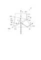
図1は、本実施形態に係るプロジェクター1の概略構成を示す模式図である。
本実施形態に係るプロジェクター1は、内部に設けられた光源装置31Aから出射された光束を変調して画像情報に応じた画像を形成し、当該画像をスクリーン等の被投射面上に拡大投射する表示装置である。このプロジェクター1は、図1に示すように、外装を構成する外装筐体2と、当該外装筐体2内に収納される光学ユニット3と、を備える。
この他、図示を省略するが、外装筐体2内には、プロジェクター1の構成部品を冷却する冷却装置、プロジェクター1の構成部材に電力を供給する電源装置、及び、プロジェクター1の動作を制御する制御装置等を備える。[First Embodiment]
Hereinafter, a first embodiment of the present invention will be described based on the drawings.
[Schematic configuration of projector]
FIG. 1 is a schematic diagram illustrating a schematic configuration of a projector 1 according to the present embodiment.
The projector 1 according to the present embodiment modulates the light beam emitted from the
In addition, although not shown, a cooling device that cools the components of the projector 1, a power supply device that supplies power to the components of the projector 1, and the operation of the projector 1 are controlled in the
[光学ユニットの構成]
光学ユニット3は、上記制御装置から入力される画像情報に応じた画像を形成及び投射する光学装置である。この光学ユニット3は、照明装置31、リレー装置32、ダイクロイックプリズム34、光変調装置35及び投射光学装置36を備える。[Configuration of optical unit]
The
[照明装置の構成]
照明装置31は、光源装置31A及び均一化装置31Bを備え、リレー装置32に、偏光方向が揃えられた均一な照明光を出射する。[Configuration of lighting device]
The
[光源装置の構成]
光源装置31Aは、少なくとも1つの固体光源を有する固体光源装置311と、集光光学装置312と、回転蛍光板313と、モーター314と、を有する。
固体光源装置311は、励起光として、青色のレーザー光(発光強度のピーク:略455nm)を出射するレーザー光源である。なお、固体光源装置311は、1つのレーザー光源(LD:Laser Diode)を有するものでもよく、複数のレーザー光源を有するものでもよい。また、発光強度のピークが455nm以外の波長の青色光を出射する光源装置を用いることもできる。
集光光学装置312は、第1レンズ3121及び第2レンズ3122を備える。集光光学装置312は、固体光源装置311から回転蛍光板313までの光路に配置され、上記励起光を略集光して、回転蛍光板313に入射させる。これら第1レンズ3121及び第2レンズ3122は、凸レンズである。[Configuration of light source device]
The
The solid-state
The condensing
回転蛍光板313は、モーター314によって回転される円板3131上に、入射される光の波長を変換する蛍光体層3132(蛍光体)が当該円板3131の周方向に沿って形成されたものである。この回転蛍光板313は、青色光が入射される側とは反対側に向けて赤色光及び緑色光を出射する。 The rotating
円板3131は、青色光を透過する材料からなる。円板3131の材料としては、例えば、石英ガラス、水晶、サファイア、光学ガラス及び透明樹脂等を採用できる。固体光源装置311から出射された青色光は、円板3131側から蛍光体層3132に入射される。この円板3131と蛍光体層3132との間には、青色光を透過し、緑色光及び赤色光を反射させるダイクロイック膜3133が設けられている。
蛍光体層3132は、上記励起光によって励起されて、緑色光及び赤色光を含む黄色光を出射する。本実施形態では、蛍光体層3132は、波長が略445nmの青色光によって励起される。この蛍光体層3132は、固体光源装置311からの励起光の一部を緑色光及び赤色光を含む光に変換し、かつ、残りの一部を変換せずに通過させる。この蛍光体層3132は、例えば、YAG系蛍光体である(Y,Gd)3(Al,Ga)5O12:Ceを含有する層である。The
The
このような光源装置31Aでは、固体光源装置311から出射された励起光(青色光)の一部の光が、蛍光体層3132を通過し、他の一部が、蛍光体層3132によって赤色光及び緑色光に波長変換される。なお、波長変換された赤色光及び緑色光は、蛍光体層3132にて散乱される。このことから、一部の光は、円板3131側に出射されるが、円板3131と蛍光体層3132との間に位置するダイクロイック膜3133によって、円板3131側(すなわち固体光源装置311側)に進行することが抑制される。これら赤色光及び緑色光は、上記一部の光である青色光とともに均一化装置31Bに入射される。なお、これら赤色光、緑色光及び青色光は、それぞれ、本発明の第1色光、第2色光及び第3色光に相当する。 In such a
[均一化装置の構成]
均一化装置31Bは、光源装置31Aから入射される光の中心軸に直交する面内の強度分布(照度分布)を均一化する。この均一化装置31Bは、コリメートレンズ315、第1レンズアレイ316、第2レンズアレイ317、偏光変換素子318及び重畳レンズ319を有する。
コリメートレンズ315は、凸レンズであり、光源装置31Aから入射される光を略平行化する。
第1レンズアレイ316は、図示を省略するが、コリメートレンズ315から入射される光を複数の部分光束に分割する複数の第1小レンズを有する。これら第1小レンズは、照明光軸Ax(設計上の光軸であり、光源装置31Aから出射された光の中心軸)に直交する面内にマトリクス状に配列されている。
第2レンズアレイ317は、図示を省略するが、上記複数の第1小レンズに対応する複数の第2小レンズを有する。この第2レンズアレイ317は、重畳レンズ319とともに、第1レンズアレイ316から入射される各第1小レンズの像を各光変調装置35R,35G,35Bの画像形成領域の近傍に結像させ、これにより、上記複数の部分光束は、各画像形成領域に重畳される。なお、各第2小レンズも照明光軸Axに直交する面内にマトリクス状に配列されている。[Configuration of homogenizer]
The
The
Although not shown, the
Although not shown, the
偏光変換素子318は、第1レンズアレイ316により分割された各部分光束の偏光方向を揃える機能を有する。
具体的に、偏光変換素子318は、回転蛍光板313からの光に含まれる偏光成分のうち一方の直線偏光成分(一方の偏光方向を有する直線偏光成分)をそのまま透過させるとともに、他方の直線偏光成分(他方の偏光方向を有する直線偏光成分)を照明光軸Axに垂直な方向に反射させる偏光分離層と、偏光分離層で反射された他方の直線偏光成分を照明光軸Axに平行な方向に反射させる反射層と、反射層で反射された他方の直線偏光成分を一方の直線偏光成分に変換する位相差板と、を有する。なお、本実施形態では、偏光変換素子318は、p偏光を出射する構成とされているが、s偏光を出射する構成としてもよい。The
Specifically, the
[リレー装置の構成]
リレー装置32は、照明装置31から出射された出射光をダイクロイックプリズム34に導く機能を有する。このリレー装置32は、全反射ミラー321、平行化レンズ322及び偏光分離装置323を備える。
全反射ミラー321は、照明装置31から入射される光を、平行化レンズ322に向けて反射させる。
平行化レンズ322は、全反射ミラー321から入射される光を略平行化する。[Configuration of relay device]
The
The
The
偏光分離装置323は、いわゆるプレート型の偏光ビームスプリッター(PBS:Polarization Beam Splitter)であり、p偏光及びs偏光のうち、一方の偏光光を通過させ、他方の偏光光を反射させる。
本実施形態では、偏光分離装置323は、p偏光を透過し、s偏光を反射させる。このため、全反射ミラー321及び平行化レンズ322を介して入射される光、すなわち、偏光変換素子318によってp偏光に揃えられた光は、偏光分離装置323を通過して、ダイクロイックプリズム34に出射される。一方、後述する光変調装置35によって変調され、ダイクロイックプリズム34を介して入射される変調光は、偏光分離装置323によって反射されて、投射光学装置36に入射される。The
In the present embodiment, the
[ダイクロイックプリズムの構成]
ダイクロイックプリズム34は、リレー装置32を介して入射される照明装置31の出射光(p偏光であり、青色光及び上記蛍光を含む光)から青、緑及び赤の3つの色光を分離して、対応する光変調装置35(35B,35G,35R)に入射させる機能を有する。また、このダイクロイックプリズム34は、これら光変調装置35により変調されて入射される各色光(s偏光)を合成した合成光を出射する機能を有する。
このようなダイクロイックプリズム34は、いわゆるギャップレスプリズムであり、第1プリズム341、第2プリズム342及び第3プリズム343と、第1プリズム341及び第2プリズム342の間に位置する第1色分離層344と、第2プリズム342及び第3プリズム343の間に位置する第2色分離層345と、を有し、これら各プリズム341〜343が組み合わされた構成を有する。[Configuration of dichroic prism]
The
The
第1プリズム341は、三角柱状に形成されており、各プリズム341〜343のうち、偏光分離装置323に最も近い位置に配置される。この第1プリズム341は、偏光分離装置323を通過した光が入射されるとともに、上記合成光が出射される入出射面3411を有する。この入出射面3411は、リレー装置32から入射される光の中心軸に対して直交するように配置される。
第1プリズム341は、第2プリズム342と接合されている。これら第1プリズム341及び第2プリズム342の間には、入出射面3411を介して入射された光のうち、赤色光を反射させ、緑色光及び青色光を透過させる上記第1色分離層344が配置されている。この第1色分離層344は、入出射面3411を介して第1プリズム341内に入射された光の中心軸に対して傾斜するように配置されている。The
The
この第1色分離層344にて反射された赤色光Rは、第1プリズム341の内側から入出射面3411に臨界角以上の角度で入射されて全反射され、第1プリズム341の出射面3412(第1出射面)から光変調装置35Rに向けて出射される。
一方、第1色分離層344を透過した青色光B及び緑色光Gは、第2プリズム342に入射される。The red light R reflected by the first
On the other hand, the blue light B and the green light G transmitted through the first
第2プリズム342は、断面が略台形の四角柱状に形成されており、上記第1プリズム341と第3プリズム343とに接合されている。これら第2プリズム342と第3プリズム343との間には、青色光Bを反射させ、緑色光Gを透過させる上記第2色分離層345が配置されている。 The
この第2色分離層345は、第1色分離層344を透過した青色光B及び緑色光Gの中心軸に対して傾斜するように配置されている。すなわち、第2色分離層345と第1色分離層344とは、入出射面3411に偏光分離装置323から入射される光の中心軸と略一致する照明光軸Axに対して、それぞれ異なる角度で傾斜している。これら第1色分離層344及び第2色分離層345の当該色光の中心軸に対する交差角は、第1色分離層344の方が、第2色分離層345より小さい。換言すると、第1色分離層344に対する光の入射角は、第2色分離層345に対する光の入射角より小さい。そして、第1色分離層344と第2色分離層345とは、当該中心軸に対する傾斜が逆となるように配置されている。なお、本実施形態では、第1色分離層344に対する光(青、緑及び赤の色光B,G,R)の入射角は+25度であるのに対し、第2色分離層345に対する光(青及び緑の色光B,G)の入射角は−40度である。 The second
このような第2色分離層345に第1色分離層344を介して入射される青色光B及び緑色光Gのうち、青色光Bは、当該第2色分離層345にて反射される。この青色光Bは、第2プリズム342内を進行して、当該第2プリズム342の出射面3421(第2出射面)から光変調装置35Bに向けて出射される。
一方、緑色光Gは、第2色分離層345を透過し、第3プリズム343に入射される。Of the blue light B and green light G incident on the second
On the other hand, the green light G passes through the second
第3プリズム343は、上記第2プリズム342と同様に断面が略台形の四角柱状に形成されており、上記のように、第2プリズム342と接合されている。この第3プリズム343に、上記第2色分離層345を介して入射された緑色光Gは、当該緑色光Gの進行方向に位置し、かつ、上記入出射面3411と略平行な出射面3431、すなわち、照明光軸Axに直交する出射面3431(第3出射面)から光変調装置35Gに向けて出射される。
そして、光変調装置35R,35G,35Bにて変調された各色光B,G,Rは、当該各光変調装置35R,35G,35Bへの各色光B,G,Rの入射経路を逆に辿って合成され、上記入出射面3411から合成光として偏光分離装置323に向けて出射される。Similar to the
Then, the color lights B, G, R modulated by the
[光変調装置の構成]
光変調装置35(青、緑及び赤の各色光用の光変調装置を、それぞれ35B,35G,35Rとする)は、それぞれ入射される青、緑及び赤の色光B,G,Rを変調して、画像情報に応じた色画像を形成するものである。詳述すると、各光変調装置35は、当該各色光B,G,Rを反射させる過程で変調する反射型光変調装置である。これら光変調装置35B,35G,35Rは、本実施形態では、反射型液晶ライトバルブにより構成されている。
各光変調装置35B,35G,35Rは、それぞれ、対応する出射面3421,3431,3412から入射される青、緑及び赤の色光B,G,Rの中心軸に直交するように、当該各出射面3421,3431,3412に対向配置される。そして、各光変調装置35B,35G,35Rは、入射される各色光を変調した変調光を、対応する出射面3421,3431,3412に入射させる。[Configuration of light modulation device]
The light modulation device 35 (light modulation devices for blue, green, and red color lights are respectively 35B, 35G, and 35R) modulate the incident blue, green, and red color lights B, G, and R, respectively. Thus, a color image corresponding to the image information is formed. More specifically, each
Each of the
[投射光学装置の構成]
投射光学装置36は、上記各光変調装置35により変調されて上記ダイクロイックプリズム34により合成された合成光(赤、緑及び青の変調光が合成された光)を、上記被投射面に向けて投射する。この投射光学装置36は、偏光分離装置323により反射された上記合成光が入射される位置に配置されている。このような投射光学装置36は、詳しい図示を省略するが、鏡筒と、当該鏡筒内にそれぞれ収納配置される複数のレンズとを有する組レンズとして構成されている。[Configuration of Projection Optical Device]
The projection
[第1色分離層及び第2色分離層による偏光種別と分離特性との関係]
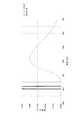
図2は、第1色分離層344が赤色光を分離し、第2色分離層345が青色光を分離する場合の偏光光の種別毎の各色分離層344,345の色分離特性を示す図である。なお、図2においては、第1色分離層344のp偏光及びs偏光の透過率を細かい点線(Tp)及び二点鎖線(Ts)によってそれぞれ示し、第2色分離層345のp偏光及びs偏光の透過率を実線(Tp)及び大きな点線(Ts)によってそれぞれ示している。以下の図においても同様である。
ここで、上記ダイクロイックプリズム34における第1色分離層344及び第2色分離層345の直線偏光の種別毎の色分離特性について説明する。
入射される光から所定閾値以上又は以下の光を反射させ、他の光を透過させる色分離層の色分離特性は、当該入射される光の入射角及び当該光の偏光方向によって変化する。[Relationship between polarization type and separation characteristics of the first color separation layer and the second color separation layer]
FIG. 2 is a diagram showing the color separation characteristics of the color separation layers 344 and 345 for each type of polarized light when the first
Here, the color separation characteristics for each type of linearly polarized light in the first
The color separation characteristics of the color separation layer that reflects light that is greater than or equal to a predetermined threshold from incident light and transmits other light varies depending on the incident angle of the incident light and the polarization direction of the light.
例えば、上記ダイクロイックプリズム34において、入射される光の入射角が略25度となる第1色分離層344が赤色光を分離する場合、透過と反射とが切り替わる波長の閾値は、図2に示すように、入射される光がp偏光である場合とs偏光である場合とで大きな差はない。具体的に、当該閾値は、入射光がp偏光である場合には略610nmであるのに対し、s偏光である場合には略605nmである。 For example, in the
これに対し、入射される光の入射角が略40度となる第2色分離層345が青色光を分離する場合、透過と反射とが切り替わる波長の閾値は、入射される光がp偏光であるかs偏光であるかによって大きく異なる。具体的に、当該閾値は、入射光がp偏光である場合には略480nmであるのに対し、s偏光である場合には略505nmである。
そして、第1色分離層344及び第2色分離層345に偏光分離装置323から入射される光はp偏光であり、各光変調装置35によって変調されて入射される変調光はs偏光である。On the other hand, when the second
The light incident on the first
このダイクロイックプリズム34を介して偏光分離装置323と光変調装置35とを光が往復する間に、入射光がs偏光である場合の上記閾値(略605nm)からp偏光である場合の上記閾値(略610nm)までの波長範囲の赤色光、及び、入射光がp偏光である場合の閾値(略480nm)からs偏光である場合の上記閾値(略505nm)までの波長範囲の青色光は、偏光分離装置323に戻らず、ロスされる。
このようなダイクロイックプリズム34が採用される場合で、偏光分離装置323から当該ダイクロイックプリズム34に入射される光に、特に上記波長範囲の青色光が多く含まれている場合には、投射画像における色バランスが適正ではなくなる可能性や、当該投射画像の輝度が低下する可能性がある。While the light travels back and forth between the
When such a
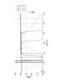
図3は、第1色分離層344が青色光を分離し、第2色分離層345が赤色光を分離する場合の偏光光の種別毎の各色分離層344,345の色分離特性を示す図である。なお、図3においては、第2色分離層345のp偏光及びs偏光の透過率を細かい点線(Tp)及び二点鎖線(Ts)によってそれぞれ示し、第1色分離層344のp偏光及びs偏光の透過率を実線(Tp)及び大きな点線(Ts)によってそれぞれ示している。
一方、入射される光の入射角が略25度となる第1色分離層344が青色光を分離する場合、図3に示すように、入射される光がp偏光である場合とs偏光である場合とで、上記閾値の差は小さくなる。具体的に、当該閾値は、入射光がp偏光である場合には略480nmであるのに対し、s偏光である場合には略495nmである。FIG. 3 is a diagram showing the color separation characteristics of the color separation layers 344 and 345 for each type of polarized light when the first
On the other hand, when the first
これに対し、入射される光の入射角が略40度となる第2色分離層345が赤色光を分離する場合、入射される光がp偏光である場合とs偏光である場合とで、上記閾値の差は大きくなる。具体的に、当該閾値は、入射光がp偏光である場合には略610nmであるのに対し、s偏光である場合には略565nmである。
そして、上記のように、各色分離層344,345に偏光分離装置323から入射される光はp偏光であり、各光変調装置35から入射される変調光はs偏光である。On the other hand, when the second
As described above, the light incident on the color separation layers 344 and 345 from the
このダイクロイックプリズム34を介して偏光分離装置323と光変調装置35とを光が往復する間に、入射光がs偏光である場合の上記閾値(略565nm)からp偏光である場合の上記閾値(略610nm)までの波長範囲の赤色光、及び、入射光がp偏光である場合の閾値(略480nm)からs偏光である場合の上記閾値(略495nm)までの波長範囲の青色光は、偏光分離装置323に戻らず、ロスされる。
このようなダイクロイックプリズム34が採用される場合で、偏光分離装置323から当該ダイクロイックプリズム34に入射される光に、特に上記波長範囲の赤色光が多く含まれている場合には、投射画像における色バランスが適正ではなくなる可能性や、当該投射画像の輝度が低下する可能性がある。While the light travels back and forth between the
When such a
[第1色分離層及び第2色分離層によって分離される色光の決定]
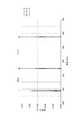
図4は、照明装置31から出射される出射光の波長分布を示す図である。
ここで、照明装置31から出射される光、すなわち、ダイクロイックプリズム34に入射される光は、上記のように、青色光Bと、緑色光G及び赤色光Rを含む蛍光Yとである。これらのうち、青色光Bは、図4に太い実線によって示すように、略455nmにピークを有し、当該蛍光Yは、図4において一点鎖線によって示すように、略475nmから700nm以上に亘る広い波長範囲の光である。このような蛍光Yに含まれる緑色光G及び赤色光Rでは、それぞれのピーク波長の間隔は、青色光B及び緑色光Gのピーク波長の間隔より小さい(狭い)ということができる。[Determination of Color Light Separated by First Color Separation Layer and Second Color Separation Layer]
FIG. 4 is a diagram illustrating the wavelength distribution of the emitted light emitted from the
Here, the light emitted from the
図5は、上記出射光の波長分布と、第1色分離層344が青色光を分離し、第2色分離層345が赤色光を分離するダイクロイックプリズム34を用いた場合の色分離特性とを示す図である。
上記図4にて示した波長分布の光を、上記図3に示した色分離特性を有するダイクロイックプリズム34にて分離及び合成する場合、図5に示すように、略455nmにピークを有する青色光Bは、第1色分離層344にてロスなく分離(反射)される。
しかしながら、広い波長範囲に亘る蛍光では、第2色分離層345にて光変調装置35Bにて変調された変調光(s偏光)が反射される際に、略565nmから略610nmまでの波長範囲の色光(緑色光及び赤色光の一部)が第2色分離層345を透過してしまうことから、当該波長範囲の色光は、上記入出射面3411に戻らず、偏光分離装置323に向けて出射されない。換言すると、投射画像に含まれる緑色光Gは、略490nmから略565nmまでの波長範囲の光に限定され、また、赤色光Rは、略610nm以上の波長範囲の光に限定される。
このように、光の入射角が小さい第1色分離層344にて青色光Bを分離(反射)させ、光の入射角が大きい第2色分離層345にて赤色光Rを分離(反射)させるダイクロイックプリズム34では、上記波長分布の光を出射する照明装置31が採用される場合に、光のロスが大きく、投射画像の輝度が低い他、当該投射画像の色バランスが適正でなくなるおそれがある。FIG. 5 shows the wavelength distribution of the emitted light and the color separation characteristics when the first
When the light having the wavelength distribution shown in FIG. 4 is separated and synthesized by the
However, in the fluorescence over a wide wavelength range, when the modulated light (s-polarized light) modulated by the
As described above, the blue light B is separated (reflected) by the first
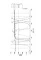
図6は、上記出射光の波長分布と、第1色分離層344が赤色光を分離し、第2色分離層345が青色光を分離するダイクロイックプリズム34を用いた場合の色分離特性とを示す図である。
これに対し、上記図4に示した波長分布の光を、上記図2に示した色分離特性を有するダイクロイックプリズム34にて分離及び合成する場合、図6に示すように、略455nmにピークを有する青色光Bは、第2色分離層345にてロスなく分離(反射)される。
一方、第1色分離層344にてロスが生じる上記波長範囲(略605nmから略610nmの波長範囲)は比較的狭いことから、当該第1色分離層344にて赤色光Rを分離することにより、上記図5にて示した場合(第2色分離層345が赤色光Rを分離する場合)に比べて、光のロスは少ない。
このように、照明装置31から出射される光の波長分布に応じて、光の入射角が小さい第1色分離層344と、光の入射角が大きい第2色分離層345とにより分離される色光(波長)を設定することにより、光のロスを低減でき、投射画像の輝度の低下を抑制できる他、当該投射画像の色バランスを維持できる。従って、本実施形態においては、上記波長分布の光を出射する照明装置31が採用される場合に、第1色分離層344により赤色光が分離(反射)され、第2色分離層345により青色光が分離(反射)されるダイクロイックプリズム34を採用することにより、当該効果を好適に奏することができる。FIG. 6 shows the wavelength distribution of the emitted light and the color separation characteristics when the first
On the other hand, when the light having the wavelength distribution shown in FIG. 4 is separated and synthesized by the
On the other hand, the wavelength range in which the loss occurs in the first color separation layer 344 (wavelength range from about 605 nm to about 610 nm) is relatively narrow. Therefore, by separating the red light R by the first
Thus, according to the wavelength distribution of the light emitted from the
[第1実施形態の効果]
以上説明した本実施形態に係るプロジェクター1によれば、以下の効果がある。
それぞれ光の入射角が異なる第1色分離層344及び第2色分離層345にて分離される色光は、第1色分離層344に対する光の入射角と、第2色分離層345に対する光の入射角と、光源装置31Aからの出射光の波長分布と、に基づいて設定される。これによれば、各色分離層344,345に対する光の入射角に基づいて、当該各色分離層344,345の偏光光毎の色分離特性を把握できる。そして、当該色分離特性と、出射光の波長分布とに基づいて、第1色分離層344及び第2色分離層345にて分離される色光を、光源装置31Aの出射光から各色光を分離し、変調された各色光を合成する際の光のロスが低減されるように設定できる。従って、光源装置31Aから出射されて画像として投射される光の利用効率を向上させることができ、投射画像の輝度が高めることができる。[Effect of the first embodiment]
The projector 1 according to the present embodiment described above has the following effects.
The color lights separated by the first
第1色分離層344は、赤色光Rを反射させ、青色光B及び緑色光Gを透過することにより、照明装置31から出射された光から、これら色光を分離する構成である。これによれば、照明装置31(光源装置31A)から出射されて入出射面3411を介して入射される光の中心軸(照明光軸Ax)に沿って、第1色分離層344及び第2色分離層345を直列に配置でき、これにより、第1プリズム341、第2プリズム342及び第3プリズム343を当該中心軸に沿って直列に配置できる。このため、例えば、第1色分離層344を透過した第1色光の進行方向側に第2プリズム342が配置され、当該第1色分離層344にて反射される第2色光及び第3色光の進行方向側に第2色分離層345及び第3プリズム343が配置されることによって、これら第2プリズム342及び第3プリズム343が互いに離れて配置される場合に比べて、ダイクロイックプリズム34をコンパクトに構成できる。従って、小型のダイクロイックプリズム34を採用でき、ひいては、プロジェクター1を小型化できる。 The first
ピーク波長の間隔が小さい緑色光G及び赤色光Rのうちの赤色光Rを、光の入射角が大きい第2色分離層345によって分離すると、上記のように、p偏光及びs偏光のうち、偏光変換素子318によって揃えられたp偏光がダイクロイックプリズム34に入射され、各光変調装置35によって変調された変調光であるs偏光が当該ダイクロイックプリズム34にて合成されて出射される際に、緑色光G及び赤色光Rのうちの少なくとも一方の色光がロスされる。このロスされた光は、投射光学装置36に入射されず、上記光の利用効率が低下する。
これに対し、光の入射角が小さい第1色分離層344(p偏光とs偏光とで色分離特性の差が小さい第1色分離層344)により、上記ピーク波長の間隔が小さい緑色光G及び赤色光Rのうちの赤色光Rを反射させて分離することにより、各色光B,G,Rの分離及び合成の際の光のロスを低減できる。従って、上記光の利用効率を確実に向上させることができ、投射画像の輝度を高めることができる。When the red light R of the green light G and the red light R having a small peak wavelength interval is separated by the second
On the other hand, the first
励起光である青色光Bが蛍光体層3132に入射されて出射される蛍光Yに含まれる緑色光G及び赤色光Rの波長幅は比較的広く、ピーク波長間の輝度も高い。このため、光の入射角が大きい第2色分離層345(p偏光とs偏光とで色分離特性の差が大きい第2色分離層345)によって、赤色光Rを分離(反射)させると、これら緑色光G及び赤色光Rの少なくとも一方の色光のロスが大きくなる。
これに対し、光の入射角が小さい第1色分離層344(p偏光とs偏光とで色分離特性の差が小さい第1色分離層344)によって、赤色光Rを反射させて分離することにより、緑色光G及び赤色光Rのロスを低減できる。従って、上記光の利用効率を確実に向上させることができ、投射画像の輝度を確実に高めることができる。The wavelength widths of the green light G and the red light R included in the fluorescence Y that is emitted when the blue light B, which is excitation light, enters the
On the other hand, the red light R is reflected and separated by the first
偏光変換素子318により偏光方向が揃えられた上記出射光をダイクロイックプリズム34、ひいては、各光変調装置35(35R,35G,35B)に入射させることができるので、光の利用効率を一層が高めることができる。
また、偏光変換素子318によって偏光方向が揃えられた上記出射光は、偏光分離装置323を透過してダイクロイックプリズム34に入射され、当該ダイクロイックプリズム34から出射される各光変調装置35の変調光は、当該偏光分離装置323によって投射光学装置36に向けて反射される。これによれば、偏光分離装置323とダイクロイックプリズム34との間で、光が往復するので、偏光分離装置323と、ダイクロイックプリズム34及び光変調装置35と、投射光学装置36との物理的な距離を短縮できる。従って、プロジェクター1を小型化できる。Since the emitted light whose polarization direction is aligned by the
The emitted light whose polarization direction is aligned by the
各光変調装置35は、反射型光変調装置であることから、各出射面3412,3421,3431から出射された光が、各光変調装置35によって変調されて、再度各出射面3412,3421,3431に入射されるまでの光路を短縮できる。従って、プロジェクター1をより小型化できる。 Since each
ダイクロイックプリズム34は、いわゆるギャップレスプリズムにより構成され、第1色分離層344にて反射された赤色光Rは、第1プリズム341の入出射面3411にて全反射されて、対応する光変調装置35Rに導かれる。また、第2色分離層345にて反射された青色光Bは、第2プリズム342内を通過して、対応する光変調装置35Bに導かれ、当該第2色分離層345を透過した緑色光Gは、第3プリズム343を透過して、対応する光変調装置35Gに導かれる。このようなダイクロイックプリズム34では、第1プリズム341と第1色分離層344との間、第1色分離層344と第2プリズム342との間、第2プリズム342と第2色分離層345との間、及び、第2色分離層と第3プリズム343との間に、隙間がない。このため、ダイクロイックプリズム34では、いわゆるフィリップスプリズムにより構成される場合に必要とされる制御することが難しい隙間を要しない。 The
[第2実施形態]
次に、本発明の第2実施形態について説明する。
本実施形態に係るプロジェクターは、上記プロジェクター1と同様の構成を有する、照明装置の構成と、上記第1色分離層344及び第2色分離層345により分離される色光とが異なる。これらの点で、本実施形態に係るプロジェクターと、上記プロジェクター1とは相違する。なお、以下の説明では、既に説明した部分と同一又は略同一である部分については、同一の符号を付して説明を省略する。[Second Embodiment]
Next, a second embodiment of the present invention will be described.
The projector according to the present embodiment has a configuration similar to that of the projector 1, and the configuration of the illumination device is different from the color light separated by the first
図7は、本実施形態に係るプロジェクターが有する照明装置31からの出射光の波長分布を示す図である。
本実施形態に係るプロジェクターは、照明装置31及びダイクロイックプリズム34の構成が異なる他は、上記プロジェクター1と同様の構成及び機能を有する。
これらのうち、照明装置31は、上記固体光源装置311から出射された励起光としての青色光を緑色光及び赤色光に波長変換する光源装置31Aを備える構成ではなく、赤、緑及び青の各色光を出射する3種のLD(Laser Diode)を有する光源装置を備える。
具体的に、これら3種のLDは、図7に示すように、略445nmにピークを有する青色光Bと、略525nmにピークを有する緑色光Gと、略638nmにピークを有する赤色光Rと、を出射する。そして、これら3つの色光B,G,Rは、均一化装置31Bを介して、リレー装置32に入射される。FIG. 7 is a diagram illustrating the wavelength distribution of the emitted light from the
The projector according to the present embodiment has the same configuration and function as the projector 1 except that the configurations of the
Among these, the
Specifically, as shown in FIG. 7, these three types of LDs include blue light B having a peak at about 445 nm, green light G having a peak at about 525 nm, and red light R having a peak at about 638 nm, , Is emitted. Then, these three colored lights B, G, R are incident on the
図7に示す波長分布の光を出射する光源装置を有する照明装置31が採用される場合、図2に示した色分離特性を有するダイクロイックプリズム34、及び、図3に示した色分離特性を有するダイクロイックプリズム34のいずれが採用される場合でも、各色光B,G,Rを分離可能である。しかしながら、LDは、温度によって出射される光の波長が変化することから、各色光のピーク波長が、第1色分離層344及び第2色分離層345の上記閾値から離れる方が好ましい。
従って、本実施形態における照明装置31が採用される場合には、青色光Bのピーク波長(略445nm)と緑色光Gのピーク波長(略525nm)との間の幅の方が、緑色光Gのピーク波長と赤色光Rのピーク波長(略638nm)との間の幅より狭いことから、図3に示した色分離特性を有するダイクロイックプリズム34が採用される。すなわち、この場合には、光の入射角が小さい第1色分離層344が青色光Bを反射させて分離し、光の入射角が大きい第2色分離層345が赤色光Rを反射させて分離するダイクロイックプリズム34が採用される。When the
Therefore, when the illuminating
図8は、本実施形態における照明装置31の出射光の波長分布と、当該照明装置31に応じて採用されるダイクロイックプリズム34の色分離特性とを示す図である。
これによれば、図8に示すように、図2に示した色分離特性を有するダイクロイックプリズム34が採用される場合に比べて、各色光B,G,Rのピーク波長を第1色分離層344及び第2色分離層345の閾値から離すことができる。従って、照明装置31から出射された光から3つの色光を分離し、各色光の変調光を合成する際に光のロスを低減でき、投射画像の輝度の低下を抑制できる。FIG. 8 is a diagram showing the wavelength distribution of the emitted light of the
According to this, as shown in FIG. 8, the peak wavelength of each color light B, G, R is set to the first color separation layer as compared with the case where the
[第2実施形態の効果]
以上説明した本実施形態に係るプロジェクターによれば、上記プロジェクター1と同様の効果を奏することができる他、以下の効果を奏することができる。
固体光源であるLDから出射される青色光、緑色光及び赤色光は、波長幅が比較的狭い光である。しかしながら、上記のように、LDから出射される各色光のピーク波長は、当該LDの点灯時の温度等によってずれる場合がある。
これに対し、本実施形態に係るプロジェクターでは、光の入射角が小さい第1色分離層344(p偏光とs偏光とで色分離特性の差が小さい第1色分離層344)によって、緑色光G及び赤色光Rよりピーク間隔が小さい青色光B及び緑色光Gのうち青色光Bを反射させて分離する。これによれば、上記各色光のピーク波長がずれた場合でも、これら青色光B及び緑色光Gのロスを低減できる。従って、上記光の利用効率を確実に向上させることができ、投射画像の輝度を確実に高めることができる。[Effects of Second Embodiment]
According to the projector according to the present embodiment described above, the same effects as the projector 1 can be obtained, and the following effects can be obtained.
Blue light, green light, and red light emitted from the LD, which is a solid light source, are light having a relatively narrow wavelength width. However, as described above, the peak wavelength of each color light emitted from the LD may be shifted depending on the temperature when the LD is turned on.
On the other hand, in the projector according to the present embodiment, the first color separation layer 344 (the first
[第3実施形態]
次に、本発明の第3実施形態について説明する。
本実施形態に係るプロジェクターは、上記プロジェクター1と同様の構成を有する。ここで、上記第2実施形態にて示したプロジェクターでは、出射光のピークの波長幅が比較的狭いLDを有する光源装置が採用された。これに対し、本実施形態に係るプロジェクターでは、出射光のピークの波長幅がやや広いLED(Light Emitting Diode)を有する光源装置が採用されている。この点で、本実施形態に係るプロジェクターと、上記プロジェクター1とは相違する。なお、以下の説明では、既に説明した部分と同一又は略同一である部分については、同一の符号を付して説明を省略する。[Third Embodiment]
Next, a third embodiment of the present invention will be described.
The projector according to this embodiment has the same configuration as the projector 1 described above. Here, in the projector shown in the second embodiment, a light source device having an LD having a relatively narrow wavelength range of the peak of emitted light is employed. On the other hand, in the projector according to the present embodiment, a light source device having an LED (Light Emitting Diode) having a slightly wider wavelength range of the peak of emitted light is employed. In this respect, the projector according to the present embodiment is different from the projector 1 described above. In the following description, parts that are the same as or substantially the same as those already described are assigned the same reference numerals and description thereof is omitted.
図9は、本実施形態に係るプロジェクターが有する照明装置31から出射される光の波長分布と、当該照明装置31に応じて採用されるダイクロイックプリズム34の色分離特性とを示す図である。
本実施形態に係るプロジェクターは、照明装置31及びダイクロイックプリズム34の構成が異なる他は、上記プロジェクター1と同様の構成及び機能を有する。
これらのうち、照明装置31は、上記第2実施形態における照明装置31と同様に、3色の固体光源を有する光源装置を備え、当該3色の固体光源は、赤、緑及び青の各色光をそれぞれ出射するLEDである。
これら3色のLEDは、図9に示すように、略460nmにピーク波長を有する青色光Bと、略525nmにピーク波長を有する緑色光Gと、略613nm及び略623nmにピーク波長を有する赤色光R(R1,R2)と、を出射する。そして、これら3つの色光B,G,Rは、均一化装置31Bを介して、リレー装置32に入射される。なお、これら赤、緑及び青の色光B,G,Rは、上記LDから出射される赤、緑及び青の色光B,G,Rに比べて波長幅が広い。FIG. 9 is a diagram illustrating the wavelength distribution of light emitted from the
The projector according to the present embodiment has the same configuration and function as the projector 1 except that the configurations of the
Among these, the illuminating
As shown in FIG. 9, these three colors of LED are blue light B having a peak wavelength at about 460 nm, green light G having a peak wavelength at about 525 nm, and red light having peak wavelengths at about 613 nm and about 623 nm. R (R1, R2) is emitted. Then, these three colored lights B, G, R are incident on the
上記3色のLEDを有する照明装置31が採用される場合、上記3色のLDを有する照明装置31が採用される場合と同様に、図2に示した色分離特性を有するダイクロイックプリズム34、及び、図3に示した色分離特性を有するダイクロイックプリズム34のいずれでも、各色光B,G,Rを分離可能である。しかしながら、各LEDから出射される色光B,G,Rの各波長幅は比較的広いことから、各色光B,G,Rのピーク波長が、上記第1色分離層344及び上記第2色分離層345の閾値から離れる方が好ましい。
従って、本実施形態における照明装置31が採用される場合でも、青色光Bのピーク波長(略460nm)と緑色光Gのピーク波長(略525nm)との間の幅の方が、緑色光Gのピークと赤色光R(R1,R2)のピーク波長(略613nm及び略623nm)との間の幅より狭いことから、図3に示した色分離特性を有するダイクロイックプリズム34が採用される。すなわち、この場合には、光の入射角が小さい第1色分離層344が青色光Bを反射させて分離し、光の入射角が大きい第2色分離層345が赤色光Rを反射させて分離するダイクロイックプリズム34が採用される。When the illuminating
Therefore, even when the
これによれば、図9に示すように、図2に示した色分離特性を有するダイクロイックプリズム34が採用される場合に比べて、各色光B,G,Rのピーク波長を第1色分離層344及び第2色分離層345の閾値から離すことができる。従って、上記と同様に、照明装置31から出射された光から3つの色光B,G,Rを分離し、各色光B,G,Rの変調光を合成する際に光のロスを低減でき、投射画像の輝度の低下を抑制できる。
以上説明した本実施形態に係るプロジェクターによれば、上記第2実施形態にて示したプロジェクターと同様の効果を奏することができる。
なお、上記3色のLEDのうち、赤色光Rを出射するLEDとして、ピーク波長が1つである赤色光を出射するLEDを採用してもよい。According to this, as shown in FIG. 9, the peak wavelength of each color light B, G, R is set to the first color separation layer as compared with the case where the
According to the projector according to the present embodiment described above, the same effect as that of the projector shown in the second embodiment can be obtained.
In addition, you may employ | adopt LED which radiate | emits red light with one peak wavelength as LED which radiate | emits red light R among said 3 color LED.
[実施形態の変形]
本発明は、上記各実施形態に限定されるものではなく、本発明の目的を達成できる範囲での変形、改良等は本発明に含まれるものである。
上記各実施形態では、色分離/合成装置としてのダイクロイックプリズム34は、いわゆるギャップレスプリズムであるとした。しかしながら、本発明はこれに限らない。例えば、ダイクロイックプリズム34は、他の形状のダイクロイックプリズムでもよく、いわゆるフィリップスプリズムであってもよい。[Modification of Embodiment]
The present invention is not limited to the above-described embodiments, and modifications, improvements, and the like within the scope that can achieve the object of the present invention are included in the present invention.
In each of the above embodiments, the
図10は、フィリップスプリズムにより構成されるダイクロイックプリズム37を示す模式図である。
フィリップスプリズムにより構成されるダイクロイックプリズム37は、ギャップレスプリズムにより構成されたダイクロイックプリズム34と同様に、図10に示すように、第1プリズム371、第2プリズム372及び第3プリズム373と、第1色分離層374及び第2色分離層375と、を有し、これらプリズム371〜373が組み合わされた構成を有する。FIG. 10 is a schematic diagram showing a
As shown in FIG. 10, the
第1プリズム371は、上記第1プリズム341と同様に、略三角柱状に形成され、第1〜第3プリズム371〜373のうち最も偏光分離装置323に近い位置に配置される。この第1プリズム371は、照明光軸Axに直交する入出射面3711を有し、当該入出射面3711を介して、偏光分離装置323を通過した光が第1プリズム371内に入射される。
このような第1プリズム371と、当該第1プリズム371に接合される第2プリズム372との間には、第1色分離層374が、照明光軸Axに対して傾斜するように配置されている。具体的に、第1色分離層374は、第1プリズム371において入出射面3711とは反対側の面に形成されている。Similar to the
A first
この第1色分離層374は、上記第1色分離層344と同様に、所定閾値以上又は以下の光を反射させ、その他の波長の光を透過させる。
例えば、第1色分離層374が、入射される光のうち、青色光Bを反射させ、緑色光G及び赤色光Rを透過させる構成である場合には、当該第1色分離層374によって反射された青色光Bは、第1プリズム371の内側から上記入出射面3711に臨界角以上の角度にて入射される。そして、当該青色光Bは、第1プリズム371の出射面3712(第1出射面)から、当該出射面3712に対向する青色光用の光変調装置35B(図示省略)に入射される。
一方、第1色分離層374に入射された緑色光G及び赤色光Rは、当該第1色分離層374を通過し、更に、第1プリズム371と第2プリズム372との間に形成された隙間GPを通過して、当該第2プリズム372に入射される。Similar to the first
For example, when the first
On the other hand, the green light G and the red light R incident on the first
第2プリズム372は、略三角柱状に形成されており、第1プリズム371との間に数μm程度の隙間GPを介して配置されている。この第2プリズム372と、第3プリズム373との間には、第2色分離層375が、照明光軸Axに対して上記第1色分離層374とは反対側に傾斜するように配置されている。
この第2色分離層375は、第2色分離層345と同様に、隙間GPを介して第1プリズム371から入射される光のうち、第1色分離層374とは異なる閾値以上又は以下の光を反射させ、その他の波長の光を透過させる。
例えば、第2色分離層375が、入射される緑色光G及び赤色光Rのうち、赤色光Rを反射させ、緑色光Gを透過させる構成である場合には、当該第2色分離層375によって反射された赤色光Rは、第2プリズム372の内側から第1プリズム371に対向する端面3721に臨界角以上の角度で入射される。そして、当該赤色光Rは、第2プリズム372の出射面3722(第2出射面)から、当該出射面3722に対向する赤色光用の光変調装置35R(図示省略)に入射される。
一方、第2色分離層375を透過した緑色光Gは、第2プリズム372と隙間なく接合される第3プリズム373に入射される。The
Similar to the second
For example, when the second
On the other hand, the green light G that has passed through the second
第3プリズム373は、断面が略台形の四角柱状に形成されている。この第3プリズム373は、第2プリズム372から光が入射される面とは反対側に、上記入出射面3711と平行な出射面3731、すなわち、照明光軸Axに直交する出射面3731を有する。そして、第3プリズム373に入射された緑色光Gは、出射面3731(第3出射面)から、当該出射面3731に対向する緑色光用の光変調装置35G(図示省略)に入射される。
そして、光変調装置35B,35G,35Rにて変調された各色光B,G,Rは、当該各光変調装置35B,35G,35Rへの各色光B,G,Rの入射経路を逆に辿って合成され、上記入出射面3711から合成光として偏光分離装置323に向けて出射される。The
Then, the color lights B, G, R modulated by the
このようなダイクロイックプリズム37においても、第1色分離層374及び第2色分離層375は、それぞれ異なる角度で照明光軸Axに対して交差しており、各色分離層374、375への光の入射角もそれぞれ異なる。
例えば、第1色分離層374は、照明光軸Axに沿って入射される光の入射角が−28度となるように傾斜しているのに対し、第2色分離層375は、当該照明光軸Axに沿って入射される光の入射角が+11度となるように傾斜している。
このため、フィリップスプリズムにより構成されたダイクロイックプリズム37が採用される場合でも、上記ギャップレスプリズムにより構成されたダイクロイックプリズム34が採用される場合と同様に、第1色分離層374及び第2色分離層375は、入射される直線偏光の種別毎に色分離特性がそれぞれ異なる。Also in such a
For example, the first
For this reason, even when the
このようなダイクロイックプリズム37が、上記ダイクロイックプリズム34に代えてプロジェクターに採用される場合でも、各色分離層374,375への光の入射角と、当該プロジェクターに用いられる照明装置31(詳しくは光源装置31A)による出射光の波長分布とに基づいて、第1色分離層374及び第2色分離層375にて分離される色光を設定することにより、上記プロジェクター1と同様の効果を奏することができる。 Even when such a
なお、フィリップスプリズムにより構成されたダイクロイックプリズム37では、上記数μm程度の隙間GPを隔てて配置する必要があるが、第2色分離層375にて反射された光を、第2プリズム372において第1プリズム371と対向する面にて内面反射させて、対応する光変調装置35に導く構成であるため、上記ギャップレスプリズムにより構成されたダイクロイックプリズム34において、色分離層に対する光の入射角の大きい第2色分離層345に対する光の入射角を小さくすることができる。このため、ダイクロイックプリズム37は、ダイクロイックプリズム34に比べて、直線偏光の種別毎の色分離特性が良い。
一方、ダイクロイックプリズム34では、上記のように、ダイクロイックプリズム37にて必要とされる隙間GPが不要であるため容易に製造できる。Incidentally, in the
On the other hand, the
また、ダイクロイックプリズム34の他の構成としては、図示を省略するが、照明装置31から出射された光が入射される入出射面を有する第1プリズムと、当該第1プリズムに対向配置される第2プリズムと、同じく第1プリズムに対向する第3プリズムと、を有し、第1プリズムと第2プリズムとの間に第1色分離層が位置し、第1プリズムと第3プリズムとの間に第2色分離層が位置するダイクロイックプリズムが挙げられる。 Further, as another configuration of the
このようなダイクロイックプリズムでは、例えば、第1プリズムの入出射面から入射された照明光(例えば、照明装置31からの出射光)のうち、第1色光は、当該照明光の中心軸に対して傾斜する第1色分離層を透過し、第2色光及び第3色光は当該第1色分離層にて反射されるように構成できる。この場合、第1色分離層を透過した第1色光は、第2プリズムに入射され、必要に応じて第2プリズム内で内面反射された後、当該第2プリズムの出射面(第2出射面)から対応する光変調装置に向けて出射させることができる。また、第1色分離層にて反射された第2色光及び第3色光は、必要に応じて第1プリズム内で内面反射された後(例えば入出射面にて内面反射された後)、当該第2色光及び第3色光の中心軸に対して傾斜する第2色分離層(第3プリズムにおいて第2色光及び第3色光の入射側に位置する第2色分離層)に入射させることができる。 In such a dichroic prism, for example, among the illumination light incident from the incident / exit surface of the first prism (for example, the exit light from the illumination device 31), the first color light is relative to the central axis of the illumination light. The first color separation layer that is inclined can be transmitted, and the second color light and the third color light can be reflected by the first color separation layer. In this case, the first color light transmitted through the first color separation layer is incident on the second prism, and is internally reflected in the second prism as necessary, and then the emission surface (second emission surface) of the second prism. ) To the corresponding light modulation device. In addition, the second color light and the third color light reflected by the first color separation layer are internally reflected in the first prism as necessary (for example, after being internally reflected on the incident / exit surface), It can be made to enter into the 2nd color separation layer (the 2nd color separation layer located in the entrance side of the 2nd color light and the 3rd color light in the 3rd prism) inclined with respect to the central axis of the 2nd color light and the 3rd color light .
第2色分離層に入射された第2色光及び第3色光のうち、一方の光は、第2色分離層にて反射され、更に必要に応じて第1プリズム内にて内面反射された後、当該第1プリズムの出射面(第1出射面)から対応する光変調装置に出射され、他方の光は、第2色分離層を透過して第3プリズムに入射され、必要に応じて第3プリズム内にて内面反射された後、当該第3プリズムの出射面(第3出射面)から対応する光変調装置に出射されるように構成できる。そして、各光変調装置にて反射される過程にて変調された各色光は、当該各光変調装置に入射される光路を逆に辿って合成されて、第1プリズムの入出射面から出射される。このようなダイクロイックプリズムを用いることにより、第1色分離層が第1色光を透過し、第2色光及び第3色光を反射させる構成をプロジェクターに採用できる。
そして、このようなダイクロイックプリズムが採用される場合には、それぞれ入射される光の中心軸に対して傾斜した各色分離層、すなわち、光の入射角がそれぞれ異なる各色分離層によって分離される色光は、第1色分離層に入射される各色光の入射角と、第2色分離層に入射される第2色光及び第3色光の入射角と、照明装置(光源装置)からの出射光の波長分布と、に基づいて設定される。これにより、上記と同様に、画像として投射される光の利用効率を向上させることができ、投射画像の輝度が高めることができる。One of the second color light and the third color light incident on the second color separation layer is reflected by the second color separation layer, and further, if necessary, after being internally reflected in the first prism. The light is emitted from the emission surface (first emission surface) of the first prism to the corresponding light modulation device, and the other light is transmitted through the second color separation layer and incident on the third prism. After being internally reflected in the three prisms, it can be configured to be emitted from the emission surface (third emission surface) of the third prism to the corresponding light modulation device. Then, each color light modulated in the process of being reflected by each light modulation device is synthesized by tracing back the optical path incident on each light modulation device and emitted from the incident / exit surface of the first prism. The By using such a dichroic prism, the projector can adopt a configuration in which the first color separation layer transmits the first color light and reflects the second color light and the third color light.
When such a dichroic prism is employed, each color separation layer inclined with respect to the central axis of the incident light, that is, the color light separated by each color separation layer having a different incident angle of light, The incident angle of each color light incident on the first color separation layer, the incident angle of the second color light and the third color light incident on the second color separation layer, and the wavelength of the emitted light from the illumination device (light source device) And distribution. Thereby, the utilization efficiency of the light projected as an image can be improved similarly to the above, and the brightness | luminance of a projection image can be raised.
上記各実施形態では、光変調装置35は、反射型光変調装置であった。しかしながら、本発明はこれに限らない。例えば、光変調装置35は、透過型ライトバルブ等の透過型光変調装置であってもよい。この場合、青、緑及び赤の各色光が出射されるダイクロイックプリズムの出射面に、各光変調装置による変調光を入射させる構成であればよい。また、反射型光変調装置が採用される場合でも、反射型液晶ライトバルブに限らず、液晶以外の光変調装置を用いてもよい。 In each of the above embodiments, the
上記各実施形態では、光学ユニット3は、図1において示した光学部品を有する構成であった。しかしながら、本発明はこれに限らない。例えば、光源装置は、LDやLED等の固体光源から青色光を出射する第1光源部と、当該第1光源部とは異なる固体光源から出射された励起光を蛍光体に入射させて、上記蛍光を出射する第2光源部と、これら第1光源部及び第2光源部から出射される光を合成して、均一化装置31Bに入射させる構成であってもよい。また、蛍光体層3132は、モーター314によって回転される円板3131に形成される構成に限らず、固定される基板上に形成されていてもよい。 In each of the above embodiments, the
上記各実施形態にて示した光源装置31Aが出射する青色光、緑色光及び赤色光の波長は一例であり、他の波長の青色光、緑色光及び赤色光を出射する光源装置を採用してもよい。また、ダイクロイックプリズム34,37における第1色分離層344,374及び第2色分離層345,375への光の入射角も、上記に限らず他の角度でもよい。
また、偏光変換素子318は、入射される光をp偏光に揃え、偏光分離装置323は、p偏光を透過し、s偏光を反射させる構成であった。しかしながら、本発明はこれに限らない。例えば、偏光変換素子318は、入射される光をs偏光に揃え、偏光分離装置323は、s偏光を透過し、p偏光を反射させる構成であってもよい。The wavelengths of the blue light, green light, and red light emitted from the
In addition, the
1…プロジェクター、31A…光源装置、311…固体光源装置(固体光源)、3132…蛍光体層(蛍光体)、318…偏光変換素子、323…偏光分離装置、34,37…ダイクロイックプリズム、341,371…第1プリズム、3411,3711…入出射面、3412,3712…出射面(第1出射面)、342,372…第2プリズム、3421,3722…出射面(第2出射面)、343,373…第3プリズム、3431,3731…出射面(第3出射面)、344,374…第1色分離層、345,375…第2色分離層、35(35R,35G,35B)…光変調装置、36…投射光学装置。 DESCRIPTION OF SYMBOLS 1 ... Projector, 31A ... Light source device, 311 ... Solid light source device (solid light source), 3132 ... Phosphor layer (phosphor), 318 ... Polarization conversion element, 323 ... Polarization separation device, 34, 37 ... Dichroic prism, 341 371: first prism, 3411, 3711: entrance / exit surface, 3412, 3712 ... exit surface (first exit surface), 342, 372 ... second prism, 3421, 3722 ... exit surface (second exit surface), 343 373 ... third prism, 3431, 3731 ... emission surface (third emission surface), 344, 374 ... first color separation layer, 345, 375 ... second color separation layer, 35 (35R, 35G, 35B) ... light modulation Device, 36... Projection optical device.
Claims (9)
Translated fromJapanese前記光源装置から出射された出射光に含まれる3つの色光のそれぞれに応じて設けられ、対応する色光をそれぞれ変調する3つの光変調装置と、
入出射面を介して内部に入射される前記出射光から前記3つの色光をそれぞれ分離して前記3つの光変調装置に入射させ、前記3つの光変調装置により変調されて入射される前記3つの色光を合成して前記入出射面を介して出射するダイクロイックプリズムと、
前記ダイクロイックプリズムにより合成された光を投射する投射光学装置と、を備え、
前記ダイクロイックプリズムは、
前記3つの光変調装置のうち、対応する光変調装置にそれぞれ対向する第1プリズム、第2プリズム及び第3プリズムと、
前記入出射面を有する第1プリズム、及び、前記第1プリズムに対向する前記第2プリズムの間に位置し、前記第1プリズム内に入射された前記出射光に含まれる前記3つの色光のうち、第1色光と、第2色光及び第3色光とを分離する第1色分離層と、
前記第3プリズムの光入射側に位置し、前記第1色分離層により分離された前記第2色光及び前記第3色光のうち、前記第2色光を反射させ、前記第3色光を透過させる第2色分離層と、を有し、
前記第1色分離層に対する前記3つの色光の入射角と、前記第2色分離層に対する前記第2色光及び前記第3色光の入射角とは、それぞれ異なり、
前記第1色分離層及び前記第2色分離層により分離される色光は、前記第1色分離層に入射される前記3つの色光の入射角と、前記第2色分離層に入射される前記第2色光及び前記第3色光の入射角と、前記出射光の波長分布と、に基づいて設定されることを特徴とするプロジェクター。A light source device;
Three light modulation devices that are provided according to each of the three color lights included in the emitted light emitted from the light source device and modulate the corresponding color lights,
The three color lights are separated from the outgoing light incident on the inside through the incident / exit surface and are incident on the three light modulators, modulated by the three light modulators and incident on the three light beams. A dichroic prism that synthesizes colored light and emits the light through the incident / exit surface;
A projection optical device for projecting light synthesized by the dichroic prism,
The dichroic prism is
Of the three light modulation devices, a first prism, a second prism, and a third prism respectively facing the corresponding light modulation device;
Of the three color lights included in the outgoing light that is located between the first prism having the incident / exit surface and the second prism facing the first prism and is incident on the first prism A first color separation layer that separates the first color light from the second color light and the third color light;
Of the second color light and the third color light, which are located on the light incident side of the third prism and separated by the first color separation layer, the second color light is reflected, and the third color light is transmitted. A two-color separation layer,
The incident angles of the three color lights with respect to the first color separation layer are different from the incident angles of the second color light and the third color light with respect to the second color separation layer, respectively.
The color lights separated by the first color separation layer and the second color separation layer are incident on the first color separation layer and incident angles of the three color lights and the second color separation layer. A projector set based on incident angles of the second color light and the third color light and a wavelength distribution of the emitted light.
前記第1色分離層は、前記第1色光を反射し、前記第2色光及び前記第3色光を透過させることを特徴とするプロジェクター。The projector according to claim 1.
The projector, wherein the first color separation layer reflects the first color light and transmits the second color light and the third color light.
前記第1色光、前記第2色光及び前記第3色光は、青色光、緑色光及び赤色光であり、
前記第1色分離層及び前記第2色分離層のうち、前記入射角が小さい色分離層は、青色光及び緑色光と、緑色光及び赤色光とのうち、ピーク波長の間隔が小さい2つの色光のうち一方を分離することを特徴とするプロジェクター。The projector according to claim 1 or 2,
The first color light, the second color light, and the third color light are blue light, green light, and red light,
Among the first color separation layer and the second color separation layer, the color separation layer having a small incident angle has two small peak wavelength intervals among blue light and green light, and green light and red light. A projector that separates one of colored lights.
前記光源装置は、
前記青色光を出射する固体光源と、
前記青色光が入射されて前記緑色光及び前記赤色光を含む蛍光を出射する蛍光体と、を備え、
前記ダイクロイックプリズムには、前記青色光及び前記蛍光が入射され、
前記第1色分離層及び前記第2色分離層のうち、前記入射角が小さい色分離層は、前記緑色光及び前記赤色光のうち、一方を反射させ、他方を透過させることを特徴とするプロジェクター。The projector according to claim 3.
The light source device
A solid-state light source that emits the blue light;
A phosphor that emits fluorescence including the green light and the red light when the blue light is incident thereon, and
The blue light and the fluorescence are incident on the dichroic prism,
Of the first color separation layer and the second color separation layer, the color separation layer having a small incident angle reflects one of the green light and the red light and transmits the other. projector.
前記光源装置は、前記青色光、前記緑色光及び前記赤色光をそれぞれ出射する固体光源を有し、
前記ダイクロイックプリズムには、前記固体光源から出射された前記青色光、前記緑色光及び前記赤色光が入射され、
前記第1色分離層及び前記第2色分離層のうち、前記入射角が小さい色分離層は、前記青色光及び前記緑色光のうち、一方を反射させ、他方を透過させることを特徴とするプロジェクター。The projector according to claim 3.
The light source device includes a solid light source that emits the blue light, the green light, and the red light, respectively.
The blue light, the green light and the red light emitted from the solid light source are incident on the dichroic prism,
Of the first color separation layer and the second color separation layer, the color separation layer having a small incident angle reflects one of the blue light and the green light and transmits the other. projector.
前記光源装置及び前記ダイクロイックプリズムの間に配置され、入射される光の偏光方向を揃える偏光変換素子と、
前記偏光変換素子及び前記ダイクロイックプリズムの間に配置され、前記偏光変換素子を介して入射される光を透過し、前記3つの光変調装置により変調されて前記ダイクロイックプリズムを介して入射される光を前記投射光学装置に向けて反射させる偏光分離装置と、を有することを特徴とするプロジェクター。The projector according to any one of claims 1 to 5,
A polarization conversion element arranged between the light source device and the dichroic prism and aligning the polarization direction of incident light;
Light that is disposed between the polarization conversion element and the dichroic prism, transmits light incident through the polarization conversion element, is modulated by the three light modulation devices, and is incident through the dichroic prism. And a polarization separation device that reflects the light toward the projection optical device.
前記ダイクロイックプリズムは、
前記第1色光が出射されるとともに、前記3つの光変調装置のうち前記第1色光を変調する光変調装置と対向する第1出射面と、
前記第2色光が出射されるとともに、前記3つの光変調装置のうち前記第2色光を変調する光変調装置と対向する第2出射面と、
前記第3色光が出射されるとともに、前記3つの光変調装置のうち前記第3色光を変調する光変調装置と対向する第3出射面と、を有し、
前記3つの光変調装置は、それぞれ、反射型光変調装置であることを特徴とするプロジェクター。The projector according to any one of claims 1 to 6,
The dichroic prism is
The first color light is emitted, and a first emission surface facing a light modulation device that modulates the first color light among the three light modulation devices;
The second color light is emitted, and a second emission surface facing a light modulation device that modulates the second color light among the three light modulation devices;
The third color light is emitted, and a third emission surface facing the light modulation device that modulates the third color light among the three light modulation devices,
Each of the three light modulation devices is a reflection type light modulation device.
前記第1色分離層と前記第2プリズムとの間には、隙間が設けられ、
前記第1プリズムと前記第1色分離層との間、前記第2プリズムと前記第2色分離層との間、及び、前記第2色分離層と前記第3プリズムとの間には、それぞれ隙間がなく、
前記第1色分離層への前記3つの色光の入射角は、前記第2色分離層への前記第2色光及び前記第3色光の入射角よりも大きいことを特徴するプロジェクター。The projector according to any one of claims 1 to 7,
A gap is provided between the first color separation layer and the second prism,
Between the first prism and the first color separation layer, between the second prism and the second color separation layer, and between the second color separation layer and the third prism, respectively. There is no gap
An incident angle of the three color lights to the first color separation layer is larger than an incidence angle of the second color light and the third color light to the second color separation layer.
前記第1プリズムと前記第1色分離層との間、前記第1色分離層と前記第2プリズムとの間、前記第2プリズムと前記第2色分離層との間、及び、前記第2色分離層と前記第3プリズムとの間には、それぞれ隙間がなく、
前記第1色分離層への前記3つの色光の入射角は、前記第2色分離層への前記第2色光及び前記第3色光の入射角よりも小さいことを特徴するプロジェクター。The projector according to any one of claims 1 to 7,
Between the first prism and the first color separation layer, between the first color separation layer and the second prism, between the second prism and the second color separation layer, and the second There are no gaps between the color separation layer and the third prism,
The projector according to claim 1, wherein incident angles of the three color lights to the first color separation layer are smaller than incident angles of the second color light and the third color light to the second color separation layer.
Priority Applications (2)
| Application Number | Priority Date | Filing Date | Title |
|---|---|---|---|
| JP2015050507AJP2016170301A (en) | 2015-03-13 | 2015-03-13 | Projector |
| PCT/JP2016/001077WO2016147578A1 (en) | 2015-03-13 | 2016-02-29 | Projector |
Applications Claiming Priority (1)
| Application Number | Priority Date | Filing Date | Title |
|---|---|---|---|
| JP2015050507AJP2016170301A (en) | 2015-03-13 | 2015-03-13 | Projector |
Publications (1)
| Publication Number | Publication Date |
|---|---|
| JP2016170301Atrue JP2016170301A (en) | 2016-09-23 |
Family
ID=56920283
Family Applications (1)
| Application Number | Title | Priority Date | Filing Date |
|---|---|---|---|
| JP2015050507APendingJP2016170301A (en) | 2015-03-13 | 2015-03-13 | Projector |
Country Status (2)
| Country | Link |
|---|---|
| JP (1) | JP2016170301A (en) |
| WO (1) | WO2016147578A1 (en) |
Cited By (1)
| Publication number | Priority date | Publication date | Assignee | Title |
|---|---|---|---|---|
| US11348981B2 (en) | 2019-09-30 | 2022-05-31 | Seiko Epson Corporation | Image light generation device and image display device |
Family Cites Families (8)
| Publication number | Priority date | Publication date | Assignee | Title |
|---|---|---|---|---|
| JPH10319344A (en)* | 1997-05-19 | 1998-12-04 | Matsushita Electric Ind Co Ltd | Projection display device |
| JP2002162613A (en)* | 2000-11-28 | 2002-06-07 | Seiko Epson Corp | projector |
| JP2005208256A (en)* | 2004-01-21 | 2005-08-04 | Fujinon Corp | Trimming filter, color separation optical system, color composite optical system, imaging apparatus and projector |
| WO2007015389A1 (en)* | 2005-08-04 | 2007-02-08 | Matsushita Electric Industrial Co., Ltd. | Illuminator and projection display employing it |
| US8305502B2 (en)* | 2009-11-11 | 2012-11-06 | Eastman Kodak Company | Phase-compensated thin-film beam combiner |
| JP5707968B2 (en)* | 2011-01-24 | 2015-04-30 | セイコーエプソン株式会社 | Lighting device and projector |
| JP6024289B2 (en)* | 2012-08-27 | 2016-11-16 | コニカミノルタ株式会社 | Projection display |
| JP6048002B2 (en)* | 2012-08-30 | 2016-12-21 | コニカミノルタ株式会社 | Color separation / combination prism |
- 2015
- 2015-03-13JPJP2015050507Apatent/JP2016170301A/enactivePending
- 2016
- 2016-02-29WOPCT/JP2016/001077patent/WO2016147578A1/ennot_activeCeased
Cited By (1)
| Publication number | Priority date | Publication date | Assignee | Title |
|---|---|---|---|---|
| US11348981B2 (en) | 2019-09-30 | 2022-05-31 | Seiko Epson Corporation | Image light generation device and image display device |
Also Published As
| Publication number | Publication date |
|---|---|
| WO2016147578A1 (en) | 2016-09-22 |
Similar Documents
| Publication | Publication Date | Title |
|---|---|---|
| US9918055B2 (en) | Polarization converting element, light source device, lighting device, and projector | |
| CN108572502B (en) | Projection type image display device | |
| CN111752081B (en) | Light source device, projector and light source module | |
| US8628199B2 (en) | Light source device with a plurality of light sources and a collimating lens | |
| US9323045B2 (en) | Illumination device and projector | |
| US8955985B2 (en) | Lighting device and projection-type display device using same | |
| US10162253B2 (en) | Illumination device and projector | |
| US20180149955A1 (en) | Illumination device and projector | |
| US10705416B2 (en) | Wavelength conversion element, light source apparatus, and projector | |
| CN112987470B (en) | Light source device and projector | |
| CN111290206A (en) | Projection type image display device | |
| CN114265275A (en) | Light source device and projector | |
| TWI461822B (en) | Illuminating unit and display | |
| KR20170133936A (en) | Light source device and projector comprising the same | |
| JP6743625B2 (en) | Wavelength conversion device, light source device, and projector | |
| KR102752334B1 (en) | Light source device and projection display device | |
| JP5423442B2 (en) | Lighting device and projector | |
| WO2016147580A1 (en) | Projector | |
| CN108388021A (en) | Polarization conversion device and projecting apparatus | |
| US10838290B2 (en) | Light source device and projector | |
| JP7188161B2 (en) | projector | |
| WO2016147578A1 (en) | Projector | |
| US9860497B2 (en) | Illumination device and projector | |
| WO2017208572A1 (en) | Image display device and light source device | |
| JP2018025711A (en) | Fluorescent light emitting element, light source device, and projector |