Movatterモバイル変換


[0]ホーム

URL:


JP2016169954A - Wireless communication terminal, wireless position specifying system, wireless position specifying method, and wireless position specifying program - Google Patents

Wireless communication terminal, wireless position specifying system, wireless position specifying method, and wireless position specifying program
Download PDF

Info

Publication number
JP2016169954A
JP2016169954AJP2015047960AJP2015047960AJP2016169954AJP 2016169954 AJP2016169954 AJP 2016169954AJP 2015047960 AJP2015047960 AJP 2015047960AJP 2015047960 AJP2015047960 AJP 2015047960AJP 2016169954 AJP2016169954 AJP 2016169954A
Authority
JP
Japan
Prior art keywords
beacon signal
area
wireless communication
communication terminal
information
Prior art date
Legal status (The legal status is an assumption and is not a legal conclusion. Google has not performed a legal analysis and makes no representation as to the accuracy of the status listed.)
Pending
Application number
JP2015047960A
Other languages
Japanese (ja)
Inventor
英三郎 村木
Eizaburo Muraki
英三郎 村木
Current Assignee (The listed assignees may be inaccurate. Google has not performed a legal analysis and makes no representation or warranty as to the accuracy of the list.)
NEC Corp
Original Assignee
NEC Corp
Priority date (The priority date is an assumption and is not a legal conclusion. Google has not performed a legal analysis and makes no representation as to the accuracy of the date listed.)
Filing date
Publication date
Application filed by NEC CorpfiledCriticalNEC Corp
Priority to JP2015047960ApriorityCriticalpatent/JP2016169954A/en
Publication of JP2016169954ApublicationCriticalpatent/JP2016169954A/en
Pendinglegal-statusCriticalCurrent

Links

Images

Landscapes

Abstract

Translated fromJapanese

【課題】複数のエリア内から自端末の位置を適切に特定することができる無線通信端末等を提供する。
【解決手段】無線通信端末1cは、複数のエリア内から自端末が存在する特定のエリアを検出可能な第1のビーコン信号と、特定のエリア内における自端末の位置を検出可能な第2のビーコン信号とを受信する。第1のビーコン信号を受信すると、第1のビーコン信号および第1のビーコン信号に関連するエリア情報に紐付けられた第2のビーコン信号を基に、特定のエリア内における自端末の位置を検出する、
【選択図】図16
A wireless communication terminal and the like capable of appropriately specifying the position of the terminal from a plurality of areas are provided.
A wireless communication terminal 1c includes a first beacon signal capable of detecting a specific area where the terminal is present from a plurality of areas, and a second beacon signal capable of detecting the position of the terminal within the specific area. A beacon signal is received. When the first beacon signal is received, the position of the own terminal in a specific area is detected based on the first beacon signal and the second beacon signal associated with the area information related to the first beacon signal. To
[Selection] Figure 16

Description

Translated fromJapanese

本発明は、無線通信を用いて端末の位置を特定する技術に関する。  The present invention relates to a technique for specifying the position of a terminal using wireless communication.

検索対象となるユーザの位置を、当該ユーザが保有する端末と通信することで特定する技術が開発されている。  A technique for identifying the position of a user to be searched by communicating with a terminal owned by the user has been developed.

特許文献1は、ビーコン信号を用いて、ゲート無線基地局と、車の運転手が有する移動無線電話端末との間で通信するETC(Electronic Toll Collection)システムを開示する。  Patent Document 1 discloses an ETC (Electronic Toll Collection) system that communicates between a gate radio base station and a mobile radio telephone terminal possessed by a car driver using a beacon signal.

特許文献2は、複数のエリアまたは階数から構成される屋内施設において、ユーザ端末が当該エリアに放送される音を収音することで、当該ユーザが現在位置するエリアを特定するシステムを開示する。  Patent Document 2 discloses a system for identifying an area where a user is currently located by collecting sound broadcast by the user terminal in an indoor facility composed of a plurality of areas or floors.

特許文献3は、屋内等のGPS(Global Positioning System)が使用困難な場所において、撮像画像の解析により受信装置を保有する人物の位置を検出し、当該検出位置のみにおいて位置送信装置をオン状態とすることで、省電力化を可能とする技術を開示する。  Patent Document 3 detects the position of a person holding a receiving device by analyzing a captured image in a place where GPS (Global Positioning System) is difficult to use, such as indoors, and sets the position transmitting device to an on state only at the detected position. Thus, a technique that enables power saving is disclosed.

特開2003-331329号公報JP2003-331329A特開2009-198209号公報JP 2009-198209特開2014-90389号公報JP 2014-90389 A

特許文献1の技術は、ゲート無線基地局が近距離に複数存在する場合に、ゲート無線基地局の各々が発信するビーコン信号が電波干渉をおこす。そのため、移動無線電話端末が適切なゲート無線基地局から発せられるビーコン信号を判断できないという問題がある。  In the technique ofPatent Literature 1, when a plurality of gate radio base stations exist at a short distance, beacon signals transmitted from each of the gate radio base stations cause radio wave interference. Therefore, there is a problem that the mobile radio telephone terminal cannot determine a beacon signal emitted from an appropriate gate radio base station.

特許文献2の技術は、複数のエリアが近接する場合に、放送される音が混在して、適切に位置が把握できないという問題がある。また、ユーザ端末がポケットやバッグの中にある場合、収音が困難となるという問題がある。  The technique ofPatent Document 2 has a problem that, when a plurality of areas are close to each other, sound to be broadcast is mixed and the position cannot be properly grasped. In addition, when the user terminal is in a pocket or bag, there is a problem that sound collection becomes difficult.

特許文献3の技術は、位置送信装置が近距離に複数存在する場合に、位置送信装置の各々が発信する、位置を特定する情報を含む無線信号が電波干渉をおこす。その結果、位置を検知したい人が備える受信装置が、位置送信装置から発せられる当該情報を適切に受信できないという問題がある。  In the technique ofPatent Document 3, when a plurality of position transmission devices exist at a short distance, a radio signal including information for specifying a position transmitted from each of the position transmission devices causes radio wave interference. As a result, there is a problem in that a receiving device included in a person who wants to detect a position cannot appropriately receive the information emitted from the position transmitting device.

本発明は、上記の問題点を解決するべくなされた。本発明は、無線通信を介して、人や物の位置を適切に特定可能とすることを主たる目的とする。  The present invention has been made to solve the above problems. The main object of the present invention is to make it possible to appropriately identify the position of a person or an object via wireless communication.

上記課題を解決するため、本発明の第1の観点は、
複数のエリア内から自端末が存在する特定のエリアを検出可能な第1のビーコン信号と、特定のエリア内における自端末の位置を検出可能な第2のビーコン信号とを受信する、無線通信端末である。
In order to solve the above problems, the first aspect of the present invention is to
A wireless communication terminal that receives a first beacon signal capable of detecting a specific area where the terminal is present from a plurality of areas and a second beacon signal capable of detecting the position of the terminal within the specific area It is.

本発明の第2の観点は、
上記に記載の無線通信端末を少なくとも1つと、
複数のエリア内から無線通信端末が存在する特定のエリアを検出可能な第1のビーコン信号を配信するゲート装置を少なくとも1つと、
特定のエリア内における無線通信端末の位置を検出可能な第2のビーコン信号を配信する無線信号送信機を少なくとも1つ
備える、無線位置特定システムである。
The second aspect of the present invention is:
At least one of the wireless communication terminals described above;
At least one gate device for delivering a first beacon signal capable of detecting a specific area where a wireless communication terminal exists from a plurality of areas;
A wireless location system is provided with at least one wireless signal transmitter that distributes a second beacon signal capable of detecting the position of a wireless communication terminal in a specific area.

本発明の第3の観点は、
複数のエリア内から自端末が存在する特定のエリアを検出可能な第1のビーコン信号を受信して特定のエリアを特定し、
特定のエリア内における自端末の位置を検出可能な第2のビーコン信号に基づいて自装置の位置を検出する、無線位置特定方法である。
The third aspect of the present invention is:
Receiving a first beacon signal capable of detecting a specific area where the terminal is present from a plurality of areas, specifying the specific area,
This is a wireless position specifying method for detecting the position of the own apparatus based on a second beacon signal capable of detecting the position of the own terminal in a specific area.

本発明の第4の観点は、
コンピュータを、
複数のエリア内から自端末が存在する特定のエリアを検出可能な第1のビーコン信号を受信して特定のエリアを特定する機能と、
特定のエリア内における自端末の位置を検出可能な第2のビーコン信号に基づいて自装置の位置を検出する機能、
として機能させるための無線位置特定プログラムである。
The fourth aspect of the present invention is:
Computer
A function for identifying a specific area by receiving a first beacon signal capable of detecting a specific area where the terminal is present from a plurality of areas;
A function of detecting the position of the own device based on a second beacon signal capable of detecting the position of the own terminal in a specific area;
It is a wireless position specifying program for functioning as.

本発明によれば、本発明は、無線通信を介して、人や物の位置を適切に特定することができる。  According to the present invention, the present invention can appropriately specify the position of a person or an object via wireless communication.

本発明の第一の実施形態に係る無線位置特定システム構成の一例を示す図である。It is a figure which shows an example of the radio | wireless position identification system structure which concerns on 1st embodiment of this invention.本発明の第一の実施形態に係る無線位置特定システムの一エリア構成の一例を示す図である。It is a figure which shows an example of the one area structure of the radio | wireless location system which concerns on 1st embodiment of this invention.本発明の第一の実施形態における無線通信端末の内部構成の一例を示す図である。It is a figure which shows an example of an internal structure of the radio | wireless communication terminal in 1st embodiment of this invention.本発明の第一の実施形態における位置情報記憶部の内部データ構成の一例を示す図である。It is a figure which shows an example of the internal data structure of the position information storage part in 1st embodiment of this invention.本発明の第一の実施形態における無線位置特定システム内の主に無線通信端末の動作を示すフローチャートである。It is a flowchart which mainly shows operation | movement of the radio | wireless communication terminal in the radio | wireless location system in 1st embodiment of this invention.本発明の第一の実施形態に係る無線位置特定システムにおける一エリア構成の一例を示す図である。It is a figure which shows an example of the one area structure in the radio | wireless location system which concerns on 1st embodiment of this invention.本発明の第一の実施形態に係る無線位置特定システムのゲート装置の変更例を示す構成図である。It is a block diagram which shows the example of a change of the gate apparatus of the radio | wireless location system which concerns on 1st embodiment of this invention.本発明の第二の実施形態に係る無線位置特定システム構成の一例を示す図である。It is a figure which shows an example of the radio | wireless location specification system structure which concerns on 2nd embodiment of this invention.本発明の第二の実施形態における無線通信端末の内部構成の一例を示す図である。It is a figure which shows an example of an internal structure of the radio | wireless communication terminal in 2nd embodiment of this invention.本発明の第二の実施形態における位置情報記憶部の内部データ構成の一例を示す図である。It is a figure which shows an example of the internal data structure of the position information storage part in 2nd embodiment of this invention.本発明の第二の実施形態における無線位置特定システム内の主に無線通信端末の動作を示すフローチャートである。It is a flowchart which mainly shows operation | movement of the radio | wireless communication terminal in the radio | wireless location system in 2nd embodiment of this invention.本発明の第三の実施形態に係る無線位置特定システム構成の一例を示す図である。It is a figure which shows an example of the radio | wireless location system structure which concerns on 3rd embodiment of this invention.本発明の第三の実施形態における無線通信端末の内部構成の一例を示す図である。It is a figure which shows an example of the internal structure of the radio | wireless communication terminal in 3rd embodiment of this invention.本発明の第三の実施形態における位置情報サーバの内部構成の一例を示す図である。It is a figure which shows an example of the internal structure of the position information server in 3rd embodiment of this invention.本発明の第三の実施形態における無線位置特定システムの動作を示すフローチャートである。It is a flowchart which shows operation | movement of the radio | wireless location system in 3rd embodiment of this invention.本発明の第四の実施形態に係る無線通信端末の構成の一例を示す図である。It is a figure which shows an example of a structure of the radio | wireless communication terminal which concerns on 4th embodiment of this invention.

次に図面を参照して、本発明の実施形態を説明する。以下の図面の記載において、同一または類似の部分には同一または類似の符号を付している。ただし、図面は本発明の実施形態における構成を模式的に表している。更に以下に記載される本発明の実施形態は一例であり、その本質を同一とする範囲において適宜変更可能である。
<第一の実施形態>
(無線位置特定システム)
本発明の第一の実施形態に係る無線位置特定システム100の構成について説明する。図1に示すように、本実施形態に係る無線位置特定システム100は、ゲート装置10a、10b、10c、10d、10eと、無線信号送信機20A、20B、20C、20Dと、無線通信端末1と、ビーコン管理サーバ2と、を備える。無線通信端末1は、携帯電話、スマートフォン、タブレット端末、ノートパソコン等の無線通信端末である。図1において、無線通信端末1は1台のみであるが、無線通信端末1は、無線位置特定システム100内に複数存在して構わない。
Next, an embodiment of the present invention will be described with reference to the drawings. In the following description of the drawings, the same or similar parts are denoted by the same or similar reference numerals. However, the drawings schematically show the configuration of the embodiment of the present invention. Furthermore, the embodiment of the present invention described below is an example, and can be appropriately changed within a range in which the essence is the same.
<First embodiment>
(Wireless location system)
A configuration of thewireless location system 100 according to the first embodiment of the present invention will be described. As shown in FIG. 1, thewireless location system 100 according to the present embodiment includesgate devices 10a, 10b, 10c, 10d, and 10e,wireless signal transmitters 20A, 20B, 20C, and 20D, and awireless communication terminal 1. Thebeacon management server 2 is provided. Thewireless communication terminal 1 is a wireless communication terminal such as a mobile phone, a smartphone, a tablet terminal, or a laptop computer. In FIG. 1, there is only onewireless communication terminal 1, but a plurality ofwireless communication terminals 1 may exist in thewireless location system 100.

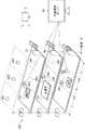
無線位置特定システム100は、ビル等の屋内において、人や物の位置を的確に特定することで、当該人や物に対して、位置情報を提供する。本実施形態においては、人(ユーザ)に対して位置情報を提供することを仮定して、以下の説明を行う。図1に示すように、屋内はエリア毎(図1においてはエリアA-1、A-2、B-1、B-2)に区分されている。ユーザは無線通信端末1を携帯した状態で、各エリアを移動する。各エリアの矢印は、ユーザの進路方向を示す。ゲート装置10a〜10eは、各エリアの入り口に設置される。ユーザは、あるエリアから別エリアに移動する際には、当該ゲート装置10a〜10eを必ず通過する。無線信号送信機20A〜20Dは、各エリアに設置される、無線通信端末1に無線信号を送信する機器である。図1においては、エリアA-1内には、無線信号送信機20Dが設置される。エリアA-2内には、無線信号送信機20Aが設置される。エリアB-1内には、無線信号送信機20Cが設置される。エリアB-2内には、無線信号送信機20Bが設置される。  The wirelessposition specifying system 100 provides position information to the person or the object by accurately specifying the position of the person or the object indoors such as a building. In the present embodiment, the following description is given on the assumption that position information is provided to a person (user). As shown in FIG. 1, indoors are divided into areas (areas A-1, A-2, B-1, and B-2 in FIG. 1). The user moves in each area while carrying thewireless communication terminal 1. The arrow of each area shows a user's course direction. Thegate devices 10a to 10e are installed at the entrance of each area. When the user moves from one area to another area, the user always passes through thegate devices 10a to 10e. The radio signal transmitters 20A to 20D are devices that transmit radio signals to theradio communication terminal 1 installed in each area. In FIG. 1, a radio signal transmitter 20D is installed in area A-1. A radio signal transmitter 20A is installed in the area A-2. A radio signal transmitter 20C is installed in the area B-1. Aradio signal transmitter 20B is installed in the area B-2.

本実施形態においては、ゲート装置10a〜10eおよび無線信号送信機20A〜20Dが、ユーザが保有する無線通信端末1の位置を特定する無線信号として、ビーコン信号を使用する。また、本願においては、ビーコン信号を使用するシステムとして、例えば、iBeacon(登録商標、以下同様)システムの構成を採用する。ビーコン管理サーバ2はiBeaconシステムにおいて使用されるビーコン信号を管理するサーバである。尚、本願の実施形態においてはiBeaconシステムを採用することを前提に説明するが、本願の実施形態は当該システムに限られない。例えば、RFID(radio frequency identifier)技術等を用いても本発明の実施形態に係る無線位置特定システムを実装することは可能である。  In the present embodiment, thegate devices 10a to 10e and the radio signal transmitters 20A to 20D use a beacon signal as a radio signal that specifies the position of theradio communication terminal 1 owned by the user. In the present application, for example, a configuration of an iBeacon (registered trademark, hereinafter the same) system is adopted as a system that uses a beacon signal. Thebeacon management server 2 is a server that manages beacon signals used in the iBeacon system. In the embodiment of the present application, description will be made on the assumption that the iBeacon system is adopted, but the embodiment of the present application is not limited to the system. For example, it is possible to implement the radio location system according to the embodiment of the present invention even using RFID (radio frequency identifier) technology or the like.

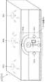
本実施形態における「エリア」についての理解を助けるために、図2を用いて、図1のエリアA-2内における、ゲート装置10aおよび無線信号送信機20Aについて詳細に説明する。  In order to help understanding of “area” in the present embodiment, thegate device 10a and the radio signal transmitter 20A in the area A-2 of FIG. 1 will be described in detail with reference to FIG.

図2に示すように、ゲート装置10aは、エリアA-2の入り口に設置された門を備える。ゲート装置10aは、当該門におけるユーザが通過する側の表面または略表面には、無線信号送信機20Ga、20Gb、20Gcを備える。これらは、ユーザが備える無線通信端末1と無線通信可能となるように門に固定、接着、圧着または嵌め込みされている。尚、図2において門はアーチ状となっているが、本実施形態に係る門の形状はこれに限られず、四角形状等でも良い。  As shown in FIG. 2, thegate device 10a includes a gate installed at the entrance of the area A-2. Thegate device 10a includes radio signal transmitters 20Ga, 20Gb, and 20Gc on the surface or substantially the surface of the gate through which the user passes. These are fixed, adhered, crimped, or fitted to the gate so that wireless communication with thewireless communication terminal 1 provided by the user is possible. In addition, although the gate is arched in FIG. 2, the shape of the gate which concerns on this embodiment is not restricted to this, A square shape etc. may be sufficient.

無線信号送信機20Aは、ビーコン信号の送信性能を高めるためにエリア内に複数設置されることが望ましい。図2において、無線信号送信機20Aは、3つの無線信号送信機20Aa、20Ab、20Acから構成され、無線信号送信機20Aa〜20Acは、エリア内の天井に設置されている。尚、設置位置は天井に限られず、エリア内の無線通信可能ないずれの位置(例えば、壁側面等)に配置されていても構わない。  It is desirable that a plurality of wireless signal transmitters 20A are installed in the area in order to improve the transmission performance of beacon signals. In FIG. 2, the radio signal transmitter 20A includes three radio signal transmitters 20Aa, 20Ab, and 20Ac, and the radio signal transmitters 20Aa to 20Ac are installed on the ceiling in the area. The installation position is not limited to the ceiling, and may be arranged at any position (for example, a wall side surface) in the area where wireless communication is possible.

本願においては、上述したようにiBeaconシステムを使用するので、ゲート装置10aが備える無線信号送信機20Ga〜20Gcと、無線信号送信機20Aa〜20Acとは、基本的に同じ構成を備えるペリフェラル装置である。  In the present application, since the iBeacon system is used as described above, the radio signal transmitters 20Ga to 20Gc and the radio signal transmitters 20Aa to 20Ac included in thegate device 10a are basically peripheral devices having the same configuration. .

ここでiBeaconシステムについて簡単に説明する。ビーコン管理サーバ2は、無線信号送信機20Ga〜20Gcおよび無線信号送信機20Aa〜20Acが発信するビーコン情報を管理する。このビーコン情報には少なくともuuid, major value, minor valueの情報が含まれる。「uuid」は、ビーコン信号そのものや、所属するエリアを識別するために使用される一意の値である。「major value」は16ビットの符号無し整数値で、uuidが同じビーコン信号を区別するために使用する。「minor value」は、16ビットの符号無し整数値で、uuidおよびmajor valueが同じビーコン信号を区別するために使用する。本実施形態においては、無線位置特定システム100内のゲート装置10a〜10eおよび無線信号送信機20A〜20D(無線信号送信機20A〜20Dがそれぞれ複数の無線送信機から構成される場合、それらの無線送信機も含む。本実施形態において以下同様。)の各々が、一意に識別可能となるように、上記のuuid, major value, minor valueの情報を用いて、ビーコン管理サーバ2は、無線信号送信機を特定するのに必要なビーコン情報の設定を予め行っているものとする。当該設定を実装するにあたり、上述したビーコン情報を用いた多様な設定手法が考えられるが、設定手法は、ビーコン管理サーバ2の管理者または無線位置測定システム100の管理者(設計者)が、自由に決定できるものとする。  Here, the iBeacon system will be briefly described. Thebeacon management server 2 manages beacon information transmitted from the radio signal transmitters 20Ga to 20Gc and the radio signal transmitters 20Aa to 20Ac. This beacon information includes at least uuid, major value, and minor value information. “Uuid” is a unique value used to identify the beacon signal itself and the area to which it belongs. “Major value” is a 16-bit unsigned integer value, and is used to distinguish beacon signals having the same uuid. “Minor value” is a 16-bit unsigned integer value, and is used to distinguish beacon signals having the same uuid and major value. In the present embodiment, thegate devices 10a to 10e and the radio signal transmitters 20A to 20D (when the radio signal transmitters 20A to 20D are each composed of a plurality of radio transmitters) in theradio location system 100 Thebeacon management server 2 uses the above uuid, major value, and minor value information to transmit a radio signal so that each of them can be uniquely identified. It is assumed that the setting of beacon information necessary for specifying the machine is performed in advance. In implementing the setting, various setting methods using the above-described beacon information can be considered. However, the setting method can be freely set by the administrator of thebeacon management server 2 or the administrator (designer) of the wirelessposition measurement system 100. Can be determined.

図2において、エリアA-2内の無線信号送信機20Ga〜20Gcおよび無線信号送信機20Aa〜20Acは、それぞれに割り当てられたuuid, major value, minor valueのビーコン情報を含むビーコン信号を配信する。  In FIG. 2, the radio signal transmitters 20Ga to 20Gc and the radio signal transmitters 20Aa to 20Ac in the area A-2 distribute beacon signals including beacon information of uuid, major value, and minor value assigned thereto.

iBeaconシステムにおいて、ビーコン信号の電波強度は、強から弱に向かって、「Immediate」、「Near」、「Far」の3種類に判別できる。尚、「Immediate」は、ビーコン信号を配信元から半径10cm(センチメートル)の距離以内で受信したことを、「Near」はビーコン信号を配信元から半径1m(メートル)の距離以内で受信したこと、「Far」はビーコン信号を配信元から半径10mの距離以内で受信したことを表す。よって、本実施形態においては、ゲート装置10a〜10eにおける、人等が通過する通路部分の形状を、無線通信端末1が、「Immediate」または「Near」の強度でビーコン信号を受信可能に設計する。例えば、ゲート装置10a〜10eの幅および高さの少なくとも片方を一般的な人間が一人程度通行できる程度の幅または高さとなるように設計する(図2参照)。この際、無線通信端末1は、ユーザの衣服やバッグ等の中に存在していても、ビーコン信号を受信することができる。尚、無線通信端末1は、ゲート装置10a〜10eから受信する信号強度よりも弱い「Far」の信号強度で、無線信号送信機20A〜20Dからのビーコン信号を受信するものとする。
(無線通信端末)
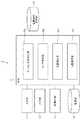
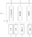
本実施形態に係る無線通信端末1は、図3に示すように、入力部11、出力部12、通信インタフェース(I/F)部13、記憶部14、CPU(Central Processing Unit)15、および、位置情報記憶部16を備える。CPU15は、ビーコン信号受信部15a、エリア特定部15b、位置検出部15cおよび位置提示部15dを備える。
In the iBeacon system, the radio wave intensity of a beacon signal can be discriminated into three types, “Immediate”, “Near”, and “Far”, from strong to weak. “Immediate” received the beacon signal within a radius of 10 cm (centimeter) from the distribution source, and “Near” received the beacon signal within a radius of 1 m (meter) from the distribution source. “Far” indicates that the beacon signal is received within a radius of 10 m from the distribution source. Therefore, in this embodiment, the shape of the passage portion through which a person or the like passes in thegate devices 10a to 10e is designed so that thewireless communication terminal 1 can receive a beacon signal with an intensity of “Immediate” or “Near”. . For example, at least one of the widths and heights of thegate devices 10a to 10e is designed to have a width or height that allows a general person to pass by about one person (see FIG. 2). At this time, thewireless communication terminal 1 can receive a beacon signal even if thewireless communication terminal 1 is present in a user's clothes or bag. Thewireless communication terminal 1 receives beacon signals from the wireless signal transmitters 20A to 20D with a signal strength of “Far” that is weaker than the signal strength received from thegate devices 10a to 10e.
(Wireless communication terminal)
As illustrated in FIG. 3, thewireless communication terminal 1 according to the present embodiment includes aninput unit 11, anoutput unit 12, a communication interface (I / F)unit 13, astorage unit 14, a CPU (Central Processing Unit) 15, and A positioninformation storage unit 16 is provided. TheCPU 15 includes a beaconsignal receiving unit 15a, anarea specifying unit 15b, aposition detecting unit 15c, and aposition presenting unit 15d.

位置情報記憶部16は、位置に関する情報(以下、位置情報と記載)を格納する。位置情報は、一例として、図4に示すようなデータ構成となっており、「エリア情報」、「送信ID(IDentifier)情報」、「信号強度情報」、「地図情報」および「干渉エリア情報」を一つのレコードとして記憶する。  The positioninformation storage unit 16 stores information related to the position (hereinafter referred to as position information). The position information has a data structure as shown in FIG. 4 as an example, and “area information”, “transmission ID (IDentifier) information”, “signal strength information”, “map information”, and “interference area information”. Is stored as one record.

エリア情報は、図1に示す無線位置特定システム100内の各エリアを特定するための情報であり、エリア情報はビーコン信号(第1のビーコン信号)を一意に特定可能に紐付けられている。  The area information is information for specifying each area in the wirelessposition specifying system 100 shown in FIG. 1, and the area information is associated with the beacon signal (first beacon signal) so as to be uniquely specified.

送信ID情報は、各エリアに存在する無線信号送信機20A〜20Dを識別するための識別子であり、第1のビーコン信号に関連するエリア情報に紐付けられた第2のビーコン信号である。例えば、図2に示すエリアA−2における無線信号送信機20A(即ち、無線信号送信機20Aa〜20Ac)は、図4の表の上から二番目(矢印箇所の列)に示されている。この情報によると、無線信号送信機20Aaは、第2のビーコン信号と対応する、送信ID「A−2−1」を、無線信号送信機20Abは、送信ID「A−2−2」を、無線信号送信機20Acは、送信ID「A−2−3」を各々備える。  The transmission ID information is an identifier for identifying the radio signal transmitters 20A to 20D existing in each area, and is a second beacon signal associated with the area information related to the first beacon signal. For example, the radio signal transmitter 20A (that is, the radio signal transmitters 20Aa to 20Ac) in the area A-2 shown in FIG. 2 is shown second from the top of the table in FIG. According to this information, the wireless signal transmitter 20Aa transmits the transmission ID “A-2-1” corresponding to the second beacon signal, and the wireless signal transmitter 20Ab transmits the transmission ID “A-2-2”. Each of the radio signal transmitters 20Ac includes a transmission ID “A-2-3”.

信号強度情報は、無線通信端末1が受信するビーコン信号の強度の測定結果を示す情報である。  The signal strength information is information indicating a measurement result of the strength of the beacon signal received by thewireless communication terminal 1.

地図情報は、各エリア内の全ての信号強度情報から分析された、各エリア内における無線通信端末1の現在の位置を示す地図の情報である。例えば、エリア内の地図上に、ユーザ(無線通信端末1)の現在位置を、認知しやすいように赤色等に印付けした画像情報である。尚、ユーザが認知できる方法は画像表示に限られない。例えば、所定箇所を通過する際にユーザに音、振動(バイブレーション)、無線通信端末1が備えるランプ(不図示)の点滅、点灯等により認知させてもよい。  The map information is map information indicating the current position of thewireless communication terminal 1 in each area, analyzed from all signal strength information in each area. For example, image information in which the current position of the user (wireless communication terminal 1) is marked in red or the like so as to be easily recognized on a map in the area. The method that the user can recognize is not limited to image display. For example, when passing a predetermined location, the user may be made aware by sound, vibration (vibration), blinking or lighting of a lamp (not shown) provided in thewireless communication terminal 1.

干渉エリア情報は、現在ユーザ(無線通信端末1)が位置するエリアの周辺エリアであり、且つ、物理的に電波干渉が発生するエリアを示す情報である。  The interference area information is information indicating an area around the area where the user (wireless communication terminal 1) is currently located and an area where radio wave interference physically occurs.

ビーコン信号受信部15aは、ゲート装置10a〜10eから配信されるビーコン信号(第1のビーコン信号)および無線信号送信機20A〜20Dから配信されるビーコン信号(第2のビーコン信号)を受信する。  The beaconsignal receiving unit 15a receives a beacon signal (first beacon signal) distributed from thegate devices 10a to 10e and a beacon signal (second beacon signal) distributed from the radio signal transmitters 20A to 20D.

エリア特定部15bは、受信したビーコン信号の強度を基に、無線通信端末1の存在するエリアを特定する。例えば、エリア特定部15bは、ビーコン信号の強度を計測する。その強度が所定以上の場合、例えば、「Immediate」、または、「Immediate」若しくは「Near」の強度でビーコン信号を受信した場合に、エリア特定部15bは、ユーザが無線通信端末1を保有した状態でゲート装置10a〜10eのいずれかを通過した、即ち、エリアが変更した(またはエリアに初めて入った)と判断する。この場合、エリア特定部15bは、ビーコン信号に含まれるビーコン情報からエリア情報(図4参照)を取得し、後述する記憶部14内に、一時記憶させる。尚、ビーコン信号の強度は、ビーコン信号受信部15aによって計測されてもよい。  Thearea specifying unit 15b specifies an area where thewireless communication terminal 1 exists based on the intensity of the received beacon signal. For example, thearea specifying unit 15b measures the strength of the beacon signal. When the intensity is greater than or equal to a predetermined value, for example, when a beacon signal is received with an intensity of “Immediate”, or “Immediate” or “Near”, thearea specifying unit 15b is in a state where the user has thewireless communication terminal 1 It is determined that any one of thegate devices 10a to 10e has passed, that is, the area has changed (or has entered the area for the first time). In this case, thearea specifying unit 15b acquires area information (see FIG. 4) from the beacon information included in the beacon signal, and temporarily stores it in thestorage unit 14 described later. Note that the strength of the beacon signal may be measured by the beaconsignal receiving unit 15a.

位置検出部15cは、無線信号送信機20A〜20Dから受信したビーコン信号の強度情報(主に強度「Far」)を基に、あるエリア内における、無線通信端末1の存在する位置を検出する。ビーコン信号強度情報は信号強度情報として、位置情報記憶部16(図4参照)に格納される。  Theposition detection unit 15c detects the position where thewireless communication terminal 1 exists in a certain area based on the strength information (mainly strength “Far”) of the beacon signal received from the wireless signal transmitters 20A to 20D. The beacon signal strength information is stored in the position information storage unit 16 (see FIG. 4) as signal strength information.

位置提示部15dは、信号強度情報を基に、エリア内における現在の無線通信端末1の位置を検出し、検出した位置を地図等の画像(地図情報)内に反映させた状態で、無線通信端末1の出力部12に表示等する。検出された地図情報は、位置情報記憶部16(図4参照)に格納される。尚、地図情報の提示は、ユーザに現在位置を知らせるため、ユーザを所定の場所に誘導するため等に用いられる。  Theposition presentation unit 15d detects the current position of thewireless communication terminal 1 in the area based on the signal strength information, and wireless communication is performed in a state where the detected position is reflected in an image (map information) such as a map. Displayed on theoutput unit 12 of theterminal 1. The detected map information is stored in the position information storage unit 16 (see FIG. 4). The presentation of the map information is used for notifying the user of the current position, for guiding the user to a predetermined location, and the like.

入力部11は、キーボード、マウス、タッチパネル(ソフトウェアキーボードを含む)等を指す。出力部12は、モニタ、プリンタ、スピーカ等を指す。通信インタフェース部13は、無線通信端末1と外部装置との有線または無線による通信を行うためのインタフェースである。尚、入力部11は、通信インタフェース部13を介して、データを入力しても構わない。記憶部14は、プログラム等を格納するROM(Read Only Memory)、作業データ等を格納するRAM(Random Access Memory)、その他のデータ記憶可能なメモリ装置を指す。  Theinput unit 11 refers to a keyboard, a mouse, a touch panel (including a software keyboard), and the like. Theoutput unit 12 indicates a monitor, a printer, a speaker, or the like. Thecommunication interface unit 13 is an interface for performing wired or wireless communication between thewireless communication terminal 1 and an external device. Theinput unit 11 may input data via thecommunication interface unit 13. Thestorage unit 14 indicates a ROM (Read Only Memory) that stores programs and the like, a RAM (Random Access Memory) that stores work data and the like, and other memory devices capable of storing data.

図3に示す無線通信端末1内のビーコン信号受信部15a、エリア特定部15b、位置検出部15cおよび位置提示部15dは、機能ブロック単位で表されたプログラムと捉えることができる。そしてこれらのプログラムは、CPU15または記憶部14内のROMおよびRAM等に格納されている。CPU15がこれらのプログラムを適宜演算処理することでこれらの機能は実行される。尚、上述した各部は、電子回路等の専用のハードウェアで構成されていてもよい。
(無線位置特定システムの動作)
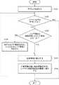
以下、無線位置特定システム100に係る動作を、主に無線通信端末1の動作を中心として、図5を参照して説明する。
The beaconsignal receiving unit 15a, thearea specifying unit 15b, theposition detecting unit 15c, and theposition presenting unit 15d in thewireless communication terminal 1 illustrated in FIG. 3 can be regarded as programs expressed in units of functional blocks. These programs are stored in theCPU 15 or the ROM and RAM in thestorage unit 14. These functions are executed by theCPU 15 appropriately calculating these programs. Each unit described above may be configured by dedicated hardware such as an electronic circuit.
(Operation of wireless positioning system)
Hereinafter, the operation according to thewireless location system 100 will be described with reference to FIG. 5 mainly focusing on the operation of thewireless communication terminal 1.

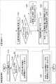
ステップS101において、無線通信端末1の入力部11等を介したユーザ操作により、無線位置特定システムに係るアプリケーションが起動する。尚、常時自動的に起動可能に初期設定しておいても構わない。  In step S101, an application related to the wireless location system is activated by a user operation via theinput unit 11 of thewireless communication terminal 1 or the like. It should be noted that it may be initially set so that it can always be automatically activated.

ステップS102において、ビーコン信号受信部15aは、ゲート装置10a〜10eおよび無線信号送信機20A〜20Dから配信されるビーコン信号を受信したか否かを判断する。ビーコン信号を受信したと判断した場合、処理はステップS103に進められる。  In step S102, the beaconsignal receiving unit 15a determines whether or not a beacon signal distributed from thegate devices 10a to 10e and the radio signal transmitters 20A to 20D has been received. If it is determined that a beacon signal has been received, the process proceeds to step S103.

ステップS103において、エリア特定部15bは、受信したビーコン信号の強度が「Immediate」または「Near」である場合、当該ビーコン信号に含まれるビーコン情報の内、エリア情報(図4参照)を取得する。さらに、エリア特定部15bは、取得したエリア情報が、記憶部14内に一時記憶されるエリア情報と同一かを判断する。これは、受信したビーコン信号の強度が「Immediate」または「Near」である場合、ゲート装置10a〜10e(図1参照)の内のいずれかを通過したと考えられるためである。尚、記憶部14内のエリア情報のデフォルト値は「0」等と設定する。  In step S103, when the intensity of the received beacon signal is “Immediate” or “Near”, thearea specifying unit 15b acquires area information (see FIG. 4) in the beacon information included in the beacon signal. Furthermore, thearea specifying unit 15 b determines whether the acquired area information is the same as the area information temporarily stored in thestorage unit 14. This is because when the intensity of the received beacon signal is “Immediate” or “Near”, it is considered that one of thegate devices 10a to 10e (see FIG. 1) has passed. Note that the default value of the area information in thestorage unit 14 is set to “0” or the like.

エリア特定部15bが同一のエリア情報では無い判断した場合、処理はステップS104へ進められ、エリア特定部15bが同一のエリア情報であると判断した場合、処理はステップS105へ進められる。  If thearea specifying unit 15b determines that the area information is not the same, the process proceeds to step S104. If thearea specifying unit 15b determines that the area information is the same, the process proceeds to step S105.

ステップS104において、エリア特定部15bは、ビーコン信号に含まれるビーコン情報からエリア情報(図4参照)を取得し、記憶部14内に、一時記憶させる。これにより、ユーザが現在のエリアから別のエリアに移動するまでの間、エリア特定部15bは、ビーコン信号受信部15aに対し、現在のエリア以外のエリアからの無線信号送信機20A〜20Dが配信するビーコン信号(即ち、干渉するエリア情報に含まれるエリアからのビーコン信号)を、受信不可能となるよう設定する。例えば、エリアA−2のエリア情報を基準以上の強度で取得すると、ビーコン信号受信部15aは、無線信号送信機の送信IDがA−2で始まる信号、即ち、送信IDがA−2−1、A−2−2、A−2−3(図4参照)のみのビーコン信号を受信する。  In step S <b> 104, thearea specifying unit 15 b acquires area information (see FIG. 4) from the beacon information included in the beacon signal and temporarily stores it in thestorage unit 14. Thereby, until the user moves from the current area to another area, thearea specifying unit 15b distributes the radio signal transmitters 20A to 20D from areas other than the current area to the beaconsignal receiving unit 15a. The beacon signal to be received (that is, the beacon signal from the area included in the interfering area information) is set so as not to be received. For example, when the area information of the area A-2 is acquired with an intensity higher than the reference, the beaconsignal receiving unit 15a has a signal whose transmission ID of the wireless signal transmitter starts with A-2, that is, the transmission ID is A-2-1. , A-2-2, A-2-3 (see FIG. 4) only beacon signals are received.

ステップS105において、位置検出部15cは、受信したビーコン信号の強度情報を基に、あるエリア内における、無線通信端末1の存在する位置を検出する。位置検出の処理について説明する。図6は、図2に示すエリアA−2の上面図である。無線通信端末1の現在の位置から近い順に、無線信号送信機20Ab、無線信号送信機20Aa、無線信号送信機20Acが存在する。この場合、ビーコン信号の受信強度(RSSI:Received Signal Strength Indicator)は、一例として、無線信号送信機20Abは受信強度「強」(-30dBm(ディービーエム:1mWを0デシベルとして、電力の大きさをデシベルで表したもの)程度)、無線信号送信機20Aaは受信強度「中」(-60dBm程度)、無線信号送信機20Acは受信強度「弱」(-90dBm程度)の様に計測されるとする。位置検出部15cは、計測されたこれらのビーコン信号の強度を信号強度情報として、位置情報記憶部16(図4参照)に格納する。  In step S105, theposition detection unit 15c detects the position where thewireless communication terminal 1 exists in a certain area based on the received intensity information of the beacon signal. The position detection process will be described. 6 is a top view of area A-2 shown in FIG. A radio signal transmitter 20Ab, a radio signal transmitter 20Aa, and a radio signal transmitter 20Ac exist in order from the current position of theradio communication terminal 1. In this case, as an example, the received signal strength indicator (RSSI) of the beacon signal is set such that the radio signal transmitter 20Ab has a received strength of “strong” (−30 dBm (DBM: 1 mW is 0 decibels). It is assumed that the radio signal transmitter 20Aa is measured so that the reception intensity is “medium” (about −60 dBm), and the radio signal transmitter 20Ac is measured so that the reception intensity is “weak” (about −90 dBm). . Theposition detection unit 15c stores the measured intensity of these beacon signals as signal intensity information in the position information storage unit 16 (see FIG. 4).

ステップS106において、位置提示部15dは、位置情報記憶部16から検出された信号強度情報(主に強度「Far」)を取得し、当該信号強度を基に、エリア内における現在の無線通信端末1の位置を計算することによって検出する。尚、ユーザ(無線通信端末1)が存在するエリアを特定しやすい様に、エリアを更に細かい区画に設定し、どの区画にユーザが存在するかを当該区画のIDで示すようにしてもよい。例えば、図2のエリアA−2の床面を、縦列および横行の二次元表で表現する。この場合、一例として縦行をa、b、cと、横列をα、β、γとし、ユーザのエリアA−2内の現在位置を9区画(3行×3列)の内のいずれかの区画であると表す。当該区画のIDは、9種類(aα、aβ、aγ、bα、bβ、bγ、cα、cβ、cγ)となる。  In step S106, theposition presentation unit 15d acquires the signal strength information (mainly strength “Far”) detected from the locationinformation storage unit 16, and based on the signal strength, the currentwireless communication terminal 1 in the area. Detect by calculating the position of. In addition, in order to easily identify the area where the user (wireless communication terminal 1) exists, the area may be set to a smaller section, and which section the user exists may be indicated by the ID of the section. For example, the floor surface of area A-2 in FIG. 2 is represented by a two-dimensional table of columns and rows. In this case, as an example, the vertical rows are a, b, c, the horizontal rows are α, β, γ, and the current position in the user's area A-2 is any one of 9 sections (3 rows × 3 columns). Represents a compartment. There are nine types of IDs (aα, aβ, aγ, bα, bβ, bγ, cα, cβ, cγ).

更に、位置提示部15dは、検出した位置をエリア地図等の画像(地図情報)内に反映させた状態で、無線通信端末1の出力部12に表示等する。位置提示部15dは、表示する地図情報を、位置情報記憶部16(図4参照)に格納する。ユーザは、無線通信端末1の出力部12に表示された地図情報を見ることで、現在位置を知る。更にユーザは、地図情報に表示された目的地までの誘導ルート(線等)を目視することで、目的地までのルートを知ることが出来る。  Further, theposition presentation unit 15d displays the detected position on theoutput unit 12 of thewireless communication terminal 1 in a state where the detected position is reflected in an image (map information) such as an area map. Theposition presentation unit 15d stores the map information to be displayed in the position information storage unit 16 (see FIG. 4). The user knows the current position by viewing the map information displayed on theoutput unit 12 of thewireless communication terminal 1. Further, the user can know the route to the destination by visually observing the guidance route (line or the like) to the destination displayed in the map information.

この後、処理はステップS102へ戻され、ビーコン信号受信部15aがビーコン信号を受信しなくなると、無線位置特定システム100の管理するエリア内から、ユーザが無線通信端末1と共に出たと判断し、本処理を終了する。  Thereafter, the process returns to step S102, and when the beaconsignal receiving unit 15a does not receive the beacon signal, it is determined that the user has come out with thewireless communication terminal 1 from the area managed by thewireless location system 100, End the process.

以上説明したように、本発明の第一の実施形態によると、ビーコン信号の通信を介して、無線通信端末1の位置を適切に特定可能とすることができる。この理由は、無線通信端末1がゲート装置10a〜10eを通過する度に、エリア特定部15bは、ユーザが現在位置するエリア情報を判断し、現在位置するエリア情報におけるビーコン情報のみを取得し現在位置を判断するからである。これにより、他のエリア情報からのビーコン信号の干渉を遮断できるので、精度のよい位置検出を行うことができる。更に、本発明の第一の実施形態によると、ビーコン信号を利用するため、ユーザがゲート装置10a〜10eを通過する度に無線通信端末1を鞄や服等から取り出す必要が無い。
(変更例)
図7は、本発明の第一の実施形態の変更例を示す図である。本発明の第一の実施形態の変更例では、ゲート装置10およびゲート装置10´を備え、図7に示すようにゲート装置10、10´を近距離で並べて設置する。この設置により、ゲート装置10の無線信号送信機から取得するエリア情報と、ゲート装置10´の無線信号送信機から取得するエリア情報とを比較でき、無線通信端末1が、あるエリアから別のエリアに移動する際に、当該無線通信端末1の移動する方向を検知することができる。これにより、より素早くユーザの進行方向が判別できる。
<第二の実施形態>
(無線位置特定システム)
本発明の第二の実施形態に係る無線位置特定システム200の構成について説明する。図8に示すように、本実施形態に係る無線位置特定システム200は、ゲート装置10f、10g、10hと、無線信号送信機20E、20F、20H、20I、20J、20K、20L、20M、20Nと、無線通信端末1aと、ビーコン管理サーバ2と、を備える。
As described above, according to the first embodiment of the present invention, it is possible to appropriately identify the position of thewireless communication terminal 1 through communication of a beacon signal. The reason for this is that each time thewireless communication terminal 1 passes through thegate devices 10a to 10e, thearea specifying unit 15b determines the area information in which the user is currently located, acquires only beacon information in the currently located area information, This is because the position is judged. Thereby, since interference of beacon signals from other area information can be blocked, accurate position detection can be performed. Furthermore, according to 1st embodiment of this invention, since a beacon signal is utilized, it is not necessary to take out the radio |wireless communication terminal 1 from a bag, clothes, etc. whenever a user passesgate apparatus 10a-10e.
(Example of change)
FIG. 7 is a diagram showing a modification of the first embodiment of the present invention. In a modification of the first embodiment of the present invention, agate device 10 and a gate device 10 'are provided, and thegate devices 10, 10' are arranged side by side at a short distance as shown in FIG. By this installation, the area information acquired from the radio signal transmitter of thegate device 10 and the area information acquired from the radio signal transmitter of thegate device 10 ′ can be compared, and theradio communication terminal 1 can be compared from one area to another area. When moving, the direction in which thewireless communication terminal 1 moves can be detected. Thereby, a user's advancing direction can be discriminate | determined more quickly.
<Second Embodiment>
(Wireless location system)
The configuration of thewireless location system 200 according to the second embodiment of the present invention will be described. As shown in FIG. 8, theradio location system 200 according to the present embodiment includes agate device 10f, 10g, 10h, andradio signal transmitters 20E, 20F, 20H, 20I, 20J, 20K, 20L, 20M, 20N. The wireless communication terminal 1a and thebeacon management server 2 are provided.

無線位置特定システム200において、屋内における複数のエリアは水平方向(床面)および垂直方向(フロア階数)で表され、第1のビーコン信号は、垂直方向における無線通信端末1aの位置を特定可能であり、第2のビーコン信号は、水平方向における無線通信端末1aの位置を特定可能である。  In the wirelessposition identification system 200, a plurality of indoor areas are represented in the horizontal direction (floor surface) and the vertical direction (floor floor number), and the first beacon signal can identify the position of the wireless communication terminal 1a in the vertical direction. Yes, the second beacon signal can specify the position of the wireless communication terminal 1a in the horizontal direction.

無線位置特定システム200は、図8に示すように、ビル等の屋内における各階層の入り口にゲート装置10f〜10hを設置する。更に、各階層においては、エリア毎に所定間隔を空けて、無線信号送信機20E〜20Nが設置される。本実施例においては、図8に示すように、1階にエリア1−A、1−B、1−Cが設定され、各エリアには、当該順序に従い、無線信号送信機20E、20F、20Hが配置される。2階にエリア2−A、2−B、2−Cが設定され、各エリアには、当該順序に従い、無線信号送信機20I、20J、20Kが配置される。3階にエリア3−A、3−B、3−Cが設定され、各エリアには、当該順序に従い、無線信号送信機20L、20M、20Nが配置される。  As shown in FIG. 8, thewireless location system 200 installs gate devices 10 f to 10 h at the entrance of each floor indoors such as a building. Further, in each hierarchy,radio signal transmitters 20E to 20N are installed with a predetermined interval for each area. In this embodiment, as shown in FIG. 8, areas 1-A, 1-B, and 1-C are set on the first floor, and theradio signal transmitters 20E, 20F, and 20H are set in each area according to the order. Is placed. Areas 2-A, 2-B, and 2-C are set on the second floor, andradio signal transmitters 20I, 20J, and 20K are arranged in each area according to the order. Areas 3-A, 3-B, and 3-C are set on the third floor, andradio signal transmitters 20L, 20M, and 20N are arranged in each area according to the order.

ユーザは、ある階から別の階に移動する際には、当該ゲート装置10g〜10hを必ず通過する。その他においては、第一の実施形態と同様であるため説明を省略する。
(無線通信端末)
本実施形態に係る無線通信端末1aは、図9に示すように、入力部11、出力部12、通信インタフェース部13、記憶部14、CPU25、および、位置情報記憶部26を備える。CPU25は、ビーコン信号受信部15a、エリア特定部15b、サブエリア特定部15e、位置検出部15cおよび位置提示部15dを備える。
When the user moves from one floor to another, he always passes through thegate devices 10g to 10h. Since others are the same as those of the first embodiment, description thereof is omitted.
(Wireless communication terminal)
As illustrated in FIG. 9, the wireless communication terminal 1 a according to the present embodiment includes aninput unit 11, anoutput unit 12, acommunication interface unit 13, astorage unit 14, aCPU 25, and a positioninformation storage unit 26. TheCPU 25 includes a beaconsignal receiving unit 15a, anarea specifying unit 15b, a subarea specifying unit 15e, aposition detecting unit 15c, and aposition presenting unit 15d.

位置情報記憶部26は、位置情報を格納する。本実施形態における位置情報は、一例として、図10に示すようなデータ構成となっており、「エリア情報」、「送信ID情報」、「信号強度情報」、「地図情報」および「干渉エリア情報」を一つのレコードとして記憶する。  The positioninformation storage unit 26 stores position information. The position information in the present embodiment has a data configuration as shown in FIG. 10 as an example, and “area information”, “transmission ID information”, “signal strength information”, “map information”, and “interference area information”. "As one record.

サブエリア特定部15eは、現在ユーザ(無線通信端末1a)が位置するエリアの周辺エリアであり、且つ、物理的に電波干渉が発生するエリア(以下、干渉エリアと記載)を特定する。本実施形態においては、当該干渉エリアから受信するビーコン信号を、無線通信端末1aの位置を特定するための補助情報として利用する。  Thesub-area specifying unit 15e specifies an area around the area where the user (wireless communication terminal 1a) is currently located and an area where radio wave interference is physically generated (hereinafter referred to as an interference area). In the present embodiment, a beacon signal received from the interference area is used as auxiliary information for specifying the position of the wireless communication terminal 1a.

位置検出部15cは、エリア特定部45bおよびサブエリア特定部45cが指定したエリア(図10参照)から受信するビーコン信号を基に、無線通信端末1aの現在位置を検出する。  Theposition detection unit 15c detects the current position of the wireless communication terminal 1a based on the beacon signal received from the area (see FIG. 10) designated by thearea specifying unit 45b and thesub-area specifying unit 45c.

その他においては、第一の実施形態と同様であるため説明を省略する。
(無線位置特定システムの動作)
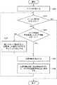
以下、無線位置特定システム200に係る動作を、主に無線通信端末1aの動作を中心として、図11を参照して説明する。
Since others are the same as those of the first embodiment, description thereof is omitted.
(Operation of wireless positioning system)
Hereinafter, operations related to thewireless location system 200 will be described with reference to FIG. 11 mainly focusing on operations of the wireless communication terminal 1a.

ステップS201において、無線通信端末1aを介したユーザ操作により、無線位置特定システムに係るアプリケーションが起動する。尚、常時自動的に起動可能に初期設定しておいても構わない。  In step S201, an application related to the wireless location system is activated by a user operation via the wireless communication terminal 1a. It should be noted that it may be initially set so that it can always be automatically activated.

ステップS202において、ビーコン信号受信部15aは、ゲート装置10f〜10hおよび無線信号送信機20E〜20Nから配信されるビーコン信号を受信したか否かを判断する。ビーコン信号を受信したと判断された場合、処理はステップS203へ進められる。  In step S202, the beaconsignal receiving unit 15a determines whether or not a beacon signal distributed from the gate devices 10f to 10h and theradio signal transmitters 20E to 20N has been received. If it is determined that a beacon signal has been received, the process proceeds to step S203.

ステップS203において、エリア特定部15bは、受信したビーコン信号の強度が基準値以上、例えば、「Immediate」または「Near」である場合、当該ビーコン信号に含まれるビーコン情報の内、エリア情報(図10参照)を取得し、記憶部14内に一時記憶されるエリア情報と同一かを判断する。これは受信したビーコン信号の強度が「Immediate」または「Near」である場合、ゲート装置10f〜10h(図12参照)を通過したと考えられるためである。  In step S203, if the intensity of the received beacon signal is equal to or higher than a reference value, for example, “Immediate” or “Near”, thearea specifying unit 15b includes area information (FIG. 10) in the beacon information included in the beacon signal. Reference) is obtained, and it is determined whether or not the area information is temporarily stored in thestorage unit 14. This is because when the intensity of the received beacon signal is “Immediate” or “Near”, it is considered that the signal passes through the gate devices 10f to 10h (see FIG. 12).

エリア特定部15bが同一のエリア情報では無い判断した場合、処理はステップS204へ進められ、エリア特定部15bが同一のエリア情報であると判断した場合、処理はステップS205へ進められる。  If thearea specifying unit 15b determines that the area information is not the same, the process proceeds to step S204. If thearea specifying unit 15b determines that the area information is the same, the process proceeds to step S205.

ステップS204において、エリア特定部15bは、ビーコン信号に含まれるビーコン情報からエリア情報(図10参照)を取得し、記憶部14内に、一時記憶させる。サブエリア特定部15eは、当該エリア情報を基に、干渉エリア情報より干渉エリアを特定するIDを取得し(図10参照)、記憶部14内に、一時記憶させる。これにより、ユーザが現在のエリアから別のエリアに移動するまでの間は、当該エリア情報が示すエリアからのビーコン信号および、干渉エリア情報が示すエリアからのビーコン信号以外は、受信不可能となる。  In step S <b> 204, thearea specifying unit 15 b acquires area information (see FIG. 10) from the beacon information included in the beacon signal and temporarily stores it in thestorage unit 14. Based on the area information, thesub-area specifying unit 15e acquires an ID for specifying the interference area from the interference area information (see FIG. 10), and temporarily stores the ID in thestorage unit 14. As a result, until the user moves from the current area to another area, it is impossible to receive other than the beacon signal from the area indicated by the area information and the beacon signal from the area indicated by the interference area information. .

ステップS205において、位置検出部15cは、エリア特定部45bおよびサブエリア特定部45cが指定したエリア(図10参照)から受信するビーコン信号の強度情報(主に強度「Far」)を基に、あるエリア内における、無線通信端末1aの存在する位置を検出する。位置検出の処理について説明する。図8において、2階のエリア2−Bは、無線信号送信機20Jが配信するビーコン信号が最も強いと考えられる。しかし、2階のエリア2−Bの床下には、1階のエリア(2−Bのサブエリア)1−Bの無線信号送信機20Fが設置され、ビーコン信号を配信している。このため、無線信号送信機20Fからのビーコン信号(第3のビーコン信号)を、2階のエリア2−Bにおける無線通信端末1aの位置検出に利用することで、より高度な位置検出ができる。  In step S205, theposition detection unit 15c is based on the intensity information (mainly intensity “Far”) of the beacon signal received from the area (see FIG. 10) designated by thearea specifying unit 45b and thesub-area specifying unit 45c. The position where the wireless communication terminal 1a exists in the area is detected. The position detection process will be described. In FIG. 8, area 2-B on the second floor is considered to have the strongest beacon signal distributed byradio signal transmitter 20J. However, theradio signal transmitter 20F of the first floor area (2-B sub-area) 1-B is installed under the floor of the second floor area 2-B, and distributes beacon signals. For this reason, a more advanced position detection can be performed by using the beacon signal (third beacon signal) from thewireless signal transmitter 20F for the position detection of the wireless communication terminal 1a in the area 2-B on the second floor.

よって、位置検出部15cは、エリア特定部15bが特定するエリア情報と、サブエリア特定部15eが特定した干渉エリア情報(図10参照)とに含まれるエリアからのビーコン信号の強度を計測する。位置検出部15cは、計測したビーコン信号強度情報を信号強度情報として、位置情報記憶部26(図10参照)に格納する。  Therefore, theposition detection unit 15c measures the intensity of the beacon signal from the area included in the area information specified by thearea specifying unit 15b and the interference area information specified by thesub-area specifying unit 15e (see FIG. 10). Theposition detection unit 15c stores the measured beacon signal intensity information as signal intensity information in the position information storage unit 26 (see FIG. 10).

ステップS206において、位置提示部15dは、位置情報記憶部26から検出された信号強度情報を取得し、当該信号強度を基に、エリア内における現在の無線通信端末1aの位置を検出する。更に、位置提示部15dは、検出した位置をエリア地図等の画像(地図情報)内に反映させた状態で、無線通信端末1aの出力部12に表示等する。位置提示部15dは、表示する地図情報を、位置情報記憶部16(図10参照)に格納する。位置提示部15dは、干渉エリア情報が示すエリアからは、所定の閾値を超える強度以上のビーコン信号のみを使用するように設定してもよい。  In step S206, theposition presentation unit 15d acquires the signal strength information detected from the positioninformation storage unit 26, and detects the current position of the wireless communication terminal 1a in the area based on the signal strength. Furthermore, theposition presentation unit 15d displays the detected position on theoutput unit 12 of the wireless communication terminal 1a in a state where the detected position is reflected in an image (map information) such as an area map. Theposition presentation unit 15d stores map information to be displayed in the position information storage unit 16 (see FIG. 10). Theposition presentation unit 15d may be set to use only a beacon signal having an intensity exceeding a predetermined threshold from the area indicated by the interference area information.

この後、処理はステップS202へ戻され、ビーコン信号受信部15aがビーコン信号を受信しなくなると、無線位置特定システム200の管理するエリア内から、ユーザが無線通信端末1aと共に出たと判断し、本処理を終了する。  Thereafter, the process is returned to step S202, and when the beaconsignal receiving unit 15a does not receive the beacon signal, it is determined that the user has come out with the wireless communication terminal 1a from the area managed by the wirelessposition specifying system 200. End the process.

以上説明したように、本発明の第二の実施形態によると、ビーコン信号の通信を介して、無線通信端末1aの位置を適切に特定可能とすることができる。この理由は、無線通信端末1aがゲート装置10f〜10hを通過する度に、エリア特定部15bは、ユーザが現在位置するエリア情報を判断し、サブエリア特定部15eは、干渉エリア情報を判断し、現在位置するエリア情報におけるビーコン情報および干渉エリア情報におけるビーコン情報を利用することで、現在位置を判断するからである。干渉エリア情報からのビーコン信号も含めて信号の測定を行うことで、より精度のよい位置検出を行うことができる。
<第三の実施形態>
(無線位置特定システム)
本発明の第三の実施形態に係る無線位置特定システム300の構成について説明する。図12に示すように、本実施形態に係る無線位置特定システム300は、ゲート装置10f、10g、10hと、無線信号送信機20E、20F、20H、20I、20J、20K、20L、20M、20Nと、無線通信端末1bと、ビーコン管理サーバ2と、無線通信部30(30A、30B、30C)と、位置情報サーバ40とを備える。
As described above, according to the second embodiment of the present invention, it is possible to appropriately identify the position of the wireless communication terminal 1a through communication of a beacon signal. The reason is that each time the wireless communication terminal 1a passes through the gate devices 10f to 10h, thearea specifying unit 15b determines the area information where the user is currently located, and thesub-area specifying unit 15e determines the interference area information. This is because the current position is determined by using the beacon information in the area information at the current position and the beacon information in the interference area information. By measuring the signal including the beacon signal from the interference area information, more accurate position detection can be performed.
<Third embodiment>
(Wireless location system)
The configuration of thewireless location system 300 according to the third embodiment of the present invention will be described. As shown in FIG. 12, theradio location system 300 according to the present embodiment includes agate device 10f, 10g, 10h, andradio signal transmitters 20E, 20F, 20H, 20I, 20J, 20K, 20L, 20M, 20N. , Awireless communication terminal 1b, abeacon management server 2, a wireless communication unit 30 (30A, 30B, 30C), and alocation information server 40.

無線通信部30は、屋内において無線通信端末1bと位置情報サーバ40との間における無線通信を可能とする無線基地局であり、例えば、Wi-Fi(登録商標)通信のアクセスポイントである。  The wireless communication unit 30 is a wireless base station that enables wireless communication between thewireless communication terminal 1b and thelocation information server 40 indoors. For example, the wireless communication unit 30 is an access point for Wi-Fi (registered trademark) communication.

位置情報サーバ40は、ユーザの無線通信端末1bに位置情報等を提供するサーバである。その他においては、第一および第二の実施形態と同様であるため説明を省略する。
(無線通信端末)
本実施形態に係る無線通信端末1bは、図13に示すように、入力部11、出力部12、通信インタフェース部13、記憶部14およびCPU35を備える。CPU35は、ビーコン信号受信部15a、通信制御部15fおよび位置提示部15dを備える。
Thelocation information server 40 is a server that provides location information and the like to the user'swireless communication terminal 1b. Since others are the same as those of the first and second embodiments, description thereof will be omitted.
(Wireless communication terminal)
As illustrated in FIG. 13, thewireless communication terminal 1 b according to the present embodiment includes aninput unit 11, anoutput unit 12, acommunication interface unit 13, astorage unit 14, and aCPU 35. TheCPU 35 includes a beaconsignal receiving unit 15a, acommunication control unit 15f, and aposition presentation unit 15d.

通信制御部15fは、無線通信部30A〜30Cを介して、無線通信端末1bと位置情報サーバ40との間で無線通信の制御を行う。  Thecommunication control unit 15f controls wireless communication between thewireless communication terminal 1b and thelocation information server 40 via thewireless communication units 30A to 30C.

位置提示部15dは、位置情報サーバ40側から受信する位置情報を基に、無線通信端末1bの現在位置を示す情報を出力部12に表示等する。
(位置情報サーバ)
位置情報サーバ40は、図14に示すように、入力部41、出力部42、通信インタフェース部43、記憶部44、CPU45および位置情報記憶部46を備える。CPU45は、通信制御部45a、エリア特定部45b、サブエリア特定部45c、位置検出部45dを備える。
Theposition presentation unit 15d displays information indicating the current position of thewireless communication terminal 1b on theoutput unit 12 based on the position information received from theposition information server 40 side.
(Location information server)
As shown in FIG. 14, theposition information server 40 includes aninput unit 41, anoutput unit 42, acommunication interface unit 43, astorage unit 44, aCPU 45, and a positioninformation storage unit 46. TheCPU 45 includes acommunication control unit 45a, anarea specifying unit 45b, a subarea specifying unit 45c, and aposition detecting unit 45d.

位置情報記憶部46は、第二の実施形態に記載の位置情報記憶部26と同様に、位置情報を格納する(図10参照)。  The positioninformation storage unit 46 stores position information in the same manner as the positioninformation storage unit 26 described in the second embodiment (see FIG. 10).

通信制御部45aは、無線通信部30A〜30Cを介して、無線通信端末1bと位置情報サーバ40との間における無線通信を制御する。  Thecommunication control unit 45a controls wireless communication between thewireless communication terminal 1b and thelocation information server 40 via thewireless communication units 30A to 30C.

位置検出部45dは、エリア特定部45bおよびサブエリア特定部45cが指定したエリア(図10参照)から受信したビーコン信号の強度情報を基に、あるエリア内における、無線通信端末1bの存在する位置を検出する。ビーコン信号強度情報は信号強度情報として、位置情報記憶部46に格納される。位置検出部45dは、検出された信号強度情報を基に、エリア内における現在の無線通信端末1bの位置を検出し、検出した位置を地図等の画像内に反映させた地図情報を、無線通信端末1bに送信する。位置検出部45dは、地図情報を、位置情報記憶部46に格納する。  Theposition detection unit 45d is a position where thewireless communication terminal 1b exists in a certain area based on the intensity information of the beacon signal received from the area specified by thearea specifying unit 45b and thesub-area specifying unit 45c (see FIG. 10). Is detected. The beacon signal strength information is stored in the positioninformation storage unit 46 as signal strength information. Theposition detection unit 45d detects the current position of thewireless communication terminal 1b in the area based on the detected signal strength information, and wirelessly communicates map information in which the detected position is reflected in an image such as a map. It transmits to the terminal 1b. Theposition detection unit 45d stores the map information in the positioninformation storage unit 46.

エリア特定部45b、サブエリア特定部45cは、各々、第二の実施形態における、エリア特定部15b、サブエリア特定部15eと同様の機能を有する。  Thearea specifying unit 45b and the subarea specifying unit 45c have the same functions as thearea specifying unit 15b and the subarea specifying unit 15e in the second embodiment, respectively.

本実施形態において、その他においては、第一および第三の実施形態と同様であるため説明を省略する。
(無線位置特定システムの動作)
以下、無線位置特定システム300に係る動作を、主に無線通信端末1bの動作を中心として、図15を参照して説明する。
In the present embodiment, the other aspects are the same as those in the first and third embodiments, and thus the description thereof is omitted.
(Operation of wireless positioning system)
Hereinafter, the operation according to thewireless location system 300 will be described with reference to FIG. 15 mainly focusing on the operation of thewireless communication terminal 1b.

ステップS301において、無線通信端末1bを介したユーザ操作により、無線位置特定システムに係るアプリケーションが起動する。尚、常時自動的に起動可能に初期設定しておいても構わない。  In step S301, an application relating to the wireless location system is activated by a user operation via thewireless communication terminal 1b. It should be noted that it may be initially set so that it can always be automatically activated.

ステップS302において、ビーコン信号受信部15aは、ゲート装置10f〜10hおよび無線信号送信機20E〜20Nから配信されるビーコン信号を受信したか否かを判断する。  In step S302, the beaconsignal receiving unit 15a determines whether a beacon signal distributed from the gate devices 10f to 10h and theradio signal transmitters 20E to 20N has been received.

ビーコン信号受信部15aがビーコン信号を受信した場合、ステップS303において、通信制御部15fは、通信インタフェース部13を介し、当該ビーコン信号に関する位置情報の通知依頼を、位置情報サーバ40へ送信する。当該通知依頼には、ビーコン信号を表す情報も含まれる。当該通知依頼は、無線通信部30A〜30Cを介して、位置情報サーバ40に送信される。  When the beaconsignal receiving unit 15a receives the beacon signal, in step S303, thecommunication control unit 15f transmits a position information notification request regarding the beacon signal to theposition information server 40 via thecommunication interface unit 13. The notification request includes information indicating a beacon signal. The notification request is transmitted to theposition information server 40 via thewireless communication units 30A to 30C.

ステップS304において、位置情報サーバ40の通信制御部45aは、通信インタフェース部43を介して、上記の通知依頼を受信する。  In step S <b> 304, thecommunication control unit 45 a of thelocation information server 40 receives the notification request via thecommunication interface unit 43.

ステップS305において、エリア特定部45bは、受信した通知依頼に含まれるビーコン信号の強度が「Immediate」または「Near」である場合、当該ビーコン信号に含まれるビーコン情報の内、エリア情報(図10参照)を取得し、記憶部44内に一時記憶されるエリア情報と同一かを判断する。これは受信したビーコン信号の強度が「Immediate」または「Near」である場合、ゲート装置10f〜10h(図12参照)を通過したと考えられるためである。  In step S305, when the strength of the beacon signal included in the received notification request is “Immediate” or “Near”, thearea specifying unit 45b includes area information (see FIG. 10) in the beacon information included in the beacon signal. ) And the area information temporarily stored in thestorage unit 44 is determined. This is because when the intensity of the received beacon signal is “Immediate” or “Near”, it is considered that the signal passes through the gate devices 10f to 10h (see FIG. 12).

エリア特定部45bが同一のエリア情報では無い判断した場合、処理はステップS307へ進められ、エリア特定部45bが同一のエリア情報であると判断した場合、処理はステップS306へ進められる。  If thearea specifying unit 45b determines that the area information is not the same, the process proceeds to step S307. If thearea specifying unit 45b determines that the area information is the same, the process proceeds to step S306.

ステップS306において、エリア特定部45bは、ビーコン信号に含まれるビーコン情報からエリア情報(図10参照)を取得し、記憶部44内に、一時記憶させる。サブエリア特定部45eは、当該エリア情報を基に、干渉エリア情報より干渉エリアを特定するIDを取得し(図10参照)、記憶部44内に、一時記憶させる。これにより、ユーザが現在のエリアから別のエリアに移動するまでの間は、当該エリア情報が示すエリアからのビーコン信号および、干渉エリア情報が示すエリアからのビーコン信号以外は、受信不可能となる。  In step S306, thearea specifying unit 45b acquires area information (see FIG. 10) from the beacon information included in the beacon signal, and temporarily stores it in thestorage unit 44. Based on the area information, the sub-area specifying unit 45e acquires an ID for specifying the interference area from the interference area information (see FIG. 10), and temporarily stores it in thestorage unit 44. As a result, until the user moves from the current area to another area, it is impossible to receive other than the beacon signal from the area indicated by the area information and the beacon signal from the area indicated by the interference area information. .

ステップS307において、位置検出部45dは、受信したビーコン信号の強度情報(主に強度「Far」)を基に、あるエリア内における、無線通信端末1bの存在する位置を検出する。位置検出部45dは、エリア特定部45bが特定するエリア情報と、サブエリア特定部45eが特定した干渉エリア情報(図10参照)とに含まれるエリアからのビーコン信号の強度を計測する。位置検出部45dは、計測したビーコン信号強度情報を信号強度情報として、位置情報記憶部46(図10参照)に格納する。  In step S307, theposition detection unit 45d detects the position where thewireless communication terminal 1b exists in a certain area based on the received beacon signal intensity information (mainly intensity “Far”). Theposition detecting unit 45d measures the intensity of the beacon signal from the area included in the area information specified by thearea specifying unit 45b and the interference area information specified by the sub-area specifying unit 45e (see FIG. 10). Theposition detection unit 45d stores the measured beacon signal strength information as signal strength information in the position information storage unit 46 (see FIG. 10).

ステップS308において、位置検出部45dは、位置情報記憶部46から検出された信号強度情報を取得し、当該信号強度を基に、エリア内における現在の無線通信端末1bの位置を検出する。更に、位置検出部45dは、検出した位置をエリア地図等の画像内に反映させたデータ(地図情報)を作成する。位置検出部45dは、表示する地図情報を、位置情報記憶部46(図10参照)に格納する。位置検出部45dは、干渉エリア情報が示すエリアからは、所定の閾値を超える強度以上のビーコン信号のみを使用するように設定してもよい。  In step S308, theposition detection unit 45d acquires the signal strength information detected from the positioninformation storage unit 46, and detects the current position of thewireless communication terminal 1b in the area based on the signal strength. Furthermore, theposition detection unit 45d creates data (map information) in which the detected position is reflected in an image such as an area map. Theposition detection unit 45d stores the map information to be displayed in the position information storage unit 46 (see FIG. 10). Theposition detection unit 45d may be set to use only a beacon signal having an intensity exceeding a predetermined threshold from the area indicated by the interference area information.

通信制御部45aは、作成された地図情報を、通信インタフェース部43を介して、無線通信部30A〜30Cに送信する。無線通信部30A〜30Cは、受信した地図情報を、無線通信端末1bに送信する。  Thecommunication control unit 45a transmits the created map information to thewireless communication units 30A to 30C via thecommunication interface unit 43. Thewireless communication units 30A to 30C transmit the received map information to thewireless communication terminal 1b.

ステップS309において、無線通信端末1bは、通信インタフェース部13を介して、上述した地図情報を受信する。位置提示部15dは、受信した地図情報を、無線通信端末1bの出力部12に表示等する。  In step S309, thewireless communication terminal 1b receives the map information described above via thecommunication interface unit 13. Theposition presentation unit 15d displays the received map information on theoutput unit 12 of thewireless communication terminal 1b.

この後、処理はステップS302へ戻され、ビーコン信号受信部15aがビーコン信号を受信しなくなると、無線位置特定システム300の管理するエリア内から、ユーザが無線通信端末1bと共に出たと判断し、本処理を終了する。  Thereafter, the process is returned to step S302, and when the beaconsignal receiving unit 15a does not receive the beacon signal, it is determined that the user has come out with thewireless communication terminal 1b from the area managed by thewireless location system 300, End the process.

以上説明したように、本発明の第三の実施形態によると、ビーコン信号の通信を介して、無線通信端末1bの位置を適切に特定可能とすることができる。この理由は、無線通信端末1bがゲート装置10f〜10hを通過する度に、エリア特定部45bは、ユーザが現在位置するエリア情報を判断し、サブエリア特定部45eは、干渉エリア情報を判断し、現在位置するエリア情報におけるビーコン情報および干渉エリア情報におけるビーコン情報を利用することで、現在位置を判断するからである。干渉エリア情報からのビーコン信号も含めて信号の測定を行うことで、より精度のよい位置検出を行うことができる。  As described above, according to the third embodiment of the present invention, it is possible to appropriately identify the position of thewireless communication terminal 1b through communication of a beacon signal. The reason is that each time thewireless communication terminal 1b passes through the gate devices 10f to 10h, thearea specifying unit 45b determines the area information where the user is currently located, and the sub-area specifying unit 45e determines the interference area information. This is because the current position is determined by using the beacon information in the area information at the current position and the beacon information in the interference area information. By measuring the signal including the beacon signal from the interference area information, more accurate position detection can be performed.

尚、第三の実施形態においては、位置検出処理や地図作成処理を位置情報サーバ40側で行い、無線通信端末1bはビーコン情報等の送信および当該ビーコン情報が示す地図情報を受信するのみであるため、無線通信端末1bに搭載するアプリケーションプログラムや地図データに使用するメモリをコンパクトにすることができる。又、アプリケーションプログラムや地図データ等に変更があった場合でも、位置情報サーバ40側のみで更新処理を行えばよいため、当該更新処理が簡易になる。
<第四の実施形態>
本発明の第四の実施形態に係る無線通信端末1cは、図16に示すように、複数のエリア内から自端末が存在する特定のエリアを検出可能な第1のビーコン信号と、前記特定のエリア内における自端末の位置を検出可能な第2のビーコン信号とを受信する。
In the third embodiment, the position detection process and the map creation process are performed on theposition information server 40 side, and thewireless communication terminal 1b only receives the beacon information and the map information indicated by the beacon information. Therefore, the memory used for the application program and map data installed in thewireless communication terminal 1b can be made compact. Further, even when there is a change in the application program, map data, etc., the update process only needs to be performed only on theposition information server 40 side, so that the update process is simplified.
<Fourth embodiment>
As shown in FIG. 16, thewireless communication terminal 1c according to the fourth embodiment of the present invention includes a first beacon signal capable of detecting a specific area where the terminal is present from a plurality of areas, and the specific beacon signal. A second beacon signal that can detect the position of the terminal in the area is received.

本発明の第四の実施形態によると、無線通信端末1cは、複数のエリア内から自端末が存在する特定のエリアを検出し、当該特定のエリア内における自端末の位置を検出することにより、複数のエリア内から無線通信端末1cの位置を適切に特定することができる。  According to the fourth embodiment of the present invention, thewireless communication terminal 1c detects a specific area where the terminal is present from a plurality of areas, and detects the position of the terminal within the specific area. The position of thewireless communication terminal 1c can be appropriately specified from a plurality of areas.

本発明に係る各実施形態は、屋内における所定位置に人や物を誘導する際に利用することができる。例えば、屋内駐車場において所定駐車位置に車を誘導する際、屋内施設(デパート、水族館等)において催し物コーナーに客を集める際等において、利用可能である。  Each embodiment according to the present invention can be used when a person or an object is guided to a predetermined position indoors. For example, when guiding a car to a predetermined parking position in an indoor parking lot, it can be used when collecting customers at an entertainment corner in an indoor facility (department store, aquarium, etc.).

1 無線通信端末
1a 無線通信端末
1b 無線通信端末
1c 無線通信端末
2 ビーコン管理サーバ
10 ゲート装置
10a ゲート装置
10b ゲート装置
10c ゲート装置
10d ゲート装置
10e ゲート装置
10f ゲート装置
10g ゲート装置
10h ゲート装置
10´ ゲート装置
11 入力部
12 出力部
13 通信インタフェース部
14 記憶部
15 CPU
15a ビーコン信号受信部
15b エリア特定部
15c 位置検出部
15d 位置提示部
15e サブエリア特定部
15f 通信制御部
16 位置情報記憶部
20A 無線信号送信機
20B 無線信号送信機
20C 無線信号送信機
20D 無線信号送信機
20E 無線信号送信機
20F 無線信号送信機
20G 無線信号送信機
20H 無線信号送信機
20I 無線信号送信機
20J 無線信号送信機
20K 無線信号送信機
20L 無線信号送信機
20M 無線信号送信機
20N 無線信号送信機
25 CPU
26 位置情報記憶部
30 無線通信部
30A 無線通信部
30B 無線通信部
30C 無線通信部
35 CPU
40 位置情報サーバ
41 入力部
42 出力部
43 通信インタフェース部
44 記憶部
45 CPU
45a 通信制御部
45b エリア特定部
45c サブエリア特定部
45d 位置検出部
45e サブエリア特定部
46 位置情報記憶部
100 無線位置特定システム
200 無線位置特定システム
300 無線位置特定システム
1 wireless communication terminal 1awireless communication terminal 1bwireless communication terminal 1cwireless communication terminal 2beacon management server 10gate device10a gate device10b gate device10c gate device10d gate device 10e gate device10f gate device10g gate device 10h gate device 10 'gate Device 11Input unit 12Output unit 13Communication interface unit 14Storage unit 15 CPU
15a Beaconsignal receiving unit 15bArea specifying unit 15cPosition detecting unit 15dPosition presenting unit 15eSubarea specifying unit 15fCommunication control unit 16 Location information storage unit 20ARadio signal transmitter 20B Radio signal transmitter 20C Radio signal transmitter 20D Radiosignal transmission Machine 20Eradio signal transmitter 20F radio signal transmitter 20Gradio signal transmitter 20H radio signal transmitter 20Iradio signal transmitter 20Jradio signal transmitter 20Kradio signal transmitter 20Lradio signal transmitter 20Mradio signal transmitter 20N radiosignal transmitter Machine 25 CPU
26 position information storage unit 30wireless communication unit 30Awireless communication unit 30Bwireless communication unit 30Cwireless communication unit 35 CPU
40position information server 41input unit 42output unit 43communication interface unit 44storage unit 45 CPU
45acommunication control unit 45barea specifying unit 45csubarea specifying unit 45d position detecting unit 45esubarea specifying unit 46 positioninformation storage unit 100 wirelessposition specifying system 200 wirelessposition specifying system 300 wireless position specifying system

Claims (10)

Translated fromJapanese
複数のエリア内から自端末が存在する特定のエリアを検出可能な第1のビーコン信号と、前記特定のエリア内における自端末の位置を検出可能な第2のビーコン信号とを受信する、
無線通信端末。
Receiving a first beacon signal capable of detecting a specific area where the terminal is present from a plurality of areas, and a second beacon signal capable of detecting the position of the terminal within the specific area;
Wireless communication terminal.
前記第1のビーコン信号の電波は、前記第2のビーコン信号の電波よりも強い、
請求項1に記載の無線通信端末。
The radio wave of the first beacon signal is stronger than the radio wave of the second beacon signal.
The wireless communication terminal according to claim 1.
前記特定のエリアを検出可能な前記第1のビーコン信号を受信すると、当該第1のビーコン信号および当該第1のビーコン信号に関連するエリア情報に紐付けられた前記第2のビーコン信号を基に、前記特定のエリア内における前記自端末の位置を検出する、
請求項1または2に記載の無線通信端末。
When receiving the first beacon signal capable of detecting the specific area, based on the first beacon signal and the second beacon signal associated with the area information related to the first beacon signal Detecting the position of the terminal in the specific area;
The wireless communication terminal according to claim 1 or 2.
前記複数のエリアは水平方向および垂直方向で表され、
前記第1のビーコン信号は、前記垂直方向における前記自端末の位置を特定可能であり、前記第2のビーコン信号は、前記水平方向における前記自端末の位置を特定可能である、
請求項1乃至3のいずれかに記載の無線通信端末。
The plurality of areas are represented in a horizontal direction and a vertical direction;
The first beacon signal can specify the position of the terminal in the vertical direction, and the second beacon signal can specify the position of the terminal in the horizontal direction.
The wireless communication terminal according to claim 1.
前記第2のビーコン信号は、更に、
前記特定のエリア以外から配信される前記水平方向における前記自端末の位置を特定可能な第3のビーコン信号を含む、
請求項1乃至4のいずれかに記載の無線通信端末。
The second beacon signal further includes:
Including a third beacon signal capable of specifying the position of the terminal in the horizontal direction distributed from other than the specific area;
The wireless communication terminal according to claim 1.
前記第1のビーコン信号および前記第2のビーコン信号を基に、前記特定のエリア内における前記自端末の位置を検出し、前記検出した位置から前記特定のエリア内または前記特定のエリア内以外である前記複数のエリア内におけるいずれかのエリアの所定位置へ、前記自端末を誘導するデータを当該自端末に提示する、
請求項1乃至5のいずれかに記載の無線通信端末。
Based on the first beacon signal and the second beacon signal, the position of the terminal in the specific area is detected, and the detected position is not within the specific area or within the specific area. Presenting data for guiding the terminal to the predetermined position in a predetermined position in any of the plurality of areas,
The wireless communication terminal according to claim 1.
請求項1乃至6のいずれかに記載の無線通信端末を少なくとも1つと、
複数のエリア内から前記無線通信端末が存在する特定のエリアを検出可能な第1のビーコン信号を配信するゲート装置を少なくとも1つと、
前記特定のエリア内における前記無線通信端末の位置を検出可能な第2のビーコン信号を配信する無線信号送信機を少なくとも1つ
備える、無線位置特定システム。
At least one wireless communication terminal according to any one of claims 1 to 6,
At least one gate device for delivering a first beacon signal capable of detecting a specific area where the wireless communication terminal exists from a plurality of areas;
A radio location system comprising at least one radio signal transmitter for delivering a second beacon signal capable of detecting the position of the radio communication terminal in the specific area.
前記ゲート装置は、
前記特定のエリアを検出可能な第1のゲート装置と、
前記特定のエリアおよび前記特定のエリアの境における前記無線通信端末の移動方向を検出可能な第2のゲート装置
とを備える、請求項7に記載の無線位置特定システム。
The gate device is
A first gate device capable of detecting the specific area;
The wireless position specifying system according to claim 7, further comprising: a second gate device capable of detecting a moving direction of the wireless communication terminal at the boundary between the specific area and the specific area.
複数のエリア内から自端末が存在する特定のエリアを検出可能な第1のビーコン信号を受信して前記特定のエリアを特定し、
前記特定のエリア内における自端末の位置を検出可能な第2のビーコン信号に基づいて自装置の位置を検出する、
無線位置特定方法。
Receiving the first beacon signal capable of detecting a specific area in which the terminal is present from a plurality of areas, specifying the specific area;
Detecting the position of the own device based on a second beacon signal capable of detecting the position of the own terminal in the specific area;
Wireless location method.
コンピュータを、
複数のエリア内から自端末が存在する特定のエリアを検出可能な第1のビーコン信号を受信して前記特定のエリアを特定する機能と、
前記特定のエリア内における自端末の位置を検出可能な第2のビーコン信号に基づいて自装置の位置を検出する機能、
として機能させるための無線位置特定プログラム。
Computer
A function for identifying the specific area by receiving a first beacon signal capable of detecting a specific area where the terminal is present from a plurality of areas;
A function of detecting the position of the own device based on a second beacon signal capable of detecting the position of the own terminal in the specific area;
Wireless location program to function as.
JP2015047960A2015-03-112015-03-11 Wireless communication terminal, wireless position specifying system, wireless position specifying method, and wireless position specifying programPendingJP2016169954A (en)

Priority Applications (1)

Application NumberPriority DateFiling DateTitle
JP2015047960AJP2016169954A (en)2015-03-112015-03-11 Wireless communication terminal, wireless position specifying system, wireless position specifying method, and wireless position specifying program

Applications Claiming Priority (1)

Application NumberPriority DateFiling DateTitle
JP2015047960AJP2016169954A (en)2015-03-112015-03-11 Wireless communication terminal, wireless position specifying system, wireless position specifying method, and wireless position specifying program

Publications (1)

Publication NumberPublication Date
JP2016169954Atrue JP2016169954A (en)2016-09-23

Family

ID=56982356

Family Applications (1)

Application NumberTitlePriority DateFiling Date
JP2015047960APendingJP2016169954A (en)2015-03-112015-03-11 Wireless communication terminal, wireless position specifying system, wireless position specifying method, and wireless position specifying program

Country Status (1)

CountryLink
JP (1)JP2016169954A (en)

Cited By (3)

* Cited by examiner, † Cited by third party
Publication numberPriority datePublication dateAssigneeTitle
JP2018056692A (en)*2016-09-272018-04-05株式会社日立国際電気Radio communication system and radio communication device
US10613192B2 (en)2017-01-202020-04-07Murata Manufacturing Co., Ltd.Position detection system
JP2023101742A (en)*2020-08-282023-07-21アイリスオーヤマ株式会社Lighting fixture and lighting system

Citations (7)

* Cited by examiner, † Cited by third party
Publication numberPriority datePublication dateAssigneeTitle
JP2005064725A (en)*2003-08-082005-03-10Hitachi Kokusai Electric Inc Position detection system
JP2008111828A (en)*2006-09-052008-05-15Honeywell Internatl IncPortable positioning and navigation system
WO2009001408A1 (en)*2007-06-272008-12-31Fujitsu LimitedRfid reader, electronic tag system, and method for transmitting notification data to server
JP2011017684A (en)*2009-07-102011-01-27Kenwood CorpPositioning system and control method
JP2012507701A (en)*2008-11-062012-03-29ソニー エリクソン モバイル コミュニケーションズ, エービー Location determination system and method in a building
JP2013037630A (en)*2011-08-102013-02-21Matrix:KkDisaster coping system and id tag
JP2014021886A (en)*2012-07-232014-02-03Mitsubishi Electric CorpSecurity system, and location management method

Patent Citations (7)

* Cited by examiner, † Cited by third party
Publication numberPriority datePublication dateAssigneeTitle
JP2005064725A (en)*2003-08-082005-03-10Hitachi Kokusai Electric Inc Position detection system
JP2008111828A (en)*2006-09-052008-05-15Honeywell Internatl IncPortable positioning and navigation system
WO2009001408A1 (en)*2007-06-272008-12-31Fujitsu LimitedRfid reader, electronic tag system, and method for transmitting notification data to server
JP2012507701A (en)*2008-11-062012-03-29ソニー エリクソン モバイル コミュニケーションズ, エービー Location determination system and method in a building
JP2011017684A (en)*2009-07-102011-01-27Kenwood CorpPositioning system and control method
JP2013037630A (en)*2011-08-102013-02-21Matrix:KkDisaster coping system and id tag
JP2014021886A (en)*2012-07-232014-02-03Mitsubishi Electric CorpSecurity system, and location management method

Cited By (4)

* Cited by examiner, † Cited by third party
Publication numberPriority datePublication dateAssigneeTitle
JP2018056692A (en)*2016-09-272018-04-05株式会社日立国際電気Radio communication system and radio communication device
US10613192B2 (en)2017-01-202020-04-07Murata Manufacturing Co., Ltd.Position detection system
JP2023101742A (en)*2020-08-282023-07-21アイリスオーヤマ株式会社Lighting fixture and lighting system
JP7418880B2 (en)2020-08-282024-01-22アイリスオーヤマ株式会社 Luminaires and lighting systems

Similar Documents

PublicationPublication DateTitle
TWI739909B (en) Position calculation method, distance calculation method, and beacon
US6347230B2 (en)Position display system of mobile terminal
US9072067B2 (en)Computer-readable medium, information processing apparatus, information processing system and information processing method
EP2955898B1 (en)Method and system for combining beaconing with positioning
CN103592622B (en)A kind of signal framing system and localization method thereof
KR101880715B1 (en)Method and apparatus for notifying bus passengers
JP6537206B2 (en) Location information providing device and node network
US20160029294A1 (en)System and method for automatically providing content in access areas based on access points
CN106453458A (en)Article positioning method and article positioning system
KR101560200B1 (en) System for Positioning Device using Crowd network
KR20190038034A (en)Electronic device and method for managing geofence thereof
US20160044628A1 (en)Information processing apparatus, non-transitory computer readable recording medium, and information processing method
KR20130028317A (en)Mobile terminal for position tracking, appratus providing position tracking service and position tracking system
JP2017077009A (en)Location base service providing method for changing settings of mobile terminal using cell identifier information and system
JP2019016917A (en)Control arrangement, control method, control program
KR101661058B1 (en)System for guiding parking position
KR101342593B1 (en)Apparatus and method for providing indoor-outdoor map information using mobile terminal
JP2016169954A (en) Wireless communication terminal, wireless position specifying system, wireless position specifying method, and wireless position specifying program
CN112261735A (en) Health information detection method, system and mobile terminal
CN105526944A (en)Information prompt method and apparatus thereof in driving process
CN106611152A (en)User identity determination method and apparatus
KR101267405B1 (en)Apparatus, method, and recording medium for providing location information for indoor position determination
KR20120058281A (en)Mobile communication device capable of providing parking information, and method of identifying parking information through mobile communication device
CN111034285A (en)Electronic device with position coordinates obtained from a mobile device
CN104457733A (en)Indoor electronic device positioning system and method

Legal Events

DateCodeTitleDescription
A621Written request for application examination

Free format text:JAPANESE INTERMEDIATE CODE: A621

Effective date:20180215

A977Report on retrieval

Free format text:JAPANESE INTERMEDIATE CODE: A971007

Effective date:20190129

A131Notification of reasons for refusal

Free format text:JAPANESE INTERMEDIATE CODE: A131

Effective date:20190205

A02Decision of refusal

Free format text:JAPANESE INTERMEDIATE CODE: A02

Effective date:20190730


[8]ページ先頭

©2009-2025 Movatter.jp