JP2016164525A - Temperature measuring apparatus and temperature measuring method - Google Patents
Temperature measuring apparatus and temperature measuring methodDownload PDFInfo
- Publication number
- JP2016164525A JP2016164525AJP2015045041AJP2015045041AJP2016164525AJP 2016164525 AJP2016164525 AJP 2016164525AJP 2015045041 AJP2015045041 AJP 2015045041AJP 2015045041 AJP2015045041 AJP 2015045041AJP 2016164525 AJP2016164525 AJP 2016164525A
- Authority
- JP
- Japan
- Prior art keywords
- temperature
- state
- temperature sensor
- display
- display unit
- Prior art date
- Legal status (The legal status is an assumption and is not a legal conclusion. Google has not performed a legal analysis and makes no representation as to the accuracy of the status listed.)
- Pending
Links
Images


Classifications
- G—PHYSICS
- G01—MEASURING; TESTING
- G01K—MEASURING TEMPERATURE; MEASURING QUANTITY OF HEAT; THERMALLY-SENSITIVE ELEMENTS NOT OTHERWISE PROVIDED FOR
- G01K13/00—Thermometers specially adapted for specific purposes
- G01K13/20—Clinical contact thermometers for use with humans or animals
- G—PHYSICS
- G01—MEASURING; TESTING
- G01K—MEASURING TEMPERATURE; MEASURING QUANTITY OF HEAT; THERMALLY-SENSITIVE ELEMENTS NOT OTHERWISE PROVIDED FOR
- G01K7/00—Measuring temperature based on the use of electric or magnetic elements directly sensitive to heat ; Power supply therefor, e.g. using thermoelectric elements
- A—HUMAN NECESSITIES
- A61—MEDICAL OR VETERINARY SCIENCE; HYGIENE
- A61B—DIAGNOSIS; SURGERY; IDENTIFICATION
- A61B5/00—Measuring for diagnostic purposes; Identification of persons
- A61B5/01—Measuring temperature of body parts ; Diagnostic temperature sensing, e.g. for malignant or inflamed tissue
- A—HUMAN NECESSITIES
- A61—MEDICAL OR VETERINARY SCIENCE; HYGIENE
- A61B—DIAGNOSIS; SURGERY; IDENTIFICATION
- A61B5/00—Measuring for diagnostic purposes; Identification of persons
- A61B5/68—Arrangements of detecting, measuring or recording means, e.g. sensors, in relation to patient
- A61B5/6801—Arrangements of detecting, measuring or recording means, e.g. sensors, in relation to patient specially adapted to be attached to or worn on the body surface
- A61B5/6802—Sensor mounted on worn items
- G—PHYSICS
- G01—MEASURING; TESTING
- G01K—MEASURING TEMPERATURE; MEASURING QUANTITY OF HEAT; THERMALLY-SENSITIVE ELEMENTS NOT OTHERWISE PROVIDED FOR
- G01K1/00—Details of thermometers not specially adapted for particular types of thermometer
- G01K1/02—Means for indicating or recording specially adapted for thermometers
- G—PHYSICS
- G01—MEASURING; TESTING
- G01K—MEASURING TEMPERATURE; MEASURING QUANTITY OF HEAT; THERMALLY-SENSITIVE ELEMENTS NOT OTHERWISE PROVIDED FOR
- G01K1/00—Details of thermometers not specially adapted for particular types of thermometer
- G01K1/16—Special arrangements for conducting heat from the object to the sensitive element
- G01K1/165—Special arrangements for conducting heat from the object to the sensitive element for application in zero heat flux sensors
Landscapes
- Physics & Mathematics (AREA)
- Health & Medical Sciences (AREA)
- Life Sciences & Earth Sciences (AREA)
- General Physics & Mathematics (AREA)
- Heart & Thoracic Surgery (AREA)
- Surgery (AREA)
- Engineering & Computer Science (AREA)
- Biomedical Technology (AREA)
- Biophysics (AREA)
- Medical Informatics (AREA)
- Molecular Biology (AREA)
- Pathology (AREA)
- Animal Behavior & Ethology (AREA)
- General Health & Medical Sciences (AREA)
- Public Health (AREA)
- Veterinary Medicine (AREA)
- Measuring And Recording Apparatus For Diagnosis (AREA)
- Measuring Temperature Or Quantity Of Heat (AREA)
- Radiation Pyrometers (AREA)
Abstract
Translated fromJapaneseDescription
Translated fromJapanese本発明は、被測定体の内部温度を測定する温度測定装置等に関する。 The present invention relates to a temperature measuring device that measures the internal temperature of a measurement object.
基本的なバイタル情報である体温からは健康状態・基礎代謝状態・精神状態などの生体情報が得られる。人体や動物の体温に基づいて、人や動物の健康状態、基礎代謝状態あるいは精神状態を判断するためには、人体や動物の表層部の温度ではなく、その内部温度(深部温度)の情報が必要である。 From body temperature, which is basic vital information, biological information such as health status, basic metabolic status, and mental status can be obtained. In order to determine the health, basal metabolic state, or mental state of a person or animal based on the body temperature of the human body or animal, information on the internal temperature (depth temperature) is used instead of the surface temperature of the human body or animal. is necessary.
また、例えば、炉や配管等の内部温度を測定する場合に、炉や配管の外側に温度測定装置を設けて内部温度を測定することができれば、温度測定装置を炉や配管等の内部に設けるための設備や部材が不要となる他、耐熱性や耐腐食性、測定レンジの点からもより安価な温度測定装置を利用可能となり、また、工事コストも削減できる。 Also, for example, when measuring the internal temperature of a furnace, piping, etc., if a temperature measuring device can be provided outside the furnace or piping to measure the internal temperature, the temperature measuring device is provided inside the furnace, piping, etc. This eliminates the need for facilities and components, and makes it possible to use a temperature measuring device that is less expensive in terms of heat resistance, corrosion resistance, and measurement range, and also reduces construction costs.
内部温度の測定に関する技術としては、例えば人体の温度を測定する特許文献1や特許文献2が知られている。 As a technique relating to the measurement of the internal temperature, for example,
特許文献1に開示されている技術は、いわゆる熱流補償式を利用した内部温度測定に関する技術である。この技術は、熱流補償型プローブを体表面に貼付し、体表面からの熱の放散を見かけ上ゼロにすることにより、被測定体の内部温度を測定する技術である。この場合、生体内部とプローブとを温度平衡状態とするためにヒーターの制御が必要となる。そのため、ヒーターを動作させるための電力が必要となる他、内部温度の測定精度を向上させるために、ヒーターの精細な温度制御が必要であった。 The technique disclosed in
また、特許文献2に開示されている技術では、内部温度の算出に際して、温度測定装置とその周囲の環境(外界)との間で生じる熱収支を考慮していないという問題がある。つまり、特許文献2の技術は、周囲の環境との間で熱収支が生じない、いわば理想的な系を形成できることを前提とした技術である。しかし、現実には、温度測定装置と周囲の環境との間の熱収支が存在するため、この熱収支に起因する温度の測定誤差分を無視できないという問題があった。 In addition, the technique disclosed in
本発明は上記の課題に鑑みて為されたものであり、その目的とするところは、被測定体の内部温度を測定するための新しい手法を提案することにある。 The present invention has been made in view of the above problems, and an object of the present invention is to propose a new technique for measuring the internal temperature of a measurement object.
以上の課題を解決するための第1の発明は、表示部と、装置本体の厚み方向において被測定体への接触面寄りに配置された第1温度センサーと、装置本体の厚み方向において前記表示部寄りに配置された第2温度センサーと、前記表示部が第1表示状態のときの前記第1温度センサーによって検出された第1状態第1温度および前記第2温度センサーによって検出された第1状態第2温度と、前記表示部が第2表示状態のときの前記第1温度センサーによって検出された第2状態第1温度および前記第2温度センサーによって検出された第2状態第2温度とを用いて、前記被測定体の内部温度を算出する演算処理部と、を備えた温度測定装置である。 A first invention for solving the above-described problems is a display unit, a first temperature sensor disposed near a contact surface with a measured object in the thickness direction of the apparatus main body, and the display in the thickness direction of the apparatus main body. A first temperature detected by the second temperature sensor and the first temperature detected by the first temperature sensor when the display unit is in the first display state and the first temperature detected by the second temperature sensor. A state second temperature, a second state first temperature detected by the first temperature sensor when the display unit is in the second display state, and a second state second temperature detected by the second temperature sensor. And an arithmetic processing unit that calculates an internal temperature of the object to be measured.
また、本発明の別形態として、表示部と、装置本体の厚み方向において被測定体への接触面寄りに配置された第1温度センサーと、装置本体の厚み方向において前記表示部寄りに配置された第2温度センサーとを備えた温度測定装置による温度測定方法であって、前記表示部を第1表示状態と第2表示状態とに切り替えることと、前記第1表示状態のときの前記第1温度センサーによって検出された第1状態第1温度および前記第2温度センサーによって検出された第1状態第2温度と、前記第2表示状態のときの前記第1温度センサーによって検出された第2状態第1温度および前記第2温度センサーによって検出された第2状態第2温度とを用いて、前記被測定体の内部温度を算出することと、を含む温度測定方法を構成することとしてもよい。 Further, as another embodiment of the present invention, the display unit, the first temperature sensor disposed near the contact surface to the measurement object in the thickness direction of the apparatus main body, and the display unit disposed in the thickness direction of the apparatus main body. A temperature measuring method using a temperature measuring device including a second temperature sensor, wherein the display unit is switched between a first display state and a second display state, and the first display state is in the first display state. A first state first temperature detected by a temperature sensor, a first state second temperature detected by the second temperature sensor, and a second state detected by the first temperature sensor in the second display state Comprising a first temperature and a second state second temperature detected by the second temperature sensor to calculate an internal temperature of the object to be measured. Good.
この第1の発明等によれば、装置本体の厚み方向において被測定体への接触面寄りに第1温度センサーが、表示部寄りに第2温度センサーが配置されている。そして、表示部が第1表示状態のときの第1温度センサーによって検出された第1状態第1温度および第2温度センサーによって検出された第1状態第2温度と、第2表示状態のときの第1温度センサーによって検出された第2状態第1温度および第2温度センサーによって検出された第2状態第2温度とを用いて、被測定体の内部温度が算出される。表示状態を異ならせることによって放射率が変わる。これにより、装置本体を介した熱収支特性が変化し、少なくとも第2温度センサーが位置する温度が変化する。詳細には後述するが、これにより、各表示状態での温度を用いることで熱収支特性を判定することなく、被測定体の内部温度を精確に求めることができる。 According to the first aspect of the invention, the first temperature sensor is disposed near the contact surface with the object to be measured in the thickness direction of the apparatus main body, and the second temperature sensor is disposed near the display unit. The first state first temperature detected by the first temperature sensor when the display unit is in the first display state, the first state second temperature detected by the second temperature sensor, and the second display state The internal temperature of the measured object is calculated using the second state first temperature detected by the first temperature sensor and the second state second temperature detected by the second temperature sensor. The emissivity is changed by changing the display state. Thereby, the heat balance characteristic through the apparatus main body changes, and at least the temperature at which the second temperature sensor is located changes. As will be described in detail later, this makes it possible to accurately determine the internal temperature of the measurement object without determining the heat balance characteristics by using the temperature in each display state.
第2の発明は、前記第2温度センサーが、前記表示部のうち前記第1表示状態と前記第2表示状態とで表示色が変化する部位の下方に配置された、第1の発明の温度測定装置である。 According to a second invention, the temperature of the first invention is such that the second temperature sensor is disposed below a portion of the display unit where a display color changes between the first display state and the second display state. It is a measuring device.
この第2の発明によれば、第1表示状態と第2表示状態とで表示色が変化する部位の下に第2温度センサーを配置した構成とすることができる。これによれば、表示部の表示状態が変わることで放射率が変わる作用を大きく受けることができる位置に第2温度センサーを配置することができる。 According to the second aspect of the invention, the second temperature sensor can be arranged under the portion where the display color changes between the first display state and the second display state. According to this, the second temperature sensor can be arranged at a position where the effect of changing the emissivity by changing the display state of the display unit can be greatly received.
第3の発明は、前記表示部および前記第2温度センサーが、平面視において前記表示部の前記部位の面積が前記第2温度センサーの面積よりも大きく構成された、第2の発明の温度測定装置である。 According to a third aspect of the present invention, in the temperature measurement according to the second aspect, the display unit and the second temperature sensor are configured such that an area of the portion of the display unit is larger than an area of the second temperature sensor in a plan view. Device.
この場合、第4の発明として、前記表示部および前記第2温度センサーが、平面視において前記表示部の前記部位の面積が前記第2温度センサーの面積の3倍以上に構成された、温度測定装置を構成することとしてもよい。 In this case, as a fourth aspect of the invention, the display unit and the second temperature sensor are configured so that the area of the portion of the display unit is three times or more the area of the second temperature sensor in plan view. It is good also as comprising an apparatus.
この第3、第4の発明によれば、第2温度センサーは、表示部の表示状態が変わることで放射率が変わる作用を一層大きく受けることができる。 According to the third and fourth aspects of the invention, the second temperature sensor can receive a greater effect of changing the emissivity by changing the display state of the display unit.
第5の発明は、前記1温度センサー及び前記第2温度センサーが、平面視において装置本体の外縁又は中心からの距離が異なる位置に配置された、第1〜第4の何れかの発明の温度測定装置である。 According to a fifth aspect of the present invention, the temperature according to any one of the first to fourth aspects, wherein the first temperature sensor and the second temperature sensor are arranged at different distances from the outer edge or center of the apparatus body in plan view. It is a measuring device.
この第5の発明によれば、第1温度センサー及び第2温度センサーそれぞれの設置位置における熱収支特性を相違させることができる。 According to the fifth aspect, the heat balance characteristics at the installation positions of the first temperature sensor and the second temperature sensor can be made different.
内部温度を算出する具体的な手法としては、例えば第6の発明として、前記演算処理部が、以下の式に基づいて前記被測定体の内部温度を算出する、温度測定装置を構成することができる。
Tc=(Ta1・Tb2−Tb1・Ta2)/(Ta1−Ta2−Tb1+Tb2)
但し、Tcは内部温度、Ta1は第1状態第1温度、Ta2は第2状態第1温度、Tb1は第1状態第2温度、Tb2は第2状態第2温度である。As a specific method for calculating the internal temperature, for example, as a sixth invention, the arithmetic processing unit may constitute a temperature measuring device in which the internal temperature of the measurement object is calculated based on the following equation: it can.
Tc = (Ta1 · Tb2 −Tb1 · Ta2 ) / (Ta1 −Ta2 −Tb1 + Tb2 )
However, Tc is the internal temperature, Ta1 is the first state first temperature, Ta2 is the second state first temperature, Tb1 is the first state second temperature, and Tb2 is the second state second temperature.
第7の発明は、前記被測定体が人体であり、ウェアラブル機器として構成された、第1〜第6の何れかの発明の温度測定装置である。 A seventh invention is the temperature measurement device according to any one of the first to sixth inventions, wherein the object to be measured is a human body and is configured as a wearable device.
この第7の発明によれば、温度測定装置をウェアラブル機器として構成することができるため、いつでもどこでも任意のタイミングでユーザーの体温を測定することができる。 According to the seventh aspect, since the temperature measuring device can be configured as a wearable device, the user's body temperature can be measured at any time and anywhere.
なお、表示部としては、幾つかの構成が考えられる。例えば、第8の発明として、液晶表示装置を有して構成することとしてもよいし、第9の発明として、電気泳動装置を有して構成することとしてもよい。 There are several possible configurations for the display unit. For example, the eighth invention may be configured with a liquid crystal display device, and the ninth invention may be configured with an electrophoresis device.
1.原理
本実施形態では、被測定体を人体とし、人体の内部温度を測定することとして説明する。また、温度の測定には2種類ある。すなわち、温度の「算出」と温度の「推定」である。まず、「算出」について説明した後に、「推定」について説明する。1. Principle In the present embodiment, it is assumed that the body to be measured is a human body and the internal temperature of the human body is measured. There are two types of temperature measurement. That is, “calculation” of temperature and “estimation” of temperature. First, after describing “calculation”, “estimation” will be described.
1−1.温度算出の原理
図1は、本実施形態における温度算出の原理を説明するための図である。本実施形態では、図1(1)に示すように、温度の測定対象とする被測定体に接触面STが接触するように、基部100を被測定体に接触させる。1-1. Principle of Temperature Calculation FIG. 1 is a diagram for explaining the principle of temperature calculation in the present embodiment. In the present embodiment, as shown in FIG. 1 (1), the
基部100は、熱伝導性を有し、当該基部100内の異なる位置に複数の温度センサーを有して構成される。基部100は、所定の熱伝導率(又は熱抵抗)を有する材料によって形成される。 The
本実施形態において、基部100内には異なる2点の位置に温度センサーが設けられる。以下、2つの温度センサーを第1温度センサー11及び第2温度センサー12として説明する。また、第1温度センサー11及び第2温度センサー12が温度を検出する位置のことを、それぞれ第1検出位置P1及び第2検出位置P2として図示・説明する。 In the present embodiment, temperature sensors are provided at two different positions in the
温度センサーとしては、公知のセンサーを用いることができる。例えば、チップサーミスターや、サーミスターパターンがプリントされたフレキシブル基板、白金測温抵抗体等を利用したセンサーや、熱電対素子や、PN接合素子、ダイオード等を利用したセンサーを用いることができる。温度センサーからは、検出位置の温度に応じた電気信号(以下、「温度検出信号」と称す。)が出力され、当該温度検出信号に基づいて、各温度センサーの検出温度が取得される。従って、温度検出信号は検出温度と等価といえる。 A known sensor can be used as the temperature sensor. For example, a chip thermistor, a flexible substrate on which a thermistor pattern is printed, a sensor using a platinum resistance thermometer, a sensor using a thermocouple element, a PN junction element, a diode, or the like can be used. From the temperature sensor, an electrical signal corresponding to the temperature at the detection position (hereinafter referred to as “temperature detection signal”) is output, and the detected temperature of each temperature sensor is acquired based on the temperature detection signal. Therefore, it can be said that the temperature detection signal is equivalent to the detected temperature.
被測定体の温度測定の対象とする位置を、以下「測定対象位置」と称する。また、外界における任意の位置を、以下「外界任意位置」と称する。本実施形態において被測定体は人体とするが、人体以外の動物等の有機的な物体(=生体)であってもよいし、炉や配管、エンジンといった無機的な物体であってもよい。また、外界とは、被測定体が置かれた測定環境のことを意味する。 The position of the object to be measured for temperature measurement is hereinafter referred to as “measurement target position”. Further, an arbitrary position in the outside world is hereinafter referred to as an “outside world arbitrary position”. In this embodiment, the body to be measured is a human body, but it may be an organic object (= living body) such as an animal other than a human body, or may be an inorganic object such as a furnace, piping, or engine. Further, the outside world means a measurement environment where a measurement object is placed.
今、被測定体の内部温度が外界の温度よりも高い状況を想定する。熱は、温度の高い方から低い方に移動する。そのため、ここでは、測定対象位置Pcを熱源とし、外界任意位
置Poutを熱帰着点とする熱流経路を考える。より具体的には、測定対象位置Pcから第1検出位置P1を通って外界任意位置Poutに至る熱流経路(以下、「第1熱流経路」と称す。)と、測定対象位置Pcから第2検出位置P2を通って外界任意位置Poutに至る熱流経路(以下、「第2熱流経路」と称す。)との2つの熱流経路を考える。Assume that the internal temperature of the object to be measured is higher than the external temperature. The heat moves from the higher temperature to the lower temperature. Therefore, here, a heat flow path in which the measurement target positionPc is a heat source and the external arbitrary positionPout is a heat return point is considered. More specifically, a heat flow path (hereinafter referred to as “first heat flow path”) from the measurement target position Pc through the first detection position P1 to the external arbitrary position Pout and the measurement target position Pc. Consider two heat flow paths: a heat flow path (hereinafter referred to as a “second heat flow path”) that reaches the external arbitrary position Pout through the second detection position P2.
第1及び第2熱流経路を熱流が流れる際には、その過程において、外界からの熱の流入及び外界への熱の流出の影響を受ける。本実施形態では、この熱の交換のことを「熱収支」と呼ぶ。この熱収支を考慮して上記の熱流経路を電気回路的にモデル化すると、図1(2)のような熱流経路モデルを構築することができる。 When a heat flow flows through the first and second heat flow paths, the process is affected by the inflow of heat from the outside and the outflow of heat to the outside. In the present embodiment, this heat exchange is called “heat balance”. If the above heat flow path is modeled in an electric circuit in consideration of this heat balance, a heat flow path model as shown in FIG. 1 (2) can be constructed.
図1(2)の熱流経路モデルでは、測定対象位置Pcから第1検出位置P1までの経路には様々な経路が考えられ、第1検出位置P1から外界任意位置Poutまでの経路も様々な経路が考えられる。図1(2)の熱流経路モデルは、各経路が抵抗として表わされている。第2熱流経路も同様である。勿論、それぞれの熱抵抗の値は未知である。In the heat flow path model of FIG. 1 (2), various paths are conceivable from the measurement target positionPc to the first detection position P1, and various paths from the first detection position P1 to the external arbitrary positionPout are also various. Possible routes. In the heat flow path model of FIG. 1 (2), each path is represented as a resistance. The same applies to the second heat flow path. Of course, the value of each thermal resistance is unknown.
図1(2)の熱流経路モデルを簡易化すると、図1(3)のようになる。測定対象位置Pcと第1検出位置P1間に並列接続された熱抵抗を合成した熱抵抗をRa1と表記し、第1検出位置P1と外界任意位置Pout間に並列接続された熱抵抗を合成した熱抵抗をRa2と表記する。また、測定対象位置Pcと第2検出位置P2間に並列接続された熱抵抗を合成した熱抵抗をRb1と表記し、第2検出位置P2と外界任意位置Pout間に並列接続された熱抵抗を合成した熱抵抗をRb2と表記する。When the heat flow path model of FIG. 1 (2) is simplified, it becomes as shown in FIG. 1 (3). A thermal resistance obtained by synthesizing a thermal resistance connected in parallel between the measurement target positionPc and the first detection position P1 is denoted as Ra1, and a thermal resistance connected in parallel between the first detection position P1 and the external arbitrary positionPout. The thermal resistance obtained by synthesizing is expressed asRa2 . Further, a thermal resistance obtained by synthesizing the thermal resistances connected in parallel between the measurement target positionPc and the second detection position P2 is denoted as Rb1, and connected in parallel between the second detection position P2 and the external arbitrary positionPout . The thermal resistance obtained by synthesizing the thermal resistance is denoted asRb2 .
また、測定対象位置Pcの温度を「内部温度」と称し、Tcと表記する。外界任意位置Poutの温度を「外界温度」と称し、Toutと表記する。また、第1温度センサー11及び第2温度センサー12の検出温度を、それぞれ第1検出温度及び第2検出温度と称し、それぞれTa及びTbと表記する。Further, the temperature of the measurement target position Pc is referred to as “internal temperature” and is expressed as Tc . The temperature at the external arbitrary position Pout is referred to as “external temperature” and is expressed as Tout . Further, the detected temperature of the
図1(3)の熱流経路モデルにおいて、第1検出温度Taは、熱抵抗Ra1及びRa2と、内部温度Tcと、外界温度Toutとを用いて、次式(1)のように表すことができる。また、第2検出温度Tbは、熱抵抗Rb1及びRb2と、内部温度Tcと、外界温度Toutとを用いて、次式(2)のように書き表すことができる。
内部温度Tcを求めるために、式(1)及び(2)から外界温度Toutの項を消去する。次式(3)に示すように、式(1)における外界温度Toutの係数と、式(2)における外界温度Toutの係数とを、それぞれ次式(3)及び(4)のように置き換える。
係数aは、第1熱流経路の全熱抵抗に対する熱抵抗Ra1の割合として表される。これは、第1熱流経路を流れる熱流が熱抵抗Ra1によって受ける熱収支の影響を表しており、第1検出位置P1における熱収支特性を表す係数と考えることができる。係数bも同様である。The coefficient a is expressed as a ratio of the thermal resistance Ra1 to the total thermal resistance of the first heat flow path. This represents the influence of the heat balance received by the heat resistance Ra1 on the heat flow flowing through the first heat flow path, and can be considered as a coefficient representing the heat balance characteristics at the first detection position P1. The same applies to the coefficient b.
このとき、式(1)及び(2)は、それぞれ次式(5)及び(6)のように書き換えることができる。
従って、式(5)及び式(6)から、例えば次式(7)のように内部温度Tcを表わすことができる。
ここで、式(3)で定義した係数aと、式(4)で定義した係数bとの比として、次式(8)で表される熱収支相対係数Dを導入する。
熱収支相対係数Dは、第1検出位置P1及び第2検出位置P2それぞれにおける熱収支特性の相対関係を表す係数(係数a及び係数bの相対値)である。このとき、熱収支相対係数Dを用いて、式(7)は次式(9)のように書き換えることができる。
式(9)を熱収支相対係数Dについて解くと、次式(10)のようになる。
式(10)から分かるように、熱収支相対係数Dは、被測定体の内部温度Tcに対する第1温度センサー11及び第2温度センサー12のそれぞれの検出温度の差を用いて算出される。被測定体の内部温度Tcは測定対象とする温度であり、その値は不明である。As can be seen from the equation (10), the heat balance relative coefficient D is calculated using the difference between the detected temperatures of the
しかし、内部温度Tcと外界温度Toutとに変わりがない状態で、熱流経路における熱収支特性を変化させることができたとする。すると、次の式(11)が成り立つ。ここで、熱収支特性の変化前を「第1状態」、変化後を「第2状態」とし、変化前の第1温度センサー11の検出温度を第1状態第1温度Ta1、変化前の第2温度センサー12の検出温度を第1状態第2温度Tb1とし、変化後の第1温度センサー11の検出温度を第2状態第1温度Ta2、変化後の第2温度センサー12の検出温度を第2状態第2温度Tb2とする。
式(11)から熱収支相対係数Dをキャンセルすると、次式(12)が導かれる。すなわち、熱収支相対係数Dは不明なまま、熱収支相対係数Dを用いずに、内部温度Tcを直接求めることができる。よって、高精度に内部温度Tcを算出することができる。
1−2.温度推定の原理
上述した温度算出の原理に従って被測定体の内部温度を算出することが可能ではあるが、基部100を被測定体に接触させた後、基部100内の温度(すなわち、温度センサーの設置位置の温度)が安定化して定常状態に至るまでには、ある程度の時間を要する。定常状態に至るまでの過渡状態の間は、第1温度センサー11の第1検出温度Ta及び第2温度センサー12の第2検出温度Tbが変化するため、この間の第1検出温度Ta及び第2検出温度Tbを用いて式(12)から内部温度Tcを求めたとしても、その算出温度には誤差が含まれているおそれがある。1-2. Principle of Temperature Estimation Although it is possible to calculate the internal temperature of the object to be measured according to the principle of temperature calculation described above, the temperature in the base 100 (that is, the temperature sensor) after the
そこで、過渡状態の温度から、定常状態の温度を推定する技術を導入する。具体的には、本実施形態では、熱伝導方程式から求められる非定常熱伝導の式を用いることとする。時間差をおいて算出した内部温度として、時刻t1において算出した内部温度Tcを第1内部温度Tc1、時刻t2において算出した内部温度Tcを第2内部温度Tc2とすると、次式(13)によって定常内部温度TcXを推定することができる。これが温度の「推定」である。
ここで、Rは熱抵抗定数であり、Cは熱容量定数であり、両者は予め定められる。また、熱抵抗定数R及び熱容量定数Cそれぞれの値を予め定めておくのではなく、R×Cの値を予め定めておくこととしてもよい。 Here, R is a thermal resistance constant, C is a heat capacity constant, and both are predetermined. Further, instead of predetermining the values of the thermal resistance constant R and the heat capacity constant C, it is possible to predetermine a value of R × C.
また、「推定」は、過渡状態(非定常状態)は勿論のこと、定常状態であっても、有効に温度を求めることができる。そのため、本実施形態では、常時、この「推定」まで行って得られた温度を被測定体の内部温度(出力値)として出力することとする。但し、「算出」した温度の変化が少ない所定の安定化条件を満たした場合には「推定」の処理を省略し、「算出」した温度を出力値としてもよい。 In addition, “estimation” can obtain the temperature effectively even in the steady state as well as the transient state (unsteady state). For this reason, in this embodiment, the temperature obtained by performing this “estimation” is always output as the internal temperature (output value) of the measurement object. However, when a predetermined stabilization condition with a small change in the “calculated” temperature is satisfied, the “estimated” process may be omitted and the “calculated” temperature may be used as the output value.
2.実施例
次に、上記の原理に従って被測定体である人体の内部温度を測定する温度測定装置1の実施例について説明する。2. Example Next, an example of the
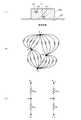
2−1.外観構成
図2(1)は、温度測定装置1の全体構成例を示す外観図である。本実施例における温度測定装置1は、装置本体10に設けられた2本のバンド20,20をバックル21で留めることで、被測定体であり人体であるユーザーの腕に装着される腕時計型のウェアラブル機器として構成される。2本のバンド20,20をユーザーの腕に巻き付けることで装置本体10の裏面(接触面)を、ユーザーの皮膚面に密着させることができる。なお、装着部位は腕に限らず、胸部や腹部、首部、大腿部、足首等の別の部位の皮膚面に装着する構成としてもよい。また、手首のみならず、上腕に到着する構成としてもよい。装着部位に応じてバンド20を長尺としたり、バンド20の一部を伸縮素材としたり、バックル21の代わりに面ファスナー等を用いたりすると好適である。勿論、本実施例においてもバックル21の代わりに面ファスナーを用いてもよい。2-1. External Configuration FIG. 2A is an external view showing an example of the overall configuration of the
温度測定装置1は、装置本体10の表側(ユーザーに装着した時に外向きになる側)に表示面を有する表示部13と、操作入力手段としての操作スイッチ16とを備える。ユーザーは、操作スイッチ16を操作して測定開始操作等の各種操作入力をすることができる。また、装置本体10の内部には、充電式のバッテリー15と、制御基板17とが内蔵される。なお、図示しないが、その他にも、装置本体10の適所において、内部温度の測定結果を外部装置に送信等するための通信装置や、測定結果をメモリーカードに読み書き等するためのリーダーライター装置等が適宜設けられる。 The
バッテリー15への充電方式は適宜設定できる。例えば、装置本体10の背面側に電気接点を別途設け、家庭用電源に接続されたクレードルにセットし、電気接点を介してクレードル経由で通電・充電される構成でもよいし、非接触式の無線式充電でもよい。 The charging method for the
制御基板17には、CPU(Central Processing Unit)171と、IC(Integrated Circuit)メモリー等の記憶素子でなる記憶媒体173とが搭載されている。その他にも、ASIC(Application Specific Integrated Circuit)やFPGA(Field-Programmable Gate Array)、各種集積回路等の必要な電子部品を適宜搭載することができる。温度測定装置1は、CPU171が記憶媒体173に格納されているプログラムを実行することによって、内部温度の測定機能等の各種機能を実現する。 On the
表示部13は、液晶表示装置や電気泳動装置、有機EL(Electro Luminescence)ディスプレー等の小型ディスプレーで構成される。また、タッチパネル機能を備えることとしてもよい。 The
図2(2)は、装置本体10の厚み方向断面における、第1温度センサー11および第2温度センサー12の配置位置を説明するための簡略図である。装置本体10の厚み方向において、ユーザーの皮膚に接触する装置本体10の裏面である接触面10b寄りに第1温度センサー11が配置され、表示部13寄りに第2温度センサー12が配置されている。より詳細には、第1温度センサー11は、表示部13よりも接触面10bに近い位置に配置されており、第2温度センサー12は、接触面10bよりも表示部13に近い位置に配置されている。 FIG. 2B is a simplified diagram for explaining the arrangement positions of the
図2(3)は、装置本体10の平面視における表示部13の表示面13aと、第1温度センサー11および第2温度センサー12との位置関係を説明するための図である。表示部13には、内部温度の測定のために表示状態を変化させた状態であることを示すマークMを表示する部位が定められている。そのマークMの表示部位の下に第2温度センサー12が位置決めされ、第1温度センサー11はマークMから離れた位置に配置されている。 FIG. 2 (3) is a diagram for explaining the positional relationship between the
人体の内部温度が外界の温度よりも高い状況であれば、人体から装置本体10を通って、外界へ熱が放出される熱流経路が形成される。このとき、装置本体10の表面を通じて熱が放出されるため、装置本体10の表面の放射率が変化すれば、放出される熱も変化する。すなわち、表示部13の表示状態を変化させることで放射率を変化させ、熱収支特性を変化させるのが本実施例である。本実施例において表示状態の変化はマークMが担う。 If the internal temperature of the human body is higher than the external temperature, a heat flow path is formed through which heat is released from the human body through the apparatus
特に特徴的であるのは、本実施例では、第2温度センサー12は、ユーザーの皮膚面とマークMとの間であり、マークMの直下に位置決めされていることである。このため、第2温度センサー12の配置位置を経由する熱流経路は、マークMが表示されたり、非表示となったりすることで放射率の変化の作用を大きく受け、熱収支特性に影響が表れる。結果、マークMの表示/非表示によって、上述の原理で説明した「第1状態」と「第2状態」を比較的簡単に作り出すことができる。 In particular, in the present embodiment, the
また、本実施例では、放射率の変化の作用が一層明らかに表れるように、図2(3)に示すように、平面視におけるマークMの面積を、第2温度センサー12の面積の3倍以上としている。そして、第2温度センサー12の設置位置を、マークMの略中央の直下としている。 In this embodiment, the area of the mark M in plan view is three times the area of the
また、図2(3)に示すように、第1温度センサー11及び第2温度センサー12は、平面視において装置本体10の外縁及び中心からの距離が異なる位置に配置する。これにより、第1温度センサー11及び第2温度センサー12それぞれの位置における熱流出に係る抵抗を異ならせることができ、定常状態において、第1温度センサー11及び第2温度センサー12それぞれの検出温度を異ならせることができる。 Further, as shown in FIG. 2 (3), the
なお、本実施例では、第1温度センサー11及び第2温度センサー12の配置位置を、平面視において装置本体10の外縁及び中心からの距離が異なる位置とするが、装置本体10の外縁からの距離、或いは、装置本体10の中心からの距離の何れかが異なる位置としてもよい。 In the present embodiment, the arrangement positions of the
また、本実施例において表示状態の変化をマークMの表示/非表示で実現することとするが、表示面13aの全面や左下1/4画面を黒表示と白表示とで切り替えて表示する等、別の表示形態を採用することとしてもよい。 In this embodiment, the display state is changed by displaying / hiding the mark M, but the
2−2.機能構成
図3は、本実施例における温度測定装置1の概略構成の一例を示すブロック図である。温度測定装置1は、第1温度センサー11と、第2温度センサー12と、演算処理部300と、操作部400と、表示部13と、音出力部600と、通信部700と、記憶部800とを有する。2-2. Functional Configuration FIG. 3 is a block diagram showing an example of a schematic configuration of the
演算処理部300は、記憶部800に記憶されているシステムプログラム等の各種プログラムに従って、温度測定装置1の各部を統括的に制御する制御装置及び演算装置であり、例えばCPU(Central Processing Unit)やDSP(Digital Signal Processor)等のプロセッサーを有して構成される。 The
演算処理部300は、主要な機能部として、被測定体の温度を測定するための温度算出部320及び温度推定部340を有し、温度測定プログラム810に従って、図5を参照して後述する温度測定処理を実行する。また、時刻を計時するための計時機能等を有する。 The
温度算出部320は、表示部13の表示状態を変化させ、表示状態の変化の前後における第1温度センサー11及び第2温度センサー12からの温度検出信号が示す検出温度を用いて、上述した式(12)に従って温度を算出する。 The
温度推定部340は、異なるタイミング、具体的には前回の測定タイミングと今回の測定タイミングにおいて温度算出部320で算出された算出温度を用いて、式(13)に従って温度を推定する。なお、熱抵抗定数R及び熱容量定数C、或いは、R×Cの値(以下、包括して「推定用定数」という。)は初期設定され、記憶部800に推定用定数850として設定される。 The
本実施例では、温度推定部340は温度測定に当たって常時機能していることとする。そのため、温度推定部340によって推定された温度が、測定結果である出力温度として記憶部800の温度データ830(図4参照)に記憶される。 In the present embodiment, it is assumed that the
操作部400は、スイッチ等を有して構成される入力装置であり、押下されたスイッチの信号を演算処理部300に出力する。初期設定のための設定値を入力したり、温度測定の開始、終了といった各種指示操作を入力するために用いられる。 The
表示部13は、液晶表示装置や電気泳動装置、有機EL(Electro Luminescence)ディスプレー等の小型ディスプレーで構成され、演算処理部300から入力される表示信号に基づく各種表示を行う表示装置である。表示部13には、内部温度の測定のためのマークMや、測定結果である出力温度、非定常状態か定常状態かの測定状態の識別、測定した温度が異常であるか正常であるかの識別等が表示される。 The
音出力部600は、スピーカーを有して構成され、演算処理部300から入力される音信号に基づき音を再生して出力する。音出力部600は、測定した温度が異常であるか正常であるかの識別音や各種報知音等を出力する。ここで言う音には音声が含まれるのは勿論である。 The
通信部700は、演算処理部300の制御に従って、装置内部で利用される情報をPC(Personal Computer)等の外部の情報処理装置との間で送受するための通信装置である。この通信部700の通信方式としては、所定の通信規格に準拠したケーブルを介して有線接続する形式や、近距離無線通信を利用して無線接続する形式等、種々の方式を適用可能である。 The
記憶部800は、ROM(Read Only Memory)やフラッシュROM、RAM(Random Access Memory)等の記憶装置を有して構成される。記憶部800には、温度測定装置1のシステムプログラムや、温度算出機能、温度推定機能、通信機能等の各種機能を実現するための各種プログラム、データ等を記憶している。 The
記憶部800には、プログラムとして、演算処理部300によって読み出され、温度測定処理(図5参照)として実行される温度測定プログラム810が記憶されている。温度測定プログラム810には、上述した原理に従って温度を算出するための温度算出プログラム812と、温度を推定するための温度推定プログラム814とがサブルーチンとして含まれる。温度測定処理については、フローチャートを用いて詳細に後述する。 The
また、記憶部800には、データとして、温度データ830と、推定用定数850と、異常温度条件870と、正常復帰条件880と、測定時間間隔890とが記憶される。 In addition, the
温度データ830は、例えば、図4に示すデータ構造を有する。すなわち、表示部13のマークMを非表示とした第1表示状態かマークMを表示した第2表示状態かの識別情報と、第1温度センサー11及び第2温度センサー12から入力した温度検出信号に基づくそれぞれの検出温度と、この検出温度を用いて算出した算出温度と、この算出温度を用いて推定した、測定結果として出力する出力温度(出力値)と、測定状態が非定常状態か定常状態かを示す測定状態と、出力温度が正常であるか異常であるかの判定結果とを、各測定タイミングの時刻と対応づけて格納する。従って、温度データ830は、各値の履歴データとも言える。 The
ここで、時刻は、温度測定が行われた時刻(タイミング)を意味する。また、測定状態は、算出温度の変化経過に基づき判定される。例えば前後の算出温度の温度差と算出時間間隔とから温度変化速度を求め、これが一定値以内に収まった場合に定常状態と判定し、それまでは非定常状態と判定する。
なお、図4において、初回の時刻「T1」においては、表示状態を一定とした1回分の検出温度しか得られていないため、温度を算出することができず、算出温度、出力温度、測定状態、判定結果が何れも空欄となっている。Here, the time means the time (timing) when the temperature measurement is performed. Further, the measurement state is determined based on the change of the calculated temperature. For example, the temperature change speed is obtained from the temperature difference between the calculated temperatures before and after and the calculation time interval, and when this is within a certain value, it is determined as a steady state, and until then, it is determined as an unsteady state.
In FIG. 4, at the first time “T1”, since only one detection temperature with a constant display state is obtained, the temperature cannot be calculated, and the calculated temperature, output temperature, measurement state The determination results are all blank.
図3に戻り、異常温度条件870は、出力温度が異常であることを判断するための条件である。例えば、高温側の条件(例えば38度以上)と、低温側の条件(例えば27度以下)とをOR条件で含む条件とする。高温になった場合、低温になった場合の何れの場合も異常と判断する。 Returning to FIG. 3, the
正常復帰条件880は、異常温度条件870を満たすために異常と判断された後に、出力温度が正常温度に戻ったことを判断するための条件である。正常復帰条件880には、温度に関する条件(復帰温度条件)と、時間に関する条件(復帰時間条件)とが含まれる。復帰温度条件は、異常温度条件870の閾値よりも正常値に近い閾値が条件とされる。例えば、高温側の条件として37.5度未満であるとし、低温側の条件として30度以上として、この温度範囲内であることを復帰温度条件とする。復帰時間条件は、復帰温度条件を満たした状態が継続して一定時間経過したことを判断するための条件であり、例えば、1分以上といった条件が定められる。復帰温度条件を満たした状態の継続時間が復帰時間条件を満たしたこと、これが正常復帰条件880となる。 The
測定時間間隔890は、温度測定を行う時間間隔である。測定状態が定常状態か非定常状態(過渡状態)か、判定結果が正常判定(正常温度)か異常判定(異常温度)かによって、測定時間間隔890が変更される。具体的には、非定常状態であれば、定常状態よりも短く設定される。また、異常判定であれば、正常判定よりも短く設定される。 The
なお、測定時間間隔890の設定はこれに限らない。正常判定、または定常状態が継続する場合には所定の最大時間間隔まで徐々に長くしてもよい。また、判定結果が正常判定から異常判定に変化した場合には、所定の最小時間間隔に切り替え、異常判定が継続する場合には、徐々に所定の異常時時間間隔まで長くすることとしてもよい。また、測定開始時には測定時間間隔を最小時間間隔とし、非定常状態の間、非定常状態が継続する時間に応じて、徐々に所定の非定常時標準時間間隔まで長くすることとしてもよい。時間間隔が長くなることで省電力となる。 The setting of the
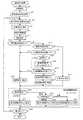
2−2.温度測定処理の流れ
図5は、演算処理部300が、記憶部800に記憶されている温度測定プログラム810に従って実行する温度測定処理の流れを示すフローチャートである。2-2. Flow of Temperature Measurement Process FIG. 5 is a flowchart showing the flow of the temperature measurement process executed by the
まず、演算処理部300は、初期設定を行う(ステップA1)。例えば、温度測定の終了条件として、測定回数や、温度測定処理を継続する時間を設定することができる。 First, the
次いで、演算処理部300が、第1温度センサー11及び第2温度センサー12の検出温度を取得して、温度データ830に記憶させる(ステップA3)。初回の検出温度となるため、内部温度の算出までは行わない。 Next, the
次いで、演算処理部300は、表示部13の表示状態を変更させる(ステップA5)。直前の表示状態がマークMを表示させていない状態であればマークMを表示させ、表示させた状態であればマークMを非表示とする。これにより、第1表示状態と第2表示状態とを切り替える。また、表示状態を変更したため、所定時間の間、処理を移行せずに待機する。待機時間は装置本体10の放射率が変わることを担保する時間となり、装置本体10の材質等に応じて、例えば5秒〜5分程度の間で適宜設定することができる。 Next, the
次いで、演算処理部300は、第1温度センサー11及び第2温度センサー12の検出温度を取得し、温度データ830に記憶させるとともに、今回の検出温度と前回の測定タイミングでの検出温度とを用いて、内部温度を算出する(ステップA7)。また、演算処理部300は、前回の測定タイミングで算出した算出温度と、今回の測定タイミングで算出した算出温度とを用いて、内部温度を推定する(ステップA7)。この推定後の温度(推定温度)を、今回の測定タイミングでの測定結果とし、出力温度として温度データ830に記憶させる。また、出力温度を求めるまでの課程で求めた算出温度も測定時刻と対応づけて温度データ830に記憶させる。 Next, the
次いで、演算処理部300は、算出温度の経過に基づき、測定状態を判定し、温度データ830に記憶させる(ステップA9)。そして、出力温度を表示部13に表示させる(ステップA11)。このとき、判定した測定状態を表示させることとしてもよい。 Next, the
出力温度が、異常温度条件870を満たす場合には(ステップA13:YES)、演算処理部300は、温度が異常であると判定して、異常温度である旨の報知を行う(ステップA15)。また、異常温度条件870を満たさない場合には(ステップA13:NO)、前回の測定タイミングの測定結果が異常判定であったか否かを判断する(ステップA17)。前回が異常判定であった場合には(ステップA17:YES)、今回の出力温度が正常復帰条件880のうちの復帰温度条件を満たすかを判断する(ステップA19)。ここで否定判断となった場合(ステップA19:NO)は、異常判定される(ステップA15)。この場合、今回の出力温度は異常温度ではないが、前回の判定が異常判定であり、異常温度でないと継続して言えるまでは、異常と判定することを意味する。 When the output temperature satisfies the abnormal temperature condition 870 (step A13: YES), the
また、復帰温度条件を満たすと判定された場合(ステップA19:YES)、復帰温度条件を満たすと判定されている状態の継続時間を計時する(ステップA21〜A23)。すなわち、当該時間を計時中でなければ、経過時間の計時をリセットしてスタートする。 If it is determined that the return temperature condition is satisfied (step A19: YES), the duration of the state in which it is determined that the return temperature condition is satisfied is measured (steps A21 to A23). That is, if the time is not being measured, the elapsed time is reset and started.
そして、計時している経過時間が復帰時間条件を満たす場合(ステップA25:YES)には、経過時間の計時を停止し(ステップA27)、正常温度に復帰したと判定して、その旨を報知する(ステップA29)。復帰時間条件を満たさない場合には(ステップA25:NO)、引き続き異常判定として(ステップA15)、様子見とする。 If the elapsed time being measured satisfies the return time condition (step A25: YES), the elapsed time measurement is stopped (step A27), and it is determined that the normal temperature has been restored, and this is notified. (Step A29). When the return time condition is not satisfied (step A25: NO), the abnormality determination is continued (step A15) and the state is viewed.
また、ステップA17において、前回の判定結果が異常ではない場合には(ステップA17:NO)、正常と判定して、その旨を報知する(ステップA31)。 In step A17, if the previous determination result is not abnormal (step A17: NO), it is determined to be normal and a notification to that effect is given (step A31).
ステップA15,A29,A31の何れかの後、演算処理部300は、測定時間間隔890を設定する。すなわち、測定状態が非定常状態である場合には(ステップA33:非定常状態)、時間間隔It1を測定時間間隔890に設定する(ステップA37)。また、定常状態である場合には(ステップA33:定常状態)、判定結果が異常判定であれば時間間隔It2を、正常判定であれば時間間隔It3を測定時間間隔890に設定する(ステップA39,A41)。時間間隔は、It1<It2<It3である。After any of steps A15, A29, and A31,
そして、演算処理部300は、温度測定処理を終了するかを判定し、終了しない場合には(ステップS43:NO)、設定した測定時間間隔890に従って、次回の測定タイミングに達したときにステップA5に処理を移行し、温度測定を終了すると判断した場合には(ステップS43:YES)、温度測定処理を終了する。 Then, the
2−3.作用効果
以上、温度測定装置1によれば、装置本体10の厚み方向において被測定体への接触面10b寄りに第1温度センサー11が、表示部13寄りに第2温度センサー12が配置されている。そして、表示部13が第1表示状態のときの第1温度センサー11によって検出された第1状態第1温度および第2温度センサー12によって検出された第1状態第2温度と、第2表示状態のときの第1温度センサー11によって検出された第2状態第1温度および第2温度センサー12によって検出された第2状態第2温度とを用いて、被測定体の内部温度が算出される。表示部13の表示状態を異ならせることによって放射率が変わる。これにより、装置本体10を介した熱収支特性が変化し、少なくとも第2温度センサー12が位置する温度が変化する。2-3. As described above, according to the
また、内部温度は式(12)を用いて算出される。これにより、熱収支特性を判定する必要がないため、被測定体の内部温度を精確に求めることができる。 Further, the internal temperature is calculated using Expression (12). Thereby, since it is not necessary to determine a heat balance characteristic, the internal temperature of a to-be-measured body can be calculated | required correctly.
また、第2温度センサー12は、第1表示状態と第2表示状態とで表示色が変化するマークMの下に位置決めされている。これによれば、第2温度センサー12は、表示部13の表示状態が変わることで放射率が変わる作用を大きく受けることができる。 The
また、温度測定に当たっては、装置本体10の温度が定常状態に至っていない、非定常状態(過渡状態)の場合を考慮して、一旦「算出」した温度から、定常状態の温度を「推定」する。これにより、装置本体10を皮膚面に接触させて間もない非定常状態(過渡状態)であっても、精度の高い内部温度を求めることができる。 Further, in the temperature measurement, the temperature of the
3.変形例
本発明を適用した実施形態の一例を説明したが、本発明を適用可能な形態は上述した形態に限られるものではない。3. Although an example of an embodiment to which the present invention is applied has been described, the form to which the present invention can be applied is not limited to the above-described form.
例えば、温度測定装置1をバンド20,20で人体に装着・固定するウェアラブル機器として説明したが、スマートグラスとして構成することも可能である。その場合、メガネフレームのモダン(先セル)部分やテンプル部分等の皮膚に接触する部位に第1温度センサー11及び第2温度センサー12を内蔵することとし、皮膚への接触面と反対側の外面に表示画面を備える構成とする。より具体的には、当該部位の厚み方向において皮膚への接触面寄りに第1温度センサー11を備え、表示部寄りに第2温度センサー12を備える構成とする。表示状態の制御や温度の算出については、上述した実施形態と同様である。 For example, although the
また、上述した実施形態では、温度センサーを2つとして説明したが、3以上の温度センサーを用いる構成も可能である。例えば、上述した第1温度センサー11の近傍位置に複数の温度センサーを配置して、これらの温度センサーの検出温度のうちの中央値或いは平均値を、第1温度センサー11の位置の検出温度として採用することとする。同じく、上述した第2温度センサー12の近傍位置に複数の温度センサーを配置して、これらの温度センサーの検出温度のうちの中央値或いは平均値を、第2温度センサー12の位置の検出温度として採用する。 In the above-described embodiment, two temperature sensors have been described, but a configuration using three or more temperature sensors is also possible. For example, a plurality of temperature sensors are arranged in the vicinity of the
1 温度測定装置、 10 装置本体、 11 第1温度センサー、 12 第2温度センサー、 13 表示部、 300 演算処理部、 800 記憶部 DESCRIPTION OF
Claims (10)
Translated fromJapanese装置本体の厚み方向において被測定体への接触面寄りに配置された第1温度センサーと、
装置本体の厚み方向において前記表示部寄りに配置された第2温度センサーと、
前記表示部が第1表示状態のときの前記第1温度センサーによって検出された第1状態第1温度および前記第2温度センサーによって検出された第1状態第2温度と、前記表示部が第2表示状態のときの前記第1温度センサーによって検出された第2状態第1温度および前記第2温度センサーによって検出された第2状態第2温度とを用いて、前記被測定体の内部温度を算出する演算処理部と、
を備えた温度測定装置。A display unit;
A first temperature sensor disposed near the contact surface with the object to be measured in the thickness direction of the apparatus body;
A second temperature sensor disposed closer to the display unit in the thickness direction of the apparatus body;
The first state first temperature detected by the first temperature sensor and the first state second temperature detected by the second temperature sensor when the display unit is in the first display state, and the display unit is second Using the second state first temperature detected by the first temperature sensor in the display state and the second state second temperature detected by the second temperature sensor, the internal temperature of the measured object is calculated. An arithmetic processing unit to perform,
A temperature measuring device equipped with.
請求項1に記載の温度測定装置。The second temperature sensor is disposed below a portion of the display unit where a display color changes between the first display state and the second display state.
The temperature measuring device according to claim 1.
請求項2に記載の温度測定装置。The display unit and the second temperature sensor are configured such that an area of the portion of the display unit is larger than an area of the second temperature sensor in a plan view.
The temperature measuring device according to claim 2.
請求項3に記載の温度測定装置。The display unit and the second temperature sensor are configured such that the area of the portion of the display unit in plan view is three times or more the area of the second temperature sensor.
The temperature measuring device according to claim 3.
請求項1〜4の何れか一項に記載の温度測定装置。The first temperature sensor and the second temperature sensor are arranged at different positions from the outer edge or center of the apparatus main body in plan view.
The temperature measuring apparatus as described in any one of Claims 1-4.
請求項1〜5の何れか一項に記載の温度測定装置。
Tc=(Ta1・Tb2−Tb1・Ta2)/(Ta1−Ta2−Tb1+Tb2)
但し、Tcは内部温度、Ta1は第1状態第1温度、Ta2は第2状態第1温度、Tb1は第1状態第2温度、Tb2は第2状態第2温度。The arithmetic processing unit calculates the internal temperature of the measured object based on the following equation:
The temperature measuring apparatus as described in any one of Claims 1-5.
Tc = (Ta1 · Tb2 −Tb1 · Ta2 ) / (Ta1 −Ta2 −Tb1 + Tb2 )
However, Tc is the internal temperature, Ta1 is the first state first temperature, Ta2 is the second state first temperature, Tb1 is the first state second temperature, and Tb2 is the second state second temperature.
ウェアラブル機器として構成された、
請求項1〜6の何れか一項に記載の温度測定装置。The measured body is a human body,
Configured as a wearable device,
The temperature measuring device according to any one of claims 1 to 6.
請求項1〜7の何れか一項に記載の温度測定装置。The display unit includes a liquid crystal display device.
The temperature measuring device according to any one of claims 1 to 7.
請求項1〜7の何れか一項に記載の温度測定装置。The display unit includes an electrophoresis device.
The temperature measuring device according to any one of claims 1 to 7.
前記表示部を第1表示状態と第2表示状態とに切り替えることと、
前記第1表示状態のときの前記第1温度センサーによって検出された第1状態第1温度および前記第2温度センサーによって検出された第1状態第2温度と、前記第2表示状態のときの前記第1温度センサーによって検出された第2状態第1温度および前記第2温度センサーによって検出された第2状態第2温度とを用いて、前記被測定体の内部温度を算出することと、
を含む温度測定方法。A display unit; a first temperature sensor disposed near the contact surface with the measurement object in the thickness direction of the apparatus main body; and a second temperature sensor disposed near the display unit in the thickness direction of the apparatus main body. A temperature measurement method using a temperature measurement device,
Switching the display unit between a first display state and a second display state;
The first state first temperature detected by the first temperature sensor in the first display state and the first state second temperature detected by the second temperature sensor, and the first state detected in the second display state Using the second state first temperature detected by the first temperature sensor and the second state second temperature detected by the second temperature sensor to calculate the internal temperature of the measured object;
A temperature measurement method including:
Priority Applications (4)
| Application Number | Priority Date | Filing Date | Title |
|---|---|---|---|
| JP2015045041AJP2016164525A (en) | 2015-03-06 | 2015-03-06 | Temperature measuring apparatus and temperature measuring method |
| CN201610121982.9ACN105938020B (en) | 2015-03-06 | 2016-03-03 | Temperature measuring apparatus and temperature-measuring method |
| EP16158706.8AEP3064917B1 (en) | 2015-03-06 | 2016-03-04 | Temperature measurement apparatus and temperature measurement method |
| US15/061,334US9952105B2 (en) | 2015-03-06 | 2016-03-04 | Temperature measurement apparatus and temperature measurement method |
Applications Claiming Priority (1)
| Application Number | Priority Date | Filing Date | Title |
|---|---|---|---|
| JP2015045041AJP2016164525A (en) | 2015-03-06 | 2015-03-06 | Temperature measuring apparatus and temperature measuring method |
Publications (1)
| Publication Number | Publication Date |
|---|---|
| JP2016164525Atrue JP2016164525A (en) | 2016-09-08 |
Family
ID=55484872
Family Applications (1)
| Application Number | Title | Priority Date | Filing Date |
|---|---|---|---|
| JP2015045041APendingJP2016164525A (en) | 2015-03-06 | 2015-03-06 | Temperature measuring apparatus and temperature measuring method |
Country Status (4)
| Country | Link |
|---|---|
| US (1) | US9952105B2 (en) |
| EP (1) | EP3064917B1 (en) |
| JP (1) | JP2016164525A (en) |
| CN (1) | CN105938020B (en) |
Cited By (1)
| Publication number | Priority date | Publication date | Assignee | Title |
|---|---|---|---|---|
| JP2021156887A (en)* | 2020-03-27 | 2021-10-07 | メソード・エレクトロニクス・マルタ・リミテッドMethode Electronics Malta Ltd. | Device for monitoring set of bearings |
Families Citing this family (12)
| Publication number | Priority date | Publication date | Assignee | Title |
|---|---|---|---|---|
| DE112017002805T5 (en)* | 2016-06-03 | 2019-02-28 | Mitsubishi Electric Corporation | Equipment control device and equipment control method |
| WO2019063519A1 (en) | 2017-09-27 | 2019-04-04 | Abb Schweiz Ag | TEMPERATURE MEASURING DEVICE AND METHOD FOR TEMPERATURE DETERMINATION |
| DE102018119857A1 (en) | 2018-08-15 | 2020-02-20 | Abb Schweiz Ag | Temperature measuring device and method for temperature determination |
| CN112577611B (en)* | 2019-09-29 | 2022-10-04 | 华为技术有限公司 | Human body temperature measurement method, electronic device and computer-readable storage medium |
| CN111596745B (en)* | 2020-05-13 | 2022-03-01 | 歌尔科技有限公司 | Temperature detection device, method and system and electronic equipment |
| CN111473888B (en)* | 2020-05-22 | 2021-12-10 | 杭州谋定智能科技有限公司 | Thermometer and method for calculating core body temperature based on wrist body temperature |
| CN112050950B (en)* | 2020-10-09 | 2021-09-24 | 浙江福祉科创有限公司 | Wearable device and human body temperature measuring method for same |
| JP7080368B1 (en)* | 2021-03-18 | 2022-06-03 | 三菱電機株式会社 | Control device and control method |
| CN114300088B (en)* | 2021-12-15 | 2023-06-16 | 苏州大学附属第二医院 | Body temperature monitoring device and system for guiding perimenopausal hormone replacement therapy |
| US20240060832A1 (en)* | 2022-08-18 | 2024-02-22 | Apple Inc. | Dual heat path temperature sensor |
| KR20240073613A (en)* | 2022-11-18 | 2024-05-27 | 삼성전자주식회사 | Electronic device and method for measuring skin surface temperature using thereof |
| DE102023123698A1 (en)* | 2023-09-04 | 2024-10-24 | Schaeffler Technologies AG & Co. KG | Method for determining a surface temperature of a component and measuring device for carrying out the method |
Family Cites Families (19)
| Publication number | Priority date | Publication date | Assignee | Title |
|---|---|---|---|---|
| JPS5529794A (en) | 1979-07-14 | 1980-03-03 | Terumo Corp | Temperature detector for deep-part temperature measurement |
| US6220750B1 (en)* | 1999-03-29 | 2001-04-24 | Yoram Palti | Non-invasive temperature measurement method and apparatus |
| US7938783B2 (en)* | 2003-08-19 | 2011-05-10 | Advanced Monitors Corporation | Medical body core thermometer |
| JP4600170B2 (en)* | 2004-09-15 | 2010-12-15 | セイコーエプソン株式会社 | Thermometer and electronic device having thermometer |
| US7981046B2 (en)* | 2007-09-10 | 2011-07-19 | Medisim Ltd | Temperature measurement device |
| US8226294B2 (en)* | 2009-08-31 | 2012-07-24 | Arizant Healthcare Inc. | Flexible deep tissue temperature measurement devices |
| JP5402735B2 (en)* | 2010-03-10 | 2014-01-29 | セイコーエプソン株式会社 | Thermometer and temperature measurement method |
| JP5732737B2 (en)* | 2010-04-02 | 2015-06-10 | セイコーエプソン株式会社 | Temperature measuring apparatus and temperature measuring method |
| US8292495B2 (en)* | 2010-04-07 | 2012-10-23 | Arizant Healthcare Inc. | Zero-heat-flux, deep tissue temperature measurement devices with thermal sensor calibration |
| JP5578029B2 (en)* | 2010-10-29 | 2014-08-27 | セイコーエプソン株式会社 | Temperature measuring apparatus and temperature measuring method |
| JP5578028B2 (en)* | 2010-10-29 | 2014-08-27 | セイコーエプソン株式会社 | Temperature measuring apparatus and temperature measuring method |
| BR112013020849A2 (en)* | 2011-02-16 | 2018-05-29 | Arizant Healthcare Inc | zero heat flow temperature device, temperature measurement device, temperature measurement system, body temperature measurement methods |
| US9354122B2 (en)* | 2011-05-10 | 2016-05-31 | 3M Innovative Properties Company | Zero-heat-flux, deep tissue temperature measurement system |
| JP5821449B2 (en) | 2011-09-13 | 2015-11-24 | セイコーエプソン株式会社 | Temperature measurement system and temperature calculation method |
| US8687026B2 (en)* | 2011-09-28 | 2014-04-01 | Apple Inc. | Systems and method for display temperature detection |
| JP6337416B2 (en) | 2013-03-12 | 2018-06-06 | セイコーエプソン株式会社 | Temperature measuring device |
| JP6442826B2 (en)* | 2013-12-27 | 2018-12-26 | セイコーエプソン株式会社 | Blood component analysis method and blood component analyzer |
| JP2016057199A (en)* | 2014-09-10 | 2016-04-21 | セイコーエプソン株式会社 | Temperature measuring apparatus and temperature measuring method |
| CN104792439B (en)* | 2015-04-09 | 2018-07-24 | 杨松 | Thermometry, device, probe and system |
- 2015
- 2015-03-06JPJP2015045041Apatent/JP2016164525A/enactivePending
- 2016
- 2016-03-03CNCN201610121982.9Apatent/CN105938020B/enactiveActive
- 2016-03-04USUS15/061,334patent/US9952105B2/enactiveActive
- 2016-03-04EPEP16158706.8Apatent/EP3064917B1/enactiveActive
Cited By (2)
| Publication number | Priority date | Publication date | Assignee | Title |
|---|---|---|---|---|
| JP2021156887A (en)* | 2020-03-27 | 2021-10-07 | メソード・エレクトロニクス・マルタ・リミテッドMethode Electronics Malta Ltd. | Device for monitoring set of bearings |
| JP7447048B2 (en) | 2020-03-27 | 2024-03-11 | メソード・エレクトロニクス・マルタ・リミテッド | Device for monitoring bearing sets |
Also Published As
| Publication number | Publication date |
|---|---|
| US9952105B2 (en) | 2018-04-24 |
| US20160258823A1 (en) | 2016-09-08 |
| CN105938020A (en) | 2016-09-14 |
| CN105938020B (en) | 2019-08-23 |
| EP3064917A1 (en) | 2016-09-07 |
| EP3064917B1 (en) | 2019-01-09 |
Similar Documents
| Publication | Publication Date | Title |
|---|---|---|
| CN105938020B (en) | Temperature measuring apparatus and temperature-measuring method | |
| JP6337416B2 (en) | Temperature measuring device | |
| JP6763142B2 (en) | Internal temperature measuring device, wrist-mounted device and internal temperature measuring method | |
| JP7549893B2 (en) | DEVICES, SYSTEMS, AND METHODS FOR NON-INVASIVE THERMAL INTERROGATION | |
| JP2016057199A (en) | Temperature measuring apparatus and temperature measuring method | |
| JP3909301B2 (en) | Body temperature information terminal device and body temperature information processing system | |
| JP5821449B2 (en) | Temperature measurement system and temperature calculation method | |
| CN111741710B (en) | Core temperature detection system and method | |
| JP2017055968A (en) | Temperature measuring apparatus and temperature measuring method | |
| JP2016109518A (en) | Temperature measurement device and temperature measurement method | |
| CN109154527A (en) | Calibrate the heat flux sensor for measuring individual body temperature | |
| JP5971394B2 (en) | Temperature measurement system and temperature calculation method | |
| CN113125014A (en) | Infrared body temperature measuring method, electronic equipment and readable storage medium | |
| CN105852801A (en) | Vaporization heat quantity measuring device, biological information measuring device, and electronic apparatus | |
| EP4372341A1 (en) | Electronic device and method of estimating skin surface temperature using the same | |
| JP5780340B2 (en) | Temperature measuring apparatus and temperature measuring method | |
| JP2019166117A (en) | Body temperature measurement processing program, body temperature measurement device and body temperature measurement processing system comprising the program | |
| JP2016087304A (en) | Evaporation heat loss amount measuring apparatus, metabolic amount measuring apparatus, and evaporation heat loss amount measuring method | |
| JP2021026498A (en) | Preventive action support device and program | |
| TWI745720B (en) | System and method for enhancing accuracy of body surface temperature measurement | |
| JP2019178914A (en) | Body temperature measurement processing program, body temperature measuring device having the program, and body temperature measurement processing system | |
| JP2019055087A (en) | Living body analyzer and living body analysis method | |
| CN111473888B (en) | Thermometer and method for calculating core body temperature based on wrist body temperature | |
| US20230172456A1 (en) | Installation State Determination Method, and Installation State Determination System | |
| JP2014221160A (en) | Activity meter |