JP2016164010A - In-vehicle camera system - Google Patents
In-vehicle camera systemDownload PDFInfo
- Publication number
- JP2016164010A JP2016164010AJP2015044218AJP2015044218AJP2016164010AJP 2016164010 AJP2016164010 AJP 2016164010AJP 2015044218 AJP2015044218 AJP 2015044218AJP 2015044218 AJP2015044218 AJP 2015044218AJP 2016164010 AJP2016164010 AJP 2016164010A
- Authority
- JP
- Japan
- Prior art keywords
- vehicle
- power supply
- camera
- shift position
- vehicle camera
- Prior art date
- Legal status (The legal status is an assumption and is not a legal conclusion. Google has not performed a legal analysis and makes no representation as to the accuracy of the status listed.)
- Pending
Links
Images


Landscapes
- Closed-Circuit Television Systems (AREA)
Abstract
Description
Translated fromJapanese本発明は、車載カメラシステムに関する。 The present invention relates to an in-vehicle camera system.
車両に搭載されるリアカメラは、オートマチックトランスミッションのシフトレバーのシフトポジションが、「リバースポジション(後退)」に切り替わったことが検知されることで電源供給が開始され、車両後方の撮像を開始することができる。通常、電源供給開始から車両後方の映像が出力(表示)されるまでに要する時間は0.5秒程度であり、この起動時間の短縮が望まれている。 The rear camera installed in the vehicle starts power supply when it detects that the shift position of the shift lever of the automatic transmission has been switched to "reverse position (reverse)" and starts imaging the rear of the vehicle. Can do. Usually, the time required from the start of power supply to the output (display) of the image behind the vehicle is about 0.5 seconds, and it is desired to shorten the activation time.
例えば、特許文献1に、エンジン始動と同時に、バックカメラ(リアカメラ)に電源を投入し、車両が一定速度で一定距離を走行したときに電源を切断することで、シフトレバーがリバースポジション切り替えられる前にバックカメラの電源を投入される様にし、画像が出力されるまでの時間短縮をはかる技術が記載されている。 For example, in Patent Document 1, when the engine is started, the power is turned on to the back camera (rear camera), and the shift lever is switched to the reverse position by turning off the power when the vehicle travels a certain distance at a constant speed. A technique is described in which the power of the back camera is turned on before and the time until the image is output is shortened.
特許文献1に開示された技術によれば、エンジン始動時以外の、例えば、通常走行からバック走行に切り替わるときに、リアカメラはシフトレバーがリバースポジションに切り替えられたことと連動して電源供給されるため起動時間の短縮ができない。通常バック走行を行うとき、通常走行からバック走行に切り替わるシーンが多いと考えられるため、依然として問題は解決されていない。 According to the technique disclosed in Patent Document 1, when the engine is switched from the normal travel to the back travel, for example, when the engine is started, the rear camera is supplied with power in conjunction with the shift lever being switched to the reverse position. Therefore, the startup time cannot be shortened. When performing normal back travel, it is considered that there are many scenes where the normal travel is switched to the back travel, so the problem has not been solved.
本発明は上記した課題を解決するためになされたものであり、車載カメラへの電源供給開始から映像信号出力までに要する時間の短縮をはかった車載カメラシステムを提供することを目的とする。 The present invention has been made to solve the above-described problems, and an object of the present invention is to provide an in-vehicle camera system that shortens the time required from the start of power supply to the in-vehicle camera to the output of a video signal.
上記した課題を解決するために本発明の車載カメラシステムは、車載カメラと、
前記車載カメラに電源供給を行う電源回路部と、
前記車載カメラへの電源供給の開始及び停止の制御を前記電源回路部に対して行う制御部とを備え、前記制御部が前記車載カメラが搭載された車両のシフトレバーのシフトポジションが、ドライブからニュートラルに切り替わったことを検出したとき、または、直前のシフトポジションにかかわらずパーキングに切り替わったことを検出したとき、前記制御部は前記電源回路部から前記車載カメラへの電源供給を開始することを特徴とする。In order to solve the above-described problem, the in-vehicle camera system of the present invention includes an in-vehicle camera,
A power supply circuit unit for supplying power to the in-vehicle camera;
A control unit that controls start and stop of power supply to the in-vehicle camera with respect to the power circuit unit, and the control unit shifts a shift position of a shift lever of a vehicle on which the in-vehicle camera is mounted from a drive. When it is detected that the switch has been switched to neutral, or when it has been detected that the switch has been switched to parking regardless of the previous shift position, the control unit starts power supply from the power supply circuit unit to the vehicle-mounted camera. Features.
また、本発明の車載カメラシステムは、車載カメラと、前記車載カメラへ電源供給を行う電源回路部と、前記電源回路部に前記車載カメラへの電源供給を開始及び停止させる制御を行う制御部とを備え、車両のシフトポジションが、ドライブとニュートラルとの中間点を検出したとき、または、パーキングとリバースとの中間点を検出したとき、前記制御部は前記電源回路部から前記車載カメラへの前記電源供給を開始することを特徴とする。 The vehicle-mounted camera system of the present invention includes a vehicle-mounted camera, a power supply circuit unit that supplies power to the vehicle-mounted camera, and a control unit that controls the power supply circuit unit to start and stop power supply to the vehicle-mounted camera; When the vehicle shift position detects an intermediate point between drive and neutral, or when an intermediate point between parking and reverse is detected, the control unit transmits the power supply circuit unit to the in-vehicle camera. The power supply is started.
本発明において、前記制御部は、前記車両のシフトポジションが、前記パーキングまたは前記ニュートラルから前記リバースに一定時間切り替えが無いことを検出したときに、前記電源供給を停止させることを特徴とする。 In this invention, the said control part stops the said power supply, when it detects that the shift position of the said vehicle does not switch from the said parking or the said neutral to the said reverse for a fixed time.
本発明において、前記制御部は、コントロールエリアネットワーク(以下CAN(Control Area Network)とも言う)経由で取得されるトランスミッション系の信号から前記シフトポジションの切り替えを検出することを特徴とする。 In the present invention, the control unit detects switching of the shift position from a transmission system signal acquired via a control area network (hereinafter also referred to as CAN (Control Area Network)).
本発明によれば、車載カメラへの電源供給開始から映像信号出力までに要する時間の短縮をはかった車載カメラシステムを提供することができる。 ADVANTAGE OF THE INVENTION According to this invention, the vehicle-mounted camera system which aimed at shortening of the time required from the power supply start to a vehicle-mounted camera to video signal output can be provided.
以下、添付図面を参照して、本発明を実施するための形態(以下、本実施形態と言う)について詳細に説明する。なお、実施形態の説明の全体を通して同じ要素には同じ番号又は符号を付している。 DESCRIPTION OF EMBODIMENTS Hereinafter, a mode for carrying out the present invention (hereinafter referred to as this embodiment) will be described in detail with reference to the accompanying drawings. In addition, the same number or code | symbol is attached | subjected to the same element through the whole description of embodiment.
(実施形態の構成)
図1は、本実施形態に係る車載カメラシステム10が搭載される車両の電装系の接続構成が示されている。図1に示すように、車両には、複数の電子制御ユニット(ECU)が搭載されており、これらECUは、CANによる車載LANを介して接続され、ECU間で双方向にデータ通信を行う協調制御を実現している。なお、CANとは、車載機器間の通信技術として開発され、ISO(国際標準化機構)により規格化されたバス型のネットワーク通信規格(ISO11898またはISO11519)である。(Configuration of the embodiment)
FIG. 1 shows a connection configuration of an electrical system of a vehicle on which an in-
車両には、ECUとして、例えば、エンジン系の制御を行うエンジンECU、トランスミッション系の制御を行うトランスミッション系ECU、ブレーキ操作に応じた制御およびアンチロックブレーキ等の制動力制御を行う制動系ECU、空調の他、ナビゲーション装置、車載カメラ等、車載機器の制御を行う電装系のECU等が搭載されている。ここでは、ECUとして、車載カメラシステム10,トランスミッション系ECU11のみが例示されており、他は、総称してその他ECU12として示してある。ECU10,11,12は、CANバス14に接続され、車載カメラシステム10には更に車載カメラとしてリアカメラ13が接続されている。このリアカメラ13はここでは、車両後方の映像を撮影して車載カメラシステム10に映像信号を出力するものである。 In a vehicle, for example, an engine ECU that controls an engine system, a transmission system ECU that controls a transmission system, a braking system ECU that performs control according to a brake operation and braking force control such as an antilock brake, an air conditioner In addition, an electronic ECU that controls in-vehicle devices such as a navigation device and an in-vehicle camera is mounted. Here, only the in-
上記構成において、車載カメラシステム10は、トランスミッション系ECU11において、シフトレバーのシフトポジションが、「ドライブ」から「ニュートラル」に切り替わったことを検出したとき、または、直前のシフトポジションにかかわらず「パーキング」に切り替わったことを検出したときに、リアカメラ13に電源供給を開始する制御を行う。また、シフトポジションが「ドライブ」から「ニュートラル」に切り替わる中間点(例えば、「ドライブ」と「ニュートラル」の間にシフトポジションが位置している)を検出したとき、または、「パーキング」から「リバース」に切り替わる中間点を検出したときにリアカメラ13に電源供給を開始してもよい。 In the above-described configuration, the in-
また、車載カメラシステム10は、シフトポジションが、「パーキング」または「ニュートラル」から「リバース」に一定時間切り替えが無いことを検出したときに、電源供給を切断する制御を行う。これらの制御は、車載カメラシステム10が、CAN14経由で取得されるトランスミッション系(トランスミッションECU11)の信号からシフトポジションの切り替えを検出し、リアカメラ13に対して電源ON/OFF信号が供給することにより実行される。尚、シフトレバーのシフトポジションである「パーキング」は車両を駐車するときに車の移動をさせないポジションであり、「ドライブ」は車両を前進させるポジションであり、「ニュートラル」はエンジンの駆動力の車輪への伝達を切り離すポジションであり、「リバース」は車両を後退させるポジションである。これら各ポジションが車の前方から順に「パーキング」、「ドライブ」、「ニュートラル」、「リバース」の順に並んでおり、シフトレバーはこの間を遷移する。このシフトレバーとシフトポジションとの関係は、車速やエンジンの回転数に応じて変速比を自動的に切り替えるオートマチックトランスミッション(自動変速機)の場合である。 The in-
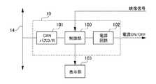
図2に、本実施形態に係る車載カメラシステム10の内部構成が示されている。図2によれば、本実施形態に係る車載カメラシステム10は、制御部100と、CANバスD/R(ドライバ/レシーバ)101と、電源回路部102とを含み構成される。 FIG. 2 shows an internal configuration of the in-
CANバスD/R101は、CANバス14と車載カメラシステム10の制御部100との間のインタフェースであり、両者でデータ通信を行う際に使用されるアドレス、データ等の各信号の増幅を行うドライバ/レシーバである。電源回路部102は、制御部100により制御され、リアカメラ13が動作に必要とする電源容量を持つ電源と、電源のリアカメラ13への供給、停止を行うスイッチとを含む。なお、電源回路部102は、図示省略したナビゲーション装置が持つ電源と共用してもよい。 The CAN bus D / R 101 is an interface between the
制御部100は、CANバス14,CANバスD/R101を介してトランスミッション系ECU11から出力されるシフトレバーがどのシフトポジションにあるかを示すシフトポジション信号が、「ドライブ」から「ニュートラル」に切り替わったことを検出したとき、または、直前のシフトポジションにかかわらず「パーキング」に切り替わったことを検出したときに電源回路部102に対し、リアカメラ13に電源供給を開始する制御を行う。また、シフトレバーのシフトポジションが「ドライブ」から「ニュートラル」に切り替わる中間点を検出したとき、または、「パーキング」から「リバース」に切り替わる中間点を検出したときにリアカメラ13に電源供給を開始してもよい。 In the
また、制御部100は、シフトポジションが、「パーキング」または「ニュートラル」から「リバース」に一定時間切り替えが無いことを検出したときに、電源回路部102に対し、リアカメラ13の電源供給を切断する制御を行う。なお、制御部100には、リアカメラ13から車両後方の撮影画像(映像信号)が供給され、その撮影画像は、制御部100に接続される表示部103に表示される。ここでは、表示部103は、図示を省略したナビゲーション装置が持つ、例えば、LCD(Liquid Crystal Dsplay)モニタを使用するものとし、CANバス14経由で取得される前述のシフトポジション信号により、モニタ画面(ナビゲーション映像)とカメラ画面(撮影画像)とが切り替え表示されるものとする。 Further, when the
(実施形態の動作)
図3は、本実施形態に係る車載カメラシステム10の動作を従来例と対比して示した動作タイミング図である。(Operation of the embodiment)
FIG. 3 is an operation timing chart showing the operation of the in-
図3において、横軸は、時間を示し、縦軸は、上から順に、(a)車両のシフトポジション、(b)リバース連動時のカメラ電源ON/OFF(従来)、(c)カメラ/映像出力(従来)、(d)カメラ電源ON/OFF(本実施形態)、(e)カメラ/映像出力(本実施形態)、(f)モニタ表示切り替えタイミング(従来例・本実施形態)のそれぞれを示す。 In FIG. 3, the horizontal axis indicates time, and the vertical axis indicates, in order from the top, (a) vehicle shift position, (b) camera power ON / OFF at the time of reverse interlocking (conventional), (c) camera / video. Output (conventional), (d) Camera power ON / OFF (this embodiment), (e) Camera / video output (this embodiment), (f) Monitor display switching timing (conventional example / this embodiment) Show.
以下、車両のシフトポジションが、「ドライブ(D)」から「ニュートラル(N)」に切り替わったとき、またはその中間点を検出したときにリアカメラ13の電源供給を開始するケースを実施例1とし、「パーキング(P)」から「リバース(R)」に切り替わる中間点を検出したときにリアカメラ13の電源供給を開始するケースを実施例2として詳細説明を行う。 Hereinafter, a case where the power supply of the
<実施例1>
以下、図3のタイミング図を参照しながら、実施例1の車載カメラシステム10の動作を従来例と比較しながら説明する。<Example 1>
Hereinafter, the operation of the in-
図3(a)、(b)に示すように、従来は、「ニュートラル(N)」から「リバース(R)」へのシフトポジションの切り替えを検出したタイミングでリアカメラ13のカメラ電源をONしており、その結果、図3(c)に示すように、運転者がシフトポジションを「リバース」に入れてから(リアカメラに電源の供給を開始してから)リアカメラ13の起動に0.4〜0.5秒を要し、車両後方の撮像画像を映像出力していた。これに対し、本実施形態に係る車載カメラシステム10は、図3(a)(d)に示すように、「ドライブ(D)」から「ニュートラル(N)」へシフトポジションの切り替えを検出したタイミング(図中、一点鎖線で示す)で、あるいは、「ドライブ(D)」から「ニュートラル(N)」に切り替わる中間点を検出したタイミング(図中、太実線で示す)でカメラ電源をONしている。図3(c)と図3(e)を比較すると、従来の映像出力のタイミング(太点線で示すリバース検出から0.4〜0.5秒後)に対し、本実施例で示す映像出力のタイミング(太実線で示す「ドライブ」と「ニュートラル」の中間点から0.4〜0.5秒後)となっており、映像出力のタイミングが早まっていることが分かる。 As shown in FIGS. 3A and 3B, conventionally, the camera power of the
このため、本実施形態に係る車載カメラシステム10は、制御部100が、CANバス14,CANバスD/R101を介してミッションECU11から出力されるシフトポジション信号が「ドライブ(D)」から「ニュートラル(N)」に切り替わったことを示したとき、または、「ドライブ(D)」から「ニュートラル(N)」に切り替わる中間点を示したときに、制御部100は電源回路部102に対し、リアカメラ13に電源供給を開始する制御を行う。但し、図3(f)に示すように、表示部103へのカメラ画像表示への切り替えは、「リバース(R)」を検出したタイミングとする。これは、運転者は、車両がバック走行時以外のタイミングではナビゲーション画面を必要とする理由による。 For this reason, in the in-
なお、制御部100は、シフトポジションが、「パーキング(P)」または「ニュートラル(N)」から「リバース(R)」に一定時間(例えば1分間)切り替えが無いことを検出したときに、電源回路部102を制御してリアカメラ13への電源供給を切断する。また、シフトポジションが「ドライブ(D)」に切り替わってから、例えば、1分以上経過後等のように、時間監視を行なうことで、ハンドル切り返し毎にリアカメラ13の電源ON/OFFが繰り返される事を回避することも可能である。 When the
なお、実施例1では、シフトポジションが「ドライブ(D)」から「ニュートラル(N)」に切り替わったことを検出したとき、またはその中間点を検出したときにリアカメラ13の電源供給を開始することとしたが、直前のシフトポジションにかかわらず「パーキング(P)」に切り替わったことを検出したときに電源供給を開始しても同様の効果が得られる。 In the first embodiment, power supply to the
上記した実施例1によれば、制御部100は、車両のシフトポジションが、「ドライブ(D)」から「ニュートラル(N)」に切り替わったとき、またはその中間点を検出したとき、もしくは、直前のシフトポジションにかかわらず「パーキング(P)」に切り替わったときにリアカメラ13の電源供給を開始することにより、映像出力開始に要する時間が短縮され、車両のシフトポジションがリバースポジション(R)に切り替わった直後に後方視界の監視が可能になる。 According to the first embodiment described above, the
<実施例2>
図4に、実施例2の車載カメラシステム10の動作タイミングを示す。実施例1同様、横軸は、時間を示し、縦軸は、上から順に、(a)シフトポジション、(b)カメラ電源ON/OFF、(c)カメラ/映像出力、(d)モニタ切り替えタイミングを示す。以下、図4のタイミング図を参照しながら、実施例2の車載カメラシステム10の動作について詳細に説明する。<Example 2>
FIG. 4 shows the operation timing of the in-
図4(a)(b)に示すように、実施例2は、シフトポジションが、「パーキング(P)」から「リバース(R)」に切り替わる中間点を検出したタイミング(図中、太実線で示す)でカメラ電源をONする例であり、図4(c)に示すように、0.4〜0.5秒のカメラ起動時間を経て映像信号出力を行っている。なお、図4(d)に示すように、モニタ表示切替えタイミングは、実施例1同様、「リバース(R)」を検出したタイミングとする。 As shown in FIGS. 4 (a) and 4 (b), in the second embodiment, the timing at which an intermediate point at which the shift position is switched from “parking (P)” to “reverse (R)” is detected (indicated by a bold solid line in the figure). In this example, the camera power is turned on. As shown in FIG. 4C, the video signal is output after a camera activation time of 0.4 to 0.5 seconds. As shown in FIG. 4D, the monitor display switching timing is the timing at which “reverse (R)” is detected as in the first embodiment.
このため、車載カメラシステム10の制御部100は、CANバス14,CANバスD/R101を介してミッションECU11から出力されるシフトポジション信号が、「パーキング(P)」から「リバース(R)」に切り替わる中間点を示したときに、電源回路部102を制御してリアカメラ13に電源供給を開始する制御を行う。但し、図4(d)に示すように、表示部103へのカメラ画像表示への切り替えは、「リバース(R)」を検出したタイミングとする。 Therefore, the
なお、実施例1同様、制御部100は、シフトポジションが、「パーキング(P)」または「ニュートラル(N)」から「リバース(R)」に一定時間(例えば1分間)切り替えが無いことを検出したときに、電源回路部102を制御してリアカメラ13への電源供給を切断する。また、シフトポジションが「ドライブ(D)」に切り替わってから1分以上経過後等のように、時間監視を行なうことで、ハンドル切り返し毎の電源OFFを回避することも可能である。 As in the first embodiment, the
上記した実施例2によれば、制御部100は、車両のシフトポジションが、「パーキング(P)」から「リバース(R)」に切り替わる中間点を検出したときに、リアカメラ13の電源供給を開始することで映像出力開始が早まり、車両が「リバース(R)」に切り替わった直後に後方視界の監視が可能になる。図4(a)に太点線で示すように、「ニュートラル(N)」から「リバース(R)」へシフトポジションの切り替えを検出したタイミングでリアカメラ13のカメラ電源をONしていた従来例と比較して映像出力のタイミングが早まり、見かけ上の起動時間が速くなる。 According to the second embodiment described above, the
(実施形態の効果)
以上説明のように本実施形態に係る車載カメラシステム10によれば、制御部100が、車両のシフトポジションにおいて、シフトポジションが「ドライブ(D)」から「ニュートラル(N)」に切り替わったことを検出したとき、または、直前のシフトポジションにかかわらず「パーキング(P)」に切り替わったことを検出したときに制御部100が電源回路部102を制御してリアカメラ13への電源供給を開始することにより、あるいは、「ドライブ」から「ニュートラル」に切り替わる中間点を検出したとき、または、「パーキング」から「リバース」に切り替わる中間点を検出したときに、電源供給を開始する制御を行うことで、映像信号出力のタイミングが早まり、「リバース」に切り替わった直後に車両後方視界の監視が可能になる。(Effect of embodiment)
As described above, according to the in-
なお、本実施形態に係る車載カメラシステムによれば、車載カメラとしてリアカメラ13のみ例示したが、サイドカメラ等、車両周辺に搭載された車載カメラであれば同様の制御が可能になり、周辺の視界監視が可能になる。また、本実施形態に係る車載カメラシステム10によれば、シフトポジション信号は、CANバス14経由で取得したが、CANバス14を使用することなく、例えば、ミッション系に実装したセンサ等から直接取得して同様の制御を行ってもよい。 Note that according to the in-vehicle camera system according to the present embodiment, only the
以上、実施形態を用いて本発明を説明したが、本発明の技術的範囲は上記実施形態に記載の範囲には限定されないことは言うまでもない。上記実施形態に、多様な変更又は改良を加えることが可能であることが当業者に明らかである。またその様な変更又は改良を加えた形態も本発明の技術的範囲に含まれ得ることが、特許請求の範囲の記載から明らかである。 As mentioned above, although this invention was demonstrated using embodiment, it cannot be overemphasized that the technical scope of this invention is not limited to the range as described in the said embodiment. It will be apparent to those skilled in the art that various modifications or improvements can be added to the above embodiment. Further, it is apparent from the scope of the claims that the embodiments added with such changes or improvements can be included in the technical scope of the present invention.
10…車載カメラシステム、11…ミッションECU、12…その他ECU、13…リアカメラ(車載カメラ)、14…CANバス、100…制御部、101…CANバスD/R、102…電源回路部、103…表示部 DESCRIPTION OF
Claims (3)
Translated fromJapanese前記車載カメラに電源供給を行う電源回路部と、
前記車載カメラへの電源供給の開始及び停止の制御を前記電源回路部に対して行う制御部とを備え、
前記制御部が前記車載カメラが搭載された車両のシフトレバーのシフトポジションが、ドライブからニュートラルに切り替わったことを検出したとき、または、直前のシフトポジションにかかわらずパーキングに切り替わったことを検出したとき、前記制御部は前記電源回路部から前記車載カメラへの前記電源供給を開始することを特徴とする車載カメラシステム。An in-vehicle camera,
A power supply circuit unit for supplying power to the in-vehicle camera;
A control unit that controls the power supply circuit unit to start and stop power supply to the in-vehicle camera,
When the control unit detects that the shift position of the shift lever of the vehicle equipped with the vehicle-mounted camera has been switched from drive to neutral, or has detected that the vehicle has switched to parking regardless of the previous shift position The control unit starts supplying the power from the power supply circuit unit to the in-vehicle camera.
前記車載カメラへ電源供給を行う電源回路部と、
前記電源回路部に前記車載カメラへの電源供給を開始及び停止させる制御を行う制御部とを備え、
車両のシフトポジションが、ドライブとニュートラルとの中間点を検出したとき、または、パーキングとリバースとの中間点を検出したとき、前記制御部は前記電源回路部から前記車載カメラへの前記電源供給を開始することを特徴とする車載カメラシステム。An in-vehicle camera,
A power supply circuit for supplying power to the in-vehicle camera;
A control unit that performs control to start and stop power supply to the in-vehicle camera in the power supply circuit unit,
When the vehicle shift position detects an intermediate point between drive and neutral, or when an intermediate point between parking and reverse is detected, the control unit supplies the power from the power supply circuit unit to the in-vehicle camera. An in-vehicle camera system characterized by starting.
前記車両のシフトポジションが、前記パーキングまたは前記ニュートラルから前記リバースに一定時間切り替えが無いことを検出したときに、前記電源供給を停止させることを特徴とする請求項1または2記載の車載カメラシステム。The controller is
The in-vehicle camera system according to claim 1 or 2, wherein when the shift position of the vehicle detects that there is no switching from the parking or the neutral to the reverse for a certain period of time, the power supply is stopped.
Priority Applications (1)
| Application Number | Priority Date | Filing Date | Title |
|---|---|---|---|
| JP2015044218AJP2016164010A (en) | 2015-03-06 | 2015-03-06 | In-vehicle camera system |
Applications Claiming Priority (1)
| Application Number | Priority Date | Filing Date | Title |
|---|---|---|---|
| JP2015044218AJP2016164010A (en) | 2015-03-06 | 2015-03-06 | In-vehicle camera system |
Publications (1)
| Publication Number | Publication Date |
|---|---|
| JP2016164010Atrue JP2016164010A (en) | 2016-09-08 |
Family
ID=56875817
Family Applications (1)
| Application Number | Title | Priority Date | Filing Date |
|---|---|---|---|
| JP2015044218APendingJP2016164010A (en) | 2015-03-06 | 2015-03-06 | In-vehicle camera system |
Country Status (1)
| Country | Link |
|---|---|
| JP (1) | JP2016164010A (en) |
Cited By (3)
| Publication number | Priority date | Publication date | Assignee | Title |
|---|---|---|---|---|
| JP2018052238A (en)* | 2016-09-28 | 2018-04-05 | 本田技研工業株式会社 | Camera image display device |
| WO2020250525A1 (en)* | 2019-06-14 | 2020-12-17 | マツダ株式会社 | On-vehicle information display device |
| WO2020262376A1 (en)* | 2019-06-28 | 2020-12-30 | 株式会社デンソー | Vehicle device |
Citations (5)
| Publication number | Priority date | Publication date | Assignee | Title |
|---|---|---|---|---|
| JP2003312406A (en)* | 2002-04-24 | 2003-11-06 | Kenwood Corp | Vehicle rear image display device, vehicle rear image display method and vehicle rear image display program |
| JP2005104219A (en)* | 2003-09-29 | 2005-04-21 | Suzuki Motor Corp | Shift device of automatic transmission for vehicle |
| JP2011143925A (en)* | 2011-04-15 | 2011-07-28 | Sanyo Electric Co Ltd | On-vehicle camera system |
| JP2013072767A (en)* | 2011-09-28 | 2013-04-22 | Sanyo Electric Co Ltd | On-vehicle camera system and image display device |
| JP2014172587A (en)* | 2013-03-13 | 2014-09-22 | Hitachi Automotive Systems Ltd | Control device for battery |
- 2015
- 2015-03-06JPJP2015044218Apatent/JP2016164010A/enactivePending
Patent Citations (5)
| Publication number | Priority date | Publication date | Assignee | Title |
|---|---|---|---|---|
| JP2003312406A (en)* | 2002-04-24 | 2003-11-06 | Kenwood Corp | Vehicle rear image display device, vehicle rear image display method and vehicle rear image display program |
| JP2005104219A (en)* | 2003-09-29 | 2005-04-21 | Suzuki Motor Corp | Shift device of automatic transmission for vehicle |
| JP2011143925A (en)* | 2011-04-15 | 2011-07-28 | Sanyo Electric Co Ltd | On-vehicle camera system |
| JP2013072767A (en)* | 2011-09-28 | 2013-04-22 | Sanyo Electric Co Ltd | On-vehicle camera system and image display device |
| JP2014172587A (en)* | 2013-03-13 | 2014-09-22 | Hitachi Automotive Systems Ltd | Control device for battery |
Cited By (7)
| Publication number | Priority date | Publication date | Assignee | Title |
|---|---|---|---|---|
| JP2018052238A (en)* | 2016-09-28 | 2018-04-05 | 本田技研工業株式会社 | Camera image display device |
| US10375345B2 (en)* | 2016-09-28 | 2019-08-06 | Honda Motor Co., Ltd. | Camera image display apparatus |
| WO2020250525A1 (en)* | 2019-06-14 | 2020-12-17 | マツダ株式会社 | On-vehicle information display device |
| WO2020262376A1 (en)* | 2019-06-28 | 2020-12-30 | 株式会社デンソー | Vehicle device |
| JP2021010052A (en)* | 2019-06-28 | 2021-01-28 | 株式会社デンソー | Vehicle device |
| JP7151643B2 (en) | 2019-06-28 | 2022-10-12 | 株式会社デンソー | vehicle equipment |
| US12145535B2 (en) | 2019-06-28 | 2024-11-19 | Denso Corporation | Vehicular apparatus |
Similar Documents
| Publication | Publication Date | Title |
|---|---|---|
| JP4978558B2 (en) | Vehicle display device | |
| JP7434730B2 (en) | Vehicle information display device and vehicle control device | |
| JP2012186582A (en) | Vehicle backup monitoring apparatus | |
| JP2016182906A (en) | Operation support system | |
| JP2016060226A (en) | Parking assistance device, parking assistance method, and control program | |
| CN105882549A (en) | Method for controlling depression angle of panorama camera on vehicle and vehicle-mounted equipment | |
| JP5942176B2 (en) | In-vehicle display device, control method for in-vehicle display device, and program | |
| JP2015116911A (en) | Vehicle control device | |
| JP2020042643A (en) | Vehicle control device | |
| KR20190046579A (en) | Multiple camera control system and method for controlling output of multiple camera image | |
| JP2016164010A (en) | In-vehicle camera system | |
| JP5133340B2 (en) | Car photographing device | |
| JP4905888B2 (en) | Vehicle periphery information display device | |
| JP2018195988A (en) | Display control apparatus and display control method | |
| JP4498771B2 (en) | In-vehicle rear monitoring device | |
| US9550420B2 (en) | Parking assistance system and method for controlling the same | |
| US20140146168A1 (en) | Method for displaying images of a reverse view camera system of a motor vehicle on a display | |
| US10864921B2 (en) | Onboard apparatus | |
| JP7151643B2 (en) | vehicle equipment | |
| US20110228079A1 (en) | Method for the selective display of information from a camera system in a display device of a vehicle and vehicle with a camera system | |
| US20160335891A1 (en) | Vehicle speed limit display device | |
| JP5385366B2 (en) | Vehicle display device | |
| JP2017143482A (en) | Image display device for vehicle | |
| JP2010000843A (en) | Periphery display device | |
| JP2009040243A (en) | Mode switching unit |
Legal Events
| Date | Code | Title | Description |
|---|---|---|---|
| A621 | Written request for application examination | Free format text:JAPANESE INTERMEDIATE CODE: A621 Effective date:20170630 | |
| A131 | Notification of reasons for refusal | Free format text:JAPANESE INTERMEDIATE CODE: A131 Effective date:20180313 | |
| A02 | Decision of refusal | Free format text:JAPANESE INTERMEDIATE CODE: A02 Effective date:20180925 |