JP2016163811A - Connector assembly, male connector, and assembling method - Google Patents
Connector assembly, male connector, and assembling methodDownload PDFInfo
- Publication number
- JP2016163811A JP2016163811AJP2016119415AJP2016119415AJP2016163811AJP 2016163811 AJP2016163811 AJP 2016163811AJP 2016119415 AJP2016119415 AJP 2016119415AJP 2016119415 AJP2016119415 AJP 2016119415AJP 2016163811 AJP2016163811 AJP 2016163811A
- Authority
- JP
- Japan
- Prior art keywords
- connector
- female connector
- male connector
- main body
- flange portions
- Prior art date
- Legal status (The legal status is an assumption and is not a legal conclusion. Google has not performed a legal analysis and makes no representation as to the accuracy of the status listed.)
- Granted
Links
Images


Classifications
- A—HUMAN NECESSITIES
- A61—MEDICAL OR VETERINARY SCIENCE; HYGIENE
- A61M—DEVICES FOR INTRODUCING MEDIA INTO, OR ONTO, THE BODY; DEVICES FOR TRANSDUCING BODY MEDIA OR FOR TAKING MEDIA FROM THE BODY; DEVICES FOR PRODUCING OR ENDING SLEEP OR STUPOR
- A61M39/00—Tubes, tube connectors, tube couplings, valves, access sites or the like, specially adapted for medical use
- A61M39/10—Tube connectors; Tube couplings
- A61M39/1011—Locking means for securing connection; Additional tamper safeties
- F—MECHANICAL ENGINEERING; LIGHTING; HEATING; WEAPONS; BLASTING
- F16—ENGINEERING ELEMENTS AND UNITS; GENERAL MEASURES FOR PRODUCING AND MAINTAINING EFFECTIVE FUNCTIONING OF MACHINES OR INSTALLATIONS; THERMAL INSULATION IN GENERAL
- F16L—PIPES; JOINTS OR FITTINGS FOR PIPES; SUPPORTS FOR PIPES, CABLES OR PROTECTIVE TUBING; MEANS FOR THERMAL INSULATION IN GENERAL
- F16L23/00—Flanged joints
- F16L23/003—Auxiliary devices
- F—MECHANICAL ENGINEERING; LIGHTING; HEATING; WEAPONS; BLASTING
- F16—ENGINEERING ELEMENTS AND UNITS; GENERAL MEASURES FOR PRODUCING AND MAINTAINING EFFECTIVE FUNCTIONING OF MACHINES OR INSTALLATIONS; THERMAL INSULATION IN GENERAL
- F16L—PIPES; JOINTS OR FITTINGS FOR PIPES; SUPPORTS FOR PIPES, CABLES OR PROTECTIVE TUBING; MEANS FOR THERMAL INSULATION IN GENERAL
- F16L37/00—Couplings of the quick-acting type
- F16L37/08—Couplings of the quick-acting type in which the connection between abutting or axially overlapping ends is maintained by locking members
- F16L37/10—Couplings of the quick-acting type in which the connection between abutting or axially overlapping ends is maintained by locking members using a rotary external sleeve or ring on one part
- F16L37/101—Couplings of the quick-acting type in which the connection between abutting or axially overlapping ends is maintained by locking members using a rotary external sleeve or ring on one part in which the coupling is coaxial with the pipe
- F—MECHANICAL ENGINEERING; LIGHTING; HEATING; WEAPONS; BLASTING
- F16—ENGINEERING ELEMENTS AND UNITS; GENERAL MEASURES FOR PRODUCING AND MAINTAINING EFFECTIVE FUNCTIONING OF MACHINES OR INSTALLATIONS; THERMAL INSULATION IN GENERAL
- F16L—PIPES; JOINTS OR FITTINGS FOR PIPES; SUPPORTS FOR PIPES, CABLES OR PROTECTIVE TUBING; MEANS FOR THERMAL INSULATION IN GENERAL
- F16L37/00—Couplings of the quick-acting type
- F16L37/08—Couplings of the quick-acting type in which the connection between abutting or axially overlapping ends is maintained by locking members
- F16L37/12—Couplings of the quick-acting type in which the connection between abutting or axially overlapping ends is maintained by locking members using hooks, pawls, or other movable or insertable locking members
- F16L37/138—Couplings of the quick-acting type in which the connection between abutting or axially overlapping ends is maintained by locking members using hooks, pawls, or other movable or insertable locking members using an axially movable sleeve
- A—HUMAN NECESSITIES
- A61—MEDICAL OR VETERINARY SCIENCE; HYGIENE
- A61M—DEVICES FOR INTRODUCING MEDIA INTO, OR ONTO, THE BODY; DEVICES FOR TRANSDUCING BODY MEDIA OR FOR TAKING MEDIA FROM THE BODY; DEVICES FOR PRODUCING OR ENDING SLEEP OR STUPOR
- A61M39/00—Tubes, tube connectors, tube couplings, valves, access sites or the like, specially adapted for medical use
- A61M39/10—Tube connectors; Tube couplings
- A61M2039/1016—Unlocking means providing a secure or comfortable disconnection
- A—HUMAN NECESSITIES
- A61—MEDICAL OR VETERINARY SCIENCE; HYGIENE
- A61M—DEVICES FOR INTRODUCING MEDIA INTO, OR ONTO, THE BODY; DEVICES FOR TRANSDUCING BODY MEDIA OR FOR TAKING MEDIA FROM THE BODY; DEVICES FOR PRODUCING OR ENDING SLEEP OR STUPOR
- A61M39/00—Tubes, tube connectors, tube couplings, valves, access sites or the like, specially adapted for medical use
- A61M39/10—Tube connectors; Tube couplings
- A61M2039/1027—Quick-acting type connectors
- A—HUMAN NECESSITIES
- A61—MEDICAL OR VETERINARY SCIENCE; HYGIENE
- A61M—DEVICES FOR INTRODUCING MEDIA INTO, OR ONTO, THE BODY; DEVICES FOR TRANSDUCING BODY MEDIA OR FOR TAKING MEDIA FROM THE BODY; DEVICES FOR PRODUCING OR ENDING SLEEP OR STUPOR
- A61M39/00—Tubes, tube connectors, tube couplings, valves, access sites or the like, specially adapted for medical use
- A61M39/10—Tube connectors; Tube couplings
- A61M2039/1088—Tube connectors; Tube couplings having a plurality of male connectors, e.g. Luer connectors
- F—MECHANICAL ENGINEERING; LIGHTING; HEATING; WEAPONS; BLASTING
- F04—POSITIVE - DISPLACEMENT MACHINES FOR LIQUIDS; PUMPS FOR LIQUIDS OR ELASTIC FLUIDS
- F04C—ROTARY-PISTON, OR OSCILLATING-PISTON, POSITIVE-DISPLACEMENT MACHINES FOR LIQUIDS; ROTARY-PISTON, OR OSCILLATING-PISTON, POSITIVE-DISPLACEMENT PUMPS
- F04C2270/00—Control; Monitoring or safety arrangements
- F04C2270/04—Force
- F04C2270/042—Force radial
- F04C2270/0421—Controlled or regulated
Landscapes
- Engineering & Computer Science (AREA)
- General Engineering & Computer Science (AREA)
- Health & Medical Sciences (AREA)
- Mechanical Engineering (AREA)
- Heart & Thoracic Surgery (AREA)
- Hematology (AREA)
- Anesthesiology (AREA)
- Biomedical Technology (AREA)
- Pulmonology (AREA)
- Life Sciences & Earth Sciences (AREA)
- Animal Behavior & Ethology (AREA)
- General Health & Medical Sciences (AREA)
- Public Health (AREA)
- Veterinary Medicine (AREA)
- Quick-Acting Or Multi-Walled Pipe Joints (AREA)
- Infusion, Injection, And Reservoir Apparatuses (AREA)
- Details Of Connecting Devices For Male And Female Coupling (AREA)
Abstract
Description
Translated fromJapanese本発明は、医療用具として使用するコネクタに関する。 The present invention relates to a connector used as a medical device.
従来から、医療用具として、患者に薬液を注入するための輸液セットが多く使用されている。また、輸液セットの流路の途中に、他の薬液を注入するための流路を、双方のコネクタを用いてさらに接続する場合もある。そのように追加接続された流路が不要になったとき、双方のコネクタを離脱させることで、その追加流路が切り離される。 Conventionally, many infusion sets for injecting medicinal solutions into patients have been used as medical devices. Moreover, the flow path for inject | pouring another chemical | medical solution may be further connected in the middle of the flow path of an infusion set using both connectors. When the additionally connected flow path becomes unnecessary, the additional flow path is cut off by detaching both connectors.
そのような場合、コネクタ同士が接続されているか否かに関わらず、流路内が細菌等に汚染されないことが、重要なことの1つである。例えば、特許文献1では、コネクタの各所に弁を設け、コネクタ同士が接続されているとき以外は流路内が外部に露出しないようにすることで、流路内が細菌等に汚染されるのを防止することができる技術が開示されている。 In such a case, it is one of the important things that the inside of the flow path is not contaminated with bacteria or the like regardless of whether or not the connectors are connected to each other. For example, in
しかしながら、特許文献1のコネクタも含め、従来のコネクタでは、接続操作が一動作(例えば、「押し込み」、「ひねり」など)であれば、離脱操作も一動作(例えば、「引っ張り」、「ひねり」、「ボタン押し」など)であり、意図しない場面でのコネクタの離脱が比較的起きやすいという問題があった。意図しない場面でのコネクタの離脱とは、例えば、患者の寝返りやその他の動作による、コネクタに接続されたチューブの引っ張りなどによるコネクタ同士の離脱である。 However, in the conventional connector including the connector of
また、コネクタ同士が簡単に離脱しないようにもできるが、その場合、接続操作も複雑になり、そうなると実用的に好ましくない。 Further, the connectors can be prevented from being easily detached from each other, but in that case, the connection operation is complicated, which is not practically preferable.
そこで、本発明は、このような問題に鑑みてなされたものであり、コネクタ同士の接続を容易にするとともに、意図しない場面でのコネクタ同士の離脱の可能性を低減することを課題とする。 Therefore, the present invention has been made in view of such a problem, and it is an object of the present invention to facilitate connection between connectors and to reduce the possibility of disconnection between connectors in an unintended scene.
前記課題を解決するために、本発明のコネクタ組立体は、互いに接続するオス型コネクタとメス型コネクタとを備えるコネクタ組立体であって、前記オス型コネクタは、コネクタ本体と、前記コネクタ本体を内部に固定支持する支持部、前記メス型コネクタと係合する複数の爪部、および、前記複数の爪部の間に設けられた複数のスリット部を有する係合部材と、前記係合部材の外側に配置され、前記係合部材と回転方向に係合するロック部材と、を備えており、前記メス型コネクタは、前記オス型コネクタの係合部材の複数の爪部それぞれと係合するように、半径外側方向に突出している複数のフランジ部、および、前記複数のフランジ部の間に設けられている複数の非フランジ部を有する本体部を備えており、前記オス型コネクタと前記メス型コネクタとは、それぞれ、前記オス型コネクタが前記メス型コネクタに接続される際に、前記オス型コネクタのコネクタ本体が前記メス型コネクタに接続されるとともに、前記オス型コネクタの係合部材の複数の爪部それぞれが前記メス型コネクタの本体部の複数のフランジ部それぞれに係合することで前記オス型コネクタが前記メス型コネクタに固定される構成となり、前記係合部材の複数の爪部が前記ロック部材による半径外側方向に対する移動の規制を受けている状態で、前記係合部材および前記ロック部材が前記メス型コネクタに対して円周方向に回転することを規制し、前記オス型コネクタの係合部材の複数の爪部それぞれが前記メス型コネクタの本体部の複数のフランジ部それぞれから複数の非フランジ部それぞれに移動することを規制することで、前記オス型コネクタが前記メス型コネクタから離脱することを阻止する構成となっている。 In order to solve the above-described problems, a connector assembly of the present invention is a connector assembly including a male connector and a female connector that are connected to each other, and the male connector includes a connector body, and the connector body. An engagement member having a support portion fixed and supported inside, a plurality of claw portions engaged with the female connector, a plurality of slit portions provided between the plurality of claw portions, and the engagement member A locking member that is disposed outside and engages with the engaging member in a rotational direction, and the female connector engages with each of the plurality of claws of the engaging member of the male connector. A plurality of flange portions projecting radially outward, and a main body portion having a plurality of non-flange portions provided between the plurality of flange portions, the male connector and the The male connector means that when the male connector is connected to the female connector, the connector body of the male connector is connected to the female connector, and the engaging member of the male connector. The plurality of claws are engaged with the plurality of flanges of the main body of the female connector so that the male connector is fixed to the female connector, and the plurality of claws of the engaging member The engagement member and the lock member are restricted from rotating in the circumferential direction with respect to the female connector in a state where the portion is restricted from moving in the radially outward direction by the lock member, and the male type Each of the plurality of claw portions of the engagement member of the connector moves from each of the plurality of flange portions of the main body portion of the female connector to each of the plurality of non-flange portions. By regulating the Rukoto, the male connector has a structure which prevents detached from the female connector.
また、本発明のオス型コネクタは、半径外側方向に突出している複数のフランジ部、および、前記複数のフランジ部の間に設けられている複数の非フランジ部を有する本体部を備えるメス型コネクタと接続するオス型コネクタであって、コネクタ本体と、前記コネクタ本体を内部に固定支持する支持部、前記メス型コネクタと係合する複数の爪部、および、前記複数の爪部の間に設けられた複数のスリット部を有する係合部材と、前記係合部材の外側に配置され、前記係合部材と回転方向に係合するロック部材と、を備えており、前記メス型コネクタに接続される際に、前記コネクタ本体が前記メス型コネクタに接続されるとともに、前記係合部材の複数の爪部それぞれが前記メス型コネクタの本体部の複数のフランジ部それぞれに係合することで、前記メス型コネクタに固定される構成となり、前記係合部材の複数の爪部が前記ロック部材による半径外側方向に対する移動の規制を受けている状態で、前記係合部材および前記ロック部材が前記メス型コネクタに対して円周方向に回転することが規制され、前記係合部材の複数の爪部それぞれが前記メス型コネクタの本体部の複数のフランジ部それぞれから複数の非フランジ部それぞれに移動することが規制されることで、前記メス型コネクタから離脱することが阻止される構成となっている。 Further, the male connector of the present invention is a female connector provided with a main body portion having a plurality of flange portions projecting radially outward and a plurality of non-flange portions provided between the plurality of flange portions. A connector main body, a support portion for fixing and supporting the connector main body, a plurality of claw portions engaging with the female connector, and a plurality of claw portions provided between the plurality of claw portions An engaging member having a plurality of slit portions, and a lock member that is disposed outside the engaging member and engages with the engaging member in a rotational direction, and is connected to the female connector. The connector body is connected to the female connector, and each of the plurality of claws of the engaging member engages with each of the plurality of flanges of the body of the female connector. And the engagement member and the lock member in a state in which the plurality of claw portions of the engagement member are restricted from moving in the radially outward direction by the lock member. Is restricted from rotating in the circumferential direction with respect to the female connector, and each of the plurality of claw portions of the engaging member is respectively connected to a plurality of non-flange portions from a plurality of flange portions of the main body portion of the female connector. By being restricted from moving to the female connector, it is prevented from being detached from the female connector.
これにより、コネクタ同士(オス型コネクタとメス型コネクタ。以下、同様)の接続操作を一動作とすることができる。そして、コネクタ同士の接続操作において、お互いを押し込むことで、オス型コネクタのコネクタ本体をメス型コネクタに接続しつつ、オス型コネクタの係合部材の複数の爪部それぞれを、メス型コネクタの本体部の複数のフランジ部それぞれに係合させることで、オス型コネクタとメス型コネクタとを安定的に固定させることができる。
したがって、コネクタ同士の接続を容易にするとともに、意図しない場面でのコネクタ同士の離脱の可能性を低減することができる。Thereby, the connection operation of the connectors (male connector and female connector; hereinafter the same) can be made one operation. And in the connection operation between the connectors, each of the plurality of claws of the engaging member of the male connector is connected to the female connector while the connector main body of the male connector is connected to the female connector by pushing each other. By engaging with each of the plurality of flange portions, the male connector and the female connector can be stably fixed.
Therefore, it is possible to facilitate the connection between the connectors and reduce the possibility of the connectors being detached in an unintended scene.
本発明のオス型コネクタとメス型コネクタとを互いに接続したコネクタ組立体を組み立てる組立方法は、コネクタ本体と、前記コネクタ本体を内部に固定支持する支持部、複数の爪部、および、前記複数の爪部の間に設けられた複数のスリット部を有する係合部材と、前記係合部材の外側に配置され、前記係合部材と回転方向に係合するロック部材と、を備えるオス型コネクタと、前記オス型コネクタの係合部材の複数の爪部それぞれと係合するように、半径外側方向に突出している複数のフランジ部、および、前記複数のフランジ部の間に設けられている複数の非フランジ部を有する本体部を備えるメス型コネクタと、を準備するステップと、前記オス型コネクタの係合部材の複数の爪部それぞれを前記メス型コネクタの本体部の複数のフランジ部それぞれに係合することで、前記オス型コネクタを前記メス型コネクタに固定するステップと、を含み、前記オス型コネクタを前記メス型コネクタに固定するステップにおいて、前記係合部材および前記ロック部材が前記メス型コネクタに対して円周方向に回転することが規制されることを特徴とする。 An assembly method for assembling a connector assembly in which a male connector and a female connector of the present invention are connected to each other includes a connector main body, a support portion for fixing and supporting the connector main body therein, a plurality of claw portions, A male connector comprising: an engagement member having a plurality of slit portions provided between the claw portions; and a lock member disposed on the outer side of the engagement member and engaged with the engagement member in the rotational direction; , A plurality of flange portions protruding radially outward so as to engage with the plurality of claw portions of the engaging member of the male connector, and a plurality of flange portions provided between the plurality of flange portions, respectively. A female connector including a main body portion having a non-flange portion, and a plurality of claw portions of the engaging member of the male connector, respectively. A step of fixing the male connector to the female connector by engaging with each of the screw portions, and in the step of fixing the male connector to the female connector, the engagement member and the lock The member is restricted from rotating in the circumferential direction with respect to the female connector.
また、本発明のオス型コネクタとメス型コネクタとを互いに接続したコネクタ組立体を組み立てる組立方法は、コネクタ本体と、前記コネクタ本体を内部に固定支持する支持部、複数の爪部、および、前記複数の爪部の間に設けられた複数のスリット部を有する係合部材と、前記係合部材の外側に配置され、前記係合部材と回転方向に係合するロック部材と、を備えるオス型コネクタと、前記オス型コネクタの係合部材の複数の爪部それぞれと係合するように、半径外側方向に突出している複数のフランジ部、および、前記複数のフランジ部の間に設けられている複数の非フランジ部を有する本体部を備えるメス型コネクタと、を準備するステップと、前記オス型コネクタの係合部材の複数の爪部それぞれを前記メス型コネクタの本体部の複数のフランジ部それぞれに係合することで、前記オス型コネクタを前記メス型コネクタに固定するステップと、を含み、前記オス型コネクタを前記メス型コネクタに固定するステップにおいて、前記係合部材の複数の爪部それぞれが前記メス型コネクタの本体部の複数のフランジ部それぞれから複数の非フランジ部それぞれに移動することが規制されることで、前記オス型コネクタが前記メス型コネクタから離脱することが阻止されることを特徴とする。 Further, an assembly method for assembling a connector assembly in which the male connector and the female connector of the present invention are connected to each other includes a connector main body, a support portion for fixing and supporting the connector main body therein, a plurality of claw portions, and A male type comprising: an engagement member having a plurality of slit portions provided between a plurality of claw portions; and a lock member disposed outside the engagement member and engaged with the engagement member in the rotation direction. Provided between the plurality of flanges and the plurality of flanges protruding in the radially outward direction so as to engage with the connector, and the plurality of claws of the engagement member of the male connector, respectively. A female connector including a main body having a plurality of non-flange portions, and a plurality of claw portions of the engaging member of the male connector are respectively connected to the main body of the female connector. A step of fixing the male connector to the female connector by engaging with each of the flange portions, and a step of fixing the male connector to the female connector. The male connector can be detached from the female connector by restricting the movement of the respective claw portions from the plurality of flange portions of the female connector main body portion to the plurality of non-flange portions, respectively. It is blocked.
また、本発明のオス型コネクタとメス型コネクタとを互いに接続したコネクタ組立体を組み立てる組立方法は、前記オス型コネクタの係合部材の複数の爪部それぞれが、前記メス型コネクタの本体部の複数のフランジ部それぞれの横を通過するステップをさらに含むことが好ましい。
これにより、コネクタ同士の接続を容易にするとともに、意図しない場面でのコネクタ同士の離脱の可能性を低減するコネクタ組立体の組立方法を具体的に実現することができる。Further, in the assembling method for assembling the connector assembly in which the male connector and the female connector of the present invention are connected to each other, each of the plurality of claws of the engaging member of the male connector is connected to the main body of the female connector. Preferably, the method further includes a step of passing next to each of the plurality of flange portions.
Accordingly, it is possible to specifically realize a method for assembling the connector assembly that facilitates connection between the connectors and reduces the possibility of disconnection between the connectors in an unintended scene.
なお、前記したオス型コネクタとメス型コネクタとは、必ずしも同一の者によって同時に製作されなくてもよく、例えば、別々に製作され、使用時に一緒に用いられてもよい。 The male connector and the female connector described above do not necessarily have to be manufactured simultaneously by the same person. For example, they may be manufactured separately and used together at the time of use.
本発明によれば、コネクタ同士の接続を容易にするとともに、意図しない場面でのコネクタ同士の離脱の可能性を低減することができる。 ADVANTAGE OF THE INVENTION According to this invention, while making the connection of connectors easy, the possibility of the detachment | leave of connectors in the scene which is not intended can be reduced.
以下、本発明を実施するための形態(以下、実施形態と称する。)について、図面を参照(言及図以外の図面も適宜参照)しながら説明する。なお、本実施形態において、上下、時計回り、反時計回りの方向は、図1に示した通りとし、図2A〜図5Cについても同様とする。 Hereinafter, modes for carrying out the present invention (hereinafter referred to as embodiments) will be described with reference to the drawings (refer to drawings other than the referenced drawings as appropriate). In the present embodiment, the vertical, clockwise, and counterclockwise directions are as shown in FIG. 1, and the same applies to FIGS. 2A to 5C.
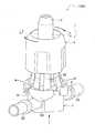
図1に示すように、コネクタ組立体1000は、オス型コネクタ1とメス型コネクタ2とを備える。
オス型コネクタ1は、コネクタ本体3と、ロック部材4と、係合部材5とを備える。それらの材質は、ある程度の柔軟性、耐久性等を有するものとして、例えば、ポリカーボネート、ポリアセタール、ポリプロピレン、ポリアクリルアミド、ポリエチレンテレフタレート等の合成樹脂であればよいが、それらに限定されない。As shown in FIG. 1, the
The
コネクタ本体3は、内部に流路を有しており、先端部31と、係合部材5の上面部51の孔部511で支持されるように少し窪んだ被支持部32と、を有している。 The
ロック部材4は、全体が略円筒形状で、使用時に係合部材5の外側に配置される部材である。ロック部材4は、開口部41、42と、係合部材5の複数のスリット部54それぞれにスライド可能に挿入される複数のリブ431(図2B(a)参照)を内側に有する凸部43と、複数の凸部43の間に位置する複数の凹部44と、を備える。 The
係合部材5は、全体が略円筒形状で、メス型コネクタ2と係合する部材である。係合部材5は、内挿されたコネクタ本体3の被支持部32を固定支持する孔部511(支持部)を有する上面部51と、上面部51に一端が固定されている爪支持部52と、メス型コネクタ2と係合する複数の爪部53と、複数の爪部53の間に設けられた複数のスリット部54と、スリット部54の開放方向の延長上に位置するストッパ55と、を備える。なお、爪部53は、内側に爪531を有している(図2B(a)(b)参照)。 The engaging
メス型コネクタ2は、本体部21と、ポート22、23と、弁体支持部24と、弁体241とを備える。
本体部21は、全体が略円筒形状で、オス型コネクタ1の係合部材5の複数の爪部53の爪531それぞれと係合するように、半径外側方向に突出している複数のフランジ部211を有する。また、複数のフランジ部211の間には、フランジ部211と比べて、軸方向全体にわたって半径外側方向に隆起している複数の非フランジ部212が設けられている。The
The
なお、オス型コネクタ1の係合部材5の複数の爪部53それぞれと、メス型コネクタ2の複数の非フランジ部212それぞれとは、オス型コネクタ1とメス型コネクタ2とが接続するときに対向する部分が山型の形状となっている。これにより、オス型コネクタ1とメス型コネクタ2との接続操作時に、円周方向の位置決めをしなくても、オス型コネクタ1の係合部材5の複数の爪部53それぞれが、メス型コネクタ2の本体部21の複数の非フランジ部212からフランジ部211の位置に誘導されるので、接続操作がより容易になる。 Each of the plurality of
ポート22、23は、医療用チューブを接続するための部材であり、内部に流路を有する。
弁体241は、オス型コネクタ1のコネクタ本体3と接続する部材であり、弁体支持部24、25によって支持される(図3B(a)参照)。The
The
次に、図1〜図2Bを参照して、オス型コネクタ1においてコネクタ本体3とロック部材4と係合部材5とを連結(接続)させる場合の動作について説明する。
まず、コネクタ本体3を先端部31側から係合部材5の上面部51の孔部511に上から挿入し、コネクタ本体3の被支持部32と係合部材5の上面部51の孔部511とを係合させる(図2B(a)(b)参照)。Next, with reference to FIGS. 1-2B, the operation | movement in the case of connecting the connector
First, the connector
次に、係合したコネクタ本体3と係合部材5を、ロック部材4に対して、下から、つまり開口部42側から挿入する。ストッパ55の外周面部分がテーパー状になっているので(図2B(a)参照)、ロック部材4のリブ431が係合部材5のストッパ55の横を通過する際に必要な力は小さくて済む。ロック部材4の底面と係合部材5が接したとき、ロック部材4と係合部材5は、それぞれ凸部45とリブ56が軽く当接することによって、軽く固定される(図2B(b)参照)。以下、図2Aに示す状態のオス型コネクタ1を「連結したオス型コネクタ1」と称する。 Next, the engaged connector
次に、図1〜図3Bを参照して、連結したオス型コネクタ1とメス型コネクタ2とを連結させる場合の動作について説明する。
連結したオス型コネクタ1とメス型コネクタ2とを、それぞれ、係合部材5の爪部53と、本体部21のフランジ部211および非フランジ部212とが対向するような相対位置の状態で、お互いに近づける。Next, with reference to FIGS. 1-3B, the operation | movement in the case of connecting the connected
The connected
そうすると、フランジ部211の上部がテーパー状になっているので、小さな力で、係合部材5の爪531が本体部21のフランジ部211の横を通過し、爪531がフランジ部211と係合し、連結したオス型コネクタ1とメス型コネクタ2とが連結し、それらはお互いに固定される(図3B(b)参照)。その際、コネクタ本体3は、メス型コネクタ2の弁体241に接続される。 Then, since the upper portion of the
なお、オス型コネクタ1の係合部材5の複数の爪部53それぞれと、メス型コネクタ2の複数の非フランジ部212それぞれとが、山型の形状となっていることで、オス型コネクタ1とメス型コネクタ2との接続操作時に、円周方向の位置決めをしなくても、オス型コネクタ1の係合部材5の複数の爪部53それぞれが、メス型コネクタ2の複数の非フランジ部212からフランジ部211の位置に誘導されるので、容易に接続操作を行うことができる。 Each of the plurality of
なお、以下、図3Aに示す状態のコネクタ組立体1000を「連結したコネクタ組立体1000」と称する。また、図3Aに示す連結したコネクタ組立体1000におけるC−C断面図は、図3B(a)に示す通りである。 Hereinafter, the
次に、図4A〜図5Cを参照して、連結したコネクタ組立体1000を、オス型コネクタ1とメス型コネクタ2に分離させる場合の動作について説明する。
まず、図4Aに示すように、ユーザは、ロック部材4を上方に移動させ、係合部材5から遠ざける。これにより、係合部材5の複数の爪部53は、ロック部材4による半径外側方向に対する移動の規制がなくなって、半径外側方向に開放可能となる(図4B(a)(b)参照)。ただし、この状態では、図4Cに示すように、係合部材5の爪部53の爪531がメス型コネクタ2の本体部21のフランジ部211と係合しているので、係合部材5はメス型コネクタ2から離脱しない。Next, with reference to FIG. 4A-FIG. 5C, operation | movement in the case of separating the
First, as shown in FIG. 4A, the user moves the
なお、ロック部材4と係合部材5は、凸部45とリブ56の当接によって軽く固定されているだけなので(図2B(b)参照)、ユーザは軽い力でそれらを遠ざけることができる。また、ロック部材4と係合部材5を遠ざけたとき、リブ431とストッパ55が当接することで(図4B(a)参照)、ユーザがよほど大きな力を加えない限り、ロック部材4が係合部材5から完全に離脱することはない。 Since the
次に、ユーザは、図5Aに示すように、係合部材5から遠ざけたロック部材4を時計回りに30度ほど回転させる。そうすると、ロック部材4のリブ431が係合部材5のスリット部54に挿入されているので、ロック部材4の回転に連動して、係合部材5も回転する。 Next, as shown in FIG. 5A, the user rotates the
これにより、係合部材5の複数の爪部53の爪531は、それぞれ、本体部21の複数の非フランジ部212に乗り上げ(図5B、図5C参照)、フランジ部211との係合状態から解放される。したがって、オス型コネクタ1がメス型コネクタ2から離脱可能となり、ユーザは、この状態からオス型コネクタ1とメス型コネクタ2とを互いに遠ざける方向に動かせば、オス型コネクタ1とメス型コネクタ2を分離させることができる。 Accordingly, the
このように、本実施形態のコネクタ組立体1000によれば、オス型コネクタ1とメス型コネクタ2との接続操作を一動作とし、それらの離脱操作を二動作とすることができる。
つまり、それらの接続操作では、お互いを押し込むことで、オス型コネクタ1のコネクタ本体3をメス型コネクタ2の弁体241に接続しつつ、オス型コネクタ1の係合部材5の複数の爪部53(の爪531)それぞれを、メス型コネクタ2の本体部21の複数のフランジ部211それぞれに係合させることで、オス型コネクタ1とメス型コネクタ2とを安定的に固定させることができる。また、このような固定により、通常のネジのように、固定が徐々に緩んだり、もしくは、そのような緩みを防止するために固く締め付けすぎて緩めることが困難になったり、といった事態を回避できる。Thus, according to the
That is, in these connection operations, the plurality of claws of the engaging
また、それらの離脱操作では、オス型コネクタ1のロック部材4を係合部材5から遠ざけるという1つ目の動作と、ロック部材4を回転させるという2つ目の動作とによって初めて、オス型コネクタ1の係合部材5の複数の爪部53(の爪531)それぞれがメス型コネクタ2の本体部21の複数のフランジ部211それぞれから複数の非フランジ部212それぞれに移動し、オス型コネクタ1とメス型コネクタ2との離脱が可能になる。 Moreover, in those detachment operations, the
したがって、コネクタ同士の接続を容易にするとともに、意図しない場面でのコネクタ同士の離脱の可能性を低減することができる。つまり、図3Aに示す状態で、ロック部材4を回転させようとしても、係合部材5の複数の爪部53とつながっている爪支持部52がロック部材4による半径外側方向に対する移動の規制を受けているので、爪部53は半径外側方向に開放できない。そして、メス型コネクタ2の本体部21の非フランジ部212が半径外側方向に隆起していることから、係合部材5は回転できない。したがって、スリット部54とリブ431によって係合部材5と回転方向に係合しているロック部材4も回転できない。 Therefore, it is possible to facilitate the connection between the connectors and reduce the possibility of the connectors being detached in an unintended scene. That is, even if the
また、オス型コネクタ1の係合部材5の複数の爪部53それぞれと、メス型コネクタ2の複数の非フランジ部212それぞれとが、山型の形状となっていることで、オス型コネクタ1とメス型コネクタ2との接続操作時に、円周方向の位置決めをしなくても、オス型コネクタ1の係合部材5の複数の爪部53それぞれが、メス型コネクタ2の複数の非フランジ部212からフランジ部211の位置に誘導されるので、接続操作がより容易になる。 In addition, each of the plurality of
また、オス型コネクタ1の係合部材5の爪部53(の爪531)や、メス型コネクタ2のフランジ部211が複数であることで、それらが単一の場合に比べて、オス型コネクタ1とメス型コネクタ2との接続状態のときに、接続部分が互いに近づき、それ以外の部分が遠ざかるような部材の変形(反り返り)の可能性や度合いを低減することができる。 Moreover, since there are a plurality of claws 53 (the claws 531) of the engaging
なお、図2B(a)(b)に示すように、オス型コネクタ1は、係合部材5の爪支持部52の内面にネジ溝が形成されている。これにより、オス型コネクタ1は、公知の一般的な形状でネジ山を有するメス型コネクタに対して、コネクタ本体3がルアー嵌合するとともに、係合部材5が螺合することが可能となっている。 In addition, as shown to FIG. 2B (a) (b), as for the
また、図1に示すように、メス型コネクタ2は、弁体支持部24の外面にネジ山が形成されている。これにより、メス型コネクタ2に対して、公知の一般的な形状でネジ溝を有するオス型コネクタを、弁体241に挿入するとともに、弁体支持部24に螺合させることが可能となっている。 Further, as shown in FIG. 1, the
以上で本実施形態の説明を終えるが、本発明の態様はこれらに限定されるものではない。
例えば、係合部材5における爪部53やスリット部54の数を「4」としたが、「6」などのそれ以外の数であってもよい。
その他、各部や各手段の具体的な構成について、本発明の主旨を逸脱しない範囲で適宜変更が可能である。Although description of this embodiment is finished above, the aspect of the present invention is not limited to these.
For example, although the number of the
In addition, the specific configuration of each unit and each means can be appropriately changed without departing from the gist of the present invention.
1 オス型コネクタ
2 メス型コネクタ
3 コネクタ本体
4 ロック部材
5 係合部材
21 本体部
22、23 ポート
24 弁体支持部
31 先端部
32 被支持部
41、42 開口部
43 凸部
44 凹部
45 凸部
51 上面部
52 爪支持部
53 爪部
54 スリット部
55 ストッパ
56 リブ
211 フランジ部
212 非フランジ部
241 弁体
431 リブ
511 孔部
531 爪
1000 コネクタ組立体DESCRIPTION OF
Claims (5)
Translated fromJapanese前記オス型コネクタは、
コネクタ本体と、
前記コネクタ本体を内部に固定支持する支持部、
前記メス型コネクタと係合する複数の爪部、および、
前記複数の爪部の間に設けられた複数のスリット部を有する係合部材と、
前記係合部材の外側に配置され、前記係合部材と回転方向に係合するロック部材と、を備えており、
前記メス型コネクタは、
前記オス型コネクタの係合部材の複数の爪部それぞれと係合するように、半径外側方向に突出している複数のフランジ部、および、
前記複数のフランジ部の間に設けられている複数の非フランジ部を有する本体部を備えており、
前記オス型コネクタと前記メス型コネクタとは、それぞれ、
前記オス型コネクタが前記メス型コネクタに接続される際に、前記オス型コネクタのコネクタ本体が前記メス型コネクタに接続されるとともに、前記オス型コネクタの係合部材の複数の爪部それぞれが前記メス型コネクタの本体部の複数のフランジ部それぞれに係合することで前記オス型コネクタが前記メス型コネクタに固定される構成となり、
前記係合部材の複数の爪部が前記ロック部材による半径外側方向に対する移動の規制を受けている状態で、前記係合部材および前記ロック部材が前記メス型コネクタに対して円周方向に回転することを規制し、前記オス型コネクタの係合部材の複数の爪部それぞれが前記メス型コネクタの本体部の複数のフランジ部それぞれから複数の非フランジ部それぞれに移動することを規制することで、前記オス型コネクタが前記メス型コネクタから離脱することを阻止する構成となっている
ことを特徴とするコネクタ組立体。A connector assembly comprising a male connector and a female connector connected to each other,
The male connector is
A connector body;
A support portion for fixing and supporting the connector body inside;
A plurality of claws engaging with the female connector; and
An engaging member having a plurality of slit portions provided between the plurality of claw portions;
A locking member that is disposed outside the engaging member and engages with the engaging member in a rotational direction;
The female connector is
A plurality of flange portions projecting radially outward so as to engage with the plurality of claw portions of the engaging member of the male connector, and
A main body having a plurality of non-flange portions provided between the plurality of flange portions;
The male connector and the female connector are respectively
When the male connector is connected to the female connector, the connector body of the male connector is connected to the female connector, and each of the plurality of claws of the engaging member of the male connector is connected to the female connector. The male connector is configured to be fixed to the female connector by engaging with each of the plurality of flange portions of the main body of the female connector,
The engagement member and the lock member rotate in the circumferential direction with respect to the female connector in a state where the plurality of claw portions of the engagement member are restricted from moving in the radially outward direction by the lock member. By restricting that, each of the plurality of claw portions of the engaging member of the male connector is restricted from moving from each of the plurality of flange portions of the main body portion of the female connector to each of the plurality of non-flange portions, The connector assembly is configured to prevent the male connector from being detached from the female connector.
前記複数のフランジ部の間に設けられている複数の非フランジ部を有する本体部を備えるメス型コネクタと接続するオス型コネクタであって、
コネクタ本体と、
前記コネクタ本体を内部に固定支持する支持部、
前記メス型コネクタと係合する複数の爪部、および、
前記複数の爪部の間に設けられた複数のスリット部を有する係合部材と、
前記係合部材の外側に配置され、前記係合部材と回転方向に係合するロック部材と、を備えており、
前記メス型コネクタに接続される際に、前記コネクタ本体が前記メス型コネクタに接続されるとともに、前記係合部材の複数の爪部それぞれが前記メス型コネクタの本体部の複数のフランジ部それぞれに係合することで、前記メス型コネクタに固定される構成となり、
前記係合部材の複数の爪部が前記ロック部材による半径外側方向に対する移動の規制を受けている状態で、前記係合部材および前記ロック部材が前記メス型コネクタに対して円周方向に回転することが規制され、前記係合部材の複数の爪部それぞれが前記メス型コネクタの本体部の複数のフランジ部それぞれから複数の非フランジ部それぞれに移動することが規制されることで、前記メス型コネクタから離脱することが阻止される構成となっている
ことを特徴とするオス型コネクタ。A plurality of flange portions projecting radially outward, and
A male connector connected to a female connector including a main body portion having a plurality of non-flange portions provided between the plurality of flange portions,
A connector body;
A support portion for fixing and supporting the connector body inside;
A plurality of claws engaging with the female connector; and
An engaging member having a plurality of slit portions provided between the plurality of claw portions;
A locking member that is disposed outside the engaging member and engages with the engaging member in a rotational direction;
When connected to the female connector, the connector body is connected to the female connector, and the plurality of claw portions of the engaging member are respectively connected to the plurality of flange portions of the female connector body portion. By engaging, it is configured to be fixed to the female connector,
The engagement member and the lock member rotate in the circumferential direction with respect to the female connector in a state where the plurality of claw portions of the engagement member are restricted from moving in the radially outward direction by the lock member. The plurality of claw portions of the engaging member are restricted from moving from the plurality of flange portions of the female connector main body portion to the plurality of non-flange portions, respectively. A male connector characterized in that it is configured to be prevented from being detached from the connector.
前記オス型コネクタの係合部材の複数の爪部それぞれを前記メス型コネクタの本体部の複数のフランジ部それぞれに係合することで、前記オス型コネクタを前記メス型コネクタに固定するステップと、を含み、
前記オス型コネクタを前記メス型コネクタに固定するステップにおいて、前記係合部材および前記ロック部材が前記メス型コネクタに対して円周方向に回転することが規制されることを特徴とする前記オス型コネクタと前記メス型コネクタとを互いに接続したコネクタ組立体を組み立てる組立方法。An engagement member having a connector main body, a support portion for fixing and supporting the connector main body therein, a plurality of claw portions, and a plurality of slit portions provided between the plurality of claw portions; A male connector comprising a locking member disposed on the outer side and engaged with the engaging member in a rotational direction, and radially outward so as to engage with each of the plurality of claws of the engaging member of the male connector. Preparing a female connector including a plurality of flange portions projecting in a direction and a main body portion having a plurality of non-flange portions provided between the plurality of flange portions;
Fixing the male connector to the female connector by engaging each of the plurality of claws of the engaging member of the male connector with each of the plurality of flanges of the main body of the female connector; Including
In the step of fixing the male connector to the female connector, the engagement member and the lock member are restricted from rotating in a circumferential direction with respect to the female connector. An assembly method for assembling a connector assembly in which a connector and the female connector are connected to each other.
前記オス型コネクタの係合部材の複数の爪部それぞれを前記メス型コネクタの本体部の複数のフランジ部それぞれに係合することで、前記オス型コネクタを前記メス型コネクタに固定するステップと、を含み、
前記オス型コネクタを前記メス型コネクタに固定するステップにおいて、前記係合部材の複数の爪部それぞれが前記メス型コネクタの本体部の複数のフランジ部それぞれから複数の非フランジ部それぞれに移動することが規制されることで、前記オス型コネクタが前記メス型コネクタから離脱することが阻止されることを特徴とする前記オス型コネクタと前記メス型コネクタとを互いに接続したコネクタ組立体を組み立てる組立方法。An engagement member having a connector main body, a support portion for fixing and supporting the connector main body therein, a plurality of claw portions, and a plurality of slit portions provided between the plurality of claw portions; A male connector comprising a locking member disposed on the outer side and engaged with the engaging member in a rotational direction, and radially outward so as to engage with each of the plurality of claws of the engaging member of the male connector. Preparing a female connector including a plurality of flange portions projecting in a direction and a main body portion having a plurality of non-flange portions provided between the plurality of flange portions;
Fixing the male connector to the female connector by engaging each of the plurality of claws of the engaging member of the male connector with each of the plurality of flanges of the main body of the female connector; Including
In the step of fixing the male connector to the female connector, each of the plurality of claw portions of the engaging member moves from each of the plurality of flange portions of the main body portion of the female connector to each of a plurality of non-flange portions. The assembly method for assembling the connector assembly in which the male connector and the female connector are connected to each other is prevented from being separated from the female connector by restricting the male connector. .
Applications Claiming Priority (2)
| Application Number | Priority Date | Filing Date | Title |
|---|---|---|---|
| JP2011066069 | 2011-03-24 | ||
| JP2011066069 | 2011-03-24 |
Related Parent Applications (1)
| Application Number | Title | Priority Date | Filing Date |
|---|---|---|---|
| JP2013506002ADivisionJP5956427B2 (en) | 2011-03-24 | 2012-03-22 | Connector assembly, male connector, female connector, and separation method |
Publications (2)
| Publication Number | Publication Date |
|---|---|
| JP2016163811Atrue JP2016163811A (en) | 2016-09-08 |
| JP6272952B2 JP6272952B2 (en) | 2018-01-31 |
Family
ID=46879462
Family Applications (2)
| Application Number | Title | Priority Date | Filing Date |
|---|---|---|---|
| JP2013506002AActiveJP5956427B2 (en) | 2011-03-24 | 2012-03-22 | Connector assembly, male connector, female connector, and separation method |
| JP2016119415AActiveJP6272952B2 (en) | 2011-03-24 | 2016-06-15 | Connector assembly, male connector, and assembly method |
Family Applications Before (1)
| Application Number | Title | Priority Date | Filing Date |
|---|---|---|---|
| JP2013506002AActiveJP5956427B2 (en) | 2011-03-24 | 2012-03-22 | Connector assembly, male connector, female connector, and separation method |
Country Status (6)
| Country | Link |
|---|---|
| US (1) | US9884177B2 (en) |
| EP (1) | EP2689798B1 (en) |
| JP (2) | JP5956427B2 (en) |
| CN (1) | CN103458957B (en) |
| AU (2) | AU2012232123B2 (en) |
| WO (1) | WO2012128321A1 (en) |
Families Citing this family (21)
| Publication number | Priority date | Publication date | Assignee | Title |
|---|---|---|---|---|
| CN104640599B (en)* | 2012-09-28 | 2017-05-24 | 泰尔茂株式会社 | Connector |
| EP2943712B1 (en)* | 2013-01-14 | 2017-03-08 | Zodiac Aerosafety Systems | Lever quick connect intercom fitting |
| JP2015051092A (en)* | 2013-09-06 | 2015-03-19 | 株式会社ジェイ・エム・エス | Double male connector |
| JP6318531B2 (en)* | 2013-10-08 | 2018-05-09 | 株式会社ジェイ・エム・エス | Male connector, female connector, and connector set |
| US10596068B2 (en) | 2014-05-02 | 2020-03-24 | Jms Co., Ltd. | Drug container connector and male member cover |
| JP6582412B2 (en)* | 2014-05-02 | 2019-10-02 | 株式会社ジェイ・エム・エス | connector |
| JP6707075B2 (en)* | 2015-03-11 | 2020-06-10 | テルモ株式会社 | Connector and medical device set |
| WO2016152137A1 (en) | 2015-03-20 | 2016-09-29 | テルモ株式会社 | Medical connector |
| WO2016152169A1 (en) | 2015-03-26 | 2016-09-29 | テルモ株式会社 | Medical connector |
| US10953215B2 (en) | 2015-04-08 | 2021-03-23 | Dale Medical Products, Inc. | Non-luer compatible administration port |
| US11052235B2 (en)* | 2015-05-18 | 2021-07-06 | Jms Co., Ltd. | Lever lock-type male connector and male connector assembly |
| US10039913B2 (en) | 2015-07-30 | 2018-08-07 | Carefusion 303, Inc. | Tamper-resistant cap |
| GB2541228B (en)* | 2015-08-13 | 2020-07-15 | Gm Global Tech Operations Llc | Quick fit connector |
| WO2017056477A1 (en)* | 2015-09-29 | 2017-04-06 | テルモ株式会社 | Connector, infusion set, and medical device capable of connecting to connector |
| JP6185534B2 (en)* | 2015-10-09 | 2017-08-23 | 日東工器株式会社 | Releasable connection structure and medical device having releasable connection structure |
| IT201600075597A1 (en)* | 2016-07-19 | 2018-01-19 | Borla Ind | FLOW COMPONENT PARTICULARLY FOR MEDICAL LINES FOR HEMODIALYSIS |
| WO2018081341A1 (en)* | 2016-10-26 | 2018-05-03 | Heartware, Inc. | Grooved connector with land bridge |
| CN110545858B (en)* | 2016-10-28 | 2023-06-20 | 医研比赫国际股份公司 | Catheter, coupling part for coupling catheter to tube, device including rectal catheter, and method of manufacturing catheter |
| US10898697B2 (en)* | 2017-10-05 | 2021-01-26 | Kirn Medical Design, Llc | Male insert for draining fluid from a patient |
| MX2022002830A (en)* | 2019-09-30 | 2022-04-06 | Oetiker Ny Inc | Radio-frequency identification connector. |
| US20240165343A1 (en)* | 2022-11-22 | 2024-05-23 | Becton, Dickinson And Company | Protective Cap for Preventing Contamination of a Needle-Free Connector |
Citations (6)
| Publication number | Priority date | Publication date | Assignee | Title |
|---|---|---|---|---|
| JPS50115823U (en)* | 1974-03-06 | 1975-09-20 | ||
| US4895570A (en)* | 1987-06-05 | 1990-01-23 | Abbott Laboratories | Locking port shroud for peritoneal dialysis tubing connector |
| JPH08243171A (en)* | 1995-03-10 | 1996-09-24 | Terumo Corp | Connector for medical treatment, bag for infusion having connector for medical treatment and appliance for medical treatment having connector for medical treatment |
| JP2002126094A (en)* | 2000-10-24 | 2002-05-08 | Terumo Corp | Connector system |
| JP2005536243A (en)* | 2002-06-24 | 2005-12-02 | ベルリン ハート アーゲー | Cannula tube coupling device made of flexible material |
| WO2006036192A1 (en)* | 2004-09-27 | 2006-04-06 | Medtronic, Inc. | Catheter connection systems and methods |
Family Cites Families (16)
| Publication number | Priority date | Publication date | Assignee | Title |
|---|---|---|---|---|
| US2877027A (en)* | 1956-04-30 | 1959-03-10 | Johnston Testers Inc | High pressure hose coupling with pressure-wedged sealing means |
| US6077259A (en) | 1998-09-30 | 2000-06-20 | Becton, Dickinson And Company | Contamination resistant connector |
| US7004934B2 (en)* | 2001-09-06 | 2006-02-28 | Vaillancourt Vincent L | Closed system connector assembly |
| US6880587B1 (en)* | 2002-02-23 | 2005-04-19 | Precision Thermoplastic Components, Inc. | Refrigerant material transfer device and method |
| US20050082828A1 (en)* | 2003-09-12 | 2005-04-21 | Wicks Jeffrey C. | Releasable connection assembly for joining tubing sections |
| WO2005030316A1 (en) | 2003-09-26 | 2005-04-07 | Medtronic, Inc. | Sutureless pump connector |
| US7497484B2 (en)* | 2004-08-11 | 2009-03-03 | Smiths Medical Asd, Inc. | Medical coupling system |
| US8211089B2 (en)* | 2006-03-24 | 2012-07-03 | Nexus Medical, Llc | Intravenous injection site with split septum and pressure activated flow control valve |
| US8257286B2 (en)* | 2006-09-21 | 2012-09-04 | Tyco Healthcare Group Lp | Safety connector apparatus |
| ITMO20070240A1 (en)* | 2007-07-19 | 2009-01-20 | Aries S R L | PERFECT CLOSING DEVICE FOR ADMINISTRATION LINES OF MEDICAL OR PHARMACEUTICAL FLUIDS FROM CONTAINERS AND SIMILAR |
| GB2451891A (en)* | 2007-08-17 | 2009-02-18 | Univ Sheffield Hallam | Medical fluid connector with features to ensure correct coupling |
| US7543858B1 (en)* | 2008-02-18 | 2009-06-09 | Hudson Wang | Water pipe connector |
| EP2298406B1 (en)* | 2008-05-02 | 2014-07-02 | Terumo Kabushiki Kaisha | Connector assembly |
| US8181997B2 (en)* | 2009-05-22 | 2012-05-22 | Hsin-Fa Wang | Water hose connector |
| US8777932B2 (en)* | 2010-04-29 | 2014-07-15 | Medtronic, Inc. | Catheter connectors and systems, and methods of using same |
| US9376789B2 (en)* | 2011-03-08 | 2016-06-28 | As Ip Holdco, Llc | Quick connection coupling |
- 2012
- 2012-03-22JPJP2013506002Apatent/JP5956427B2/enactiveActive
- 2012-03-22CNCN201280014935.4Apatent/CN103458957B/enactiveActive
- 2012-03-22EPEP12761074.9Apatent/EP2689798B1/enactiveActive
- 2012-03-22AUAU2012232123Apatent/AU2012232123B2/enactiveActive
- 2012-03-22WOPCT/JP2012/057345patent/WO2012128321A1/enactiveApplication Filing
- 2013
- 2013-09-23USUS14/033,728patent/US9884177B2/enactiveActive
- 2016
- 2016-06-15JPJP2016119415Apatent/JP6272952B2/enactiveActive
- 2016-07-19AUAU2016206252Apatent/AU2016206252B2/enactiveActive
Patent Citations (6)
| Publication number | Priority date | Publication date | Assignee | Title |
|---|---|---|---|---|
| JPS50115823U (en)* | 1974-03-06 | 1975-09-20 | ||
| US4895570A (en)* | 1987-06-05 | 1990-01-23 | Abbott Laboratories | Locking port shroud for peritoneal dialysis tubing connector |
| JPH08243171A (en)* | 1995-03-10 | 1996-09-24 | Terumo Corp | Connector for medical treatment, bag for infusion having connector for medical treatment and appliance for medical treatment having connector for medical treatment |
| JP2002126094A (en)* | 2000-10-24 | 2002-05-08 | Terumo Corp | Connector system |
| JP2005536243A (en)* | 2002-06-24 | 2005-12-02 | ベルリン ハート アーゲー | Cannula tube coupling device made of flexible material |
| WO2006036192A1 (en)* | 2004-09-27 | 2006-04-06 | Medtronic, Inc. | Catheter connection systems and methods |
Also Published As
| Publication number | Publication date |
|---|---|
| JPWO2012128321A1 (en) | 2014-07-24 |
| EP2689798A1 (en) | 2014-01-29 |
| WO2012128321A1 (en) | 2012-09-27 |
| AU2012232123B2 (en) | 2016-04-21 |
| AU2016206252A1 (en) | 2016-08-04 |
| US9884177B2 (en) | 2018-02-06 |
| US20140021714A1 (en) | 2014-01-23 |
| EP2689798A4 (en) | 2014-08-06 |
| CN103458957B (en) | 2016-01-06 |
| AU2016206252B2 (en) | 2017-12-21 |
| AU2012232123A1 (en) | 2013-10-17 |
| JP6272952B2 (en) | 2018-01-31 |
| CN103458957A (en) | 2013-12-18 |
| EP2689798B1 (en) | 2015-10-28 |
| JP5956427B2 (en) | 2016-07-27 |
Similar Documents
| Publication | Publication Date | Title |
|---|---|---|
| JP6272952B2 (en) | Connector assembly, male connector, and assembly method | |
| CN102727966B (en) | The safety needle assembly connected with correct medication | |
| EP3260161B1 (en) | Lever lock male connector and male connector assembly | |
| CN103453256B (en) | Twist-lock connector with strengthening wing clamping part and reverse snap component | |
| CN107405479B (en) | Medical plugs and locking connectors that establish fluid communication between two systems | |
| US11052235B2 (en) | Lever lock-type male connector and male connector assembly | |
| US11738189B2 (en) | Medical connector | |
| US10716929B2 (en) | Connector and medical device set | |
| US10500390B2 (en) | Medical connector | |
| US10881848B2 (en) | Connector, infusion set, and medical device connectable to connector | |
| HK1191274A (en) | Connecter assembly, male connecter, and female connecter | |
| JP7445745B2 (en) | Connector set and female connector | |
| JP2005296141A (en) | Syringe with connector and connector | |
| JP2021045419A (en) | Medical connector |
Legal Events
| Date | Code | Title | Description |
|---|---|---|---|
| A621 | Written request for application examination | Free format text:JAPANESE INTERMEDIATE CODE: A621 Effective date:20160615 | |
| RD02 | Notification of acceptance of power of attorney | Free format text:JAPANESE INTERMEDIATE CODE: A7422 Effective date:20160725 | |
| A131 | Notification of reasons for refusal | Free format text:JAPANESE INTERMEDIATE CODE: A131 Effective date:20170509 | |
| A521 | Request for written amendment filed | Free format text:JAPANESE INTERMEDIATE CODE: A523 Effective date:20170707 | |
| TRDD | Decision of grant or rejection written | ||
| A01 | Written decision to grant a patent or to grant a registration (utility model) | Free format text:JAPANESE INTERMEDIATE CODE: A01 Effective date:20171205 | |
| A61 | First payment of annual fees (during grant procedure) | Free format text:JAPANESE INTERMEDIATE CODE: A61 Effective date:20180104 | |
| R150 | Certificate of patent or registration of utility model | Ref document number:6272952 Country of ref document:JP Free format text:JAPANESE INTERMEDIATE CODE: R150 | |
| R250 | Receipt of annual fees | Free format text:JAPANESE INTERMEDIATE CODE: R250 | |
| R250 | Receipt of annual fees | Free format text:JAPANESE INTERMEDIATE CODE: R250 | |
| R250 | Receipt of annual fees | Free format text:JAPANESE INTERMEDIATE CODE: R250 | |
| R250 | Receipt of annual fees | Free format text:JAPANESE INTERMEDIATE CODE: R250 | |
| R250 | Receipt of annual fees | Free format text:JAPANESE INTERMEDIATE CODE: R250 |