JP2016162249A - Sensor management device, sensor, monitoring system, sensor management method, sensor management program, monitoring method, and monitoring program - Google Patents
Sensor management device, sensor, monitoring system, sensor management method, sensor management program, monitoring method, and monitoring programDownload PDFInfo
- Publication number
- JP2016162249A JP2016162249AJP2015040824AJP2015040824AJP2016162249AJP 2016162249 AJP2016162249 AJP 2016162249AJP 2015040824 AJP2015040824 AJP 2015040824AJP 2015040824 AJP2015040824 AJP 2015040824AJP 2016162249 AJP2016162249 AJP 2016162249A
- Authority
- JP
- Japan
- Prior art keywords
- sensor
- display
- information
- screen
- measurement result
- Prior art date
- Legal status (The legal status is an assumption and is not a legal conclusion. Google has not performed a legal analysis and makes no representation as to the accuracy of the status listed.)
- Pending
Links
Images


Classifications
- H—ELECTRICITY
- H04—ELECTRIC COMMUNICATION TECHNIQUE
- H04Q—SELECTING
- H04Q9/00—Arrangements in telecontrol or telemetry systems for selectively calling a substation from a main station, in which substation desired apparatus is selected for applying a control signal thereto or for obtaining measured values therefrom
- G—PHYSICS
- G06—COMPUTING OR CALCULATING; COUNTING
- G06T—IMAGE DATA PROCESSING OR GENERATION, IN GENERAL
- G06T11/00—2D [Two Dimensional] image generation
- G06T11/20—Drawing from basic elements, e.g. lines or circles
- G06T11/206—Drawing of charts or graphs
- H—ELECTRICITY
- H04—ELECTRIC COMMUNICATION TECHNIQUE
- H04Q—SELECTING
- H04Q2209/00—Arrangements in telecontrol or telemetry systems
- H04Q2209/80—Arrangements in the sub-station, i.e. sensing device
- H04Q2209/86—Performing a diagnostic of the sensing device
- H—ELECTRICITY
- H04—ELECTRIC COMMUNICATION TECHNIQUE
- H04Q—SELECTING
- H04Q2209/00—Arrangements in telecontrol or telemetry systems
- H04Q2209/80—Arrangements in the sub-station, i.e. sensing device
- H04Q2209/88—Providing power supply at the sub-station
Landscapes
- Engineering & Computer Science (AREA)
- Computer Networks & Wireless Communication (AREA)
- Physics & Mathematics (AREA)
- General Physics & Mathematics (AREA)
- Theoretical Computer Science (AREA)
- Arrangements For Transmission Of Measured Signals (AREA)
- Testing And Monitoring For Control Systems (AREA)
Abstract
Description
Translated fromJapanese本発明は、センサ管理装置、センサ、監視システム、センサ管理方法、センサ管理プログラム、監視方法および監視プログラムに関し、特に、センサによる計測結果を画面に表示する制御を行うセンサ管理装置、センサ、監視システム、センサ管理方法、センサ管理プログラム、監視方法および監視プログラムに関する。 The present invention relates to a sensor management device, a sensor, a monitoring system, a sensor management method, a sensor management program, a monitoring method, and a monitoring program, and in particular, a sensor management device, a sensor, and a monitoring system that perform control to display a measurement result by a sensor on a screen. , A sensor management method, a sensor management program, a monitoring method, and a monitoring program.
所定エリアの状態をモニタするための技術が各種開発されている。たとえば、特許第5456414号公報(特許文献1)には、以下のような技術が開示されている。すなわち、エリア監視用の表示方法は、監視対象エリア内の各所に配した複数のセンサで、少なくとも一種類の所要の事象に関する値あるいはその変化値を測定し、該測定で得たデータを処理して処理結果をモニタ画面上に表示するエリア監視用の表示方法であって、前記監視対象エリアを示すエリア表示に、前記処理結果の表示を重ねて表示するとともに、前記モニタ画面での前記エリア表示上における前記処理結果の表示位置を、該処理結果を得た前記センサの配置箇所に対応あるいはほぼ対応する位置としてなるエリア監視用の表示方法において、前記処理結果の表示形態に円形々状を用い、該表示する円形々状は、その中心が測定地点を表示し、その大きさが測定値の大きさ(絶対値)を表し、その色を半透明とし、前記処理結果の表示が、前記監視対象エリアの表示上での測定地点に重なり合って表示される視認可能な半透明なものとする。 Various techniques for monitoring the state of a predetermined area have been developed. For example, Japanese Patent No. 5456414 (Patent Document 1) discloses the following technique. In other words, the display method for area monitoring uses a plurality of sensors arranged at various locations in the monitored area to measure a value related to at least one type of required event or its change value and process the data obtained by the measurement. Display the processing result on the monitor screen, wherein the display of the processing result is superimposed on the area display indicating the monitored area, and the area display on the monitor screen is displayed. In the display method for area monitoring in which the display position of the processing result is a position corresponding to or substantially corresponding to the location of the sensor from which the processing result is obtained, a circular shape is used for the display form of the processing result. The circles to be displayed indicate the measurement point at the center, the magnitude represents the magnitude (absolute value) of the measurement value, the color is translucent, It indicates that, for said one monitored area display on the measurement point in semi viewable transparency is displayed overlapping in.
上記のような技術において、あるセンサからの計測結果が何らかの原因により表示側で取得できなくなる場合がある。 In the technique as described above, there are cases where the measurement result from a certain sensor cannot be acquired on the display side for some reason.
しかしながら、特許文献1には、このような問題点を解決するための構成は開示されていない。 However,
この発明は、上述の課題を解決するためになされたもので、その目的は、センサによる計測結果を画面に表示する構成において、センサの計測結果を表示側で取得できなくなった状況においてユーザを支援することが可能なセンサ管理装置、センサ、監視システム、センサ管理方法、センサ管理プログラム、監視方法および監視プログラムを提供することである。 The present invention has been made to solve the above-described problems, and its purpose is to support the user in a situation where the measurement result of the sensor cannot be obtained on the display side in the configuration in which the measurement result by the sensor is displayed on the screen. A sensor management device, a sensor, a monitoring system, a sensor management method, a sensor management program, a monitoring method, and a monitoring program are provided.
(1)上記課題を解決するために、この発明のある局面に係るセンサ管理装置は、センサによる計測結果を示すセンサ情報を受信する受信部と、前記受信部によって受信された前記センサ情報の示す前記計測結果と前記センサとを対応付けた画面を表示する制御を行う表示制御部とを備え、前記表示制御部は、前記センサ情報を前記受信部が受信できなくなった前記センサを認識可能となるように前記画面の表示内容を変更する制御を行う。 (1) In order to solve the above-described problem, a sensor management device according to an aspect of the present invention includes a receiving unit that receives sensor information indicating a measurement result by a sensor, and the sensor information received by the receiving unit. A display control unit that performs control to display a screen in which the measurement result and the sensor are associated with each other, and the display control unit can recognize the sensor in which the reception unit cannot receive the sensor information. In this way, control is performed to change the display content of the screen.
(10)上記課題を解決するために、この発明のある局面に係るセンサは、計測を行う計測部と、前記計測部による計測結果を示すセンサ情報を、前記センサ情報の示す前記計測結果と前記センサとを対応付けた画面を表示する制御を行うことが可能なセンサ管理装置へ送信する処理を行う送信処理部とを備え、前記送信処理部は、さらに、自己のセンサの電源がオフされた旨を示すオフ情報と自己のセンサの識別情報とを前記センサ管理装置へ送信する処理を行う。 (10) In order to solve the above-described problem, a sensor according to an aspect of the present invention includes a measurement unit that performs measurement, sensor information that indicates a measurement result by the measurement unit, and the measurement result indicated by the sensor information and the sensor information. A transmission processing unit that performs processing to transmit to a sensor management apparatus capable of performing control to display a screen in which the sensor is associated, and the transmission processing unit is further powered off by its own sensor A process of transmitting off information indicating the fact and identification information of its own sensor to the sensor management apparatus is performed.
(11)上記課題を解決するために、この発明のある局面に係る監視システムは、センサと、センサ管理装置とを備え、前記センサは、自己の計測結果を示すセンサ情報を前記センサ管理装置へ送信し、前記センサ管理装置は、前記センサから送信された前記センサ情報を受信し、受信した前記センサ情報の示す前記計測結果と前記センサとを対応付けた画面を表示する制御を行い、前記センサ管理装置は、前記センサ情報を自己が受信できなくなった前記センサを認識可能となるように前記画面の表示内容を変更する制御を行う。 (11) In order to solve the above-described problem, a monitoring system according to an aspect of the present invention includes a sensor and a sensor management device, and the sensor sends sensor information indicating its own measurement result to the sensor management device. The sensor management device receives the sensor information transmitted from the sensor, performs control to display a screen in which the measurement result indicated by the received sensor information is associated with the sensor, and the sensor The management device performs control to change the display content of the screen so that the sensor that can no longer receive the sensor information can be recognized.
(12)上記課題を解決するために、この発明のある局面に係るセンサ管理方法は、センサ管理装置におけるセンサ管理方法であって、センサによる計測結果を示すセンサ情報を受信するステップと、受信した前記センサ情報の示す前記計測結果と前記センサとを対応付けた画面を表示する制御を行うステップと、前記センサ情報を受信できなくなった前記センサを認識可能となるように前記画面の表示内容を変更する制御を行うステップとを含む。 (12) In order to solve the above-described problem, a sensor management method according to an aspect of the present invention is a sensor management method in a sensor management device, the step of receiving sensor information indicating a measurement result by a sensor, A step of performing a control to display a screen in which the measurement result indicated by the sensor information and the sensor are associated with each other, and changing the display content of the screen so that the sensor that can no longer receive the sensor information can be recognized. Performing the control to perform.
(13)上記課題を解決するために、この発明のある局面に係るセンサ管理プログラムは、センサ管理装置において用いられるセンサ管理プログラムであって、コンピュータに、センサによる計測結果を示すセンサ情報を受信するステップと、受信した前記センサ情報の示す前記計測結果と前記センサとを対応付けた画面を表示する制御を行うステップと、前記センサ情報を受信できなくなった前記センサを認識可能となるように前記画面の表示内容を変更する制御を行うステップとを実行させるためのプログラムである。 (13) In order to solve the above-described problem, a sensor management program according to an aspect of the present invention is a sensor management program used in a sensor management apparatus, and receives sensor information indicating a measurement result by a sensor in a computer. A step of performing a control to display a screen in which the measurement result indicated by the received sensor information and the sensor are associated with each other, and the screen so that the sensor that can no longer receive the sensor information can be recognized. Is a program for executing a step of performing control to change the display content of
(14)上記課題を解決するために、この発明のある局面に係る監視方法は、センサにおける監視方法であって、計測を行うステップと、計測結果を示すセンサ情報を、前記センサ情報の示す前記計測結果と前記センサとを対応付けた画面を表示する制御を行うことが可能なセンサ管理装置へ送信する処理を行うステップと、前記センサの電源がオフされた旨を示すオフ情報と前記センサの識別情報とを前記センサ管理装置へ送信するステップとを含む。 (14) In order to solve the above-described problem, a monitoring method according to an aspect of the present invention is a monitoring method in a sensor, and includes a step of performing measurement, and sensor information indicating a measurement result. Performing a process of transmitting to a sensor management apparatus capable of performing control to display a screen in which a measurement result and the sensor are associated with each other; off information indicating that the power of the sensor is turned off; Transmitting the identification information to the sensor management device.
(15)上記課題を解決するために、この発明のある局面に係る監視プログラムは、センサにおいて用いられる監視プログラムであって、コンピュータに、計測を行うステップと、計測結果を示すセンサ情報を、前記センサ情報の示す前記計測結果と前記センサとを対応付けた画面を表示する制御を行うことが可能なセンサ管理装置へ送信する処理を行うステップと、前記センサの電源がオフされた旨を示すオフ情報と前記センサの識別情報とを前記センサ管理装置へ送信するステップとを実行させるためのプログラムである。 (15) In order to solve the above-described problem, a monitoring program according to an aspect of the present invention is a monitoring program used in a sensor, and includes a step of performing measurement on a computer and sensor information indicating a measurement result. Performing a process of transmitting to a sensor management apparatus capable of performing control to display a screen in which the measurement result indicated by the sensor information and the sensor are associated with each other; and indicating that the power of the sensor is turned off. A program for executing a step of transmitting information and identification information of the sensor to the sensor management device.
本発明は、このような特徴的な処理部を備えるセンサ管理装置として実現することができるだけでなく、センサ管理装置の一部または全部を実現する半導体集積回路として実現することができる。 The present invention can be realized not only as a sensor management apparatus including such a characteristic processing unit, but also as a semiconductor integrated circuit that realizes part or all of the sensor management apparatus.
本発明によれば、センサによる計測結果を画面に表示する構成において、センサの計測結果を表示側で取得できなくなった状況においてユーザを支援することができる。 ADVANTAGE OF THE INVENTION According to this invention, in the structure which displays the measurement result by a sensor on a screen, a user can be supported in the condition where it became impossible to acquire the measurement result of a sensor on the display side.
最初に、本発明の実施の形態の内容を列記して説明する。 First, the contents of the embodiment of the present invention will be listed and described.
(1)本発明の実施の形態に係るセンサ管理装置は、センサによる計測結果を示すセンサ情報を受信する受信部と、前記受信部によって受信された前記センサ情報の示す前記計測結果と前記センサとを対応付けた画面を表示する制御を行う表示制御部とを備え、前記表示制御部は、前記センサ情報を前記受信部が受信できなくなった前記センサを認識可能となるように前記画面の表示内容を変更する制御を行う。 (1) A sensor management apparatus according to an embodiment of the present invention includes a receiving unit that receives sensor information indicating a measurement result by a sensor, the measurement result indicated by the sensor information received by the receiving unit, and the sensor. A display control unit that performs control to display a screen associated with each other, and the display control unit displays the content of the screen so that the sensor can no longer receive the sensor information. Control to change.
このような構成により、たとえば、センサ管理装置へのセンサ情報の伝送が停止したセンサと、当該伝送が継続しているセンサとをユーザが容易に識別することができる。また、たとえば、ユーザは、センサからのセンサ情報の伝送が停止した場合に、伝送が停止した原因の調査等、当該センサを復旧させるために必要な作業に速やかに取り掛かることができるため、当該センサによる計測結果を取得できない期間を短縮することができる。したがって、センサによる計測結果を画面に表示する構成において、センサの計測結果を表示側で取得できなくなった状況においてユーザを支援することができる。 With such a configuration, for example, the user can easily identify a sensor for which transmission of sensor information to the sensor management device has stopped and a sensor for which transmission has continued. In addition, for example, when the transmission of sensor information from a sensor is stopped, the user can quickly start work necessary to restore the sensor, such as investigating the cause of the stop of transmission. It is possible to shorten the period during which the measurement result cannot be obtained. Therefore, in the configuration in which the measurement result of the sensor is displayed on the screen, the user can be supported in a situation where the measurement result of the sensor cannot be acquired on the display side.
(2)好ましくは、前記表示制御部は、前記センサ情報を前記受信部が受信できなくなった前記センサと前記計測結果とを対応付けた内容を前記画面から削除する制御を行う。 (2) Preferably, the display control unit performs control to delete, from the screen, contents in which the sensor information that the receiving unit cannot receive is associated with the measurement result.
このような構成により、たとえば、センサ管理装置へのセンサ情報の伝送が継続しているセンサをユーザに認識させることができ、また、画面表示が煩雑になっている場合には、煩雑さを解消することができる。 With such a configuration, for example, it is possible to make the user recognize a sensor that continues to transmit sensor information to the sensor management device, and when the screen display is complicated, the complexity is eliminated. can do.
(3)好ましくは、前記表示制御部は、前記センサ情報を前記受信部が受信できなくなった原因をさらに示す前記画面を表示する制御を行う。 (3) Preferably, the said display control part performs control which displays the said screen which further shows the cause by which the said receiving part became unable to receive the said sensor information.
このような構成により、たとえば、ユーザは、センサからのセンサ情報の伝送が停止した原因を自ら調査することなく容易に把握することができるため、センサ情報の伝送の復旧を効率的に行うことができる。 With such a configuration, for example, the user can easily grasp the reason why the transmission of the sensor information from the sensor has stopped, without investigating himself / herself, so that the restoration of the transmission of the sensor information can be efficiently performed. it can.
(4)より好ましくは、前記受信部は、さらに、前記センサの電源がオフされた旨を示すオフ情報を前記センサから受信し、前記表示制御部は、前記受信部によって前記オフ情報が受信された場合、前記原因として、前記センサの電源がオフされた旨を示す前記画面を表示する制御を行う。 (4) More preferably, the receiving unit further receives off information indicating that the power of the sensor is turned off from the sensor, and the display control unit receives the off information by the receiving unit. If this happens, the control for displaying the screen indicating that the power source of the sensor is turned off is performed as the cause.
このような構成により、ユーザは、センサからのセンサ情報の伝送が停止した原因が、当該センサの電源がオフされたことであることを容易に把握することができる。 With such a configuration, the user can easily grasp that the cause of the stop of transmission of sensor information from the sensor is that the power of the sensor is turned off.
(5)より好ましくは、前記センサ管理装置は、さらに、前記センサと自己のセンサ管理装置との通信品質を判断する判断部を備え、前記表示制御部は、前記判断部によって前記通信品質が悪いと判断された場合、前記原因として前記通信品質が悪い旨を示す前記画面を表示する制御を行う。 (5) More preferably, the sensor management device further includes a determination unit that determines communication quality between the sensor and its own sensor management device, and the display control unit has a poor communication quality due to the determination unit. When it is determined that the communication quality is poor as the cause, control is performed to display the screen indicating that the communication quality is poor.
このような構成により、ユーザは、センサからのセンサ情報の伝送が停止した原因が、当該センサとセンサ管理装置との通信品質の悪化であることを容易に把握することができる。 With such a configuration, the user can easily grasp that the cause of the stop of transmission of sensor information from the sensor is a deterioration in communication quality between the sensor and the sensor management device.
(6)より好ましくは、前記受信部は、さらに、前記センサのバッテリの蓄電残量に関するバッテリ情報を前記センサから受信し、前記表示制御部は、前記蓄電残量が少ないことを示す前記バッテリ情報が前記受信部によって受信された場合、前記原因として前記蓄電残量が少ない旨を示す前記画面を表示する制御を行う。 (6) More preferably, the receiving unit further receives battery information related to a remaining amount of power stored in the battery of the sensor from the sensor, and the display control unit indicates that the remaining battery power is low. Is received by the receiving unit, the control is performed to display the screen indicating that the remaining power storage amount is low as the cause.
このような構成により、ユーザは、センサからのセンサ情報の伝送が停止した原因が、当該センサにおけるバッテリの蓄電残量の不足であることを容易に把握することができる。 With such a configuration, the user can easily grasp that the cause of the stop of the transmission of the sensor information from the sensor is the shortage of the remaining amount of the battery in the sensor.
(7)より好ましくは、前記表示制御部は、前記原因として前記センサが故障している旨を示すか、または前記原因の代わりに、前記原因が不明である旨を示す前記画面を表示する制御を行う。 (7) More preferably, the display control unit indicates that the sensor has failed as the cause, or displays the screen indicating that the cause is unknown instead of the cause. I do.
このような構成により、ユーザは、センサからのセンサ情報の伝送が停止した原因が、センサ管理装置によって判断可能な原因以外の原因であることを認識することができる。 With such a configuration, the user can recognize that the cause of the stop of transmission of sensor information from the sensor is a cause other than the cause that can be determined by the sensor management device.
(8)好ましくは、前記表示制御部は、前記センサ情報を前記受信部が受信できなくなった前記センサの識別情報のリストをさらに示す前記画面を表示する制御を行う。 (8) Preferably, the display control unit performs control to display the screen further indicating a list of identification information of the sensor that is no longer able to receive the sensor information.
このような構成により、ユーザは、センサ管理装置へのセンサ情報の伝送が停止したセンサの一覧を確認することができる。 With such a configuration, the user can check a list of sensors for which transmission of sensor information to the sensor management apparatus has stopped.
(9)好ましくは、前記表示制御部は、前記センサ情報を前記受信部が再び受信できるようになった前記センサに関する前記画面の表示内容を変更前に戻す制御を行う。 (9) Preferably, the display control unit performs control to return the display content of the screen related to the sensor, which is configured so that the receiving unit can receive the sensor information again, before the change.
このような構成により、たとえば、ユーザは、センサ管理装置へのセンサ情報の伝送が再開されたことを認識することができる。また、センサ管理装置においてセンサ情報を再び受信できるようになった場合に、画面の表示を自動で更新することができる。 With such a configuration, for example, the user can recognize that transmission of sensor information to the sensor management apparatus has been resumed. In addition, when the sensor information can be received again by the sensor management apparatus, the display on the screen can be automatically updated.
(10)本発明の実施の形態に係るセンサは、計測を行う計測部と、前記計測部による計測結果を示すセンサ情報を、前記センサ情報の示す前記計測結果と前記センサとを対応付けた画面を表示する制御を行うことが可能なセンサ管理装置へ送信する処理を行う送信処理部とを備え、前記送信処理部は、さらに、自己のセンサの電源がオフされた旨を示すオフ情報と自己のセンサの識別情報とを前記センサ管理装置へ送信する処理を行う。 (10) A sensor according to an embodiment of the present invention is a screen in which a measurement unit that performs measurement, sensor information that indicates a measurement result by the measurement unit, and a correspondence between the measurement result indicated by the sensor information and the sensor A transmission processing unit that performs processing to transmit to a sensor management device capable of performing control to display the information, and the transmission processing unit further includes off information indicating that the power of its sensor is turned off The sensor identification information is transmitted to the sensor management apparatus.
このような構成により、たとえば、ユーザは、センサからのセンサ情報の伝送が停止した場合に、当該伝送の停止の原因が、センサの電源がオフされたことであることを容易に把握することができる。したがって、センサによる計測結果を画面に表示する構成において、センサの計測結果を表示側で取得できなくなった状況においてユーザを支援することができる。 With such a configuration, for example, when transmission of sensor information from a sensor is stopped, the user can easily grasp that the cause of the stop of the transmission is that the power of the sensor is turned off. it can. Therefore, in the configuration in which the measurement result of the sensor is displayed on the screen, the user can be supported in a situation where the measurement result of the sensor cannot be acquired on the display side.
(11)本発明の実施の形態に係る監視システムは、センサと、センサ管理装置とを備え、前記センサは、自己の計測結果を示すセンサ情報を前記センサ管理装置へ送信し、前記センサ管理装置は、前記センサから送信された前記センサ情報を受信し、受信した前記センサ情報の示す前記計測結果と前記センサとを対応付けた画面を表示する制御を行い、前記センサ管理装置は、前記センサ情報を自己が受信できなくなった前記センサを認識可能となるように前記画面の表示内容を変更する制御を行う。 (11) A monitoring system according to an embodiment of the present invention includes a sensor and a sensor management device, and the sensor transmits sensor information indicating its own measurement result to the sensor management device, and the sensor management device. Receives the sensor information transmitted from the sensor, and performs control to display a screen in which the measurement result indicated by the received sensor information is associated with the sensor. The sensor management device Control is performed to change the display content of the screen so that the sensor can no longer receive the sensor.
このような構成により、たとえば、センサ管理装置へのセンサ情報の伝送が停止したセンサと、当該伝送が継続しているセンサとをユーザが容易に識別することができる。また、たとえば、ユーザは、センサからのセンサ情報の伝送が停止した場合に、伝送が停止した原因の調査等、当該センサを復旧させるために必要な作業に速やかに取り掛かることができるため、当該センサによる計測結果を取得できない期間を短縮することができる。したがって、センサによる計測結果を画面に表示する構成において、センサの計測結果を表示側で取得できなくなった状況においてユーザを支援することができる。 With such a configuration, for example, the user can easily identify a sensor for which transmission of sensor information to the sensor management device has stopped and a sensor for which transmission has continued. In addition, for example, when the transmission of sensor information from a sensor is stopped, the user can quickly start work necessary to restore the sensor, such as investigating the cause of the stop of transmission. It is possible to shorten the period during which the measurement result cannot be obtained. Therefore, in the configuration in which the measurement result of the sensor is displayed on the screen, the user can be supported in a situation where the measurement result of the sensor cannot be acquired on the display side.
(12)本発明の実施の形態に係るセンサ管理方法は、センサ管理装置におけるセンサ管理方法であって、センサによる計測結果を示すセンサ情報を受信するステップと、受信した前記センサ情報の示す前記計測結果と前記センサとを対応付けた画面を表示する制御を行うステップと、前記センサ情報を受信できなくなった前記センサを認識可能となるように前記画面の表示内容を変更する制御を行うステップとを含む。 (12) A sensor management method according to an embodiment of the present invention is a sensor management method in a sensor management apparatus, the step of receiving sensor information indicating a measurement result by a sensor, and the measurement indicated by the received sensor information. A step of performing control to display a screen in which a result and the sensor are associated with each other, and a step of performing control to change the display content of the screen so that the sensor that can no longer receive the sensor information can be recognized. Including.
このような構成により、たとえば、センサ管理装置へのセンサ情報の伝送が停止したセンサと、当該伝送が継続しているセンサとをユーザが容易に識別することができる。また、たとえば、ユーザは、センサからのセンサ情報の伝送が停止した場合に、伝送が停止した原因の調査等、当該センサを復旧させるために必要な作業に速やかに取り掛かることができるため、当該センサによる計測結果を取得できない期間を短縮することができる。したがって、センサによる計測結果を画面に表示する構成において、センサの計測結果を表示側で取得できなくなった状況においてユーザを支援することができる。 With such a configuration, for example, the user can easily identify a sensor for which transmission of sensor information to the sensor management device has stopped and a sensor for which transmission has continued. In addition, for example, when the transmission of sensor information from a sensor is stopped, the user can quickly start work necessary to restore the sensor, such as investigating the cause of the stop of transmission. It is possible to shorten the period during which the measurement result cannot be obtained. Therefore, in the configuration in which the measurement result of the sensor is displayed on the screen, the user can be supported in a situation where the measurement result of the sensor cannot be acquired on the display side.
(13)本発明の実施の形態に係るセンサ管理プログラムは、センサ管理装置において用いられるセンサ管理プログラムであって、コンピュータに、センサによる計測結果を示すセンサ情報を受信するステップと、受信した前記センサ情報の示す前記計測結果と前記センサとを対応付けた画面を表示する制御を行うステップと、前記センサ情報を受信できなくなった前記センサを認識可能となるように前記画面の表示内容を変更する制御を行うステップとを実行させるためのプログラムである。 (13) A sensor management program according to an embodiment of the present invention is a sensor management program used in a sensor management apparatus, the step of receiving sensor information indicating a measurement result by a sensor in a computer, and the received sensor Control for displaying a screen in which the measurement result indicated by the information and the sensor are associated with each other, and control for changing the display content of the screen so that the sensor that can no longer receive the sensor information can be recognized Is a program for executing the step of performing.
このような構成により、たとえば、センサ管理装置へのセンサ情報の伝送が停止したセンサと、当該伝送が継続しているセンサとをユーザが容易に識別することができる。また、たとえば、ユーザは、センサからのセンサ情報の伝送が停止した場合に、伝送が停止した原因の調査等、当該センサを復旧させるために必要な作業に速やかに取り掛かることができるため、当該センサによる計測結果を取得できない期間を短縮することができる。したがって、センサによる計測結果を画面に表示する構成において、センサの計測結果を表示側で取得できなくなった状況においてユーザを支援することができる。 With such a configuration, for example, the user can easily identify a sensor for which transmission of sensor information to the sensor management device has stopped and a sensor for which transmission has continued. In addition, for example, when the transmission of sensor information from a sensor is stopped, the user can quickly start work necessary to restore the sensor, such as investigating the cause of the stop of transmission. It is possible to shorten the period during which the measurement result cannot be obtained. Therefore, in the configuration in which the measurement result of the sensor is displayed on the screen, the user can be supported in a situation where the measurement result of the sensor cannot be acquired on the display side.
(14)本発明の実施の形態に係る監視方法は、センサにおける監視方法であって、計測を行うステップと、計測結果を示すセンサ情報を、前記センサ情報の示す前記計測結果と前記センサとを対応付けた画面を表示する制御を行うことが可能なセンサ管理装置へ送信する処理を行うステップと、前記センサの電源がオフされた旨を示すオフ情報と前記センサの識別情報とを前記センサ管理装置へ送信するステップとを含む。 (14) A monitoring method according to an embodiment of the present invention is a monitoring method in a sensor, and includes a step of performing measurement, sensor information indicating a measurement result, the measurement result indicated by the sensor information, and the sensor. A step of performing a process of transmitting to a sensor management apparatus capable of performing control to display the associated screen, off information indicating that the power of the sensor is turned off, and identification information of the sensor; Transmitting to the device.
このような構成により、たとえば、ユーザは、センサからのセンサ情報の伝送が停止した場合に、当該伝送の停止の原因が、センサの電源がオフされたことであることを容易に把握することができる。したがって、センサによる計測結果を画面に表示する構成において、センサの計測結果を表示側で取得できなくなった状況においてユーザを支援することができる。 With such a configuration, for example, when transmission of sensor information from a sensor is stopped, the user can easily grasp that the cause of the stop of the transmission is that the power of the sensor is turned off. it can. Therefore, in the configuration in which the measurement result of the sensor is displayed on the screen, the user can be supported in a situation where the measurement result of the sensor cannot be acquired on the display side.
(15)本発明の実施の形態に係る監視プログラムは、センサにおいて用いられる監視プログラムであって、コンピュータに、計測を行うステップと、計測結果を示すセンサ情報を、前記センサ情報の示す前記計測結果と前記センサとを対応付けた画面を表示する制御を行うことが可能なセンサ管理装置へ送信する処理を行うステップと、前記センサの電源がオフされた旨を示すオフ情報と前記センサの識別情報とを前記センサ管理装置へ送信するステップとを実行させるためのプログラムである。 (15) A monitoring program according to an embodiment of the present invention is a monitoring program used in a sensor, and includes a step of performing measurement on a computer, sensor information indicating a measurement result, and the measurement result indicated by the sensor information. And a step of performing a process of transmitting to a sensor management apparatus capable of performing control to display a screen in which the sensor is associated with each other, off information indicating that the power of the sensor is turned off, and identification information of the sensor Is transmitted to the sensor management apparatus.
このような構成により、たとえば、ユーザは、センサからのセンサ情報の伝送が停止した場合に、当該伝送の停止の原因が、センサの電源がオフされたことであることを容易に把握することができる。したがって、センサによる計測結果を画面に表示する構成において、センサの計測結果を表示側で取得できなくなった状況においてユーザを支援することができる。 With such a configuration, for example, when transmission of sensor information from a sensor is stopped, the user can easily grasp that the cause of the stop of the transmission is that the power of the sensor is turned off. it can. Therefore, in the configuration in which the measurement result of the sensor is displayed on the screen, the user can be supported in a situation where the measurement result of the sensor cannot be acquired on the display side.
以下、本発明の実施の形態について図面を用いて説明する。なお、図中同一または相当部分には同一符号を付してその説明は繰り返さない。また、以下に記載する実施形態の少なくとも一部を任意に組み合わせてもよい。 Hereinafter, embodiments of the present invention will be described with reference to the drawings. In the drawings, the same or corresponding parts are denoted by the same reference numerals and description thereof will not be repeated. Moreover, you may combine arbitrarily at least one part of embodiment described below.
[構成および基本動作]
図1は、本発明の実施の形態に係る監視システムの構成を示す図である。[Configuration and basic operation]
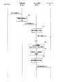
FIG. 1 is a diagram showing a configuration of a monitoring system according to an embodiment of the present invention.
図1を参照して、監視システム101は、複数のセンサ11と、センサ管理装置12と、ディスプレイ13と、無線通信装置14とを備える。なお、センサ管理装置12がディスプレイ13を含む構成であってもよい。 With reference to FIG. 1, the
センサ11は、バッテリ15を含み、バッテリ15から供給される電力によって動作する。センサ11は、工場または病院等の監視エリアにおいて設置され、監視対象に関する計測、たとえば、温度、湿度または電流等の計測を行う。 The
センサ11は、自己の識別情報すなわちID(Identification)と、計測結果を示す計測結果情報と、バッテリ15の蓄電残量に関するバッテリ情報とを含むセンサ情報を定期的または不定期に作成し、たとえば無線LAN(Local Area Network)またはZigBee(登録商標)等の通信方式に従って、作成したセンサ情報を無線通信装置14へ無線伝送する。バッテリ情報は、たとえば、バッテリ15の電圧を示す。 The
無線通信装置14は、たとえば、無線LANまたはZigBee等における基地局であり、センサ11から受信したセンサ情報をセンサ管理装置12へ送信する。 The
具体的には、無線通信装置14は、センサ11からセンサ情報を含む無線信号を受信すると、当該センサ情報を受信した際のLQI(Link Quality Indicator)を示す通信品質情報を当該センサ情報に付加し、通信品質情報を付加したセンサ情報をセンサ管理装置12へ送信する。 Specifically, when the
センサ管理装置12は、無線通信装置14から各センサ11のセンサ情報を受信し、受信した各センサ情報に基づく内容をディスプレイ13に表示する制御を行う。 The
図2は、本発明の実施の形態に係る監視システムにおけるディスプレイに表示された画面の一例を示す図である。 FIG. 2 is a diagram showing an example of a screen displayed on the display in the monitoring system according to the embodiment of the present invention.
図2は、たとえば、センサ管理装置12にインストールされたアプリケーションAPによって作成された画面を示している。アプリケーションAPは、たとえばセンサ管理装置12が受信したセンサ情報に基づいて定期的に画面の更新を行う。 FIG. 2 shows a screen created by an application AP installed in the
図2を参照して、画面Pi2は、データ表示エリアTdと、グラフ表示エリアMdと、ボタン表示エリアAdと、バッテリ表示エリアBdと、通信表示エリアCdと、ログ表示エリアLdとを含む。 Referring to FIG. 2, screen Pi2 includes a data display area Td, a graph display area Md, a button display area Ad, a battery display area Bd, a communication display area Cd, and a log display area Ld.
データ表示エリアTdには、たとえば、選択されたセンサ11からの最新のセンサ情報の内容が表示されている。具体的には、データ表示エリアTdには、IDが「12e3」であるセンサ11によって計測された「温度」、「湿度」および「電池電圧」すなわちバッテリ15の電圧、ならびに無線通信装置14によって計測された「LQI」の値が表示されている。 In the data display area Td, for example, the latest sensor information content from the selected
グラフ表示エリアMdには、選択されたセンサ11からのセンサ情報に含まれる計測結果情報に基づいて作成された温度のグラフおよび湿度のグラフが表示されている。バッテリ表示エリアBdには、選択されたセンサ11からのセンサ情報に含まれるバッテリ情報に基づいて作成された、バッテリ15の蓄電残量を判断可能な電圧のグラフが表示されている。 In the graph display area Md, a temperature graph and a humidity graph created based on the measurement result information included in the sensor information from the selected
通信表示エリアCdには、選択されたセンサ11からのセンサ情報に含まれる通信品質情報に基づいて作成された、センサ11および無線通信装置14間の通信品質を示すLQIのグラフが表示されている。 In the communication display area Cd, an LQI graph indicating the communication quality between the
ログ表示エリアLdには、センサ管理装置12によるセンサ情報の受信、およびセンサ管理装置12が計測結果情報に基づいて検出した異常等に関する履歴が表示されている。 In the log display area Ld, the history regarding the reception of the sensor information by the
ボタン表示エリアAdは、表示部Au1〜表示部Au8と、表示部Seとを含んでいる。以下、表示部Au1〜表示部Au8の各々を表示部Auとも称する。 The button display area Ad includes display parts Au1 to Au8 and a display part Se. Hereinafter, each of the display unit Au1 to the display unit Au8 is also referred to as a display unit Au.
図2に示す例では、監視システム101は、8つのセンサ11を備える。表示部Au1〜Au8は、これら8つのセンサ11とそれぞれ対応している。 In the example illustrated in FIG. 2, the
表示部Au1〜Au8にはボタンBu1〜Bu8がそれぞれ表示されている。以下、ボタンBu1〜Bu8の各々をボタンBuとも称する。 Buttons Bu1 to Bu8 are displayed on the display sections Au1 to Au8, respectively. Hereinafter, each of the buttons Bu1 to Bu8 is also referred to as a button Bu.
ボタンBuには、対応のセンサ11により計測された最新の温度が表示されている。また、ボタンBuの上側には、対応のセンサのIDが表示されている。すなわち、表示部Au1〜Au8の各々には、対応のセンサ11と、当該センサ11からのセンサ情報の示す計測結果とを対応付けた内容が表示されている。 On the button Bu, the latest temperature measured by the corresponding
たとえば、画面Pi2が表示されている期間において、センサ管理装置12がセンサ11からのセンサ情報を受信した場合、画面Pi2における当該センサ11に対応するボタンBuが一時的に点滅する。これにより、センサ管理装置12がセンサ11からのセンサ情報を受信したことをユーザに認識させることができる。 For example, when the
また、たとえば、ユーザは、ボタンBuをクリックすることにより、クリックしたボタンに対応するセンサに関する内容をデータ表示エリアTd、グラフ表示エリアMd、バッテリ表示エリアBdおよび通信表示エリアCdに表示させることができる。 Further, for example, by clicking the button Bu, the user can display the contents related to the sensor corresponding to the clicked button in the data display area Td, the graph display area Md, the battery display area Bd, and the communication display area Cd. .
また、表示部Seには、「温度」、「湿度」、「電池電圧」および「LQI」の文字がそれぞれ付されたボタンS1〜S4が表示されている。 In addition, the display unit Se displays buttons S1 to S4 with letters “temperature”, “humidity”, “battery voltage”, and “LQI”, respectively.
たとえば、ユーザは、ボタンS1〜S4のいずれか1つをクリックすることにより、ボタンBu1〜Bu8に表示する内容を選択することができる。当該画面においては、「温度」の文字が付されたボタンS1が選択されているため、ボタンBu1〜Bu8には、対応のセンサ11により計測された温度が表示されている。 For example, the user can select the content to be displayed on the buttons Bu1 to Bu8 by clicking any one of the buttons S1 to S4. In this screen, since the button S1 with the word “temperature” is selected, the temperatures measured by the corresponding
[課題]
アプリケーションAPを起動させた直後において、画面のボタン表示エリアAdには、各ボタンBuおよび対応のIDは表示されていない。たとえば、アプリケーションAPの起動後においてセンサ管理装置12がセンサ情報を受信した場合に、当該センサ情報の送信元のセンサ11に対応するボタンBuおよび対応のIDが表示される。そして、センサ管理装置12が新たなセンサ11からセンサ情報を受信すると、ボタン表示エリアAdにおいてボタンBuおよびIDの組が新たに表示される。[Task]
Immediately after the application AP is activated, each button Bu and the corresponding ID are not displayed in the button display area Ad of the screen. For example, when the
ここで、センサ管理装置12が、あるセンサ11からのセンサ情報を受信できなくなった後も、当該センサ11に対応するボタンBuおよびIDを画面に引き続き表示する構成である場合、ユーザは、センサ情報がセンサ管理装置12に伝送されないセンサ11を容易に認識できない。 Here, when the
そこで、本発明の実施の形態に係る監視システムでは、以下のような処理により、このような課題を解決する。 Thus, the monitoring system according to the embodiment of the present invention solves such a problem by the following processing.
図3は、本発明の実施の形態に係る監視システムにおけるディスプレイに表示された画面の他の例を示す図である。 FIG. 3 is a diagram showing another example of a screen displayed on the display in the monitoring system according to the embodiment of the present invention.
図3を参照して、画面Pi3は、データ表示エリアTdと、グラフ表示エリアMdと、ボタン表示エリアAdと、リスト表示エリアGdと、ログ表示エリアLdとを含む。すなわち、画面Pi3は、図2に示す画面Pi2と比べて、バッテリ表示エリアBdおよび通信表示エリアCdの代わりに、リスト表示エリアGdを含む。 Referring to FIG. 3, screen Pi3 includes a data display area Td, a graph display area Md, a button display area Ad, a list display area Gd, and a log display area Ld. That is, the screen Pi3 includes a list display area Gd instead of the battery display area Bd and the communication display area Cd as compared to the screen Pi2 shown in FIG.
図3は、センサ管理装置12が監視システム101における一部のセンサ11からのセンサ情報を受信できなくなった場合においてディスプレイ13に表示された画面を示している。具体的には、図3に示す例では、監視システム101の備える、表示部Au1〜Au8に対応する8つのセンサ11のうち、表示部Au2,Au3,Au5,Au7に対応するセンサ11からのセンサ情報をセンサ管理装置12が受信できなくなった場合を示している。 FIG. 3 shows a screen displayed on the
以下、センサ11からのセンサ情報をセンサ管理装置12が受信できなくなった場合における、当該センサ11を受信不可センサとも称し、センサ情報をセンサ管理装置12が受信できなくなった原因を受信不可原因とも称する。 Hereinafter, when the
リスト表示エリアGdには、受信不可センサのIDのリストである受信不可センサリストが表示されている。具体的には、受信不可センサリストは、受信不可センサの識別情報と、受信不可センサの受信不可原因とを示している。 In the list display area Gd, an unreceivable sensor list that is a list of IDs of unreceivable sensors is displayed. Specifically, the unreceivable sensor list indicates identification information of unreceivable sensors and the unreceivable cause of unreceivable sensors.
ボタン表示エリアAdには、受信不可センサをユーザが認識可能な内容が表示されている。具体的には、画面Pi3におけるボタン表示エリアAdでは、図2に示す画面Pi2におけるボタン表示エリアAdと比べて、表示部Au1〜Au8のうち、受信不可センサに対応する表示部Auの内容が表示されていない。つまり、表示部Au2,Au3,Au5,Au7の表示内容が削除されている。 In the button display area Ad, contents that allow the user to recognize the unreceivable sensor are displayed. Specifically, in the button display area Ad on the screen Pi3, the content of the display unit Au corresponding to the unreceivable sensor among the display units Au1 to Au8 is displayed compared to the button display area Ad on the screen Pi2 shown in FIG. It has not been. That is, the display contents of the display parts Au2, Au3, Au5, and Au7 are deleted.
このように、センサ管理装置12は、1または複数のセンサ11からセンサ情報を受信することができなくなった場合、受信不可センサをユーザが認識することができるように、画面の表示を変更する。 As described above, when the
図4および図5は、本発明の実施の形態に係る監視システムにおけるディスプレイに表示された画面のボタン表示エリアAdの他の例を示す図である。 4 and 5 are diagrams showing another example of the button display area Ad of the screen displayed on the display in the monitoring system according to the embodiment of the present invention.
図4を参照して、ボタン表示エリアAdには、受信不可センサをユーザが認識可能な内容が表示されている。具体的には、受信不可センサに対応する表示部Auである表示部Au2,Au3,Au5,Au7は、図2に示す画面Pi2における表示部Au2,Au3,Au5,Au7と比べて、それぞれ異なる表示態様となっている。 Referring to FIG. 4, the button display area Ad displays contents that allow the user to recognize the non-receivable sensor. Specifically, the display units Au2, Au3, Au5, and Au7 that are display units Au corresponding to the unreceivable sensors are displayed differently from the display units Au2, Au3, Au5, and Au7 on the screen Pi2 shown in FIG. It is an aspect.
より具体的には、受信不可センサに対応するボタンBuであるボタンBu2,Bu3,Bu5,Bu7には、「停止中」の文字が付されている。なお、ボタンBu2,Bu3,Bu5,Bu7には、「受信不可」等、他の文字が付されてもよい。 More specifically, the buttons Bu2, Bu3, Bu5, Bu7, which are the buttons Bu corresponding to the unreceivable sensors, are marked with the characters “stopped”. The buttons Bu2, Bu3, Bu5, Bu7 may be assigned other characters such as “cannot receive”.
図5を参照して、ボタン表示エリアAdには、受信不可センサをユーザが認識可能な内容が表示されている。具体的には、受信不可センサに対応する表示部Auである表示部Au2,Au3,Au5,Au7は、図2に示す画面Pi2における表示部Au2,Au3,Au5,Au7と比べて、それぞれ異なる表示態様となっている。 Referring to FIG. 5, the button display area Ad displays contents that allow the user to recognize a non-receivable sensor. Specifically, the display units Au2, Au3, Au5, and Au7 that are display units Au corresponding to the unreceivable sensors are displayed differently from the display units Au2, Au3, Au5, and Au7 on the screen Pi2 shown in FIG. It is an aspect.
より具体的には、受信不可センサに対応するボタンBuであるボタンBu2,Bu3,Bu5,Bu7は、通常表示における色とは異なる色で表示さている。なお、受信不可センサに対応するボタンBuは、通常表示における色とは異なる色で表示され、かつ「停止中」等の文字が付されてもよい。 More specifically, the buttons Bu2, Bu3, Bu5, Bu7, which are buttons Bu corresponding to the unreceivable sensor, are displayed in a color different from the color in the normal display. It should be noted that the button Bu corresponding to the non-receivable sensor may be displayed in a color different from the color in the normal display, and a character such as “stopped” may be attached.
[動作]
次に、本発明の実施の形態に係る監視システムにおける画面表示処理について説明する。[Operation]
Next, screen display processing in the monitoring system according to the embodiment of the present invention will be described.
監視システム101における各装置は、コンピュータを備え、当該コンピュータにおけるCPU等の演算処理部は、以下のフローチャートの各ステップの一部または全部を含むプログラムを図示しないメモリから読み出して実行する。これら複数の装置のプログラムは、それぞれ、外部からインストールすることができる。これら複数の装置のプログラムは、それぞれ、記録媒体に格納された状態で流通する。 Each device in the
図6は、本発明の実施の形態に係る監視システムにおける画面表示処理のシーケンスの一例を示す図である。 FIG. 6 is a diagram showing an exemplary sequence of screen display processing in the monitoring system according to the embodiment of the present invention.
以下、たとえば図2に示す画面Pi2における表示部Au1〜Au8のうち、表示部Au2に対応するセンサ11をセンサ11Kとする。センサ11KのIDは「12e4」である。 Hereinafter, for example, of the display units Au1 to Au8 on the screen Pi2 illustrated in FIG. 2, the
図6を参照して、まず、センサ11Kは、自己の計測結果に基づいてセンサ情報を作成し、作成したセンサ情報を無線通信装置14へ送信する(ステップS11)。 With reference to FIG. 6, first, the sensor 11K creates sensor information based on its own measurement result, and transmits the created sensor information to the wireless communication device 14 (step S11).
次に、無線通信装置14は、センサ11Kから受信したセンサ情報に、当該センサ情報を受信した際のLQIを示す通信品質情報を付加し(ステップS12)、通信品質情報を付加したセンサ情報をセンサ管理装置12へ送信する(ステップS13)。 Next, the
次に、センサ管理装置12は、無線通信装置14からセンサ情報を受信すると、受信したセンサ情報に基づいて、ディスプレイ13の表示内容を示す表示情報Lを作成し(ステップS14)、作成した表示情報Lをディスプレイ13へ送信する(ステップS15)。 Next, when the
次に、ディスプレイ13は、センサ管理装置12から受信した表示情報Lの内容を表示する。ここでは、ディスプレイ13には、たとえば図2に示す画面Pi2が表示される。 Next, the
監視システム101は、たとえば、ステップS11〜ステップS15の動作を定期的に繰り返す。 For example, the
ここで、センサ管理装置12は、センサ11Kからの直近のセンサ情報の受信タイミングから、所定時間新たなセンサ情報が自己へ届かない場合、センサ11Kからのセンサ情報を受信できなくなったと判断し、センサ11Kを受信不可センサとみなす(ステップS16)。 Here, the
次に、センサ管理装置12は、センサ11Kからの直近のセンサ情報の内容を確認し、センサ11Kからのセンサ情報を受信できなくなった原因、すなわち受信不可原因を判断する。 Next, the
具体的には、たとえば、直近のセンサ情報に含まれるバッテリ情報が、蓄電残量が少ないことを示す場合、センサ管理装置12は、センサ11Kの受信不可原因はバッテリ15の蓄電残量の不足であると判断する。 Specifically, for example, when the battery information included in the latest sensor information indicates that the remaining amount of power storage is low, the
また、直近のセンサ情報に含まれる通信品質情報が、センサ11Kと無線通信装置14との通信品質が悪いことを示す場合、センサ管理装置12は、センサ11Kの受信不可原因は通信品質の悪化であると判断する。ここでは、センサ管理装置12は、センサ11Kの受信不可原因は蓄電残量の不足であると判断するものとする。 Further, when the communication quality information included in the latest sensor information indicates that the communication quality between the sensor 11K and the
次に、センサ管理装置12は、自己の判断内容に基づいて、ディスプレイ13の表示内容を示す表示情報Mを作成し(ステップS18)、作成した表示情報Mをディスプレイ13へ送信する(ステップS19)。 Next, the
次に、ディスプレイ13は、センサ管理装置12から受信した表示情報Mの内容を表示する。ディスプレイ13には、たとえば図3に示す画面Pi3が表示される。画面Pi3において、センサ11Kに対応する表示部Auの表示内容は削除されている。また、リスト表示エリアGdにおいて、受信不可センサリストが表示されている。 Next, the
当該受信不可センサリストには、受信不可センサであるセンサ11KのID、およびセンサ11Kの受信不可原因が表示される。具体的には、受信不可センサリストには、センサ11Kの受信不可原因として、バッテリ15の蓄電残量が少ない旨が表示されている。 In the non-receivable sensor list, the ID of the sensor 11K that is a non-receivable sensor and the cause of non-reception of the sensor 11K are displayed. Specifically, the fact that the remaining amount of power stored in the
なお、図6では示していないが、センサ管理装置12は、センサ11Kすなわち表示部Au2に対応するセンサ11と同様に、表示部Au3,Au5,Au7に対応するセンサ11も受信不可センサとみなし、画面Pi3の受信不可センサリストを作成する。 Although not shown in FIG. 6, the
図7は、本発明の実施の形態に係る監視システムにおける画面表示処理のシーケンスの他の例を示す図である。 FIG. 7 is a diagram showing another example of the sequence of the screen display process in the monitoring system according to the embodiment of the present invention.
図7を参照して、ステップS31〜S35の動作は、図6に示すステップS11〜S15の動作と同様である。監視システム101は、ステップS31〜S35の動作を定期的または不定期に繰り返す。 Referring to FIG. 7, the operations in steps S31 to S35 are the same as the operations in steps S11 to S15 shown in FIG. The
ここで、たとえば、ユーザがセンサ11Kに対して電源をオフするための操作を行う。センサ11Kは、当該操作を受けると(ステップS36)、動作を停止する前に、自己のIDと、電源がオフされた旨を示すオフ情報とを含む動作停止情報を作成し、作成した動作停止情報を無線通信装置14へ送信する(ステップS37)。 Here, for example, the user performs an operation for turning off the power to the sensor 11K. Upon receiving the operation (step S36), the sensor 11K creates operation stop information including its own ID and off information indicating that the power is turned off before stopping the operation. Information is transmitted to the wireless communication device 14 (step S37).
次に、無線通信装置14は、センサ11Kから動作停止情報を受信し、受信した動作停止情報をセンサ管理装置12へ送信する(ステップS38)。 Next, the
次に、センサ管理装置12は、無線通信装置14から動作停止情報を受信すると、センサ11Kの電源がオフされたことによってセンサ11Kからのセンサ情報を受信できなくなったことを認識する(ステップS39)。 Next, when receiving the operation stop information from the
次に、センサ管理装置12は、ディスプレイ13の表示内容を示す表示情報Nを作成し(ステップS40)、作成した表示情報Nをディスプレイ13へ送信する(ステップS41)。 Next, the
次に、ディスプレイ13は、センサ管理装置12から受信した表示情報Nを表示する。ここでは、ディスプレイ13には、たとえば図3に示す画面Pi3と以下の点が異なる画面が表示される。すなわち、当該画面では、リスト表示エリアGdにおいて表示される受信不可センサリストに、センサ11Kの受信不可原因はセンサ11Kの電源がオフされたことである旨が表示される。 Next, the
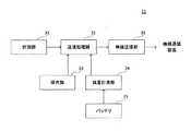
図8は、本発明の実施の形態に係るセンサ管理装置の構成を示す図である。 FIG. 8 is a diagram showing a configuration of the sensor management apparatus according to the embodiment of the present invention.
図8を参照して、センサ管理装置12は、受信部21と、処理部(判断部)22と、表示制御部23と、記憶部25とを備える。 With reference to FIG. 8, the
受信部21は、センサ11による計測結果を示すセンサ情報を受信する。具体的には、たとえば、受信部21は、計測結果情報、バッテリ情報および通信品質情報を含むセンサ情報を無線通信装置14から受信し、受信したセンサ情報を処理部22および記憶部25へ出力する。記憶部25は、受信部21から受けたセンサ情報を記憶する。 The receiving
処理部22は、たとえば、無線通信装置14から受信したセンサ情報に基づいて、たとえば、図2に示す画面Pi2の内容を含む表示情報Lを作成し、作成した表示情報Lを表示制御部23へ出力する。 For example, based on the sensor information received from the
表示制御部23は、受信部21によって受信されたセンサ情報の示す計測結果とセンサ11とを対応付けた画面を表示する制御を行う。 The
たとえば、表示制御部23は、処理部22から受けた表示情報Lをディスプレイ13へ送信する。ディスプレイ13には、たとえば、図2に示す画面Pi2が表示される。画面Pi2における表示部Au1〜Au8には、センサ情報の示す計測結果とセンサ11とを対応付けた内容が表示される。 For example, the
処理部22は、たとえば、センサ11Kからのセンサ情報を受信部21から受けてから、所定時間センサ11Kからの新たなセンサ情報を受信部21から受けなかった場合、受信部21がセンサ11Kからのセンサ情報を受信できなくなったと判断し、センサ11Kを受信不可センサとみなす。 For example, when the
処理部22は、受信部21がセンサ11Kからのセンサ情報を受信できなくなったと判断した場合、たとえば、記憶部25に保存されたセンサ11Kからの直近のセンサ情報の内容を確認し、センサ11Kからのセンサ情報を受信できなくなった原因、すなわち受信不可原因を判断する。 When the
具体的には、たとえば、センサ11Kからの直近のセンサ情報に含まれるバッテリ情報が、蓄電残量が少ないことを示す場合、センサ管理装置12は、センサ11Kの受信不可原因はバッテリ15の蓄電残量の不足であると判断する。 Specifically, for example, when the battery information included in the latest sensor information from the sensor 11K indicates that the remaining amount of power storage is low, the
また、処理部22は、たとえば、センサ11Kすなわち画面Pi2における表示部Au2に対応するセンサ11と同様に、表示部Au3,Au5,Au7に対応するセンサ11も受信不可センサとみなす。 The
処理部22は、たとえば、自己の判断内容に基づいて、図3に示す画面Pi3の内容を含む表示情報Mを作成し、作成した表示情報Mを表示制御部23へ出力する。 For example, the
表示制御部23は、センサ情報を受信部21が受信できなくなったセンサ11、すなわち受信不可センサであるセンサ11Kを認識可能となるようにディスプレイ13の画面の表示内容を変更する制御を行う。 The
具体的には、たとえば、表示制御部23は、受信不可センサと当該受信不可センサの計測結果とを対応付けた内容、つまり表示部Au2の内容をディスプレイ13の画面から削除する制御を行う。 Specifically, for example, the
このとき、表示制御部23の制御により表示される画面は、たとえば、受信不可センサのIDのリストつまり受信不可センサリストをさらに示す画面である。 At this time, the screen displayed under the control of the
また、このとき、表示制御部23の制御により表示される画面は、たとえば、センサ11Kからのセンサ情報を受信部21が受信できなくなった原因すなわちセンサ11Kの受信不可原因を示す画面である。たとえば、蓄電残量が少ないことを示すバッテリ情報が受信部21によって受信されていた場合、当該画面は、当該受信不可原因として、蓄電残量が少ない旨を示す。 At this time, the screen displayed by the control of the
具体的には、たとえば、表示制御部23は、表示情報Mをディスプレイ13へ送信する。また、処理部22は、センサ11と自己のセンサ管理装置12との通信品質を判断する。 Specifically, for example, the
具体的には、たとえば、処理部22は、受信部21がセンサ11Kからのセンサ情報を受信できなくなったと判断した場合において、センサ11Kからの直近のセンサ情報に含まれる通信品質情報が低いレベルのLQIを示す場合、センサ11Kと自己のセンサ管理装置12との通信品質が悪いと判断する。 Specifically, for example, when the
そして、処理部22は、自己の判断結果に基づいて表示情報Wを作成し、作成した表示情報Wを表示制御部23へ出力する。 Then, the
表示制御部23は、処理部22によってセンサ11Kとセンサ管理装置12との通信品質が悪いと判断された場合、当該センサ11の受信不可原因として、通信品質が悪い旨を示す画面を表示する制御を行う。 When the
具体的には、表示制御部23は、処理部22から受信した表示情報Wをディスプレイ13へ送信する。 Specifically, the
ディスプレイ13には、たとえば図3に示す画面Pi3と以下の点が異なる画面が表示される。すなわち、当該画面では、リスト表示エリアGdにおいて表示される受信不可センサリストに、センサ11Kの受信不可原因として、通信品質が悪い旨が表示される。 On the
また、処理部22は、受信部21がセンサ11Kからのセンサ情報を受信できなくなったと判断した場合において、センサ11Kからの直近のセンサ情報に含まれるバッテリ情報が、蓄電残量が少ないことを示しておらず、かつ、当該センサ情報に含まれる通信品質情報が、LQIのレベルが低いことを示していない場合、センサ11Kは故障していると判断する。 In addition, when the
そして、処理部22は、自己の判断結果に基づいて、表示情報Uを作成し、作成した表示情報Uを表示制御部23へ出力する。 Then, the
表示制御部23は、たとえば、センサ11の受信不可原因として、センサ11Kが故障している旨を画面に表示する制御を行う。具体的には、たとえば、表示制御部23は、処理部22から受信した表示情報Uをディスプレイ13へ送信する。 For example, the
ディスプレイ13には、たとえば図3に示す画面Pi3と以下の点が異なる画面が表示される。すなわち、当該画面では、リスト表示エリアGdにおいて表示される受信不可センサリストに、センサ11Kの受信不可原因として、故障している旨が表示される。 On the
なお、処理部22は、受信部21がセンサ11Kからのセンサ情報を受信できなくなったと判断した場合において、センサ11Kからの直近のセンサ情報に含まれるバッテリ情報が蓄電残量が少ないことを示しておらず、かつ、当該センサ情報に含まれる通信品質情報がLQIのレベルが低いことを示していない場合に、センサ11Kの受信不可原因は不明であると判断してもよい。 Note that the
この場合、表示制御部23は、センサ11の受信不可原因として、センサ11Kが故障している旨の代わりに、センサ11の受信不可原因が不明である旨を画面に表示する制御を行う。 In this case, the
ユーザがセンサ11Kに対して電源をオフするための操作を行った場合、センサ11は、動作を停止する前に、自己のIDおよび電源がオフされた旨を示すオフ情報を含む動作停止情報を作成し、作成した動作停止情報を無線通信装置14へ送信する。 When the user performs an operation for turning off the power to the sensor 11K, the
受信部21は、たとえば、センサ11から無線通信装置14経由で動作停止情報を受信し、受信した動作停止情報を処理部22へ出力する。 For example, the receiving
表示制御部23は、受信部21によって動作停止情報が受信された場合、受信不可原因としてセンサ11の電源がオフされた旨を示す画面を表示する制御を行う。 When the operation stop information is received by the
具体的には、処理部22は、センサ11Kからの動作停止情報を受信部21から受けると、センサ11Kの電源がオフされたことによってセンサ11Kからのセンサ情報を受信部21が受信できなくなったと認識する。 Specifically, when the
そして、処理部22は、ディスプレイ13の表示内容を示す表示情報Nを作成し、作成した表示情報Nを表示制御部23へ送信する。表示制御部23は、処理部22から受信した表示情報Nをディスプレイ13へ送信する。 Then, the
ディスプレイ13には、たとえば図3に示す画面Pi3と以下の点が異なる画面が表示される。すなわち、当該画面では、リスト表示エリアGdにおいて表示される受信不可センサリストに、センサ11Kの受信不可原因として、センサ11Kの電源がオフされた旨が表示される。 On the
処理部22は、たとえば、ディスプレイ13に図3に示す画面Pi3が表示されている場合において、センサ11Kからのセンサ情報を受信部21から受けると、受信部21がセンサ11Kからのセンサ情報を再び受信することができるようになったと判断する。 For example, when the screen Pi3 shown in FIG. 3 is displayed on the
そして、処理部22は、自己の判断内容に基づいて、表示情報Pを作成し、作成した表示情報Pを表示制御部23へ出力する。 Then, the
表示制御部23は、センサ情報を受信部21が再び受信できるようになったセンサ11に関する画面の表示内容を変更前に戻す制御を行う。具体的には、表示制御部23は、処理部22から受けた表示情報Pをディスプレイ13へ送信する。 The
ディスプレイ13には、たとえば図3に示す画面Pi3と以下の点が異なる画面が表示される。すなわち、当該画面では、表示部Au2にボタンBu2とセンサ11KのIDとが表示される。 On the
図9は、本発明の実施の形態に係る監視システムにおけるセンサの構成を示す図である。 FIG. 9 is a diagram showing a configuration of a sensor in the monitoring system according to the embodiment of the present invention.
図9を参照して、センサ11は、計測部31と、送信処理部32と、操作部33と、残量計測部34と、無線送信部35とを備える。 With reference to FIG. 9, the
計測部31は、監視対象に関する計測を行い、計測結果を示す計測結果情報を送信処理部32へ出力する。 The
残量計測部34は、バッテリ15の電圧を計測し、計測した電圧を示すバッテリ情報を作成する。そして、残量計測部34は、作成したバッテリ情報を送信処理部32へ出力する。 The remaining
送信処理部32は、自己のセンサ11のID、計測部31から受けた計測結果情報、および残量計測部34から受けたバッテリ情報を含むセンサ情報を作成し、作成したセンサ情報を無線送信部35へ出力する。 The
無線送信部35は、送信処理部32から受けたセンサ情報を含む無線信号を無線通信装置14へ送信する。 The
操作部33は、自己のセンサ11の電源をオフするための操作をユーザから受けると、当該操作の内容を送信処理部32へ通知する。 When the
送信処理部32は、操作部33から当該通知を受けて、自己のセンサ11のIDと、自己のセンサ11の電源がオフされた旨を示すオフ情報とを含む動作停止情報を作成し、作成した動作停止情報を無線送信部35へ出力する。 Upon receiving the notification from the
無線送信部35は、送信処理部32から受けた動作停止情報を含む無線信号をセンサ管理装置12へ送信する。 The
なお、本発明の実施の形態に係る監視システム101では、センサ11と無線通信装置14とは無線により接続される構成であるとしたが、これに限定するものではなく、有線により接続される構成であってもよい。 In the
また、本発明の実施の形態に係る監視システム101では、無線通信装置14とセンサ管理装置12とは有線により接続される構成であるとしたが、これに限定するものではなく、無線により接続される構成であってもよい。 In the
また、本発明の実施の形態に係る監視システム101は、無線通信装置14を備える構成であるとしたがこれに限定するものではなく、無線通信装置14を備えない構成であってもよい。この場合、センサ11は、センサ情報および動作停止情報を直接センサ管理装置12へ送信する。 Moreover, although the
また、本発明の実施の形態に係るセンサ11は、無線送信部35を備える構成であるとしたが、これに限定するものではなく、無線送信部35を備えない構成であってもよい。この場合、送信処理部32は、センサ11の外部に設けられた無線送信部35へセンサ情報および動作停止情報を送信する。 In addition, the
また、本発明の実施の形態に係るセンサ11は、バッテリ15を備える構成であるとしたが、これに限定するものではなく、バッテリ15を備えない構成であってもよい。この場合、センサ11は、外部から供給された電力により動作する。 Further, the
ところで、特許文献1に記載の技術において、あるセンサからの計測結果が何らかの原因により表示側で取得できなくなる場合がある。しかしながら、特許文献1には、このような問題点を解決するための構成は開示されていない。 By the way, in the technique described in
これに対して、本発明の実施の形態に係るセンサ管理装置では、受信部21は、センサ11による計測結果を示すセンサ情報を受信する。表示制御部23は、受信部21によって受信されたセンサ情報の示す計測結果とセンサ11とを対応付けた画面を表示する制御を行う。表示制御部23は、センサ情報を受信部21が受信できなくなったセンサ11を認識可能となるように画面の表示内容を変更する制御を行う。 On the other hand, in the sensor management device according to the embodiment of the present invention, the receiving
また、本発明の実施の形態に係る監視システムでは、センサ11は、自己の計測結果を示すセンサ情報をセンサ管理装置12へ送信する。センサ管理装置12は、センサ11から送信されたセンサ情報を受信し、受信したセンサ情報の示す計測結果とセンサ11とを対応付けた画面を表示する制御を行う。センサ管理装置12は、センサ情報を自己が受信できなくなったセンサ11を認識可能となるように画面の表示内容を変更する制御を行う。 In the monitoring system according to the embodiment of the present invention, the
このような構成により、たとえば、センサ管理装置12へのセンサ情報の伝送が停止したセンサ11と、当該伝送が継続しているセンサ11とをユーザが容易に識別することができる。また、たとえば、ユーザは、センサ11からのセンサ情報の伝送が停止した場合に、伝送が停止した原因の調査等、当該センサ11を復旧させるために必要な作業に速やかに取り掛かることができるため、当該センサ11による計測結果を取得できない期間を短縮することができる。 With such a configuration, for example, the user can easily identify the
したがって、本発明の実施の形態に係るセンサ管理装置および監視システムでは、センサによる計測結果を画面に表示する構成において、センサの計測結果を表示側で取得できなくなった状況においてユーザを支援することができる。 Therefore, in the sensor management device and the monitoring system according to the embodiment of the present invention, in the configuration in which the measurement result of the sensor is displayed on the screen, the user can be supported in a situation where the measurement result of the sensor cannot be acquired on the display side. it can.
また、本発明の実施の形態に係るセンサ管理装置では、表示制御部23は、センサ情報を受信部21が受信できなくなったセンサ11と計測結果とを対応付けた内容を画面から削除する制御を行う。 Further, in the sensor management device according to the embodiment of the present invention, the
このような構成により、たとえば、センサ管理装置12へのセンサ情報の伝送が継続しているセンサ11をユーザに認識させることができ、また、画面表示が煩雑になっている場合には、煩雑さを解消することができる。 With such a configuration, for example, it is possible to make the user recognize the
また、アプリケーションAPを再起動させることなく、ボタン表示エリアAdにおける当該伝送の停止したセンサ11に対応する表示を削除することができるため、アプリケーションAPを再起動させる手間を省くことができる。 Further, since the display corresponding to the
また、本発明の実施の形態に係るセンサ管理装置では、表示制御部23は、センサ情報を受信部21が受信できなくなった原因をさらに示す画面を表示する制御を行う。 Further, in the sensor management device according to the embodiment of the present invention, the
このような構成により、たとえば、ユーザは、センサ11からのセンサ情報の伝送が停止した原因を自ら調査することなく容易に把握することができるため、センサ情報の伝送の復旧を効率的に行うことができる。 With such a configuration, for example, the user can easily grasp the reason why the transmission of the sensor information from the
また、本発明の実施の形態に係るセンサ管理装置では、受信部21は、センサ11の電源がオフされた旨を示すオフ情報をセンサ11から受信する。表示制御部23は、受信部21によってオフ情報が受信された場合、上記原因として、センサ11の電源がオフされた旨を示す画面を表示する制御を行う。 In the sensor management device according to the embodiment of the present invention, the
このような構成により、ユーザは、センサ11からのセンサ情報の伝送が停止した原因が、当該センサ11の電源がオフされたことであることを容易に把握することができる。 With such a configuration, the user can easily grasp that the cause of the stop of transmission of sensor information from the
また、本発明の実施の形態に係るセンサ管理装置では、処理部(判断部)22は、センサ11と自己のセンサ管理装置12との通信品質を判断する。表示制御部23は、処理部22によって通信品質が悪いと判断された場合、上記原因として通信品質が悪い旨を示す画面を表示する制御を行う。 In the sensor management device according to the embodiment of the present invention, the processing unit (determination unit) 22 determines the communication quality between the
このような構成により、ユーザは、センサ11からのセンサ情報の伝送が停止した原因が、当該センサ11とセンサ管理装置12との通信品質の悪化であることを容易に把握することができる。 With such a configuration, the user can easily grasp that the cause of the stop of the transmission of the sensor information from the
また、本発明の実施の形態に係るセンサ管理装置では、受信部21は、センサ11のバッテリの蓄電残量に関するバッテリ情報をセンサ11から受信する。表示制御部23は、蓄電残量が少ないことを示すバッテリ情報が受信部21によって受信された場合、上記原因として蓄電残量が少ない旨を示す画面を表示する制御を行う。 In the sensor management device according to the embodiment of the present invention, the
このような構成により、ユーザは、センサ11からのセンサ情報の伝送が停止した原因が、当該センサ11におけるバッテリの蓄電残量の不足であることを容易に把握することができる。 With such a configuration, the user can easily grasp that the cause of the stop of the transmission of the sensor information from the
また、本発明の実施の形態に係るセンサ管理装置では、表示制御部23は、上記原因としてセンサ11が故障している旨を示すか、または上記原因の代わりに、原因が不明である旨を示す画面を表示する制御を行う。 In the sensor management device according to the embodiment of the present invention, the
このような構成により、ユーザは、センサ11からのセンサ情報の伝送が停止した原因が、センサ管理装置12によって判断可能な原因以外の原因であることを認識することができる。 With such a configuration, the user can recognize that the cause of the stop of transmission of sensor information from the
また、本発明の実施の形態に係るセンサ管理装置では、表示制御部23は、センサ情報を受信部21が受信できなくなったセンサ11の識別情報のリストである受信不可センサリストをさらに示す画面を表示する制御を行う。 Further, in the sensor management device according to the embodiment of the present invention, the
このような構成により、ユーザは、センサ管理装置12へのセンサ情報の伝送が停止したセンサ11の一覧を確認することができる。 With such a configuration, the user can check a list of
また、本発明の実施の形態に係るセンサ管理装置では、表示制御部23は、センサ情報を受信部21が再び受信できるようになったセンサ11に関する画面の表示内容を変更前に戻す制御を行う。 Further, in the sensor management device according to the embodiment of the present invention, the
このような構成により、たとえば、ユーザは、センサ管理装置12へのセンサ情報の伝送が再開されたことを認識することができる。また、センサ管理装置12においてセンサ情報を再び受信できるようになった場合に、画面の表示を自動で更新することができる。 With such a configuration, for example, the user can recognize that transmission of sensor information to the
また、本発明の実施の形態に係るセンサでは、計測部31は計測を行う。送信処理部32は、計測部31による計測結果を示すセンサ情報を、センサ情報の示す計測結果とセンサ11とを対応付けた画面を表示する制御を行うことが可能なセンサ管理装置12へ送信する処理を行う。送信処理部32は、自己のセンサ11の電源がオフされた旨を示すオフ情報と自己のセンサ11の識別情報とをセンサ管理装置12へ送信する処理を行う。 In the sensor according to the embodiment of the present invention, the
このような構成により、たとえば、ユーザは、センサ11からのセンサ情報の伝送が停止した場合に、当該伝送の停止の原因が、センサ11の電源がオフされたことであることを容易に把握することができる。 With such a configuration, for example, when the transmission of sensor information from the
したがって、本発明の実施の形態に係るセンサでは、センサによる計測結果を画面に表示する構成において、センサの計測結果を表示側で取得できなくなった状況においてユーザを支援することができる。 Therefore, the sensor according to the embodiment of the present invention can support the user in a situation where the measurement result of the sensor cannot be obtained on the display side in the configuration in which the measurement result by the sensor is displayed on the screen.
上記実施の形態は、すべての点で例示であって制限的なものではないと考えられるべきである。本発明の範囲は、上記説明ではなく特許請求の範囲によって示され、特許請求の範囲と均等の意味および範囲内でのすべての変更が含まれることが意図される。 The above embodiment should be considered as illustrative in all points and not restrictive. The scope of the present invention is defined by the terms of the claims, rather than the description above, and is intended to include any modifications within the scope and meaning equivalent to the terms of the claims.
以上の説明は、以下に付記する特徴を含む。 The above description includes the following features.
[付記1]
センサによる計測結果を示すセンサ情報を受信する受信部と、
前記受信部によって受信された前記センサ情報の示す前記計測結果と前記センサとを対応付けた画面を表示する制御を行う表示制御部とを備え、
前記受信部は、1または複数の前記センサから前記センサ情報を受信し、
前記表示制御部は、前記センサ情報を前記受信部が受信できなくなった前記センサと前記計測結果とを対応付けた内容の表示態様を、他の前記センサと前記計測結果とを対応付けた内容とは異なる表示態様とし、
前記受信部は、前記センサから無線で送信された前記センサ情報を受信する、センサ管理装置。[Appendix 1]
A receiving unit for receiving sensor information indicating a measurement result by the sensor;
A display control unit that performs control to display a screen in which the measurement result indicated by the sensor information received by the reception unit is associated with the sensor;
The receiving unit receives the sensor information from one or more sensors,
The display control unit includes a display mode of the content in which the sensor information is no longer received by the receiving unit and the content in which the measurement result is associated, and the content in which the other sensor is associated with the measurement result. Have different display styles,
The said receiving part is a sensor management apparatus which receives the said sensor information transmitted by radio | wireless from the said sensor.
[付記2]
センサであって、
計測を行う計測部と、
前記計測部による計測結果を示すセンサ情報を、前記センサ情報の示す前記計測結果と前記センサとを対応付けた画面を表示する制御を行うことが可能なセンサ管理装置へ送信する処理を行う送信処理部とを備え、
前記送信処理部は、さらに、自己のセンサの電源がオフされた旨を示すオフ情報と自己のセンサの識別情報とを前記センサ管理装置へ送信する処理を行い、
前記センサ情報は、前記センサ管理装置へ無線で送信される、センサ。[Appendix 2]
A sensor,
A measurement unit for measuring,
A transmission process for performing processing for transmitting sensor information indicating a measurement result by the measurement unit to a sensor management apparatus capable of performing control to display a screen in which the measurement result indicated by the sensor information is associated with the sensor. With
The transmission processing unit further performs processing for transmitting to the sensor management device off information indicating that the power of its own sensor has been turned off and identification information of its own sensor,
The sensor information is wirelessly transmitted to the sensor management device.
11,11K センサ
12 センサ管理装置
13 ディスプレイ
14 無線通信装置
15 バッテリ
21 受信部
22 処理部
23 表示制御部
25 記憶部
31 計測部
32 送信処理部
33 操作部
34 残量計測部
35 無線送信部
101 監視システム11,
Claims (15)
Translated fromJapanese前記受信部によって受信された前記センサ情報の示す前記計測結果と前記センサとを対応付けた画面を表示する制御を行う表示制御部とを備え、
前記表示制御部は、前記センサ情報を前記受信部が受信できなくなった前記センサを認識可能となるように前記画面の表示内容を変更する制御を行う、センサ管理装置。A receiving unit for receiving sensor information indicating a measurement result by the sensor;
A display control unit that performs control to display a screen in which the measurement result indicated by the sensor information received by the reception unit is associated with the sensor;
The said display control part is a sensor management apparatus which performs control which changes the display content of the said screen so that the said sensor which the said receiving part cannot receive the said sensor information can be recognized now.
前記表示制御部は、前記受信部によって前記オフ情報が受信された場合、前記原因として、前記センサの電源がオフされた旨を示す前記画面を表示する制御を行う、請求項3に記載のセンサ管理装置。The receiver further receives off information from the sensor indicating that the power of the sensor is turned off,
The sensor according to claim 3, wherein the display control unit performs control to display the screen indicating that the power of the sensor is turned off as the cause when the off information is received by the receiving unit. Management device.
前記センサと自己のセンサ管理装置との通信品質を判断する判断部を備え、
前記表示制御部は、前記判断部によって前記通信品質が悪いと判断された場合、前記原因として前記通信品質が悪い旨を示す前記画面を表示する制御を行う、請求項3または請求項4に記載のセンサ管理装置。The sensor management device further includes:
A determination unit for determining communication quality between the sensor and its own sensor management device;
The said display control part performs control which displays the said screen which shows that the said communication quality is bad as the said cause, when the said communication part judges that the said communication quality is bad. Sensor management device.
前記表示制御部は、前記蓄電残量が少ないことを示す前記バッテリ情報が前記受信部によって受信された場合、前記原因として前記蓄電残量が少ない旨を示す前記画面を表示する制御を行う、請求項3から請求項5のいずれか1項に記載のセンサ管理装置。The receiving unit further receives battery information on the remaining amount of charge of the battery of the sensor from the sensor,
The display control unit performs control to display the screen indicating that the remaining amount of storage is low as the cause when the battery information indicating that the remaining amount of storage is low is received by the reception unit. The sensor management device according to any one of claims 3 to 5.
計測を行う計測部と、
前記計測部による計測結果を示すセンサ情報を、前記センサ情報の示す前記計測結果と前記センサとを対応付けた画面を表示する制御を行うことが可能なセンサ管理装置へ送信する処理を行う送信処理部とを備え、
前記送信処理部は、さらに、自己のセンサの電源がオフされた旨を示すオフ情報と自己のセンサの識別情報とを前記センサ管理装置へ送信する処理を行う、センサ。A sensor,
A measurement unit for measuring,
A transmission process for performing processing for transmitting sensor information indicating a measurement result by the measurement unit to a sensor management apparatus capable of performing control to display a screen in which the measurement result indicated by the sensor information is associated with the sensor. With
The transmission processing unit further performs processing for transmitting off information indicating that the power of its own sensor is turned off and identification information of its own sensor to the sensor management device.
センサ管理装置とを備え、
前記センサは、自己の計測結果を示すセンサ情報を前記センサ管理装置へ送信し、
前記センサ管理装置は、前記センサから送信された前記センサ情報を受信し、受信した前記センサ情報の示す前記計測結果と前記センサとを対応付けた画面を表示する制御を行い、
前記センサ管理装置は、前記センサ情報を自己が受信できなくなった前記センサを認識可能となるように前記画面の表示内容を変更する制御を行う、監視システム。A sensor,
A sensor management device,
The sensor transmits sensor information indicating its own measurement result to the sensor management device,
The sensor management device performs control to receive the sensor information transmitted from the sensor and display a screen in which the measurement result indicated by the received sensor information is associated with the sensor.
The monitoring system, wherein the sensor management device performs control to change display content of the screen so that the sensor that can no longer receive the sensor information can be recognized.
センサによる計測結果を示すセンサ情報を受信するステップと、
受信した前記センサ情報の示す前記計測結果と前記センサとを対応付けた画面を表示する制御を行うステップと、
前記センサ情報を受信できなくなった前記センサを認識可能となるように前記画面の表示内容を変更する制御を行うステップとを含む、センサ管理方法。A sensor management method in a sensor management device,
Receiving sensor information indicating a measurement result by the sensor;
Performing control to display a screen in which the measurement result indicated by the received sensor information is associated with the sensor;
Performing a control to change the display content of the screen so that the sensor that can no longer receive the sensor information can be recognized.
センサによる計測結果を示すセンサ情報を受信するステップと、
受信した前記センサ情報の示す前記計測結果と前記センサとを対応付けた画面を表示する制御を行うステップと、
前記センサ情報を受信できなくなった前記センサを認識可能となるように前記画面の表示内容を変更する制御を行うステップとを実行させるための、センサ管理プログラム。A sensor management program used in a sensor management device, which is
Receiving sensor information indicating a measurement result by the sensor;
Performing control to display a screen in which the measurement result indicated by the received sensor information is associated with the sensor;
And a step of performing a control to change the display content of the screen so that the sensor that can no longer receive the sensor information can be recognized.
計測を行うステップと、
計測結果を示すセンサ情報を、前記センサ情報の示す前記計測結果と前記センサとを対応付けた画面を表示する制御を行うことが可能なセンサ管理装置へ送信する処理を行うステップと、
前記センサの電源がオフされた旨を示すオフ情報と前記センサの識別情報とを前記センサ管理装置へ送信するステップとを含む、監視方法。A monitoring method in a sensor,
A step of measuring,
Performing a process of transmitting sensor information indicating a measurement result to a sensor management apparatus capable of performing control to display a screen in which the measurement result indicated by the sensor information is associated with the sensor; and
And a step of transmitting off information indicating that the power of the sensor is turned off and identification information of the sensor to the sensor management device.
計測を行うステップと、
計測結果を示すセンサ情報を、前記センサ情報の示す前記計測結果と前記センサとを対応付けた画面を表示する制御を行うことが可能なセンサ管理装置へ送信する処理を行うステップと、
前記センサの電源がオフされた旨を示すオフ情報と前記センサの識別情報とを前記センサ管理装置へ送信するステップとを実行させるための、監視プログラム。A monitoring program used in a sensor, to a computer,
A step of measuring,
Performing a process of transmitting sensor information indicating a measurement result to a sensor management apparatus capable of performing control to display a screen in which the measurement result indicated by the sensor information is associated with the sensor; and
A monitoring program for executing off-information indicating that the power of the sensor is turned off and transmitting the sensor identification information to the sensor management device.
Priority Applications (3)
| Application Number | Priority Date | Filing Date | Title |
|---|---|---|---|
| JP2015040824AJP2016162249A (en) | 2015-03-03 | 2015-03-03 | Sensor management device, sensor, monitoring system, sensor management method, sensor management program, monitoring method, and monitoring program |
| US15/112,207US9992559B2 (en) | 2015-03-03 | 2015-11-10 | Sensor management device, sensor, monitoring system, sensor management method, sensor management program, monitoring method, and monitoring program |
| PCT/JP2015/081589WO2016139845A1 (en) | 2015-03-03 | 2015-11-10 | Sensor management apparatus, sensor, monitoring system, sensor management method, sensor management program, monitoring method, and monitoring program |
Applications Claiming Priority (1)
| Application Number | Priority Date | Filing Date | Title |
|---|---|---|---|
| JP2015040824AJP2016162249A (en) | 2015-03-03 | 2015-03-03 | Sensor management device, sensor, monitoring system, sensor management method, sensor management program, monitoring method, and monitoring program |
Related Child Applications (1)
| Application Number | Title | Priority Date | Filing Date |
|---|---|---|---|
| JP2018082415ADivisionJP6760327B2 (en) | 2018-04-23 | 2018-04-23 | Sensor management device, monitoring system, sensor management method and sensor management program |
Publications (2)
| Publication Number | Publication Date |
|---|---|
| JP2016162249Atrue JP2016162249A (en) | 2016-09-05 |
| JP2016162249A5 JP2016162249A5 (en) | 2017-12-21 |
Family
ID=56847124
Family Applications (1)
| Application Number | Title | Priority Date | Filing Date |
|---|---|---|---|
| JP2015040824APendingJP2016162249A (en) | 2015-03-03 | 2015-03-03 | Sensor management device, sensor, monitoring system, sensor management method, sensor management program, monitoring method, and monitoring program |
Country Status (3)
| Country | Link |
|---|---|
| US (1) | US9992559B2 (en) |
| JP (1) | JP2016162249A (en) |
| WO (1) | WO2016139845A1 (en) |
Families Citing this family (3)
| Publication number | Priority date | Publication date | Assignee | Title |
|---|---|---|---|---|
| JP6197827B2 (en)* | 2015-05-19 | 2017-09-20 | 住友電気工業株式会社 | Sensor management apparatus, sensor management method, and sensor management program |
| FR3068163B1 (en)* | 2017-06-23 | 2019-12-20 | Diehl Metering Sas | METHOD AND SYSTEM FOR COLLECTING DATA PROVIDED BY SENSORS |
| EP4002892B1 (en)* | 2019-07-19 | 2025-05-07 | OMRON Corporation | Wireless communication device and wireless communication system |
Citations (12)
| Publication number | Priority date | Publication date | Assignee | Title |
|---|---|---|---|---|
| JPH06274779A (en)* | 1993-03-19 | 1994-09-30 | Nohmi Bosai Ltd | Terminal equipment for fir alarm equipment |
| JPH06314390A (en)* | 1993-04-30 | 1994-11-08 | Ricoh Elemex Corp | Gas leak alarm system |
| JPH10320042A (en)* | 1997-05-19 | 1998-12-04 | Toshiba Eng Co Ltd | Plant device operation state display device |
| JP2000154969A (en)* | 1998-11-20 | 2000-06-06 | Sanyo Electric Co Ltd | Controller for equipment |
| JP2001160190A (en)* | 1999-12-03 | 2001-06-12 | Sharp Corp | Monitoring terminal, communication module and home control system |
| JP2003018164A (en)* | 2001-07-03 | 2003-01-17 | Toshiba Corp | Distributed terminal equipment |
| JP2005165611A (en)* | 2003-12-02 | 2005-06-23 | Tokyo Gas Co Ltd | Alarm |
| JP2010533903A (en)* | 2007-06-28 | 2010-10-28 | マイクロソフト コーポレーション | Learning and reasoning about the situation-dependent reliability of sensors |
| JP2011179215A (en)* | 2010-03-01 | 2011-09-15 | Komatsu Ltd | Monitor system and status display method |
| JP2012083846A (en)* | 2010-10-07 | 2012-04-26 | Base Technology Inc | Sensor network system and sensor node unit used therefor |
| JP2012118851A (en)* | 2010-12-02 | 2012-06-21 | Hochiki Corp | Monitoring system and alarm |
| JP2014170348A (en)* | 2013-03-04 | 2014-09-18 | Yazaki Energy System Corp | Alarm |
Family Cites Families (7)
| Publication number | Priority date | Publication date | Assignee | Title |
|---|---|---|---|---|
| JP3029716B2 (en)* | 1991-11-01 | 2000-04-04 | ホーチキ株式会社 | Wireless analog sensor |
| JPH10238179A (en) | 1997-02-28 | 1998-09-08 | Matsushita Electric Works Ltd | Home control system |
| WO2008154312A1 (en)* | 2007-06-08 | 2008-12-18 | Dexcom, Inc. | Integrated medicament delivery device for use with continuous analyte sensor |
| JP5456414B2 (en) | 2009-03-31 | 2014-03-26 | 日本ノーベル株式会社 | Display method and monitoring device for area monitoring |
| JP5343920B2 (en)* | 2010-04-27 | 2013-11-13 | 株式会社デンソー | Failure sign detection device |
| EP2586018B1 (en)* | 2010-06-25 | 2019-09-11 | Industrial Scientific Corporation | A multi-sense environmental monitoring device and method |
| US20140343736A1 (en)* | 2012-01-26 | 2014-11-20 | Timothy Meyer | Substance Control System |
- 2015
- 2015-03-03JPJP2015040824Apatent/JP2016162249A/enactivePending
- 2015-11-10WOPCT/JP2015/081589patent/WO2016139845A1/ennot_activeCeased
- 2015-11-10USUS15/112,207patent/US9992559B2/enactiveActive
Patent Citations (12)
| Publication number | Priority date | Publication date | Assignee | Title |
|---|---|---|---|---|
| JPH06274779A (en)* | 1993-03-19 | 1994-09-30 | Nohmi Bosai Ltd | Terminal equipment for fir alarm equipment |
| JPH06314390A (en)* | 1993-04-30 | 1994-11-08 | Ricoh Elemex Corp | Gas leak alarm system |
| JPH10320042A (en)* | 1997-05-19 | 1998-12-04 | Toshiba Eng Co Ltd | Plant device operation state display device |
| JP2000154969A (en)* | 1998-11-20 | 2000-06-06 | Sanyo Electric Co Ltd | Controller for equipment |
| JP2001160190A (en)* | 1999-12-03 | 2001-06-12 | Sharp Corp | Monitoring terminal, communication module and home control system |
| JP2003018164A (en)* | 2001-07-03 | 2003-01-17 | Toshiba Corp | Distributed terminal equipment |
| JP2005165611A (en)* | 2003-12-02 | 2005-06-23 | Tokyo Gas Co Ltd | Alarm |
| JP2010533903A (en)* | 2007-06-28 | 2010-10-28 | マイクロソフト コーポレーション | Learning and reasoning about the situation-dependent reliability of sensors |
| JP2011179215A (en)* | 2010-03-01 | 2011-09-15 | Komatsu Ltd | Monitor system and status display method |
| JP2012083846A (en)* | 2010-10-07 | 2012-04-26 | Base Technology Inc | Sensor network system and sensor node unit used therefor |
| JP2012118851A (en)* | 2010-12-02 | 2012-06-21 | Hochiki Corp | Monitoring system and alarm |
| JP2014170348A (en)* | 2013-03-04 | 2014-09-18 | Yazaki Energy System Corp | Alarm |
Also Published As
| Publication number | Publication date |
|---|---|
| US9992559B2 (en) | 2018-06-05 |
| WO2016139845A1 (en) | 2016-09-09 |
| US20170013330A1 (en) | 2017-01-12 |
Similar Documents
| Publication | Publication Date | Title |
|---|---|---|
| JP6310204B2 (en) | Method for collecting measurement data from a gateway device and a portable measurement device used in a measurement system | |
| JP6449232B2 (en) | Automatic recording and graphing of measurement data | |
| JP6582395B2 (en) | Measuring device and control method thereof, management device and control method thereof, and measuring system | |
| JP5374730B2 (en) | Electric appliance control system and electric appliance control method | |
| KR20210012200A (en) | Maintenance system for environment test apparatus using machine self check sensor and the control method thereof | |
| JP2016162249A (en) | Sensor management device, sensor, monitoring system, sensor management method, sensor management program, monitoring method, and monitoring program | |
| JP2004310439A (en) | Environmental monitoring system, data logger used in this system and its program | |
| JP6639952B2 (en) | Inspection system for alarm using mobile terminal and inspection method using the same | |
| JP6760327B2 (en) | Sensor management device, monitoring system, sensor management method and sensor management program | |
| JP2020088460A (en) | Status display system, communication failure identification method, and program | |
| JPWO2017109992A1 (en) | Maintenance support system, display device, and maintenance support method | |
| JP2017062619A (en) | Storage battery system, storage battery monitoring system, and storage battery information collection method | |
| KR101065485B1 (en) | Engine wireless monitoring system | |
| JP6521202B1 (en) | Information processing apparatus and abnormality visualization system | |
| EP3499928B1 (en) | Determining signal quality in a low-power wide-area network | |
| JP6237687B2 (en) | Sensor information processing apparatus, sensor information processing method, and sensor information processing program | |
| US12261466B2 (en) | Storage battery monitoring device and method for maintaining storage battery monitoring device | |
| JP6112552B2 (en) | Information collection system | |
| JP2019061425A (en) | Notification control apparatus, notification control system, notification control method, and notification control program | |
| JP2016149029A (en) | Automatic fire alarm system slave unit, master unit, and automatic fire alarm system using the same | |
| KR102713369B1 (en) | Apparatus and method for monitoring measuring instruments in factory | |
| JP6278151B1 (en) | Sensor information processing apparatus, sensor information processing method, and sensor information processing program | |
| JP6265835B2 (en) | Information processing apparatus, diagnosis order determination method, and control program | |
| CN111373426A (en) | Vendor selection | |
| JP2019008430A (en) | Housing equipment repair work support system |
Legal Events
| Date | Code | Title | Description |
|---|---|---|---|
| A521 | Request for written amendment filed | Free format text:JAPANESE INTERMEDIATE CODE: A523 Effective date:20171108 | |
| A621 | Written request for application examination | Free format text:JAPANESE INTERMEDIATE CODE: A621 Effective date:20171108 | |
| A871 | Explanation of circumstances concerning accelerated examination | Free format text:JAPANESE INTERMEDIATE CODE: A871 Effective date:20171108 | |
| A975 | Report on accelerated examination | Free format text:JAPANESE INTERMEDIATE CODE: A971005 Effective date:20171109 | |
| A131 | Notification of reasons for refusal | Free format text:JAPANESE INTERMEDIATE CODE: A131 Effective date:20171205 | |
| A521 | Request for written amendment filed | Free format text:JAPANESE INTERMEDIATE CODE: A523 Effective date:20171227 | |
| A02 | Decision of refusal | Free format text:JAPANESE INTERMEDIATE CODE: A02 Effective date:20180123 |