JP2016161595A - Optical scanning device and endoscope device - Google Patents
Optical scanning device and endoscope deviceDownload PDFInfo
- Publication number
- JP2016161595A JP2016161595AJP2015037286AJP2015037286AJP2016161595AJP 2016161595 AJP2016161595 AJP 2016161595AJP 2015037286 AJP2015037286 AJP 2015037286AJP 2015037286 AJP2015037286 AJP 2015037286AJP 2016161595 AJP2016161595 AJP 2016161595A
- Authority
- JP
- Japan
- Prior art keywords
- movable
- lens
- fixed
- reflector
- reflecting portion
- Prior art date
- Legal status (The legal status is an assumption and is not a legal conclusion. Google has not performed a legal analysis and makes no representation as to the accuracy of the status listed.)
- Pending
Links
Images


Landscapes
- Endoscopes (AREA)
- Instruments For Viewing The Inside Of Hollow Bodies (AREA)
- Mechanical Optical Scanning Systems (AREA)
- Mechanical Light Control Or Optical Switches (AREA)
Abstract
Description
Translated fromJapanese本発明は、光走査装置及び内視鏡装置に関する。 The present invention relates to an optical scanning device and an endoscope device.
現在、2次元の光走査をするための光走査装置が種々開発されている。例えば、特許文献1には、互いに対向する基板及び光学部材の間で光を反射させることにより、2次元の光走査を実現することが記載されている。具体的には、この基板は、回転軸が互いに異なる方向を向いている第1可動反射部及び第2可動反射部を備えている。そしてこの光走査装置は、第1可動反射部及び第2可動反射部それぞれの回転を制御することで、光走査をしている。 Currently, various optical scanning devices for two-dimensional optical scanning have been developed. For example, Patent Document 1 describes that two-dimensional optical scanning is realized by reflecting light between a substrate and an optical member facing each other. Specifically, the substrate includes a first movable reflecting portion and a second movable reflecting portion whose rotation axes are directed in different directions. This optical scanning device performs optical scanning by controlling the rotation of each of the first movable reflective portion and the second movable reflective portion.
さらに、特許文献2には、コリメータ光を光走査装置に入射することが記載されている。さらに、特許文献3には、コリメータレンズの位置を制御することにより、集光スポットの位置を制御することが記載されている。 Further, Patent Document 2 describes that collimator light is incident on an optical scanning device. Further, Patent Document 3 describes that the position of the focused spot is controlled by controlling the position of the collimator lens.
光走査装置及び内視鏡装置では、出射光が対物レンズを介して外部に出射される。そして一部の光走査装置及び一部の内視鏡装置では、対物レンズからの出射光の光軸方向に沿って集光スポットの位置を制御することが要求される。本発明者らは、対物レンズからの出射光の光軸方向に沿って集光スポットの位置を制御するための構造を検討した。 In the optical scanning device and the endoscope device, the emitted light is emitted to the outside through the objective lens. Some optical scanning devices and some endoscope devices are required to control the position of the focused spot along the optical axis direction of the light emitted from the objective lens. The present inventors examined a structure for controlling the position of the focused spot along the optical axis direction of the light emitted from the objective lens.
本発明は上記事情に鑑みてなされたものであり、その目的とするところは、光走査装置及び内視鏡装置において、対物レンズからの出射光の光軸方向に沿って集光スポットの位置を制御することにある。 The present invention has been made in view of the above circumstances, and an object of the present invention is to determine the position of a condensed spot along the optical axis direction of light emitted from an objective lens in an optical scanning device and an endoscope device. There is to control.
本発明に係る光走査装置は、第1可動反射部、第2可動反射部、第1固定反射部、第2固定反射部、第3固定反射部、第1レンズ、及び第2レンズを備えている。第1可動反射部は、反射面が回転可能である。第2可動反射部は、反射面が回転可能である。さらに、第2可動反射部は、回転軸が第1可動反射部の回転軸と交わる方向を向いている。さらに、第2可動反射部は、平面視で第1可動反射部と並んで配置されている。第1固定反射部は、平面視で第1可動反射部を介して第2可動反射部とは逆側に位置している。さらに、第1固定反射部は、入射光を第1可動反射部に向けて反射する。第2固定反射部は、平面視で第1可動反射部と第2可動反射部の間に配置されている。さらに、第2固定反射部は、第1可動反射部で反射された入射光を第2可動反射部に向けて反射する。第3固定反射部は、平面視で第2可動反射部を介して第1可動反射部とは逆側に配置されている。さらに、第3固定反射部は、第2可動反射部で反射された入射光を第2可動反射部から離れる方向に反射する。第1レンズは、平面視で第3固定反射部を介して第2可動反射部とは逆側に配置されている。さらに、第1レンズは、第3固定反射部で反射された入射光を集光する。第2レンズは、平面視で第3固定反射部と第1レンズの間に配置されている。さらに、第2レンズは、第3固定反射部で反射された入射光が入射する。さらに、第2レンズは、第3固定反射部で反射された入射光の光軸に沿って焦点が移動可能である。 An optical scanning device according to the present invention includes a first movable reflection unit, a second movable reflection unit, a first fixed reflection unit, a second fixed reflection unit, a third fixed reflection unit, a first lens, and a second lens. Yes. The first movable reflecting portion has a reflecting surface that is rotatable. The second movable reflecting portion can rotate the reflecting surface. Furthermore, the 2nd movable reflection part has faced the direction where a rotating shaft crosses the rotating shaft of a 1st movable reflecting part. Furthermore, the second movable reflecting portion is arranged side by side with the first movable reflecting portion in plan view. The first fixed reflection portion is located on the opposite side of the second movable reflection portion via the first movable reflection portion in plan view. Further, the first fixed reflection part reflects incident light toward the first movable reflection part. The second fixed reflection portion is disposed between the first movable reflection portion and the second movable reflection portion in plan view. Further, the second fixed reflection part reflects incident light reflected by the first movable reflection part toward the second movable reflection part. The third fixed reflection portion is disposed on the opposite side of the first movable reflection portion via the second movable reflection portion in plan view. Further, the third fixed reflection part reflects incident light reflected by the second movable reflection part in a direction away from the second movable reflection part. The first lens is disposed on the opposite side to the second movable reflecting portion via the third fixed reflecting portion in plan view. Further, the first lens condenses incident light reflected by the third fixed reflecting portion. The second lens is disposed between the third fixed reflector and the first lens in plan view. Furthermore, incident light reflected by the third fixed reflecting portion is incident on the second lens. Further, the focal point of the second lens is movable along the optical axis of the incident light reflected by the third fixed reflecting portion.
本発明に係る内視鏡装置は、光源及び上記した光走査装置を備える。光走査装置は、光源から入射された光を走査するとともに、光が観察対象で反射した反射光を取り出す。 An endoscope apparatus according to the present invention includes a light source and the above-described optical scanning device. The optical scanning device scans the light incident from the light source and extracts reflected light reflected by the observation target.
本発明によれば、光走査装置及び内視鏡装置において、対物レンズからの出射光の光軸方向に沿って集光スポットの位置を制御することができる。 ADVANTAGE OF THE INVENTION According to this invention, the position of a condensing spot can be controlled along the optical axis direction of the emitted light from an objective lens in an optical scanning device and an endoscope apparatus.
以下、本発明の実施の形態について、図面を用いて説明する。尚、すべての図面において、同様な構成要素には同様の符号を付し、適宜説明を省略する。 Hereinafter, embodiments of the present invention will be described with reference to the drawings. In all the drawings, the same reference numerals are given to the same components, and the description will be omitted as appropriate.
(第1の実施形態)
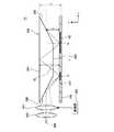
図1は、第1の実施形態に係る光走査装置10の構成を示す図である。光走査装置10は、第1可動反射部102、第2可動反射部104、第1固定反射部202、第2固定反射部204、第3固定反射部206、第1レンズ400、及び第2レンズ300を備えている。第1可動反射部102は、反射面が回転可能である。第2可動反射部104は、反射面が回転可能である。さらに、第2可動反射部104は、回転軸が第1可動反射部102の回転軸と交わる方向(例えば、第1可動反射部102の回転軸と直交する方向)を向いている。さらに、第2可動反射部104は、平面視で第1可動反射部102と並んで配置されている。第1固定反射部202は、平面視で第1可動反射部102を介して第2可動反射部104とは逆側に位置している。さらに、第1固定反射部202は、入射光を第1可動反射部102に向けて反射する。第2固定反射部204は、平面視で第1可動反射部102と第2可動反射部104の間に配置されている。さらに、第2固定反射部204は、第1可動反射部102で反射された入射光を第2可動反射部104に向けて反射する。第3固定反射部206は、平面視で第2可動反射部104を介して第1可動反射部102とは逆側に配置されている。さらに、第3固定反射部206は、第2可動反射部104で反射された入射光を第2可動反射部104から離れる方向に反射する。第1レンズ400は、平面視で第3固定反射部206を介して第2可動反射部104とは逆側に配置されている。さらに、第1レンズ400は、第3固定反射部206で反射された入射光を集光する。第2レンズ300は、平面視で第3固定反射部206と第1レンズ400の間に配置されている。さらに、第2レンズ300は、第3固定反射部206で反射された入射光が入射する。さらに、第2レンズ300は、第3固定反射部206で反射された入射光の光軸に沿って移動可能である。以下、詳細に説明する。(First embodiment)
FIG. 1 is a diagram illustrating a configuration of an
本実施形態において、平面視において第1固定反射部202、第1可動反射部102、第2固定反射部204、第2可動反射部104、及び第3固定反射部206は、一つの直線に沿って配置されている。このため、光走査装置10の幅(図1の紙面に対して直角な方向の幅)は、小さくなる。 In the present embodiment, the first
第1可動反射部102及び第2可動反射部104は、同一の基板100に形成されている。基板100は、例えばシリコン基板である。そして第1可動反射部102及び第2可動反射部104は、基板100を加工することにより形成されている。第1可動反射部102及び第2可動反射部104の構造の詳細については後述する。 The first
第1固定反射部202、第2固定反射部204、及び第3固定反射部206は、一つの光学部材200の外面(第1反射面、第2反射面、及び第3反射面)として形成されている。光学部材200は、例えばセラミックス、金属、ガラス、又は樹脂により形成されている。そして第1固定反射部202、第2固定反射部204、及び第3固定反射部206は、光学部材200の外面のうち基板100に対向している面に金属膜(例えばAl膜)を蒸着法などで形成したものである。第1固定反射部202、第2固定反射部204、及び第3固定反射部206は、いずれも平面であるが、向きが互いに異なる。 The first
本実施形態において、第2固定反射部204は基板100と平行である。そして第2固定反射部204に対する第1固定反射部202の角度θ1は、第2固定反射部204に対する第3固定反射部206の角度θ2と等しい。ただし、第1固定反射部202と第3固定反射部206は互いに逆側を向いている。角度θ1及びθ2は、例えば12.4°以上12.6°以下である。ただし角度θ1及びθ2はこの範囲に限定されない。そして、第2固定反射部204のうち光が入射する部分から第2可動反射部104のうち光が入射する部分までの距離をL、第2固定反射部204から第2可動反射部104までの距離をH、第2固定反射部204の法線に対する光の角度をθ3とすると、以下の関係が成り立つ。
tanθ3=L/H・・・(1)
θ1=(π/2−θ3)/2・・・(2)In the present embodiment, the second fixed
tan θ3 = L / H (1)
θ1 = (π / 2−θ3 ) / 2 (2)
第1レンズ400は、対物レンズであり、本図に示す例では、両凸レンズである。さらに第1レンズ400は、第3固定反射部206に対する位置が固定されており、第3固定反射部206からの反射光の光軸に沿って移動することができない。これに対して、第2レンズ300は、駆動部302によって、第3固定反射部206からの反射光の光軸に沿って移動することができる。駆動部302による第2レンズ300の移動方法の例には、圧電素子による駆動、電磁式モータ及びネジによる回転移動、リニアモータ移動、並びにマイクロメータ及びバネの組み合わせによる移動が含まれる。ただし、駆動部302による第2レンズ300の移動方法は、これらに限定されるものではない。 The
本図に示す例において、光走査装置10に入射する入射光(すなわち、第1固定反射部202で反射する光)は、コリメート光である。そしてこの入射光は、基板100、光学部材200、第2レンズ300、及び第1レンズ400を経由した後、集光スポット500を形成する。第2レンズ300は、第3固定反射部206からの入射光を集光させる曲面を有している。そして上記したように、第2レンズ300は、第3固定反射部206からの反射光の光軸に沿って移動可能である。このため、第2レンズ300の移動によって、集光スポット500の位置を移動させることができる。 In the example shown in this figure, incident light incident on the optical scanning device 10 (that is, light reflected by the first fixed reflection unit 202) is collimated light. The incident light passes through the
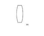
図2は、図1に示した第2レンズ300の第1例を示す図である。本図に示す例において、第2レンズ300は、両凸レンズである。この場合、第2レンズ300は、第2レンズ300に入射する光を集光させることができる。 FIG. 2 is a diagram showing a first example of the
図3は、図1に示した第2レンズ300の第2例を示す図である。本図に示す例において、第2レンズ300は、両凹レンズである。この場合、第2レンズ300は、第2レンズ300に入射する光を集光させることができる。 FIG. 3 is a diagram illustrating a second example of the
図4は、第1可動反射部102の詳細構造の一例を示す平面図である。第1可動反射部102は、可動電極120、枠体110、保持部材130、及び2つの第1固定電極140を備えている。保持部材130は、可動電極120を枠体110に取り付けており、かつ可動電極120の回転軸となる。2つの第1固定電極140は、可動電極120を介して互いに対向しており、可動電極120の回転軸と交わる方向に並んでいる。 FIG. 4 is a plan view showing an example of a detailed structure of the first movable reflecting
可動電極120の平面形状は矩形であるが、第1固定電極140と対向する辺(図4においてY方向に伸びている辺)は、櫛歯形状となっている。枠体110は、可動電極120の4辺のうち第1固定電極140と対向していない2つの辺(図4においてX方向に伸びている辺)それぞれに対向している。保持部材130は、可動電極120のうち枠体110と対向している2辺それぞれに対して設けられている。詳細には、保持部材130は、可動電極120のうち枠体110と対向している辺の中心に接続している。そして2つの保持部材130を結ぶ線が、可動電極120の回転軸となっている。本実施形態では、枠体110、可動電極120、及び保持部材130は一体的に形成されている。 The planar shape of the
第1固定電極140のうち可動電極120と対向する辺は、櫛歯形状となっており、可動電極120の櫛歯部分とかみ合っている。このため、第1固定電極140と可動電極120は、互いに対向する部分の面積が大きくなり、その結果、可動電極120の駆動力は大きくなる。 The side of the first
また、第1固定電極140は、一部が可動電極120と枠体110の間に伸びている。その伸びている部分の先端は、保持部材130に対向している。 Further, a part of the first
第1可動反射部102の可動電極120は、例えば上面が鏡面になっている。この鏡面は、例えば可動電極120の上面に金属膜(例えばAl膜)を形成することにより、形成されている。そして可動電極120の角度を変えることにより、可動電極120に入射してきた光の反射角を変える。可動電極120の角度は、制御部600によって制御される。 The
なお、第2可動反射部104の詳細構造は、平面視における向きが90°異なっている点を除いて、第1可動反射部102の詳細構造と同様である。 The detailed structure of the second
次に、本実施形態の効果について説明する。本実施形態によれば、光走査装置10は、第1可動反射部102及び第2可動反射部104の他に、第1固定反射部202、第2固定反射部204、及び第3固定反射部206を備えている。そして、第1固定反射部202に入射した光は、第1可動反射部102に向けて反射される。第1可動反射部102は、光の方向を第1の方向に走査する。第1可動反射部102で反射された光は、第2固定反射部204を介して第2可動反射部104に入射する。第2可動反射部104は、光の方向を第2の方向に走査する。第2可動反射部104で反射された光は、第3固定反射部206を介して光走査装置10の外部に出射する。 Next, the effect of this embodiment will be described. According to the present embodiment, the
このため、光走査装置10から出射される光の方向を、光走査装置10に入射される光の向きにあわせることができる。すなわち光走査装置10から出射される光の光軸は、光走査装置10に入射される光の光軸と同一の向きを有している。また、第2固定反射部204に対する第1固定反射部202及び第3固定反射部206の角度θ1、θ2を大きくしなくても良いため、光走査装置10の厚さtを薄くできる。For this reason, the direction of the light emitted from the
また、可動反射部として、第1可動反射部102及び第2可動反射部104の2つを用いている。このため、一つの可動反射部に、互いに直交する2つの回転軸を持たせる必要がない。従って、光走査装置10の径方向の寸法は、回転軸が2つではなく1つであるため、そのぶん小さくすることができる。また、光走査装置10の構造がシンプルになるので、製造コストを抑制できる。 In addition, two movable reflective portions, the first movable
さらに、第2レンズ300は、第3固定反射部206からの反射光の光軸に沿って移動可能となっている。そして集光スポット500の位置は、第2レンズ300の焦点の位置によって制御される。このため、第2レンズ300を移動させることで、第1レンズ400から出射される光の光軸に沿って集光スポット500の位置を移動させることができる。 Further, the
図5は、図1の第1の変形例を示す図である。本図に示す例では、光学部材200は、基板100に対向する面に、凹部を備えている。そして、この凹部の底面が第2固定反射部204となっている。そして、光学部材200の基板100に対向する面のうち、この凹部よりも光入射側に位置する領域に第1固定反射部202が設けられており、また、この凹部よりも光出射側に位置する領域に第3固定反射部206が設けられている。なお、この凹部の内側面にも、第1固定反射部202等と同じ金属膜が蒸着されていてもよい。 FIG. 5 is a diagram showing a first modification of FIG. In the example shown in this figure, the
そして、第2固定反射部204の高さHは、第1固定反射部202のうち入射光が当たる部分よりも高くなっており、また、第3固定反射部206のうち入射光が当たる部分よりも高くなっている。 The height H of the second fixed reflecting
本変形例においても、本実施形態と同様の効果が得られる。さらに、本変形例によれば、第2固定反射部204の高さHは、第1固定反射部202の高さhよりも大きくなっている。従って、第1可動反射部102及び第2可動反射部104を光学部材200に近づけても、第1可動反射部102と第2可動反射部104の間の光路を長くすることができる。従って、光走査装置10の厚さ(または径)tを小さくすることができる。 Also in this modification, the same effect as this embodiment is acquired. Furthermore, according to the present modification, the height H of the second
図6は、図1の第2の変形例を示す図である。本図に示す例においては、光学部材200は、第1固定反射部202と第3固定反射部206の間に透光面208を備えている。第2固定反射部204は、透光面208とは逆側に位置し、透光面208を介して光学部材200の内部に入射した入射光を反射する。この場合、第2固定反射部204は、第1固定反射部202および第3固定反射部206よりも、基板100から離れている。基板100を基準としたときの第2固定反射部204の高さGは、第1固定反射部202のうち入射光が当たる部分よりも高くなっており、また、第3固定反射部206のうち入射光が当たる部分よりも高くなっている。 FIG. 6 is a diagram showing a second modification of FIG. In the example shown in the drawing, the
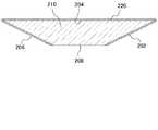
図7は、図6に示した光学部材200の断面図である。光学部材200は、ベース部材210及び反射層220有している。ベース部材210はガラスや樹脂などの透光性の材料を用いて形成されており、第1固定反射部202となる面、第2固定反射部204となる面、及び第3固定反射部206となる面、及び透光面208を有している。反射層220は、ベース部材210のうち第1固定反射部202となる面、第2固定反射部204となる面、及び第3固定反射部206となる面の上に形成されている。反射層220は、光を反射する材料、例えばAlなどの金属によって形成されている。なお、反射層220は、ベース部材210のうち透光面208には形成されていない。 FIG. 7 is a cross-sectional view of the
また、光学部材200は、底面が台形の四角柱を横にした形状を有している。そして、この台形の上底(互いに平行な2辺のうち相対的に短い辺)に相当する面が透光面208になっており、下底(互いに平行な2辺のうち相対的に長い辺)に相当する面が透光面208になっている。また台形の脚に相当する2つの面が、第1固定反射部202及び第3固定反射部206になっている。 In addition, the
図8は、図7に示した光学部材200の製造方法の一例を示す図である。まず、本図(a)に示すように、三角柱のベース部材210を準備する。次いで、本図(b)に示すように、ベース部材210の外面の全面に、反射層220を、例えば蒸着法やスパッタリング法を用いて形成する。次いで、本図(c)に示すように、ベース部材210のうち、第1固定反射部202となる面及び第3固定反射部206となる面とが交わっている辺を研磨する。この研磨により、透光面208が形成される。このように、光学部材200を図3に示した構造にすると、光学部材200を容易に形成することができる。 FIG. 8 is a diagram showing an example of a method for manufacturing the
本変形例においても、本実施形態と同様の効果が得られる。さらに、本変形例によれば、第2固定反射部204までの高さG(図6参照)は、第1固定反射部202の高さh(図6参照)よりも大きくなっている。従って、第1可動反射部102及び第2可動反射部104を光学部材200に近づけても、第1可動反射部102と第2可動反射部104の間の光路を長くすることができる。従って、光走査装置10の厚さ(または径)tを小さくすることができる。 Also in this modification, the same effect as this embodiment is acquired. Furthermore, according to the present modification, the height G (see FIG. 6) to the second fixed reflecting
(第2の実施形態)
図9は、第2の実施形態に係る光走査装置10の構成を示す図であり、第1の実施形態の図1に対応する。本実施形態に係る光走査装置10は、以下の点を除いて、第1の実施形態に係る光走査装置10と同様の構成である。(Second Embodiment)
FIG. 9 is a diagram illustrating a configuration of the
本図に示す例において、第2レンズ300は、調節部304によって焦点距離が可変である。これにより、第2レンズ300の焦点は、第3固定反射部206で反射された入射光の光軸方向に沿って移動可能となる。これにより、集光スポット500の位置を制御することができる。なお、第2レンズ300の形状は、例えば、両凸レンズ(図2)としてもよいし、又は両凹部レンズ(図3)としてもよい。 In the example shown in the drawing, the focal length of the
第2レンズ300の焦点距離は、例えば、第2レンズ300の曲率を変化させることで調節する。より具体的には、例えば、第2レンズ300は、光透過性流動体(例えば、透明な液体又は透明なゲル)を備え、さらにこの光透過性流動体を覆う光透過性弾性膜(例えば、透明な樹脂)を備えている。この場合、光透過性流動体の圧力を調節することで、光透過性弾性膜の曲率(つまり、第2レンズ300の表面の曲率)を調節ことができる。他の例として、第2レンズ300の焦点距離は、電気光学効果を用いて調節する。より具体的には、例えば、第2レンズ300は、誘電体結晶を備えている。この場合、誘電体結晶に発生させる電界によって、第2レンズ300の焦点距離を調節することができる。 The focal length of the
本実施形態においても、第1の実施形態と同様の効果を得ることができる。 Also in this embodiment, the same effect as that of the first embodiment can be obtained.
(第3の実施形態)
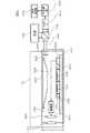
図10は、第3の実施形態に係る内視鏡装置40の構成を示す図である。本実施形態に係る内視鏡装置40は、共焦点光学系の内視鏡装置であり、光走査装置10、光源420、コリメートレンズ422、ダイクロイックミラー430、光ファイバー440、光検出部450、AD変換部460、及び画像処理部470を備えている。本実施形態に係る光走査装置10は、第1の実施形態又は第2の実施形態に係る光走査装置10と同様の構成である。本図に示す例では、光走査装置10は、第1の実施形態に係る光走査装置10と同様の構成である。基板100、光学部材200、第2レンズ300、及びコリメートレンズ422は、ケース410の中に収容されている。ケース410は、内視鏡装置40の先端部を構成しており、その先端に第1レンズ400を有している。光源420は、例えばレーザ光源である。(Third embodiment)
FIG. 10 is a diagram illustrating a configuration of an
本実施形態において、光走査装置10は、基板100、光学部材200、第2レンズ300、第1レンズ400、コリメートレンズ422、配線基板610、及び制御部600を有している。基板100、光学部材200、第2レンズ300、第1レンズ400の構造は、第1の実施形態と同様である。制御部600は半導体ベアチップであり、基板100と共に配線基板610上に実装されている。基板100には貫通電極106が設けられている。第1可動反射部102及び第2可動反射部104は、貫通電極106及び配線基板610を介して、制御部600に接続している。さらに、駆動部302は、制御部600に接続している。 In the present embodiment, the
次に、内視鏡装置40の動作について説明する。光源420が生成した光は、ダイクロイックミラー430で反射され、光ファイバー440に入射する。光ファイバー440は、入射した光をコリメートレンズ422に向けて出射する。この光は、コリメートレンズ422を通過し、その後、コリメート光となる。そしてこのコリメート光は、光学部材200の第1固定反射部202に入射する。第1固定反射部202に入射した光は、第1可動反射部102、第2固定反射部204、第2可動反射部104、第3固定反射部206、及び第2レンズ300を介して、第1レンズ400から観察対象に向けて出射する。このとき、制御部600が第1可動反射部102及び第2可動反射部104を制御することにより、観察対象に向けて出射する光の向きが制御される。さらに、制御部600は、駆動部302を制御している。これにより、第2レンズ300の位置が制御される。そしてこの場合、内視鏡装置40から出射される光の光軸に沿って、集光スポット500(図1)の位置が制御される。 Next, the operation of the
観察対象には、予め蛍光体の分子が含浸されている。この蛍光体の分子は、レーザ光で励起されることにより蛍光発光する。この蛍光発光した光は、第1レンズ400及び第2レンズ300を介して第3固定反射部206、第2可動反射部104、第2固定反射部204、第1可動反射部102、及び第1固定反射部202を介して光ファイバー440に入射する。光ファイバー440に入射した光は、ダイクロイックミラー430を透過して光検出部450によって電気信号に変換される。この電気信号は、AD変換部460によってデジタル信号に変換される。画像処理部470は、AD変換部460が生成したデジタル信号に基づいて画像データを生成する。 The observation object is impregnated with phosphor molecules in advance. The phosphor molecules emit fluorescence when excited by laser light. The fluorescently emitted light passes through the
本実施形態によれば、光走査装置10は、第1の実施形態又は第2の実施形態と同様の構造を有している。このため、内視鏡装置40から出射される光の光軸を、内視鏡装置40が延伸する方向(すなわちケース410が向いている方向)に合わせることができる。また、ケース410の径rを小さくすることができる。さらに、内視鏡装置40から出射される光の集光スポット500(図1)の位置を、内視鏡装置40から出射される光の光軸に沿って移動させることができる。 According to this embodiment, the
(実施例1)
図11は、実施例1に係る光学系の構成を示す図である。この光学系は、第2レンズ300、第1レンズ400、光源420、及びコリメートレンズ422を備えている。第2レンズ300は、光軸に沿って移動可能である。本図に示す例において、光源420からの光は、コリメートレンズ422、第2レンズ300、及び第1レンズ400をこの順で通過し、その後集光スポット500を生成する。そして本図に示すように、コリメートレンズ422は、第2レンズ300の焦点距離f1の外側に位置している。一方、第1レンズ400は、第2レンズ300の焦点距離f1の内側に位置している。Example 1
FIG. 11 is a diagram illustrating a configuration of an optical system according to the first embodiment. This optical system includes a
本実施例に係る光学系の具体的条件は、次のとおりとした。
コリメートレンズ422からのコリメート光のビーム径:φ350μm
第2レンズ300の有効径:φ2.0mm
第1レンズ400の有効径:φ2mm
第1レンズ400の焦点距離f2:0.7mmSpecific conditions of the optical system according to the present example were as follows.
Beam diameter of collimated light from collimating lens 422: φ350 μm
Effective diameter of the second lens 300: φ2.0 mm
Effective diameter of the first lens 400: φ2 mm
Focal length f2 of the first lens 400: 0.7 mm
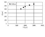
図12は、第2レンズ300と第1レンズ400の間隔d(図11)と第1レンズ400と集光スポット500の間隔X(図11)の関係を示す図である。本図に示す例では、第2レンズ300の焦点距離f1(図11)は、一定(2.5mm)とした。本図に示すように、間隔dを大きくすると、間隔Xは小さくなった。言い換えると、第2レンズ300を第1レンズ400から離れる方向に移動させると、集光スポット500は第1レンズ400に近づくようになった。このように、本実施例によれば、第2レンズ300を移動させることで、集光スポット500の位置を制御することができた。 FIG. 12 is a diagram showing the relationship between the distance d (FIG. 11) between the
(実施例2)
図13は、実施例2に係る光学系の構成を示す図であり、実施例1の図11に対応する。この光学系は、第2レンズ300の焦点距離が可変である点を除いて、実施例1に係る光学系と同様の構成である。(Example 2)
FIG. 13 is a diagram illustrating a configuration of an optical system according to the second embodiment, and corresponds to FIG. 11 of the first embodiment. This optical system has the same configuration as the optical system according to Example 1 except that the focal length of the
図14は、第2レンズ300の焦点距離f1(図13)と第1レンズ400と集光スポット500の間隔X(図13)の関係を示す図である。本図に示す例では、第2レンズ300と第1レンズ400の間隔d(図13)は、一定(500μm)とした。本図に示すように、焦点距離f1を大きくすると、間隔Xは大きくなった。このように、本実施例によれば、第2レンズ300の焦点距離を変化させることで、集光スポット500の位置を制御することができた。 FIG. 14 is a diagram showing the relationship between the focal length f1 (FIG. 13) of the
以上、図面を参照して本発明の実施形態について述べたが、これらは本発明の例示であり、上記以外の様々な構成を採用することもできる。 As mentioned above, although embodiment of this invention was described with reference to drawings, these are the illustrations of this invention, Various structures other than the above are also employable.
10 光走査装置
40 内視鏡装置
100 基板
102 第1可動反射部
104 第2可動反射部
106 貫通電極
110 枠体
120 可動電極
130 保持部材
140 第1固定電極
200 光学部材
202 第1固定反射部
204 第2固定反射部
206 第3固定反射部
208 透光面
210 ベース部材
220 反射層
300 第2レンズ
302 駆動部
304 調節部
400 第1レンズ
410 ケース
420 光源
422 コリメートレンズ
430 ダイクロイックミラー
440 光ファイバー
450 光検出部
460 AD変換部
470 画像処理部
500 集光スポット
600 制御部
610 配線基板DESCRIPTION OF
Claims (5)
Translated fromJapanese反射面が回転可能であり、回転軸が前記第1可動反射部の回転軸と交わる方向を向いており、かつ平面視で前記第1可動反射部と並んで配置されている第2可動反射部と、
平面視で前記第1可動反射部を介して前記第2可動反射部とは逆側に位置し、かつ入射光を前記第1可動反射部に向けて反射する第1固定反射部と、
平面視で前記第1可動反射部と前記第2可動反射部の間に配置されており、前記第1可動反射部で反射された前記入射光を前記第2可動反射部に向けて反射する第2固定反射部と、
平面視で前記第2可動反射部を介して前記第1可動反射部とは逆側に配置されており、前記第2可動反射部で反射された前記入射光を前記第2可動反射部から離れる方向に反射する第3固定反射部と、
平面視で前記第3固定反射部を介して前記第2可動反射部とは逆側に配置されており、前記第3固定反射部で反射された前記入射光を集光する第1レンズと、
平面視で前記第3固定反射部と前記第1レンズの間に配置されており、前記第3固定反射部で反射された前記入射光が入射し、かつ前記第3固定反射部で反射された前記入射光の光軸に沿って焦点が移動可能である第2レンズと、
を備える光走査装置。A first movable reflecting portion whose reflecting surface is rotatable;
A second movable reflector that has a reflecting surface that is rotatable, a rotation axis that faces the rotation axis of the first movable reflector, and that is arranged side by side with the first movable reflector in plan view When,
A first fixed reflector that is located on the opposite side of the second movable reflector through the first movable reflector in plan view and reflects incident light toward the first movable reflector;
The first movable reflecting portion is disposed between the first movable reflecting portion and the second movable reflecting portion in a plan view, and reflects the incident light reflected by the first movable reflecting portion toward the second movable reflecting portion. 2 fixed reflectors;
It is arranged on the opposite side to the first movable reflective part via the second movable reflective part in plan view, and separates the incident light reflected by the second movable reflective part from the second movable reflective part. A third fixed reflector that reflects in the direction;
A first lens that condenses the incident light reflected by the third fixed reflector, disposed on the opposite side of the second movable reflector via the third fixed reflector in plan view;
Arranged between the third fixed reflecting portion and the first lens in plan view, the incident light reflected by the third fixed reflecting portion is incident and reflected by the third fixed reflecting portion. A second lens whose focal point is movable along the optical axis of the incident light;
An optical scanning device comprising:
前記第2レンズは、前記第3固定反射部で反射された前記入射光の光軸に沿って移動可能である光走査装置。The optical scanning device according to claim 1,
The optical scanning device, wherein the second lens is movable along the optical axis of the incident light reflected by the third fixed reflector.
前記第2レンズは、焦点距離が可変である光走査装置。The optical scanning device according to claim 1,
The second lens is an optical scanning device having a variable focal length.
前記第2レンズは、両凸レンズであり、又は両凹レンズである光走査装置。In the optical scanning device according to any one of claims 1 to 3,
The optical scanning device, wherein the second lens is a biconvex lens or a biconcave lens.
前記光源から入射された光を走査するとともに、前記光が観察対象で反射した反射光を取り出す光走査装置と、
を備え、
前記光走査装置は、
反射面が回転可能である第1可動反射部と、
反射面が回転可能であり、回転軸が前記第1可動反射部の回転軸と交わる方向を向いており、かつ平面視で前記第1可動反射部と並んで配置されている第2可動反射部と、
平面視で前記第1可動反射部を介して前記第2可動反射部とは逆側に位置し、かつ入射光を前記第1可動反射部に向けて反射する第1固定反射部と、
平面視で前記第1可動反射部と前記第2可動反射部の間に配置されており、前記第1可動反射部で反射された前記入射光を前記第2可動反射部に向けて反射する第2固定反射部と、
平面視で前記第2可動反射部を介して前記第1可動反射部とは逆側に配置されており、前記第2可動反射部で反射された前記入射光を前記第2可動反射部から離れる方向に反射する第3固定反射部と、
平面視で前記第3固定反射部を介して前記第2可動反射部とは逆側に配置されており、前記第3固定反射部で反射された前記入射光を集光する第1レンズと、
平面視で前記第3固定反射部と前記第1レンズの間に配置されており、前記第3固定反射部で反射された前記入射光が入射し、かつ前記第3固定反射部で反射された前記入射光の光軸に沿って焦点が移動可能である第2レンズと、
を備える内視鏡装置。A light source;
An optical scanning device that scans the light incident from the light source and extracts reflected light reflected by the observation target;
With
The optical scanning device includes:
A first movable reflecting portion whose reflecting surface is rotatable;
A second movable reflector that has a reflecting surface that is rotatable, a rotation axis that faces the rotation axis of the first movable reflector, and that is arranged side by side with the first movable reflector in plan view When,
A first fixed reflector that is located on the opposite side of the second movable reflector through the first movable reflector in plan view and reflects incident light toward the first movable reflector;
The first movable reflecting portion is disposed between the first movable reflecting portion and the second movable reflecting portion in a plan view, and reflects the incident light reflected by the first movable reflecting portion toward the second movable reflecting portion. 2 fixed reflectors;
It is arranged on the opposite side to the first movable reflective part via the second movable reflective part in plan view, and separates the incident light reflected by the second movable reflective part from the second movable reflective part. A third fixed reflector that reflects in the direction;
A first lens that condenses the incident light reflected by the third fixed reflector, disposed on the opposite side of the second movable reflector via the third fixed reflector in plan view;
Arranged between the third fixed reflecting portion and the first lens in plan view, the incident light reflected by the third fixed reflecting portion is incident and reflected by the third fixed reflecting portion. A second lens whose focal point is movable along the optical axis of the incident light;
An endoscope apparatus comprising:
Priority Applications (1)
| Application Number | Priority Date | Filing Date | Title |
|---|---|---|---|
| JP2015037286AJP2016161595A (en) | 2015-02-26 | 2015-02-26 | Optical scanning device and endoscope device |
Applications Claiming Priority (1)
| Application Number | Priority Date | Filing Date | Title |
|---|---|---|---|
| JP2015037286AJP2016161595A (en) | 2015-02-26 | 2015-02-26 | Optical scanning device and endoscope device |
Publications (1)
| Publication Number | Publication Date |
|---|---|
| JP2016161595Atrue JP2016161595A (en) | 2016-09-05 |
Family
ID=56846898
Family Applications (1)
| Application Number | Title | Priority Date | Filing Date |
|---|---|---|---|
| JP2015037286APendingJP2016161595A (en) | 2015-02-26 | 2015-02-26 | Optical scanning device and endoscope device |
Country Status (1)
| Country | Link |
|---|---|
| JP (1) | JP2016161595A (en) |
Cited By (1)
| Publication number | Priority date | Publication date | Assignee | Title |
|---|---|---|---|---|
| EP4498145A1 (en)* | 2023-07-27 | 2025-01-29 | Fraunhofer-Gesellschaft zur Förderung der angewandten Forschung e.V. | Reflective optical system with adjustable effective focal length and optical assembly |
Citations (5)
| Publication number | Priority date | Publication date | Assignee | Title |
|---|---|---|---|---|
| JPH10118007A (en)* | 1996-10-18 | 1998-05-12 | Olympus Optical Co Ltd | Endoscope |
| JP2000126115A (en)* | 1998-10-28 | 2000-05-09 | Olympus Optical Co Ltd | Optical scanning probe device |
| JP2008504557A (en)* | 2004-06-28 | 2008-02-14 | ユニヴァーシティ オブ ワシントン | Multi-mode optical imaging method and optical fiber scanner thereof |
| US20100168586A1 (en)* | 2007-06-29 | 2010-07-01 | The Trustees Of Columbia University In The City Of New York | Optical imaging or spectroscopy systems and methods |
| JP2014021187A (en)* | 2012-07-13 | 2014-02-03 | Kyushu Univ | Optical scanner and endoscope device |
- 2015
- 2015-02-26JPJP2015037286Apatent/JP2016161595A/enactivePending
Patent Citations (5)
| Publication number | Priority date | Publication date | Assignee | Title |
|---|---|---|---|---|
| JPH10118007A (en)* | 1996-10-18 | 1998-05-12 | Olympus Optical Co Ltd | Endoscope |
| JP2000126115A (en)* | 1998-10-28 | 2000-05-09 | Olympus Optical Co Ltd | Optical scanning probe device |
| JP2008504557A (en)* | 2004-06-28 | 2008-02-14 | ユニヴァーシティ オブ ワシントン | Multi-mode optical imaging method and optical fiber scanner thereof |
| US20100168586A1 (en)* | 2007-06-29 | 2010-07-01 | The Trustees Of Columbia University In The City Of New York | Optical imaging or spectroscopy systems and methods |
| JP2014021187A (en)* | 2012-07-13 | 2014-02-03 | Kyushu Univ | Optical scanner and endoscope device |
Cited By (1)
| Publication number | Priority date | Publication date | Assignee | Title |
|---|---|---|---|---|
| EP4498145A1 (en)* | 2023-07-27 | 2025-01-29 | Fraunhofer-Gesellschaft zur Förderung der angewandten Forschung e.V. | Reflective optical system with adjustable effective focal length and optical assembly |
Similar Documents
| Publication | Publication Date | Title |
|---|---|---|
| US9383574B2 (en) | Translation mirror based beam steering mechanism with ultrahigh frequency response and high sensitivity | |
| US7190499B2 (en) | Laser scanning unit | |
| JP2004070278A (en) | Compact optical unit | |
| JP2016148829A (en) | Observation device | |
| JP2005049742A (en) | Variable optical attenuator | |
| JP6146965B2 (en) | Optical scanning apparatus and endoscope apparatus | |
| CN103309030A (en) | Focus position changing apparatus and confocal optical apparatus using the same | |
| JP6153460B2 (en) | Optical scanning apparatus and endoscope apparatus | |
| US20200088979A1 (en) | Optical apparatus | |
| JP2016161595A (en) | Optical scanning device and endoscope device | |
| JP2013120274A (en) | Confocal optical scanner and confocal microscope | |
| JP6137914B2 (en) | Optical scanning apparatus and endoscope apparatus | |
| JP6274845B2 (en) | Optical device | |
| JP4246981B2 (en) | Laser processing equipment | |
| WO2023053840A1 (en) | Optical scanning device | |
| JP2010044208A (en) | Confocal optical device | |
| JP6251564B2 (en) | Optical scanning apparatus and endoscope apparatus | |
| JP7221745B2 (en) | Optical scanning device, light source device | |
| JP2016200640A (en) | Optical scanning apparatus and endoscope apparatus | |
| JP6347980B2 (en) | Optical scanning device | |
| Piyawattanametha et al. | MEMS based dual-axes confocal reflectance handheld microscope for in vivo imaging | |
| US12320629B2 (en) | Thin film characteristic measuring apparatus | |
| JPH0915520A (en) | Optical scanning optical device | |
| JPH07209599A (en) | Optical scanning device and polygon mirror | |
| JP2015022287A (en) | Optical scanning device |
Legal Events
| Date | Code | Title | Description |
|---|---|---|---|
| A521 | Request for written amendment filed | Free format text:JAPANESE INTERMEDIATE CODE: A523 Effective date:20171207 | |
| A521 | Request for written amendment filed | Free format text:JAPANESE INTERMEDIATE CODE: A821 Effective date:20171207 | |
| A621 | Written request for application examination | Free format text:JAPANESE INTERMEDIATE CODE: A621 Effective date:20180215 | |
| A521 | Request for written amendment filed | Free format text:JAPANESE INTERMEDIATE CODE: A821 Effective date:20180216 | |
| A131 | Notification of reasons for refusal | Free format text:JAPANESE INTERMEDIATE CODE: A131 Effective date:20181204 | |
| A977 | Report on retrieval | Free format text:JAPANESE INTERMEDIATE CODE: A971007 Effective date:20181130 | |
| A02 | Decision of refusal | Free format text:JAPANESE INTERMEDIATE CODE: A02 Effective date:20190604 |