JP2016160981A - Pressure container - Google Patents
Pressure containerDownload PDFInfo
- Publication number
- JP2016160981A JP2016160981AJP2015038319AJP2015038319AJP2016160981AJP 2016160981 AJP2016160981 AJP 2016160981AJP 2015038319 AJP2015038319 AJP 2015038319AJP 2015038319 AJP2015038319 AJP 2015038319AJP 2016160981 AJP2016160981 AJP 2016160981A
- Authority
- JP
- Japan
- Prior art keywords
- cylindrical
- valve
- pressure vessel
- base
- liner
- Prior art date
- Legal status (The legal status is an assumption and is not a legal conclusion. Google has not performed a legal analysis and makes no representation as to the accuracy of the status listed.)
- Pending
Links
- 230000002093peripheral effectEffects0.000claimsabstractdescription46
- 239000010410layerSubstances0.000claimsdescription39
- 230000003014reinforcing effectEffects0.000claimsdescription39
- 229920005989resinPolymers0.000claimsdescription23
- 239000011347resinSubstances0.000claimsdescription23
- 239000002184metalSubstances0.000claimsdescription12
- 239000012790adhesive layerSubstances0.000claimsdescription9
- 238000007789sealingMethods0.000abstractdescription24
- 230000003247decreasing effectEffects0.000abstract1
- 239000000835fiberSubstances0.000description15
- 239000012530fluidSubstances0.000description13
- 230000004888barrier functionEffects0.000description8
- VNWKTOKETHGBQD-UHFFFAOYSA-NmethaneChemical compoundCVNWKTOKETHGBQD-UHFFFAOYSA-N0.000description7
- 230000007423decreaseEffects0.000description6
- 229920003002synthetic resinPolymers0.000description5
- 239000000057synthetic resinSubstances0.000description5
- 230000000694effectsEffects0.000description4
- 239000003345natural gasSubstances0.000description3
- UFHFLCQGNIYNRP-UHFFFAOYSA-NHydrogenChemical compound[H][H]UFHFLCQGNIYNRP-UHFFFAOYSA-N0.000description2
- 239000004918carbon fiber reinforced polymerSubstances0.000description2
- 239000007789gasSubstances0.000description2
- 230000002787reinforcementEffects0.000description2
- 229920001187thermosetting polymerPolymers0.000description2
- 229920000049Carbon (fiber)Polymers0.000description1
- 238000000071blow mouldingMethods0.000description1
- 239000004917carbon fiberSubstances0.000description1
- 230000001747exhibiting effectEffects0.000description1
- 239000011152fibreglassSubstances0.000description1
- 238000009730filament windingMethods0.000description1
- 239000000446fuelSubstances0.000description1
- 239000003365glass fiberSubstances0.000description1
- 239000007788liquidSubstances0.000description1
- 238000000034methodMethods0.000description1
- 239000002356single layerSubstances0.000description1
- 238000003466weldingMethods0.000description1
Images


Landscapes
- Filling Or Discharging Of Gas Storage Vessels (AREA)
Abstract
Description
Translated fromJapanese本発明は、圧力容器に関するものである。 The present invention relates to a pressure vessel.
特許文献1には、胴部の両端に一対のドーム部が連なるように成形されたライナーと、ドーム部の頂部に形成した筒状突出部に外嵌される筒状の口金と、口金内に取り付けられるバルブとを備えた圧力容器が開示されている。バルブは筒状突出部に内嵌されるが、バルブの外周と筒状突出部の内周との界面は、圧力容器内の流体のリーク経路となり得る。そこで、筒状突出部の外周と口金の内周との間に第1シール部材を設けるともとに、口金とバルブとの間に第2シール部材を設けている。 In Patent Document 1, a liner formed so that a pair of dome parts are connected to both ends of a body part, a cylindrical base fitted on a cylindrical projecting part formed on the top of the dome part, and a base A pressure vessel with an attached valve is disclosed. Although the valve is fitted into the cylindrical protrusion, the interface between the outer periphery of the valve and the inner periphery of the cylindrical protrusion can be a fluid leakage path in the pressure vessel. Therefore, a first seal member is provided between the outer periphery of the cylindrical protrusion and the inner periphery of the base, and a second seal member is provided between the base and the valve.
合成樹脂製のライナーは、圧力容器の内圧を受けてへたる虞がある。筒状突出部がへたりを生じると、筒状突出部の外周と口金の内周との隙間が拡がって、第1シール部材によるシール性能の低下が懸念される。そこで、ライナーのヘタリに起因するシール性能の低下を回避する手段として、筒状突出部にはリング状の補強部材が取り付けられている。 The synthetic resin liner may sag due to the internal pressure of the pressure vessel. If the cylindrical projecting portion sags, the gap between the outer periphery of the cylindrical projecting portion and the inner periphery of the base expands, and there is a concern that the sealing performance may be deteriorated by the first seal member. Therefore, a ring-shaped reinforcing member is attached to the cylindrical protrusion as a means for avoiding a decrease in sealing performance due to the settling of the liner.
上記従来の圧力容器は、ライナーのヘタリに起因するシール性能の低下を回避する手段として、ライナーとは別体の補強部材が用いられているので、部品点数が多くなるという問題がある。 The conventional pressure vessel has a problem that the number of parts is increased because a reinforcing member separate from the liner is used as a means for avoiding a decrease in sealing performance due to liner settling.
本発明は上記のような事情に基づいて完成されたものであって、部品点数を増やすことなく、ライナーのヘタリに起因するシール性能の低下を防止することを目的とする。 The present invention has been completed based on the above-described circumstances, and an object of the present invention is to prevent a decrease in sealing performance due to liner settling without increasing the number of parts.
本発明の圧力容器は、
胴部の端部にドーム部が連なるように成形されたライナーと、
前記ドーム部の頂部に外向きに突出するように形成された筒状突出部と、
前記筒状突出部に外嵌された筒状の口金と、
前記口金内に取り付けられて、前記筒状突出部に内嵌されたバルブと、
前記筒状突出部の周面に密着するように設けたシール部材とを備え、
前記筒状突出部は、前記ドーム部に連なって外向きに突出した第1筒部と、前記第1筒部の突出端縁から内周側へ折り返すように延出して前記バルブに外嵌された第2筒部とを有する二重壁構造であるところに特徴を有する。The pressure vessel of the present invention is
A liner formed so that the dome portion is continuous with the end portion of the trunk portion;
A cylindrical protrusion formed to protrude outward at the top of the dome,
A cylindrical base fitted on the cylindrical protrusion, and
A valve mounted in the base and fitted in the cylindrical protrusion;
A seal member provided so as to be in close contact with the peripheral surface of the cylindrical protrusion,
The tubular projecting portion extends outwardly from the projecting end edge of the first tubular portion and extends outwardly from the projecting end edge of the first tubular portion, and is externally fitted to the valve. In addition, the present invention is characterized in that it has a double wall structure having a second cylindrical portion.
第1筒部の内周と第2筒部の外周にはライナー内の圧力が作用する。これにより、筒状突出部にへたりが生じても、筒状突出部の外周が口金の内周側へ押圧されるとともに、筒状突出部の内周がバルブの外周側へ押圧される。したがって、部品点数を増やさなくても、筒状突出部の周面に設けたシール部材によるシール性能が低下する虞はない。 The pressure in the liner acts on the inner periphery of the first tube portion and the outer periphery of the second tube portion. Thereby, even if a sag occurs in the cylindrical protruding portion, the outer periphery of the cylindrical protruding portion is pressed toward the inner peripheral side of the base, and the inner periphery of the cylindrical protruding portion is pressed toward the outer peripheral side of the valve. Therefore, even if the number of parts is not increased, there is no possibility that the sealing performance by the sealing member provided on the peripheral surface of the cylindrical projecting portion is lowered.
(a)本発明の圧力容器は、前記シール部材が、前記第2筒部の内周と前記バルブの外周との間に配されていてもよい。この構成によれば、第1筒部(筒状突出部)の外周と口金の内周との間、及び口金とバルブとの間にシール手段を設けずに済む。 (A) In the pressure vessel according to the present invention, the seal member may be disposed between an inner periphery of the second cylindrical portion and an outer periphery of the valve. According to this configuration, it is not necessary to provide sealing means between the outer periphery of the first tube portion (tubular protruding portion) and the inner periphery of the base, and between the base and the valve.
(b)本発明の圧力容器は、前記第1筒部の内周と前記第2筒部の外周との間に筒状の補強部材が設けられていてもよい。この構成によれば、第2筒部を第1筒部の内周側へ折り返す際に、補強部材が第1筒部の内周側への不正な変形を防止する。 (B) In the pressure vessel of the present invention, a cylindrical reinforcing member may be provided between the inner periphery of the first tube portion and the outer periphery of the second tube portion. According to this configuration, when the second tube portion is folded back to the inner peripheral side of the first tube portion, the reinforcing member prevents unauthorized deformation to the inner peripheral side of the first tube portion.
(c)本発明の圧力容器は、(b)において、前記補強部材が金属製であってもよい。この構成によれば、温度上昇によって筒状突出部の剛性が低下したときには、圧力容器の内圧だけでなく、金属製の補強部材の熱膨張によっても、筒状突出部の外周が口金の内周側へ押圧されるとともに、筒状突出部の内周がバルブの外周側へ押圧される。 (C) In the pressure vessel of the present invention, the reinforcing member in (b) may be made of metal. According to this configuration, when the rigidity of the cylindrical protrusion decreases due to a temperature rise, not only the internal pressure of the pressure vessel but also the thermal expansion of the metal reinforcing member causes the outer periphery of the cylindrical protrusion to be the inner periphery of the base. And the inner periphery of the cylindrical protrusion is pressed toward the outer periphery of the valve.
(d)本発明の圧力容器は、前記ライナーが複数の樹脂層を積層した多層構造であり、前記樹脂層間の界面が前記第2筒部の延出端面に臨んでおり、前記第2筒部の延出端面が接着層で覆われていてもよい。この構成によれば、樹脂層間の界面に圧力容器の内圧が作用することを防止できる。 (D) In the pressure vessel of the present invention, the liner has a multilayer structure in which a plurality of resin layers are laminated, and an interface between the resin layers faces an extended end surface of the second cylinder part, and the second cylinder part The extended end face of the film may be covered with an adhesive layer. According to this structure, it can prevent that the internal pressure of a pressure vessel acts on the interface between resin layers.
<実施例1>
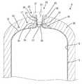
以下、本発明を具体化した実施例1を図1〜図2を参照して説明する。本実施例1の圧力容器Aは、合成樹脂製のライナー10と、口金23と、繊維強化樹脂層28と、バルブ30とを備えて構成されている。圧力容器Aは、燃料電池自動車や天然ガス自動車に搭載され、高圧の水素ガスや天然ガスの充填容器として用いられるものであるから、流体の漏出を防止するためのシール機能には、高い信頼性が求められる。<Example 1>
Embodiment 1 of the present invention will be described below with reference to FIGS. The pressure vessel A according to the first embodiment includes a
<ライナー10>
ライナー10は、径寸法が全長に亘ってほぼ一定の円筒状をなす胴部11と、胴部11の軸線方向両端縁に連なる一対のドーム部12とを備えた単一部品である。ライナー10の内部は、流体(水素ガスや天然ガス等)を貯留するための貯留空間13となっている。ライナー10は、ブロー成形によって所定形状に成形されている。ライナー10は、その外周側面と内周面との間において外層14(請求項に記載の樹脂層)とバリア層15(請求項に記載の樹脂層)と内層16(請求項に記載の樹脂層)を積層した3層構造をなしている。バリア層15は、圧力容器A(貯留空間13)内の流体(ガス)が圧力容器Aの外部へ透過することを阻止する。<
The
一方のドーム部12の頂部17には、胴部11の軸線と同軸の円形をなす筒状突出部18が一体に、且つドーム部12の外方へ突出した形態で形成されている。筒状突出部18の内部空間は、その突出端がライナー10の外部へ開放されている。筒状突出部18は、第1筒部19と第2筒部22とを有する二重壁構造となっている。 On the
第1筒部19は基端側領域20と突出端側領域21とによって構成されている。基端側領域20は、直接ドーム部12に連なっていて、略四半円弧状に湾曲したテーパ状をなし、ドーム部12の外方へ突出している。突出端側領域21は、基端側領域20の突出端縁に滑らかに連なっていて、基端側領域20よりも更に外方へ突出している。つまり、第1筒部19は、その全体がドーム部12から外方へ突出した形態である。突出端側領域21は、胴部11及びドーム部12と同軸状であって、径寸法が軸方向全領域に亘って一定の円筒状をなしている。 The first
第2筒部22は、第1筒部19の突出端縁から内周側へ折り返されるように延出した形態である。第2筒部22は、第1筒部19の突出端側領域21と同様、径寸法が軸方向全領域に亘って一定の円筒状をなしている。第2筒部22の外周面は、第1筒部19の突出端側領域21の内周面に対し、ほぼ密着するように重なっているが、接着はされていない。第2筒部22の延出端は、突出端側領域21の範囲内に位置し、基端側領域20とは非対応となるように位置している。第2筒部22の延出端は貯留空間13内に臨んでいる。そして、第2筒部22と突出端側領域21とが密着している界面Saも、貯留空間13に臨んでいる。 The second
<口金23>
筒状突出部18には、口金23が外嵌されている。口金23は、口金本体部24と、治具受け部25と、大径部26とを一体に形成したものである。口金本体部24は、筒状突出部18と同軸状の円筒形をなしている。口金本体部24の内周には、雌ネジ部27が形成されている。治具受け部25は、口金本体部24の軸線方向両端部のうちライナー10(圧力容器A)の外面側の端部から、径方向外側へフランジ状に張り出した形態であり、外周形状は非円形である。<
A
大径部26は、口金本体部24の他方(貯留空間13に臨む側)の端部から径方向外側へフランジ状に張り出した形態である。大径部26は、筒状突出部18と同軸状の円形をなす。大径部26の外周面は口金本体部24の外周面と滑らかに連なっている。大径部26の内面には第1筒部19の外面が密着しており、大径部26の軸線と交差する端面は、ドーム部12の外面に密着している。 The large-
<繊維強化樹脂層28>
繊維強化樹脂層28は、炭素繊維強化プラスチック(CFRP)、ガラス繊維強化プラスッチック等からなる。繊維強化樹脂層28は、胴部11の軸線を中心として回転するライナー10の外面に、図示しない繊維束(炭素繊維、ガラス繊維、ケプラ繊維等からなる糸状の繊維を束ねたもの)に液状の熱硬化性樹脂を含浸させたもの、又は繊維束に含浸した熱硬化性樹脂を半硬化状態にしたもの(プリプレグ繊維)を巻き付けるフィラメントワインディング法によって形成されている。<Fiber reinforced
The fiber reinforced
繊維強化樹脂層28は、胴部11の外周面の全領域と、ドーム部12の外周面のうち口金23で覆われていない領域と、口金23の口金本体部24の外周面と、口金23の大径部26の外面とを覆い隠すように形成されている。口金23は、大径部26がドーム部12(ライナー10)と繊維強化樹脂層28との間で挟み付けられることにより、ライナー10及び繊維強化樹脂層28と一体化されている。これにより、ライナー10の筒状突出部18の第1筒部19が口金23の内面に密着した状態に保たれる。 The fiber reinforced
<バルブ30>
バルブ30は、圧力容器A(貯留空間13)の内部と外部との間における流体(高圧ガス等)の流動と遮断とを切り替えるものである。バルブ30は、口金23及び筒状突出部18と同軸状のエアシリンダ略円柱形なすバルブ本体部31と、治具嵌合部32と、シール機能部33とを有する単一部品である。バルブ本体部31の外周には、雄ネジ部34が形成されている。治具嵌合部32は、バルブ本体部31の軸線方向両端部のうちライナー10(圧力容器A)の外面側の端部に連なり、バルブ本体部31よりもフランジ状に拡径した形態であり、外周形状は非円形である。<
The
シール機能部33は、バルブ本体部31と同軸状でバルブ本体部31よりも小径の円柱形をなしている。シール機能部33は、バルブ本体部31の他方(貯留空間13に臨む側)の端部から、更に貯留空間13側へ突出した形態である。シール機能部33の外周には、周方向のシール溝35が形成されている。シール溝35には、リング状のシール部材36が取り付けられている。 The
バルブ30は、ライナー10に口金23と繊維強化樹脂層28を一体化させた後に、圧力容器Aの外側から口金23に取り付けられている。取付けの際には、シール機能部33を先に向けてバルブ30を口金本体部24内に挿入し、手作業で雄ネジ部34を雌ネジ部27にねじ込んでいく。そして、最後に、口金23の治具受け部25とバルブ30の治具嵌合部32に治具(図示省略)を嵌合してバルブ30を締め付ける。 The
バルブ30を口金23に取り付けた状態では、シール機能部33が筒状突出部18内に嵌合し、シール部材36が第2筒部22の内周面に密着する。これにより、筒状突出部18(第2筒部22)の内周面とバルブ30(シール機能部33)の外周面との隙間が気密状対にシールされる。また、シール部材36は、筒状突出部18の軸線方向において第1筒部19の内面と第2筒部22の外面との界面Saと対応する位置に配されている。 In a state where the
<実施例1の作用及び効果>
圧力容器A(貯留空間13)内の圧力が高くなると、筒状突出部18とバルブ30との隙間を通る経路での流体のリークが懸念される。しかし、本実施例1の圧力容器Aは、筒状突出部18が第1筒部19と第2筒部22とによる二重壁構造をなしていて、第1筒部19の内周と第2筒部22の外周との界面Saが貯留空間13に臨んでいるので、貯留空間13の内圧が高まると、この界面Sa(つまり、第1筒部19の内周面と第2筒部22の外周面)に流体圧が作用する。このとき、第2筒部22の内周面とバルブ30のシール機能部33の外周面との隙間Sbにも同じ内圧が作用する。<Operation and Effect of Example 1>
When the pressure in the pressure vessel A (reservation space 13) becomes high, there is a concern that fluid leaks in a path that passes through the gap between the
しかし、第2筒部22の内周面の受圧面積よりも第2筒部22の外周面の受圧面積の方が大きいので、受圧面積の相違に起因する差圧により、第2筒部22は径方向内側へ押圧される。これにより、第2筒部22の内周面がシール部材36に対し強く密着してセルフシール機能が発揮されるので、界面Saにおける流体のリークが確実に防止される。 However, since the pressure receiving area of the outer peripheral surface of the second
また、リーク経路のうち第2筒部22の内周とバルブ30の外周との隙間Sbよりも下流側では、経路が二手に分岐する。一方の分岐経路は、第1筒部19の外周と口金23の内周との間の界面Scと、口金23とドーム部12の外面との間の界面Sdと、口金23の外面と繊維強化樹脂層28との界面Seとを順に通る経路である。他方の分岐経路は、口金23の内周面とバルブ30の外周面との隙間Sfを通る経路である。 In addition, on the downstream side of the clearance Sb between the inner circumference of the
しかし、本実施例1では、第2筒状部材22の内周面(筒状突出部18の周面)に密着するようにシール部材36を設け、このシール部材36により、第2筒部22の内周とバルブ30の外周の隙間Sbのリークを遮断している。したがって、シール部材36よりも下流側の分岐経路(即ち、第1筒部19の外周と口金23の内周との界面Sc、及び口金23とバルブ30との隙間Sfにはシール手段を設ける必要がない。 However, in the first embodiment, the sealing
上述のように本実施例1の圧力容器Aは、胴部11の端部にドーム部12が連なるように成形されたライナー10と、ドーム部12の頂部17に外向きに突出するように形成された筒状突出部18と、筒状突出部18に外嵌された筒状の口金23と、口金23内に取り付けられて筒状突出部18に内嵌されたバルブ30と、筒状突出部18の周面に密着するように設けたシール部材36とを備えている。筒状突出部18は、ドーム部12に連なって外向きに突出した第1筒部19と、第1筒部19の突出端縁から内周側へ折り返すように延出してバルブ30に外嵌された第2筒部22とを有する二重壁構造である。 As described above, the pressure vessel A according to the first embodiment is formed so as to protrude outward from the
第1筒部19の基端部内周(基端側領域20)の内周と第2筒部22の外周との界面Saは、ライナー10の内部(貯留空間13)に臨んでいるので、この界面Saにはライナー10内の圧力が作用する。これにより、筒状突出部18にへたりが生じても、筒状突出部18の第1筒部19の外周が口金23の内周側へ押圧されるとともに、筒状突出部18の第2筒部22の内周がバルブ30の外周側へ押圧されてシール部材36に強く密着し、セルフシール機能が発揮される。このセルフシール機能は、貯留空間13の内圧が高ければ高いほどシール性能が高まるので、貯留空間13の内圧上昇に対応するための専用部品を設ける必要がない。したがって、部品点数を増やさなくても、筒状突出部18の周面に設けたシール部材36によるシール性能が低下する虞はない。 The interface Sa between the inner periphery of the base end portion inner periphery (base end side region 20) of the
<実施例2>
次に、本発明を具体化した実施例2を図3を参照して説明する。本実施例2の圧力容器Bは、ライナー40の筒状突出部41を上記実施例1の筒状突出部18とは異なる構成としたものである。その他の構成については上記実施例1と同じであるため、同じ構成については、同一符号を付し、構造、作用及び効果の説明は省略する。<Example 2>
Next, a second embodiment of the present invention will be described with reference to FIG. In the pressure vessel B of the second embodiment, the
本実施例2の圧力容器Bは、金属製の補強部材42を有している。補強部材42は、筒状突出部41と同軸の円筒状をなし、第1筒部19の内周と第2筒部22の外周との間に挟まれるように配されている。補強部材42は、第2筒部22を折り返し成形する前に、第1筒部19の突出端側領域21の内周面に接着や溶着等によって固着(一体化)されている。補強部材42を第1筒部19に固着したことにより、第2筒部22を第1筒部19の内周側へ折り返す際に第1筒部19が内周側へ不正に変形することが、補強部材42によって防止されている。 The pressure vessel B of the second embodiment has a
また、補強部材42には、その軸線方向における貯留空間13側の端縁部から径方向内側へ同心円状に突出した形態の覆い部43が形成されている。覆い部43は、第2筒部22の延出端面を覆うように配されている。 Further, the reinforcing
貯留空間13の内圧が高まった場合には、第2筒部22の延出端面と覆い部43との隙間Sg、補強部材42の内周面と第2筒部22の外周面との隙間Shに流体圧が作用する。ここで、補強部材42は金属製であって第2筒部22よりも剛性が高いので、流体圧により第2筒部22が径方向内側へ押圧され、シール部材36に強く密着する。 When the internal pressure of the
また、補強部材42は、金属製であることによって次のような効果を発揮する。圧力容器Bの温度が上昇して合成樹脂製の筒状突出部18の剛性が低下したときには、圧力容器B(貯留空間13)の内圧だけでなく、金属製の補強部材42の熱膨張によっても、第1筒部19の外周が口金23の内周側へ押圧されるとともに、第2筒部22の内周がバルブ30の外周側へ押圧されてシール部材36に強く密着する。このように、金属製の補強部材42は、シール性能の向上に寄与する。 Moreover, the reinforcing
<実施例3>
次に、本発明を具体化した実施例3を図4を参照して説明する。本実施例3の圧力容器Cは、ライナー50の筒状突出部51を上記実施例2の筒状突出部41とは異なる構成としたものである。その他の構成については上記実施例2と同じであるため、同じ構成については、同一符号を付し、構造、作用及び効果の説明は省略する。<Example 3>
Next, a third embodiment of the present invention will be described with reference to FIG. In the pressure vessel C of the third embodiment, the
本実施例3の圧力容器Cは、金属製の補強部材52と、接着層54とを有している。補強部材52は、筒状突出部51と同軸の円筒状をなし、第1筒部19の内周と第2筒部22の外周との間に挟まれるように配されている。補強部材52は、第2筒部22を折り返し加工する前に、第1筒部19の突出端側領域20の内周面を覆うように位置決めされて保持されている。補強部材52を第1筒部19に沿うように固定したことにより、第2筒部22を第1筒部19の内周側へ折り返す際に第1筒部19が内周側へ不正に変形することが、補強部材52によって防止されている。また、補強部材52には、その軸線方向における貯留空間13側の端縁部から径方向内側へ同心円状に突出した形態の覆い部53が形成されている。 The pressure vessel C of the third embodiment includes a
ライナー50は、外層14とバリア層15と内層16とを積層した多層構造であり、外層14とバリア層15との界面Si、及びバリア層15と内層16との界面Sjが、第2筒部22の延出端面に臨んでいる。そのため、もし第2筒部22の延出端面が、直接、貯留空間13内に臨んでいると、貯留空間13の内圧により上記界面Si,Sjに流体が浸入する虞がある。そこで、本実施例3の圧力容器Cは、第2筒部22の延出端面を接着層54によって気密状に覆っている。これにより、上記の界面Si,Sjに圧力容器C(貯留空間13)の内圧が作用することが防止されている。また、接着層54の外面には、補強部材52の覆い部53が接着されている。これにより、覆い部53と第2筒部22の延出端面との間が、気密状態にシールされている。 The
貯留空間13の内圧が高まった場合には、第1筒部19の内周面と補強部材52の外周面との隙間Skと、この隙間Skを介して補強部材52の内周面と第2筒部22の外周面との隙間Smに流体圧が作用する。ここで、補強部材52は金属製であって第2筒部22よりも剛性が高いので、流体圧により第2筒部22が径方向内側へ押圧され、シール部材36に強く密着する。また、補強部材52は金属製であるから、実施例2と同様、圧力容器Cの温度が上昇して合成樹脂製の筒状突出部51の剛性が低下したときには、シール性能の向上に寄与する。 When the internal pressure of the
<他の実施例>
本発明は上記記述及び図面によって説明した実施例に限定されるものではなく、例えば次のような実施例も本発明の技術的範囲に含まれる。
(1)上記実施例1〜3では、シール部材を第2筒部の内周とバルブの外周との間に設けたが、第2筒部の内周とバルブの外周との間にはシール手段を設けず、第1筒部の外周と口金の内周との間にシール部材を配し、口金とバルブとの間に別のシール部材を設けてもよい。
(2)上記実施例1〜3では、ライナーが複数の樹脂層を積層した多層構造であるが、これに限らず、ライナーは単層構造であってもよい。
(3)上記実施例2では、補強部材に、第2筒部の延出端面を覆う覆い部を形成したが、補強部材は、第2筒部の延出端面を覆う覆い部が形成されていないものであってもよい。
(4)上記実施例3では、接着層に覆い部が重なる形態としたが、接着層に覆い部が重ならない形態としてもよい。
(5)上記実施例3では、接着層を覆う覆い部が補強部材に一体形成されているが、覆い部は、補強部材とは別体の部品であってもよい。
(6)上記実施例3では、補強部材を設け、この補強部材に覆い部を形成したが、補強部材を設けず、覆い部を単独の部品として設けてもよい。
(7)上記実施例2,3では、補強部材を金属製としたが、補強部材は合成樹脂製であってもよい。<Other embodiments>
The present invention is not limited to the embodiments described with reference to the above description and drawings. For example, the following embodiments are also included in the technical scope of the present invention.
(1) In the first to third embodiments, the seal member is provided between the inner periphery of the second cylinder part and the outer periphery of the valve. However, a seal is provided between the inner periphery of the second cylinder part and the outer periphery of the valve. Without providing means, a sealing member may be provided between the outer periphery of the first tube portion and the inner periphery of the base, and another sealing member may be provided between the base and the valve.
(2) In Examples 1 to 3, the liner has a multilayer structure in which a plurality of resin layers are stacked. However, the present invention is not limited to this, and the liner may have a single layer structure.
(3) In Example 2 described above, the cover member that covers the extending end surface of the second tube portion is formed on the reinforcing member, but the cover member that covers the extending end surface of the second tube portion is formed on the reinforcing member. It may not be.
(4) In Example 3 described above, the cover portion overlaps the adhesive layer. However, the cover portion may not overlap the adhesive layer.
(5) Although the cover portion that covers the adhesive layer is integrally formed with the reinforcing member in the third embodiment, the cover portion may be a separate component from the reinforcing member.
(6) Although the reinforcing member is provided in the third embodiment and the cover portion is formed on the reinforcing member, the cover member may be provided as a single component without providing the reinforcing member.
(7) In Examples 2 and 3, the reinforcing member is made of metal, but the reinforcing member may be made of synthetic resin.
A,B,C…圧力容器
Si…外層とバリア層の界面
Sj…バリア層と内層の界面
10,40,50…ライナー
11…胴部
12…ドーム部
14…外層(樹脂層)
15…バリア層(樹脂層)
16…内層(樹脂層)
17…頂部
18,41,51…筒状突出部
19…第1筒部
22…第2筒部
23…口金
30…バルブ
36…シール部材
42,52…補強部材
54…接着層A, B, C ... Pressure vessel Si ... Interface between outer layer and barrier layer Sj ... Interface between barrier layer and
15 ... Barrier layer (resin layer)
16 ... Inner layer (resin layer)
DESCRIPTION OF
Claims (5)
Translated fromJapanese前記ドーム部の頂部に外向きに突出するように形成された筒状突出部と、
前記筒状突出部に外嵌された筒状の口金と、
前記口金内に取り付けられて前記筒状突出部に内嵌されたバルブと、
前記筒状突出部の周面に密着するように設けたシール部材とを備え、
前記筒状突出部は、前記ドーム部に連なって外向きに突出した第1筒部と、前記第1筒部の突出端縁から内周側へ折り返すように延出して前記バルブに外嵌された第2筒部とを有する二重壁構造であることを特徴とする圧力容器。A liner formed so that the dome portion is continuous with the end portion of the trunk portion;
A cylindrical protrusion formed to protrude outward at the top of the dome,
A cylindrical base fitted on the cylindrical protrusion, and
A valve mounted in the base and fitted in the cylindrical protrusion;
A seal member provided so as to be in close contact with the peripheral surface of the cylindrical protrusion,
The tubular projecting portion extends outwardly from the projecting end edge of the first tubular portion and extends outwardly from the projecting end edge of the first tubular portion, and is externally fitted to the valve. A pressure vessel having a double wall structure having a second cylindrical portion.
前記樹脂層間の界面が前記第2筒部の延出端面に臨んでおり、
前記第2筒部の延出端面が接着層で覆われていることを特徴とする請求項1ないし請求項4のいずれか1項に記載の圧力容器。The liner has a multilayer structure in which a plurality of resin layers are laminated,
The interface between the resin layers faces the extended end surface of the second cylindrical portion;
The pressure vessel according to any one of claims 1 to 4, wherein an extended end surface of the second cylindrical portion is covered with an adhesive layer.
Priority Applications (1)
| Application Number | Priority Date | Filing Date | Title |
|---|---|---|---|
| JP2015038319AJP2016160981A (en) | 2015-02-27 | 2015-02-27 | Pressure container |
Applications Claiming Priority (1)
| Application Number | Priority Date | Filing Date | Title |
|---|---|---|---|
| JP2015038319AJP2016160981A (en) | 2015-02-27 | 2015-02-27 | Pressure container |
Publications (1)
| Publication Number | Publication Date |
|---|---|
| JP2016160981Atrue JP2016160981A (en) | 2016-09-05 |
Family
ID=56844595
Family Applications (1)
| Application Number | Title | Priority Date | Filing Date |
|---|---|---|---|
| JP2015038319APendingJP2016160981A (en) | 2015-02-27 | 2015-02-27 | Pressure container |
Country Status (1)
| Country | Link |
|---|---|
| JP (1) | JP2016160981A (en) |
- 2015
- 2015-02-27JPJP2015038319Apatent/JP2016160981A/enactivePending
Similar Documents
| Publication | Publication Date | Title |
|---|---|---|
| JP7371707B2 (en) | high pressure vessel | |
| JP7027439B2 (en) | Pole cap with pressure port element for pressure vessel | |
| JP5985522B2 (en) | Pressure vessel | |
| US10107453B2 (en) | Pressure container with liner having holding groove and seal groove | |
| JP4599380B2 (en) | Seal structure of high pressure vessel | |
| JP6599393B2 (en) | High pressure tank | |
| CN104776315B (en) | Interface structure of pressure vessel | |
| JP2008256151A (en) | Pressure vessel | |
| US20160123538A1 (en) | Pressure container | |
| US10323795B2 (en) | High pressure tank | |
| JP2005048919A (en) | Tank | |
| JP6608601B2 (en) | Pressure vessel | |
| JP2020112256A (en) | Pressure container | |
| JP6617034B2 (en) | Pressure vessel | |
| US9630490B2 (en) | Filler pipe mounting structure | |
| JP2024511618A (en) | End boss sealing | |
| JP6069413B2 (en) | Base structure of composite container and composite container | |
| JP2016160981A (en) | Pressure container | |
| JP3218918U (en) | Base for gas container, and gas container with base | |
| CN104512242A (en) | Fuel oil supply device | |
| JP2016164427A (en) | Pressure container | |
| JP5858881B2 (en) | Fuel tank with coupling structure | |
| KR20230071821A (en) | High pressure storage container | |
| WO2025070080A1 (en) | Pressure vessel | |
| JP5040619B2 (en) | Member mounting structure to fuel tank |