JP2016154578A - Electronic apparatus - Google Patents
Electronic apparatusDownload PDFInfo
- Publication number
- JP2016154578A JP2016154578AJP2015032562AJP2015032562AJP2016154578AJP 2016154578 AJP2016154578 AJP 2016154578AJP 2015032562 AJP2015032562 AJP 2015032562AJP 2015032562 AJP2015032562 AJP 2015032562AJP 2016154578 AJP2016154578 AJP 2016154578A
- Authority
- JP
- Japan
- Prior art keywords
- electronic device
- user
- abnormality
- information
- unit
- Prior art date
- Legal status (The legal status is an assumption and is not a legal conclusion. Google has not performed a legal analysis and makes no representation as to the accuracy of the status listed.)
- Granted
Links
Images


Classifications
- G—PHYSICS
- G08—SIGNALLING
- G08B—SIGNALLING OR CALLING SYSTEMS; ORDER TELEGRAPHS; ALARM SYSTEMS
- G08B21/00—Alarms responsive to a single specified undesired or abnormal condition and not otherwise provided for
- G08B21/02—Alarms for ensuring the safety of persons
- G08B21/04—Alarms for ensuring the safety of persons responsive to non-activity, e.g. of elderly persons
- G08B21/0438—Sensor means for detecting
- G08B21/0453—Sensor means for detecting worn on the body to detect health condition by physiological monitoring, e.g. electrocardiogram, temperature, breathing
- A—HUMAN NECESSITIES
- A44—HABERDASHERY; JEWELLERY
- A44C—PERSONAL ADORNMENTS, e.g. JEWELLERY; COINS
- A44C5/00—Bracelets; Wrist-watch straps; Fastenings for bracelets or wrist-watch straps
- A44C5/0007—Bracelets specially adapted for other functions or with means for attaching other articles
- A44C5/0023—Bracelets specially adapted for other functions or with means for attaching other articles for therapeutic purposes
- A—HUMAN NECESSITIES
- A61—MEDICAL OR VETERINARY SCIENCE; HYGIENE
- A61B—DIAGNOSIS; SURGERY; IDENTIFICATION
- A61B5/00—Measuring for diagnostic purposes; Identification of persons
- A61B5/0002—Remote monitoring of patients using telemetry, e.g. transmission of vital signals via a communication network
- A—HUMAN NECESSITIES
- A61—MEDICAL OR VETERINARY SCIENCE; HYGIENE
- A61B—DIAGNOSIS; SURGERY; IDENTIFICATION
- A61B5/00—Measuring for diagnostic purposes; Identification of persons
- A61B5/72—Signal processing specially adapted for physiological signals or for diagnostic purposes
- A61B5/7271—Specific aspects of physiological measurement analysis
- A61B5/7282—Event detection, e.g. detecting unique waveforms indicative of a medical condition
- A—HUMAN NECESSITIES
- A61—MEDICAL OR VETERINARY SCIENCE; HYGIENE
- A61B—DIAGNOSIS; SURGERY; IDENTIFICATION
- A61B5/00—Measuring for diagnostic purposes; Identification of persons
- A61B5/74—Details of notification to user or communication with user or patient; User input means
- A61B5/742—Details of notification to user or communication with user or patient; User input means using visual displays
- A—HUMAN NECESSITIES
- A61—MEDICAL OR VETERINARY SCIENCE; HYGIENE
- A61B—DIAGNOSIS; SURGERY; IDENTIFICATION
- A61B2562/00—Details of sensors; Constructional details of sensor housings or probes; Accessories for sensors
- A61B2562/02—Details of sensors specially adapted for in-vivo measurements
- A61B2562/0257—Proximity sensors
- A—HUMAN NECESSITIES
- A61—MEDICAL OR VETERINARY SCIENCE; HYGIENE
- A61B—DIAGNOSIS; SURGERY; IDENTIFICATION
- A61B5/00—Measuring for diagnostic purposes; Identification of persons
- A61B5/01—Measuring temperature of body parts ; Diagnostic temperature sensing, e.g. for malignant or inflamed tissue
- A—HUMAN NECESSITIES
- A61—MEDICAL OR VETERINARY SCIENCE; HYGIENE
- A61B—DIAGNOSIS; SURGERY; IDENTIFICATION
- A61B5/00—Measuring for diagnostic purposes; Identification of persons
- A61B5/02—Detecting, measuring or recording for evaluating the cardiovascular system, e.g. pulse, heart rate, blood pressure or blood flow
- A61B5/024—Measuring pulse rate or heart rate
- A61B5/02416—Measuring pulse rate or heart rate using photoplethysmograph signals, e.g. generated by infrared radiation
- A—HUMAN NECESSITIES
- A61—MEDICAL OR VETERINARY SCIENCE; HYGIENE
- A61B—DIAGNOSIS; SURGERY; IDENTIFICATION
- A61B5/00—Measuring for diagnostic purposes; Identification of persons
- A61B5/02—Detecting, measuring or recording for evaluating the cardiovascular system, e.g. pulse, heart rate, blood pressure or blood flow
- A61B5/024—Measuring pulse rate or heart rate
- A61B5/02438—Measuring pulse rate or heart rate with portable devices, e.g. worn by the patient
- A—HUMAN NECESSITIES
- A61—MEDICAL OR VETERINARY SCIENCE; HYGIENE
- A61B—DIAGNOSIS; SURGERY; IDENTIFICATION
- A61B5/00—Measuring for diagnostic purposes; Identification of persons
- A61B5/145—Measuring characteristics of blood in vivo, e.g. gas concentration or pH-value ; Measuring characteristics of body fluids or tissues, e.g. interstitial fluid or cerebral tissue
- A61B5/14542—Measuring characteristics of blood in vivo, e.g. gas concentration or pH-value ; Measuring characteristics of body fluids or tissues, e.g. interstitial fluid or cerebral tissue for measuring blood gases
- A—HUMAN NECESSITIES
- A61—MEDICAL OR VETERINARY SCIENCE; HYGIENE
- A61B—DIAGNOSIS; SURGERY; IDENTIFICATION
- A61B5/00—Measuring for diagnostic purposes; Identification of persons
- A61B5/68—Arrangements of detecting, measuring or recording means, e.g. sensors, in relation to patient
- A61B5/6801—Arrangements of detecting, measuring or recording means, e.g. sensors, in relation to patient specially adapted to be attached to or worn on the body surface
- A61B5/6802—Sensor mounted on worn items
- A61B5/681—Wristwatch-type devices
Landscapes
- Health & Medical Sciences (AREA)
- Life Sciences & Earth Sciences (AREA)
- Engineering & Computer Science (AREA)
- General Health & Medical Sciences (AREA)
- Biophysics (AREA)
- Heart & Thoracic Surgery (AREA)
- Physics & Mathematics (AREA)
- Public Health (AREA)
- Biomedical Technology (AREA)
- Veterinary Medicine (AREA)
- Animal Behavior & Ethology (AREA)
- Surgery (AREA)
- Molecular Biology (AREA)
- Pathology (AREA)
- Medical Informatics (AREA)
- Physiology (AREA)
- General Physics & Mathematics (AREA)
- Physical Education & Sports Medicine (AREA)
- Pulmonology (AREA)
- Emergency Management (AREA)
- Business, Economics & Management (AREA)
- Cardiology (AREA)
- Gerontology & Geriatric Medicine (AREA)
- Artificial Intelligence (AREA)
- Computer Vision & Pattern Recognition (AREA)
- Psychiatry (AREA)
- Signal Processing (AREA)
- Computer Networks & Wireless Communication (AREA)
- Measuring And Recording Apparatus For Diagnosis (AREA)
- Electric Clocks (AREA)
- Measuring Pulse, Heart Rate, Blood Pressure Or Blood Flow (AREA)
Abstract
Translated fromJapaneseDescription
Translated fromJapanese本発明は、電子機器に関する。 The present invention relates to an electronic device.
特許文献1に記載されているように、従来からユーザの生体情報を取得する技術が開示されている。 As described in
電子機器を使用するユーザに異常が発生したとき、当該電子機器を利用してユーザの異常を周囲に通知できれば便利である。 When an abnormality occurs in a user who uses the electronic device, it is convenient if the user's abnormality can be notified to the surroundings using the electronic device.
そこで、本発明は上述の点に鑑みて成されたものであり、ユーザの異常を周囲に知らせることが可能な技術を提供することを目的とする。 Therefore, the present invention has been made in view of the above points, and an object thereof is to provide a technique capable of notifying a user of an abnormality to the surroundings.
電子機器が開示される。一の実施の形態では、電子機器はユーザの体に装着される。電子機器は、ユーザの生体情報を取得する生体情報取得部と、当該生体情報に異常があるか否かを判定する異常判定部と、表示部とを備える。表示部は、異常判定部がユーザの生体情報に異常があると判定したとき、当該ユーザの異常を通知する異常通知画面を表示する。 An electronic device is disclosed. In one embodiment, the electronic device is worn on the user's body. The electronic device includes a biological information acquisition unit that acquires the biological information of the user, an abnormality determination unit that determines whether or not the biological information is abnormal, and a display unit. A display part displays the abnormality notification screen which notifies the said user's abnormality, when the abnormality determination part determines with abnormality in a user's biometric information.
ユーザの異常を周囲に知らせることができる。 The user's abnormality can be notified to the surroundings.
<電子機器の外観>
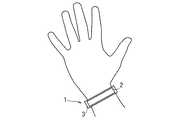
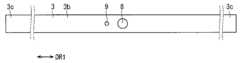
図1は、電子機器1の外観の一例を概略的に示す斜視図である。図2は、電子機器1がユーザに装着されている様子を示す図である。図3及び図4は、それぞれ、電子機器1が装着されていない状態における、当該電子機器1の外観の一例を概略的に示す前面図及び裏面図である。<Appearance of electronic equipment>
FIG. 1 is a perspective view schematically showing an example of the appearance of the
電子機器1は、当該電子機器1を使用するユーザに装着される。図1に示されるように、電子機器1はケース3を備えている。ケース3は、電子機器1の外装の一部を成している。ケース3の材料としては、例えば、ゴムまたは樹脂などの柔軟性を有する材料が採用される。電子機器1は、当該電子機器1の長手方向DR1に沿って、ケース3の裏面3b側に湾曲可能となっている。電子機器1は、ケース3の長手方向DR1における両側の端部3cが互いに接続されることによって環状となる。図2に示されるように、電子機器1は、環状となって、例えばユーザの手首に装着される。図3及び図4に示されるように、電子機器1は、ユーザに装着されていない状態において、細長い板状であって平面視において略長方形を成している。ケース3は、バンド部あるいはベルト部とも呼ばれる。 The
電子機器1では、例えば、ケース3の両側の端部3cのそれぞれに設けられた磁石(図示せず)によって、当該両側の端部3cが互いに接続される。これにより、電子機器1は環状となってユーザに装着される。 In the
なお、ケース3の両側の端部3cの接続方法はこれに限られない。例えば、ケース3の両側の端部3cは、腕時計のベルトのように互いに接続されてもよい。具体的には、ケース3の一方の端部3cに対して貫通孔を設けて、ケース3の他方の端部3cに対して当該貫通孔に係止する留め具を設けてもよい。 In addition, the connection method of the
また、図2の例示では、電子機器1はユーザの手首に装着されているが、ユーザの他の部分に装着されてもよい。例えば、電子機器1は、ユーザの腕あるいは脚などに装着されてもよい。また、電子機器1は、例えばネックレス型の形状であって、ユーザの首に装着されてもよい。後述するように、電子機器1はユーザの生体情報を取得するため、ユーザにおいて、その生体情報を取得するのに適した箇所に装着される。 Moreover, in the illustration of FIG. 2, although the
ケース3の材料として、ゴム又は樹脂などの柔軟性を有する材料を用いることにより、ユーザの手首等にケース3を比較的容易に密着させることができる。これにより、ユーザの生体情報が取得しやすくなる。なお、ケース3の材料は、ゴムまたは樹脂などの柔軟性を有する材料に限らず、ユーザの生体情報が取得可能であれば、アクリル等の比較的硬質な樹脂、金属、またはセラミックなどの材料であってもよい。これらの比較的硬質な材料を用いた場合、電子機器1は、アクセサリーのバングルのような形状または腕時計に用いられる鎖状ベルトのような形状であってもよい。 By using a flexible material such as rubber or resin as the material of the
図1及び図3に示されるように、ケース3の前面3aには、表示部2、操作ボタン4、発光部5及び音出力部6が設けられている。また、図4に示されるように、ケース3の裏面3bには、生体情報取得部8及び近接センサ9が設けられている。 As shown in FIGS. 1 and 3, a
表示部2は、ケース3の前面3aにおける中央部に設けられている。表示部2は、例えば電子ペーパーで構成されている。発光部5は、例えば発光ダイオードを備えており、電子機器1の外部に対して光を出力することが可能である。音出力部6は、スピーカと、当該スピーカが出力する音を電子機器1の外部に取り出すスピーカ穴とを備えている。スピーカ穴は、ケース3の前面3aに設けられている。操作ボタン4は、ユーザによって操作される操作部である。操作ボタン4は、ユーザによって押下される。ケース3の前面3aでは、左側から、操作ボタン4、表示部2、発光部5及び音出力部6が長手方向DR1に沿ってこの順で並んでいる。なお、長手方向DR1におけるこれらの構成要素の順番は、これに限られない。 The
生体情報取得部8は、ケース3の裏面3bの中央部に設けられている。生体情報取得部8はユーザの生体情報を取得することが可能である。生体情報取得部8は、例えば、ユーザの脈拍数を取得することが可能である。近接センサ9は、長手方向DR1において、生体情報取得部8と並んでいる。近接センサ9は、物体の近接を検出することが可能である。なお、近接センサ9および生体情報取得部8の位置は、これに限られず、例えば、長手方向DR1に垂直な方向に沿って並んでいても良い。 The biological
<電子機器の電気的構成>
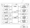
図5は、電子機器1の電気的構成の一例を示すブロック図である。電子機器1には、表示部2、操作ボタン4、発光部5、音出力部6、生体情報取得部8及び近接センサ9以外にも、様々な構成要素が存在する。具体的には、図5に示されるように、電子機器1には、制御部100、無線通信部11、近距離無線通信部12、位置情報取得部13、電池電圧検出部14、計時部16が設けられている。また、電子機器1に電源を供給するために、電子機器1には電池17が接続される。電池17を含めたこれらの構成要素は、ケース3内に収められている。<Electrical configuration of electronic equipment>
FIG. 5 is a block diagram illustrating an example of an electrical configuration of the
制御部100は、一種のコンピュータであって、例えばCPU(Central Processing Unit)101及び記憶部102等を備えている。制御部100は、電子機器1の他の構成要素を制御することによって、電子機器1の動作を統括的に管理することが可能である。 The
記憶部102は、ROM(Read Only Memory)及びRAM(Random Access Memory)等の、CPU101が読み取り可能な非一時的な記録媒体で構成されている。記憶部102には、電子機器1を制御するための、具体的には電子機器1が備える無線通信部11及び表示部2等の各構成要素を制御するための、制御プログラムであるメインプログラム及び複数のアプリケーションプログラム等が記憶されている。制御部100の各種機能は、CPU101が記憶部102内の各種プログラムを実行することによって実現される。 The
なお、記憶部102は、ROM及びRAM以外の、コンピュータが読み取り可能な非一時的な記録媒体を備えていても良い。記憶部102は、例えば、小型のハードディスクドライブ及びSSD(Solid State Drive)等を備えていても良い。また、制御部100の機能の一部または全部は、その機能の実現にソフトウェアが不要なハードウェアによって実現されても構わない。 Note that the
無線通信部11は、アンテナ11aを有している。無線通信部11は、W−CDMA(Wideband Code Division Multiple Access)あるいはLTE(Long Term Evolution)等の無線通信規格に準拠して、アンテナ11aを使用して無線通信を行うことが可能である。無線通信部11は、アンテナ11aでの受信信号に対して増幅処理及びダウンコンバートを行って制御部100に出力することが可能である。制御部100は、入力される受信信号に対して復調処理等を行って、当該受信信号に含まれる情報を取得することが可能である。また無線通信部11は、制御部100で生成された送信信号に対して、アップコンバート及び増幅処理を行って、処理後の送信信号をアンテナ11aから無線送信することが可能である。 The
近距離無線通信部12は、アンテナ12aを有している。近距離無線通信部12は、アンテナ12aを使用して無線通信を行うことが可能である。近距離無線通信部12の通信エリアは、無線通信部11の通信エリアよりも狭くなっている。近距離無線通信部12は、例えば、BLUETOOTH(登録商標)に準拠して通信を行うことが可能である。 The short-range
表示部2は、制御部100に制御されることによって、文字、記号、図形または画像などの各種情報を表示することが可能である。表示部2に表示される情報は、ユーザに視認可能である。 The
操作ボタン4は、ユーザによって押下されると、操作信号を制御部100に出力することが可能である。制御部100は、操作信号が入力されると、所定の処理を実行することが可能である。この所定の処理については後で説明する。 The
発光部5及び音出力部6は制御部100によって制御される。本実施の形態では、発光部5及び音出力部6によって、電子機器1の外部に光及び音を出力することが可能な出力部15が構成されている。 The
生体情報取得部8は、例えば、脈波センサを有している。生体情報取得部8は、脈波センサで検出された脈波に基づいてユーザの脈拍数を計測することが可能である。生体情報取得部8は、計測したユーザの脈拍数を制御部100へと出力することが可能である。脈波センサは、例えば光源と受光素子とを有している。脈波センサでは、光源がユーザの皮膚に向けて光を照射し、受光素子がその反射光を受光する。反射光は血流の変化によって変化するので、生体情報取得部8は当該反射光の変化に基づいて脈拍数を取得することが可能である。生体情報は、例えば、ユーザの健康状態によって変化する情報である。生体情報取得部8が取得する生体情報は、脈拍数に限られない。生体情報取得部8は、体温、血圧あるいは血中酸素濃度などを取得してもよい。また生体情報取得部8は、複数種類の生体情報を取得してもよい。 The biological
位置情報取得部13は、電子機器1の現在位置を取得することが可能である。位置情報取得部13は、例えば、GPS(Global Positioning System)を利用した装置である。位置情報取得部13は、GPS衛星からのGPS信号を受信し、当該GPS信号に基づいて電子機器1の現在位置を示す位置情報を求めることが可能である。位置情報には、例えば、緯度情報と経度情報とが含まれている。 The position
近接センサ9は、例えば赤外線方式の近接センサである。近接センサ9は、当該近接センサ9に対して物体が所定距離以内に近接すると、制御部100に検出信号を出力することが可能である。制御部100は、近接センサ9からの検出信号に基づいて、物体が電子機器1に近接したことを検出することが可能である。上述のように、近接センサ9は、ケース3の裏面3bに設けられていることから、電子機器1は、ユーザの体が当該電子機器1に近接したことを近接センサ9によって検出することができる。 The
電池17は、電子機器1の電源を出力することが可能である。電池17から出力された電源は、電子機器1が備える、制御部100及び無線通信部11などに含まれる各電子部品に対して供給される。電池17は、例えばリチウムイオン二次電池である。電池17は、例えば、電磁誘導などによって非接触充電される。 The
電池電圧検出部14は、電池17の出力電圧(以後、「電池電圧」と呼ぶことがある)を検出して制御部100に通知することが可能である。制御部100は、後述するように、電池電圧検出部14で検出された電池電圧としきい値とを比較し、その比較結果に応じた処理を行うことが可能である。 The battery
計時部16は、現在時刻を計時するとともに現在の日付を計時することが可能である。計時部16は、リアルタイムクロック(RTC)等を備えている。計時部16は、計時した時刻を示す時刻情報と、計時した日付を示す日付情報とを制御部100に出力することが可能である。 The
図6は、制御部100に形成される機能ブロックの一例を示すブロック図である。制御部100は、機能ブロックとして、異常判定部104、装着判定部105、計測部106及び特定部107を備えている。 FIG. 6 is a block diagram illustrating an example of functional blocks formed in the
異常判定部104は、生体情報取得部8が取得したユーザの生体情報に異常があるか否かを判定することが可能である。本実施の形態では、異常判定部104にユーザの脈拍数が入力される。異常判定部104は、例えば、ユーザの脈拍数がゼロになったときに、ユーザの生体情報に異常が発生したと判定する。 The
装着判定部105は、電子機器1がユーザに装着されているか否かを判定することが可能である。近接センサ9が物体の近接を検知すると、装着判定部105は、電子機器1がユーザの手首に装着されていると判定する。 The
特定部107は、ユーザに異常が発生した発生時刻(以後、「異常発生時刻」と呼ぶことがある)を特定することが可能である。具体的には、特定部107は、異常判定部104がユーザの生体情報に異常があると判定したときの時刻を、計時部16が出力する時刻情報に基づいて特定し、特定した時刻を異常発生時刻とする。計測部106は、ユーザに異常が発生してからの経過時間を計測することが可能である。具体的には、特定部107が特定した異常発生時刻からの経過時間を、計時部16が出力する時刻情報に基づいて計測する。 The identifying
<電子機器の動作>
電子機器1は、ユーザの体に装着されて、当該ユーザの生体情報を取得する。異常判定部104がユーザの生体情報に異常があると判定したとき、電子機器1はユーザの異常を周囲に通知する。以下では、電子機器1の動作について詳細に説明する。<Operation of electronic equipment>
The
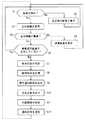
図7は、電子機器1の動作の一例を示すフローチャートである。まずステップS1において、装着判定部105は、近接センサ9の検出信号に基づいて、電子機器1がユーザに装着されているか否かを判定する。ステップS1は所定時間ごとに実行される。 FIG. 7 is a flowchart illustrating an example of the operation of the
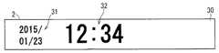
ステップS1において否定的な判定がなされると、ステップS5が実行される。ステップS5において、表示部2は、非装着時画面30を表示する。非装着時画面30は、電子機器1がユーザに装着されていない状態において、表示部2が表示する画面である。図8は、非装着時画面30の一例を概略的に示す図である。図8に示されるように、非装着時画面30は、現在の日付を示す日付情報31及び現在の時刻を示す時刻情報32を含んでいる。これらの情報は計時部16で取得される。 If a negative determination is made in step S1, step S5 is executed. In step S5, the
ステップS5が実行された後に、ステップS1が再度実行される。ステップS1において電子機器1がユーザに装着されていると判定されるまでの間、ステップS1及びステップS5が繰り返し実行される。つまり、表示部2は、ステップS1において電子機器1がユーザに装着されていると判定されるまでの間、非装着時画面30を表示する。 After step S5 is executed, step S1 is executed again. Steps S1 and S5 are repeatedly executed until it is determined in step S1 that the
一方、ステップS1において肯定的な判定がなされると、ステップS2が実行される。ステップS2において、生体情報取得部8は、ユーザの生体情報を取得して当該生体情報を制御部100に出力する。本実施の形態では、生体情報取得部8は、ユーザの脈拍数を取得して、異常判定部104に出力する。 On the other hand, if a positive determination is made in step S1, step S2 is executed. In step S <b> 2, the biological
次に、ステップS3において、異常判定部104は、ユーザの生体情報に異常があるか否かを判定する。異常判定部104は、例えば、ユーザの脈拍数がゼロであるときに、ユーザの生体情報に異常があると判定する。 Next, in step S3, the
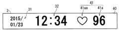
ステップS3において否定的な判定がなされると、ステップS4が実行される。ステップS4において、表示部2は、通常画面40を表示する。通常画面40は、電子機器1がユーザに装着されている状態において、異常判定部104がユーザの生体情報に異常がないと判定しているときに表示される画面である。図9は、通常画面40の一例を概略的に示す図である。図9に示されるように、通常画面40は、非装着時画面30と比較して、ユーザの生体情報を含む情報41をさらに含んでいる。 If a negative determination is made in step S3, step S4 is executed. In step S4, the
情報41は、生体情報取得部8が取得した脈拍数(生体情報)を示す数字41aと、当該数字41aが脈拍数であることを示す図形41aaとを有する。図形41aaは、例えばハート形状である。ユーザは、情報41を見ることによって、自身の生体情報を確認することができる。 The
ステップS4が実行された後に、再度ステップS1が実行される。つまり、電子機器1がユーザに装着されている状態において、ユーザに異常が発生していない間、表示部2は、通常画面40を表示する。 After step S4 is executed, step S1 is executed again. That is, the
一方、ステップS3において肯定的な判定がなされると、後述するステップS6〜S12の一連の処理が実行される。この一連の処理は、ユーザが異常であることを通知するための処理である。 On the other hand, if an affirmative determination is made in step S3, a series of processing in steps S6 to S12 described later is executed. This series of processes is a process for notifying that the user is abnormal.
まずステップS6において、制御部100は表示部2が後述の異常通知画面を表示しているか否かを判定する。ステップS6において肯定的な判定がなされると、ステップS1が実行される。一方、ステップS6において否定的な判定がなされると、ステップS7において、特定部107は、ユーザに異常が発生した発生時刻を特定する。次に、ステップS8において、計測部106は、ユーザに異常が発生してからの経過時間を計測する。 First, in step S6, the
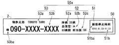
ステップS9において、表示部2は、ユーザの異常を通知する異常通知画面50を表示する。図10は、異常通知画面50の一例を概略的に示す図である。図10に示されるように、異常通知画面50は、異常が発生しているユーザに対する処置に役立つ有用情報50aを含んでいる。これにより、異常通知画面50を見た人は、有用情報50aに基づいて、異常が発生しているユーザに対して適切な処置をすることができる。 In step S9, the
図10の例示では、有用情報50aは、第1情報51、第2情報52及び第3情報53を含んでいる。第1情報51は、ユーザの異常を通知するための異常通知情報である。また、第1情報51は、ユーザに対して処置する人がユーザの異常状態を把握するときに有用な情報でもある。図10の例示では、第1情報51は、ユーザの異常が発生してからの経過時間51aを含む文字列51aaを含む。文字列51aaは、それに含まれる経過時間51aが、どのような経過時間であるかを示している。これにより、ユーザに対して処置する人は、経過時間51aに応じた適切な処置をすることができる。このような処置としては、例えば、経過時間51aに応じたユーザの手当て、あるいは救急車を呼ぶなどがある。 In the example of FIG. 10, the
第2情報52は、救急隊員等の人がユーザの手当てをするときに有用な情報である。図10の例示では、第2情報52は、ユーザの持病名52a、血液型52b及びユーザの主治医に関する主治医情報52cを含んでいる。主治医情報52cは、主治医の名前および主治医が勤務する病院名を含んでいる。このような第2情報52が表示部2に表示されることにより、救急隊員あるいは救急搬送先の医師等は、第2情報に基づいてユーザを手当てするなど、ユーザに対してより適切な処置をすることができる。 The
第3情報53は、ユーザに対して処置する人がユーザの異常を連絡するときに有用な情報である。図10の例示では、第3情報53は、ユーザの名前53a、緊急連絡先53b及び緊急連絡先53bが電話番号であることを示す図形53baを含んでいる。これにより、ユーザに対して処置する人は、ユーザの緊急連絡先53bにユーザが異常であることを連絡するなど、ユーザに対してより適切な処置をすることができる。 The
以上のような第1情報51、第2情報52及び第3情報53は、ユーザに関するユーザ情報であると言える。したがって、異常通知画面50はユーザ情報を含んでいる。一方、非装着時画面30及び通常画面40には、ユーザの生体情報を除くユーザ情報が含まれていない。これにより、電子機器1がユーザに装着されていないときと、ユーザに異常が発生していないときには、生体情報以外のユーザ情報が周囲に漏れることを抑制することができる。 It can be said that the
ステップS10において、出力部15は、光及び音を出力する。具体的には、出力部15が有する、発光部5及び音出力部6が、それぞれ、光及び音を出力する。発光部5は、例えば、あらかじめ登録された所定の発光パターンで発光することによって、ユーザの異常を周囲に通知する。音出力部6は、所定の音を出力することによって、ユーザが異常であることを周囲に通知する。当該所定の音は、音声であってもよいし、音声以外の音であってもよい。なお、ステップS10では、出力部15は光及び音のどちらか一方を出力してもよい。 In step S10, the
ステップS11において、位置情報取得部13は、電子機器1の位置情報を取得する。次にステップS12において、無線通信部11は、ユーザの異常を通知するための通知信号を送信する。通知信号は、例えば、電子メールで送信される。通知信号の送信先のメールアドレスは、ユーザに異常が発生したときに通知する緊急通知先として、有用情報50aなどと共に記憶部102にあらかじめ登録されている。通知信号は、例えば、ステップS11で取得された位置情報を含む。これにより、通知信号を受信した電子装置が、当該通知信号に含まれる位置情報を表示することによって、当該電子装置を使用する緊急通知先の人(ユーザの家族等)は、電子機器1のユーザに異常が発生したことを知るとともに、当該ユーザの位置を特定することができる。なお、通知信号は、ユーザの生体情報を含んでもよい。 In step S <b> 11, the position
ステップS12の後には、再度ステップS1が実行される。電子機器1がユーザに装着されている状態において、ユーザに異常が発生している間、表示部2は、異常通知画面50を表示する。異常通知画面50が表示されている間は、異常通知画面50の経過時間51aは随時更新される。 After step S12, step S1 is executed again. While the
異常判定部104がユーザの生体情報に異常があると判定した後に、ユーザの生体情報が異常でなくなった場合には、つまりステップS3で否定的な判定がされた場合には、表示部2は、ステップS4において、異常通知画面50に代わって通常画面40を表示する。この場合には、無線通信部11は、ユーザが異常でなくなったことを通知する信号を緊急通知先に電子メール等で送信してもよい。 After the
なお、ステップS9と、ステップS10と、ステップS11,S12から成るステップとの実行順序は、入れ替えてもよい。また、ステップS10,S11,S12の少なくとも1つを省略してもよい。 Note that the execution order of Step S9, Step S10, and Steps S11 and S12 may be switched. Further, at least one of steps S10, S11, and S12 may be omitted.
異常通知画面50に含まれる第2情報52及び第3情報53は、例えば、近距離無線通信部12が利用されて、電子機器1に入力されて記憶部102に記憶される。具体的には、近距離無線通信部12と通信可能な、パーソナルコンピュータ等の電子機器に対して第2情報52及び第3情報53が入力される。当該電子機器は、入力された第2情報52及び第3情報53を近距離無線通信部12に送信する。電子機器1では、近距離無線通信部12で受信された第2情報52及び第3情報53は記憶部102に記憶される。 The
第2情報52及び第3情報53の電子機器1への入力方法は他の方法であってもよい。例えば、電子機器1がUSB(Universal Serial Bus)に準拠して外部装置と通信可能であれば、第2情報52及び第3情報53はUSBが使用されて電子機器1に入力されてもよい。 The input method of the
また、電子機器1は、例えば、病院などで販売される。この場合には、第2情報52及び第3情報53は、電子機器1を販売する病院の医師等が、パーソナルコンピュータ等を使用して、電子機器1のユーザについての第2情報52及び第3情報53を当該電子機器1に入力する。第2情報52及び第3情報53は、電子機器1のユーザによって当該電子機器1に入力されてもよい。 The
また、本実施の形態では、電池電圧が電子機器1の電源電圧となっていることから、電池電圧が大きく低下すると、電子機器1はそのほとんどの機能を実行できなくなる。例えば、電池電圧が所定値よりも低くなると、電子機器1は、表示部2を駆動できなくなったり、無線通信部11を使用して他の装置と無線通信できなくなったり、位置情報取得部13を使用して位置情報を取得できなくなる。 Moreover, in this Embodiment, since the battery voltage is the power supply voltage of the
一方、本実施の形態では、表示部2は、電子ペーパーで構成されている。電子ペーパーは、その表示を維持するための電力を必要としない。したがって、電池電圧が所定値よりも低くなり、表示部2が制御部100によって駆動されない場合であっても、言い換えれば、表示部2に十分な電源が供給されない場合であっても、電子ペーパーは、その表示を維持することができる。したがって、表示部2が異常通知画面50等の画面を表示している場合に、電池電圧が所定値よりも低くなり、表示部2が制御部100によって駆動されないときでも、表示部2は、異常通知画面50等の画面を表示し続けることができる。なお、表示部2は、液晶ディプレイまたは有機ELディスプレイなど、電子ペーパー以外で構成されてもよい。 On the other hand, in this Embodiment, the
また、電子機器1がケース3を振動させる振動部を有する場合には、電子機器1は、当該振動部を用いてユーザの異常をユーザ自身に知らせてもよい。例えば制御部100が、通知振動用として登録された振動パターンに基づいて振動部を振動させて、ケース3全体を振動させることによって、ユーザに生体情報の異常を通知してもよい。振動部としては、小型モータあるいは圧電素子などが考えられる。 Moreover, when the
<電池電圧検出部の動作>
本実施の形態では、制御部100は、表示部2に異常通知画面50が表示されているときには、電池電圧検出部14で検出される電池電圧がしきい値よりも小さいか否かを判定する。そして、制御部100は、電池電圧がしきい値よりも小さいと判定したときに、経過時間51aの代わりに発生時刻51bを含む異常通知画面50を表示部2に表示させる。<Operation of battery voltage detector>
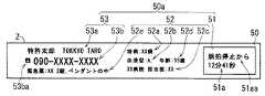
In the present embodiment,
図11は、発生時刻51bを含む異常通知画面50の一例を概略的に示す図である。図11に示されるように、第1情報51は、経過時間51aを含む文字列51aaに代わり、発生時刻51b及び当該発生時刻51bがどのような時刻であるのかを示す文字列51baを含んでいる。 FIG. 11 is a diagram schematically illustrating an example of the
ここで、電池電圧が小さくなると、制御部100は経過時間51aを更新できなくなる。更新されない経過時間51aを含む異常通知画面50が表示されると、周囲に対して正しくない経過時間51aを通知してしまう。本実施の形態では、電池電圧がしきい値よりも小さいときに、経過時間51aの代わりに発生時刻51bを含む異常通知画面50が表示されることから、ユーザの異常状態を把握するときに有用な情報を通知しつつ、正しくない経過時間51aを通知することを抑制することができる。なお、電池電圧の値にかかわらず、図11に示されるような、発生時刻51bを含む異常通知画面50が表示部2に表示されてもよい。 Here, when the battery voltage decreases, the
<操作ボタンによる異常通知>
上記のように、電子機器1は、異常判定部104がユーザの生体情報に異常があると判定したときに、ユーザが異常であることを通知する。本実施の形態では、これに加えて、操作ボタン4が操作されたときに、電子機器1がユーザの異常を通知する。以降、ユーザの異常を通知するための操作ボタン4に対する操作を、異常通知操作とも呼ぶことがある。<Notification of abnormalities with operation buttons>
As described above, when the
制御部100は、操作ボタン4が押下されると、図12に示される異常通知画面50を表示部2に表示させる。図12に示される異常通知画面50では、第1情報51は、異常通知操作からの経過時間51cを含む文字列51caを含む。文字列51caは、それに含まれる経過時間51cが、どのような経過時間であるかを示している。また、制御部100は、異常通知画面50を表示するとともに、ステップS10と同様に、出力部15から光及び音を出力させる。 When the
このように、操作ボタン4が操作されたときに、電子機器1が、表示部2及び出力部15を使用して、ユーザの異常を通知することによって、ユーザは、自身に異常が発生したときに自分の意志で電子機器1に異常を通知させることができる。 As described above, when the
なお、図12に示される異常通知画面50が表示されている状態において、操作ボタン4が押下されたときには、電子機器1は、ユーザの異常を通知することを停止してもよい。このとき、表示部2は、異常通知画面50に代わり通常画面40を表示してもよい。 Note that when the
<変形例>
図10の例示では、第2情報52は、ユーザの持病名52a、血液型52b及び主治医情報52cを含んでいるが、第2情報52は、これらの少なくとも一つを含んでいてもよい。また、第2情報52は、ユーザの持病名52a、血液型52b及び主治医情報52c以外の情報を含んでいてもよい。図13は、異常通知画面50の一例を概略的に示す図である。図13に示される異常通知画面50では、第2情報52がユーザの年齢52d及びユーザの薬情報52eをさらに含んでいる。薬情報52eは、例えば、ユーザの持病に対する薬に関する情報であって、薬の名称及び所持している場所などの情報を含んでいる。これにより、ユーザに対して処置する人は、薬情報52eに基づいてユーザに薬を飲ませてあげるなど、ユーザに対してより適切な処置が可能になる。<Modification>
In the illustration of FIG. 10, the
上記の例では、異常判定部104は、ユーザの生体情報の値がゼロになったときに、ユーザの生体情報に異常があると判定しているが、その他の方法でユーザの生体情報に異常があるか否かを判定してもよい。例えば、異常判定部104は、生体情報取得部8から入力される生体情報の値が所定範囲外になったときに、当該生体情報が異常であると判定してもよい。言い換えれば、異常判定部104は、ユーザの生体情報の値が、下限値よりも小さくなったときと、上限値よりも大きくなったときに、当該生体情報が異常であると判定してもよい。 In the above example, the
図14は、ユーザの生体情報の値が所定範囲外になったときに表示される、異常通知画面50の一例を概略的に示す図である。図14に示されるように、第1情報51は、脈拍数を示す数字41aと、当該数字41aが異常であることを示す文字列41abとを含んでいる。 FIG. 14 is a diagram schematically illustrating an example of the
異常判定部104がユーザの生体情報に異常があるか否かを判定するための所定範囲は、例えばユーザの健康状態などによって設定され、記憶部102に記憶されている。 The predetermined range for the
また、上記の例では、電子機器1は一種類の生体情報を取得していたが、電子機器1は、複数種類の生体情報を取得してもよい。例えば、生体情報取得部8は、脈拍数に加えてユーザの体温を取得してもよい。この場合には、生体情報取得部8は、ユーザの体温を検出する温度センサを備える。 In the above example, the
図15は、ユーザの脈拍数及び体温を含む通常画面40の一例を概略的に示す図である。図15に示されるように、ユーザの生体情報を含む情報41は、生体情報取得部8で取得される脈拍数を示す数字41aと、体温を示す数字41bとを含んでいる。 FIG. 15 is a diagram schematically illustrating an example of a
生体情報取得部8が体温を取得する場合には、異常判定部104は、生体情報取得部8で取得される体温が所定範囲外になったときに、当該体温に異常があると判定してもよい。図16は、体温に異常があることを通知する異常通知画面50の一例を概略的に示す図である。図16に示されるように、第1情報51は、体温を示す数字41bと、当該数字41bが異常であることを示す文字列41baとを含んでいる。 When the biological
なお、図8の非装着時画面30および図9の通常画面40はいずれも何らかの情報を含んでいるが、情報を含まない、すなわち、非装着時および通常時(装着時かつユーザに異常がない時)に表示部2に何も情報が表示されなくてもよい。この場合、ユーザの生体情報に異常があると判定された場合にのみ、表示部2に情報が表示されることから、例えば、非装着時および通常時に時刻情報32等の情報を表示する必要がないため、電子機器1の消費電力を低減することができる。また、非装着時画面30および通常画面40のいずれか一方は情報を含まない、とすることもできる。 Note that the
また、表示部2に何も情報が表示されていない場合、例えば、操作ボタン4が一回押下されると、表示部2に時刻情報32や生体情報を含む情報41などの情報を表示させ、2回押下されると、表示部2に異常通知画面50を表示させてもよい。この場合、操作ボタン4が1回押下されることにより表示部2に表示された情報は、所定期間(例えば、数時間)が経過すると、その情報を非表示にしてもよい。なお、操作ボタン4の操作は、上述したものに限られず、例えば、操作ボタン4が押下される時間が所定時間未満(短押し)であれば、表示部2に時刻情報32や生体情報を含む情報41などの情報を表示させ、操作ボタン4が押下される時間が所定時間以上(長押し)であれば、表示部2に異常通知画面50を表示させてもよい。 In addition, when no information is displayed on the
以上のように、電子機器1は詳細に説明されたが、上記した説明は、全ての局面において例示であって、この開示がそれに限定されるものではない。また、上述した各種変形例は、相互に矛盾しない限り組み合わせて適用可能である。そして、例示されていない無数の変形例が、この開示の範囲から外れることなく想定され得るものと解される。 As mentioned above, although the
1 電子機器
2 表示部
8 生体情報取得部
50 異常通知画面
50a 有用情報
51 第1情報
51a 経過時間
51aa 文字列
52 第2情報
52a 持病名
52b 血液型
52c 主治医情報
53 第3情報
53a 名前
53b 緊急連絡先
53ba 図形
104 異常判定部DESCRIPTION OF
Claims (13)
Translated fromJapanese前記ユーザの生体情報を取得する生体情報取得部と、
前記生体情報に異常があるか否かを判定する異常判定部と、
前記異常判定部が前記生体情報に異常があると判定したとき、前記ユーザの異常を通知する異常通知画面を表示する表示部と
を備える、電子機器。An electronic device worn on the user's body,
A biometric information acquisition unit for acquiring biometric information of the user;
An abnormality determination unit for determining whether or not there is an abnormality in the biological information;
An electronic device comprising: a display unit that displays an abnormality notification screen for notifying the abnormality of the user when the abnormality determination unit determines that the biological information is abnormal.
前記異常通知画面は、前記ユーザに対する処置に役立つ有用情報を含む、電子機器。The electronic device according to claim 1,
The abnormality notification screen is an electronic device including useful information useful for treatment for the user.
前記ユーザに異常が発生してからの経過時間を計測する計測部をさらに備え、
前記有用情報は、前記経過時間を含む、電子機器。The electronic device according to any one of claims 1 and 2,
A measuring unit that measures an elapsed time since the occurrence of an abnormality in the user;
The useful information includes the elapsed time.
前記ユーザに異常が発生した発生時刻を特定する特定部をさらに備え、
前記有用情報は、前記発生時刻を含む、電子機器。An electronic device according to any one of claims 1 to 3,
Further comprising a specifying unit for specifying an occurrence time when an abnormality has occurred in the user;
The useful information includes the electronic device including the generation time.
前記有用情報は、前記ユーザの持病名、前記ユーザの血液型及び前記ユーザの主治医に関する主治医情報の少なくとも一つを含む、電子機器。An electronic device according to any one of claims 1 to 4,
The said useful information is an electronic device containing at least one of the said doctor's disease name, the said user's blood type, and the attending physician information regarding the said attending physician.
前記有用情報は、前記ユーザの名前及び連絡先を含む、電子機器。An electronic device according to any one of claims 1 to 5,
The useful information includes an electronic device including a name and contact information of the user.
前記異常判定部が前記生体情報に異常があると判定したとき、前記ユーザの異常を通知する通知信号を無線送信する送信部をさらに備える、電子機器。An electronic device according to any one of claims 1 to 6,
An electronic apparatus, further comprising: a transmission unit that wirelessly transmits a notification signal for notifying the abnormality of the user when the abnormality determination unit determines that the biological information is abnormal.
前記電子機器の位置を示す位置情報を取得する位置情報取得部をさらに備え、
前記通知信号は、前記位置情報を含む、電子機器。The electronic device according to claim 7,
A position information acquisition unit that acquires position information indicating the position of the electronic device;
The notification signal is an electronic device including the position information.
前記表示部は電子ペーパーである、電子機器。An electronic device according to any one of claims 1 to 8,
The display device is an electronic device, which is electronic paper.
前記ユーザに異常が発生してからの経過時間を計測する計測部と、
前記ユーザに異常が発生した発生時刻を特定する特定部と
をさらに備え、
前記電子機器は電池で駆動し、
前記表示部は電子ペーパーであり、
前記表示部が前記経過時間を含む前記異常通知画面を表示している状態において、前記電池の電圧がしきい値よりも小さくなったとき、前記表示部は、前記経過時間の代わりに前記発生時刻を含む前記異常通知画面を表示する、電子機器。The electronic device according to any one of claims 1 and 2,
A measuring unit for measuring an elapsed time after the occurrence of an abnormality in the user;
A specifying unit that specifies an occurrence time when an abnormality has occurred in the user;
The electronic device is driven by a battery,
The display unit is electronic paper,
In the state where the display unit displays the abnormality notification screen including the elapsed time, when the voltage of the battery becomes lower than a threshold value, the display unit displays the occurrence time instead of the elapsed time. An electronic device that displays the abnormality notification screen including:
ユーザが操作する操作部をさらに備え、
前記表示部は、前記異常判定部での判定結果にかかわらず、前記操作部が操作されたとき前記異常通知画面を表示する、電子機器。The electronic device according to any one of claims 1 to 10,
It further includes an operation unit operated by the user,
The display device is an electronic device that displays the abnormality notification screen when the operation unit is operated regardless of a determination result in the abnormality determination unit.
前記異常判定部が前記生体情報に異常があると判定したときに光及び音の少なくとも一方を出力する出力部をさらに備える、電子機器。An electronic device according to any one of claims 1 to 11,
An electronic device further comprising an output unit that outputs at least one of light and sound when the abnormality determination unit determines that the biological information is abnormal.
前記異常判定部が前記生体情報に異常が無いと判定したときに前記表示部が表示する通常画面は、前記生体情報を除く、前記ユーザに関するユーザ情報を含まない、電子機器。An electronic device according to any one of claims 1 to 12,
The normal screen displayed by the display unit when the abnormality determination unit determines that the biological information is normal, the electronic device excludes the biological information and does not include user information regarding the user.
Priority Applications (3)
| Application Number | Priority Date | Filing Date | Title |
|---|---|---|---|
| JP2015032562AJP6422794B2 (en) | 2015-02-23 | 2015-02-23 | Electronics |
| US15/552,792US10424181B2 (en) | 2015-02-23 | 2016-02-23 | Electronic apparatus |
| PCT/JP2016/055129WO2016136687A1 (en) | 2015-02-23 | 2016-02-23 | Electronic device |
Applications Claiming Priority (1)
| Application Number | Priority Date | Filing Date | Title |
|---|---|---|---|
| JP2015032562AJP6422794B2 (en) | 2015-02-23 | 2015-02-23 | Electronics |
Publications (2)
| Publication Number | Publication Date |
|---|---|
| JP2016154578Atrue JP2016154578A (en) | 2016-09-01 |
| JP6422794B2 JP6422794B2 (en) | 2018-11-14 |
Family
ID=56789049
Family Applications (1)
| Application Number | Title | Priority Date | Filing Date |
|---|---|---|---|
| JP2015032562AActiveJP6422794B2 (en) | 2015-02-23 | 2015-02-23 | Electronics |
Country Status (3)
| Country | Link |
|---|---|
| US (1) | US10424181B2 (en) |
| JP (1) | JP6422794B2 (en) |
| WO (1) | WO2016136687A1 (en) |
Cited By (3)
| Publication number | Priority date | Publication date | Assignee | Title |
|---|---|---|---|---|
| DE112018005889T5 (en) | 2017-12-27 | 2020-07-30 | Omron Healthcare Co., Ltd. | CAUTION WARNING SYSTEM, INFORMATION PROCESSING DEVICE, INFORMATION PROCESSING PROCEDURE AND PROGRAM |
| JP2021129998A (en)* | 2018-02-01 | 2021-09-09 | アルプスアルパイン株式会社 | Biological monitoring system, information processing device, information processing method and program |
| JP2022072625A (en)* | 2020-10-30 | 2022-05-17 | 株式会社トーカイ | Monitoring system, monitored person terminal, and monitoring method |
Families Citing this family (3)
| Publication number | Priority date | Publication date | Assignee | Title |
|---|---|---|---|---|
| WO2018051975A1 (en)* | 2016-09-14 | 2018-03-22 | Dynamic Brain Lab合同会社 | Biological information measurement device |
| JP7125866B2 (en)* | 2018-06-18 | 2022-08-25 | 富士通コンポーネント株式会社 | Cassette and system |
| WO2022044201A1 (en)* | 2020-08-27 | 2022-03-03 | 株式会社ユタカ電子製作所 | Monitoring assistance system and monitoring assistance method |
Citations (3)
| Publication number | Priority date | Publication date | Assignee | Title |
|---|---|---|---|---|
| JPH05161610A (en)* | 1991-12-13 | 1993-06-29 | Nippon Colleen Kk | Emergency alarm |
| JP2006239084A (en)* | 2005-03-02 | 2006-09-14 | Takahashi Kogei Kenkyusho:Kk | Monitoring method of condition measuring device by portable terminal |
| JP2013169438A (en)* | 2012-02-23 | 2013-09-02 | Nippon Koden Corp | Monitor device |
Family Cites Families (42)
| Publication number | Priority date | Publication date | Assignee | Title |
|---|---|---|---|---|
| DE69401488T2 (en)* | 1993-06-23 | 1997-07-24 | Presmatec Sa | PERSONAL OBJECT WITH MEDICAL INFORMATION |
| US6177873B1 (en)* | 1999-02-08 | 2001-01-23 | International Business Machines Corporation | Weather warning apparatus and method |
| US20060229520A1 (en)* | 2005-04-08 | 2006-10-12 | Shunzo Yamashita | Controller for sensor node, measurement method for biometric information and its software |
| US20060267760A1 (en)* | 2005-05-20 | 2006-11-30 | Gard Dog, Llc | Child safety alarm |
| US7602303B2 (en)* | 2006-06-28 | 2009-10-13 | Randy Douglas | Personal crime prevention bracelet |
| US20080068932A1 (en)* | 2006-09-14 | 2008-03-20 | Bennie Mosley | Wrist watch for monitoring diabetes |
| US20080266118A1 (en)* | 2007-03-09 | 2008-10-30 | Pierson Nicholas J | Personal emergency condition detection and safety systems and methods |
| US20090322513A1 (en)* | 2008-06-27 | 2009-12-31 | Franklin Dun-Jen Hwang | Medical emergency alert system and method |
| US8521122B2 (en)* | 2009-01-28 | 2013-08-27 | Blackberry Limited | Mobile device user interface for displaying emergency information |
| JP5395484B2 (en) | 2009-03-25 | 2014-01-22 | シチズンホールディングス株式会社 | Mounting device |
| US20110205851A1 (en)* | 2010-02-23 | 2011-08-25 | Jared Harris | E-Watch |
| US20130143519A1 (en)* | 2010-07-29 | 2013-06-06 | J&M I.P. Holding Company, Llc | Fall-Responsive Emergency Device, System, and Method |
| JP2013533565A (en)* | 2010-07-29 | 2013-08-22 | ジェイ アンド エム アイ.ピー.ホールディング カンパニー,エルエルシー | Emergency device, system and method for falling |
| US20130135097A1 (en)* | 2010-07-29 | 2013-05-30 | J&M I.P. Holding Company, Llc | Fall-Responsive Emergency Device |
| US20120052802A1 (en)* | 2010-08-24 | 2012-03-01 | Nokia Corporation | Advertisement of an existing wireless connection |
| WO2012174420A2 (en)* | 2011-06-17 | 2012-12-20 | The Research Foundation Of The State Of New York | Detecting and responding to sentinel events |
| US8832233B1 (en)* | 2011-07-20 | 2014-09-09 | Google Inc. | Experience sharing for conveying communication status |
| US20130109997A1 (en)* | 2011-11-02 | 2013-05-02 | Peter Linke | System for monitoring biological data |
| US9069333B1 (en)* | 2012-08-14 | 2015-06-30 | Natascha Romans | Personal alarm watch |
| US20150035672A1 (en)* | 2012-12-07 | 2015-02-05 | Shannon Housley | Proximity tracking system |
| JP6030464B2 (en)* | 2013-02-04 | 2016-11-24 | 日本光電工業株式会社 | Biological information monitor |
| US8981925B2 (en)* | 2013-03-11 | 2015-03-17 | 3M Innovative Properties Company | System, method, and apparatus for detecting wireless devices |
| US9835496B2 (en)* | 2013-04-08 | 2017-12-05 | Ann Balboni | Fever alert system |
| US9569625B2 (en)* | 2013-06-11 | 2017-02-14 | Google Inc. | Wearable device multi-mode system |
| US9606721B2 (en)* | 2013-07-22 | 2017-03-28 | Lg Electronics Inc. | Mobile terminal and control method thereof |
| US8976965B2 (en)* | 2013-07-30 | 2015-03-10 | Google Inc. | Mobile computing device and wearable computing device having automatic access mode control |
| US10198726B2 (en)* | 2013-08-08 | 2019-02-05 | Apple Inc. | Low power mode for payment transactions |
| US9508241B2 (en)* | 2013-09-11 | 2016-11-29 | Christopher DePascale | Wearable personal locator device with removal indicator |
| US20150102208A1 (en)* | 2013-10-02 | 2015-04-16 | The Joan & Irwin Jacobs Technion-Cornell Innovation Institute (Jacobs Institute) | Wearable system and method to measure and monitor ultraviolet, visible light, and infrared radiations in order to provide personalized medical recommendations, prevent diseases, and improve disease management |
| GB2520025B (en)* | 2013-11-06 | 2021-04-14 | Arm Ip Ltd | Calibrating proximity detection for a wearable processing device |
| US20150227245A1 (en)* | 2014-02-10 | 2015-08-13 | Polyera Corporation | Attachable Device with Flexible Electronic Display Orientation Detection |
| US9715363B2 (en)* | 2014-03-27 | 2017-07-25 | Lenovo (Singapore) Pte. Ltd. | Wearable device with public display and private display areas |
| US9360364B2 (en)* | 2014-05-30 | 2016-06-07 | Microsoft Technology Licensing, Llc | Sensory-and-logic system and method having ultraviolet light estimation from visible light |
| KR102190062B1 (en)* | 2014-06-02 | 2020-12-11 | 엘지전자 주식회사 | Wearable device and method for controlling the same |
| CN105182726B (en)* | 2014-06-17 | 2019-03-22 | 中兴通讯股份有限公司 | A kind of automatic usual method of smartwatch and the smartwatch |
| US9747433B2 (en)* | 2014-06-24 | 2017-08-29 | Google Technology Holdings, LLC | Wearable electronic device and method for securing same |
| US10121335B2 (en)* | 2014-07-18 | 2018-11-06 | Google Technology Holdings LLC | Wearable haptic device for the visually impaired |
| US9632532B2 (en)* | 2014-07-23 | 2017-04-25 | Lenovo (Singapore) Pte. Ltd. | Configuring wearable devices |
| US9770185B2 (en)* | 2014-08-06 | 2017-09-26 | Verily Life Sciences Llc | Sharing a single electrode between skin resistance and capacitance measurements |
| US20160065655A1 (en)* | 2014-08-29 | 2016-03-03 | Microsoft Technology Licensing, Llc | Active and passive chained subscriptions |
| US9901301B2 (en)* | 2014-12-12 | 2018-02-27 | Ebay Inc. | Coordinating relationship wearables |
| US9547971B2 (en)* | 2014-12-27 | 2017-01-17 | Intel Corporation | Technologies for determining a threat assessment based on fear responses |
- 2015
- 2015-02-23JPJP2015032562Apatent/JP6422794B2/enactiveActive
- 2016
- 2016-02-23USUS15/552,792patent/US10424181B2/enactiveActive
- 2016-02-23WOPCT/JP2016/055129patent/WO2016136687A1/ennot_activeCeased
Patent Citations (3)
| Publication number | Priority date | Publication date | Assignee | Title |
|---|---|---|---|---|
| JPH05161610A (en)* | 1991-12-13 | 1993-06-29 | Nippon Colleen Kk | Emergency alarm |
| JP2006239084A (en)* | 2005-03-02 | 2006-09-14 | Takahashi Kogei Kenkyusho:Kk | Monitoring method of condition measuring device by portable terminal |
| JP2013169438A (en)* | 2012-02-23 | 2013-09-02 | Nippon Koden Corp | Monitor device |
Cited By (4)
| Publication number | Priority date | Publication date | Assignee | Title |
|---|---|---|---|---|
| DE112018005889T5 (en) | 2017-12-27 | 2020-07-30 | Omron Healthcare Co., Ltd. | CAUTION WARNING SYSTEM, INFORMATION PROCESSING DEVICE, INFORMATION PROCESSING PROCEDURE AND PROGRAM |
| JP2021129998A (en)* | 2018-02-01 | 2021-09-09 | アルプスアルパイン株式会社 | Biological monitoring system, information processing device, information processing method and program |
| JP2022072625A (en)* | 2020-10-30 | 2022-05-17 | 株式会社トーカイ | Monitoring system, monitored person terminal, and monitoring method |
| JP7355721B2 (en) | 2020-10-30 | 2023-10-03 | 株式会社トーカイ | Monitoring system, monitored person terminal, and monitoring method |
Also Published As
| Publication number | Publication date |
|---|---|
| US10424181B2 (en) | 2019-09-24 |
| WO2016136687A1 (en) | 2016-09-01 |
| JP6422794B2 (en) | 2018-11-14 |
| US20190035247A1 (en) | 2019-01-31 |
Similar Documents
| Publication | Publication Date | Title |
|---|---|---|
| JP6422794B2 (en) | Electronics | |
| US12064207B2 (en) | Patient monitoring device with remote alert | |
| US10157528B2 (en) | Geolocation bracelet, system, and methods | |
| US20180116607A1 (en) | Wearable monitoring device | |
| US9311789B1 (en) | Systems and methods for sensorimotor rehabilitation | |
| US20180132768A1 (en) | Living body monitoring system, portable electronic apparatus, living body monitoring program, computer readable recording medium, living body monitoring method, display device and display method | |
| US9215577B2 (en) | Wearable healthcare device | |
| US10413218B2 (en) | Wristband-type arm movement determination device and wristband-type activity tracker | |
| US20150130613A1 (en) | Selectively available information storage and communications system | |
| US10874313B2 (en) | Heartrate tracking techniques | |
| JP2018068478A (en) | Biological monitoring system, portable electronic apparatus, biological monitoring program, computer-readable recording medium, and biological monitoring method | |
| JP2014054479A (en) | Biological information notification apparatus, biological information notification method, and biological information notification program | |
| KR101821858B1 (en) | A mehthod of measuring a resting heart rate | |
| CN110139600B (en) | User terminal device | |
| JP2023544496A (en) | wearable tag | |
| EP3189778A1 (en) | Physiological status monitoring device | |
| US11495351B2 (en) | Health monitoring system and method thereof | |
| US11172861B2 (en) | Detection devices and monitoring systems including detection devices | |
| US10327696B2 (en) | Action notification system, exercise information measurement apparatus, electronic device, action notification method, and action notification program | |
| CN111511273B (en) | Information processing apparatus, information processing method, and storage medium | |
| CN115381414A (en) | Detection device, detection system and detection method | |
| JP6790456B2 (en) | Biometric device and biometric method | |
| US12013669B1 (en) | System for a proximity sensing wristwatch device | |
| Amor et al. | Unobtrusive wearable technology for health monitoring |
Legal Events
| Date | Code | Title | Description |
|---|---|---|---|
| A621 | Written request for application examination | Free format text:JAPANESE INTERMEDIATE CODE: A621 Effective date:20180112 | |
| A131 | Notification of reasons for refusal | Free format text:JAPANESE INTERMEDIATE CODE: A131 Effective date:20180130 | |
| A521 | Request for written amendment filed | Free format text:JAPANESE INTERMEDIATE CODE: A523 Effective date:20180328 | |
| A131 | Notification of reasons for refusal | Free format text:JAPANESE INTERMEDIATE CODE: A131 Effective date:20180703 | |
| A521 | Request for written amendment filed | Free format text:JAPANESE INTERMEDIATE CODE: A523 Effective date:20180829 | |
| TRDD | Decision of grant or rejection written | ||
| A01 | Written decision to grant a patent or to grant a registration (utility model) | Free format text:JAPANESE INTERMEDIATE CODE: A01 Effective date:20181002 | |
| A61 | First payment of annual fees (during grant procedure) | Free format text:JAPANESE INTERMEDIATE CODE: A61 Effective date:20181017 | |
| R150 | Certificate of patent or registration of utility model | Ref document number:6422794 Country of ref document:JP Free format text:JAPANESE INTERMEDIATE CODE: R150 |