JP2016151461A - Weighting device - Google Patents
Weighting deviceDownload PDFInfo
- Publication number
- JP2016151461A JP2016151461AJP2015028561AJP2015028561AJP2016151461AJP 2016151461 AJP2016151461 AJP 2016151461AJP 2015028561 AJP2015028561 AJP 2015028561AJP 2015028561 AJP2015028561 AJP 2015028561AJP 2016151461 AJP2016151461 AJP 2016151461A
- Authority
- JP
- Japan
- Prior art keywords
- load
- signal
- circuit
- strain
- input
- Prior art date
- Legal status (The legal status is an assumption and is not a legal conclusion. Google has not performed a legal analysis and makes no representation as to the accuracy of the status listed.)
- Pending
Links
- 230000003321amplificationEffects0.000claimsabstractdescription35
- 238000003199nucleic acid amplification methodMethods0.000claimsabstractdescription35
- 238000005303weighingMethods0.000claimsdescription178
- 230000004044responseEffects0.000claimsdescription19
- 230000001052transient effectEffects0.000claimsdescription14
- 230000003068static effectEffects0.000abstractdescription59
- 238000006243chemical reactionMethods0.000abstractdescription45
- 230000005856abnormalityEffects0.000description58
- 238000012545processingMethods0.000description46
- 238000005259measurementMethods0.000description39
- 230000008859changeEffects0.000description31
- 238000001514detection methodMethods0.000description29
- 230000014509gene expressionEffects0.000description22
- 238000000034methodMethods0.000description17
- 230000008569processEffects0.000description17
- 238000001914filtrationMethods0.000description13
- 230000006870functionEffects0.000description12
- 230000007423decreaseEffects0.000description8
- 230000005540biological transmissionEffects0.000description7
- 230000002238attenuated effectEffects0.000description6
- 230000006872improvementEffects0.000description4
- 230000002159abnormal effectEffects0.000description3
- 230000006835compressionEffects0.000description3
- 238000007906compressionMethods0.000description3
- 238000003379elimination reactionMethods0.000description3
- 230000005284excitationEffects0.000description3
- 230000002542deteriorative effectEffects0.000description2
- 230000000694effectsEffects0.000description2
- 238000012805post-processingMethods0.000description2
- 230000009286beneficial effectEffects0.000description1
- 230000007797corrosionEffects0.000description1
- 238000005260corrosionMethods0.000description1
- 230000008030eliminationEffects0.000description1
- 238000011156evaluationMethods0.000description1
- 230000007717exclusionEffects0.000description1
- 238000009434installationMethods0.000description1
- 230000003287optical effectEffects0.000description1
- 230000004043responsivenessEffects0.000description1
Images


Landscapes
- Measurement Of Force In General (AREA)
Abstract
Description
Translated fromJapanese本発明は、計量装置に関し、特に、計量精度の向上を図る計量装置に関する。 The present invention relates to a weighing device, and more particularly, to a weighing device that improves weighing accuracy.
計量精度の向上を図ろうとする計量装置として、従来、例えば特許文献1に開示された重量選別機がある。この従来技術によれば、計量台上を被計量物が滑走されながら、当該被計量物の重量が測定される。従って例えば、ベルトコンベヤやチェーンコンベヤ等の被計量物を強制的に搬送するための強制搬送手段を備える言わば一般的な重量選別機とは異なり、当該強制搬送手段が不要であり、その分、計量台を含む計量部の軽量化が図られる。この結果、計量部の固有振動数が大きくなり、これに伴い、計量部から出力される荷重信号の過渡応答が早くなり、高速計量に適したものとなる。即ち、重量選別機という短い時間内に被計量物の重量を測定しなければならない、いわゆる動的秤にとって、高い計量精度が得られ、つまり高い動的計量精度が得られる。また、強制搬送手段を構成するモータやプーリ等の回転体も存在しないので、これらの偏心荷重に起因する振動ノイズも発生しない。この振動ノイズは、計量部の固有振動数よりも小さい周波数のノイズであるので、これを例えばフィルタ回路によって減衰させようとすると、荷重信号にさらなる遅れが生じる。従来技術によれば、このようなフィルタ回路が不要であるので、荷重信号にさらなる遅れが生じることはない。このこともまた、高速計量に好都合であり、つまり動的計量精度の向上に大きく貢献する。加えて、従来技術によれば、計量台上と被計量物との間の摩擦係数が変化することによって、当該計量台上での被計量物の滞在時間が変化したとしても、この滞在時間に応じて重量測定値が補正されるので、計量精度(動的計量精度)をより高めることが可能である、とされている。 Conventionally, there is a weight sorter disclosed in, for example,
ところで、上述の従来技術では、例えばその図1および図2に示されるように、計量部を構成する計量台は、荷重センサとしての歪みゲージ式ロードセルまたはフォースバランス(電磁力平衡)式ロードセルを備えている。この荷重センサは、自身に印加された荷重の大きさに応じた態様の、例えば電圧の、荷重信号を出力し、厳密には当該荷重の大きさの変化量に応じた電圧変化量を示す荷重信号を出力する。そして、この荷重センサから出力された荷重信号は、従来技術の図4に示されるように、演算増幅器によって、厳密には演算増幅器を用いた増幅回路によって、増幅された後、A/D変換器によってアナログ信号からデジタル信号に変換される。さらに、このA/D変換器による変換後のデジタル荷重信号は、入出力回路を介して中央演算処理回路(CPU:Central Processing Unit)に入力される。中央演算処理回路は、このデジタル荷重信号に基づいて、被計量物の重量測定値を求める。 By the way, in the above-mentioned prior art, for example, as shown in FIGS. 1 and 2, the weighing table constituting the weighing unit includes a strain gauge type load cell or a force balance (electromagnetic force balance) type load cell as a load sensor. ing. This load sensor outputs a load signal of, for example, a voltage in a mode corresponding to the magnitude of the load applied to itself, strictly, a load indicating a voltage change amount corresponding to the change amount of the load size. Output a signal. Then, as shown in FIG. 4 of the prior art, the load signal output from the load sensor is amplified by an operational amplifier, strictly by an amplifier circuit using the operational amplifier, and then the A / D converter. Is converted from an analog signal to a digital signal. Further, the digital load signal after conversion by the A / D converter is input to a central processing unit (CPU) via an input / output circuit. The central processing circuit obtains a weight measurement value of the object to be weighed based on the digital load signal.
ここで、演算増幅器は、その内部で雑音を発生することが、知られている。この内部雑音は、入力換算雑音と呼ばれており、荷重信号にとっては当然に不必要な存在である。例えば、荷重センサに或る大きさの荷重が印加されたときの無負荷時からの荷重信号の電圧変化量がEであり、演算増幅器の入力換算雑音の特に電圧成分がenである、とすると、当該演算増幅器を含む増幅回路の入力側(増幅前)における入力換算雑音電圧enに対する荷重信号の電圧変化量Eの比率、いわゆるSN比(S/N_in)は、次の式1のように表される。 Here, it is known that the operational amplifier generates noise therein. This internal noise is called input conversion noise and is naturally unnecessary for the weight signal. For example, suppose that the voltage change amount of the load signal from no load when a load of a certain magnitude is applied to the load sensor is E, and especially the voltage component of the input conversion noise of the operational amplifier is en. The ratio of the voltage change amount E of the load signal to the input converted noise voltage en on the input side (before amplification) of the amplifier circuit including the operational amplifier, that is, the so-called SN ratio (S / N_in) is expressed by the following
《式1》
S/N_in=E/en<<
S / N_in = E / en
そして、増幅回路の利得がGである、とすると、当該増幅回路の出力側(増幅後)のSN比(S/N_out)は、次の式2のように表される。 Then, assuming that the gain of the amplifier circuit is G, the SN ratio (S / N_out) on the output side (after amplification) of the amplifier circuit is expressed as the following
《式2》
S/N_out=(G・E)/(G・en)=E/en<<
S / N_out = (GE) / (G.en) = E / en
この式2と上述の式1とから分かるように、増幅回路の出力側のSN比は、当該増幅回路の入力側のSN比と等価(S/N_in=S/N_out)である。このSN比が低いと、重量表示値が不安定となる(言わばふらつく)。このSN比を向上させるには、(入力換算雑音電圧enが不変であるので)荷重信号の電圧変化量Eを大きくする必要があり、そのために例えば、定格容量(バネ定数)の小さい荷重センサを採用することが、考えられる。しかし、定格容量の小さい荷重センサほど、その固有振動数が小さく、従ってその分、荷重信号に含まれる過渡応答振動の周波数が小さくなり、とりわけ、荷重センサに荷重が印加された直後に現れる振幅の大きなオーバシュート状の当該過渡応答振動が収束するのに長い時間が掛かり、ひいては動的計量精度が低下する、という問題がある。 As can be seen from
また、これとは別に例えば、荷重センサが歪みゲージ式ロードセルである場合には、この歪みゲージによって形成されたブリッジ回路に供給される電源電圧(励磁電圧)を上げることで、荷重信号の電圧変化量Eを大きくし、ひいてはSN比を向上させる、という方策も考えられる。しかし、この場合は、歪みゲージを含むブリッジ回路の消費電力が増大して、当該ブリッジ回路が発熱し、これにより、荷重信号に大きな温度ドリフトが生じて、これを補償するのが却って難しい、という問題がある。このことは特に、計量装置の稼働運転開始直後のウォーミングアップ中に顕著になる。 In addition, for example, when the load sensor is a strain gauge type load cell, the voltage change of the load signal is increased by increasing the power supply voltage (excitation voltage) supplied to the bridge circuit formed by the strain gauge. A measure of increasing the amount E and thus improving the S / N ratio is also conceivable. However, in this case, the power consumption of the bridge circuit including the strain gauge increases, and the bridge circuit generates heat, which causes a large temperature drift in the load signal, which is difficult to compensate for. There's a problem. This is particularly noticeable during warm-up immediately after the start of the operation of the weighing device.
なお、上述のSN比の低下は、動的秤に限らず、台秤のように被計量物が計量部上に比較的に長時間にわたって載置された状態で当該被計量物の重量を測定することができる、いわゆる静的秤においても、その計量精度の低下を招き、つまり静的計量精度の低下を招く。 The above-described decrease in the S / N ratio is not limited to a dynamic balance, and the weight of the object to be weighed is measured in a state where the object to be weighed is placed on the weighing unit for a relatively long time like a platform scale. The so-called static balance that can be used also causes a decrease in the weighing accuracy, that is, a decrease in the static weighing accuracy.
そこで、本発明は、より高い静的計量精度を得ることができ、または、より高い動的計量精度を得ることができる、計量装置を提供することを、目的とする。 Accordingly, an object of the present invention is to provide a weighing device that can obtain higher static weighing accuracy or higher dynamic weighing accuracy.
この目的を達成するために、本発明は、荷重が印加されると共に当該荷重の大きさに応じた態様の荷重信号を出力する荷重センサと、それぞれ演算増幅器を用いるものであり当該荷重信号を互いに並行して増幅する複数の増幅手段と、これら複数の増幅手段による増幅後の複数の増幅後信号を互いに加算する加算手段と、この加算手段による加算後の加算後信号に基づいて荷重センサへの印加荷重に含まれている被計量物の重量を求める重量演算手段と、を具備する。そして、荷重信号は、荷重センサへの荷重の印加状況に応じた過渡応答振動を含む、というものである。 In order to achieve this object, the present invention uses a load sensor that outputs a load signal according to the magnitude of the load and an operational amplifier, respectively, and an operational amplifier. A plurality of amplifying means for amplifying in parallel, an adding means for adding a plurality of amplified signals after amplification by the plurality of amplifying means to each other, and a load sensor based on the added signal after addition by the adding means Weight calculating means for determining the weight of an object to be weighed included in the applied load. The load signal includes a transient response vibration corresponding to a load application state to the load sensor.
このように構成された本発明によれば、被計量物の重量を含む荷重が荷重センサに印加される。すると、荷重センサは、自身に印加された荷重の大きさに応じた態様の、例えば電圧の、荷重信号を出力し、厳密には当該荷重の大きさの変化量に応じた電圧変化量を示す荷重信号を出力する。この荷重センサから出力された荷重信号は、複数の増幅手段によって互いに並行して、つまり同時に、増幅される。そして、これら各増幅手段による増幅後の各増幅後信号は、加算手段によって互いに加算される。ここで、それぞれの増幅手段は、演算増幅器を用いるものである。このため、それぞれの増幅手段による増幅後の各増幅後信号には、演算増幅器の内部雑音である入力換算雑音が当該増幅手段によって増幅された状態で重畳される。この入力換算雑音は、その電圧源および電流源を含め、他の増幅回路による増幅後の増幅後信号のものとの間で互いに無相関である。従って、加算手段による加算後の加算後信号には、各増幅回路を成す各演算増幅器の各入力換算雑音が含まれるものの、この加算後信号に含まれる言わば総合的な入力換算雑音の特に電圧成分は、当該各演算増幅器の各入力換算雑音電圧の単なる総和ではなく、当該各入力換算雑音電圧の二乗和の平方根として表される。この結果、加算手段の入力側におけるそれぞれの増幅後信号に含まれる入力換算雑音電圧に対する当該増幅後信号の電圧変化量の比率、言わば加算手段の入力側のSN比、に比べて、加算手段の出力側における加算後信号に含まれる総合的な入力換算雑音電圧に対する当該加算後信号の電圧変化量の比率、言わば加算手段の出力側のSN比、の方が、高くなる。要するに、加算手段は、その入力側のSN比よりも出力側のSN比が高くなるように、言い換えればそれぞれの増幅後信号よりもSN比の高い加算後信号が得られるように、加算を行うことになる。そして、このSN比の高い加算後信号に基づいて、重量演算手段が被計量物の重量を求める。 According to the present invention configured as described above, a load including the weight of the object to be weighed is applied to the load sensor. Then, the load sensor outputs a load signal of, for example, a voltage in a mode corresponding to the magnitude of the load applied to itself, and strictly indicates a voltage change amount corresponding to the change amount of the load magnitude. Outputs a load signal. The load signals output from this load sensor are amplified in parallel, that is, simultaneously, by a plurality of amplification means. Then, the amplified signals after amplification by each of the amplification means are added to each other by the addition means. Here, each amplifying means uses an operational amplifier. For this reason, input-amplified noise, which is internal noise of the operational amplifier, is superimposed on each amplified signal after amplification by the respective amplification means in a state amplified by the amplification means. This input conversion noise, including its voltage source and current source, is uncorrelated with that of the amplified signal after amplification by another amplifier circuit. Therefore, although the added signal after the addition by the adding means includes each input conversion noise of each operational amplifier constituting each amplifier circuit, the voltage component of the total input conversion noise included in this added signal is particularly voltage component. Is not the mere sum of the input equivalent noise voltages of the respective operational amplifiers, but the square root of the square sum of the input equivalent noise voltages. As a result, compared with the ratio of the voltage change amount of the amplified signal to the input converted noise voltage included in each amplified signal on the input side of the adding means, that is, the SN ratio on the input side of the adding means, The ratio of the voltage change amount of the added signal to the total input equivalent noise voltage included in the added signal on the output side, that is, the SN ratio on the output side of the adding means becomes higher. In short, the adding means performs addition so that the SN ratio on the output side is higher than the SN ratio on the input side, in other words, the added signal having a higher SN ratio than each amplified signal is obtained. It will be. Then, based on the post-addition signal having a high S / N ratio, the weight calculation means obtains the weight of the object to be weighed.
このように本発明によれば、SN比の高い加算後信号に基づいて被計量物の重量が求められるので、特に静的秤において、より安定した重量測定値を得ることができ、ひいては静的計量精度の向上を図ることができる。 As described above, according to the present invention, since the weight of the object to be weighed is obtained based on the signal after addition having a high SN ratio, a more stable weight measurement value can be obtained particularly in a static balance, and as a result The measurement accuracy can be improved.
また、別の観点から言うと、例えば動的秤において、より定格容量の大きい荷重センサを採用することで、より高い動的計量精度を得ることができ、その際、荷重センサの定格容量(の増大幅)を適宜に選定することで、上述の如く静的計量精度の向上を図りつつ、もしくは、少なくとも静的計量精度を低下させずに維持しつつ、当該より高い動的計量精度を得ることができる。即ち、より定格容量の大きい荷重センサを採用すると、荷重の大きさの変化量に対する荷重信号の電圧変化量が小さくなるため、それぞれの増幅回路を成す演算増幅器の入力換算雑音電圧に対する当該荷重信号の電圧変化量の比率が低下し、つまり加算手段の入力側のSN比が低下する。ただし、静的計量精度を決定づける加算手段の出力側のSN比、つまり加算後信号のSN比、については、荷重センサの定格容量を適宜に選定することで、この荷重センサの定格容量を増大させる前の加算手段の入力側のSN比よりも高くすることができ、もしくは、少なくとも当該荷重センサの定格容量を増大させる前の加算手段の入力側のSN比と同程度に維持することができる。この結果、静的計量精度の向上を図ることができ、もしくは、少なくとも当該静的計量精度を低下させずに維持することができる。その一方で、より定格容量の大きい荷重センサを採用すると、当該荷重センサの固有振動数が大きくなる。これにより、荷重センサから出力される荷重信号に含まれる過渡応答振動の周波数が大きくなり、とりわけ、荷重センサに荷重が印加された直後に現れる振幅の大きなオーバシュート状の当該過渡応答振動が収束するのに掛かる時間が短縮化される。加えて、この過渡応答振動を適当なフィルタ回路によって減衰させる場合には、応答性の高い(応答遅れの小さい)フィルタ回路を採用することができ、つまり当該過渡応答振動を高速で減衰させることができる。従って、より高い動的計量精度を得ることができ、つまりはより高速計量に適した性能を呈することができる。 From another point of view, for example, in a dynamic balance, by adopting a load sensor having a larger rated capacity, higher dynamic weighing accuracy can be obtained. By appropriately selecting the increase range), it is possible to obtain the higher dynamic weighing accuracy while improving the static weighing accuracy as described above, or at least maintaining the static weighing accuracy without deteriorating. Can do. That is, when a load sensor having a larger rated capacity is adopted, the voltage change amount of the load signal with respect to the change amount of the load becomes small. Therefore, the load signal of the load signal with respect to the input equivalent noise voltage of the operational amplifier constituting each amplifier circuit is reduced. The ratio of the voltage change amount decreases, that is, the SN ratio on the input side of the adding means decreases. However, regarding the SN ratio on the output side of the adding means that determines the static weighing accuracy, that is, the SN ratio of the signal after addition, the rated capacity of the load sensor is increased by appropriately selecting the rated capacity of the load sensor. It can be made higher than the SN ratio on the input side of the previous adding means, or at least the same as the SN ratio on the input side of the adding means before increasing the rated capacity of the load sensor. As a result, the static weighing accuracy can be improved, or at least the static weighing accuracy can be maintained without being lowered. On the other hand, when a load sensor having a larger rated capacity is employed, the natural frequency of the load sensor increases. As a result, the frequency of the transient response vibration included in the load signal output from the load sensor increases, and in particular, the transient response vibration having a large amplitude that appears immediately after the load is applied to the load sensor converges. The time required for this is shortened. In addition, when the transient response vibration is attenuated by an appropriate filter circuit, a filter circuit with high response (small response delay) can be adopted, that is, the transient response vibration can be attenuated at high speed. it can. Therefore, higher dynamic weighing accuracy can be obtained, that is, performance suitable for higher-speed weighing can be exhibited.
なお、荷重センサは、歪みゲージ式ロードセルであってもよい。この場合、当該荷重センサとしての歪みゲージ式ロードセルは、荷重が印加されると共に当該荷重の大きさに応じた歪みを生ずる起歪体を、有する。そして、この起歪体の歪みを生ずる起歪部に、歪みゲージが取り付けられている。この歪みゲージは、ブリッジ回路を形成しており、当該ブリッジ回路が、荷重信号を出力する。このような歪みゲージ式ロードセルが荷重センサとして採用される構成において、本発明によれば、より高い静的計量精度を得ることができ、または、より高い動的計量精度を得ることができる。 The load sensor may be a strain gauge type load cell. In this case, the strain gauge type load cell as the load sensor has a strain generating body that applies a load and generates a strain corresponding to the magnitude of the load. A strain gauge is attached to a strain generating portion that generates strain of the strain generating body. The strain gauge forms a bridge circuit, and the bridge circuit outputs a load signal. In a configuration in which such a strain gauge type load cell is employed as a load sensor, according to the present invention, higher static weighing accuracy can be obtained, or higher dynamic weighing accuracy can be obtained.
また、このように荷重センサが歪みゲージ式ロードセルである場合には、複数の歪みゲージが設けられてもよい。そして、これら複数の歪みゲージのうち互いに非共通のものを含む適当数の当該歪みゲージの組合せによって、複数のブリッジ回路が形成されてもよい。これら複数のブリッジ回路は、起歪体への印加荷重に対して互いに略同じ態様の荷重信号を出力するものとし、つまりそうなるように形成されるのが、好ましい。そして、各増幅手段は、これら複数のブリッジ回路から出力される複数の荷重信号を互いに並行して増幅するものとする。この構成によっても、より高い静的計量精度を得ることができ、または、より高い動的計量精度を得ることができる。 When the load sensor is a strain gauge type load cell, a plurality of strain gauges may be provided. A plurality of bridge circuits may be formed by combining an appropriate number of the strain gauges including non-common ones among the plurality of strain gauges. It is preferable that the plurality of bridge circuits output load signals in substantially the same manner with respect to the load applied to the strain generating body, that is, formed so as to be so. Each amplification unit amplifies a plurality of load signals output from the plurality of bridge circuits in parallel with each other. Also with this configuration, higher static weighing accuracy can be obtained, or higher dynamic weighing accuracy can be obtained.
さらに、荷重センサは、フォースバランス式ロードセルであってもよい。この場合、当該荷重センサとしてのフォースバランス式ロードセルは、荷重が印加される荷重被印加手段を、有する。そして、この荷重被印加手段に印加される荷重と平衡する電磁力を生成する電磁力生成手段が設けられており、当該電磁力を生成するために電磁力生成手段に供給される電流が、直接的または間接的に荷重信号として出力される。このようなフォースバランス式ロードセルが荷重センサとして採用される構成においても、本発明によれば、より高い静的計量精度を得ることができ、または、より高い動的計量精度を得ることができる。 Further, the load sensor may be a force balance type load cell. In this case, the force balance type load cell as the load sensor has a load application means to which a load is applied. An electromagnetic force generating means for generating an electromagnetic force that balances the load applied to the load application means is provided, and the current supplied to the electromagnetic force generating means for generating the electromagnetic force is directly Or indirectly as a load signal. Even in a configuration in which such a force balance type load cell is employed as a load sensor, according to the present invention, higher static weighing accuracy can be obtained, or higher dynamic weighing accuracy can be obtained.
上述したように、本発明によれば、より高い静的計量精度を得ることができ、または、より高い動的計量精度を得ることができる。即ち、本発明は、台秤や電子天秤等の静的計量を前提とする静的秤に適用することができ、また、自動重量選別機や自動組合せ秤等の動的計量を前提とする動的秤にも適用することができ、いずれにおいても、つまりは用途に応じて、より高い計量精度を得ることができる。 As described above, according to the present invention, higher static weighing accuracy can be obtained, or higher dynamic weighing accuracy can be obtained. That is, the present invention can be applied to static balances such as platform balances and electronic balances that are premised on static weighing, and dynamic loads such as automatic weight sorters and automatic combination weighers are assumed to be dynamic. The present invention can also be applied to a balance, and in any case, that is, depending on the purpose, higher weighing accuracy can be obtained.
本発明の第1実施形態について、図1〜図4を参照して説明する。 A first embodiment of the present invention will be described with reference to FIGS.
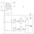
本第1実施形態に係る計量装置10(図2参照)は、図1に示すような歪みゲージ式ロードセル(以下、単に「ロードセル」と称する。)100を荷重センサとして採用するものである。このロードセル100は、ロバーバル型(またはダブルビーム型もしくは平衡ビーム型)と呼ばれる概略平行四辺形状の起歪体110と、この起歪体110の適宜の4箇所にある起歪部122〜128のそれぞれに貼着された互いに同一仕様の4個の歪みゲージ132〜138と、を有している。 The weighing device 10 (see FIG. 2) according to the first embodiment employs a strain gauge type load cell (hereinafter simply referred to as “load cell”) 100 as shown in FIG. 1 as a load sensor. The
具体的には、起歪体110の上側梁部112の2箇所に起歪部122および124が形成されている。そして、これら2箇所の起歪部122および124に1個ずつ歪みゲージ132および134が貼着されている。これら各歪みゲージ132および134は、上側梁部112の延伸方向に沿う中心線CL1上に配置されている。これと同様に、起歪体110の下側梁部114の2箇所に、詳しくは上側梁部112の各起歪部122および124と対向する当該2箇所に、起歪部126および128が形成されている。そして、これら2箇所の起歪部126および128に1個ずつ歪みゲージ136および138が貼着されている。これら各歪みゲージ136および138は、下側梁部114の延伸方向に沿う中心線CL2上に配置されている。なお、上側梁部112の一方端部と下側梁部114の一方端部とは、固定部116によって互いに結合されており、当該固定部116は、図示しない適当な固定部材を介して、計量装置10の図示しない基部に固定される。そして、上側梁部112の他方端部と下側梁部114の他方端部とは、可動部118によって互いに結合されており、当該可動部118には、図示しない適当な連結部材を介して、図示しない計量台が取り付けられる。 Specifically, strain-generating
各歪みゲージ132〜138は、図2に示す如く接続されることで、ホイートストンブリッジ回路20を形成している。即ち、圧縮歪みを検出する2個の歪みゲージ132および138が互いに対向すると共に、伸長歪みを検出する2個の歪みゲージ134および136が互いに対向するように、当該ブリッジ回路20が形成されている。このブリッジ回路20は、図示しない電源回路から例えば直流の電源電圧Viの供給を受け、その上で、起歪体110に印加されている荷重の大きさに比例した電圧の荷重信号Vo、厳密には当該荷重の大きさの変化量に比例した電圧変化量を示す荷重信号Vo、を出力する。なお、ブリッジ回路20(各歪みゲージ132〜138)の4つの接続点のうち互いに対向する一対の接続点が、当該ブリッジ回路20の電源入力端子であり、この電源入力端子に、電源電圧Viが供給される。そして、他の一対の接続点が、ブリッジ回路20の出力端子であり、この出力端子から、荷重信号Voが出力される。 The strain gauges 132 to 138 are connected as shown in FIG. 2 to form the
ブリッジ回路20から出力された荷重信号Voは、複数の、例えば2つの、増幅手段としての増幅回路32および34に入力される。これら各増幅回路32および34は、互いに同一仕様のものであり、例えば図3に示すような計装(インスツルメンテーション)アンプである。なお、この図3は、一方の増幅回路32の詳細な構成を示すものであるが、他方の増幅回路34についても、この図3と全く同じ構成をしており、従ってここでは、当該一方の増幅回路32の詳細な構成についてのみ、両者を代表して説明する。 The load signal Vo output from the
即ち、当該図3に示すように、増幅回路32は、2つの演算増幅器322および324を含む前段部分と、1つの演算増幅器326を含む後段部分と、を有している。このうちの前段部分を構成する各演算増幅器322および324の各非反転入力端子が増幅回路32全体としての入力端子とされ、これら各演算増幅器322および324の各非反転入力端子間にブリッジ回路20から荷重信号Voが入力される。そして、前段部分を構成する各演算増幅器322および324の各反転入力端子は、抵抗器328を介して、互いに接続されている。さらに、当該前段部分を構成する一方の演算増幅器322の反転入力端子と出力端子とは、帰還抵抗器330を介して、互いに接続されている。これと同様に、前段部分を構成する他方の演算増幅器324の反転入力端子と出力端子とは、別の帰還抵抗器332を介して、互いに接続されている。そして、前段部分を構成する一方の演算増幅器322の出力端子は、抵抗器334を介して、後段部分を構成する演算増幅器326の非反転入力端子に接続されている。また、前段部分を構成する他方の演算増幅器324の出力端子は、別の抵抗器336を介して、後段部分を構成する演算増幅器326の反転入力端子に接続されている。この後段部分を構成する演算増幅器326の非反転入力端子と出力端子とは、帰還抵抗器338を介して、互いに接続されている。そして、この後段部分を構成する演算増幅器326の反転入力端子は、別の抵抗器340を介して、後述するプリント配線板200の基準電位としての接地電位に接続されている。この後段部分を構成する演算増幅回路326の出力端子が増幅回路32全体としての出力端子であり、この出力端子から当該増幅回路32による増幅後の増幅後信号Wa1が出力される。 That is, as shown in FIG. 3, the
図2に戻って、一方の増幅回路32による増幅後の増幅後信号Wa1は、A/D変換回路42に入力され、ここでアナログ信号からデジタル信号Wd1に変換される。そして、このA/D変換回路42による変換後の言わばデジタル荷重信号Wd1は、加算手段としての加算回路50に入力される。これと同様に、他方の増幅回路32による増幅後の増幅後信号Wa2は、A/D変換回路42と同一仕様の別のA/D変換回路44に入力され、ここでアナログ信号からデジタル信号Wd2に変換される。そして、この別のA/D変換回路44による変換後のデジタル荷重信号Wd2もまた、加算回路50に入力される。 Returning to FIG. 2, the amplified signal Wa1 after amplification by one of the
加算回路50は、いわゆるデジタル加算回路であり、自身に入力される2つのデジタル荷重信号Wd1およびWd2を互いに加算する。そして、この加算回路50による加算後の加算後信号WAは、図示しない後段の回路に入力される。後段の回路は、加算後信号WAに基づいて、上述の起歪体110に印加されている荷重に含まれている図示しない被計量物の重量を求め、つまり重量測定値WNを求める。なお、加算手段50およびここで言う後段の回路は、例えば演算手段としてのCPU300によって構成されており、つまりそうなるように当該CPU300の動作を制御するためのプログラムが構成されている。そして、このCPU300と、上述の各増幅回路32および34と、各A/D変換回路42および44とは、プリント配線板200に搭載されている。また、上述した各ブリッジ22および24の電源電圧Viの供給源である電源回路も、当該プリント配線板200に搭載されている。 The
ところで、図3を参照しながら説明したように、一方の増幅回路32は、3つの演算増幅器322,324および326を含む計装アンプである。この増幅回路32に含まれている各演算増幅器322,324および326のそれぞれは、入力換算雑音という内部雑音を発生する。従って、これら各演算増幅器322,324および326を含む増幅回路32による増幅後信号Wa1には、当該各演算増幅器322,324および326それぞれの入力換算雑音が当該増幅回路32によって増幅された状態で重畳される。ここで例えば、この増幅回路32全体としての入力換算雑音の電圧成分がen’であり、また、ロードセル100(起歪体110)に或る大きさの荷重が印加されたときの当該増幅回路32の入力信号としての荷重信号Voの無負荷時からの電圧変化量がE’である、とする。この場合、増幅回路32全体としての入力換算雑音電圧en’に対する荷重信号Voの電圧変化量E’の比率、言わば増幅回路32の入力側のSN比(S/N_in’)は、上述の式1と同様、次の式3のように表される。 Incidentally, as described with reference to FIG. 3, one
《式3》
S/N_in’=E’/en’<<
S / N_in '= E' / en '
そして例えば、増幅回路32全体としての利得がG1である、とすると、当該増幅回路32の出力側のSN比(S/N_out’)は、上述の式2と同様、次の式4のように表される。 For example, assuming that the gain of the
《式4》
S/N_out’=(G1・E’)/(G1・en’)=E’/en’<<
S / N_out ′ = (G1 · E ′) / (G1 · en ′) = E ′ / en ′
これらの式3と式4とから分かるように、増幅回路32の出力側のSN比は、当該増幅回路32の入力側のSN比と等価(S/N_in’=S/N_out’)である。このことは、上述の式1と式2との関係と同様である。また、他方の増幅回路34についても、同様である。 As can be seen from these
この式4(または式3)によって表されるSN比は、加算回路50の入力側にも当て嵌まる。即ち、加算回路50に入力される一方のデジタル荷重信号Wd1の(一方の増幅回路32全体としての入力換算雑音に対する)SN比は、E’/en’である。これと同様に、当該加算回路50に入力される他方のデジタル荷重信号Wd2の(他方の増幅回路34全体としての入力換算雑音に対する)SN比もまた、E’/en’である。この加算回路50に入力される各デジタル荷重信号Wd1およびWd2そのもの(つまりE’に相当する成分)は、互いに相関するが、これらに含まれている各入力換算雑音(つまりen’に相当する成分)は、互いに無相関である。従って、これら各デジタル荷重信号Wd1およびWd2が加算回路50によって互いに加算された後の加算後信号WA(=Wd1+Wd2)には、当該各入力換算雑音が含まれているものの、この加算後信号WAに含まれる言わば総合的な入力換算雑音の特に電圧成分は、当該各入力換算雑音の電圧成分の単なる総和(=2・en’)ではなく、当該各入力換算雑音電圧の二乗和の平方根(=(2・en’2)1/2)として表される。即ち、加算後信号WAの(総合的な入力換算雑音に対する)SN比、言い換えれば加算回路50の出力側のSN比(S/N_add)は、次の式5のように表される。The S / N ratio represented by the equation 4 (or equation 3) is also applied to the input side of the
《式5》
S/N_add=(2・E’)/(2・en’2)1/2=21/2・(E’/en’)<< Formula 5 >>
S / N_add = (2 · E ′) / (2 · en ′2 )1/2 = 21/2 · (E ′ / en ′)
この式5から分かるように、加算回路50の出力側のSN比は、当該加算回路50の入力側のSN比の21/2(≒1.414)倍である。つまり例えば、各ブリッジ回路22および24に供給する電源電圧Viを大きくせずとも、SN比の高い加算後信号WAを得ることができ、ひいては安定した重量測定値WNを得ることができる。これは特に、静的秤において、その計量精度、つまり静的計量精度、を向上させるのに、大きく貢献する。As can be seen from Equation 5, the SN ratio on the output side of the
また、別の観点から言うと、例えば動的秤において、より定格容量の大きいロードセル100を採用することで、より高い動的計量精度を得ることができ、その際、ロードセル100の定格容量(の増大幅)を適宜に選定することで、上述の如く静的計量精度を向上させつつ、もしくは、少なくとも静的計量精度を低下させずに維持しつつ、当該より高い動的計量精度を得ることができる。即ち、より定格容量の大きいロードセル100を採用すると、式5(または式3もしくは式4)におけるE’が小さくなるため、当該式5で表される加算後信号WAのSN比が低下し、ひいては重量測定値WNの安定度が低下し、つまり静的計量精度が低下する。ただし、この静的計量精度を決定づける加算後信号WAのSN比については、ロードセル100の定格容量を適宜に選定することで、このロードセル100の定格容量を増大させる前の加算回路50の入力側のSN比よりも高くすることができ、もしくは、少なくとも当該ロードセル100の定格容量を増大させる前の加算回路50の入力側のSN比と同程度に維持することができる。この結果、静的計量精度の向上を図ることができ、もしくは、少なくとも当該静的計量精度を低下させずに維持することができる。その一方で、より定格容量の大きいロードセル100を採用すると、当該ロードセル100の固有振動数が大きくなる。これにより、ロードセル100(ブリッジ回路20)から出力される荷重信号Voに含まれる過渡応答振動の周波数が大きくなり、とりわけ、ロードセル100に荷重が印加された直後に現れる振幅の大きなオーバシュート状の当該過渡応答振動が収束するのに掛かる時間が短縮化される。加えて、この過渡応答振動をフィルタ回路によって減衰させる場合には、応答性の高い(応答遅れの小さい)フィルタ回路を採用することができ、つまり当該過渡応答振動を高速で減衰させることができる。従って、より高い動的計量精度を得ることができ、つまりはより高速計量に適した性能を呈することができる。なお、動的秤においても、スパン調整等のための事前の調整作業時に(計量台上に被計量物を含む何らの物品も載置されていない無負荷状態(空掛け状態)または当該計量台上に既知の重量の分銅が載置された状態で)静的計量が行われる。ゆえに、動的秤にとっても、動的計量精度の向上のみならず、静的計量精度の向上(または維持)を図ることは、非常に重要である。 From another viewpoint, for example, in a dynamic balance, by adopting a
このように本第1実施形態によれば、より高い静的計量精度を得ることができ、または、より高い動的計量精度を得ることができる。即ち、本発明は、静的秤および動的秤のいずれにも適用することができ、いずれの用途においても、高い計量精度を得ることができる。 Thus, according to the first embodiment, higher static weighing accuracy can be obtained, or higher dynamic weighing accuracy can be obtained. That is, the present invention can be applied to both a static balance and a dynamic balance, and high weighing accuracy can be obtained in any application.
なお、本第1実施形態においては、一方の増幅回路32について、図3に示したような計装アンプとし、他方の増幅回路34についても、同様の計装アンプとしたが、これに限らない。これらの増幅回路32および34については、演算増幅器を用いるものであればよく、例えば差動増幅回路であってもよく、好ましくは高入力インピーダンス型のものが適当であり、極端には利得が1(G1=1およびG2=1)であるボルテージフォロワであってもよい。 In the first embodiment, one
また、本第1実施形態においては、各増幅回路32および34による増幅後の各増幅後信号Wa1およびWa2がアナログ信号からデジタル信号Wd1およびWd2に変換された後に、これら各デジタル荷重信号Wd1およびWd2が互いに加算される構成としたが、これに限らない。例えば、図4に示すようなアナログ加算回路60によって、当該各増幅回路32および34による増幅後の各増幅後信号Wa1およびWa2が互いに加算される構成としてもよい。 In the first embodiment, the amplified signals Wa1 and Wa2 after being amplified by the
即ち、図4に示すアナログ加算回路60によれば、各増幅回路32および34による増幅後の各増幅後信号Wa1およびWa2は、互いに別個の抵抗器602および604を介して、演算増幅器606の反転入力端子に入力される。なお、この演算増幅器606の非反転入力端子は、接地電位に接続されている。さらに、この演算増幅器606の反転入力端子は、帰還抵抗器608を介して、当該演算増幅器606の出力端子に接続されている。この演算増幅器606の出力端子が、アナログ加算回路60全体としての出力端子であり、この出力端子から、当該アナログ加算回路60による加算後の加算後信号WA’(=Wa1+Wa2)が出力される。そして、図示は省略するが、この加算後信号WA’は、A/D変換回路によってアナログ信号からデジタル信号に変換され、この変換後のデジタル加算後信号に基づいて、被計量物の重量が求められ、つまり重量測定値WNが求められる。 That is, according to the
この図4に示す構成によっても、図2に示した構成と同様、アナログ加算回路60の出力側のSN比、つまり加算後信号WA’のSN比は、当該アナログ加算回路60の入力側のSN比、つまり各増幅後信号Wa1およびWa2それぞれのSN比、の21/2倍となる。即ち、SN比の高い加算後信号WA’が得られ、ひいては安定した重量測定値WNが得られ、つまり静的計量精度の向上が図られる。また、別の観点から言えば、特に動的秤において、より定格容量の大きいロードセル100を採用することで、高い静的計量精度を維持しつつ、より高い動的計量精度を得ることができ、つまりはより高速計量に適した性能を呈することができる。なお、アナログ加算回路60による加算後の加算後信号WA’は、図示しないA/D変換回路によってアナログ信号からデジタル信号に変換される。そして、このA/D変換回路による変化後のデジタル加算後信号に基づいて、重量測定値WNが求められる。4, the SN ratio on the output side of the
さらに、本第1実施形態においては、2つの増幅回路32および34が設けられる構成を例示したが、3つ以上の増幅回路が設けられてもよい。この場合も、各増幅回路による増幅後の各増幅後信号は、例えば図2に示した構成と同様にアナログ信号からデジタル信号に変換された後に互いに加算され、または、図4に示した構成と同様にアナログ信号の状態で互いに加算される。このように3つ以上の増幅回路が設けられることによって、言い換えれば当該増幅回路の数が多いほど、よりSN比の高い加算後信号WA(またはWA’)が得られ、ひいては静的計量精度のさらなる向上が図られ、または、動的計量精度のさらなる向上が図られる。 Furthermore, in the first embodiment, the configuration in which the two
加えて、本第1実施形態においては、ブリッジ回路20に供給される電源電圧Viを直流としたが、交流としてもよい。この場合、ブリッジ回路20から出力される荷重信号Voもまた交流になるので、特にこの交流の荷重信号Voが入力される各増幅回路32および34については、当該荷重信号Voの態様に応じた構成とする必要がある。 In addition, in the first embodiment, the power supply voltage Vi supplied to the
次に、本発明の第2実施形態について、図5および図6を参照して説明する。 Next, a second embodiment of the present invention will be described with reference to FIGS.
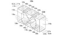
本第2実施形態に係る計量装置10a(図6参照)は、図5に示すようなロードセル100aを備えている。このロードセル100aは、図1に示した第1実施形態におけるのと同様のロバーバル型の起歪体110aと、この起歪体110aの4箇所の起歪部122a〜128aに適宜に貼着された互いに同一仕様の合計8個の歪みゲージ132a〜138aおよび142a〜148aと、を有している。 The weighing
具体的には、起歪体110aの上側梁部112aに形成されている2箇所の起歪部122aおよび124bの一方122aに、2個の歪みゲージ132aおよび142aが貼着されており、他方の起歪部124aに、2個の歪みゲージ134aおよび144aが貼着されている。ここで、一方の起歪部122aに貼着されている2個の歪みゲージ132aおよび142aは、上側梁部112aの延伸方向に沿う中心線CL1aに関して互いに対称を成すように配置されており、他方の起歪部124aに貼着されている2個の歪みゲージ134aおよび144aもまた、当該中心線CL1aに関して互いに対称を成すように配置されている。さらに、中心軸CL1aの両横方の一方にある2個の歪みゲージ132aおよび134aは、当該中心軸CL1aに平行な直線L11a上に配置されており、当該両横方の他方にある2個の歪みゲージ142aおよび144aは、当該中心軸CL1aに関して直線L11aと対称を成す別の直線L12a上に配置されている。これと同様に、起歪体110aの下側梁部114aに形成されている2箇所の起歪部126aおよび128aの一方126aに、2個の歪みゲージ136aおよび146aが貼着されており、他方の起歪部128aに、2個の歪みゲージ138aおよび148aが貼着されている。ここで、一方の起歪部126aに貼着されている2個の歪みゲージ136aおよび146aは、下側梁部114aの延伸方向に沿う中心線CL2aに関して互いに対称を成すように配置されており、他方の起歪部128aに貼着されている2個の歪みゲージ138aおよび148aもまた、当該中心線CL2aに関して互いに対称を成すように配置されている。さらに、中心軸CL2aの両横方の一方にある2個の歪みゲージ136aおよび138aは、当該中心軸CL2aに平行な直線L21a上に配置されており、当該両横方の他方にある2個の歪みゲージ146aおよび148aは、当該中心軸CL2aに関して直線L21aと対称を成す別の直線L22a上に配置されている。なお、起歪体110aの固定部116aおよび可動部118aについては、図1に示した第1実施形態のものと同様であるので、それらの説明は省略する。 Specifically, two
このロードセル110aを構成する合計8個の歪みゲージ132a〜138aおよび142a〜148aのうち、上側梁部112aの一方の直線L11a上に配置された2個の歪みゲージ132aおよび134aと、下側梁部114aの一方の直線L21a上に配置された2個の歪みゲージ136aおよび138aと、の計4個の歪みゲージ132a〜138aは、図6に示す如く接続されることで、ホイートストンブリッジ回路22aを形成している。即ち、圧縮歪みを検出する2個の歪みゲージ132aおよび138aが互いに対向すると共に、伸長歪みを検出する2個の歪みゲージ134aおよび136aが互いに対向するように、当該ブリッジ回路22aが形成されている。そして、上側梁部112aの他方の直線L12a上に配置された2個の歪みゲージ142aおよび144aと、下側梁部114aの他方の直線L22a上に配置された2個の歪みゲージ146aおよび148aと、の残りの計4個の歪みゲージ142a〜148aもまた、図6に示す如く接続されることで、別のホイートストンブリッジ回路24aを形成している。即ち、圧縮歪みを検出する2個の歪みゲージ142aおよび148aが互いに対向すると共に、伸長歪みを検出する2個の歪みゲージ144aおよび146aが互いに対向するように、当該ブリッジ回路24aが形成されている。 Out of a total of eight
これら各ブリッジ回路22aおよび24aは、互いに共通の図示しない電源回路から例えば直流の電源電圧Viの供給を受ける。その上で、これら各ブリッジ回路22aおよび24aは、起歪体110aに印加されている荷重の大きさに比例した電圧の荷重信号Vo1およびVo2を出力し、厳密には当該荷重の大きさの変化量に比例した電圧変化量を示す荷重信号Vo1およびVo2を出力する。 Each of the
各ブリッジ回路22aおよび24aから出力された各荷重信号Vo1およびVo2は、当該各ブリッジ回路22aおよび24aと1対1の関係で対応付けられた2つの増幅回路32aおよび34aに個別に入力される。各増幅回路32aおよび34aは、互いに同一仕様のものであり、例えば第1実施形態における各増幅回路32および34と同様の計装アンプである。そして、これら各増幅回路32aおよび34aは、それぞれに入力される各荷重信号Vo1およびVo2を互いに同じ利得G1およびG2で増幅する。 The load signals Vo1 and Vo2 output from the
さらに、一方の増幅回路32aによる増幅後の信号Wa1は、A/D変換回路42aに入力され、ここでアナログ信号からデジタル信号Wd1に変換される。これと同様に、他方の増幅回路34aによる増幅後の信号Wa2は、当該A/D変換回路42aと同一仕様の別のA/D変換回路44aに入力され、ここでアナログ信号からデジタル信号Wd2に変換される。 Further, the signal Wa1 amplified by one
そして、一方のA/D変換回路42aによる変換後のデジタル荷重信号Wd1は、フィルタ手段としてのフィルタ回路52aに入力され、ここで当該デジタル荷重信号Wd1に含まれている比較的に周波数の低い機械的要因による振動成分を減衰させるためのフィルタリング処理を施される。これと同様に、他方のA/D変換回路44aによる変換後のデジタル荷重信号Wd2は、当該フィルタ回路52aと同一仕様の別のフィルタ回路54aに入力され、ここで当該フィルタ回路52aによるのと同様のフィルタリング処理を施される。 Then, the digital load signal Wd1 after conversion by one A /
一方のフィルタ回路52aによるフィルタリング処理後の信号Wf1は、初期成分排除手段としての減算回路62aに入力される。この減算回路62aには、図示しないメモリ回路から初期荷重信号Wi1も入力される。ここで、初期荷重信号Wi1とは、上述の計量台や連結部材の重量等の最初からロードセル100a(起歪体110a)に印加されている初期荷重に相当する信号であり、例えば計量台に被計量物を含む何らの物品も載置されていない無負荷状態(空掛け状態)にあるときのフィルタリング処理後信号Wf1が当該初期荷重信号Wi1としてメモリ回路に記憶される。また、このように計量台が無負荷状態にあるときのフィルタリング処理後信号Wf1が初期荷重信号Wi1とされることで、当該初期荷重信号Wi1には、一方のブリッジ回路22aを形成する各歪みゲージ132a〜138dの抵抗値のバラツキ等に起因する不平衡成分も含まれることになる。減算回路62aは、この初期荷重信号Wi1をフィルタリング処理後信号Wf1から差し引くことで、被計量物の重量のみに応じた、言い換えれば当該被計量物が計量台に載置されたときのフィルタリング処理後信号Wf1の変化量に応じた、言わば正味の荷重信号Wb1を出力する。この正味荷重信号Wb1は、次の式6のように表される。 The signal Wf1 after the filtering process by one
《式6》
Wb1=Wf1−Wi1<< Formula 6 >>
Wb1 = Wf1-Wi1
これと同様に、他方のフィルタ回路54aによるフィルタリング処理後の信号Wf2は、別の減算回路64aに入力される。そして、この減算回路64aにも、メモリ回路から初期荷重信号Wi2が入力される。この減算回路64aに入力される初期荷重信号Wi2は、例えば計量台が無負荷状態にあるときのフィルタリング処理後信号Wf2がメモリ回路に記憶されたものである。減算回路64aは、この初期荷重信号Wi2をフィルタリング処理後信号Wf2から差し引くことで、被計量物の重量のみに応じた正味荷重信号Wb2を出力する。この正味荷重信号Wb2は、次の式7のように表される。 Similarly, the signal Wf2 after the filtering process by the
《式7》
Wb2=Wf2−Wi1<< Formula 7 >>
Wb2 = Wf2-Wi1
さらに、上述の式6に基づく一方の正味荷重信号Wb1は、スパン調整手段としての乗算回路72aに入力され、ここでスパン係数k1を乗ぜられる。このスパン係数k1は、事前の調整作業で定められ、詳しくは計量台にMという既知の重量を持つ分銅が載置された状態で次の式8が成立するように調整される。なお、分銅の重量Mは、例えば計量装置10aの秤量Wmと等価(M=Wm)である。 Further, one net load signal Wb1 based on the above-described equation 6 is input to a
《式8》
k1・Wb1=M<< Formula 8 >>
k1 · Wb1 = M
これと同様に、式7に基づく他方の正味荷重信号Wb2は、別の乗算回路74aに入力され、ここで別のスパン係数k2を乗ぜられる。このスパン係数k2もまた、事前の調整作業で定められ、詳しくは計量台に重量Mの分銅が載置された状態で次の式9が成立するように調整される。 Similarly, the other net load signal Wb2 based on Equation 7 is input to another
《式9》
k2・Wb2=M<< Formula 9 >>
k2 · Wb2 = M
そして、一方の乗算回路72aによるスパン調整処理後の信号Ws1(=k1・Wb1)は、上述とは別の零点調整手段としての減算回路82aに入力される。この減算回路82aには、上述のメモリ回路から零点調整信号Wz1も入力される。ここで、零点調整信号Wz1とは、当該一方のスパン調整処理後信号Ws1の零点が変動し、ひいては後述する重量測定値WNの零点が変動したときに、この零点を正常な状態に戻すための信号であり、後述するように、当該零点調整信号Wz1は、図示しない操作手段としての操作キーによって零点調整操作が行われたときに更新される。減算回路82aは、この零点調整信号Wz1を一方のスパン調整処理後信号Ws1から差し引くことで、零点調整処理後の信号Wn1を出力する。この零点調整処理後信号Wn1は、次の式10のように表される。 The signal Ws1 (= k1 · Wb1) after the span adjustment processing by one
《式10》
Wn1=Ws1−Wz1 where Ws1=k1・Wb1<<
Wn1 = Ws1-Wz1 where Ws1 = k1 · Wb1
これと同様に、他方の乗算回路74aによるスパン調整処理後の信号Ws2(=k2・Wb2)は、別の減算回路84aに入力される。そして、この減算回路84aにも、メモリ回路から零点調整信号Wz2が入力される。この減算回路84aに入力される零点調整信号Wz2もまた、後述するように、操作キーによって零点調整操作が行われたときに更新される。減算回路84aは、この零点調整信号Wz2を他方のスパン調整処理後信号Ws2から差し引くことで、零点調整処理後の信号Wn2を出力する。この零点調整処理後信号Wn2は、次の式11のように表される。 Similarly, the signal Ws2 (= k2 · Wb2) after the span adjustment processing by the
《式11》
Wn2=Ws2−Wz2 where Ws2=k2・Wb2<< Formula 11 >>
Wn2 = Ws2-Wz2 where Ws2 = k2 · Wb2
なお、上述の操作キーによって零点調整操作が行われると、そのときの一方の零点調整処理後信号Wn1と一方の零点調整信号Wz1とが互いに加算された信号(=Wn1+Wz1)が、新たな当該一方の零点調整信号Wz1としてメモリ回路に記憶される。即ち、次の式12に基づいて、当該一方の零点調整信号Wz1が更新される。そして、この更新後の一方の零点調整信号Wz1が上述の式10に適用されることで、一方の零点調整処理後信号Wn1がWn1=0となり、つまり一方のスパン調整処理後信号Ws1の零点変動が補償され、適切な零点調整処理が行われる。 When the zero adjustment operation is performed by the above-described operation key, a signal (= Wn1 + Wz1) obtained by adding one zero-adjustment-processed signal Wn1 and one zero-adjustment signal Wz1 to each other is a new one. Is stored in the memory circuit as a zero adjustment signal Wz1. That is, based on the following equation 12, the one zero adjustment signal Wz1 is updated. Then, the one zero-point adjustment signal Wz1 after the update is applied to the above-described
《式12》
Wn1+Wz1→Wz1<< Formula 12 >>
Wn1 + Wz1 → Wz1
これと同様に、操作キーによって零点調整操作が行われると、そのときの他方の零点調整処理後信号Wn2と他方の零点調整信号Wz2とが互いに加算された信号(=Wn2+Wz2)が、新たな当該他方の零点調整信号Wz2としてメモリ回路に記憶される。即ち、次の式13に基づいて、当該他方の零点調整信号Wz2が更新される。そして、この更新後の一方の零点調整信号Wz2が上述の式11に適用されることで、他方の零点調整処理後信号Wn2がWn2=0となり、つまり他方のスパン調整処理後信号Ws2の零点変動が補償され、適切な零点調整処理が行われる。なお、操作キーによって零点調整操作が行われるときには、計量台が無負荷状態にあることが、肝要である。また、計量台が無負荷状態にあることが自動的に検出されて当該零点調整処理が自動的に行われる、いわゆる自動零点調整機能が、設けられてもよい。 Similarly, when the zero adjustment operation is performed with the operation key, a signal (= Wn2 + Wz2) obtained by adding the other zero adjustment signal Wn2 and the other zero adjustment signal Wz2 to each other at that time is a new one. The other zero adjustment signal Wz2 is stored in the memory circuit. That is, based on the following equation 13, the other zero adjustment signal Wz2 is updated. Then, the one zero adjustment signal Wz2 after the update is applied to the above-described equation 11, so that the other zero adjustment signal Wn2 becomes Wn2 = 0, that is, the zero fluctuation of the other span adjustment signal Ws2 occurs. Are compensated, and an appropriate zero adjustment process is performed. When the zero adjustment operation is performed by the operation key, it is important that the weighing platform is in an unloaded state. In addition, a so-called automatic zero adjustment function may be provided in which it is automatically detected that the weighing platform is in an unloaded state and the zero adjustment process is automatically performed.
《式13》
Wn2+Wz2→Wz2<< Formula 13 >>
Wn2 + Wz2 → Wz2
これら2つの零点調整処理後信号Wn1およびWn2は、加算手段としての加算回路90aに入力され、ここで互いに加算される。そして、この加算回路90aによる加算後の加算後信号WA(=Wn1+Wn2)は、上述とは別の総合スパン調整手段としての乗算回路92aに入力され、ここで上述とは別のスパン係数Kを乗ぜられる。この言わば総合的なスパン係数Kもまた、事前の調整作業で定められ、詳しくは計量台に上述の重量Mの分銅が載置された状態で次の式14が成立するように調整される。なお、この総合的なスパン係数Kが乗ぜられる加算後信号WAは、上述の如く計量台に重量Mの分銅が載置された状態で調整された個別のスパン係数k1およびk2を含んでいることから、当該総合的なスパン係数Kは、理想的にはK=1/2となる。 These two zero point adjusted post-processing signals Wn1 and Wn2 are input to an adding
《式14》
K・WA=M where WA=Wn1+Wn2<< Formula 14 >>
K.WA = M where WA = Wn1 + Wn2
そして、この総合的なスパン係数Kが乗ぜられた後の言わば総合スパン調整後信号(=K・WA)に基づいて、詳しくは次の式15に基づいて、被計量物の重量を表す重量測定値WNが求められる。この重量測定値WNは、例えば図示しない情報出力手段としてのディスプレイに表示される。 Then, based on the so-called overall span adjusted signal (= K · WA) after being multiplied by the overall span coefficient K, specifically, based on the following equation 15, a weight measurement representing the weight of the object to be weighed. A value WN is determined. The weight measurement value WN is displayed, for example, on a display as information output means (not shown).
《式15》
WN=K・WA<< Formula 15 >>
WN = K ・ WA
併せて、上述の2つの零点調整処理後信号Wn1およびWn2は、相互差演算手段としての相互差演算回路94aに入力される。この相互差演算回路94aは、次の式16に基づいて、これら2つの零点調整処理後信号Wn1およびWn2の相互差の絶対値|WD|を求める。この相互差絶対値|WD|は、スパン異常判定手段としての図示しないスパン異常判定回路に入力される。 In addition, the above-described two zero-adjustment processed signals Wn1 and Wn2 are input to a mutual
《式16》
|WD|=|Wn1−Wn2|<< Formula 16 >>
| WD | = | Wn1-Wn2 |
なお、フィルタ手段としての各フィルタ回路52aおよび54aと、初期零点設定手段としての各減算回路62aおよび64aと、スパン調整手段としての各乗算回路72aおよび74aと、零点調整手段としての各減算回路82aおよび84aと、加算手段としての加算回路90aと、総合スパン調整手段としての乗算回路92aと、相互差演算手段としての相互差演算回路94aとは、例えばCPU300aによって構成されており、つまりそうなるように当該CPU300aの動作を制御するためのプログラムが構成されている。また、スパン異常判定回路も、CPU300aによって構成されている。さらに、このCPU300aと、上述の各増幅回路32aおよび34aと、各A/D変換回路42aおよび44aとは、プリント配線板200aに搭載されている。また、各ブリッジ回路22aおよび24aの電源電圧Viの供給源である上述の電源回路も、当該プリント配線板200aに搭載されている。 Each
スパン異常判定回路(CPU300a)は、上述の相互差絶対値|WD|に基づいて、ロードセル100aにスパン異常が発生していないかどうかを判定し、言わば当該ロードセル100についてのスパン異常検出を行う。即ち、相互差絶対値|WD|は、理想的にはゼロ(|WD|=0)であり、詳しくはロードセル100aが正常であるときにはゼロであるのが理想である。そして、各ブリッジ回路22aおよび24aを形成する各歪みゲージ132a〜138aおよび142a〜148aのいずれかに物質変化が生じたり、或いは、当該各歪みゲージ132a〜138aおよび142a〜148aが貼着されている起歪体110aの各起歪部122a〜128aのいずれかに腐食が生じたりすると、各ブリッジ回路22aおよび24aから出力される各荷重信号Vo1およびVo2の一方にスパン変化が生じ、または、当該各荷重信号Vo1およびVo2の両方に互いに異なるスパン変動が生じ、これにより、相互差絶対値|WD|がゼロではなくなる(|WD|≠0)。そこで、スパン異常判定回路は、この相互差絶対値|WD|が過度に大きくなったときに、ロードセル100aのスパンが過度に変動したものと判定し、つまり当該ロードセル100aにスパン異常が発生したものと判定する。ただし、相互差絶対値|WD|は、被計量物の重量の大小によって変わり、例えば当該被計量物の重量が大きいほど大きく、当該被計量物の重量が小さいほど小さい。このことを勘案して、異常判定回路は、被計量物の重量に対する相互差絶対値|WD|の比率、厳密には重量測定値WNに対する当該相互差絶対値|WD|の比率|WD|/WN、を評価パラメータとし、この比率|WD|/WNと所定のしきい値αとを比較する。そして、当該比率|WD|/WNがしきい値αよりも大きいときに、つまり次の式17が満足されるときに、ロードセル100にスパン異常が発生したものと判定し、そうでないときには、スパン異常は発生していないものと判定する。なお、ここで言うしきい値αは、上述の操作キーによって適宜に設定される。 The span abnormality determination circuit (
《式17》
|WD|/WN>α<Equation 17>
| WD | / WN> α
その一方で、重量測定値WNが過度に小さいと、この式17における比率|WD|/WNに誤差が生じ易くなり、ひいては誤ったスパン異常検出が行われる虞がある。これを回避するべく、重量測定値WNが或る程度の大きさであることを条件に、詳しくは次の式18が満足されることを条件に、スパン異常検出が行われる。なお、この式18におけるβは、0よりも大きく、かつ、計量装置10aの秤量Wmよりも小さい値(0<β<Wm)であり、操作キーの操作によって例えばWm/5〜Wm/3程度の値に設定される。 On the other hand, if the weight measurement value WN is excessively small, an error is likely to occur in the ratio | WD | / WN in the equation 17, and there is a possibility that erroneous span abnormality detection is performed. In order to avoid this, the span abnormality detection is performed on the condition that the weight measurement value WN is a certain size, and specifically, on the condition that the following Expression 18 is satisfied. Note that β in the equation 18 is a value larger than 0 and smaller than the weight Wm of the weighing
《式18》
WN>β<< Formula 18 >>
WN> β
このスパン異常検出機能によってロードセル100aにスパン異常が発生したことが検出されると、その旨を表す情報、例えばアラームが、上述のディスプレイに表示される。従って、このディスプレイのアラーム表示から、ロードセル100aにスパン異常が発生しているかどうかを認識することができる。 When it is detected by the span abnormality detection function that a span abnormality has occurred in the
併せて、上述の各零点調整処理後信号Wn1およびWn2についても、厳密にはこれら各零点調整処理後信号Wn1およびWn2のそれぞれが重量値に変換された言わば零点調整処理後重量値についても、ディスプレイに表示される。これにより例えば、ロードセル100aにスパン異常が発生したときに、このスパン異常が一方のブリッジ回路22aに発生したのか、厳密には当該スパン異常が一方のブリッジ回路22aから一方の減算回路82aまでの間の言わば一方の信号処理系統に発生したのか、それとも、当該スパン異常が他方のブリッジ回路24aに発生したのか、厳密には当該スパン異常が他方のブリッジ回路24aから他方の減算回路84aまでの間の言わば他方の信号処理系統に発生したのかを、認識することができる。例えば、一方の信号処理系統にスパン異常が発生したときには、当該一方の信号処理系統の零点調整処理後信号Wn1に従う零点調整処理後重量値が(そのときの被計量物の重量とは懸け離れた)異常な値となる。これと同様に、他方の信号処理系統にスパン異常が発生したときには、当該他方の信号処理系統の零点調整処理後信号Wn2に従う零点調整処理後重量値が異常値となる。 In addition, for each of the above-described zero-adjusted signals Wn1 and Wn2, strictly speaking, each of these zero-adjusted signals Wn1 and Wn2 is also converted to a weight value. Is displayed. Thereby, for example, when a span abnormality occurs in the
また上述したように、各零点調整信号Wz1およびWz2については、式12および式13の如く更新されるが、この更新が行われるたびに、各信号処理系統(各スパン調整処理後信号Ws1およびWs2)それぞれの零点変動量が蓄積されたものとなる。従って例えば、各信号処理系統のいずれかに過度な零点変動が生じた場合には、この零点変動の蓄積量である各零点調整信号Wz1およびWz2のうちの当該過度な零点変動が生じた側のものが異常な態様となる。そこで、これら各零点調整信号Wz1およびWz2のそれぞれと所定のしきい値γとが比較され、この比較結果に基づいて、各信号処理系統のそれぞれに過度な零点変動が生じていないかどうかの判定が行われ、つまり零点異常検出が行われる。具体的には、次の式19が満足されるときに、一方の信号処理系統に零点異常が生じているものと判定される。そして、式20が満足されるときに、他方の信号処理系統に零点異常が生じているものと判定される。この判定結果もまた、ディスプレイに表示される。そして、ここで言うしきい値γもまた、操作キーの操作によって適宜に設定される。 Further, as described above, the zero point adjustment signals Wz1 and Wz2 are updated as shown in Expressions 12 and 13, but each time this update is performed, each signal processing system (each span adjustment processed signal Ws1 and Ws2 is updated). ) Each zero point variation is accumulated. Therefore, for example, when an excessive zero point fluctuation occurs in any one of the signal processing systems, the zero point adjustment signals Wz1 and Wz2, which are accumulated amounts of the zero point fluctuations, on the side where the excessive zero point fluctuation occurs. Things become abnormal. Therefore, each of these zero point adjustment signals Wz1 and Wz2 is compared with a predetermined threshold value γ, and based on the comparison result, it is determined whether or not excessive zero point fluctuations have occurred in each of the signal processing systems. In other words, zero point abnormality detection is performed. Specifically, when the following expression 19 is satisfied, it is determined that a zero point abnormality has occurred in one of the signal processing systems. When
《式19》
|Wz1|>γ<Formula 19>
| Wz1 |> γ
《式20》
|Wz2|>γ<<
| Wz2 |> γ
なお、これら式19および式20の両方が満足される場合であっても、つまり各信号処理系統の両方に零点異常が生じている場合であって、これら各零点が互いに反対の方向に変動している場合には、上述の式16で表される相互差絶対値|WD|が過度に大きくならず、ひいては上述の式17が満足されないことがある。即ち、式17のみからでは精確なスパン異常検出が実現されないことがある。従って、式17に基づくスパン異常検出のみならず、これら式19および式20に基づく零点異常検出が行われることによって、より精確な当該スパン異常検出が実現され、ひいてはこれらスパン異常検出および零点異常検出を含む言わば総合的な異常検出が実現される。因みに、零点異常検出もまた、CPU300aによって実現される。即ち、CPU300aは、言わば零点異常検出手段としても機能する。 Even when both of these
そして、各信号処理系統のいずれかに異常(スパン異常または零点異常)が発生した場合には、当該異常が発生していない正常な信号処理系統の零点調整処理後信号Wn1またはWn2のみに基づいて、重量測定値WNが求められる。例えば、一方の信号処理系統に異常が発生した場合には、他方の信号処理系統の零点調整処理後信号Wn2を用いた次の式21に基づいて、重量測定値WNが求められる。これとは反対に、他方の信号処理系統に異常が発生した場合には、一方の信号処理系統の零点調整処理後信号Wn1を用いた式22に基づいて、重量測定値WNが求められる。なお、これらの式21および式22における総合スパン係数Kは、K=1である。 When an abnormality (span abnormality or zero point abnormality) occurs in any of the signal processing systems, based on only the signal Wn1 or Wn2 after the zero point adjustment processing of the normal signal processing system in which the abnormality does not occur The weight measurement value WN is determined. For example, when an abnormality occurs in one signal processing system, the weight measurement value WN is obtained based on the following equation 21 using the zero-adjusted signal Wn2 of the other signal processing system. On the other hand, when an abnormality occurs in the other signal processing system, the weight measurement value WN is obtained based on Expression 22 using the zero adjustment signal Wn1 of one signal processing system. Note that the total span coefficient K in these equations 21 and 22 is K = 1.
《式21》
WN=K・Wn2<< Formula 21 >>
WN = K · Wn2
《式22》
WN=K・Wn1<< Formula 22 >>
WN = K · Wn1
ところで、本第2実施形態においても、上述の第1実施形態と同様、各増幅回路32aおよび34aのそれぞれは、3つの演算増幅器を含む計装アンプである。従って、これら各増幅回路32aおよび34aによる増幅後の各増幅後信号Wa1およびWa2のそれぞれには、当該3つの演算増幅器それぞれの入力換算雑音が重畳した状態にある。具体的には、各増幅後信号Wa1およびWa2それぞれのSN比は、上述の式4の如くE’/en’である。そして、このSN比は、加算回路90aの入力側にも当て嵌まる。即ち、加算回路90aの入力側のSN比もまた、E’/en’である。ただし、加算回路90aの出力側のSN比は、上述の式5の如く21/2・(E’/en’)であり、つまり当該加算回路90aの入力側のSN比の21/2倍である。即ち、SN比の高い加算後信号WAを得ることができ、ひいては安定した重量測定値WNを得ることができ、つまり静的計量精度の向上を図ることができる。また、別の観点から言えば、特に動的秤において、より定格容量の大きいロードセル100aを採用することで、高い静的計量精度を維持しつつ、より高い動的計量精度を得ることができ、つまりはより高速計量に適した性能を呈することができる。とりわけ、各フィルタ回路52aおよび54aによって上述した過渡応答振動を減衰させる場合には、当該フィルタ回路52aおよび54aとして応答性の高い(応答遅れの小さい)ものを採用することができ、これもまた、動的計量精度の向上に大きく貢献し、つまりは高速計量の実現に好都合である。By the way, also in the second embodiment, each of the
このように本第2実施形態においても、第1実施形態と同様、より高い静的計量精度を得ることができ、または、より高い動的計量精度を得ることができる。即ち、静的秤および動的秤のいずれの用途においても、高い計量精度を得ることができる。 As described above, also in the second embodiment, higher static weighing accuracy can be obtained or higher dynamic weighing accuracy can be obtained as in the first embodiment. That is, high weighing accuracy can be obtained in any application of the static balance and the dynamic balance.
さらに本第2実施形態によれば、ロードセル100aについての異常検出機能が設けられており、詳しくはスパン異常検出機能および零点異常検出機能が設けられている。このうちのスパン異常検出機能については、上述の式16の相互差絶対値|WD|に基づいて、つまり上述した2つの信号処理系統のそれぞれに独立して初期成分排除処理,スパン調整処理および零点調整処理が施された後の信号(零点調整処理後信号)Wn1およびWn2に基づいて、当該スパン異常の有無が判定される。そして、零点異常検出機能については、上述の式19および式20に示す如く当該2つの信号処理系統のそれぞれにおける零点変動の蓄積量である各零点調整信号Wz1およびWz2に基づいて、つまりはそれぞれの信号処理系統ごとに独立して初期成分排除処理,スパン調整処理および零点調整処理が施された後の信号Wn1およびWn2に基づいて、零点異常の有無が判定される。また、この異常検出機能が加わることで、スパン異常検出機能がより精確なものとなる。従って例えば、上述した各ブリッジ回路22aおよび24aの不平衡成分や正常な範囲内での温度ドリフト,零点変動等があるとしても、これらの影響が排除された上で、スパン異常検出および零点異常検出を含む精確な異常検出を実現することができる。 Furthermore, according to the second embodiment, an abnormality detection function for the
加えて、本第2実施形態によれば、起歪体110a各起歪部122a〜128aのそれぞれに、つまり互いに近接した位置に、2個ずつ歪みゲージ132a〜138aおよび142a〜148aが貼着されている。従って例えば、計量台上に被計量物が偏在することによって起歪体110aに捻りが発生し、これにより、各起歪部122a〜128aの一部または全部において歪み(応力)の分布にバラツキが生じたとしても、これら各起歪部122a〜128aのそれぞれの歪は2個の歪みゲージによって言わば平均化された状態で検出される。ゆえに、このような歪みの分布のバラツキが生じることによる影響が低減され、ひいてはより精確な重量測定値WNが得られ、つまり高い計量精度が得られる。特に動的秤等の高速計量が要求される用途においては、このような歪みの分布のバラツキが生じ易いので、その影響が低減される本第2実施形態の構成は、極めて有益である。 In addition, according to the second embodiment, two
なお、本第2実施形態においては、起歪体110aの上側梁部112aの一方の直線L11a上に配置された2個の歪みゲージ132aおよび134aと、下側梁部114aの一方の直線L21a上に配置された2個の歪みゲージ136aおよび138aと、の組合せによって、一方のブリッジ回路22aが形成され、残りの4個の歪みゲージ142a〜148aの組合せによって、他方のブリッジ回路24aが形成されたが、これに限らない。例えば、上側梁部112aの一方の直線L11a上に配置された2個の歪みゲージ132aおよび134aと、下側梁部114aの他方の直線L22a上に配置された2個の歪みゲージ146aおよび148aと、の組合せによって、一方のブリッジ回路22aが形成され、残りの4個の歪みゲージ136a,138a,142aおよび144aの組合せによって、他方のブリッジ24aが形成されてもよい。勿論、これ以外の組合せによって、各ブリッジ回路22aおよび24aが形成されてもよい。 In the second embodiment, two
また、本第2実施形態においても、例えば図4に示したのと同様のアナログ加算回路によって、各増幅回路32aおよび34aによる各増幅後信号Wa1およびWa2が互いに加算される構成としてもよい。この構成によれば、図示は省略するが、アナログ加算回路による加算後の加算後信号WA’は、A/D変換回路によってアナログ信号からデジタル信号に変換された後、上述したのと同様のフィルタリング処理,初期成分排除処理,スパン調整処理および零点調整処理を施され、これらの処理が施された後の信号に基づいて、重量測定値WNが求められる。この構成によっても、SN比の高い加算後信号WA’が得られ、ひいては安定した重量測定値WNが得られ、つまり静的計量精度の向上が図られる。そして、特に動的秤において、より定格容量の大きいロードセル100aを採用することで、高い静的計量精度を維持しつつ、より高い動的計量精度を得ることができ、つまりはより高速計量に適した性能を呈することができる。ただし、上述したような異常検出機能を設けることはできない。即ち、各ブリッジ回路22aおよび24aのいずれかに異常が発生したときに、この異常が発生したことを検出することはできるものの、当該異常が各ブリッジ回路22aおよび24aのいずれに発生したのかを判定(区別)することはできない。 Also in the second embodiment, the amplified signals Wa1 and Wa2 by the
さらに、起歪体110の各起歪部122a〜128aのそれぞれに3個以上の歪みゲージが貼着され、これら各歪みゲージの適宜の組合せによって、3つ以上のブリッジ回路が形成されてもよい。この構成によれば、特に各起歪部122a〜128aのそれぞれに貼着される歪みゲージの数が多いほど、当該各起歪部122a〜128aのそれぞれに生じた歪みがより平均化された状態で検出されるので、特に上述した歪みの分布が生じたときに、これによる影響がより低減され、ひいてはより精確な重量測定値WNが得られ、つまり静的計量精度のさらなる向上が図られ、または、動的計量精度のさらなる向上が図られる。 Further, three or more strain gauges may be attached to each of the
またこのように、3つ以上のブリッジ回路が形成された場合には、当該ブリッジ回路の数と増幅回路の数とが互いに同じであり、これら各ブリッジ回路と各増幅回路とが互いに1対1の関係で対応付けられるのが、好ましい。この場合、各ブリッジ回路から出力された各荷重信号は、対応する各増幅回路によって互いに並行して増幅される。そして、各増幅回路による増幅後の各増幅後信号は、例えばアナログ信号の状態で互いに加算され、または、アナログ信号からデジタル信号に変換された上で互いに加算される。この構成によっても、よりSN比の高い加算後信号WA(またはWA’)が得られ、ひいては安定した重量測定値WNが得られ、つまり静的計量精度の向上が図られる。そして、特に動的秤において、より定格容量の大きいロードセル100aを採用することで、高い静的計量精度を維持しつつ、より高い動的計量精度を得ることができ、つまりはより高速計量に適した性能を呈することができる。 When three or more bridge circuits are formed in this way, the number of the bridge circuits and the number of amplifier circuits are the same, and the bridge circuits and the amplifier circuits are in a one-to-one relationship with each other. It is preferable that they are associated with each other. In this case, each load signal output from each bridge circuit is amplified in parallel by each corresponding amplifier circuit. Then, the amplified signals after amplification by the respective amplifier circuits are added together in the state of an analog signal, for example, or are converted from an analog signal into a digital signal and then added together. Also with this configuration, an added signal WA (or WA ′) having a higher S / N ratio can be obtained, and thus a stable weight measurement value WN can be obtained, that is, the static weighing accuracy can be improved. In particular, in the dynamic balance, by adopting the
一方、ブリッジ回路の数と増幅回路の数とは、互いに同じでなくてもよい。例えば、ブリッジ回路の数が増幅回路の数よりも小さい、とする。この場合、複数の増幅回路と対応付けられるブリッジ回路が少なくとも1つ以上存在することになる。このブリッジ回路から出力された荷重信号は、対応する複数の増幅回路によって互いに並行して増幅される。即ち、上述の第1実施形態と同様、1つのブリッジ回路から出力された荷重信号は、複数の増幅回路によって互いに並行して増幅される。なお、全てのブリッジ回路のそれぞれに複数の増幅回路が対応付けられることもある。この場合も同様に、それぞれのブリッジ回路から出力された荷重信号は、対応する複数の増幅回路によって互いに並行して増幅される。なお、1つの増幅回路のみと対応付けられるブリッジ回路が存在する場合には、このブリッジ回路から出力された荷重信号は、対応する当該1つの増幅回路によって増幅される。そして、各増幅回路による増幅後の各増幅後信号は、例えばアナログ信号の状態で互いに加算され、または、アナログ信号からデジタル信号に変換された上で互いに加算される。この構成によっても、よりSN比の高い加算後信号WA(またはWA’)が得られ、ひいては安定した重量測定値WNが得られ、つまり静的計量精度の向上が図られる。そして、特に動的秤において、より定格容量の大きいロードセル100aを採用することで、高い静的計量精度を維持しつつ、より高い動的計量精度を得ることができ、つまりはより高速計量に適した性能を呈することができる。 On the other hand, the number of bridge circuits and the number of amplifier circuits may not be the same. For example, it is assumed that the number of bridge circuits is smaller than the number of amplifier circuits. In this case, at least one bridge circuit associated with a plurality of amplifier circuits exists. The load signals output from the bridge circuit are amplified in parallel with each other by a plurality of corresponding amplifier circuits. That is, as in the first embodiment described above, the load signals output from one bridge circuit are amplified in parallel by a plurality of amplifier circuits. A plurality of amplifier circuits may be associated with all the bridge circuits. In this case as well, the load signals output from the respective bridge circuits are amplified in parallel with each other by a plurality of corresponding amplifier circuits. When there is a bridge circuit associated with only one amplifier circuit, the load signal output from the bridge circuit is amplified by the corresponding one amplifier circuit. Then, the amplified signals after amplification by the respective amplifier circuits are added together in the state of an analog signal, for example, or are converted from an analog signal into a digital signal and then added together. Also with this configuration, an added signal WA (or WA ′) having a higher S / N ratio can be obtained, and thus a stable weight measurement value WN can be obtained, that is, the static weighing accuracy can be improved. In particular, in the dynamic balance, by adopting the
さらに例えば、ブリッジ回路の数が増幅回路の数よりも大きい、とする。この場合、複数のブリッジ回路と対応付けられる増幅回路が少なくとも1つ以上存在することになる。この増幅回路は、対応する複数のブリッジ回路から出力された複数の荷重信号を一纏めに(一括)して増幅する。例えば、当該複数のブリッジ回路が互いに並列または直列に接続され、この並列または直列に接続された回路全体の出力信号、つまり当該複数のブリッジ回路の各荷重信号が互いに合成された言わば合成荷重信号が、対応する増幅回路によって増幅される。なお、全ての増幅回路のそれぞれに複数のブリッジ回路が対応付けられることもある。この場合も同様に、それぞれの増幅回路は、対応する複数のブリッジ回路から出力された複数の荷重信号を一纏めにして増幅する。なお、1つのブリッジ回路のみと対応付けられる増幅回路が存在する場合には、この増幅回路は、対応する当該1つのブリッジ回路から出力された荷重信号を増幅する。そして、各増幅回路による増幅後の各増幅後信号は、例えばアナログ信号の状態で互いに加算され、または、アナログ信号からデジタル信号に変換された上で互いに加算される。この構成によっても、よりSN比の高い加算後信号WA(またはWA’)が得られ、ひいては安定した重量測定値WNが得られ、つまり静的計量精度の向上が図られる。そして、特に動的秤において、より定格容量の大きいロードセル100aを採用することで、高い静的計量精度を維持しつつ、より高い動的計量精度を得ることができ、つまりはより高速計量に適した性能を呈することができる。 Further, for example, it is assumed that the number of bridge circuits is larger than the number of amplifier circuits. In this case, at least one amplifier circuit associated with a plurality of bridge circuits exists. This amplifying circuit amplifies a plurality of load signals output from a plurality of corresponding bridge circuits together (collectively). For example, the plurality of bridge circuits are connected in parallel or in series with each other, and an output signal of the entire circuit connected in parallel or in series, that is, a combined load signal in which the load signals of the plurality of bridge circuits are combined with each other. Are amplified by a corresponding amplifier circuit. A plurality of bridge circuits may be associated with each of all the amplifier circuits. Similarly in this case, each amplifier circuit collectively amplifies the plurality of load signals output from the corresponding plurality of bridge circuits. When there is an amplifier circuit associated with only one bridge circuit, the amplifier circuit amplifies the load signal output from the corresponding one bridge circuit. Then, the amplified signals after amplification by the respective amplifier circuits are added together in the state of an analog signal, for example, or are converted from an analog signal into a digital signal and then added together. Also with this configuration, an added signal WA (or WA ′) having a higher S / N ratio can be obtained, and thus a stable weight measurement value WN can be obtained, that is, the static weighing accuracy can be improved. In particular, in the dynamic balance, by adopting the
次に、本発明の第3実施形態について、図7および図8を参照して説明する。 Next, a third embodiment of the present invention will be described with reference to FIGS.
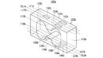
本第3実施形態に係る計量装置10b(図8参照)は、図7に示すようなロードセル100bを備えている。このロードセル100bは言わば、図1に示した第1実施形態におけるロードセル100と、図5に示した第2実施形態におけるロードセル100aとを、互いに掛け合わせたような構成をしている。具体的には、当該ロードセル100bは、第1実施形態におけるロードセル100および第2実施形態におけるロードセル100aのそれぞれと同様のロバーバル型の起歪体110bと、この起歪体110bの4箇所の起歪部122b〜128bに適宜に貼着された互いに同一仕様の合計6個の歪みゲージ132b,134b,142b,144b,152bおよび154bと、を有している。 A weighing
より具体的には、起歪体110bの上側梁部112bに形成されている2箇所の起歪部122aおよび124bの一方122bに、1個の歪みゲージ132bが貼着されており、他方の起歪部124bに、2個の歪みゲージ142bおよび152bが貼着されている。ここで、一方の起歪部122bに貼着されている歪みゲージ132bは、上側梁部112bの延伸方向に沿う中心線CL1b上に配置されており、他方の起歪部124bに貼着されている2個の歪みゲージ142bおよび152bは、当該中心線CL1bに関して互いに対称を成すように配置されており、詳しくは当該中心線CL1bに関して互いに対称を成す2つの直線L11bおよびL12b上に配置されている。これと同様に、起歪体110bの下側梁部114bに形成されている2箇所の起歪部126aおよび128bの一方126bに、1個の歪みゲージ134bが貼着されており、他方の起歪部128bに、2個の歪みゲージ144bおよび154bが貼着されている。ここで、一方の起歪部126bに貼着されている歪みゲージ134bは、下側梁部114bの延伸方向に沿う中心線CL2b上に配置されており、他方の起歪部128bに貼着されている2個の歪みゲージ144bおよび154bは、当該中心線CL2bに関して互いに対称を成すように配置されており、詳しくは当該中心線CL2bに関して互いに対称を成す2つの直線L21bL22b上に配置されている。なお、起歪体110bの固定部116bおよび可動部118bについては、第1実施形態および第2実施形態それぞれのものと同様であるので、それらの説明は省略する。 More specifically, one
このロードセル100bを構成する合計6個の歪みゲージ132b,134b,142b,144b,152bおよび154bは、図6に示す如く接続されることで、2つのブリッジ回路22bおよび24bを形成している。具体的には、一方のブリッジ回路22bは、4個の歪みゲージ132b,134b,142bおよび144bの組合せによって形成されている。即ち、圧縮歪みを検出する2個の歪みゲージ132bおよび144bが互いに対向すると共に、伸長歪みを検出する2個の歪みゲージ134bおよび142baが互いに対向するように、当該ブリッジ回路22bが形成されている。そして、他方のブリッジ回路24bは、一方のブリッジ回路22bと共通の2個の歪みゲージ132bおよび134bと、当該一方のブリッジ回路22bと非共通の2個の歪みゲージ152bおよび154bと、の計4個の組合せによって形成されている。即ち、圧縮歪みを検出する2個の歪みゲージ132bおよび154bが互いに対向すると共に、伸長歪みを検出する2個の歪みゲージ134bおよび152bが互いに対向するように、当該ブリッジ回路24bが形成されている。 A total of six
これら各ブリッジ回路22bおよび24bは、第2実施形態における各ブリッジ回路22aおよび24aと同様に、互いに共通の図示しない電源回路から例えば直流の電源電圧Viの供給を受ける。その上で、これら各ブリッジ回路22bおよび24bは、起歪体110bに印加されている荷重の大きさに比例した電圧の荷重信号Vo1およびVo2を出力し、厳密には当該荷重の大きさの変化量に比例した電圧変化量を示す荷重信号Vo1およびVo2を出力する。そして、各荷重信号Vo1およびVo2は、互いに別個の増幅回路32bおよび34bに入力される。これ以降は、第1実施形態または第2実施形態と同様である。 Each of the
このような構成の本第3実施形態によっても、第1実施形態および第2実施形態と同様、SN比の高い加算後信号WA(またはWA’)を得ることができ、ひいては安定した重量測定値WNを得ることができ、つまり静的計量精度の向上を図ることができる。そして、特に動的秤において、より定格容量の大きいロードセル100aを採用することで、高い静的計量精度を維持しつつ、より高い動的計量精度を得ることができ、つまりはより高速計量に適した性能を呈することができる。また例えば、第2実施形態と同様、ロードセル100bについての異常検出機能を付加することができる。この場合、各ブリッジ回路22bおよび24bの不平衡成分や正常な範囲内での温度ドリフト,零点変動等があるとしても、これらの影響を受けない精確な当該異常検出を実現することができる。 Also according to the third embodiment having such a configuration, as in the first embodiment and the second embodiment, it is possible to obtain the post-addition signal WA (or WA ′) having a high S / N ratio, and thus a stable weight measurement value. WN can be obtained, that is, the accuracy of static weighing can be improved. In particular, in the dynamic balance, by adopting the
次に、本発明の第4実施形態について、図9〜図11を参照して説明する。 Next, a fourth embodiment of the present invention will be described with reference to FIGS.
本第4実施形態に係る計量装置10cは、図9に示すようなトラックスケールである。このトラックスケールとしての計量装置10cは、概略矩形平板状の計量台12cを備えている。そして、この計量台12cをその下方から支持するように、当該計量台12cの四隅のそれぞれにデジタル式のロードセル100cが配置されている。それぞれのロードセル100cには、個別の識別番号m(m=1〜4)が付されている。そして、当該それぞれのロードセル100cは、後述する如くデジタル荷重信号WD[m]を出力する。このデジタル荷重信号WD[m]は、演算手段としての重量指示計400cに入力される。 The weighing
それぞれのロードセル100cは、図10に示すような角柱型の起歪体110cを有している。そして、この起歪体150の4つの側面に、圧縮歪み検出用の4個の歪みゲージ122c〜128cと、伸長歪み検出用の4個の歪みゲージ132c〜138cと、が貼着されている。なお、圧縮歪み検出用の各歪みゲージ122c〜128cは、互いに同一仕様のものである。また、伸長歪み検出用の各歪みゲージ132c〜138cも、互いに同一仕様のものであり、例えば圧縮歪み検出用の各歪みゲージ122c〜128cと同一仕様のものである。起歪体110cは、その中心軸Ax(延伸方向)に直交する断面が概略正方向のものであるが、当該断面が円形のものであってもよく、つまり円柱型のものであってもよい。この場合は、起歪体110cの中心軸Axの円周方向に沿って等間隔(90度間隔)に圧縮歪み検出用の各歪みゲージ122c〜128cと伸長歪み検出用の各歪みゲージ132c〜138cとが配置される。また、図示は省略するが、起歪体110cの両端は、概略凸面状に成形されている。それぞれのロードセル100cは、この起歪体110cの両端の一方を計量台12cの下面(厳密には計量台12cの下面に設けられた適当な上側部材の接触面)に接触させると共に、当該起歪体110cの両端の他方を基礎面(厳密には基礎面に設けられた適当な下側部材の接触面)に接触させた状態で、計量台12cを支持している。 Each
このロードセル100cを構成する合計8個の歪みゲージ122c〜128cおよび132c〜138cは、図11に示す如く接続されることで、1つのブリッジ回路20cを形成している。具体的には、起歪体110cの中心軸Axを挟んで配置されている2個の圧縮歪み検出用の歪みゲージ122cおよび126cから成る直列回路と、他の2個の圧縮歪み検出用の歪みゲージ124cおよび128cから成る直列回路と、が互いに対向すると共に、起歪体110cの中心軸Axを挟んで配置されている個の伸長歪み検出用の歪みゲージ132cおよび136cから成る直列回路と、他の2個の伸長歪み検出用の歪みゲージ134cおよび138cから成る直列回路と、が互いに対向するように、当該ブリッジ回路20cが形成されている。 A total of eight
ブリッジ回路20cは、図示しない電源回路から例えば直流の電源電圧Viの供給を受け、その上で、起歪体110cに印加されている荷重の大きさに応じた電圧の荷重信号Vo、厳密には当該荷重の大きさの変化量に応じた電圧変化量を示す荷重信号Vo、を出力する。この荷重信号Voは、複数の、例えば2つの、増幅回路32cおよび34cに入力される。 The
各増幅回路32cおよび34cは、互いに同一仕様のものであり、例えば図3に示したのと同様の計装アンプである。そして、これら各増幅回路32cおよび34cによる増幅後の各荷重信号Wa1およびWa2は、加算回路40cに入力される。この加算回路40cは、例えば図4に示したのと同様のアナログ加算回路である。 The
加算回路40cによる加算後の荷重信号WA’(=Wa1+Wa2)は、A/D変換回路50cに入力され、ここでアナログ信号からデジタル信号WDに変換される。そして、この変換後のデジタル荷重信号WDは、伝送回路60cに入力される。伝送回路60cは、このデジタル荷重信号WDに上述した識別番号mを付した上で、この識別番号mが付されたデジタル荷重信号WD[m]を出力する。このデジタル荷重信号WD[m]は、上述の如く重量指示計400cに入力される。 The load signal WA ′ (= Wa1 + Wa2) after addition by the
なお、各増幅回路32cおよび34c,加算回路40c,A/D変換回路50c,伝送回路60cは、プリント配線板200cに搭載されている。そして、ブリッジ回路20cの電源電圧Viの供給源である上述の電源回路もまた、当該プリント配線板200cに搭載されている。このプリント配線板200cは、起歪体110cの近傍に設けられており、言わばロードセル100cに内蔵されている。 The
重量指示計400cは、それぞれのロードセル100cから入力されるデジタル荷重信号WD[m]に対して、上述したのと同様のフィルタリング処理や初期成分排除処理,スパン調整処理,零点調整処理等の適宜の処理を施す。そして、これらの処理後の各ロードセル100c,100c…についての各信号を合算することで、図示しない被計量物としてのトラックの重量を求め、つまり当該トラックの重量測定値WNを求める。 The
このような構成の本第4実施形態によっても、第1〜第3の各実施形態と同様、SN比の高い加算後信号WA’を得ることができ、ひいては安定した重量測定値WNを得ることができ、つまり静的計量精度の向上を図ることができる。そして、特に動的秤において、より定格容量の大きいロードセル100aを採用することで、高い静的計量精度を維持しつつ、より高い動的計量精度を得ることができ、つまりはより高速計量に適した性能を呈することができる。 Also in the fourth embodiment having such a configuration, as in the first to third embodiments, it is possible to obtain the added signal WA ′ having a high SN ratio, and thus to obtain a stable weight measurement value WN. In other words, the static weighing accuracy can be improved. In particular, in the dynamic balance, by adopting the
なお、本第4実施形態においても、歪みゲージを追加して、ブリッジ回路の数を増やしてもよい。また、上述の第3実施形態と同様に、各ブリッジ回路がそれぞれの一部に互いに共通の歪みゲージを用いる構成としてもよい。 In the fourth embodiment, strain gauges may be added to increase the number of bridge circuits. Further, similarly to the third embodiment described above, each bridge circuit may use a common strain gauge as a part of each bridge circuit.
次に、本発明の第5実施形態について、図12を参照して説明する。 Next, a fifth embodiment of the present invention will be described with reference to FIG.
本第5実施形態に係る計量装置10dもまた、トラックスケールであり、4つのロードセル100d,100d,…を有している。ただし、本第5実施形態におけるそれぞれのロードセル100dは、上述の第4実施形態におけるものとは異なり、アナログ式のものである。即ち、図示は省略するが、本第5実施形態におけるそれぞれのロードセル100dは、図10に示したのと同様のものであり、直流の電源電圧Viの供給を受けた上で、起歪体に印加されている荷重の大きさに応じた電圧の荷重信号Voを出力し、厳密には当該荷重の大きさの変化量に応じた電圧変化量を示す荷重信号Voを出力する。なおここでは、それぞれのロードセル100dから出力される荷重信号Voについて、上述したのと同様の識別番号m(m=1〜4)を付して表す。 The weighing
例えば、識別番号mがm=1のロードセル100d(LC[1])から出力された荷重信号Vo[1]は、互いに別個の増幅回路221dおよび241dに入力される。これと同様に、識別番号mがm=2のロードセル100d(LC[2])から出力された荷重信号Vo[2]もまた、互いに別個の増幅回路222dおよび242dに入力される。そして、識別番号mがm=3のロードセル100d(LC[3])から出力された荷重信号Vo[3]は、互いに別個の増幅回路223dおよび243dに入力される。さらに、識別番号mがm=4のロードセル100d(LC[4])から出力された荷重信号Vo[4]は、互いに別個の増幅回路224dおよび244dに入力される。なお、各増幅回路221d,241d,222d,242d,223d,243d,224dおよび244dは、互いに同一仕様のものであり、例えば図3に示したのと同様の計装アンプである。 For example, the load signal Vo [1] output from the
各増幅回路221d,241d,222d,242d,223d,243d,224dおよび244dによる増幅後の各荷重信号Wa1[1],Wa2[1],Wa1[2],Wa2[2],Wa1[3],Wa2[3],Wa1[4]およびWa2[4]は、演算増幅器302dを用いたアナログ加算回路30dに入力される。具体的には、当該各増幅回路221d,241d,222d,242d,223d,243d,224dおよび244dによる各増幅後荷重信号Wa1[1],Wa2[1],Wa1[2],Wa2[2],Wa1[3],Wa2[3],Wa1[4]およびWa2[4]は、互いに別個の抵抗器304d〜318dを介して、演算増幅器302dの反転入力端子に入力される。この演算増幅器302dの非反転入力端子は、接地電位に接続されている。さらに、この演算増幅器302dの反転入力端子は、帰還抵抗320dを介して、当該演算増幅器302dの出力端子に接続されている。この演算増幅器302dの出力端子がアナログ加算回路30dの出力端子であり、この出力端子から当該アナログ加算回路30dによる加算後の加算後信号WA’(=Wa1[1]+Wa2[1]+Wa1[2]+Wa2[2]+Wa1[3]+Wa2[3]+Wa1[4]+Wa2[4])が出力される。そして、この加算後荷重信号WA’は、重量指示計400dに入力される。 Each of the load signals Wa1 [1], Wa2 [1], Wa1 [2], Wa2 [2], Wa1 [3], amplified by the
なお、各増幅回路221d,241d,222d,242d,223d,243d,224dおよび244dと加算回路30dとは、プリント配線板200dに搭載されている。そして、それぞれのロードセル100dの電源電圧Viの供給源である電源回路もまた、当該プリント配線板200dに搭載されている。このプリント配線板200dは、可能な限り各ロードセル100d,100d,…に近い位置に設けられており、例えばいずれかのロードセル100dに内蔵されている。 The
重量指示計400dは、上述の加算後荷重信号WA’をアナログ信号からデジタル信号に変換した後、上述したのと同様のフィルタリング処理や初期荷重排除処理,スパン調整処理,零点調整処理等の適宜の処理を施す。そして、これらの処理後の信号に基づいて、被計量物としてのトラックの重量測定値WNを求める。 The
このような構成の本第5実施形態によっても、第1〜第4の各実施形態と同様、SN比の高い加算後信号WA’を得ることができ、ひいては安定した重量測定値WNを得ることができ、つまり静的計量精度の向上を図ることができる。そして、特に動的秤において、より定格容量の大きいロードセル100aを採用することで、高い静的計量精度を維持しつつ、より高い動的計量精度を得ることができ、つまりはより高速計量に適した性能を呈することができる。 Also according to the fifth embodiment having such a configuration, as in the first to fourth embodiments, it is possible to obtain the added signal WA ′ having a high S / N ratio, and thus to obtain the stable weight measurement value WN. In other words, the static weighing accuracy can be improved. In particular, in the dynamic balance, by adopting the
次に、本発明の第6実施形態について、図13を参照して説明する。 Next, a sixth embodiment of the present invention will be described with reference to FIG.
本第6実施形態に係る計量装置10eもまた、トラックスケールであり、4つのロードセル100e,100e,…を有している。ただし、本第5実施形態におけるそれぞれのロードセル100eは、外観的には、図10に示したのと同様のものであるが、電気的には、図13に示すような2つのブリッジ回路22eおよび24eを形成している。なお、これら2つのブリッジ回路22eおよび24eを形成する各歪みゲージ122e〜128eおよび132e〜138eは、図10に示したロードセル100cにおける各歪みゲージ122c〜128cおよび132c〜138cに対応する。 The weighing device 10e according to the sixth embodiment is also a track scale and includes four
即ち、起歪体110eの中心軸Axを挟んで配置されている2個の圧縮歪み検出用の歪みゲージ122eおよび126eが互いに対向すると共に、当該起歪体110eにおけるこれら各歪みゲージ122eおよび126eと同じ面に配置されている2個の伸長歪み検出用の歪みゲージ132eおよび136eが対向するようにして、一方のブリッジ回路22eが形成されている。そして、他の2個の圧縮歪み検出用の歪みゲージ124eおよび128eが互いに対向すると共に、他の2個の伸長歪み検出用の歪みゲージ134eおよび138eが互いに対向するようにして、他方のブリッジ回路20eが形成されている。 That is, two
各ブリッジ回路22eおよび24eは、互いに共通の図示しない電源回路から例えば直流の電源電圧Viの供給を受ける。その上で、これら各ブリッジ回路22eおよび24eは、起歪体110eに印加されている荷重の大きさに応じた電圧の荷重信号Vo1およびVo2を出力し、厳密には当該荷重の大きさの変化量に応じた電圧変化量を示す荷重信号Vo1およびVo2を出力する。これら各荷重信号Vo1およびVo2は、互いに別個の増幅回路32eおよび34beに入力される。 Each of the
各増幅回路32eおよび34eは、互いに同一仕様のものであり、例えば図3に示したのと同様の計装アンプである。そして、これら各増幅回路32eおよび34eによる増幅後の各荷重信号Wa1およびWa2は、加算回路40eに入力される。この加算回路40eは、例えば図4に示したのと同様のアナログ加算回路である。 The
加算回路40eによる加算後の荷重信号WA’(=Wa1+Wa2)は、A/D変換回路50eに入力され、ここでアナログ信号からデジタル信号WDに変換される。そして、この変換後のデジタル荷重信号WDは、伝送回路60eに入力される。伝送回路60eは、このデジタル荷重信号WDに上述と同様の識別番号mを付した上で、この識別番号mが付されたデジタル荷重信号WD[m]を出力する。このデジタル荷重信号WD[m]は、図9に示した第4実施形態におけるのと同様の重量指示計に入力される。 The load signal WA ′ (= Wa1 + Wa2) after the addition by the
なお、各増幅回路32eおよび34e,加算回路40e,A/D変換回路50e,伝送回路60eは、プリント配線板200eに搭載されている。そして、ブリッジ回路20eの電源電圧Viの供給源である上述の電源回路もまた、当該プリント配線板200eに搭載されている。このプリント配線板200eは、起歪体110eの近傍に設けられており、つまりロードセル100eに内蔵されている。 The
このような構成の本第6実施形態によっても、第1〜第5の各実施形態と同様、SN比の高い加算後信号WA’を得ることができ、ひいては安定した重量測定値WNを得ることができ、つまり静的計量精度の向上を図ることができる。そして、特に動的秤において、より定格容量の大きいロードセル100aを採用することで、高い静的計量精度を維持しつつ、より高い動的計量精度を得ることができ、つまりはより高速計量に適した性能を呈することができる。 Also in the sixth embodiment having such a configuration, as in the first to fifth embodiments, it is possible to obtain the added signal WA ′ having a high S / N ratio, and thus to obtain a stable weight measurement value WN. In other words, the static weighing accuracy can be improved. In particular, in the dynamic balance, by adopting the
次に、本発明の第7実施形態について、図14を参照して説明する。 Next, a seventh embodiment of the present invention will be described with reference to FIG.
本第7実施形態に係る計量装置10dもまた、トラックスケールであり、4つのロードセル100f,100f,…を有している。ただし、本第7実施形態におけるそれぞれのロードセル100fは、アナログ式のものである。具体的には、図示は省略するが、本第7実施形態におけるそれぞれのロードセル100fは、上述の第6実施形態におけるのと同様のものであり、直流の電源電圧Viの供給を受けた上で、起歪体に印加されている荷重の大きさに応じた電圧の荷重信号Voを出力し、厳密には当該荷重の大きさの変化量に応じた電圧変化量を示す荷重信号Voを出力する。なおここでは、それぞれのロードセル100fから出力される荷重信号Voについて、上述と同様の識別番号m(m=1〜4)を付して表す。 The weighing
図14に示すように、例えば識別番号mがm=1のロードセル100f(LC[1])から出力された2つの荷重信号Vo1[1]およびVo2[2]は、互いに別個の増幅回路221fおよび241fに入力される。これと同様に、識別番号mがm=2のロードセル100f(LC[2])から出力された2つの荷重信号Vo1[2]およびVo2[2]もまた、互いに別個の増幅回路222fおよび242fに入力される。そして、識別番号mがm=3のロードセル100f(LC[3])から出力された2つの荷重信号Vo1[3]およびVo2[3]は、互いに別個の増幅回路223fおよび243fに入力される。そして、識別番号mがm=4のロードセル100f(LC[4])から出力された2つの荷重信号Vo1[4]およびVo2[4]は、互いに別個の増幅回路224fおよび242fに入力される。なお、各増幅回路221f,241f,222f,242f,223f,243f,224fおよび244fは、互いに同一仕様のものであり、例えば図3に示したのと同様の計装アンプである。 As shown in FIG. 14, for example, the two load signals Vo1 [1] and Vo2 [2] output from the
各増幅回路221f,241f,222f,242f,223f,243f,224fおよび244fによる増幅後の各荷重信号Wa1[1],Wa2[1],Wa1[2],Wa2[2],Wa1[3],Wa2[3],Wa1[4]およびWa2[4]は、演算増幅器302fを用いたアナログ加算回路30fに入力される。具体的には、当該各増幅回路221f,241f,222f,242f,223f,243f,224fおよび244fによる各増幅後荷重信号Wa1[1],Wa2[1],Wa1[2],Wa2[2],Wa1[3],Wa2[3],Wa1[4]およびWa2[4]は、互いに別個の抵抗器304f〜318fを介して、演算増幅器302fの反転入力端子に入力される。この演算増幅器302fの非反転入力端子は、接地電位に接続されている。さらに、この演算増幅器302fの反転入力端子は、帰還抵抗320fを介して、当該演算増幅器302fの出力端子に接続されている。この演算増幅器302fの出力端子がアナログ加算回路30fの出力端子であり、この出力端子から当該アナログ加算回路30fによる加算後の加算後信号WA’(=Wa1[1]+Wa2[1]+Wa1[2]+Wa2[2]+Wa1[3]+Wa2[3]+Wa1[4]+Wa2[4])が出力される。そして、この加算後荷重信号WA’は、図12に示した第5実施形態におけるのと同様の重量指示計400fに入力される。 Each load signal Wa1 [1], Wa2 [1], Wa1 [2], Wa2 [2], Wa1 [3], amplified by the
なお、各増幅回路221f,241f,222f,242f,223f,243f,224fおよび244fと加算回路30fとは、プリント配線板200fに搭載されている。そして、それぞれのロードセル100fの電源電圧Viの供給源である電源回路もまた、当該プリント配線板200fに搭載されている。このプリント配線板200fは、可能な限り各ロードセル100f,100f,…に近い位置に設けられており、例えばいずれかのロードセル100fに内蔵されている。 Each
このような構成の本第7実施形態によっても、第1〜第6の各実施形態と同様、SN比の高い加算後信号WA’を得ることができ、ひいては安定した重量測定値WNを得ることができ、つまり静的計量精度の向上を図ることができる。そして、特に動的秤において、より定格容量の大きいロードセル100aを採用することで、高い静的計量精度を維持しつつ、より高い動的計量精度を得ることができ、つまりはより高速計量に適した性能を呈することができる。 Also according to the seventh embodiment having such a configuration, as in the first to sixth embodiments, it is possible to obtain an added signal WA ′ having a high SN ratio, and thus to obtain a stable weight measurement value WN. In other words, the static weighing accuracy can be improved. In particular, in the dynamic balance, by adopting the
次に、本発明の第8実施形態について、図15および図16を参照して説明する。 Next, an eighth embodiment of the present invention will be described with reference to FIGS.
本第8実施形態に係る計量装置10g(図16参照)は、図15(a)に示すようなフォースバランス式ロードセル100gを荷重センサとして採用するものである。このフォースバランス式ロードセル100gは、図1に示した第1実施形態における起歪体110(または図5に示した第2実施形態における起歪体110aもしくは図7に示した第3実施形態における起歪体110b)と似たような形状の荷重被印加手段としてのロバーバルリンク110gを有している。このロバーバルリンク110gの各起歪部122g〜128gそれぞれの厚みは、図1に示した第1実施形態における起歪体110の各起歪部122〜128それぞれの厚みよりもかなり小さく、つまり当該各起歪部122g〜128gそれぞれのバネ定数は、第1実施形態における起歪体110の各起歪部122〜128それぞれのバネ定数よりもかなり小さい。 The weighing
このロバーバルリンク110gは、その上側梁部112gおよび下側梁部114gのそれぞれが水平方向に沿って延伸するように基部500gに固定されており、詳しくはその固定部118gが鉛直面を成す当該基部500gに固定されている。そして、このロバーバルリンク110gの可動部116gには、水平方向に沿って延伸する凸状部130gが設けられている。また、図示は省略するが、このロバーバルリンク110gの可動部116gには、適当な連結部材を介して計量台が結合されており、この計量台を介して当該可動部116gに荷重Wが印加される。 The global link 110g is fixed to the
さらに、ロバーバルリンク110gの凸状部130gには、その下部の適当な位置から鉛直方向に沿って延伸する概略棒状の荷重伝達部材140gが結合されており、この荷重伝達部材140gの先端部(図15(a)における下方側端部)には、鉛直方向に沿って細長い概略円柱形または概略四角柱形の磁石ユニット150gが結合されている。そして、この磁石ユニット150gの周囲を取り巻くように、電磁コイル160gが設けられている。 Furthermore, a substantially rod-shaped
具体的には、図15(b)に示すように、磁石ユニット150gは、2つの短棒状の永久磁石152gおよび154gを有しており、これら2つの永久磁石152gおよび154gは、適当な間隔を置いて互いのN極を対向させた状態で、つまり互いのS極を反対方向に向けた状態で、垂直方向に沿って直列を成すように、設けられている。また、これら各永久磁石152gおよび154gは、保護用の適当な筐体156g内に収容されている。この磁石ユニット150gは、当該図15(b)に破線の矢印158g,158g,…で示すように、電磁コイル160gを横切る方向の磁界(磁力線)を発生する。電磁コイル160gは、磁石ユニット150gと共同して、ロバーバルリンク110gに印加される荷重Wと平衡する電磁力を生成するものであり、この電磁力を生成するために、電流制御手段としてのPID(Proportional-Integral-Derivative)制御回路170gから直流の励磁電流Iの供給を受ける。 Specifically, as shown in FIG. 15 (b), the
PID制御回路170gには、例えば光学式の位置センサ180gが接続されており、この位置センサ180gは、上述の凸状部130gの先端部(図15(a)における右側端部)の位置を検出する。そして、PID制御回路170gは、位置センサ180gから供給される位置検出信号Spに基づいて、荷重Wと平衡する電磁力が生成されるように、つまり当該位置センサ180gによって検出される凸状部130gの先端部の位置が不動となるように、電磁コイル160gに供給される励磁電流Iを生成する。この励磁電流Iは、電磁コイル160gを通って、さらに参照抵抗器190gを介して、設置電位に流れる。 For example, an
励磁電流Iの大きさは、荷重Wの大きさと比例(I∝W)する。従って、この励磁電流Iの大きさから、荷重Wの大きさを求めることができる。言い換えれば、励磁電流Iが参照抵抗器190gを流れることによって、参照抵抗器190gの両端にその抵抗値Rと励磁電流Iの大きさとに応じた電圧V(=R・I)が発生する。そして、この電圧Vの大きさから、荷重Wの大きさを求めることができる。 The magnitude of the excitation current I is proportional to the magnitude of the load W (I∝W). Therefore, the magnitude of the load W can be obtained from the magnitude of the exciting current I. In other words, when the exciting current I flows through the
そこで、この参照抵抗器190gの両端に発生する電圧Vは、フォースバランス式ロードセル100gの出力信号として、図16に示すように、複数の、例えば2つの、増幅回路32gおよび34gに入力される。これら各増幅回路32gおよび34gは、互いに同一仕様のものであり、例えば演算増幅器322gおよび342gを用いた高入力インピーダンスの非反転増幅回路である。 Therefore, the voltage V generated across the
即ち、一方の増幅回路32gを構成する演算増幅器322gの非反転入力端子に、フォースバランス式ロードセル100gの出力信号Vが入力される。そして、この演算増幅器322gの反転入力端子は、接地抵抗器324gを介して、接地電位に接続されている。さらに、この演算増幅器322gの入力端子は、帰還抵抗器322gを介して、当該演算増幅器322gの出力端子に接続されている。そして、この演算増幅器322gの出力端子が、増幅回路32g全体としての出力端子とされる。 That is, the output signal V of the force balance
他方の増幅回路34gについても同様に、この他方の増幅回路34gを構成する演算増幅器342gの非反転入力端子に、フォースバランス式ロードセル100gの出力信号Vが入力される。そして、この演算増幅器342gの反転入力端子は、接地抵抗器344gを介して、接地電位に接続されている。さらに、この演算増幅器342gの入力端子は、帰還抵抗器342gを介して、当該演算増幅器342gの出力端子に接続されている。そして、この演算増幅器342gの出力端子が、増幅回路34g全体としての出力端子とされる。 Similarly, with respect to the
そして、各増幅回路32gおよび34gによる増幅後の各増幅後信号Wa1およびWa2は、アナログ加算回路40gに入力される。即ち、このアナログ加算回路40gは、演算増幅器402gを有している。そして、各増幅回路32gおよび34gによる増幅後の各増幅後信号Wa1およびWa2は、互いに別個の抵抗器404fおよび406gを介して、この演算増幅器402gの反転入力端子に入力される。なお、この演算増幅器402gの非反転入力端子は、接地電位に接続されている。さらに、この演算増幅器402gの反転入力端子は、帰還抵抗器408gを介して、当該演算増幅器402gの出力端子に接続されている。この演算増幅器402gの出力端子が、アナログ加算回路40g全体としての出力端子であり、この出力端子から、当該アナログ加算回路40gによる加算後の加算後信号WA’(=Wa1+Wa2)が出力される。そして、図示は省略するが、この加算後信号WA’は、A/D変換回路によってアナログ信号からデジタル信号に変換され、この変換後のデジタル加算後信号に基づいて、被計量物の重量が求められ、つまり重量測定値WNが求められる。 The amplified signals Wa1 and Wa2 after being amplified by the
このような構成の本第8実施形態によっても、SN比の高い加算後信号WA’を得ることができ、ひいては安定した重量測定値WNを得ることができ、つまり静的計量精度の向上を図ることができる。本第8実施形態の如く荷重センサとしてフォースバランス式ロードセル100gを採用する計量装置10gは、とりわけ、高い静的計量精度が要求される電子天秤に適用されることが多いので、このような用途において、当該静的計量精度の向上を図ることのできる本第8実施形態は、極めて有益である。また、本第8実施形態に係る計量装置10gは、動的秤にも適用することができる。本第8実施形態おいては、PID制御回路170gの利得が、フォースバランス式ロードセル100g全体としてのバネ定数を決定し、つまり当該フォースバランス式ロードセル100g全体としての定格容量を決定づける。従って、動的秤に適用される場合には、このフォースバランス式ロードセル100g全体としての定格容量を大きくすることで、高い静的計量精度を維持しつつ、より高い動的計量精度を得ることができ、つまりはより高速計量に適した性能を呈することができる。 Also according to the eighth embodiment having such a configuration, it is possible to obtain the post-addition signal WA ′ having a high S / N ratio and to obtain a stable weight measurement value WN, that is, to improve the static weighing accuracy. be able to. The weighing
10 計量装置
22,24 ホイートストンブリッジ回路
32,34 増幅回路
90 加算回路
92 乗算回路
100 ロードセル
110 起歪体
132〜134 歪みゲージDESCRIPTION OF
Claims (3)
Translated fromJapaneseそれぞれ演算増幅器を用いるものであり上記荷重信号を互いに並行して増幅する複数の増幅手段と、
上記複数の増幅手段による増幅後の複数の増幅後信号を互いに加算する加算手段と、
上記加算手段による加算後の加算後信号に基づいて上記荷重に含まれている被計量物の重量を求める重量演算手段と、
を具備し、
上記荷重信号は上記荷重の印加状況に応じた過渡応答振動を含む、
計量装置。A load sensor that applies a load and outputs a load signal in a mode corresponding to the magnitude of the load;
A plurality of amplification means each using an operational amplifier and amplifying the load signal in parallel with each other;
Adding means for adding together a plurality of amplified signals after amplification by the plurality of amplifying means;
Weight calculating means for obtaining the weight of the object to be weighed included in the load based on the signal after addition by the adding means;
Comprising
The load signal includes a transient response vibration according to an application state of the load.
Weighing device.
請求項1に記載の計量装置。The load sensor is a strain gauge type load cell.
The weighing device according to claim 1.
請求項1に記載の計量装置。The load sensor is a force balance type load cell.
The weighing device according to claim 1.
Priority Applications (1)
| Application Number | Priority Date | Filing Date | Title |
|---|---|---|---|
| JP2015028561AJP2016151461A (en) | 2015-02-17 | 2015-02-17 | Weighting device |
Applications Claiming Priority (1)
| Application Number | Priority Date | Filing Date | Title |
|---|---|---|---|
| JP2015028561AJP2016151461A (en) | 2015-02-17 | 2015-02-17 | Weighting device |
Publications (1)
| Publication Number | Publication Date |
|---|---|
| JP2016151461Atrue JP2016151461A (en) | 2016-08-22 |
Family
ID=56696452
Family Applications (1)
| Application Number | Title | Priority Date | Filing Date |
|---|---|---|---|
| JP2015028561APendingJP2016151461A (en) | 2015-02-17 | 2015-02-17 | Weighting device |
Country Status (1)
| Country | Link |
|---|---|
| JP (1) | JP2016151461A (en) |
Cited By (1)
| Publication number | Priority date | Publication date | Assignee | Title |
|---|---|---|---|---|
| JP2019039870A (en)* | 2017-08-28 | 2019-03-14 | ファナック株式会社 | Detector |
Citations (7)
| Publication number | Priority date | Publication date | Assignee | Title |
|---|---|---|---|---|
| US3616690A (en)* | 1970-06-25 | 1971-11-02 | Searle Medidata Inc | Weight measuring apparatus |
| JPS49118455A (en)* | 1973-03-12 | 1974-11-12 | ||
| JPH0377024A (en)* | 1989-08-21 | 1991-04-02 | Anritsu Corp | Electromagnetic compensation balance |
| JPH07209066A (en)* | 1993-12-02 | 1995-08-11 | Ishida Co Ltd | Multi-point cell type weighing equipment |
| JP2006184192A (en)* | 2004-12-28 | 2006-07-13 | Shimadzu Corp | Electronic balance |
| JP2012173165A (en)* | 2011-02-22 | 2012-09-10 | Anritsu Sanki System Co Ltd | Measuring device |
| JP2013253834A (en)* | 2012-06-06 | 2013-12-19 | Yamato Scale Co Ltd | Non-automatic scale |
- 2015
- 2015-02-17JPJP2015028561Apatent/JP2016151461A/enactivePending
Patent Citations (7)
| Publication number | Priority date | Publication date | Assignee | Title |
|---|---|---|---|---|
| US3616690A (en)* | 1970-06-25 | 1971-11-02 | Searle Medidata Inc | Weight measuring apparatus |
| JPS49118455A (en)* | 1973-03-12 | 1974-11-12 | ||
| JPH0377024A (en)* | 1989-08-21 | 1991-04-02 | Anritsu Corp | Electromagnetic compensation balance |
| JPH07209066A (en)* | 1993-12-02 | 1995-08-11 | Ishida Co Ltd | Multi-point cell type weighing equipment |
| JP2006184192A (en)* | 2004-12-28 | 2006-07-13 | Shimadzu Corp | Electronic balance |
| JP2012173165A (en)* | 2011-02-22 | 2012-09-10 | Anritsu Sanki System Co Ltd | Measuring device |
| JP2013253834A (en)* | 2012-06-06 | 2013-12-19 | Yamato Scale Co Ltd | Non-automatic scale |
Cited By (1)
| Publication number | Priority date | Publication date | Assignee | Title |
|---|---|---|---|---|
| JP2019039870A (en)* | 2017-08-28 | 2019-03-14 | ファナック株式会社 | Detector |
Similar Documents
| Publication | Publication Date | Title |
|---|---|---|
| USRE36411E (en) | Weighing apparatus with means for correcting effects of vibrations | |
| US2597751A (en) | Bending beam load weighing device | |
| WO2008029648A1 (en) | Load cell unit, weight checker, electronic weighting instrument, and weighting instrument | |
| JP2007316071A (en) | Method for processing output signal of measurement transducer, and power-measuring device | |
| JPH06174536A (en) | Measuring apparatus | |
| CN110546471B (en) | Temperature measuring device using strain gauge | |
| US9052247B2 (en) | Device and method for evaluating signals of load cells with strain gauges | |
| JP5848880B2 (en) | Weighing device | |
| WO2020103535A1 (en) | Weight scale capable of measuring values of weights at four corners, measurement apparatus and measurement method | |
| JP2016151461A (en) | Weighting device | |
| US4475409A (en) | Transducer for dynamometer | |
| JPH0769232B2 (en) | Method and apparatus for temperature compensation of load cell | |
| US5663531A (en) | Electronic weighing apparatus utilizing surface acoustic waves | |
| US3617878A (en) | Ac to de high-accuracy low-level voltage measuring system | |
| Gaikwad et al. | Design and development of novel weighing scale system | |
| JP3465946B2 (en) | Load cell temperature compensation method and apparatus | |
| JP2016151462A (en) | Load cell | |
| JP2014109438A (en) | Strain body, load cell and weighing apparatus | |
| KR102492929B1 (en) | Weighing apparatus | |
| US3434343A (en) | Low frequency damping circuit for strain gage transducers | |
| US8082804B2 (en) | Load measuring transducer using induced voltage for reducing measuring errors and load measuring system using the same | |
| KR910001147B1 (en) | Weighing device | |
| JP3469367B2 (en) | Multi-point cell type weighing device | |
| JP2006138714A (en) | Weighing apparatus with built-in calibration device | |
| SU697818A1 (en) | Device for measuring the trim of float-type instruments at balancing |
Legal Events
| Date | Code | Title | Description |
|---|---|---|---|
| A621 | Written request for application examination | Free format text:JAPANESE INTERMEDIATE CODE: A621 Effective date:20171211 | |
| A977 | Report on retrieval | Free format text:JAPANESE INTERMEDIATE CODE: A971007 Effective date:20180907 | |
| A131 | Notification of reasons for refusal | Free format text:JAPANESE INTERMEDIATE CODE: A131 Effective date:20180918 | |
| A02 | Decision of refusal | Free format text:JAPANESE INTERMEDIATE CODE: A02 Effective date:20190312 |