JP2016150189A - Sole system for artificial leg - Google Patents
Sole system for artificial legDownload PDFInfo
- Publication number
- JP2016150189A JP2016150189AJP2015030356AJP2015030356AJP2016150189AJP 2016150189 AJP2016150189 AJP 2016150189AJP 2015030356 AJP2015030356 AJP 2015030356AJP 2015030356 AJP2015030356 AJP 2015030356AJP 2016150189 AJP2016150189 AJP 2016150189A
- Authority
- JP
- Japan
- Prior art keywords
- sole
- spike
- rubber
- prosthetic
- leg
- Prior art date
- Legal status (The legal status is an assumption and is not a legal conclusion. Google has not performed a legal analysis and makes no representation as to the accuracy of the status listed.)
- Granted
Links
Images


Classifications
- A—HUMAN NECESSITIES
- A61—MEDICAL OR VETERINARY SCIENCE; HYGIENE
- A61F—FILTERS IMPLANTABLE INTO BLOOD VESSELS; PROSTHESES; DEVICES PROVIDING PATENCY TO, OR PREVENTING COLLAPSING OF, TUBULAR STRUCTURES OF THE BODY, e.g. STENTS; ORTHOPAEDIC, NURSING OR CONTRACEPTIVE DEVICES; FOMENTATION; TREATMENT OR PROTECTION OF EYES OR EARS; BANDAGES, DRESSINGS OR ABSORBENT PADS; FIRST-AID KITS
- A61F2/00—Filters implantable into blood vessels; Prostheses, i.e. artificial substitutes or replacements for parts of the body; Appliances for connecting them with the body; Devices providing patency to, or preventing collapsing of, tubular structures of the body, e.g. stents
- A61F2/50—Prostheses not implantable in the body
- A61F2/60—Artificial legs or feet or parts thereof
Landscapes
- Health & Medical Sciences (AREA)
- Transplantation (AREA)
- Vascular Medicine (AREA)
- Life Sciences & Earth Sciences (AREA)
- Oral & Maxillofacial Surgery (AREA)
- Engineering & Computer Science (AREA)
- Biomedical Technology (AREA)
- Heart & Thoracic Surgery (AREA)
- Orthopedic Medicine & Surgery (AREA)
- Cardiology (AREA)
- Animal Behavior & Ethology (AREA)
- General Health & Medical Sciences (AREA)
- Public Health (AREA)
- Veterinary Medicine (AREA)
- Prostheses (AREA)
- Footwear And Its Accessory, Manufacturing Method And Apparatuses (AREA)
Abstract
Translated fromJapaneseDescription
Translated fromJapanese本発明は、義足用ソールシステムに関し、とくに、板ばね状の競技用義足の足部に取り付けられるソールシステムに関する。 The present invention relates to a sole system for a prosthetic leg, and more particularly to a sole system attached to a foot part of a leaf prosthetic prosthetic leg for competition.
競技用義足として、たとえば特開2011−182881号公報には、下方に延びる下腿部と下腿部の下端から前方に湾曲しつつ延びる足部とからなる板ばね状の競技用義足において、足部の下面に滑り止め用のゴムシートが取り付けられたものが記載されている(当該公報の段落[0020]および[0028]ならびに図1参照)。 As a prosthetic leg for competition, for example, Japanese Patent Application Laid-Open No. 2011-182881 discloses a leaf-spring-like prosthetic leg that is composed of a leg part extending downward and a leg part that curves forward from the lower end of the leg part. In which a non-slip rubber sheet is attached to the lower surface of the part (see paragraphs [0020] and [0028] of FIG. 1 and FIG. 1).
上記公報に記載のものは、競技用義足の足部の下面にゴムシートが装着されているため、ジョギングやランニング、屋内競技などに適している。その一方、陸上のトラック競技等においては、義足の足部の下面にスパイクを固着したものが用いられている。 Since the rubber sheet is attached to the lower surface of the foot portion of the prosthetic leg for competition, the one described in the above publication is suitable for jogging, running, indoor competition, and the like. On the other hand, in track and field events and the like, a spike is fixed to the lower surface of the leg portion of the artificial leg.
一般に、競技用義足は非常に高価なものであるため、競技種目に応じてゴムシートが装着されたものとスパイクが固着されたものの双方を用意することは、競技者の経済的負担が大きい。また、競技場のトラック以外の場所ではスパイクをカバーする必要があるが、これまで義足のスパイクを簡単にかつ確実にカバーできるようなものはなかった。 In general, since a prosthetic leg for competition is very expensive, it is very economical for the athlete to prepare both a rubber seat mounted and a spike fixed according to the competition event. In addition, it is necessary to cover the spikes at places other than the track of the stadium, but until now there has been nothing that can easily and reliably cover the spikes of the artificial leg.
本発明は、このような従来の実情に鑑みてなされたもので、本発明が解決しようとする課題は、着用者(とくに競技者)の負担を軽減でき、スパイクを簡単かつ確実にカバーできる義足用ソールシステムを提供することにある。 The present invention has been made in view of such conventional circumstances, and the problem to be solved by the present invention is to reduce the burden on the wearer (especially the athlete) and to easily and reliably cover the spike. A sole system is provided.
本発明に係る義足用ソールシステムは、義足の下面に取り付けられるスパイクソールと、スパイクソールの下方に配置され、義足に取外し可能に設けられるラバーソールとを備えている(請求項1参照)。 A prosthetic leg sole system according to the present invention includes a spike sole attached to the lower surface of the prosthetic leg, and a rubber sole that is disposed below the spike sole and is detachable from the prosthetic leg (see claim 1).
本発明においては、義足用ソールシステムをスパイクソールとして用いる際には、義足からラバーソールを取り外した状態で使用する。一方、義足用ソールシステムをラバーソールとして用いる際には、義足に取り付けられたスパイクソールの下方から義足にラバーソールを取り付けた状態で使用する。 In the present invention, when the prosthetic leg sole system is used as the spike sole, the rubber sole is removed from the artificial leg. On the other hand, when the prosthetic leg sole system is used as a rubber sole, it is used in a state where the rubber sole is attached to the artificial leg from below the spike sole attached to the artificial leg.
本発明によれば、義足として、ラバーソールが装着されたものおよびスパイクソールが固着されたものの双方を用意する必要がなくなるので、着用者(競技者)の経済的負担を軽減できる。また、競技場のトラック以外の場所でスパイクをカバーする必要がある際には、スパイクソールの下方からラバーソールを取り付けるだけでよいので、スパイクを簡単かつ確実にカバーできるようになる。 According to the present invention, it is not necessary to prepare both a rubber sole fitted with a rubber sole and a spike sole attached as a prosthetic leg, so that the economic burden on the wearer (competitor) can be reduced. Further, when it is necessary to cover the spike at a place other than the track of the stadium, it is only necessary to attach the rubber sole from below the spike sole, so that the spike can be covered easily and reliably.
本発明では、ラバーソールの上面が、スパイクソールのスパイク(またはスパイク取付部)を収容し得る凹部を有している(請求項2参照)。この場合、スパイクソールの下方からラバーソールを義足に取り付けた際には、スパイクソールのスパイク(またはスパイク取付部)がラバーソール上面の凹部に収容されるので、ラバーソールによってスパイクソールのスパイク(またはスパイク取付部)を確実にカバーできるだけでなく、ラバーソール装着時の運動の際に、スパイクソールのスパイク先端がラバーソールを傷付けるのを確実に防止できる。 In the present invention, the upper surface of the rubber sole has a recess that can accommodate the spike (or spike mounting portion) of the spike sole (see claim 2). In this case, when the rubber sole is attached to the artificial leg from the lower side of the spike sole, the spike (or spike attachment portion) of the spike sole is accommodated in the recess on the upper surface of the rubber sole. ) Can be reliably covered, and the spike tip of the spike sole can be reliably prevented from damaging the rubber sole during exercise when the rubber sole is mounted.
本発明では、ラバーソールの凹部においてスパイク(またはスパイク取付部)と対向する底壁側領域に硬質領域が設けられている(請求項3参照)。硬質領域がスパイクと対向する底壁側領域に設けられている場合には、ラバーソール装着時の運動の際に、仮にスパイクソールのスパイク先端がラバーソールの凹部の底部に当接した場合でも、スパイク先端が凹部の底部を突き抜けるのを防止できる。また、硬質領域がスパイク取付部と対向する底壁側領域に設けられている場合には、ラバーソール装着時の運動の際に、スパイク取付部が硬質領域に当接することでスパイク取付部が下方に沈み込むのを防止でき、これにより、スパイク先端が凹部の底部を突き抜けるのを防止できる。 In the present invention, a hard region is provided in the bottom wall side region facing the spike (or spike mounting portion) in the recess of the rubber sole (see claim 3). If the hard region is provided in the bottom wall side region facing the spike, even if the spike tip of the spike sole comes into contact with the bottom of the recess of the rubber sole during exercise when the rubber sole is mounted, the spike tip Can be prevented from penetrating through the bottom of the recess. In addition, when the hard region is provided in the bottom wall side region opposite to the spike mounting portion, the spike mounting portion is brought down by the spike mounting portion abutting against the hard region during the movement when the rubber sole is mounted. Sinking can be prevented, thereby preventing the spike tip from penetrating the bottom of the recess.
本発明によれば、ラバーソールの上面には、ラバーソールをスパイクソールに取り付ける際にスパイクの先端を凹部まで案内するガイド溝が形成されている(請求項4参照)。この場合には、ラバーソールをスパイクソールに取り付ける際に、スパイクソールのスパイク先端がラバーソールのガイド溝によって案内されることで、スパイクソールのスパイクをラバーソールの凹部にスムーズに収容することができ、これにより、スパイクソールに対するラバーソールの取付けをスムーズに行えるようになる。 According to the present invention, a guide groove is formed on the upper surface of the rubber sole to guide the tip of the spike to the recess when the rubber sole is attached to the spike sole (see claim 4). In this case, when attaching the rubber sole to the spike sole, the spike tip of the spike sole is guided by the guide groove of the rubber sole, so that the spike of the spike sole can be smoothly accommodated in the recess of the rubber sole. The rubber sole can be smoothly attached to the spike sole.
本発明では、ラバーソールが、義足に締結するための締結具を有している(請求項5参照)。この場合、スパイクソールの下方からラバーソールを義足に取り付ける際には、ラバーソールの締結具の締結により、ラバーソールを義足に確実に取り付けることができ、また、ラバーソールを義足から取り外す際には、ラバーソールの締結具を緩める(または開放する)ことにより、ラバーソールを義足から簡単に取り外すことができる。 In the present invention, the rubber sole has a fastener for fastening to the artificial leg (see claim 5). In this case, when attaching the rubber sole to the prosthetic leg from below the spike sole, the rubber sole can be securely attached to the artificial leg by fastening the rubber sole fastener, and when the rubber sole is removed from the artificial leg, the rubber sole is fastened. By loosening (or opening) the tool, the rubber sole can be easily removed from the prosthesis.
本発明では、ラバーソールが、スパイクソールに当接するミッドソールと、その下方に配置され、接地面を有するアウトソールとから構成されている(請求項6参照)。この場合には、ラバーソールを上下2層構造にしたことにより、各層の材質や硬度、発泡倍率等を異ならせることで、各層の材料特性を簡単に変えることができる。たとえば、アウトソールをミッドソールよりも高硬度素材から構成した場合には、接地面の耐摩耗性を向上できるばかりでなく、スパイクソールのスパイク先端がアウトソール接地面側に突き抜けるのを防止できるようになる。 In the present invention, the rubber sole includes a midsole that abuts against the spike sole and an outsole that is disposed below the midsole and has a ground contact surface (see claim 6). In this case, since the rubber sole has a two-layer structure, the material characteristics of each layer, the hardness, the foaming ratio, and the like can be varied to easily change the material characteristics of each layer. For example, when the outsole is made of a material harder than the midsole, not only can the wear resistance of the ground contact surface be improved, but also the spike tip of the spike sole can be prevented from penetrating to the outsole ground contact surface side. become.
本発明では、ラバーソールを義足に締結するための締結具の一端がミッドソールおよびアウトソール間に挟持されている(請求項7参照)。この場合には、ラバーソールをミッドソールおよびアウトソールの上下2層構造にして、締結具の一端をミッドソールおよびアウトソール間で挟持させることで、締結具のラバーソールへの固着が容易に行えるようになる。 In the present invention, one end of a fastener for fastening the rubber sole to the prosthesis is sandwiched between the midsole and the outsole (see claim 7). In this case, the rubber sole has a two-layer structure including a midsole and an outsole, and one end of the fastener is sandwiched between the midsole and the outsole so that the fastener can be easily fixed to the rubber sole. Become.
本発明では、スパイクソールが、義足の下面に装着されるスパイクソール本体部と、スパイクソール本体部の外周縁部から上方に立ち上がる立上げ部とを有している(請求項8参照)。この場合には、スパイクソールの立上げ部によって、スパイクソールを義足に取り付ける際に義足に対するスパイクソールの位置決めを行えるとともに、スパイクソールの義足への取付後にスパイクソールが義足に対して前後左右方向にずれるのを防止できる。 In the present invention, the spike sole has a spike sole main body portion mounted on the lower surface of the artificial leg and a rising portion that rises upward from the outer peripheral edge portion of the spike sole main body portion (see claim 8). In this case, the spike sole can be positioned with respect to the prosthetic leg when the spike sole is attached to the prosthetic leg by the rising part of the spike sole. It can be prevented from shifting.
本発明では、立上げ部が、スパイクソール本体部の外周縁部の複数の個所に設けられている(請求項9参照)。この場合には、立上げ部がスパイクソール本体部の外周縁部の全周にわたって連設されていないので、スパイクソールを義足下面の湾曲面に沿って配設する際に、スパイクソールを容易に湾曲させることでき、スパイクソールを義足下面に容易に密着させることができる。 In the present invention, the rising portions are provided at a plurality of locations on the outer peripheral edge of the spike sole main body (see claim 9). In this case, since the rising portion is not continuously provided over the entire circumference of the outer peripheral edge portion of the spike sole main body portion, the spike sole can be easily arranged when the spike sole is disposed along the curved surface of the lower surface of the artificial leg. The spike sole can be easily brought into close contact with the lower surface of the artificial leg.
本発明では、ラバーソールが義足に締結するための締結具を有しており、締結具が立上げ部によって係止されている(請求項10参照)。この場合には、ラバーソールを締結具で義足に締結した際に、締結部が前後方向にずれを起こすのをスパイクソールの立上げ部によって防止できる。 In the present invention, the rubber sole has a fastener for fastening to the artificial leg, and the fastener is locked by the rising portion (see claim 10). In this case, when the rubber sole is fastened to the prosthetic leg with a fastener, the fastening portion can be prevented from being displaced in the front-rear direction by the rising portion of the spike sole.
本発明では、当該ソールシステムが、湾曲した板ばね状の競技用義足の足部に取り付けられるようになっている(請求項11参照)。 In the present invention, the sole system is attached to a foot portion of a curved leaf spring-like competition artificial leg (see claim 11).
以上のように、本発明に係る義足用ソールシステムによれば、義足の下面に取り付けられるスパイクソールと、スパイクソールの下方に配置された、義足に取外し可能なラバーソールとを設けたので、義足用ソールシステムをスパイクソールとして用いる際には、義足からラバーソールを取り外した状態で使用し、義足用ソールシステムをラバーソールとして用いる際には、義足に取り付けられたスパイクソールの下方から義足にラバーソールを取り付けた状態で使用すればよく、義足として、ラバーソールが装着されたものおよびスパイクソールが固着されたものの双方を用意する必要がなくなるので、着用者(競技者)の経済的負担を軽減できる。また、競技場のトラック以外の場所でスパイクをカバーする必要がある際には、スパイクソールの下方からラバーソールを取り付けるだけでよいので、スパイクを簡単かつ確実にカバーできるようになる。 As described above, according to the prosthetic leg sole system according to the present invention, the spike sole attached to the lower surface of the prosthetic leg and the rubber sole which is disposed below the spike sole and can be detached from the prosthetic leg are provided. When using the sole system as a spike sole, the rubber sole is removed from the prosthetic leg. When using the prosthetic sole system as a rubber sole, the rubber sole is attached to the prosthetic leg from below the spike sole attached to the prosthetic leg. Since it is not necessary to prepare both a rubber sole with a rubber sole and a spike sole fixed as a prosthetic leg, the economic burden on the wearer (competitor) can be reduced. Further, when it is necessary to cover the spike at a place other than the track of the stadium, it is only necessary to attach the rubber sole from below the spike sole, so that the spike can be covered easily and reliably.
以下、本発明の実施例を添付図面に基づいて説明する。
図1ないし図8は本発明の一実施例による義足用ソールシステムを示している。ここでは、当該義足用ソールシステムが競技用義足の足部に取り付けられる場合を例にとって説明する。なお、以下の説明文中、前方(前側/前)および後方(後側/後)とは、競技用義足の足部における前後方向の位置関係を表し、上方(上側/上)および下方(下側/下)とは、競技用義足の足部における上下方向の位置関係を表すものとする。Embodiments of the present invention will be described below with reference to the accompanying drawings.
1 to 8 show a sole system for a prosthetic leg according to an embodiment of the present invention. Here, the case where the prosthetic leg sole system is attached to the foot part of the prosthetic leg for competition will be described as an example. In the following description, the front (front / front) and back (rear / rear) indicate the positional relationship in the front-rear direction of the foot of the prosthetic leg for competition, and the upper (upper / upper) and lower (lower) //)) represents the positional relationship in the vertical direction of the foot of the prosthetic leg for competition.
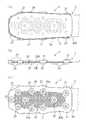
図1および図2に示すように、この義足用ソールシステム1は、一点鎖線で示す競技用義足Lの前端側の足部Sに取り付けられるようになっている。競技用義足Lは、上下方向に延びる下腿部(図示せず)と、その下端から前方に湾曲しつつ延びる足部Sとを有しており、たとえば炭素繊維強化プラスチック(CFRP)製の板ばね状の部材である。 As shown in FIGS. 1 and 2, the
ソールシステム1は、競技用義足Lの足部Sに取り付けられるスパイクソール2と、スパイクソール2の下方に配置され、足部Sに取外し可能に設けられるラバーソール3とを備えている。 The
スパイクソール2は、足部Sの下面に装着されるスパイクソール本体部20と、スパイクソール本体部20の外周縁部から上方に立ち上がる立上げ部21とを有している。スパイクソール本体部20は、足部Sの外周形状に沿う外周形状を有しており、足部Sの下面(底面)に接着等で固着されるようになっている。立上げ部21は、足部Sの外周面Saに沿うように上方に延びている。立上げ部21の高さは、足部Sの厚みに合わせて適宜設定される。また、立上げ部21は、スパイクソール本体部20の外周に沿って間隔を隔てて複数個(この例では8個)設けられている。 The spike sole 2 includes a spike sole
ラバーソール3は、足部Sに締結するための締結具4、5を有している。締結具4、5としては、ベルト、紐、ファスナー、バックル等の任意のものが適用可能である。ここでは、足部Sの前端側の締結具4としてベルト40が用いられており、足部Sの前後方向中央部および後端側の締結具5としては、BOA(登録商標)クロージャーシステムが採用されている。 The
足部Sの前端側の締結具4においては、足部Sの前端およびその後方側の左右側部にベルト係止用の係止部401、402、403がそれぞれ設けられており、各係止部401、402、403の下端はラバーソール3に固着されている。各係止部401、402、403間にはベルト40が掛け渡されており、ベルト40は面ファスナー等を介して締結されるようになっている。また、前端の係止部401の左右端はベルト40’を介してラバーソール3に連結されていてもよい。ラバーソール3に対する各係止部401、402、403の下端の取付位置は、スパイクソール2の各立上げ部21の間の間隙の位置に対応している。In the
足部Sの前後方向中央部および後端側の締結具5として採用されたBOA(登録商標)クロージャーシステムにおいては、足部Sの前後方向中央部および後端側の左右側部にそれぞれストラップ部50が設けられており、各ストラップ部50の下端はラバーソール3に固着されている。左右方向に相対する各ストラップ部50の一方には、BOA(登録商標)クロージャーシステムの操作部51が取り付けられ、他方には、操作部51から延びるワイヤー52が係止する係止部53が取り付けられている。BOA(登録商標)クロージャーシステムにおいては、操作部51の操作によりワイヤー52が弛張することで各ストラップ部50間を開放または締結するようになっている。ラバーソール3に対する各ストラップ部50の下端の取付位置は、スパイクソール2の各立上げ部21の間の間隙の位置に対応している。 In the BOA (registered trademark) closure system employed as the
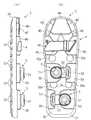
図3(a)に示すように、スパイクソール2の上面20Aには、メッシュ、フィルムまたは布帛等からなるシート22が装着されている。シート22は、たとえばスパイクソール2の射出成形時にインサート成形されている。シート22は、スパイクソール2を競技用義足Lの足部Sの下面に接着する際の接着性を向上させるために設けられており、好ましくは、上面20Aの全面領域に配設されている。 As shown in FIG. 3A, a
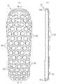
図3(c)に示すように、スパイクソール2の下面20Bには、ハニカム構造部24が設けられている。このハニカム構造部24は、六角形状の多数の貫通孔を前後左右方向に並設した構造を有しており、各貫通孔の周囲は六角形状のリブで囲繞されている。各貫通孔が上面20Aまで貫通していることで、スパイクソール2の上面20Aに装着されたシート22の上面には各貫通孔の開口縁部の輪郭の一部が現れている(同図(a)参照)。ハニカム構造部24を設けることで、スパイクソール2を軽量化できるとともに、強度を維持しつつ可撓性を向上できる。 As shown in FIG. 3C, a
図3(b)および(c)に示すように、スパイクソール2の下面20Bには、スパイク取付用の複数(この例では11個)のボス部(スパイク取付部)25が設けられている。各ボス部25には、スパイク(図示せず)を取り付けるための取付孔25aが形成されている。スパイクは、ボス部25の取付孔25aに予め固着されていてもよく、または取付孔25aに設けられた雌ねじ部(たとえば、埋設された金属製のナット)に対して雄ねじ等で着脱自在に設けられていてもよい。この例では、ボス部25にスパイクが装着されていない状態のものが示されている。 As shown in FIGS. 3B and 3C, the
ラバーソール3の締結具4、5については、図1および図2を用いて説明したとおりであるが、各締結具4、5を締結した状態の側面図および平面図を図4(a)および(b)にそれぞれ示す。図4(b)に示すように、ラバーソール3の上面には、ラバーソール3を競技用義足Lの足部Sに取り付けた際に、スパイクソール2のボス部25およびスパイクを収容し得る複数の凹部3aが形成されている(図2参照)。 The
ラバーソール3は、ミッドソール30と、ミッドソール30を下方および周方向から覆うアウトソール31とからなる2層構造を有している。ラバーソール3の締結具4、5における係止部401、402、403およびストラップ部50の各々の下端は、ミッドソール30およびアウトソール31間で挟持されている。ミッドソール30には、凹部3aを構成する貫通孔30aが形成されている。ミッドソール30の上面は、ラバーソール3を競技用義足Lの足部Sに取り付けた際にスパイクソール2の下面に当接するようになっている。アウトソール31の下面には、各々接地面を有する多数のアウトソール部32が設けられている(図5(a)および図6(a)参照)。好ましくは、ミッドソール30の各貫通孔30aと上下に対向する位置にアウトソール部32が配置されている。The
図5(b)および図6(b)に示すように、アウトソール31は、外周面31aの内側に凹部31bを有している。凹部31bは、ミッドソール30をアウトソール31内部に嵌合させるためのものである。凹部31bの底面には、各締結具4、5における係止部401、402、403、ベルト40’およびストラップ部50のそれぞれの下端を接着するための接着代33が設けられている。なお、ミッドソール30およびアウトソール31の厚みは、スパイクソール2のスパイク高さ(ボス部25からのスパイク突出長さ)に応じて適宜設定されるが、着用者の他方の足が健足である場合には、健足が着用するスパイクシューズのスパイク高さに合わせる必要がある。As shown in FIGS. 5B and 6B, the
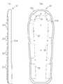
図7(a)および(b)に示すように、ミッドソール30は、複数の貫通孔30aと、前端側に配置された単一の切欠き30a’とを有している。これら切欠き30a’および貫通孔30aは、スパイクソール2の各ボス部25に対応する位置に設けられている。また、ミッドソール30の後部は、前部および中央部よりもわずかに板厚が厚くなっており、段差部30bを有している。段差部30bの段差は、スパイクソール2の板厚にほぼ等しくなっている。 As shown in FIGS. 7A and 7B, the
ラバーソール3は、締結具4、5の係止部401、402、403、ベルト40’およびストラップ部50のそれぞれの下端をアウトソール31の凹部31bの底面の各接着代33に接着し、その状態から、ミッドソール30を凹部31b内に配置して固着することにより組み立てられる。ラバーソール3の組立後は、ミッドソール30の貫通孔30aおよび切欠き30a’の下部開口は、アウトソール31の凹部31bの底面で覆われており、これら貫通孔30aおよび切欠き30a’はラバーソール3の凹部3aとして機能する。The
ここで、本実施例による義足用ソールシステム1を構成する各要素の素材について簡単に触れておく。
スパイクソール2は、たとえば、PAE(ポリアミドエラストマー)、TPU(熱可塑性ポリウレタン)、CFRP(炭素繊維強化プラスチック)、GFRP(ガラス繊維強化プラスチック)等の比較的硬質の弾性部材から構成される。ミッドソール30は、たとえば、EVA(エチレン・酢酸ビニル共重合樹脂)、ラバー、PU(ポリウレタン)等の発泡材またはソリッド材から構成される。アウトソール31としては、ミッドソール30よりも硬質の部材が好ましく、具体的には、ラバー、PU、EVA等のソリッド材または発泡材が用いられる。アウトソール31の硬度に関しては、とくにミッドソール30の貫通孔30aの底面側開口部に位置するアウトソール領域については高硬度であるのが好ましく、たとえばアスカーAスケールで70度以上に設定される。締結具を構成するベルト4、4’、各係止部401、402、403および各ストラップ部50については、人工皮革、布帛、織物等が用いられ、ワイヤー52については、金属や繊維等が用いられる。Here, the material of each element which comprises the
The spike sole 2 is composed of a relatively hard elastic member such as PAE (polyamide elastomer), TPU (thermoplastic polyurethane), CFRP (carbon fiber reinforced plastic), GFRP (glass fiber reinforced plastic), and the like. The
上述のように構成される義足用ソールシステム1を着用する際には、まず、スパイクソール2を競技用義足Lの足部Sに取り付ける(図2の上側の図参照)。この場合には、スパイクソール2の上面20Aに接着剤を塗布し、この状態から、スパイクソール2の上面20Aを競技用義足Lの足部Sの下面に当接させつつ、スパイクソール2の外周縁部の立上げ部21を足部Sの外周面Saに当接させることで、スパイクソール2を足部Sに対して適切な位置に位置決めしつつ足部Sの下面に接着する。 When wearing the prosthetic leg
このとき、スパイクソール2の上面20Aには、メッシュ、フィルムまたは布帛等からなるシート22が設けられているので、スパイクソール2を足部Sに強固に接着できる。また、このとき、足部Sの下面が湾曲している場合でも、スパイクソール2の各立上げ部21が間隔を隔てて配置されていることで、スパイクソール2のスパイクソール本体部20を容易に湾曲させることができ、これにより、スパイクソール本体部20の上面20Aを足部Sの湾曲した下面に沿って密着できる。 At this time, since the
義足用ソールシステム1をスパイクソールとして用いる際には、このようにスパイクソール2を競技用義足Lの足部Sに取り付けた状態で(つまりラバーソール3を取り付けることなく)使用する。この場合、スパイクソール2の立上げ部21が足部Sの外周面に沿って配設されていることで、スパイクソールとしての運動の際にスパイクソール2が足部Sに対して前後左右方向にずれるのを防止できる。 When the prosthetic leg
次に、義足用ソールシステム1をラバーソールとして用いる際には、競技用義足Lの足部Sに取り付けられたスパイクソール2の下方から足部Sにラバーソール3を取り付ける(図2参照)。この場合には、ラバーソール3の各締結具4、5を緩めた(または完全に開放した)状態で、スパイクソール2の下面20B(図3(b)、(c))にラバーソール3の上面を当接させるようにする。 Next, when the prosthetic leg
このとき、ラバーソール3の上面の凹部3a(すなわちミッドソール30の貫通孔30a)には、図8に示すように、スパイクソール2のスパイク取付用のボス部25が嵌合し、このとき、ボス部25にスパイク26が装着されていた場合には、凹部3a内にスパイク26も収容されることになる。また、このとき、ラバーソール3の各締結具4、5の係止部401、402、403およびストラップ部50は、スパイクソール2の隣り合う各立上げ部21間の間隙に対応する位置に配置されており(図1参照)、各締結具4、5の係止部401、402、403およびストラップ部50はそれぞれ対応する各立上げ部21に係止されている。この状態から、各締結具4、5を締結することにより、ラバーソール3が競技用義足Lの足部Sに確実に取り付けられる(図1参照)。At this time, as shown in FIG. 8, a
ラバーソールとしての運動の際には、ラバーソール3の各締結具4、5がスパイクソール2の各立上げ部21に係止されていることで(さらには、スパイクソール2のボス部25がラバーソール3の凹部3aに収容されて凹部内周面で保持されていることで)、ラバーソール3がスパイクソール2に対して前後左右方向にずれるのを防止できるとともに、スパイクソール2のスパイク26がラバーソール3の凹部3aに収容されていることで、ラバーソール3によってスパイクソール2のスパイク26を確実にカバーすることができ、スパイクソール2のスパイク26先端がラバーソール3を傷付けるのを確実に防止できる。また、ラバーソール3の凹部3aの底壁側領域には、硬質の弾性部材からなるアウトソール31が配設されているので、運動時にスパイク26先端の下方への突き抜けを硬質のアウトソール31(さらにはアウトソール部32)により防止できる。 In the exercise as the rubber sole, the
ラバーソール3を再び足部Sから取り外す際には、ラバーソール3の各締結具4、5を緩めて(または完全に開放して)、ラバーソール3をスパイクソール2から離すようにすればよい。 When the
このように本実施例によれば、競技用義足として、ラバーソールが装着されたものおよびスパイクソールが固着されたものの双方を用意する必要がなくなり、着用者(競技者)の経済的負担を軽減できる。しかも、ラバーソールとしての使用時には、スパイクソールの下方からカバーバーソールを取り付けるだけでよいので、スパイクを簡単かつ確実にカバーできるようになる。 As described above, according to this embodiment, it is not necessary to prepare both a rubber sole with a rubber sole and a spike sole fixed as a prosthetic leg for competition, and the economic burden on the wearer (competitor) can be reduced. . In addition, when used as a rubber sole, it is only necessary to attach the cover bar sole from below the spike sole, so that the spike can be covered easily and reliably.
以上、本発明に好適な実施例について説明したが、本発明の適用はこれに限定されるものではなく、本発明には種々の変形例が含まれる。以下に変形例のいくつかの例を挙げておく。なお、各変形例を示す図面において、前記実施例と同一符号は同一または相当部分を示している。 As mentioned above, although the suitable example for the present invention was described, application of the present invention is not limited to this, and various modifications are included in the present invention. Some examples of modifications are given below. In the drawings showing the respective modifications, the same reference numerals as those in the above-described embodiments denote the same or corresponding parts.
<第1の変形例>
前記実施例では、スパイクソール2の立上げ部21が、スパイクソール本体部20の外周縁部の複数の個所に設けられた例を示したが、本発明の適用はこれに限定されず、立上げ部21は、スパイクソール本体部20の外周縁部に沿って連続して延設されていてもよい。この場合、ラバーソール3の締結具4、5を係止するために、立上げ部21の上端の一部に切欠きやスリットを形成するようにしてもよい。<First Modification>
In the above-described embodiment, the example in which the rising
<第2の変形例>
前記実施例では、ラバーソール3がミッドソール30およびアウトソール31の2層で構成された例を示したが、本発明によるラバーソール3は、単一のソールから構成されていてもよい。この場合、ラバーソール3の締結具4の各係止部401、402、403の下端および締結具5のストラップ部50の下端は、たとえばラバーソール3の上面に接着等で固着される。あるいは、各係止部401、402、403およびストラップ部50は、ラバーソール3の成形時に一体成形するようにしてもよい。<Second Modification>
In the above-described embodiment, an example in which the
<第3の変形例>
前記実施例では、スパイクソール2にラバーソール3を取り付けた際、スパイクソール2のスパイク取付用のボス部25がラバーソール3の上面の凹部3aに嵌合し、このとき、ラバーソール3の凹部3aの底壁側領域に硬質のアウトソール31が配設されることで、運動時にスパイク26先端の下方への突き抜けを硬質のアウトソール31(さらにはアウトソール部32)により防止するようにした例を示したが、本発明の適用はこれに限定されない。<Third Modification>
In the embodiment, when the
図9ないし図13は、本発明の第3の変形例を示している。
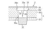
図9に示す例では、ラバーソール3の凹部3a(つまりミッドソール30の貫通孔30a)の底壁側領域には、硬質のアウトソール31を上方に挿通してアウトソール部32が設けられている。この場合には、運動時にスパイク26先端の下方への突き抜けが硬質のアウトソール部32によって防止されている。9 to 13 show a third modification of the present invention.
In the example shown in FIG. 9, an
また、図9に示す例では、ミッドソール30に形成される貫通孔30aの形状が前記実施例の図8に示すものとは異なっている。前記実施例では、貫通孔30aがスパイクソール2のボス部25を収容しつつ下方に直線状に延びるストレート穴であるのに対し、図9に示すものでは、ボス部25を収容する大径の座ぐり穴30a1と、その下方に形成され、スパイク26を収容する小径の貫通孔30a2とから構成されている。このため、図9に示す例では、座ぐり穴30a1の下端の段差部30a’によってスパイクソール2のボス部25の下面25aが支持されている。このようにボス部25を段差部30a’で支持することにより、運動時にスパイク26が下方に移動してその先端が凹部3aの底部に接近するのを抑制できる。なお、貫通孔30aは、スパイクソール2のボス部25を収容しつつ下方に直線状に延びるストレート穴であってもよい。In the example shown in FIG. 9, the shape of the through
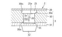
図10に示す例では、ラバーソール3の凹部3a(ミッドソール30の貫通孔30a)の底壁側領域に硬質プレート35が配設されている。硬質プレート35は、アウトソール31よりも硬度が高い素材(たとえば金属や硬質樹脂等)からなり、アウトソール31の上面に固着されている。この場合には、運動時に、仮にスパイク26の先端が凹部3aの底部に当接した場合でも、スパイク26先端が凹部3aの底部を突き抜けるのを硬質プレート35により防止できる。 In the example shown in FIG. 10, the
図11に示す例では、ミッドソール30に形成される貫通孔30aの形状が図10に示すものとは異なっている。図10では、貫通孔30aがスパイクソール2のボス部25を収容しつつ下方に直線状に延びるストレート穴であるのに対し、図11に示すものでは、ボス部25を収容する大径の座ぐり穴30a1と、その下方に形成され、スパイク26を収容する小径の貫通孔30a2とから構成されており、座ぐり穴30a1の下端の段差部30a’によってスパイクソール2のボス部25の下面25aが支持されている。このようにボス部25を段差部30a’で支持することにより、運動時にスパイク26が下方に移動してその先端が凹部3aの底部に接近するのを抑制できる。In the example shown in FIG. 11, the shape of the through
図12に示す例では、ラバーソール3の凹部3a(ミッドソール30の貫通孔30a)内に円筒状(リング状)の硬質部材36が設けられている。硬質部材36は、好ましくは、アウトソール31よりも硬度が高い素材(たとえば硬質ラバーや金属等)からなる。硬質部材36の中央の中空穴36aにはスパイク26が収容されており、上面はボス部25の下面25aを支持している。この場合には、運動時にスパイク26が下方に移動してその先端が凹部3aの底部に接近するのを硬質部材36により抑制できるとともに、仮にスパイク26の先端が凹部3aの底部に当接した場合でも、スパイク26先端が凹部3aの底部を突き抜けるのを硬質プレート35により防止できる。 In the example shown in FIG. 12, a cylindrical (ring-shaped)
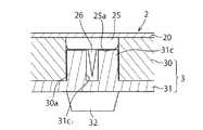
図13に示す例では、ラバーソール3の凹部3a(ミッドソール30の貫通孔30a)内に硬質のアウトソール31が上方に延設されており、当該延設部31cによって、図12の硬質部材36に相当するものが構成されている。延設部31cの中央の中空穴31c1内にはスパイク26が収容されており、延設部31cの上面はボス部25の下面25aを支持している。この場合には、運動時にスパイク26が下方に移動してその先端が凹部3aの底部に接近するのを延設部31cにより抑制できるとともに、仮にスパイク26の先端が凹部3aの底部に当接した場合でも、スパイク26先端が凹部3aの底部を突き抜けるのを硬質のアウトソール31(さらにはアウトソール部32)により防止できる。In the example shown in FIG. 13, a
<第4の変形例>
前記実施例では、ラバーソール3において、足部Sの前後方向中央部および後端側の締結具5としてBOA(登録商標)クロージャーシステムが採用された例を示したが、これは一般的なベルトによる締結具に代えてもよい。<Fourth Modification>
In the said Example, although the BOA (trademark) closure system was employ | adopted as the
図14は、締結具5として一般的なベルトを採用した例を示している。ここでは、競技用義足Lおよび足部Sが二点鎖線ではなく実線で示されている。また、スパイクソール2の立上げ部21の個数が前記実施例に示すものとは異なっている。 FIG. 14 shows an example in which a general belt is employed as the
図14に示すように、足部Sの前後方向中央部および後端側の締結具5として、前端側の締結具4のベルト40と同様に、面ファスナー付きベルト55が設けられている。なお、同図に示すものでは、前端側の締結具4におけるベルト40’が省略されている。 As shown in FIG. 14, a
<第5の変形例>
図15は、本発明によるミッドソールの変形例を示している。同図に示すように、ミッドソール30の貫通孔30aの上側開口の後端側縁部には、前後方向に延びるガイド溝30cが形成されている。これらのガイド溝30cは、ラバーソール3をスパイクソール2に取り付ける際にラバーソール3に対するスパイク26先端の移動を案内するためのものである。ガイド溝30cを設けることで、スパイクソール2のスパイク26をラバーソール3の凹部3aにスムーズに収容することができ、これにより、スパイクソール2に対するラバーソール3の取付けをスムーズに行えるようになる。<Fifth Modification>
FIG. 15 shows a modification of the midsole according to the present invention. As shown in the figure, a
<その他の変形例>
上述した実施例および各変形例はあらゆる点で本発明の単なる例示としてのみみなされるべきものであって、限定的なものではない。本発明が関連する分野の当業者は、本明細書中に明示の記載はなくても、上述の教示内容を考慮するとき、本発明の精神および本質的な特徴部分から外れることなく、本発明の原理を採用する種々の変形例やその他の実施例を構築し得る。<Other variations>
The above-described embodiments and modifications are to be regarded as merely illustrative of the present invention in all respects and are not limiting. Those skilled in the art to which the present invention pertains will not depart from the spirit and essential characteristics of the present invention without departing from the spirit and essential characteristics thereof, even if not explicitly stated herein. Various modifications and other embodiments employing the above principle can be constructed.
<他の適用例>
前記実施例では、本発明による義足用ソールシステムが競技用義足の足部(すなわちスポーツ義足)に適用された例を示したが、本発明の適用はこれに限定されるものではなく、本発明は、日常生活で使用される生活義足にも適用可能である。<Other application examples>
In the above embodiment, the example in which the sole system for a prosthetic limb according to the present invention is applied to a foot portion of a prosthetic limb for competition (that is, a sports prosthetic limb) is shown, but the application of the present invention is not limited to this. Can also be applied to life prostheses used in daily life.
以上のように、本発明は、義足用ソールシステムに有用であり、とくに、板ばね状の競技用義足の足部に取り付けられるソールシステムに適している。 As described above, the present invention is useful for a prosthetic sole system, and is particularly suitable for a sole system that is attached to a foot portion of a leaf prosthetic prosthetic leg.
1: 義足用ソールシステム
2: スパイクソール
20: スパイクソール本体部
21: 立上げ部
25: ボス部(スパイク取付部)
26: スパイク
3: ラバーソール
3a: 凹部
30: ミッドソール
30c: ガイド溝
31: アウトソール
4、5: 締結具
L: 競技用義足
S: 足部1: Prosthetic sole system
2: Spike sole 20: Spike sole body part 21: Rising part 25: Boss part (spike mounting part)
26: Spike
3: Rubber sole 3a: Recessed portion 30: Mid sole 30c: Guide groove 31: Outsole
4, 5: Fastener
L: Prosthetic leg for competition S: Foot
Claims (11)
Translated fromJapanese義足の下面に取り付けられるスパイクソールと、
前記スパイクソールの下方に配置され、義足に取外し可能に設けられるラバーソールと、
を備えた義足用ソールシステム。A sole system for a prosthetic leg,
A spike sole attached to the lower surface of the prosthesis,
A rubber sole that is disposed below the spike sole and is detachably provided on the artificial leg;
Prosthetic sole system with
前記ラバーソールの上面が、前記スパイクソールのスパイクまたはスパイク取付部を収容し得る凹部を有している、
ことを特徴とする義足用ソールシステム。In claim 1,
The upper surface of the rubber sole has a recess that can accommodate the spike or spike mounting portion of the spike sole.
Prosthetic sole system characterized by that.
前記ラバーソールの前記凹部において前記スパイクまたはスパイク取付部と対向する底壁側領域には、硬質領域が設けられている、
ことを特徴とする義足用ソールシステム。In claim 2,
A hard region is provided in the bottom wall side region facing the spike or spike mounting portion in the recess of the rubber sole.
Prosthetic sole system characterized by that.
前記ラバーソールの前記上面には、前記ラバーソールを前記スパイクソールに取り付ける際に前記スパイクの先端を前記凹部まで案内するガイド溝が形成されている、
ことを特徴とする義足用ソールシステム。In claim 2,
A guide groove is formed on the upper surface of the rubber sole to guide the tip of the spike to the recess when the rubber sole is attached to the spike sole.
Prosthetic sole system characterized by that.
前記ラバーソールが、義足に締結するための締結具を有している、
ことを特徴とする義足用ソールシステム。In claim 1,
The rubber sole has a fastener for fastening to a prosthetic leg,
Prosthetic sole system characterized by that.
前記ラバーソールが、前記スパイクソールに当接するミッドソールと、その下方に配置され、接地面を有するアウトソールとから構成されている、
ことを特徴とする義足用ソールシステム。In claim 1,
The rubber sole is composed of a midsole that comes into contact with the spike sole, and an outsole that is disposed below and has a ground contact surface.
Prosthetic sole system characterized by that.
前記ミッドソールおよびアウトソール間には、前記ラバーソールを義足に締結するための締結具の一端が挟持されている、
ことを特徴とする義足用ソールシステム。In claim 6,
Between the midsole and the outsole, one end of a fastener for fastening the rubber sole to the artificial leg is sandwiched,
Prosthetic sole system characterized by that.
前記スパイクソールが、義足の下面に装着されるスパイクソール本体部と、前記スパイクソール本体部の外周縁部から上方に立ち上がる立上げ部とを有している、
ことを特徴とする義足用ソールシステム。In claim 1,
The spike sole has a spike sole main body mounted on the lower surface of the prosthetic leg and a rising portion that rises upward from an outer peripheral edge of the spike sole main body.
Prosthetic sole system characterized by that.
前記立上げ部が、前記スパイクソール本体部の前記外周縁部の複数の個所に設けられている、
ことを特徴とする義足用ソールシステム。In claim 8,
The rising portion is provided at a plurality of locations on the outer peripheral edge of the spike sole body.
Prosthetic sole system characterized by that.
前記ラバーソールが義足に締結するための締結具を有しており、前記締結具が前記立上げ部によって係止されている、
ことを特徴とする義足用ソールシステム。In claim 8,
The rubber sole has a fastener for fastening to a prosthetic leg, and the fastener is locked by the rising portion.
Prosthetic sole system characterized by that.
当該ソールシステムが、湾曲した板ばね状の競技用義足の足部に取り付けられるようになっている、
ことを特徴とする義足用ソールシステム。In claim 1,
The sole system is adapted to be attached to a foot portion of a curved leaf spring-like competition artificial leg.
Prosthetic sole system characterized by that.
Priority Applications (2)
| Application Number | Priority Date | Filing Date | Title |
|---|---|---|---|
| JP2015030356AJP6511214B2 (en) | 2015-02-19 | 2015-02-19 | Prosthetic sole system |
| PCT/JP2016/053421WO2016132927A1 (en) | 2015-02-19 | 2016-02-04 | Sole system for leg prostheses |
Applications Claiming Priority (1)
| Application Number | Priority Date | Filing Date | Title |
|---|---|---|---|
| JP2015030356AJP6511214B2 (en) | 2015-02-19 | 2015-02-19 | Prosthetic sole system |
Publications (2)
| Publication Number | Publication Date |
|---|---|
| JP2016150189Atrue JP2016150189A (en) | 2016-08-22 |
| JP6511214B2 JP6511214B2 (en) | 2019-05-15 |
Family
ID=56692294
Family Applications (1)
| Application Number | Title | Priority Date | Filing Date |
|---|---|---|---|
| JP2015030356AActiveJP6511214B2 (en) | 2015-02-19 | 2015-02-19 | Prosthetic sole system |
Country Status (2)
| Country | Link |
|---|---|
| JP (1) | JP6511214B2 (en) |
| WO (1) | WO2016132927A1 (en) |
Cited By (13)
| Publication number | Priority date | Publication date | Assignee | Title |
|---|---|---|---|---|
| WO2019203282A1 (en)* | 2018-04-17 | 2019-10-24 | 株式会社ブリヂストン | Sole for sports artificial foot |
| WO2019203283A1 (en)* | 2018-04-17 | 2019-10-24 | 株式会社ブリヂストン | Sole for sports artificial foot |
| WO2019203286A1 (en) | 2018-04-17 | 2019-10-24 | 株式会社ブリヂストン | Sole for sports artificial foot |
| WO2019203289A1 (en) | 2018-04-17 | 2019-10-24 | 株式会社ブリヂストン | Sole for sports artificial foot |
| WO2019203287A1 (en)* | 2018-04-17 | 2019-10-24 | 株式会社ブリヂストン | Sole for sports artificial foot |
| WO2019203288A1 (en)* | 2018-04-17 | 2019-10-24 | 株式会社ブリヂストン | Sole for sports artificial foot |
| WO2020017663A1 (en) | 2018-07-20 | 2020-01-23 | 株式会社ブリヂストン | Sole for artificial feet |
| WO2020022292A1 (en)* | 2018-07-24 | 2020-01-30 | 株式会社ブリヂストン | Sole for athletic prosthetic leg |
| WO2020022276A1 (en) | 2018-07-24 | 2020-01-30 | 株式会社ブリヂストン | Sole for prosthetic leg |
| WO2020022277A1 (en) | 2018-07-24 | 2020-01-30 | 株式会社ブリヂストン | Sole for athletic prosthetic leg |
| WO2020022275A1 (en)* | 2018-07-24 | 2020-01-30 | 株式会社ブリヂストン | Sole for athletic prosthetic leg |
| WO2021202071A1 (en)* | 2020-04-03 | 2021-10-07 | Nike Innovate C.V. | Traction system for an ambulatory support |
| CN114340564A (en)* | 2019-09-02 | 2022-04-12 | 株式会社普利司通 | The sole of a prosthetic foot |
Families Citing this family (3)
| Publication number | Priority date | Publication date | Assignee | Title |
|---|---|---|---|---|
| JP7026599B2 (en)* | 2018-09-28 | 2022-02-28 | 株式会社アシックス | Sole for prosthesis |
| JP7330237B2 (en) | 2020-07-23 | 2023-08-21 | プーマ エス イー | Sole structures, footwear devices and assemblies |
| CN114788596A (en)* | 2022-05-17 | 2022-07-26 | 北京服装学院 | 3D printing nail shoe of steel frame snowmobile |
Citations (7)
| Publication number | Priority date | Publication date | Assignee | Title |
|---|---|---|---|---|
| JPS49112451U (en)* | 1973-01-19 | 1974-09-26 | ||
| JPS59101805U (en)* | 1982-12-27 | 1984-07-09 | 川内 武男 | Cover for golf shoes |
| JPS6313003U (en)* | 1986-07-14 | 1988-01-28 | ||
| JPH0518301U (en)* | 1991-08-28 | 1993-03-09 | 美津濃株式会社 | Overshoes of track and field shoes used for track competition |
| JPH08317806A (en)* | 1995-05-25 | 1996-12-03 | Asics Corp | Spike shoes |
| US5593456A (en)* | 1994-05-17 | 1997-01-14 | Crp, Inc. | Foot and leg prosthesis and method of making same |
| US8535390B1 (en)* | 2011-09-16 | 2013-09-17 | össur hf | Traction device and associated attachment device for a prosthetic running foot |
- 2015
- 2015-02-19JPJP2015030356Apatent/JP6511214B2/enactiveActive
- 2016
- 2016-02-04WOPCT/JP2016/053421patent/WO2016132927A1/ennot_activeCeased
Patent Citations (7)
| Publication number | Priority date | Publication date | Assignee | Title |
|---|---|---|---|---|
| JPS49112451U (en)* | 1973-01-19 | 1974-09-26 | ||
| JPS59101805U (en)* | 1982-12-27 | 1984-07-09 | 川内 武男 | Cover for golf shoes |
| JPS6313003U (en)* | 1986-07-14 | 1988-01-28 | ||
| JPH0518301U (en)* | 1991-08-28 | 1993-03-09 | 美津濃株式会社 | Overshoes of track and field shoes used for track competition |
| US5593456A (en)* | 1994-05-17 | 1997-01-14 | Crp, Inc. | Foot and leg prosthesis and method of making same |
| JPH08317806A (en)* | 1995-05-25 | 1996-12-03 | Asics Corp | Spike shoes |
| US8535390B1 (en)* | 2011-09-16 | 2013-09-17 | össur hf | Traction device and associated attachment device for a prosthetic running foot |
Cited By (28)
| Publication number | Priority date | Publication date | Assignee | Title |
|---|---|---|---|---|
| JP7288897B2 (en) | 2018-04-17 | 2023-06-08 | 株式会社ブリヂストン | Athletic prosthesis sole |
| JP7201671B2 (en) | 2018-04-17 | 2023-01-10 | 株式会社ブリヂストン | Athletic prosthesis sole |
| WO2019203286A1 (en) | 2018-04-17 | 2019-10-24 | 株式会社ブリヂストン | Sole for sports artificial foot |
| WO2019203289A1 (en) | 2018-04-17 | 2019-10-24 | 株式会社ブリヂストン | Sole for sports artificial foot |
| WO2019203287A1 (en)* | 2018-04-17 | 2019-10-24 | 株式会社ブリヂストン | Sole for sports artificial foot |
| WO2019203288A1 (en)* | 2018-04-17 | 2019-10-24 | 株式会社ブリヂストン | Sole for sports artificial foot |
| WO2019203283A1 (en)* | 2018-04-17 | 2019-10-24 | 株式会社ブリヂストン | Sole for sports artificial foot |
| US12042407B2 (en) | 2018-04-17 | 2024-07-23 | Bridgestone Corporation | Sole of athletic prosthetic leg |
| JPWO2019203282A1 (en)* | 2018-04-17 | 2021-04-30 | 株式会社ブリヂストン | Competition prosthesis sole |
| WO2019203282A1 (en)* | 2018-04-17 | 2019-10-24 | 株式会社ブリヂストン | Sole for sports artificial foot |
| JP7201670B2 (en) | 2018-04-17 | 2023-01-10 | 株式会社ブリヂストン | Athletic prosthesis sole |
| JP7199424B2 (en) | 2018-04-17 | 2023-01-05 | 株式会社ブリヂストン | Athletic prosthesis sole |
| JPWO2019203288A1 (en)* | 2018-04-17 | 2021-05-13 | 株式会社ブリヂストン | Competition prosthesis sole |
| JPWO2019203283A1 (en)* | 2018-04-17 | 2021-04-22 | 株式会社ブリヂストン | Competition prosthesis sole |
| JPWO2019203286A1 (en)* | 2018-04-17 | 2021-04-22 | 株式会社ブリヂストン | Competition prosthesis sole |
| JPWO2019203287A1 (en)* | 2018-04-17 | 2021-04-30 | 株式会社ブリヂストン | Competition prosthesis sole |
| JP2020010998A (en)* | 2018-07-20 | 2020-01-23 | 株式会社ブリヂストン | Prosthetic sole |
| CN112437652A (en)* | 2018-07-20 | 2021-03-02 | 株式会社普利司通 | Sole for artificial foot |
| WO2020017663A1 (en) | 2018-07-20 | 2020-01-23 | 株式会社ブリヂストン | Sole for artificial feet |
| JPWO2020022276A1 (en)* | 2018-07-24 | 2021-08-02 | 株式会社ブリヂストン | Prosthesis sole |
| WO2020022275A1 (en)* | 2018-07-24 | 2020-01-30 | 株式会社ブリヂストン | Sole for athletic prosthetic leg |
| WO2020022277A1 (en) | 2018-07-24 | 2020-01-30 | 株式会社ブリヂストン | Sole for athletic prosthetic leg |
| WO2020022276A1 (en) | 2018-07-24 | 2020-01-30 | 株式会社ブリヂストン | Sole for prosthetic leg |
| WO2020022292A1 (en)* | 2018-07-24 | 2020-01-30 | 株式会社ブリヂストン | Sole for athletic prosthetic leg |
| JP7364566B2 (en) | 2018-07-24 | 2023-10-18 | 株式会社ブリヂストン | prosthetic sole |
| CN114340564A (en)* | 2019-09-02 | 2022-04-12 | 株式会社普利司通 | The sole of a prosthetic foot |
| WO2021202071A1 (en)* | 2020-04-03 | 2021-10-07 | Nike Innovate C.V. | Traction system for an ambulatory support |
| CN115361926A (en)* | 2020-04-03 | 2022-11-18 | 耐克创新有限合伙公司 | Traction system for mobile supports |
Also Published As
| Publication number | Publication date |
|---|---|
| JP6511214B2 (en) | 2019-05-15 |
| WO2016132927A1 (en) | 2016-08-25 |
Similar Documents
| Publication | Publication Date | Title |
|---|---|---|
| JP6511214B2 (en) | Prosthetic sole system | |
| US12144391B2 (en) | Walking device | |
| US7984569B2 (en) | Modular footwear system | |
| US12342906B2 (en) | Adjustable closure system for an article | |
| US8800171B1 (en) | Footwear insole system | |
| US8813391B1 (en) | Footwear with insole system | |
| US10681955B2 (en) | Interchangeable sole system | |
| US6029376A (en) | Article of footwear | |
| EP1603739B1 (en) | Toe protection sandal | |
| US9113675B2 (en) | Article of footwear | |
| CN108354264B (en) | Article of footwear with sole structure | |
| EP1802211B1 (en) | Article of footwear with upper support assembly | |
| US20070240333A1 (en) | Chassis for footwear and method of making footwear | |
| US8448356B2 (en) | Article of footwear for riding | |
| US20110302805A1 (en) | Adjustable and interchangebale insole and arch support system | |
| US20110179669A1 (en) | Cushioning and shock absorbing midsole | |
| US20210112918A1 (en) | Footwear sole assembly | |
| US20200268099A1 (en) | Modular orthotic footwear system | |
| JP5002170B2 (en) | Sole material and fishing shoes | |
| CA2588320C (en) | Modular footwear system | |
| US20190069640A1 (en) | Shoes | |
| JP2004160064A (en) | Fishing boots | |
| KR102647826B1 (en) | Shoes capable of supporting the arch of the sole and method for manufacturing the same | |
| JP4877704B2 (en) | Sole material and fishing shoes | |
| US10765916B2 (en) | Swim Shoe |
Legal Events
| Date | Code | Title | Description |
|---|---|---|---|
| A621 | Written request for application examination | Free format text:JAPANESE INTERMEDIATE CODE: A621 Effective date:20170614 | |
| A131 | Notification of reasons for refusal | Free format text:JAPANESE INTERMEDIATE CODE: A131 Effective date:20180406 | |
| A521 | Request for written amendment filed | Free format text:JAPANESE INTERMEDIATE CODE: A523 Effective date:20180519 | |
| A131 | Notification of reasons for refusal | Free format text:JAPANESE INTERMEDIATE CODE: A131 Effective date:20181023 | |
| A521 | Request for written amendment filed | Free format text:JAPANESE INTERMEDIATE CODE: A523 Effective date:20181116 | |
| TRDD | Decision of grant or rejection written | ||
| A01 | Written decision to grant a patent or to grant a registration (utility model) | Free format text:JAPANESE INTERMEDIATE CODE: A01 Effective date:20190312 | |
| A61 | First payment of annual fees (during grant procedure) | Free format text:JAPANESE INTERMEDIATE CODE: A61 Effective date:20190406 | |
| R150 | Certificate of patent or registration of utility model | Ref document number:6511214 Country of ref document:JP Free format text:JAPANESE INTERMEDIATE CODE: R150 | |
| R250 | Receipt of annual fees | Free format text:JAPANESE INTERMEDIATE CODE: R250 | |
| R250 | Receipt of annual fees | Free format text:JAPANESE INTERMEDIATE CODE: R250 |