JP2016148968A - Head-mounted display device, control system, method for controlling head-mounted display device, and computer program - Google Patents
Head-mounted display device, control system, method for controlling head-mounted display device, and computer programDownload PDFInfo
- Publication number
- JP2016148968A JP2016148968AJP2015024971AJP2015024971AJP2016148968AJP 2016148968 AJP2016148968 AJP 2016148968AJP 2015024971 AJP2015024971 AJP 2015024971AJP 2015024971 AJP2015024971 AJP 2015024971AJP 2016148968 AJP2016148968 AJP 2016148968A
- Authority
- JP
- Japan
- Prior art keywords
- image
- unit
- control
- head
- display device
- Prior art date
- Legal status (The legal status is an assumption and is not a legal conclusion. Google has not performed a legal analysis and makes no representation as to the accuracy of the status listed.)
- Granted
Links
Images


Landscapes
- User Interface Of Digital Computer (AREA)
Abstract
Description
Translated fromJapanese本発明は、頭部装着型表示装置の技術に関する。 The present invention relates to a head-mounted display device.
頭部に装着する表示装置である頭部装着型表示装置(ヘッドマウントディスプレイ(Head Mounted Display)、HMD)が知られている。頭部装着型表示装置は、例えば、液晶ディスプレイおよび光源を利用して画像を表わす画像光を生成し、生成された画像光を投写光学系や導光板を利用して使用者の眼に導くことにより、使用者に虚像を視認させる。頭部装着型表示装置には、使用者が虚像に加えて外景も視認可能な透過型と、使用者が外景を視認できない非透過型と、の2つのタイプがある。透過型の頭部装着型表示装置には、光学透過型とビデオ透過型とがある。 A head-mounted display device (Head Mounted Display, HMD) that is a display device mounted on the head is known. The head-mounted display device, for example, generates image light representing an image using a liquid crystal display and a light source, and guides the generated image light to a user's eye using a projection optical system or a light guide plate This causes the user to visually recognize the virtual image. There are two types of head-mounted display devices: a transmission type in which the user can visually recognize the outside scene in addition to a virtual image, and a non-transmission type in which the user cannot visually recognize the outside scene. The transmissive head-mounted display device includes an optical transmissive type and a video transmissive type.
特許文献1には、コントローラーから送信された制御コマンドを受信する被制御機器が受信した制御コマンドに関する表示制御データをコントローラーに送信することで、コントローラーと被制御機器との双方向のデータの送受信が行なわれる機器制御システムについて開示されている。特許文献2には、撮像した使用者の視野と同等以上の範囲に、所定のマークとしての使用者の指先が含まれている場合に、指先の座標値を出力することで、指先の位置に応じた制御処理を行なう入力画像処理方法について開示されている。特許文献3には、2眼カメラによって撮像された外景と撮像された使用者の手の位置および姿勢とに基づいて、被制御機器を操作する情報入力方法について開示されている。 In
しかし、特許文献1に記載された技術では、複数の被制御機器が存在する場合に、使用者がいずれの被制御機器を制御するために、直感的な操作による制御を行なうことができず、使い勝手を向上させたいという課題があった。また、特許文献2に記載された技術では、使用者は、対象となる被制御機器を選択するまで指先の位置を固定し続ける必要があり、使用者の疲労を招くため、さらに使い勝手を向上させたいという課題があった。また、特許文献3では、手の位置と姿勢とに基づいて被制御機器が操作されるが、それ以外の情報も加味して被制御機器を操作することでより直感的に被制御機器を操作したいという課題があった。 However, in the technique described in
本発明は、上述の課題の少なくとも一部を解決するためになされたものであり、以下の形態として実現することが可能である。 SUMMARY An advantage of some aspects of the invention is to solve at least a part of the problems described above, and the invention can be implemented as the following forms.
(1)本発明の一形態によれば、透過型の頭部装着型表示装置が提供される。この頭部装着型表示装置は、虚像を表示し、外景を透過可能な画像表示部と;前記画像表示部から所定の距離の範囲にある選択可能な対象物と、前記外景に含まれる特定のオブジェクトの位置と、を取得する対象取得部と;取得された前記対象物に対応付けられている対象物対応虚像を、前記画像表示部を用いて前記虚像として表示し、取得された前記特定のオブジェクトの位置に基づいて前記特定のオブジェクトの位置の変化を特定し、特定した前記特定のオブジェクトの位置の変化と取得された前記対象物の位置との関係に基づいて前記対象物を選択し、選択した前記対象物に対応付けられている特定確認画像を、前記画像表示部を用いて前記虚像として表示する制御部と、を備える。この形態の頭部装着型表示装置によれば、使用者は、操作する対象の対象物と検出された特定のオブジェクトの位置の変化に対応付けられた制御とを視線方向を変えないで同時に視認でき、対象物の制御を直感的に行なうことができ、使用者の利便性が向上する。(1) According to one aspect of the present invention, a transmissive head-mounted display device is provided. The head-mounted display device includes an image display unit that displays a virtual image and can transmit an outside scene; a selectable object within a predetermined distance from the image display unit; and a specific object included in the outside scene A target acquisition unit that acquires the position of the object; an object-corresponding virtual image associated with the acquired target object is displayed as the virtual image using the image display unit, and the specific image acquired Identifying a change in the position of the specific object based on the position of the object, selecting the target based on the relationship between the change in the position of the specified specific object identified and the position of the acquired object; A control unit that displays the specific confirmation image associated with the selected object as the virtual image using the image display unit. According to the head-mounted display device of this aspect, the user can simultaneously view the target object to be operated and the control associated with the change in the position of the detected specific object without changing the line-of-sight direction. It is possible to control the object intuitively, and the convenience for the user is improved.
(2)上記形態の頭部装着型表示装置において、前記対象取得部は、前記外景を撮像する撮像部と、撮像された前記外景の中に含まれる前記特定のオブジェクトの位置と前記対象物とを検出して取得する画像検出部と、を有し;前記制御部は、選択した前記対象物の制御を決定し、決定した前記対象物の制御を実行してもよい。この形態の頭部装着型表示装置によれば、撮像することにより特定のオブジェクトおよび対象物を取得でき、同時に、使用者は、撮像された特定のオブジェクトおよび対象物を視認できるため、対象物を認識しやすい。(2) In the head-mounted display device according to the above aspect, the target acquisition unit includes an imaging unit that images the outside scene, the position of the specific object included in the captured outside scene, and the target object. An image detecting unit that detects and acquires the image; and the control unit may determine control of the selected object and execute control of the determined object. According to the head-mounted display device of this aspect, it is possible to acquire a specific object and target object by capturing an image, and at the same time, the user can visually recognize the captured specific object and target object. Easy to recognize.
(3)上記形態の頭部装着型表示装置において、前記制御部は、取得された前記特定のオブジェクトの位置と取得された前記対象物との組み合わせに予め対応付けられている前記対象物対応虚像を、前記画像表示部を用いて前記虚像として表示してもよい。この形態の頭部装着型表示装置によれば、使用者は、対象物の制御を実行するために必要な特定のオブジェクトの位置の変化を視覚情報として認識でき、使用者にとっての頭部装着型表示装置の使い勝手が向上する。(3) In the head-mounted display device of the above aspect, the control unit is configured to associate the target corresponding virtual image with a combination of the acquired position of the specific object and the acquired target. May be displayed as the virtual image using the image display unit. According to the head-mounted display device of this form, the user can recognize the change in the position of a specific object necessary for executing the control of the target object as visual information. Usability of the display device is improved.
(4)上記形態の頭部装着型表示装置において、前記制御部は、取得された前記特定のオブジェクトの位置と取得された前記対象物との組み合わせに予め対応付けられている前記対象物対応虚像として、前記対象物の制御を実行するために必要な前記特定のオブジェクトの位置の変化を示す前記虚像を、前記画像表示部を用いて表示してもよい。この形態の頭部装着型表示装置によれば、使用者が自身の特定のオブジェクトの位置の変化に対応して次に実行される対象物の制御の内容を視覚情報として認識できるので、使用者にとっての使い勝手が向上する。(4) In the head-mounted display device of the above aspect, the control unit is configured to associate the target corresponding virtual image with a combination of the acquired position of the specific object and the acquired target. As another example, the virtual image indicating a change in the position of the specific object necessary for executing the control of the object may be displayed using the image display unit. According to the head-mounted display device of this aspect, the user can recognize the content of the control of the object to be executed next in response to the change in the position of the specific object of the user as visual information. Usability for the user is improved.
(5)上記形態の頭部装着型表示装置において、前記制御部は、取得された前記対象物に予め対応付けられている前記対象物対応虚像として、実行する前記対象物の制御の内容を示す前記虚像を、前記画像表示部を用いて表示してもよい。この形態の頭部装着型表示装置によれば、使用者が特定のオブジェクトの位置の変化に対応して次に実行される対象物の制御の内容を視覚情報として認識できるので、使用者にとっての使い勝手が向上する。(5) In the head-mounted display device according to the above aspect, the control unit indicates the content of control of the object to be executed as the object-corresponding virtual image associated in advance with the acquired object. The virtual image may be displayed using the image display unit. According to the head-mounted display device of this form, the user can recognize the contents of the control of the object to be executed next in response to the change in the position of the specific object as visual information. Usability is improved.
(6)上記形態の頭部装着型表示装置において、前記制御部は、撮像された前記外景において、前記特定のオブジェクトの変化後の位置と前記対象物とが重なっている場合に、前記特定のオブジェクトの変化後の位置と重なっている前記対象物に予め対応付けられている前記対象物の制御を決定してもよい。この形態の頭部装着型表示装置によれば、特定のオブジェクトの位置の変化後に特定のオブジェクトが重なっている対象物に対応する対象物の制御が実行されるため、使用者は、意図した対象物の制御に対応する特定のオブジェクトの変化を行ないやすい。(6) In the head-mounted display device according to the above aspect, the control unit may detect the specific object when the position after the change of the specific object overlaps the target object in the captured outside scene. You may determine control of the said object previously matched with the said target object which overlaps with the position after the change of an object. According to the head-mounted display device of this aspect, since the control of the target object corresponding to the target object on which the specific object overlaps is executed after the position of the specific object is changed, the user can It is easy to change a specific object corresponding to the control of an object.
(7)上記形態の頭部装着型表示装置において、さらに;取得された前記対象物と前記画像表示部との距離を特定する距離特定部を備え;前記制御部は、取得されると共に特定された前記距離が閾値以下の前記対象物を、選択可能な前記対象物として設定してもよい。この形態の頭部装着型表示装置によれば、撮像された画像に複数の仮対象が検出された場合に、使用者から近いものを選択可能な対象物として設定するので、使用者に選択される可能性の高い対象物を使用者に視認させるため、使用者の利便性が向上する。(7) The head-mounted display device according to the above aspect further includes: a distance specifying unit that specifies a distance between the acquired object and the image display unit; and the control unit is acquired and specified. Alternatively, the object whose distance is equal to or less than a threshold value may be set as the selectable object. According to the head-mounted display device of this aspect, when a plurality of temporary objects are detected in the captured image, an object close to the user is set as a selectable object, so that it is selected by the user. Therefore, the convenience of the user is improved because the user can visually recognize an object that is likely to be displayed.
(8)上記形態の頭部装着型表示装置において、さらに;外部の音声を取得する音声取得部を備え;前記制御部は、特定された前記特定のオブジェクトの位置の変化と取得された前記音声との組み合わせに基づいて前記対象物の制御を決定してもよい。この形態の頭部装着型表示装置によれば、特定のオブジェクトの位置の変化と音声との組み合わせによって対象物の制御が実行されるため、特定のオブジェクトの位置の変化のみによって実行される対象物の制御よりも、使用者は、より多くの対象物の制御を直感的に行なうことができる。(8) The head-mounted display device according to the above aspect further includes: an audio acquisition unit that acquires external audio; the control unit is configured to change the position of the specified object and the acquired audio The control of the object may be determined based on the combination. According to the head-mounted display device of this aspect, since the control of the target object is executed by the combination of the change in the position of the specific object and the sound, the target object that is executed only by the change in the position of the specific object The user can intuitively control more objects than the above control.
(9)上記形態の頭部装着型表示装置において、前記対象取得部は、他の装置から少なくとも1つの前記対象物の位置情報を取得してもよい。この形態の頭部装着型表示装置によれば、使用者が視認できない範囲の選択可能な対象物の位置も認識でき、使用者の使い勝手が向上する。(9) In the head mounted display device according to the above aspect, the target acquisition unit may acquire position information of at least one of the objects from another device. According to the head-mounted display device of this form, the position of a selectable object in a range that cannot be visually recognized by the user can also be recognized, and the convenience of the user is improved.
(10)上記形態の頭部装着型表示装置において、前記制御部は、取得された前記対象物が前記外景に含まれない場合に、前記画像表示部を用いて、前記画像表示部と取得された前記対象物との位置関係を前記虚像として表示してもよい。この形態の頭部装着型表示装置によれば、使用者が視認できない範囲の選択可能な対象物の位置と使用者との位置関係を虚像として視認でき、使用者の使い勝手がより向上する。(10) In the head-mounted display device of the above aspect, the control unit is acquired from the image display unit using the image display unit when the acquired object is not included in the outside scene. The positional relationship with the object may be displayed as the virtual image. According to the head-mounted display device of this form, the positional relationship between the user and the position of the selectable object that cannot be visually recognized by the user can be visually recognized as a virtual image, and the usability of the user is further improved.
(11)上記形態の頭部装着型表示装置において、前記制御部は、前記特定のオブジェクトの加速度を検出し、検出した前記特定のオブジェクトの加速度に基づいて、前記特定のオブジェクトの位置の変化を特定してもよい。この形態の頭部装着型表示装置によれば、使用者が選択した対象物への制御指示を実行する場合に、特定の場所を操作したり、操作として対応付けられ動作を撮像される範囲で行なう必要がなく、使用者の利便性が向上する。(11) In the head-mounted display device of the above aspect, the control unit detects an acceleration of the specific object, and changes a position of the specific object based on the detected acceleration of the specific object. You may specify. According to the head-mounted display device of this embodiment, when executing a control instruction to an object selected by the user, the user can operate a specific place, or can be associated with the operation as long as the operation is imaged. There is no need to do so, and convenience for the user is improved.
(12)上記形態の頭部装着型表示装置において、さらに;外部の音声を取得する音声取得部を備え;前記制御部は、取得された前記外部の音声と、特定された前記特定のオブジェクトの位置の変化との組み合わせに基づいて、選択した前記対象物の制御を決定してもよい。この形態の頭部装着型表示装置によれば、音声と特定のオブジェクトの位置の変化との複数の要素に基づいて、選択された対象物への制御が決定されるため、使用者がより多くの操作を入力でき、使用者の使い勝手が向上する。(12) The head-mounted display device according to the above aspect further includes: an audio acquisition unit that acquires external audio; and the control unit is configured to acquire the acquired external audio and the specified specific object. Control of the selected object may be determined based on a combination with a change in position. According to the head-mounted display device of this aspect, since control to the selected target object is determined based on a plurality of elements including sound and a change in position of a specific object, more users are used. The user's convenience is improved.
(13)上記形態の頭部装着型表示装置において、前記制御部は、選択した前記対象物に対応付けられた制御装置の制御を実行し、前記外景に選択した前記対象物と前記制御装置とが取得される場合に、前記画像表示部を用いて、選択した前記対象物と前記制御装置とが対応関係にあることを前記虚像として表示してもよい。この形態の頭部装着型表示装置によれば、検出された選択可能な対象物と検出された特定のオブジェクトとの対応関係を視認させることができ、使用者の使い勝手が向上する。(13) In the head-mounted display device of the above aspect, the control unit executes control of a control device associated with the selected object, and the object selected as the outside scene and the control device May be displayed as the virtual image that the selected object and the control device are in a correspondence relationship using the image display unit. According to the head-mounted display device of this aspect, the correspondence relationship between the detected selectable target object and the detected specific object can be visually recognized, and the convenience for the user is improved.
(14)上記形態の頭部装着型表示装置において、前記制御部は、選択した前記対象物と前記制御装置とが対応関係にあることを示す前記虚像として、前記画像表示部を用いて、同じ形で同じ色の虚像を表示してもよい。この形態の頭部装着型表示装置によれば、検出された選択可能な対象物と検出された特定のオブジェクトとの対応関係をより明確に視認させることができ、使用者の使い勝手が向上する。(14) In the head-mounted display device according to the above aspect, the control unit uses the image display unit as the virtual image indicating that the selected target object and the control device are in a correspondence relationship. A virtual image of the same color may be displayed. According to the head-mounted display device of this aspect, the correspondence relationship between the detected selectable target object and the detected specific object can be more clearly recognized, and the convenience for the user is improved.
(15)上記形態の頭部装着型表示装置において、さらに;前記画像表示部の使用者の属性を識別する識別部を備え;前記制御部は、前記対象物に対応付けられている虚像と前記特定確認画像との少なくとも一方を、識別された前記属性に対応させて前記画像表示部を用いて前記虚像として表示してもよい。この形態の頭部装着型表示装置によれば、特定された使用者ごとに異なる虚像が画像表示部に生成されるため、使用者のニーズにあった情報を提供できる。(15) The head-mounted display device according to the above aspect may further include: an identification unit that identifies an attribute of a user of the image display unit; and the control unit may include a virtual image associated with the object and the virtual image At least one of the specific confirmation image may be displayed as the virtual image using the image display unit in association with the identified attribute. According to this form of the head-mounted display device, different virtual images are generated in the image display unit for each identified user, so that information that meets the needs of the user can be provided.
上述した本発明の各形態の有する複数の構成要素はすべてが必須のものではなく、上述の課題の一部または全部を解決するため、あるいは、本明細書に記載された効果の一部または全部を達成するために、適宜、前記複数の構成要素の一部の構成要素について、その変更、削除、新たな他の構成要素との差し替え、限定内容の一部削除を行なうことが可能である。また、上述の課題の一部または全部を解決するため、あるいは、本明細書に記載された効果の一部または全部を達成するために、上述した本発明の一形態に含まれる技術的特徴の一部または全部を上述した本発明の他の形態に含まれる技術的特徴の一部または全部と組み合わせて、本発明の独立した一形態とすることも可能である。 A plurality of constituent elements of each embodiment of the present invention described above are not essential, and some or all of the effects described in the present specification are to be solved to solve part or all of the above-described problems. In order to achieve the above, it is possible to appropriately change, delete, replace with another new component, and partially delete the limited contents of some of the plurality of components. In order to solve some or all of the above-described problems or achieve some or all of the effects described in this specification, technical features included in one embodiment of the present invention described above. A part or all of the technical features included in the other aspects of the present invention described above may be combined to form an independent form of the present invention.
例えば、本発明の一形態は、画像表示部と、対象取得部と、制御部と、の3つ要素の内の一部または全部の要素を備えた装置として実現可能である。すなわち、この装置は、画像表示部を有していてもよく、有していなくてもよい。また、装置は、対象取得部を有していてもよく、有していなくてもよい。また、装置は、制御部を有していてもよく、有していなくてもよい。画像表示部は、例えば、虚像を表示し、外景を透過可能であってもよい。対象検出部は、例えば、前記画像表示部から所定の距離の範囲にある選択可能な対象物と、前記外景に含まれる特定のオブジェクトの位置と、を取得してもよい。制御部は、例えば、取得された前記対象物に対応付けられている対象物対応虚像を、前記画像表示部を用いて前記虚像として表示し、取得された前記特定のオブジェクトの位置に基づいて前記特定のオブジェクトの位置を特定し、特定した前記特定のオブジェクトの位置の変化と取得された前記対象物の位置との関係に基づいて前記対象物を選択し、選択した前記対象物に対応付けられている特定確認画像を、前記画像表示部を用いて前記虚像として表示してもよい。こうした装置は、例えば、頭部装着型表示装置として実現できるが、頭部装着型表示装置以外の他の装置としても実現可能である。このような形態によれば、装置の操作性の向上および簡易化、装置の一体化や、装置を使用する使用者の利便性の向上、等の種々の課題の少なくとも1つを解決することができる。前述した頭部装着型表示装置の各形態の技術的特徴の一部または全部は、いずれもこの装置に適用することが可能である。 For example, one embodiment of the present invention can be realized as an apparatus including some or all of the three elements of the image display unit, the target acquisition unit, and the control unit. That is, this apparatus may or may not have an image display unit. Moreover, the apparatus may or may not have the target acquisition unit. The device may or may not have a control unit. For example, the image display unit may display a virtual image and transmit the outside scene. The target detection unit may acquire, for example, a selectable target within a predetermined distance from the image display unit and a position of a specific object included in the outside scene. The control unit displays, for example, a target corresponding virtual image associated with the acquired target as the virtual image using the image display unit, and based on the acquired position of the specific object, The position of the specific object is specified, the target is selected based on the relationship between the change in the position of the specified specific object and the acquired position of the target, and is associated with the selected target The specific confirmation image may be displayed as the virtual image using the image display unit. Such a device can be realized as, for example, a head-mounted display device, but can also be realized as a device other than the head-mounted display device. According to such a form, it is possible to solve at least one of various problems such as improvement and simplification of the operability of the device, integration of the device, and improvement of convenience of the user who uses the device. it can. Any or all of the technical features of each form of the head-mounted display device described above can be applied to this device.
本発明は、頭部装着型表示装置以外の種々の形態で実現することも可能である。例えば、表示装置、頭部装着型表示装置および表示装置の制御方法、制御システム、頭部装着型表示システム、表示装置、制御システムおよび表示装置の機能を実現するためのコンピュータープログラム、そのコンピュータープログラムを記録した記録媒体、そのコンピュータープログラムを含み搬送波内に具現化されたデータ信号等の形態で実現できる。 The present invention can also be realized in various forms other than the head-mounted display device. For example, a display device, a head-mounted display device, a control method for the display device, a control system, a head-mounted display system, a display device, a computer program for realizing the functions of the control system and the display device, and the computer program It can be realized in the form of a recorded recording medium, a data signal including the computer program and embodied in a carrier wave.
次に、本発明の実施の形態を実施形態に基づいて以下の順序で説明する。
A.第1実施形態:
A−1.頭部装着型表示装置の構成:
A−2.機器確認処理:
B.第2実施形態:
C.第3実施形態:
D.変形例:Next, embodiments of the present invention will be described in the following order based on the embodiments.
A. First embodiment:
A-1. Configuration of head mounted display device:
A-2. Device confirmation processing:
B. Second embodiment:
C. Third embodiment:
D. Variations:
A.第1実施形態:
A−1.頭部装着型表示装置の構成:
図1は、頭部装着型表示装置100(HMD100)の外観構成を示す説明図である。HMD100は、頭部に装着する表示装置であり、ヘッドマウントディスプレイ(Head Mounted Display、HMD)とも呼ばれる。本実施形態のHMD100は、使用者が、虚像を視認すると同時に外景も直接視認可能な光学透過型の頭部装着型表示装置である。なお、本明細書では、HMD100によって使用者が視認する虚像を便宜的に「表示画像」ともいう。また、画像データに基づいて生成された画像光を射出することを「画像を表示する」ともいう。A. First embodiment:
A-1. Configuration of head mounted display device:
FIG. 1 is an explanatory diagram showing an external configuration of a head-mounted display device 100 (HMD 100). The
HMD100は、使用者の頭部に装着された状態において使用者に虚像を視認させる画像表示部20と、画像表示部20を制御する制御部10(コントローラー10)と、を備えている。 The
画像表示部20は、使用者の頭部に装着される装着体であり、本実施形態では眼鏡形状を有している。画像表示部20は、右保持部21と、右表示駆動部22と、左保持部23と、左表示駆動部24と、右光学像表示部26と、左光学像表示部28と、カメラ61と、赤外線LED64と、TOFセンサー63と、マイク69と、を含んでいる。右光学像表示部26および左光学像表示部28は、それぞれ、使用者が画像表示部20を装着した際に使用者の右および左の眼前に位置するように配置されている。右光学像表示部26の一端と左光学像表示部28の一端とは、使用者が画像表示部20を装着した際の使用者の眉間に対応する位置で、互いに接続されている。 The
右保持部21は、右光学像表示部26の他端である端部ERから、使用者が画像表示部20を装着した際の使用者の側頭部に対応する位置にかけて、延伸して設けられた部材である。同様に、左保持部23は、左光学像表示部28の他端である端部ELから、使用者が画像表示部20を装着した際の使用者の側頭部に対応する位置にかけて、延伸して設けられた部材である。右保持部21および左保持部23は、眼鏡のテンプル(つる)のようにして、使用者の頭部に画像表示部20を保持する。 The
右表示駆動部22と左表示駆動部24とは、使用者が画像表示部20を装着した際の使用者の頭部に対向する側に配置されている。なお、以降では、右保持部21および左保持部23を総称して単に「保持部」とも呼び、右表示駆動部22および左表示駆動部24を総称して単に「表示駆動部」とも呼び、右光学像表示部26および左光学像表示部28を総称して単に「光学像表示部」とも呼ぶ。 The right
表示駆動部22,24は、液晶ディスプレイ241,242(Liquid Crystal Display、以下「LCD241,242」とも呼ぶ)や投写光学系251,252等を含む(図2参照)。表示駆動部22,24の構成の詳細は後述する。光学部材としての光学像表示部26,28は、導光板261,262(図2参照)と調光板とを含んでいる。導光板261,262は、光透過性の樹脂材料等によって形成され、表示駆動部22,24から出力された画像光を使用者の眼に導く。調光板は、薄板状の光学素子であり、使用者の眼の側とは反対の側である画像表示部20の表側を覆うように配置されている。調光板は、導光板261,262を保護し、導光板261,262の損傷や汚れの付着等を抑制する。また、調光板の光透過率を調整することによって、使用者の眼に入る外光量を調整して虚像の視認のしやすさを調整できる。なお、調光板は省略可能である。 The
カメラ61は、使用者が画像表示部20を装着した際の使用者の眉間に対応する位置に配置されている。そのため、カメラ61は、使用者が画像表示部20を頭部に装着した状態において、使用者の視線方向の外部の景色である外景を撮像し、撮像画像を取得する。カメラ61は、単眼カメラであるが、ステレオカメラであってもよい。カメラ61は、請求項における撮像部に相当する。 The
赤外線LED64およびTOFセンサー63は、カメラ61と同様の位置である使用者が画像表示部20を装着した際の使用者の眉間に対応する位置に配置されている。赤外線LED64は、赤外線を発光する発光ダイオード(Light Emitting Diode ,LED)である。TOFセンサー63は、赤外線LED64が発光した赤外線が特定の対象に反射した反射光を検出する。 The
マイク69は、外部の音声を取得する装置である。マイク69は、使用者が画像表示部20を装着した際の右表示駆動部22における使用者と対向する側の反対側(外側)に形成されている。 The
画像表示部20は、さらに、画像表示部20を制御部10に接続するための接続部40を有している。接続部40は、制御部10に接続される本体コード48と、右コード42と、左コード44と、連結部材46と、を含んでいる。右コード42と左コード44とは、本体コード48が2本に分岐したコードである。右コード42は、右保持部21の延伸方向の先端部APから右保持部21の筐体内に挿入され、右表示駆動部22に接続されている。同様に、左コード44は、左保持部23の延伸方向の先端部APから左保持部23の筐体内に挿入され、左表示駆動部24に接続されている。連結部材46は、本体コード48と、右コード42および左コード44と、の分岐点に設けられ、イヤホンプラグ30を接続するためのジャックを有している。イヤホンプラグ30からは、右イヤホン32および左イヤホン34が延伸している。 The
画像表示部20と制御部10とは、接続部40を介して各種信号の伝送を行なう。本体コード48における連結部材46とは反対側の端部と、制御部10と、のそれぞれには、互いに嵌合するコネクター(図示しない)が設けられている。本体コード48のコネクターと制御部10のコネクターとの嵌合/嵌合解除により、制御部10と画像表示部20とが接続されたり切り離されたりする。右コード42と、左コード44と、本体コード48とには、例えば、金属ケーブルや光ファイバーを採用できる。 The
制御部10は、HMD100を制御するための装置である。制御部10は、決定キー11と、点灯部12と、表示切替キー13と、トラックパッド14と、輝度切替キー15と、方向キー16と、メニューキー17と、電源スイッチ18と、を含んでいる。決定キー11は、押下操作を検出して、制御部10で操作された内容を決定する信号を出力する。点灯部12は、HMD100の動作状態を、その発光状態によって通知する。HMD100の動作状態としては、例えば、電源のON/OFF等がある。点灯部12としては、例えば、LEDが用いられる。表示切替キー13は、押下操作を検出して、例えば、コンテンツ動画の表示モードを3Dと2Dとに切り替える信号を出力する。トラックパッド14は、トラックパッド14の操作面上での使用者の指の操作を検出して、検出内容に応じた信号を出力する。トラックパッド14としては、静電式や圧力検出式、光学式といった種々のトラックパッドを採用できる。輝度切替キー15は、押下操作を検出して、画像表示部20の輝度を増減する信号を出力する。方向キー16は、上下左右方向に対応するキーへの押下操作を検出して、検出内容に応じた信号を出力する。電源スイッチ18は、スイッチのスライド操作を検出することで、HMD100の電源投入状態を切り替える。 The
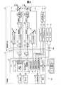
図2は、HMD100の構成を機能的に示すブロック図である。図2に示すように、制御部10は、記憶部120と、電源130と、無線通信部132と、操作部135と、CPU140と、インターフェイス180と、送信部51(Tx51)および送信部52(Tx52)と、を有している。操作部135は、使用者による操作を受け付け、決定キー11、表示切替キー13、トラックパッド14、輝度切替キー15、方向キー16、メニューキー17、電源スイッチ18、から構成されている。 FIG. 2 is a block diagram functionally showing the configuration of the
電源130は、HMD100の各部に電力を供給する。電源130としては、例えば二次電池を用いることができる。記憶部120は、種々のコンピュータープログラムを格納している。記憶部120は、ROMやRAM等によって構成されている。また、詳細については後述するが、記憶部120は、カメラ61の撮像画像に含まれる場合に検出される操作対象の画像データと制御を行なう判断の基となる判断対象の画像データとを記憶している。また、記憶部120は、操作対象等が検出された場合に画像表示部20に表示させる表示画像についても記憶している。 The
CPU140は、記憶部120に格納されているコンピュータープログラムを読み出して実行することにより、オペレーティングシステム150(OS150)、表示制御部190、音声処理部170、画像処理部160、画像判定部168、距離測定部166、画像設定部165、および、インターフェイス180として機能する。 The
表示制御部190は、右表示駆動部22および左表示駆動部24を制御する制御信号を生成する。具体的には、表示制御部190は、制御信号により、右LCD制御部211による右LCD241の駆動ON/OFF、右バックライト制御部201による右バックライト221の駆動ON/OFF、左LCD制御部212による左LCD242の駆動ON/OFF、左バックライト制御部202による左バックライト222の駆動ON/OFFなど、を個別に制御する。これにより、表示制御部190は、右表示駆動部22および左表示駆動部24のそれぞれによる画像光の生成および射出を制御する。例えば、表示制御部190は、右表示駆動部22および左表示駆動部24の両方に画像光を生成させたり、一方のみに画像光を生成させたり、両方共に画像光を生成させなかったりする。 The
表示制御部190は、右LCD制御部211と左LCD制御部212とに対する制御信号のそれぞれを、送信部51および52を介して送信する。また、表示制御部190は、右バックライト制御部201と左バックライト制御部202とに対する制御信号のそれぞれを送信する。 The
画像処理部160は、コンテンツに含まれる画像信号を取得する。画像処理部160は、取得した画像信号から、垂直同期信号VSyncや水平同期信号HSync等の同期信号を分離する。また、画像処理部160は、分離した垂直同期信号VSyncや水平同期信号HSyncの周期に応じて、PLL(Phase Locked Loop)回路等(図示しない)を利用してクロック信号PCLKを生成する。画像処理部160は、同期信号が分離されたアナログ画像信号を、A/D変換回路等(図示しない)を用いてディジタル画像信号に変換する。その後、画像処理部160は、変換後のディジタル画像信号を、対象画像の画像データ(RGBデータ)として、1フレームごとに記憶部120内のDRAMに格納する。なお、画像処理部160は、必要に応じて、画像データに対して、解像度変換処理、輝度、彩度の調整といった種々の色調補正処理、キーストーン補正処理等の画像処理を実行してもよい。 The
画像処理部160は、生成されたクロック信号PCLK、垂直同期信号VSync、水平同期信号HSync、記憶部120内のDRAMに格納された画像データ、のそれぞれを、送信部51、52を介して送信する。なお、送信部51を介して送信される画像データを「右眼用画像データ」とも呼び、送信部52を介して送信される画像データを「左眼用画像データ」とも呼ぶ。送信部51、52は、制御部10と画像表示部20との間におけるシリアル伝送のためのトランシーバーとして機能する。 The
音声処理部170は、コンテンツに含まれる音声信号を取得し、取得した音声信号を増幅して、連結部材46に接続された右イヤホン32内のスピーカー(図示しない)および左イヤホン34内のスピーカー(図示しない)に対して供給する。なお、例えば、Dolby(登録商標)システムを採用した場合、音声信号に対する処理がなされ、右イヤホン32および左イヤホン34のそれぞれからは、例えば周波数等が変えられた異なる音が出力される。音声処理部170は、マイク69が取得した外部の音声に対して各種処理を行なう。詳細については後述するが、音声処理部170は、各種処理として、取得した外部の音声が記憶部120に記憶された機器確認処理を行なう判断の基となる判断音声であるか否かを判定する。 The
画像判定部168は、パターンマッチングや統計的識別法によって、記憶部120に記憶された操作対象や判断対象の画像データと同じ画像が撮像画像に含まれているか否かを検出する。画像判定部168は、検出された判断対象の画像データと同じ画像である対象を、判断対象として検出する。なお、画像判定部168は、請求項における画像検出部に相当し、判断対象は、請求項における特定のオブジェクトに相当する。 The
距離測定部166は、TOFセンサー63が検出した赤外線の反射光について、TOF(Time of Flight)方式を用いることで、赤外線が発光されてから特定の対象を反射してTOFセンサー63に受光までの時間を算出することで、画像表示部20と特定の対象までの距離を測定する距離画像センサーである。距離測定部166は、画像判定部168によって検出された操作対象の画像データと同じ画像を表す特定の対象と画像表示部20との距離が予め設定された所定の距離以下であるか否かを判定する。なお、距離測定部166、TOFセンサー63、および、赤外線LED64は、請求項における距離特定部に相当する。 The
画像設定部165は、画像表示部20との距離が所定の距離以下であり、かつ、記憶部120に記憶された操作対象の画像データと同じ画像を表す特定の対象を、選択可能な操作対象として設定する。画像設定部165は、選択可能な操作対象を設定すると、記憶部120に記憶されている当該操作対象に対応付けられた画像を画像表示部20に表示させる。すなわち、画像判定部168によって、操作対象の画像データと同じ画像として検出されているが、画像表示部20との距離が所定の距離を超える特定の対象は、選択可能な操作対象としては設定されない。また、画像設定部165は、検出された判断対象に予め対応付けられた画像を画像表示部20に表示する。画像設定部165は、判断対象の位置の変化と操作対象の位置とに基づいて設定された制御指示を決定して実行する。なお、画像表示部20に表示される各種の画像についての詳細については、後述する。画像設定部165は、請求項における制御部に相当する。本実施形態における選択可能な操作対象は、請求項における選択可能な対象物に相当し、画像設定部165によって設定される制御指示は、請求項における対象物の制御に相当する。 The
インターフェイス180は、制御部10に対して、コンテンツの供給元となる種々の外部機器OAを接続するためのインターフェイスである。外部機器OAとしては、例えば、パーソナルコンピューター(PC)や携帯電話端末、ゲーム端末等、がある。インターフェイス180としては、例えば、USBインターフェイス、マイクロUSBインターフェイス、メモリーカード用インターフェイス等、を用いることができる。 The
画像表示部20は、右表示駆動部22と、左表示駆動部24と、右光学像表示部26としての右導光板261と、左光学像表示部28としての左導光板262と、カメラ61と、TOFセンサー63と、赤外線LED64と、マイク69と、を備えている。 The
右表示駆動部22は、受信部53(Rx53)と、光源として機能する右バックライト制御部201(右BL制御部201)および右バックライト221(右BL221)と、表示素子として機能する右LCD制御部211および右LCD241と、右投写光学系251と、を含んでいる。右バックライト制御部201と右バックライト221とは、光源として機能する。右LCD制御部211と右LCD241とは、表示素子として機能する。なお、右バックライト制御部201と、右LCD制御部211と、右バックライト221と、右LCD241と、を総称して「画像光生成部」とも呼ぶ。 The right
受信部53は、制御部10と画像表示部20との間におけるシリアル伝送のためのレシーバーとして機能する。右バックライト制御部201は、入力された制御信号に基づいて、右バックライト221を駆動する。右バックライト221は、例えば、LEDやエレクトロルミネセンス(EL)等の発光体である。右LCD制御部211は、受信部53を介して入力されたクロック信号PCLKと、垂直同期信号VSyncと、水平同期信号HSyncと、右眼用画像データと、に基づいて、右LCD241を駆動する。右LCD241は、複数の画素をマトリクス状に配置した透過型液晶パネルである。 The receiving
右投写光学系251は、右LCD241から射出された画像光を並行状態の光束にするコリメートレンズによって構成される。右光学像表示部26としての右導光板261は、右投写光学系251から出力された画像光を、所定の光路に沿って反射させつつ使用者の右眼REに導く。なお、右投写光学系251と右導光板261とを総称して「導光部」とも呼ぶ。 The right projection
左表示駆動部24は、右表示駆動部22と同様の構成を有している。左表示駆動部24は、受信部54(Rx54)と、光源として機能する左バックライト制御部202(左BL制御部202)および左バックライト222(左BL222)と、表示素子として機能する左LCD制御部212および左LCD242と、左投写光学系252と、を含んでいる。左バックライト制御部202と左バックライト222とは、光源として機能する。左LCD制御部212と左LCD242とは、表示素子として機能する。なお、左バックライト制御部202と、左LCD制御部212と、左バックライト222と、左LCD242と、を総称して「画像光生成部」とも呼ぶ。また、左投写光学系252は、左LCD242から射出された画像光を並行状態の光束にするコリメートレンズによって構成される。左光学像表示部28としての左導光板262は、左投写光学系252から出力された画像光を、所定の光路に沿って反射させつつ使用者の左眼LEに導く。なお、左投写光学系252と左導光板262とを総称して「導光部」とも呼ぶ。 The left
図3は、画像光生成部によって画像光が射出される様子を示す説明図である。右LCD241は、マトリクス状に配置された各画素位置の液晶を駆動することによって、右LCD241を透過する光の透過率を変化させることにより、右バックライト221から照射される照明光ILを、画像を表わす有効な画像光PLへと変調する。左側についても同様である。なお、図3に示すように、本実施形態ではバックライト方式を採用したが、フロントライト方式や、反射方式を用いて画像光を射出する構成としてもよい。 FIG. 3 is an explanatory diagram illustrating a state in which image light is emitted by the image light generation unit. The
A−2.機器確認処理:
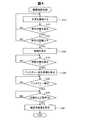
図4は、機器確認処理の流れを示す説明図である。機器確認処理では、制御部10が、選択可能な操作対象(例えば、制御機器のメーター)を設定した後に、判断対象(例えば、使用者の指)の所定の動き(以下、単に「ジェスチャー」とも呼ぶ)を検出すると、ジェスチャーに基づく制御指示である機器確認を実行する。A-2. Device confirmation processing:
FIG. 4 is an explanatory diagram showing the flow of the device confirmation process. In the device confirmation process, after the
初めに、カメラ61は、外景SCを撮像する(ステップS10)。なお、カメラ61は、連続的に外景SCを撮像している。言い換えれば、カメラ61は、動画として外景SCを撮像している。カメラ61は、撮像した撮像画像の画像データをCPU140の画像判定部168に送信する。次に、画像判定部168は、カメラ61によって撮像された撮像画像に対して、パターンマッチング等の画像認識処理を行なうことによって、撮像画像の中に記憶部120に記憶された操作対象の画像データと同じ画像が含まれているか否かを検出する(ステップS12)。撮像画像に操作対象と同じ画像データの画像が検出されなかった場合には(ステップS12:NO)、撮像画像に操作対象と同じ画像データの画像が検出されるまで、カメラ61によってステップS10の処理が繰り返される。ステップS12の処理において、撮像画像に操作対象と同じ画像データの画像が検出された場合には(ステップS12:YES)、CPU140の距離測定部166は、画像判定部168によって撮像画像に操作対象を表す画像の対象(以降、単に「仮対象」とも呼ぶ)が検出されると同時に、TOFセンサー63および赤外線LED64を用いたTOF方式によって、仮対象と画像表示部20との距離を測定する。距離測定部166は、画像判定部168によって検出された仮対象と画像表示部20との測定した距離が所定の距離以下であるか否かを判定する(ステップS14)。仮対象と画像表示部20との測定された距離が所定の距離を超えると判定された場合には(ステップS14:NO)、画像判定部168は、仮対象を選択可能な操作対象としては設定せずに、引き続き、カメラ61によってステップS10以降の処理が繰り返される。ステップS14の処理において、仮対象と画像表示部20との距離が所定の距離以下であると判定された場合には(ステップS14:YES)、画像設定部165は、画像判定部168によって検出された仮対象を選択可能な操作対象として設定し、操作対象に対応付けられた記憶部120に記憶された画像を画像表示部20に表示させる(ステップS16)。 First, the
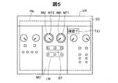
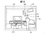
図5は、操作対象が設定された場合に使用者が視認する視野VRの一例を示す説明図である。図5に示すように、使用者は、設定された操作対象として、HMD100とは異なる装置である3台の制御機器MCを、透過された外景SCとして視認している。使用者に視認されている3台の内の中央の制御機器MCは、制御機器MCが制御している他の装置の電圧値を示すメーターMT1および温度を示すメーターMT2と、複数のボタンであるボタン群BTと、複数のランプを含むランプ群LMと、有している。ボタン群BTに含まれるそれぞれのボタンは、押下されることでオンとオフとを切り替えて他の装置を制御する。ランプ群LMのボタンのそれぞれは、ボタン群BTに含まれ、対応する上側に配置されたボタンがオンの時には点灯し、オフの時には消灯する。なお、メーターMT1およびメーターMT2は、請求項における選択可能な対象物に相当する。 FIG. 5 is an explanatory diagram illustrating an example of a visual field VR visually recognized by the user when an operation target is set. As shown in FIG. 5, the user visually recognizes three control devices MC, which are devices different from the
本実施形態において、記憶部120がメーターMT1およびメーターMT2の画像データを記憶しているため、画像判定部168は、メーターMT1およびメーターMT2を操作対象として検出する。画像判定部168がメーターMT1やメーターMT2を操作対象として設定すると、メーターMT1とメーターMT2とのそれぞれに対応付けられ、記憶部120に記憶された画像として、画像設定部165は、メーターMT1とメーターMT2とのそれぞれの位置を示す画像IM1と画像IM2とを画像表示部20の画像表示最大領域PNに表示させる。なお、画像表示最大領域PNは、画像光生成部が画像を表示できる最大の領域を示し、使用者には視認されない。また、画像設定部165は、記憶部120に記憶され、設定された操作対象としてのメーターMT1とメーターMT2との少なくとも一方に対応付けられた画像として、「確認?」というテキスト画像TX1を画像表示最大領域PNに表示される。テキスト画像TX1は、メーターMT1またはメーターMT2が示す数値の確認行為を使用者に促す画像である。 In the present embodiment, since the
画像判定部168によって操作対象としてのメーターMT1等が設定されて、画像設定部165によってテキスト画像TX1等の画像が画像表示最大領域PNに表示されると(図4のステップS16)、画像判定部168は、ジェスチャーを判断するための記憶部120に記憶された判断対象の画像データと同じ画像が撮像画像に含まれているか否かを検出する(ステップS18)。撮像画像に判断対象の画像が検出されなかった場合には(ステップS18:NO)、画像判定部168は、判断対象の検出を待機する(ステップS18)。撮像画像に判断対象の画像が検出された場合には(ステップS18:YES)、CPU140の画像設定部165は、記憶部120に記憶され、テキスト画像TX1が促す確認行為をするために使用者が行なうべきジェスチャーを指示するためのジェスチャー指示画像を、画像表示最大領域PNに表示させる(ステップS20)。 When the
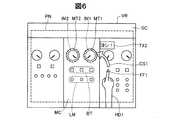
図6は、判断対象が検出された場合に使用者が視認する視野VRの一例を示す説明図である。図6には、判断対象としての検出された使用者の右手HD1の人差し指FF1が立てられた状態が示されている。図6に示すように、画像設定部165は、判断対象である右手HD1が検出された場合に、記憶部120に記憶されたメーターMT1およびメーターMT2の数値が定められた閾値未満であることを確認するために実行すべきジェスチャーを示すジェスチャー指示画像を画像表示最大領域PNに表示させる。なお、右手HD1の人差し指FF1は、請求項における特定のオブジェクトに相当する。ジェスチャー指示画像は、請求項における対象物対応虚像に相当する。 FIG. 6 is an explanatory diagram illustrating an example of a visual field VR visually recognized by the user when a determination target is detected. FIG. 6 shows a state in which the index finger FF1 of the detected user's right hand HD1 as the determination target is raised. As shown in FIG. 6, the
ジェスチャー指示画像は、右手HD1の人差し指FF1の先端からメーターMT1へと放物線の矢印画像CS1と、使用者が発生すべき判断音声である「ヨシ!」を示すテキスト画像TX2と、で構成される。本実施形態では、画像設定部165は、撮像画像において人差し指FF1がメーターMT1に重なる位置に移動した後に、マイク69および音声処理部170によって「ヨシ!」の判断音声が検出されると、確認行為の制御指示を実行する。なお、記憶部120に記憶された機器確認処理では、メーターMT1とメーターMT2との両方が検出された場合には、メーターMT1の機器確認を先に優先するように設定されている。使用者は、テキスト画像TX1,TX2および矢印画像CS1と重複する外景SCを透過して視認できる。確認行為の制御指示は、請求項における決定された対象物の制御に相当する。 The gesture instruction image includes a parabolic arrow image CS1 from the tip of the index finger FF1 of the right hand HD1 to the meter MT1, and a text image TX2 indicating “Yoshi!” Which is a judgment sound to be generated by the user. In the present embodiment, the
画像設定部165によって、ジェスチャー指示画像が画像表示最大領域PNに表示されると(図4のステップS20)、画像判定部168は、矢印画像CS1に沿った人差し指FF1のジェスチャーの検出を待機する(ステップS22)。画像判定部168は、カメラ61によって連続的に撮像される撮像画像の各フレームにおける人差し指FF1の画像に対して、パターンマッチング等の画像認識処理を行なうことによって、人差し指FF1のジェスチャーを検出する。矢印画像CS1に沿った人差し指FF1のジェスチャーが検出されない場合には(ステップS22:NO)、画像判定部168は、引き続き、矢印画像CS1に沿った人差し指FF1のジェスチャーの検出を待機する(ステップS22)。矢印画像CS1に沿った人差し指FF1のジェスチャーが検出された場合には(ステップS22:YES)、画像設定部165は、ジェスチャー後の人差し指FF1の位置が撮像画像においてメーターMT1に重なっている状態で、音声処理部170がマイク69を介してテキスト画像TX2に示す判断音声の「ヨシ!」の検出を待機する(ステップS24)。判断音声が検出されない、または、人差し指FF1の位置がメーターMT1と重なっていない場合には(ステップS24:NO)、画像設定部165は、引き続き、撮像画像において人差し指FF1の位置とメーターMT1とが重なっている状態での判断音声の検出を待機する(ステップS24)。撮像画像において、人差し指FF1の位置とメーターMT1とが重なっている状態で、判断音声の「ヨシ!」が検出された場合には(ステップS24:YES)、画像設定部165は、確認行為をするためのジェスチャーが行なわれたと判定し、確認行為が済んだ後に表示する確認済画像を画像表示最大領域PNに表示させ(ステップS26)、機器確認処理を終了する。なお、確認済画像は、請求項における特定確認画像に相当する。 When the
図7は、確認済画像が表示された場合に使用者が視認する視野VRの一例を示す説明図である。図7には、使用者による確認行為が検出されて確認済画像としての「MT1確認OK!」のテキスト画像TX3が表示されたときに使用者に視認される視野VRが示されている。撮像画像において、人差し指FF1の位置とメーターMT1とが重なっている場合に、画像設定部165は、メーターMT1の位置を示す画像IM1に加えて、メーターMT1の数値が確認済みであることを示すために、メーターMT1を囲っている実線の円の画像IM3を画像表示最大領域PNに表示させる。使用者は、画像表示最大領域PNに表示されたテキスト画像TX3および画像IM3を視認することで、ジェスチャーが正常に処理されて、機器確認の制御指示が実行されたことを確認できる。 FIG. 7 is an explanatory diagram illustrating an example of a visual field VR visually recognized by the user when a confirmed image is displayed. FIG. 7 shows a visual field VR visually recognized by the user when a confirmation action by the user is detected and a text image TX3 of “MT1 confirmation OK!” As a confirmed image is displayed. In the captured image, when the position of the index finger FF1 and the meter MT1 overlap, the
以上説明したように、本実施形態におけるHMD100では、画像判定部168が撮像画像の中に含まれる操作対象と判断対象とを検出し、画像設定部165は、検出された操作対象に対応付けられた画像IM1,IM2およびテキスト画像TX1を画像表示最大領域PNに表示させ、検出された判断対象のジェスチャーに対応する機器確認の制御指示を決定して実行する。そのため、本実施形態のHMD100では、使用者は、操作する対象の操作対象と自身が行なうジェスチャーに対応付けられた制御とを視線方向を変えないで同時に視認でき、操作対象の制御を直感的に行なうことができ、使用者の利便性が向上する。 As described above, in the
また、本実施形態におけるHMD100では、画像設定部165は、判断対象としての右手HD1が検出されると、メーターMT1およびメーターMT2と右手HD1の人差し指FF1との組み合わせに対応付けられた画像として、人差し指FF1の変化を示した矢印画像CS1を画像表示最大領域PNに表示させる。そのため、本実施形態のHMD100では、使用者は、制御指示を実行するために必要なジェスチャーを視覚情報として認識でき、使用者にとってのHMD100の使い勝手が向上する。 Further, in the
また、本実施形態におけるHMD100では、画像設定部165は、判断対象である人差し指FF1の位置と操作対象であるメーターMT1とが重なっている状態で、音声処理部170によって判断音声が検出された場合に、確認済画像であるテキスト画像TX3を画像表示最大領域PNに表示させる。そのため、本実施形態のHMD100では、ジェスチャーが行われた後に判断対象が重なっている操作対象に対応する制御指示が実行されるため、使用者は、意図した制御指示に対応するジェスチャーを行ないやすい。また、ジェスチャーと音声との組み合わせによって制御指示が実行されるため、ジェスチャーのみによって実行される制御指示よりも、使用者は、より多くの制御指示を直感的に行なうことができる。 Further, in the
また、本実施形態におけるHMD100では、距離測定部166によって測定された画像表示部20と仮対象との距離が所定の距離以下である場合に、画像設定部165は、検出された仮対象を選択可能な操作対象として設定する。そのため、本実施形態のHMD100では、撮像画像に複数の仮対象が検出された場合に、使用者から近いものを選択可能な操作対象として設定するので、使用者に選択される可能性の高いものを使用者に視認させるため、使用者の利便性が向上する。 In the
B.第2実施形態:
第2実施形態では、第1実施形態と異なり、HMD100aと制御装置300とを備える制御システム500において、HMD100aと制御装置300との間で制御指示の信号の送受信が行なわれる。これにより、制御装置300からの操作対象を特定する情報をHMD100aが受信した後に、HMD100aで入力された制御指示に基づいて制御装置300の制御が行なわれる。B. Second embodiment:
In the second embodiment, unlike the first embodiment, in a
図8は、第2実施形態における制御システム500の構成を機能的に示すブロック図である。制御システム500は、HMD100aと制御装置300とを備えている。なお、図8では、HMD100aと制御装置300とをそれぞれ1つずつしか図示していないが、制御システム500は、複数のHMD100aや制御装置300を備えていてもよいし、HMD100aや制御装置300とは異なる機器(例えば、サーバー)を介して情報の送受信が行なわれてもよい。第2実施形態におけるHMD100aは、第1実施形態のHMD100の構成に加えて、制御部10に無線通信部132を備えている。図8では、HMD100aが第1実施形態(図2)のHMD100と比較して、無線通信部132以外の構成が同じであるため、HMD100aの構成については、一部の図示を省略している。 FIG. 8 is a block diagram functionally showing the configuration of the
HMD100aの無線通信部132は、無線LANやブルートゥース(登録商標)といった所定の無線通信方式に則って他の機器との間で無線通信を行なう。無線通信部132は、使用者のジェスチャーによって決定された制御指示の情報を制御装置300へと送信する。また、無線通信部132は、操作対象、判断対象、判断音声、および、ジェスチャー等を特定する情報を制御装置300から受信する。なお、第2実施形態における無線通信部132は、請求項における第2の通信部に相当する。 The
制御装置300は、無線通信部330と、記憶部320と、CPU310と、を備えている。無線通信部330は、無線LANやブルートゥースといった所定の無線通信方式に則って、HMD100との間で無線通信を行なう。なお、第2実施形態における無線通信部330は、請求項における第1の通信部に相当する。記憶部320は、例えば、ROM、RAM、DRAM、ハードディスク等によって構成されている。記憶部320は、制御装置300を制御するための制御指示に対応付けられた制御内容を記憶している。また、記憶部320は、カメラ61の撮像画像に含まれる場合に検出される操作対象の画像データと制御を行なう判断の基となる判断対象の画像データとを記憶している。なお、第2実施形態における記憶部320は、請求項における対象物特定部に相当する。 The
CPU310は、記憶部320に格納されたコンピュータープログラムを読み出して実行することにより、情報処理部312、制御処理部314、として機能する。情報処理部312は、無線通信部330を介して、HMD100の無線通信部132との間で送受信される制御指示や操作対象を特定する情報を処理する。制御処理部314は、情報処理部312によって処理された制御指示の情報に基づいて、当該制御指示に対応して制御装置300を制御する。なお、第2実施形態における制御装置300は、請求項における制御実行部に相当する。 The
図9は、制御処理の流れを示す説明図である。制御処理におけるステップS30からステップS36までの処理は、第1実施形態の機器確認処理(図4)における画像表示部20と操作対象との距離を特定する処理を除いたステップS10からステップS18までの処理が同じである。そのため、第2実施形態では、制御処理のステップS30からステップS36までの処理については、簡単に説明する。 FIG. 9 is an explanatory diagram showing the flow of control processing. The processing from step S30 to step S36 in the control processing is from step S10 to step S18 excluding the processing for specifying the distance between the
制御処理では、カメラ61によって外景SCが撮像され(ステップS30)、撮像画像に操作対象が検出されると(ステップS32:YES)、画像設定部165は、操作対象に対応付けられた画像を画像表示最大領域PNに表示させる。 In the control process, when the outside scene SC is imaged by the camera 61 (step S30) and an operation target is detected in the captured image (step S32: YES), the
図10は、操作対象が検出された場合に使用者が視認する視野VRの一例を示す説明図である。図10には、リビングにいる使用者が視認する外景SCと画像表示最大領域PNに表示された画像IM4および画像IM5とが示されている。図10に示すように、使用者は、画像判定部168によって設定された操作対象であるテレビのリモコンRC1および部屋の照明のスイッチであるスイッチSWと、記憶部320に記憶され、リモコンRC1に対応付けられた画像IM4およびスイッチSWに対応付けられた画像IM5と、を視認している。なお、リモコンRC1およびスイッチSWは、請求項における対象物に相当する。 FIG. 10 is an explanatory diagram illustrating an example of a visual field VR visually recognized by the user when an operation target is detected. FIG. 10 shows the outside scene SC visually recognized by the user in the living room and the images IM4 and IM5 displayed in the maximum image display area PN. As shown in FIG. 10, the user stores the television remote controller RC1 that is the operation target set by the
画像IM4およびIM5が表示された状態で(図9のステップS34)、画像判定部168によって判断対象が検出されると(ステップS36:YES)、画像設定部165は、使用者のジェスチャーを検出できる状態を示すジェスチャー検出モードの画像を画像表示最大領域PNに表示させる(ステップS38)。 When the
図11は、ジェスチャー検出モードの場合に使用者が視認する視野VRの一例を示す説明図である。図11に示すように、画像判定部168によって判断対象としての右手HD1が検出され、画像設定部165によって、リモコンRC1に対応付けられた画像IM6が表示され、スイッチSWに対応付けられた矢印画像CS2と画像IM7とが表示される。画像IM6は、右手HD1の人差し指FF1の位置が重なると制御する内容を示す複数のアイコンを含む画像である。例えば、表示されたアイコンの内の「ON/OFF」のアイコンが指FF1の位置の変化によって選択されると、制御処理部314は、テレビTV1の電源のオンとオフとを切り替える制御を実行する。また、図11に示す矢印画像CS2は、スイッチSWを選択する制御を実行するために使用者が行なうべきジェスチャーを示す画像である。画像IM7は、矢印画像CS2に沿った人差し指FF1のジェスチャーが行なわれると、実行される制御内容を示す画像である。すなわち、画像IM7は、使用者の人差し指FF1が矢印画像CS2に沿ってスイッチSWを囲むように動くと、スイッチSWが選択されることを示している。 FIG. 11 is an explanatory diagram illustrating an example of the visual field VR visually recognized by the user in the gesture detection mode. As shown in FIG. 11, the
画像設定部165によってジェスチャー検出モードの画像が画像表示最大領域PNに表示されると(図9のステップS38)、画像判定部168は、リモコンRC1またはスイッチSWの制御を実行するための右手HD1のジェスチャーの検出を待機する(ステップS40)。右手HD1のジェスチャーが検出されなかった場合には(ステップS40:NO)、画像判定部168は、引き続き、右手HD1のジェスチャーの検出を待機する(ステップS40)。右手HD1のジェスチャーが検出された場合には(ステップS40:YES)、画像設定部165は、検出されたジェスチャーである検出ジェスチャーに対応する制御を実行する(ステップS42)。画像設定部165は、検出ジェスチャーに対応して実行された制御の次に設定されている別の制御を実行するために対応するジェスチャーである設定ジェスチャーがあるか否かを判定する(ステップS44)。設定ジェスチャーがあると判定された場合には(ステップS44:YES)、画像設定部165は、設定ジェスチャーに対応したジェスチャー検出モードの画像を画像表示最大領域PNに表示させる(ステップS38)。 When the image in the gesture detection mode is displayed in the maximum image display area PN by the image setting unit 165 (step S38 in FIG. 9), the
図12は、設定ジェスチャーに対応するジェスチャー検出モードの画像が表示された場合に使用者が視認する視野VRの一例を示す説明図である。図12には、検出ジェスチャーとして矢印画像CS2(図11)に沿った人差し指FF1の動きが検出された後の設定ジェスチャーに対応したジェスチャー指示画像である画像IM8が示されている。画像IM8は、人差し指FF1が上方向に動かされた場合にはスイッチSWをオンにし、人差し指FF1が下方向に動かされた場合にはスイッチSWをオフにする制御を示す画像である。 FIG. 12 is an explanatory diagram illustrating an example of the visual field VR visually recognized by the user when an image in the gesture detection mode corresponding to the setting gesture is displayed. FIG. 12 shows an image IM8 that is a gesture instruction image corresponding to the set gesture after the movement of the index finger FF1 along the arrow image CS2 (FIG. 11) is detected as a detected gesture. The image IM8 is an image showing control for turning on the switch SW when the index finger FF1 is moved upward, and turning off the switch SW when the index finger FF1 is moved downward.
画像設定部165によってジェスチャー検出モードの画像が画像表示最大領域PNに表示され(図9のステップS38)、スイッチSWをオンまたはオフにするジェスチャーが検出されると(ステップS40:YES)、画像設定部165は、検出ジェスチャーに対応する制御を実行する(ステップS42)。実行された制御の次に実行される制御に対応する設定ジェスチャーがある場合には(ステップS44:YES)、ステップS38以降の処理が行なわれる。ステップS44の処理において、実行された制御の次に実行される制御に対応する設定ジェスチャーがない場合には(ステップS44:NO)、画像設定部165は、検出ジェスチャーに対応する制御が実行されたことを示す制御後画像を画像表示最大領域PNに表示させる(ステップS46)。 When the
図13は、制御後画像が表示された場合に使用者が視認する視野VRの一例を示す説明図である。図13には、検出ジェスチャーとしてのスイッチSWをオフに設定ジェスチャーが検出された後に、制御後画像であるテキスト画像TX4が表示された状態が示されている。図13に示すように、制御処理部314によってスイッチSWがオフに設定されると、その旨を使用者に伝えるための「オフにしました」のテキスト画像TX4が画像設定部165によって画像表示最大領域PNに表示される。 FIG. 13 is an explanatory diagram illustrating an example of a visual field VR visually recognized by the user when a post-control image is displayed. FIG. 13 shows a state in which a text image TX4, which is a post-control image, is displayed after a switch gesture as a detection gesture is turned off and a gesture is detected. As shown in FIG. 13, when the switch SW is turned off by the
制御後画像のテキスト画像TX4が画像表示最大領域PNに表示されると(図9のステップS46)、画像設定部165は、所定の時間、テキスト画像TX4を画像表示最大領域PNに表示する。テキスト画像TX4が画像表示最大領域PNに表示されている間に、操作部135は、撮像画像において検出された操作対象等を用いた制御処理を終了する所定の操作の検出を待機する(ステップS48)。テキスト画像TX4が画像表示最大領域PNに表示されている間に、操作部135が制御処理を終了する所定の操作を検出しなかった場合には(ステップS48:NO)、画像設定部165がテキスト画像TX4を非表示にした後、ステップS32以降の処理が行なわれる。ステップS48の処理において、操作部135が制御処理を終了する所定の操作を検出した場合には(ステップS48:YES)、制御部10は、制御処理を終了する。なお、第2実施形態では、操作部135が所定の操作を検出することで、制御処理の途中であっても、制御部10は、制御処理を終了できる。 When the text image TX4 of the post-control image is displayed in the image display maximum area PN (step S46 in FIG. 9), the
以上説明したように、第2実施形態におけるHMD100aでは、図12に示すように、画像設定部165は、右手HD1の人差し指FF1が上下方向に沿って動いた方向に対応して実行されるスイッチSWのオンとオフとの制御を示す画像IM8を画像表示最大領域PNに表示させる。そのため、第2実施形態のHMD100aでは、使用者が自身のジェスチャーに対応して次に実行される制御の内容を視覚情報として認識できるので、使用者にとっての使い勝手が向上する。 As described above, in the HMD 100a according to the second embodiment, as illustrated in FIG. 12, the
C.第3実施形態:
第3実施形態では、第1実施形態および第2実施形態と比較して、操作対象の位置情報が光情報や無線通信などによって取得されることと、判断対象の加速度を検出することで判断対象の位置の変化を特定することと、が主に異なる。C. Third embodiment:
In the third embodiment, compared with the first embodiment and the second embodiment, the position information of the operation target is acquired by optical information or wireless communication, and the determination target is detected by detecting the acceleration of the determination target. It is mainly different from specifying the change of the position of.
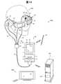
図14は、第3実施形態における制御システム500bの構成を示す概略図である。制御システム500bは、HMD100bと、サーバー400と、制御装置300bと、を備えている。HMD100bは、画像表示部20bと、制御部10bと、判断対象としての外部センサー70と、を備えている。外部センサー70は、外部センサー70の動きを検出するための加速度センサーを内蔵している。外部センサー70は、検出した加速度を、ブルートゥースなどの通信手段を用いて制御部10bに送信する。制御部10bは、送信された外部センサー70の加速度に基づいて、外部センサー70の位置の変化を算出する。制御部10bは、算出した外部センサー70の位置の変化に基づいて、制御装置300bを制御する。画像表示部20bは、第1実施形態および第2実施形態におけるTOFセンサー63と赤外線LED64とを有していない。なお、本実施形態では、図1に示すように、制御装置300bをテレビとして説明しているが、他の実施形態では、制御装置300bとして、テレビ以外の照明装置などであってもよい。 FIG. 14 is a schematic diagram illustrating a configuration of a
サーバー400は、検出されたジェスチャーによって制御指示される制御機器と、制御機器に制御指示を与えるための操作対象と、の制御装置300bの情報を記憶する記憶部420を有する。なお、第3実施形態におけるジェスチャーとは、外部センサー70の位置の変化を含む。サーバー400は、HMD100bから送信される信号に対応させて、記憶部420に記憶された情報の少なくとも一部を、HMD100bへと送信する。HMD100bの制御部10bの無線通信部132bは、サーバー400から送信された情報を受信する。 The
図15は、サーバー400の記憶部420に記憶された制御装置の情報の一部を示す概略図である。記憶部420は、複数の制御装置300bの情報を記憶している。例えば、図15に示すように、1つの制御装置300bとしてのテレビは、放映される番組を表示する制御機器と、制御機器を操作するコントローラーと、のそれぞれについて、三次元モデルと位置座標とに関連付けられている。また、制御装置300bのテレビは、表示情報に関連付けられている。図15に示す三次元モデルは、制御機器とコントローラーとのそれぞれについて記憶された立体的な画像データである。位置座標は、HMD100bがサーバー400からの情報を受信したときに、HMD100bを基準とした場合に制御機器とコントローラーとのそれぞれが位置する場所を示す。表示画像は、コントローラーが検出された場合に、画像表示部20bに表示される画像の内容の一例である。 FIG. 15 is a schematic diagram illustrating a part of the control device information stored in the
第3実施形態では、制御装置300bの記憶部320bは、複数の手順によって実行されるシーケンス制御におけるそれぞれの手順を記憶している。例えば、制御装置300bがテレビであり、将来の時間を指定して放映される番組を録画する(単に、「録画予約を行なう」ともいう)場合には、日時や放映される番組のチャンネルなどの複数の手順が正しく入力されると、録画予約が行なわれる。 In 3rd Embodiment, the memory | storage part 320b of the
図16は、第3実施形態におけるHMD100bの構成を機能的に示すブロック図である。第3実施形態の記憶部120bは、第1実施形態および第2実施形態の記憶部120と異なり、HMD100bの使用者を識別するための個人情報を記憶している。図16に示すように、第3実施形態の制御部10bのCPU140bは、第1実施形態および第2実施形態における距離測定部166を有しておらず、位置特定部163と識別部161とを有している。識別部161は、HMD100bの電源が入ると、HMD100bの使用者を識別するための画像を画像表示最大領域PNに表示させる。その後、操作部135が受け付けた操作に基づいて、識別部161は、HMD100bの使用者を特定する。使用者の識別方法として、例えば、以下のステップが行なわれる場合がある。初めに、識別部161が、予め登録されたHMD100bの過去の使用者を選択させる画像を画像表示最大領域PNに表示させる。その後、操作部135が受け付けた操作によって選択された使用者に対応するように、識別部161は、記憶部320bに記憶されたパスワードの入力を要求する画像を画像表示最大領域PNに表示させ、要求したパスワードが入力されると、HMD100bの使用者を特定する。 FIG. 16 is a block diagram functionally showing the configuration of the
位置特定部163は、無線通信部132bを介して、サーバー400の記憶部420から取得した制御機器の位置情報と操作対象であるコントローラーの位置情報とに基づいて、画像表示部20bと制御機器と操作対象との位置関係を特定する。なお、画像表示部20bの位置は、電波の強さや複数の基地局などによって送受信される電波の時差などに基づいて特定される。また、位置特定部163は、外部センサー70が検出した加速度に基づいて、外部センサー70の位置の変化を特定する。なお、外部センサー70は、請求項における特定のオブジェクトに相当する。 The
図17は、第3実施形態における制御処理の流れを示す説明図である。第3実施形態の制御処理は、検出された外部センサー70の変化に基づいて、位置が特定された制御機器の制御指示が実行される処理である。 FIG. 17 is an explanatory diagram showing a flow of control processing in the third embodiment. The control process of the third embodiment is a process in which a control instruction for the control device whose position is specified is executed based on the detected change of the
第3実施形態の制御処理では、初めに、識別部161は、HMD100bの使用者を識別する(ステップS50)。第3実施形態では、識別された使用者ごとに、検出される制御装置300bの種類が異なる。具体的には、ある使用者では、特定の制御装置を制御指示が可能な対象として検出されるが、異なる使用者では、特定の制御装置を制御指示が不可能な対象として判定し、特定の制御装置が検出されない。 In the control process of the third embodiment, first, the
使用者が識別されると、位置特定部163は、無線通信部132bを介して、サーバー400から、画像表示部20bを装着している使用者から所定の範囲内にある制御装置の位置を特定する(ステップS51)。次に、カメラ61は、外景を撮像する(ステップS52)。次に、位置特定部163は、使用者から所定の範囲内に位置が特定された制御装置300bが検出されたか否かを判定する(ステップS54)。位置特定部163は、制御装置300bを検出しなかった場合には(ステップS54:NO)、引き続き、使用者から所定の範囲内にある制御装置300bの位置の特定を待機する(ステップS51)。なお、第3実施形態において検出有無の対象となる制御装置300bとは、制御機器とコントローラーとの少なくとも一方であればよい。 When the user is identified, the
ステップS54の処理において、制御装置300bが検出された場合には(ステップS54:YES)、画像設定部165は、制御装置300bの位置を示す画像を画像表示最大領域PNに表示させる(ステップS56)。なお、第3実施形態では、位置特定部163は、制御装置300bの位置として特定した場所の撮像範囲に対して、サーバー400の記憶部420に記憶された制御装置300bの三次元モデルを基準としてパターンマッチング等を用いることで、使用者に対する制御装置300bの位置の精度を向上させている。なお、他の実施形態では、位置特定部163は、画像認識によって制御装置300bの位置を特定する必要はない。 When the
図18は、制御装置300bが検出された場合に使用者が視認する視野VRの一例を示す説明図である。図18に示すように、検出された制御装置300bとしての3つの組み合わせを表す対応マーカーMK1,MK2,MK3と、鳥瞰図VIと、が画像表示最大領域PNに表示されている。図18に示す例において、検出された3つの制御装置300bは、下記の通りである。
(1)制御機器としてのテレビTV1およびコントローラーとしてのリモコンRC1
(2)制御機器としての照明LTおよびコントローラーとしてのスイッチSW
(3)制御機器としてのエアコンACおよびコントローラーとしてのリモコンRC2
3つの制御装置における制御機器とコントローラーとのそれぞれは、同じ形で同じ色の画像である対応マーカーMK1,MK2,MK3で関連付けて示されている。例えば、制御機器MCとしてのテレビTV1と、コントローラー10としてのリモコンRC1との近くには、対応マーカーMK1が表示画像として画像表示最大領域PNに表示される。なお、第3実施形態における同じ形の対応マーカーとは、表示された対応マーカーのサイズが異なっていても、同じ形の対応マーカーという。FIG. 18 is an explanatory diagram illustrating an example of a visual field VR visually recognized by the user when the
(1) Television TV1 as a control device and remote controller RC1 as a controller
(2) Lighting LT as a control device and switch SW as a controller
(3) Air conditioner AC as control equipment and remote controller RC2 as controller
Each of the control devices and the controllers in the three control devices is shown in association with corresponding markers MK1, MK2, and MK3 that are images of the same shape and the same color. For example, the corresponding marker MK1 is displayed in the maximum image display area PN as a display image near the television TV1 as the control device MC and the remote controller RC1 as the
鳥瞰図VIは、画像表示部20bを装着している使用者を中心として、使用者の上から見たときの使用者と、カメラ61の撮像範囲eyと、撮像範囲には含まれない検出されたリモコンRC2と、の位置関係の概略を示す縮小図である。位置特定部163によって位置が特定された制御装置300bの一部がカメラ61の撮像範囲に含まれていない場合に、画像設定部165は、使用者と撮像範囲に含まれていない制御装置300bの一部との位置関係を示す鳥瞰図VIを画像表示最大領域PNに表示させる。鳥瞰図VIに示すように、使用者の右方向にエアコンACのリモコンRC2が存在している。 The bird's-eye view VI is detected by the user wearing the
画像表示最大領域PNに制御装置300bの位置を示す画像が表示されると(図17のステップS56)、位置特定部163は、判断対象としての外部センサー70の位置の変化を検出の有無を判定する(ステップS58)。位置特定部163は、外部センサー70の位置の変化を検出しない場合には(ステップS58:NO)、引き続き、判断対象としての外部センサー70の位置の変化の検出を待機する(ステップS58)。 When an image indicating the position of the
ステップS58の処理において、判断対象としての外部センサー70の位置の変化が検出された場合には(ステップS58:YES)、画像設定部165は、検出された外部センサー70の位置の変化に対応した制御装置300bの制御指示を実行する(ステップS60)。外部センサー70の位置の変化に対応した制御指示としては、制御装置300bのそれぞれに対して異なる制御指示が設定されている場合がある。例えば、テレビTV1のリモコンRC1を選択する場合には、外部センサー70から、対応付けられた対応マーカーの丸の形状を描く位置の変化が検出されると、画像設定部165は、画像IM4に対応したテレビTV1のメニュー画像を画像表示最大領域PNに表示させる。なお、他の実施形態では、カメラ61の撮像画像の中に外部センサー70が含まれる場合には、画像設定部165は、検出された外部センサー70の加速度と撮像された外部センサー70の変化とに基づいて、制御装置300bに対する制御指示を実行してもよい。 When a change in the position of the
検出された操作対象としての外部センサー70の位置の変化に応じた制御指示が実行されると(図17のステップS60)、画像設定部165は、制御後の画像を画像表示最大領域PNに表示させる(ステップS62)。第3実施形態では、制御装置300bの記憶部320bには、複数の手順によって実行されるシーケンス制御の手順が記憶されているため、制御後の画像が画像表示最大領域PNに表示された後に、画像設定部165は、無線通信部132bを介して、シーケンス制御の次の手順として設定された対応シーケンスが制御装置300bの記憶部320bにあるか否かを判定する(ステップS64)。画像設定部165は、対応シーケンスがあると判定した場合には(ステップS64:YES)、対応シーケンスに対応付けられた画像を画像表示最大領域PNに表示させる(ステップS66)。 When a control instruction according to the detected change in the position of the
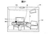
図19は、対応シーケンスに対応付けられた画像が画像表示最大領域PNに表示された場合に使用者が視認する視野VRを示す説明図である。図19には、図18に示すリモコンRC1に対応付けられた画像IM4のメニューが選択され、その後、予約録画を行なう際のチャンネルを設定するための画面を表す画像IM9が画像表示最大領域PNに表示された状態が示されている。リモコンRC1が操作されて予約録画が行なわれる際には、録画するチャンネルの設定、予約録画が行なわれる日時、一週間ごとの定期的な予約録画を行なうか否かの順序に沿ったシーケンス制御が行なわれる。 FIG. 19 is an explanatory diagram showing the visual field VR visually recognized by the user when an image associated with the corresponding sequence is displayed in the image display maximum area PN. In FIG. 19, the menu of the image IM4 associated with the remote controller RC1 shown in FIG. 18 is selected, and then an image IM9 representing a screen for setting a channel for performing scheduled recording is displayed in the image display maximum area PN. The displayed state is shown. When reservation recording is performed by operating the remote controller RC1, sequence control is performed in accordance with the order of setting the recording channel, the date and time when reservation recording is performed, and whether or not to perform periodic reservation recording every week. Done.
画像IM9が画像表示最大領域PNに表示されると、図17のステップS58の処理として、外部センサー70が数字を描く動作を検出すると(ステップS58:YES)、画像設定部165は、検出された動作に対応した数字をチャンネルとして設定し(ステップS60)、画像IM9の「**」の部分に設定された数字を表示させる(ステップS62)。例えば、使用者が何もない空間で「8」の数字を描くように外部センサー70を動かすと、録画するチャンネルとして「8」チャンネルが設定される。また、外部センサー70が画像IM9に示してある矢印の方向の左に振られる変化を検出すると、画像設定部165は、検出に応じた制御として、シーケンス制御における録画するチャンネルの設定の1つ前の画像を画像表示最大領域PNに表示させる。また、録画するチャンネルの数字が入力された状態、外部センサー70が画像IM9に示してある矢印の方向の右に振られる変化を検出すると、画像設定部165は、録画するチャンネルを設定して、シーケンス制御における録画するチャンネルの設定の次の画像を画像表示最大領域PNに表示させる。その後、同じようにステップS64以降の処理が行なわれる。 When the image IM9 is displayed in the image display maximum area PN, when the
以上説明したように、第3実施形態のHMD100bでは、制御部10bの無線通信部132bは、サーバー400の記憶部420に記憶された制御装置300bの位置情報を受信する。また、そのため、第3実施形態のHMD100bでは、使用者が視認できない範囲の制御装置300bの位置も認識でき、使用者の使い勝手が向上する。 As described above, in the
また、第3実施形態のHMD100bでは、画像設定部165は、図19に示すように、画像表示部20bを装着した使用者と検出されたリモコンRC2との位置関係を示す鳥瞰図VIを画像表示最大領域PNに表示させる。そのため、第3実施形態のHMD100bでは、使用者が視認できない範囲の制御装置300bの位置と使用者との位置関係を画像として視認でき、使用者の使い勝手がより向上する。 In the
また、第3実施形態のHMD100bでは、外部センサー70は、外部センサー70の位置の変化としての加速度を検出する。画像設定部165は、検出された外部センサー70の位置の変化に基づいて、制御装置300bへの制御指示を実行する。そのため、第3実施形態のHMD100bでは、使用者が制御装置300bへの制御指示を実行する場合に、特定の場所を操作したり、操作として対応付けられ動作を撮像される範囲で行なう必要がなく、使用者の利便性が向上する。 In the
また、第3実施形態のHMD100bでは、図18に示すように、画像設定部165は、検出された制御機器の位置と検出された制御機器のコントローラーの位置とを、同じ形で同じ色の画像である対応マーカーによって対応付けて画像表示最大領域PNに表示させる。そのため、第3実施形態のHMD100bでは、検出された制御機器と検出された制御機器のコントローラーとの対応関係を視認させることができ、使用者の使い勝手が向上する。 In the
また、第3実施形態のHMD100bでは、識別部161がHMD100bの使用者を特定し、画像設定部165は、特定された使用者の制御指示が可能な制御装置についての画像を画像表示最大領域PNに表示させる。そのため、第3実施形態のHMD100bでは、特定された使用者ごとに異なる画像が画像表示最大領域PNに表示されるため、使用者のニーズにあった情報を提供できる。 Further, in the
D.変形例:
なお、この発明は上記実施形態に限られるものではなく、その要旨を逸脱しない範囲において種々の態様において実施することが可能であり、例えば、次のような変形も可能である。D. Variations:
In addition, this invention is not limited to the said embodiment, It can implement in a various aspect in the range which does not deviate from the summary, For example, the following deformation | transformation is also possible.
D1.変形例1:
上記実施形態では、画像設定部165は、設定された操作対象および検出された判断対象に対応する画像やジェスチャー指示画像を画像表示最大領域PNに表示したが、必ずしもこれらの画像を表示しなくてもよい。例えば、画像設定部165は、設定された操作対象に対応する画像を表示し、判断対象に対応する画像やジェスチャー指示画像を表示せずに、検出されたジェスチャーに対応する制御を実行してもよい。D1. Modification 1:
In the above-described embodiment, the
上記実施形態では、距離測定部166は、赤外線LED64とTOFセンサー63とによって、画像表示部20と仮対象との距離を測定したが、必ずしも当該距離を測定する必要もなく、また、他の方法によって距離を測定してもよい。例えば、画像設定部165は、画像表示部20と操作対象との距離に関係なく、画像判定部168によって検出された仮対象の全てを選択可能な操作対象として設定してもよい。また、距離測定部166は、ステレオカメラによって撮像された操作対象の画像を比較することで、画像表示部20と操作対象との距離を測定してもよい。 In the above embodiment, the
上記実施形態では、画像判定部168は、判断対象として右手HD1の人差し指FF1を検出したが、検出する判断対象については、種々変形可能である。例えば、判断対象は、制御部10であってもよいし、ボールペンや制御部10のトラックパッド14を操作するためのタッチペンであってもよい。また、判断対象は、人差し指FF1の延長線上を指示するための棒状の器具であってもよいし、レーザーポインターにおける特定の光の形状であってもよいし、発光部を有する特定の形状の器具(例えば、懐中電灯)などであってもよい。発光状態のペンライトが判断対象として検出され、発光状態ではないペンライトが判断対象として検出されないように、発光の有無によって判断対象の検出の有無が判定されてもよい。発光の有無によって判断対象として検出されるか否かが決定される場合、判断対象としてより精度の高い検出が行なわれる。判断対象は、操作部135が操作されることにより、使用者に任意に設定されてもよい。また、判断対象は、使用者の腕に装着される腕時計型のウェアラブルデバイスや使用者の指に装着されるリング型ウェアラブルデバイスなどであってもよい。 In the above embodiment, the
また、検出される判断対象は1つに限られず、2つ以上であってもよい。例えば、判断対象として、2つの指が検出されて、2つの指の距離や形状がジェスチャーの代わりに認識されてもよい。例えば、判断対象として検出された2つの指の動きによって、表示画像の拡大または縮小の制御を実行するピンチインやピンチアウトに相当するジェスチャーが検出されてもよい。同じような2つの指による操作として、ボリュームのつまみを判断対象として2つの指で摘んで時計回りなどに回すことで、出力されるボリュームが変化してもよい。また、例えば、キーボードを操作する場合に、シフトキーを押しながら特定の文字を選択すると大文字のアルファベットが入力されるような操作の代替手段として、検出された2つの指の位置関係において、一方の指の位置に対するもう一方の指の相対的な動きを検出することで、種々の入力が検出されてもよい。 Further, the number of determination targets to be detected is not limited to one, and may be two or more. For example, two fingers may be detected as a determination target, and the distance and shape of the two fingers may be recognized instead of the gesture. For example, a gesture corresponding to a pinch-in or a pinch-out for controlling enlargement or reduction of the display image may be detected based on the movement of two fingers detected as the determination target. As an operation with two similar fingers, the output volume may be changed by picking the knob of the volume with two fingers as a determination target and turning it clockwise. In addition, for example, when operating a keyboard, as an alternative to an operation in which a capital letter is input when a specific character is selected while pressing the shift key, one finger in the positional relationship between two detected fingers is used. Various inputs may be detected by detecting the relative movement of the other finger with respect to the position of.
上記第1実施形態では、画像設定部165は、ジェスチャーとジェスチャー後に検出された判断音声との組み合わせによってメーターMT1の確認行為を判定したが、必ずしも判断音声が検出される必要はなく、ジェスチャーのみによってメーターMT1の確認行為を判定してもよい。また、画像設定部165は、ジェスチャー後の判断音声を検出することで、メーターMT1の確認行為を判定したが、判断音声を検出するタイミングはジェスチャー後に限られず、ジェスチャー前であってもよいし、ジェスチャーを検出している間に検出される判断音声によって確認行為を判定してもよい。 In the first embodiment, the
請求項における対応物対応虚像とは、画像表示最大領域PNに表示された選択可能な画像や次の処理に進むために必要なジェスチャーを示唆する画像など、何らかの制御や処理が行なわれる前に表示される画像を広く意味する。また、請求項における特定確認画像は、対応物対応虚像に基づく何らかの処理や制御が行なわれた後の画像を広く意味する。特定確認画像は、実行された処理や制御を報知する画像であったり、何らかの処理の受付を確認したことを示す画像などが含まれる。そのため、同一の画像が対応物対応虚像であると共に特定確認虚像である場合もある。逆に、同一の画像であっても、表示される状況に応じて、対応物対応虚像に相当する場合や、対応物対応虚像に相当しない場合がある。 The counterpart corresponding virtual image in the claims is displayed before any control or processing is performed, such as a selectable image displayed in the maximum image display area PN or an image suggesting a gesture necessary for proceeding to the next processing. Widely means the image to be. Further, the specific confirmation image in the claims broadly means an image after some processing or control based on the counterpart corresponding virtual image is performed. The specific confirmation image includes an image notifying the executed processing and control, an image indicating that the reception of some processing has been confirmed, and the like. For this reason, the same image may be a specific object corresponding virtual image as well as a corresponding object corresponding virtual image. Conversely, even the same image may correspond to a counterpart corresponding virtual image or may not correspond to a counterpart corresponding virtual image depending on the displayed situation.
D2.変形例2:
上記第2実施形態では、スイッチSWがオフにされる制御について説明したが、この変形例では、リモコンRC1に対応する画像IM6に表示されたアイコンが選択された場合の制御について説明する。図20は、画像IM6のアイコンが選択された場合に使用者が視認する視野VRの一例を示す説明図である。図20に示すように、右手HD1の人差し指FF1の位置は、画像IM6の「ON/OFF」のアイコンに重なっている。この場合に、制御処理部314は、テレビTV1の電源のオンとオフとを切り替える。図20に示す例では、人差し指FF1の位置がアイコンに重なる前には、テレビTV1の電源がオフであったため、制御処理部314は、撮像画像において、人差し指FF1の位置が「ON/OFF」のアイコンに重なると、テレビTV1の電源をオンにする。このように、この変形例では、使用者が行なうべきジェスチャー画像は表示されないが、画像IM6が表示された後に人差し指FF1の位置が変化することで、画像設定部165は、テレビTV1を操作する制御信号を制御装置300に送信している。D2. Modification 2:
In the second embodiment, the control for turning off the switch SW has been described. In this modification, the control when the icon displayed on the image IM6 corresponding to the remote controller RC1 is selected will be described. FIG. 20 is an explanatory diagram illustrating an example of the visual field VR visually recognized by the user when the icon of the image IM6 is selected. As shown in FIG. 20, the position of the index finger FF1 of the right hand HD1 overlaps the “ON / OFF” icon of the image IM6. In this case, the
上記実施形態では、画像判定部168がカメラ61によって撮像された撮像画像の中に操作対象や判断対象の画像が含まれているか否かを検出したが、操作対象や判断対象を検出する方法としては、種々変形可能である。例えば、赤外線センサーや超音波センサーが操作対象や判断対象を検出してもよい。また、レーダー波を検出するレーダー探知機が操作対象や判断対象を検出してもよい。 In the above embodiment, the
D3.変形例3:
上記第3実施形態では、HMD100bの無線通信部132bがサーバー400の記憶部420から制御装置300bとしての制御機器および当該制御機器のコントローラーの位置情報を取得したが、取得される位置情報は、制御機器またはコントローラーの位置情報のみであってもよい。例えば、制御機器とコントローラーとが一体化している場合には、無線通信部132bは、制御機器またはコントローラーの一方の位置情報を取得すればよい。また、制御機器とコントローラーとの一方が位置情報は、無線通信部132bを介して取得され、もう一方の位置情報は、第1実施形態および第2実施形態のように、画像認識によって取得されてもよい。D3. Modification 3:
In the third embodiment, the
上記第3実施形態では、図18および図19に示すように、画像設定部165は、検出された制御機器と検出された制御機器のコントローラーとに同一の対応マーカーの画像を画像表示最大領域PNに表示させたが、表示される対応マーカーについては種々変形可能である。例えば、制御機器とコントローラーとで、対応マーカーの形状が同じで、異なる色の画像として画像表示最大領域PNに表示されてもよい。また、「制御機器」や「コントローラー」といった文字画像が画像表示最大領域PNに表示されてもよい。また、制御機器とコントローラーとの対応関係を表す画像として双方を指す矢印の画像が画像表示最大領域PNに表示されてもよい。また、第1実施形態および第2実施形態のように、制御機器やコントローラーまでの距離が測定されて、画像設定部165は、測定された距離に応じて対応マーカーの画像の大きさを変化させて画像表示最大領域PNに表示させてもよい。 In the third embodiment, as shown in FIGS. 18 and 19, the
上記第3実施形態では、外部センサー70は、外部センサー70の位置の変化として加速度を検出したが、位置の変化として検出する物性値については、種々変形可能である。例えば、外部センサー70は、角速度を検出するジャイロセンサーであってもよい。また外部センサー70は、棒状の形状ではなくてもよく、使用者の指に装着する指輪や使用者の腕に装着する腕時計のような形状であってもよい。また、外部センサー70は、変形可能であり、外部センサー70の位置の変化として外部センサー70の変形量を測定してもよい。 In the third embodiment, the
上記第3実施形態では、カメラ61が外景を撮像して、位置特定部163は、撮像画像に含まれる制御装置300bの画像を用いて制御装置300bの位置情報を修正したが、必ずしも、外景が撮像される必要はない。制御装置300bの位置は、無線通信部132bを介して取得された位置情報のみに基づいて特定されてもよい。 In the third embodiment, the
図21は、アイビーコン(iBeacon:登録商標)によって制御機器の位置情報が取得された場合に使用者が視認する視野VRの一例を示す説明図である。図21には、制御機器であるテレビTV1に備え付けられている情報発信部IBから発信された光情報を、HMDがアイビーコンの仕組みを用いて取得した場合に、画像表示最大領域PNに表示される画像を含む外景SCを視認する使用者の視野VRが示されている。この変形例では、位置特定部163は、サーバー400ではなく、テレビTV1の情報発信部IBから、テレビTV1の位置情報を取得する。このように、位置特定部163は、種々の方法を用いて、他の装置から制御装置300bの位置情報を取得できる。通信の手段としては、例えば、電力線搬送通信(Power Line Communication)などが用いられてもよい。 FIG. 21 is an explanatory diagram illustrating an example of the visual field VR visually recognized by the user when the position information of the control device is acquired by an eye beacon (iBeacon: registered trademark). In FIG. 21, when the HMD acquires the optical information transmitted from the information transmitting unit IB provided in the
図22は、実行された制御指示に従って画像表示最大領域PNに画像IM10が表示されたときに使用者が視認する視野VRを示す説明図である。この変形例では、画像設定部165は、識別部161によって特定された使用者ごとに、検出された制御機器MCに対応付けられた画像を画像表示最大領域PNに表示させる。図22に示すように、制御機器MCと制御機器MCに関連する周辺装置との関係をブロック図で示した画像IM10が画像表示最大領域PNに表示されている。このように、実行された制御指示に従って画像表示最大領域PNに表示される画像については、種々変形可能である。 FIG. 22 is an explanatory diagram showing the visual field VR visually recognized by the user when the image IM10 is displayed in the maximum image display area PN according to the executed control instruction. In this modification, the
上記第3実施形態では、外部センサー70の位置の変化に基づいて制御指示が実行されたが、制御指示を実行するために必要な操作は、種々変形可能である。例えば、画像設定部165は、マイク69を介して取得した音声と、検出された外部センサー70の位置の変化と、の組み合わせに基づいて、実行する制御指示を決定してもよい。この変形例のHMDでは、音声と外部センサー70の位置の変化との複数の要素に基づいて、制御指示が決定されるため、使用者がより多くの操作を入力でき、使用者の使い勝手が向上する。 In the third embodiment, the control instruction is executed based on the change in the position of the
上記実施形態では、画像表示部165は、実行される制御指示について関連する画像を画像表示最大領域PNに表示させたが、必ずしも制御指示に関連する内容を画像として画像表示最大領域PNに表示させる必要はない。例えば、画像表示部165は、検出した操作対象や判断対象の位置を示す画像を画像表示最大領域PNに表示し、実行される制御指示に関連する画像を画像表示最大領域PNに表示しなくてもよい。 In the above embodiment, the
なお、請求項における対象物を選択するとは、複数の選択可能な対象物から1つを選択することを含み、また、検出された1つの選択可能な対象物に対して、選択するまたは選択しないの2つの選択肢から1つを選択することも含む。 Note that selecting an object in the claims includes selecting one of a plurality of selectable objects, and selecting or not selecting one detected selectable object. Including selecting one of the two options.
D4.変形例4:
上記実施形態では、制御部10に操作部135が形成されたが、操作部135の態様については種々変形可能である。例えば、制御部10とは別体で操作部135であるユーザーインターフェースがある態様でもよい。この場合に、操作部135は、電源130等が形成された制御部10とは別体であるため、小型化でき、使用者の操作性が向上する。また、操作部の動きを検出する10軸センサーを操作部135に形成して、検出した動きに基づいて各種操作が行なわれることで、使用者は、感覚的にHMD100の操作ができる。D4. Modification 4:
In the above embodiment, the
例えば、画像光生成部は、有機EL(有機エレクトロルミネッセンス、Organic Electro-Luminescence)のディスプレイと、有機EL制御部とを備える構成としてもよい。また、例えば、画像生成部は、LCDに代えて、LCOS(Liquid crystal on silicon, LCoS は登録商標)や、デジタル・マイクロミラー・デバイス等を用いることもできる。また、例えば、レーザー網膜投影型のヘッドマウントディスプレイに対して本発明を適用することも可能である。レーザー網膜投影型の場合、画像表示最大領域PNは、使用者の眼に認識される画像領域として定義できる。 For example, the image light generation unit may include an organic EL (Organic Electro-Luminescence) display and an organic EL control unit. Further, for example, the image generation unit may use LCOS (Liquid crystal on silicon, LCoS is a registered trademark), a digital micromirror device, or the like instead of the LCD. Further, for example, the present invention can be applied to a laser retinal projection type head mounted display. In the case of the laser retina projection type, the image display maximum area PN can be defined as an image area recognized by the user's eyes.
また、例えば、HMD100は、光学像表示部が使用者の眼の一部分のみを覆う態様、換言すれば、光学像表示部が使用者の眼を完全に覆わない態様のヘッドマウントディスプレイとしてもよい。また、HMD100は、いわゆる単眼タイプのヘッドマウントディスプレイであるとしてもよい。 Further, for example, the
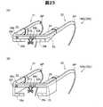
図23は、変形例におけるHMD100の外観構成を示す説明図である。図23(A)の例の場合、図1に示したHMD100との違いは、画像表示部20bが、右光学像表示部26に代えて右光学像表示部26bを備える点と、左光学像表示部28に代えて左光学像表示部28bを備える点である。右光学像表示部26bは、上記実施形態の光学部材よりも小さく形成され、HMD100bの装着時における使用者の右眼の斜め上に配置されている。同様に、左光学像表示部28bは、上記実施形態の光学部材よりも小さく形成され、HMD100bの装着時における使用者の左眼の斜め上に配置されている。図23(B)の例の場合、図1に示したHMD100との違いは、画像表示部20cが、右光学像表示部26に代えて右光学像表示部26cを備える点と、左光学像表示部28に代えて左光学像表示部28cを備える点である。右光学像表示部26cは、上記実施形態の光学部材よりも小さく形成され、ヘッドマウントディスプレイの装着時における使用者の右眼の斜め下に配置されている。左光学像表示部28cは、上記実施形態の光学部材よりも小さく形成され、ヘッドマウントディスプレイの装着時における使用者の左眼の斜め下に配置されている。このように、光学像表示部は使用者の眼の近傍に配置されていれば足りる。また、光学像表示部を形成する光学部材の大きさも任意であり、光学像表示部が使用者の眼の一部分のみを覆う態様、換言すれば、光学像表示部が使用者の眼を完全に覆わない態様のHMD100として実現できる。 FIG. 23 is an explanatory diagram showing an external configuration of the
また、イヤホンは耳掛け型やヘッドバンド型を採用してもよく、省略してもよい。また、例えば、自動車や飛行機等の車両に搭載されるヘッドマウントディスプレイとして構成されてもよい。また、例えば、ヘルメット等の身体防護具に内蔵されたヘッドマウントディスプレイとして構成されてもよい。 The earphone may be an ear-hook type or a headband type, or may be omitted. Further, for example, it may be configured as a head mounted display mounted on a vehicle such as an automobile or an airplane. Further, for example, it may be configured as a head-mounted display built in a body protective device such as a helmet.
上記実施形態におけるHMD100の構成は、あくまで一例であり、種々変形可能である。例えば、制御部10に設けられた方向キー16やトラックパッド14の一方を省略したり、方向キー16やトラックパッド14に加えてまたは方向キー16やトラックパッド14に代えて操作用スティック等の他の操作用インターフェイスを設けたりしてもよい。また、制御部10は、キーボードやマウス等の入力デバイスを接続可能な構成であり、キーボードやマウスから入力を受け付けるものとしてもよい。 The configuration of the
また、画像表示部として、眼鏡のように装着する画像表示部20に代えて、例えば帽子のように装着する画像表示部といった他の方式の画像表示部が採用されてもよい。また、イヤホン32,34は適宜省略可能である。 In addition, instead of the
また、上記実施形態において、HMD100は、使用者の左右の眼に同じ画像を表わす画像光を導いて使用者に二次元画像を視認させるとしてもよいし、使用者の左右の眼に異なる画像を表わす画像光を導いて使用者に三次元画像を視認させるとしてもよい。 In the above-described embodiment, the
また、上記実施形態において、ハードウェアによって実現されていた構成の一部をソフトウェアに置き換えるようにしてもよく、逆に、ソフトウェアによって実現されていた構成の一部をハードウェアに置き換えるようにしてもよい。例えば、上記実施形態では、画像処理部160や音声処理部170は、CPU140がコンピュータープログラムを読み出して実行することにより実現されるとしているが、これらの機能部はハードウェア回路により実現されるとしてもよい。例えば、上記実施形態の制御部10が備える構成のいくつかは、本発明の機能を実現するために設計されたASIC(Application Specific Integrated Circuit)を用いて構成されてもよい。 In the above embodiment, a part of the configuration realized by hardware may be replaced by software, and conversely, a part of the configuration realized by software may be replaced by hardware. Good. For example, in the above-described embodiment, the
また、本発明の機能の一部または全部がソフトウェアで実現される場合には、そのソフトウェア(コンピュータープログラム)は、コンピューター読み取り可能な記録媒体に格納された形で提供することができる。この発明において、「コンピューター読み取り可能な記録媒体」とは、フレキシブルディスクやCD−ROMのような携帯型の記録媒体に限らず、各種のRAMやROM等のコンピューター内の内部記憶装置や、ハードディスク等のコンピューターに固定されている外部記憶装置も含んでいる。 In addition, when part or all of the functions of the present invention are realized by software, the software (computer program) can be provided in a form stored in a computer-readable recording medium. In the present invention, the “computer-readable recording medium” is not limited to a portable recording medium such as a flexible disk or a CD-ROM, but an internal storage device in a computer such as various RAMs and ROMs, a hard disk, etc. It also includes an external storage device fixed to the computer.
また、上記実施形態では、図1および図2に示すように、制御部10と画像表示部20とが別々の構成として形成されているが、制御部10と画像表示部20との構成については、これに限られず、種々変形可能である。例えば、画像表示部20の内部に、制御部10に形成された構成の全てが形成されてもよいし、一部が形成されてもよい。また、上記実施形態における電源130が単独で形成されて、交換可能な構成であってもよいし、制御部10に形成された構成が重複して画像表示部20に形成されていてもよい。例えば、図2に示すCPU140が制御部10と画像表示部20との両方に形成されていてもよいし、制御部10に形成されたCPU140と画像表示部20に形成されたCPUとが行なう機能が別々に分けられている構成としてもよい。 Moreover, in the said embodiment, as shown in FIG. 1 and FIG. 2, the
また、制御部10と画像表示部20とが一体化して、使用者の衣服に取り付けられるウェアラブルコンピューターの態様であってもよい。 Moreover, the aspect of the wearable computer with which the
本発明は、上記実施形態や変形例に限られるものではなく、その趣旨を逸脱しない範囲において種々の構成で実現することができる。例えば、発明の概要の欄に記載した各形態中の技術的特徴に対応する実施形態、変形例中の技術的特徴は、上述の課題の一部または全部を解決するために、あるいは、上述の効果の一部または全部を達成するために、適宜、差し替えや、組み合わせを行なうことが可能である。また、その技術的特徴が本明細書中に必須なものとして説明されていなければ、適宜、削除することが可能である。 The present invention is not limited to the above-described embodiments and modifications, and can be realized with various configurations without departing from the spirit of the present invention. For example, the technical features in the embodiments and the modifications corresponding to the technical features in each form described in the summary section of the invention are to solve some or all of the above-described problems, or In order to achieve part or all of the effects, replacement or combination can be performed as appropriate. Further, if the technical feature is not described as essential in the present specification, it can be deleted as appropriate.
10…制御部
11…決定キー
12…点灯部
13…表示切替キー
14…トラックパッド
15…輝度切替キー
16…方向キー
17…メニューキー
18…電源スイッチ
20…画像表示部
21…右保持部
22…右表示駆動部
23…左保持部
24…左表示駆動部
26…右光学像表示部
28…左光学像表示部
30…イヤホンプラグ
32…右イヤホン
34…左イヤホン
40…接続部
42…右コード
44…左コード
46…連結部材
48…本体コード
51,52…送信部
53,54…受信部
61…カメラ(撮像部)
63…TOFセンサー
64…赤外線LED
69…マイク(音声取得部)
70…外部センサー(特定のオブジェクト)
100…HMD(頭部装着型表示装置)
120…記憶部
130…電源
132…無線通信部(第2の通信部)
135…操作部
140…CPU
150…OS
160…画像処理部
161…識別部(識別部)
163…位置特定部
165…画像設定部(制御部)
166…距離測定部(距離特定部)
168…画像判定部(画像検出部)
170…音声処理部(制御部)
180…インターフェイス
190…表示制御部
201…右バックライト制御部
202…左バックライト制御部
211…右LCD制御部
212…左LCD制御部
221…右バックライト
222…左バックライト
241…右LCD
242…左LCD
251…右投写光学系
252…左投写光学系
261…右導光板
262…左導光板
300…制御装置(制御実行部)
310…CPU
312…情報処理部
314…制御処理部
320…記憶部(対象物特定部)
330…無線通信部(第1の通信部)
340…被制御部
400…サーバー
420…記憶部
500…制御システム
OA…外部機器
MC…制御機器
SC…外景
RE…右眼
LE…左眼
EL…端部
IL…照明光
PL…画像光
LM…ランプ群
PN…画像表示最大領域
AP…先端部
ER…端部
VR…視野
BT…ボタン群
SW…スイッチ(対象物)
RC1,RC2…リモコン(対象物)
HD1…右手
FF1…人差し指(特定のオブジェクト)
IM1,IM2,IM3,IM4,IM5,IM6,IM7,IM8,IM9,IM10…画像
CS1,CS2…矢印画像(対象物対応虚像)
MT1,MT2…メーター(対象物)
TV1…テレビ
TX1,TX2,…テキスト画像(対象物対応虚像)
TX3,TX4…テキスト画像(特定確認画像)
AC…エアコン
IB…情報発信部
MK1,MK2,MK3…対応マーカー
VI…鳥瞰図
ey…撮像範囲DESCRIPTION OF
63 ...
69 ... Microphone (voice acquisition unit)
70 ... External sensor (specific object)
100 ... HMD (head-mounted display device)
120:
135:
150 ... OS
160: Image processing unit 161: Identification unit (identification unit)
163 ...
166 ... Distance measuring unit (distance specifying unit)
168 ... Image determination unit (image detection unit)
170 ... voice processing unit (control unit)
180 ... interface 190 ...
242 ... Left LCD
251 ... Right projection
310 ... CPU
312 ...
330 ... wireless communication unit (first communication unit)
340 ...
RC1, RC2 ... Remote control (object)
HD1 ... right hand FF1 ... index finger (specific object)
IM1, IM2, IM3, IM4, IM5, IM6, IM7, IM8, IM9, IM10 ... image CS1, CS2 ... arrow image (virtual image corresponding to the object)
MT1, MT2 ... Meter (object)
TV1 ... TV TX1, TX2, ... Text image (virtual image corresponding to the object)
TX3, TX4 ... Text image (specific confirmation image)
AC ... Air conditioner IB ... Information transmitter MK1, MK2, MK3 ... Corresponding marker VI ... Bird's eye view ey ... Imaging range
Claims (18)
Translated fromJapanese虚像を表示し、外景を透過可能な画像表示部と、
前記画像表示部から所定の距離の範囲にある選択可能な対象物と、前記外景に含まれる特定のオブジェクトの位置と、を取得する対象取得部と、
取得された前記対象物に対応付けられている対象物対応虚像を、前記画像表示部を用いて前記虚像として表示し、取得された前記特定のオブジェクトの位置に基づいて前記特定のオブジェクトの位置の変化を特定し、特定した前記特定のオブジェクトの位置の変化と取得された前記対象物の位置との関係に基づいて前記対象物を選択し、選択した前記対象物に対応付けられている特定確認画像を、前記画像表示部を用いて前記虚像として表示する制御部と、を備える、頭部装着型表示装置。A transmissive head-mounted display device,
An image display unit that displays a virtual image and transmits the outside scene;
A target acquisition unit that acquires a selectable target within a predetermined distance from the image display unit, and a position of a specific object included in the outside scene;
An object corresponding virtual image associated with the acquired object is displayed as the virtual image using the image display unit, and the position of the specific object is determined based on the acquired position of the specific object. The change is identified, the object is selected based on the relationship between the position change of the identified specific object and the acquired position of the object, and the identification confirmation associated with the selected object A head-mounted display device comprising: a control unit that displays an image as the virtual image using the image display unit.
前記対象取得部は、前記外景を撮像する撮像部と、撮像された前記外景に含まれる前記特定のオブジェクトの位置と前記対象物とを検出して取得する画像検出部と、を有し、
前記制御部は、選択した前記対象物の制御を決定し、決定した前記対象物の制御を実行する、頭部装着型表示装置。The head-mounted display device according to claim 1,
The target acquisition unit includes an imaging unit that images the outside scene, and an image detection unit that detects and acquires the position of the specific object and the target object included in the captured outside scene,
The head-mounted display device, wherein the control unit determines control of the selected object and executes control of the determined object.
前記制御部は、取得された前記特定のオブジェクトの位置と取得された前記対象物との組み合わせに予め対応付けられている前記対象物対応虚像を、前記画像表示部を用いて前記虚像として表示する、頭部装着型表示装置。The head-mounted display device according to claim 2,
The control unit displays the object-corresponding virtual image associated in advance with a combination of the acquired position of the specific object and the acquired object as the virtual image using the image display unit. Head mounted display device.
前記制御部は、取得された前記特定のオブジェクトの位置と取得された前記対象物との組み合わせに予め対応付けられている前記対象物対応虚像として、前記対象物の制御を実行するために必要な前記特定のオブジェクトの位置の変化を示す前記虚像を、前記画像表示部を用いて表示する、頭部装着型表示装置。The head-mounted display device according to claim 3,
The control unit is necessary to execute control of the object as the object-corresponding virtual image previously associated with a combination of the acquired position of the specific object and the acquired object. A head-mounted display device that displays the virtual image indicating a change in position of the specific object using the image display unit.
前記制御部は、取得された前記対象物に予め対応付けられている前記対象物対応虚像として、実行する前記対象物の制御の内容を示す前記虚像を、前記画像表示部を用いて表示する、頭部装着型表示装置。The head-mounted display device according to any one of claims 2 to 4,
The control unit displays, using the image display unit, the virtual image indicating the content of control of the target to be executed as the target corresponding virtual image previously associated with the acquired target. Head-mounted display device.
前記制御部は、撮像された前記外景において、前記特定のオブジェクトの変化後の位置と前記対象物とが重なっている場合に、前記特定のオブジェクトの変化後の位置と重なっている前記対象物に予め対応付けられている前記対象物の制御を決定する、頭部装着型表示装置。A head-mounted display device according to any one of claims 2 to 5,
When the position after the change of the specific object overlaps the target object in the imaged outside scene, the control unit applies the target object that overlaps the position after the change of the specific object. A head-mounted display device that determines control of the object associated in advance.
取得された前記対象物と前記画像表示部との距離を特定する距離特定部を備え、
前記制御部は、取得されると共に特定された前記距離が閾値以下の前記対象物を、選択可能な前記対象物として設定する、頭部装着型表示装置。The head-mounted display device according to any one of claims 2 to 6, further comprising:
A distance specifying unit that specifies a distance between the acquired object and the image display unit;
The control unit is a head-mounted display device that sets, as the selectable object, the object whose acquired distance is equal to or less than a threshold value.
外部の音声を取得する音声取得部を備え、
前記制御部は、特定された前記特定のオブジェクトの位置の変化と取得された前記音声との組み合わせに基づいて前記対象物の制御を決定する、頭部装着型表示装置。The head-mounted display device according to any one of claims 2 to 7, further comprising:
It has an audio acquisition unit that acquires external audio,
The head-mounted display device, wherein the control unit determines control of the object based on a combination of a change in position of the specified object specified and the acquired sound.
前記対象取得部は、他の装置から少なくとも1つの前記対象物の位置情報を取得する、頭部装着型表示装置。The head-mounted display device according to claim 1,
The target acquisition unit is a head-mounted display device that acquires position information of at least one of the objects from another device.
前記制御部は、取得された前記対象物が前記外景に含まれない場合に、前記画像表示部を用いて、前記画像表示部と取得された前記対象物との位置関係を前記虚像として表示する、頭部装着型表示装置。The head-mounted display device according to claim 9,
The control unit displays the positional relationship between the image display unit and the acquired object as the virtual image using the image display unit when the acquired object is not included in the outside scene. Head mounted display device.
前記制御部は、前記特定のオブジェクトの加速度を検出し、検出した前記特定のオブジェクトの加速度に基づいて、前記特定のオブジェクトの位置の変化を特定する、頭部装着型表示装置。The head-mounted display device according to any one of claims 1 to 10,
The head-mounted display device, wherein the control unit detects an acceleration of the specific object, and specifies a change in a position of the specific object based on the detected acceleration of the specific object.
外部の音声を取得する音声取得部を備え、
前記制御部は、取得された前記外部の音声と、特定された前記特定のオブジェクトの位置の変化との組み合わせに基づいて、選択した前記対象物の制御を決定する、頭部装着型表示装置。The head-mounted display device according to claim 11, further comprising:
It has an audio acquisition unit that acquires external audio,
The head-mounted display device, wherein the control unit determines control of the selected object based on a combination of the acquired external sound and a change in the position of the specified specific object.
前記制御部は、選択した前記対象物に対応付けられた制御装置の制御を実行し、前記外景に選択した前記対象物と前記制御装置とが取得される場合に、前記画像表示部を用いて、選択した前記対象物と前記制御装置とが対応関係にあることを前記虚像として表示する、頭部装着型表示装置。The head-mounted display device according to any one of claims 1 to 12,
The control unit executes control of the control device associated with the selected object, and when the object selected as the outside scene and the control device are acquired, the image display unit is used. A head-mounted display device that displays, as the virtual image, that the selected object and the control device are in a correspondence relationship.
前記制御部は、選択した前記対象物と前記制御装置とが対応関係にあることを示す前記虚像として、前記画像表示部を用いて、同じ形で同じ色の虚像を表示する、頭部装着型表示装置。The head-mounted display device according to claim 13,
The control unit displays a virtual image of the same color in the same shape using the image display unit as the virtual image indicating that the selected object and the control device are in a correspondence relationship. Display device.
前記画像表示部の使用者の属性を識別する識別部を備え、
前記制御部は、前記対象物に対応付けられている虚像と前記特定確認画像との少なくとも一方を、識別された前記属性に対応させて前記画像表示部を用いて前記虚像として表示する、頭部装着型表示装置。The head-mounted display device according to any one of claims 1 to 14, further comprising:
An identification unit for identifying an attribute of a user of the image display unit;
The control unit displays at least one of a virtual image associated with the object and the specific confirmation image as the virtual image using the image display unit in association with the identified attribute. Wearable display device.
前記対象物を特定する対象物特定部と、
特定された前記対象物の情報を送信する第1の通信部と、
制御実行部と、を備え、
前記頭部装着型表示装置は、
送信された前記対象物の情報を受信し、決定された前記対象物の制御の情報を送信する第2の通信部を備え、
前記第1の通信部は、送信された前記対象物の制御の情報を受信し、
前記制御実行部は、前記第1の通信部によって受信された前記対象物の制御に基づく制御を実行する、制御システム。A control system including the head-mounted display device according to any one of claims 2 to 8,
An object specifying unit for specifying the object;
A first communication unit for transmitting information on the identified object;
A control execution unit,
The head-mounted display device is
A second communication unit that receives the transmitted information of the object and transmits the determined control information of the object;
The first communication unit receives the transmitted control information of the object,
The control execution unit executes control based on control of the object received by the first communication unit.
前記画像表示部から所定の距離の範囲にある選択可能な対象物と、前記外景に含まれる特定のオブジェクトの位置と、取得する工程と、
取得された前記対象物に対応付けられている対象物対応虚像を、前記画像表示部を用いて前記虚像として表示し、取得された前記特定のオブジェクトの位置に基づいて、前記特定のオブジェクトの位置の変化を特定し、特定した前記特定のオブジェクトの位置の変化と取得された前記対象物の位置との関係に基づいて前記対象物を選択し、選択した前記対象物に対応付けられた特定確認画像を、前記画像表示部を用いて前記虚像として表示する工程と、を備える、制御方法。A control method for a transmissive head-mounted display device that includes an image display unit that displays a virtual image and is able to transmit an outside scene,
A selectable object within a predetermined distance from the image display unit, a position of a specific object included in the outside scene, and a step of acquiring,
The object corresponding virtual image associated with the acquired object is displayed as the virtual image using the image display unit, and the position of the specific object is based on the acquired position of the specific object. Identifying the change, selecting the target based on the relationship between the change in the position of the specified specific object and the acquired position of the target, and identifying confirmation associated with the selected target And a step of displaying an image as the virtual image using the image display unit.
前記画像表示部から所定の距離の範囲にある選択可能な対象物と、前記外景に含まれる特定のオブジェクトの位置と、取得する対象取得機能と、
取得された前記対象物に対応付けられている対象物対応虚像を、前記画像表示部を用いて前記虚像として表示し、取得された前記特定のオブジェクトの位置に基づいて、前記特定のオブジェクトの位置の変化を特定し、特定した前記特定のオブジェクトの位置の変化と取得された前記対象物の位置との関係に基づいて前記対象物を選択し、選択した前記対象物に対応付けられた特定確認画像を、前記画像表示部を用いて前記虚像として表示する制御機能と、をコンピューターに実現させるコンピュータープログラム。A computer program for a transmissive head-mounted display device that includes an image display unit that displays a virtual image and is capable of transmitting an outside scene.
A selectable target within a predetermined distance from the image display unit, a position of a specific object included in the outside scene, and a target acquisition function to acquire;
The object corresponding virtual image associated with the acquired object is displayed as the virtual image using the image display unit, and the position of the specific object is based on the acquired position of the specific object. Identifying the change, selecting the target based on the relationship between the change in the position of the specified specific object and the acquired position of the target, and identifying confirmation associated with the selected target A computer program that causes a computer to realize a control function of displaying an image as the virtual image using the image display unit.
Priority Applications (4)
| Application Number | Priority Date | Filing Date | Title |
|---|---|---|---|
| JP2015024971AJP6500477B2 (en) | 2015-02-12 | 2015-02-12 | Head-mounted display device, control system, control method of head-mounted display device, and computer program |
| US14/682,409US9766715B2 (en) | 2014-05-01 | 2015-04-09 | Head-mount type display device, control system, method of controlling head-mount type display device, and computer program |
| CN201510180796.8ACN105045375B (en) | 2014-05-01 | 2015-04-16 | Head-mounted display device, control method therefor, control system, and computer program |
| US15/672,846US9965048B2 (en) | 2014-05-01 | 2017-08-09 | Head-mount type display device, control system, method of controlling head-mount type display device, and computer program |
Applications Claiming Priority (1)
| Application Number | Priority Date | Filing Date | Title |
|---|---|---|---|
| JP2015024971AJP6500477B2 (en) | 2015-02-12 | 2015-02-12 | Head-mounted display device, control system, control method of head-mounted display device, and computer program |
Publications (2)
| Publication Number | Publication Date |
|---|---|
| JP2016148968Atrue JP2016148968A (en) | 2016-08-18 |
| JP6500477B2 JP6500477B2 (en) | 2019-04-17 |
Family
ID=56691237
Family Applications (1)
| Application Number | Title | Priority Date | Filing Date |
|---|---|---|---|
| JP2015024971AActiveJP6500477B2 (en) | 2014-05-01 | 2015-02-12 | Head-mounted display device, control system, control method of head-mounted display device, and computer program |
Country Status (1)
| Country | Link |
|---|---|
| JP (1) | JP6500477B2 (en) |
Cited By (20)
| Publication number | Priority date | Publication date | Assignee | Title |
|---|---|---|---|---|
| JP2018142171A (en)* | 2017-02-28 | 2018-09-13 | 京セラドキュメントソリューションズ株式会社 | Product ordering system, product ordering method, image forming device, and electronic apparatus |
| WO2019021566A1 (en)* | 2017-07-26 | 2019-01-31 | ソニー株式会社 | Information processing device, information processing method, and program |
| JP2019061455A (en)* | 2017-09-26 | 2019-04-18 | 株式会社Nttドコモ | INFORMATION PROCESSING DEVICE, TERMINAL DEVICE, AND INFORMATION PROCESSING SYSTEM |
| JP2019149066A (en)* | 2018-02-28 | 2019-09-05 | 富士ゼロックス株式会社 | Information processing apparatus and program |
| JP2019207573A (en)* | 2018-05-29 | 2019-12-05 | 富士ゼロックス株式会社 | Information processing device and program |
| JP2020505686A (en)* | 2017-01-17 | 2020-02-20 | コーニンクレッカ フィリップス エヌ ヴェKoninklijke Philips N.V. | Augmented reality for predictive workflow in the operating room |
| JP2020513618A (en)* | 2016-12-05 | 2020-05-14 | マジック リープ, インコーポレイテッドMagic Leap,Inc. | Virtual User Input Control in Mixed Reality Environment |
| JP2020527767A (en)* | 2017-05-25 | 2020-09-10 | インターナショナル・ビジネス・マシーンズ・コーポレーションInternational Business Machines Corporation | Augmented reality for ease of accessibility |
| JP2020181545A (en)* | 2019-04-23 | 2020-11-05 | 未來市股▲ふん▼有限公司 | Head mounted display system capable of assigning at least one predetermined interactive characteristic to virtual object in virtual environment created according to real object in real environment, related method, and related non-transitory computer readable storage medium |
| JP2021149296A (en)* | 2020-03-17 | 2021-09-27 | 日本ユニシス株式会社 | System for visualizing clustering to actual object, visualization control unit, visualization method, and program for visualization control |
| JP2022017706A (en)* | 2020-07-14 | 2022-01-26 | 株式会社東海理化電機製作所 | Wearable terminal, gesture method display system and display method for gesture method |
| KR20220031896A (en)* | 2019-06-18 | 2022-03-14 | 휴메인, 인코포레이티드 | Wearable Multimedia Device and Cloud Computing Platform with Laser Projection System |
| US11334765B2 (en) | 2017-07-26 | 2022-05-17 | Magic Leap, Inc. | Training a neural network with representations of user interface devices |
| JP2022107645A (en)* | 2018-06-25 | 2022-07-22 | グーグル エルエルシー | Identification and control of smart device |
| JP2023157968A (en)* | 2020-10-30 | 2023-10-26 | 株式会社Mixi | Head-mounted display device, authentication method, and authentication program |
| JP2024518878A (en)* | 2021-05-10 | 2024-05-08 | インターナショナル・ビジネス・マシーンズ・コーポレーション | Creating a Virtual Context for Voice Commands |
| JP2024123273A (en)* | 2020-07-08 | 2024-09-10 | マクセル株式会社 | Remote Control Method |
| US12225284B2 (en) | 2017-05-10 | 2025-02-11 | Humane, Inc. | Wearable multimedia device and cloud computing platform with application ecosystem |
| WO2025146728A1 (en)* | 2024-01-05 | 2025-07-10 | ソニーグループ株式会社 | Information processing device, information processing program, and information processing method |
| JP7755002B2 (en) | 2024-07-02 | 2025-10-15 | マクセル株式会社 | Remote Control Method |
Citations (7)
| Publication number | Priority date | Publication date | Assignee | Title |
|---|---|---|---|---|
| JP2011180867A (en)* | 2010-03-02 | 2011-09-15 | Brother Industries Ltd | Head-mounted display |
| JP2011209965A (en)* | 2010-03-29 | 2011-10-20 | Sony Corp | Information processor, information processing method and program |
| JP2013172432A (en)* | 2012-02-23 | 2013-09-02 | Panasonic Corp | Equipment control apparatus, equipment control method, equipment control program, and integrated circuit |
| WO2014045683A1 (en)* | 2012-09-21 | 2014-03-27 | ソニー株式会社 | Control device and recording medium |
| JP2014115457A (en)* | 2012-12-10 | 2014-06-26 | Sony Corp | Information processing apparatus and recording medium |
| JP2014203153A (en)* | 2013-04-02 | 2014-10-27 | パイオニア株式会社 | Display control device |
| WO2014196038A1 (en)* | 2013-06-05 | 2014-12-11 | 三菱電機株式会社 | Device for processing information through line-of-sight detection and information processing method |
- 2015
- 2015-02-12JPJP2015024971Apatent/JP6500477B2/enactiveActive
Patent Citations (8)
| Publication number | Priority date | Publication date | Assignee | Title |
|---|---|---|---|---|
| JP2011180867A (en)* | 2010-03-02 | 2011-09-15 | Brother Industries Ltd | Head-mounted display |
| JP2011209965A (en)* | 2010-03-29 | 2011-10-20 | Sony Corp | Information processor, information processing method and program |
| JP2013172432A (en)* | 2012-02-23 | 2013-09-02 | Panasonic Corp | Equipment control apparatus, equipment control method, equipment control program, and integrated circuit |
| WO2014045683A1 (en)* | 2012-09-21 | 2014-03-27 | ソニー株式会社 | Control device and recording medium |
| US20150227222A1 (en)* | 2012-09-21 | 2015-08-13 | Sony Corporation | Control device and storage medium |
| JP2014115457A (en)* | 2012-12-10 | 2014-06-26 | Sony Corp | Information processing apparatus and recording medium |
| JP2014203153A (en)* | 2013-04-02 | 2014-10-27 | パイオニア株式会社 | Display control device |
| WO2014196038A1 (en)* | 2013-06-05 | 2014-12-11 | 三菱電機株式会社 | Device for processing information through line-of-sight detection and information processing method |
Cited By (41)
| Publication number | Priority date | Publication date | Assignee | Title |
|---|---|---|---|---|
| US12175054B2 (en) | 2016-12-05 | 2024-12-24 | Magic Leap, Inc. | Virtual user input controls in a mixed reality environment |
| JP2023153357A (en)* | 2016-12-05 | 2023-10-17 | マジック リープ, インコーポレイテッド | Virtual user input control in mixed reality environment |
| JP7339392B2 (en) | 2016-12-05 | 2023-09-05 | マジック リープ, インコーポレイテッド | Virtual User Input Control in Mixed Reality Environment |
| JP2020513618A (en)* | 2016-12-05 | 2020-05-14 | マジック リープ, インコーポレイテッドMagic Leap,Inc. | Virtual User Input Control in Mixed Reality Environment |
| US11720223B2 (en) | 2016-12-05 | 2023-08-08 | Magic Leap, Inc. | Virtual user input controls in a mixed reality environment |
| JP7112399B2 (en) | 2016-12-05 | 2022-08-03 | マジック リープ, インコーポレイテッド | Virtual User Input Control in Mixed Reality Environment |
| JP2022097726A (en)* | 2016-12-05 | 2022-06-30 | マジック リープ, インコーポレイテッド | Virtual user input control in mixed reality environment |
| JP7720364B2 (en) | 2016-12-05 | 2025-08-07 | マジック リープ, インコーポレイテッド | Virtual User Input Control in Mixed Reality Environments |
| JP7004729B2 (en) | 2017-01-17 | 2022-01-21 | コーニンクレッカ フィリップス エヌ ヴェ | Augmented reality for predictive workflows in the operating room |
| JP2020505686A (en)* | 2017-01-17 | 2020-02-20 | コーニンクレッカ フィリップス エヌ ヴェKoninklijke Philips N.V. | Augmented reality for predictive workflow in the operating room |
| JP2018142171A (en)* | 2017-02-28 | 2018-09-13 | 京セラドキュメントソリューションズ株式会社 | Product ordering system, product ordering method, image forming device, and electronic apparatus |
| US12244922B2 (en) | 2017-05-10 | 2025-03-04 | Humane, Inc. | Wearable multimedia device and cloud computing platform with application ecosystem |
| US12225284B2 (en) | 2017-05-10 | 2025-02-11 | Humane, Inc. | Wearable multimedia device and cloud computing platform with application ecosystem |
| US12230029B2 (en) | 2017-05-10 | 2025-02-18 | Humane, Inc. | Wearable multimedia device and cloud computing platform with laser projection system |
| JP2020527767A (en)* | 2017-05-25 | 2020-09-10 | インターナショナル・ビジネス・マシーンズ・コーポレーションInternational Business Machines Corporation | Augmented reality for ease of accessibility |
| US11630314B2 (en) | 2017-07-26 | 2023-04-18 | Magic Leap, Inc. | Training a neural network with representations of user interface devices |
| US11334765B2 (en) | 2017-07-26 | 2022-05-17 | Magic Leap, Inc. | Training a neural network with representations of user interface devices |
| WO2019021566A1 (en)* | 2017-07-26 | 2019-01-31 | ソニー株式会社 | Information processing device, information processing method, and program |
| JP2019061455A (en)* | 2017-09-26 | 2019-04-18 | 株式会社Nttドコモ | INFORMATION PROCESSING DEVICE, TERMINAL DEVICE, AND INFORMATION PROCESSING SYSTEM |
| US11514705B2 (en) | 2018-02-28 | 2022-11-29 | Fujifilm Business Innovation Corp. | Information processing apparatus and non-transitory computer readable medium to allow operation without contact |
| JP2019149066A (en)* | 2018-02-28 | 2019-09-05 | 富士ゼロックス株式会社 | Information processing apparatus and program |
| JP7135444B2 (en) | 2018-05-29 | 2022-09-13 | 富士フイルムビジネスイノベーション株式会社 | Information processing device and program |
| JP2019207573A (en)* | 2018-05-29 | 2019-12-05 | 富士ゼロックス株式会社 | Information processing device and program |
| JP2022107645A (en)* | 2018-06-25 | 2022-07-22 | グーグル エルエルシー | Identification and control of smart device |
| US11921988B2 (en) | 2018-06-25 | 2024-03-05 | Google Llc | Identifying and controlling smart devices |
| JP2020181545A (en)* | 2019-04-23 | 2020-11-05 | 未來市股▲ふん▼有限公司 | Head mounted display system capable of assigning at least one predetermined interactive characteristic to virtual object in virtual environment created according to real object in real environment, related method, and related non-transitory computer readable storage medium |
| US11107293B2 (en) | 2019-04-23 | 2021-08-31 | XRSpace CO., LTD. | Head mounted display system capable of assigning at least one predetermined interactive characteristic to a virtual object in a virtual environment created according to a real object in a real environment, a related method and a related non-transitory computer readable storage medium |
| JP7508492B2 (en) | 2019-06-18 | 2024-07-01 | ヒューメイン・インコーポレイテッド | Cloud Computing Platform with Wearable Multimedia Device and Laser Projection System |
| JP2022537574A (en)* | 2019-06-18 | 2022-08-26 | ヒューメイン・インコーポレイテッド | Cloud computing platform with wearable multimedia device and laser projection system |
| KR102859393B1 (en)* | 2019-06-18 | 2025-09-12 | 휴메인, 인코포레이티드 | Wearable multimedia device and cloud computing platform with laser projection system |
| JP2024050736A (en)* | 2019-06-18 | 2024-04-10 | ヒューメイン・インコーポレイテッド | Cloud Computing Platform with Wearable Multimedia Device and Laser Projection System |
| KR20220031896A (en)* | 2019-06-18 | 2022-03-14 | 휴메인, 인코포레이티드 | Wearable Multimedia Device and Cloud Computing Platform with Laser Projection System |
| JP7374413B2 (en) | 2020-03-17 | 2023-11-07 | Biprogy株式会社 | Clustering visualization system for real objects, visualization control device, visualization method, and visualization control program |
| JP2021149296A (en)* | 2020-03-17 | 2021-09-27 | 日本ユニシス株式会社 | System for visualizing clustering to actual object, visualization control unit, visualization method, and program for visualization control |
| JP2024123273A (en)* | 2020-07-08 | 2024-09-10 | マクセル株式会社 | Remote Control Method |
| JP2022017706A (en)* | 2020-07-14 | 2022-01-26 | 株式会社東海理化電機製作所 | Wearable terminal, gesture method display system and display method for gesture method |
| JP2023157968A (en)* | 2020-10-30 | 2023-10-26 | 株式会社Mixi | Head-mounted display device, authentication method, and authentication program |
| JP7583318B2 (en) | 2020-10-30 | 2024-11-14 | 株式会社Mixi | Head-mounted display device, authentication method, and authentication program |
| JP2024518878A (en)* | 2021-05-10 | 2024-05-08 | インターナショナル・ビジネス・マシーンズ・コーポレーション | Creating a Virtual Context for Voice Commands |
| WO2025146728A1 (en)* | 2024-01-05 | 2025-07-10 | ソニーグループ株式会社 | Information processing device, information processing program, and information processing method |
| JP7755002B2 (en) | 2024-07-02 | 2025-10-15 | マクセル株式会社 | Remote Control Method |
Also Published As
| Publication number | Publication date |
|---|---|
| JP6500477B2 (en) | 2019-04-17 |
Similar Documents
| Publication | Publication Date | Title |
|---|---|---|
| JP6500477B2 (en) | Head-mounted display device, control system, control method of head-mounted display device, and computer program | |
| US9965048B2 (en) | Head-mount type display device, control system, method of controlling head-mount type display device, and computer program | |
| JP6427942B2 (en) | Head-mounted display device, control system, and head-mounted display device control method | |
| US9921646B2 (en) | Head-mounted display device and method of controlling head-mounted display device | |
| JP6237000B2 (en) | Head-mounted display device | |
| JP5970872B2 (en) | Head-mounted display device and method for controlling head-mounted display device | |
| JP6232763B2 (en) | Head-mounted display device and method for controlling head-mounted display device | |
| JP6277673B2 (en) | Head-mounted display device and method for controlling head-mounted display device | |
| JP6264871B2 (en) | Information processing apparatus and information processing apparatus control method | |
| JP6303274B2 (en) | Head-mounted display device and method for controlling head-mounted display device | |
| JP6600945B2 (en) | Head-mounted display device, head-mounted display device control method, and computer program | |
| JP6318596B2 (en) | Information processing apparatus and information processing apparatus control method | |
| JP2016004340A (en) | Information distribution system, head-mounted type display device, control method of head-mounted type display device and computer program | |
| CN104423046A (en) | Image processing device and head mounted display apparatus including the same | |
| JP6488786B2 (en) | Head-mounted display device, head-mounted display device control method, and computer program | |
| JP2016024208A (en) | Display device, method for controlling display device, and program | |
| JP2016082466A (en) | Head-mounted display device, head-mounted display device control method, and computer program | |
| JP6135162B2 (en) | Head-mounted display device, head-mounted display device control method, and image display system | |
| JP2015019274A (en) | Head-mounted display device and method for controlling head-mounted display device | |
| JP2016212769A (en) | Display device, control method for the same and program | |
| JP6669183B2 (en) | Head mounted display and control method of head mounted display | |
| JP6308249B2 (en) | Head-mounted display device and method | |
| JP2017157120A (en) | Display device and control method of display device | |
| JP2017191424A (en) | Head-mounted display device |
Legal Events
| Date | Code | Title | Description |
|---|---|---|---|
| A621 | Written request for application examination | Free format text:JAPANESE INTERMEDIATE CODE: A621 Effective date:20171114 | |
| A977 | Report on retrieval | Free format text:JAPANESE INTERMEDIATE CODE: A971007 Effective date:20180726 | |
| A131 | Notification of reasons for refusal | Free format text:JAPANESE INTERMEDIATE CODE: A131 Effective date:20180731 | |
| A521 | Request for written amendment filed | Free format text:JAPANESE INTERMEDIATE CODE: A523 Effective date:20180925 | |
| TRDD | Decision of grant or rejection written | ||
| A01 | Written decision to grant a patent or to grant a registration (utility model) | Free format text:JAPANESE INTERMEDIATE CODE: A01 Effective date:20190219 | |
| A61 | First payment of annual fees (during grant procedure) | Free format text:JAPANESE INTERMEDIATE CODE: A61 Effective date:20190304 | |
| R150 | Certificate of patent or registration of utility model | Ref document number:6500477 Country of ref document:JP Free format text:JAPANESE INTERMEDIATE CODE: R150 |