JP2016148922A - Upload system and upload method - Google Patents
Upload system and upload methodDownload PDFInfo
- Publication number
- JP2016148922A JP2016148922AJP2015024326AJP2015024326AJP2016148922AJP 2016148922 AJP2016148922 AJP 2016148922AJP 2015024326 AJP2015024326 AJP 2015024326AJP 2015024326 AJP2015024326 AJP 2015024326AJP 2016148922 AJP2016148922 AJP 2016148922A
- Authority
- JP
- Japan
- Prior art keywords
- data
- upload
- storage device
- storage
- transfer
- Prior art date
- Legal status (The legal status is an assumption and is not a legal conclusion. Google has not performed a legal analysis and makes no representation as to the accuracy of the status listed.)
- Pending
Links
Images


Landscapes
- Information Transfer Between Computers (AREA)
Abstract
Translated fromJapaneseDescription
Translated fromJapanese本発明は、アップロードシステム及びアップロード方法に関する。 The present invention relates to an upload system and an upload method.
近年、インターネット等のネットワークを介して、コンテンツのダウンロードを行わせるサービスが普及してきている。コンテンツは、動画等であり、大容量のデータである。このため、コンテンツのダウンロードは、大容量のデータを送信して帯域を多く利用するので、ネットワーク負荷が大きい。そこで、コンテンツのダウンロードの際に、IP(Internet Protocol)マルチキャスト配信やキャッシュサーバの設定により、ネットワーク負荷を分散させる技術がある。 In recent years, services for downloading contents via a network such as the Internet have become widespread. The content is a moving image or the like, and is a large amount of data. For this reason, downloading of contents uses a large amount of bandwidth by transmitting a large amount of data, so that the network load is heavy. Therefore, there is a technique for distributing the network load by downloading IP (Internet Protocol) multicast and setting a cache server when downloading content.
しかしながら、上記技術は、コンテンツのダウンロードの際にネットワーク負荷分散を図る技術に過ぎない。IPマルチキャストは、コンテンツを複製して多くのユーザに配信する技術であるため、ユーザ毎に異なるコンテンツをアップロードする場合にはIPマルチキャストのメリットを最大化できない。 However, the above technique is only a technique for distributing the network load when downloading content. Since IP multicast is a technology for copying content and distributing it to many users, when uploading different content for each user, the advantage of IP multicast cannot be maximized.
また、キャッシュサーバを利用する際には、アップロードのコンテンツをキャッシュサーバに送信する技術と、キャッシュサーバにコンテンツがアップロードされた後にアップロード先のストレージに同期する手法がない。 In addition, when using a cache server, there is no technique for transmitting the uploaded content to the cache server, and no method for synchronizing with the upload destination storage after the content is uploaded to the cache server.
このため、ユーザ自身が作成した動画等の大容量データをネットワーク上のストレージへアップロードする昨今のコンテンツサービスでは、従来の負荷分散手法を適用できないため、アップロードの際に帯域を消費するネットワーク負荷の問題がある。 For this reason, with the current content services that upload large volumes of data such as videos created by users to storage on the network, the conventional load balancing method cannot be applied, so the problem of network load that consumes bandwidth during uploading There is.
本願が開示する実施形態の一例は、上記に鑑みてなされたものであって、データのアップロードの際のネットワーク負荷を低減することを目的とする。 An example of an embodiment disclosed in the present application has been made in view of the above, and aims to reduce a network load at the time of uploading data.
本願が開示する実施形態の一例は、アップロードシステムは、データ格納装置、データ一時格納装置、第1の転送装置、第2の転送装置、管理装置を備える。データ格納装置は、アップロードデータを格納する。データ一時格納装置は、アップロードデータを一時格納する。第1の転送装置は、ユーザ端末からのアップロードデータを転送する。第2の転送装置は、第1の転送装置から転送されたデータ格納装置宛のアップロードデータをデータ格納装置へ転送する。管理装置は、第2の転送装置におけるネットワーク負荷が閾値を越える場合に、ユーザ端末からデータ格納装置宛のアップロードデータをデータ一時格納装置宛へ転送し、ネットワーク負荷が閾値を越えない場合に、アップロードデータをデータ格納装置宛として第2の転送装置へ転送するよう第1の転送装置を制御する。 In an example of the embodiment disclosed in the present application, an upload system includes a data storage device, a data temporary storage device, a first transfer device, a second transfer device, and a management device. The data storage device stores upload data. The data temporary storage device temporarily stores upload data. The first transfer device transfers upload data from the user terminal. The second transfer device transfers the upload data addressed to the data storage device transferred from the first transfer device to the data storage device. The management device transfers upload data addressed to the data storage device from the user terminal to the data temporary storage device when the network load in the second transfer device exceeds the threshold value, and uploads when the network load does not exceed the threshold value. The first transfer device is controlled to transfer data to the second transfer device as addressed to the data storage device.
本願が開示する実施形態の一例によれば、例えば、データのアップロードの際のネットワーク負荷を低減することができる。 According to an example of an embodiment disclosed in the present application, for example, it is possible to reduce a network load when data is uploaded.
[実施形態]
以下、本願が開示するアップロードシステム及びアップロード方法の実施形態を説明する。なお、以下の実施形態は、一例を示すに過ぎず、本願が開示する技術を限定するものではない。また、以下に示す実施形態及びその他の実施形態は、矛盾しない範囲で適宜組合せてもよい。[Embodiment]
Hereinafter, embodiments of an upload system and an upload method disclosed in the present application will be described. The following embodiments are merely examples, and do not limit the technology disclosed by the present application. Moreover, you may combine suitably embodiment shown below and other embodiment in the range with no contradiction.
(アップロードシステムの構成)
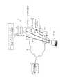
図1は、アップロードシステムの構成の一例を示す図である。アップロードシステム1は、ネットワーク2に接続される、ルータ3−1及び3−2、ポリシー制御サーバ4、アップロードサーバ5、ルータ3−2に接続されるストレージ6、ルータ3−1に接続されるユーザ端末7を含む。ネットワーク2は、例えば、大規模の公衆網又は閉域網である。ルータ3−1及び3−2を区別なく表記する際は、ルータ3と表記する。なお、図1に示すルータ3、アップロードサーバ5、ストレージ6、ユーザ端末7の数は、一例であり、図1に示す数に限られない。(Upload system configuration)
FIG. 1 is a diagram illustrating an example of the configuration of an upload system. The
ルータ3−1は、ユーザ端末7が接続される転送装置である。ユーザ端末7は、例えば、パーソナルコンピュータ、スマートフォン、タブレット端末、撮影機能又は録音機能を備えた機器等、ユーザエンドのコンピュータである。ルータ3−2は、ストレージ6が接続される転送装置である。ストレージ6は、アップロードされたコンテンツデータを保存し、保存するコンテンツデータを、ユーザ端末7等からの配信要求に応じて配信するコンテンツサーバであるデータ格納装置である。アップロードサーバ5は、ストレージ6へアップロードされるアップロードデータの転送を受付け、ストレージ6へアップロードされる前に、ストレージ6の代わりにアップロードデータを一時保存するキャッシュサーバであるデータ一時格納装置である。 The router 3-1 is a transfer device to which the
ユーザ端末7からストレージ6へアップロードされる、画像、動画、音声等のアップロードデータは、ルータ3−1、ネットワーク2、ルータ3−2を経由して、ストレージ6により受信される。ストレージ6は、受信したアップロードデータを自装置内に保存する。 Upload data such as images, moving images, and audio uploaded from the
また、ユーザ端末7からアップロードサーバ5へ転送される、画像、動画、音声等のアップロードデータは、ルータ3−1、ネットワーク2を経由して、アップロードサーバ5により受信される。アップロードサーバ5は、転送により受信したアップロードデータを自装置内に一時保存する。なお、アップロードサーバ5は、ユーザ端末7と同一又は近傍のネットワークセグメントに配置されることが望ましい。これは、ストレージ6へのトラヒック集中を分散する際に、ユーザエンドへトラヒックを分散させる方が、より分散効果が高いためである。 Also, upload data such as images, moving images, and voices transferred from the
ポリシー制御サーバ4は、例えばPCC(Policy and Charging Control)におけるPCRF(Policy and Charging Rules Function)、PCEF(Policy and Charging Enforcement Function)である管理装置である。ポリシー制御サーバ4は、ネットワーク2の利用状況又は負荷に応じて、ユーザ端末7からストレージ6へのアップロードデータをアップロードサーバ5へ転送するか否かを判定する。そして、ポリシー制御サーバ4は、ユーザ端末7からストレージ6へのアップロードデータをアップロードサーバ5へ転送する場合は、ルータ3−1に対して、ユーザ端末7からストレージ6へのアップロードデータを、アップロードサーバ5へ転送するよう指示する。なお、ルータ3−1及びポリシー制御サーバ4間の通信は、例えばDAIAMETER等の通信プロトコルを利用する。 The
また、ポリシー制御サーバ4は、ネットワーク2の利用状況又は負荷に応じて、アップロードサーバ5に一時保存されたアップロードデータをストレージ6へ送信するか否かを判定する。そして、ポリシー制御サーバ4は、アップロードサーバ5に一時保存されたアップロードデータをストレージ6へ送信する場合は、アップロードサーバ5に対して、自装置内に一時保存したアップロードデータを、ストレージ6へ送信するよう指示する。なお、アップロードサーバ5及びポリシー制御サーバ4間の通信は、例えばHTTP(Hypertext Transfer Protocol)、DAIAMETER等を通信プロトコルとする。 Further, the
(ルータの構成)
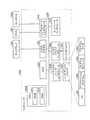
図2は、ルータの構成の一例を示す図である。ルータ3は、図1に示すように、ユーザ端末7がストレージ6へアップロードデータを送信する際に、ユーザ端末7からネットワーク2への入り口となるルータ3−1と、ネットワーク2からストレージ6への出口となるルータ3−2とを含む。ルータ3−1及び3−2は、同一の機能構成である。すなわち、ルータ3は、パケット受信部31、パケット送信部32、転送判定部33、同時接続数計測部34、空き帯域計測部35、テーブル保持部36を有する。(Router configuration)
FIG. 2 is a diagram illustrating an example of the configuration of the router. As shown in FIG. 1, when the
テーブル保持部36は、図示しないルーティングテーブルや、ポリシー制御サーバ4、アップロードサーバ5、ストレージ6のIPアドレス等とともに、テーブル36aを保持する。図3に示すように、テーブル36aは、各ストレージ6の「送信先IPアドレス」と対応付けられた「ポリシー制御サーバへの転送の有無」を含む転送情報を記憶する。 The
図3に例示するテーブル36aは、例えば、「送信先IPアドレス」“xxx.xxx.xxx.111”と「ポリシー制御サーバへの転送の有無」“有”との対応、「送信先IPアドレス」“yyy.yyy.yyy.222”と「ポリシー制御サーバへの転送の有無」“無”との対応を示す。すなわち、「送信先IPアドレス」が“xxx.xxx.xxx.111”であるストレージ6宛のアップロード要求のパケットは、ポリシー制御サーバ4へ転送される。また、「送信先IPアドレス」が“yyy.yyy.yyy.222”であるストレージ6宛のアップロード要求のパケットは、ポリシー制御サーバ4へ転送されず、「送信先IPアドレス」“yyy.yyy.yyy.222”であるストレージ6へ向けて送信される。 The table 36a illustrated in FIG. 3 includes, for example, the correspondence between “destination IP address” “xxx.xxx.xxx.111” and “presence / absence of transfer to policy control server”, “present”, “destination IP address” It shows the correspondence between “yyy.yyy.yyy.222” and “presence / absence of transfer to policy control server” / “none”. That is, the upload request packet addressed to the
パケット受信部31は、ユーザ端末7、ポリシー制御サーバ4からのパケットを受信する。パケット受信部31は、受信パケットのヘッダ情報から、送信先、送信元等の情報を取得する。パケット受信部31は、取得した送信元等の情報を、転送判定部33、同時接続数計測部34、空き帯域計測部35へ入力する。 The
パケット送信部32は、転送判定部33、同時接続数計測部34、空き帯域計測部35から入力されたパケットをポリシー制御サーバ4、アップロードサーバ5、ストレージ6へ送信する。 The
転送判定部33は、テーブル36aを参照し、アップロード要求のパケットの送信先であるストレージ6のIPアドレスがポリシー制御サーバ4への転送に該当するか否かを判定する。また、転送判定部33は、ポリシー制御サーバ4から受信した、ストレージ6へのアップロード要求に対応するアップロードデータをアップロードサーバ5へ転送するか否かを示す転送フラグに基づき、ストレージ6へのアップロードデータを、ストレージ6へ送信又はアップロードサーバ5へ転送する。すなわち、転送判定部33は、転送フラグがアップロードサーバ5へ転送することを示す場合、ストレージ6へのアップロードデータを、アップロードサーバ5へ転送する。また、転送判定部33は、転送フラグがアップロードサーバ5へ転送しないことを示す場合、ストレージ6へのアップロードデータを、ストレージ6へ送信する。 The
同時接続数計測部34は、ルータ3への単位時間当たりの同時接続数を計測する。空き帯域計測部35は、ルータ3の単位時間当たりの空き帯域を計測する。例えば、空き帯域計測部35は、ポリシー制御サーバ4が定期的にプローブパケットをストレージ6へ送信し、取得したRTT(Round Trip Time)と、TCP(Transmission Control Protocol)ウィンドウズサイズを基にスループットを算出することで推定する。同時接続数計測部34及び空き帯域計測部35は、一定時間毎に、計測した単位時間当たりの同時接続数及び空き帯域を、ポリシー制御サーバ4へ送信する。 The simultaneous connection
(ポリシー制御サーバの構成)
図4は、ポリシー制御サーバの構成の一例を示す図である。ポリシー制御サーバ4は、パケット受信部41、パケット送信部42、転送判定部43、同期タイミング制御部44、テーブル保持部45を有する。パケット受信部41は、ルータ3−1からの受信パケットを、転送判定部43、同期タイミング制御部44へ入力する。パケット送信部42は、転送判定部43、同期タイミング制御部44から出力されたパケットを、ルータ3−1、アップロードサーバ5へ送信する。(Policy control server configuration)
FIG. 4 is a diagram illustrating an example of the configuration of the policy control server. The
テーブル保持部45は、ルータ3−2から定期的に受信する同時接続数、空き帯域を、予め取得している各ルータ3−2のIPアドレスを含む識別情報及び各ルータ3−2の最大同時接続数と対応付けて格納するテーブル45aを保持する。図5に示すように、テーブル45aは、「ルータ名」、「IPアドレス」、「最大同時接続数」、「同時接続数」、「空き帯域(MB)」、・・・のカラムを有する。また、図5は、例えば、「ルータ名」“ルータ1”、「IPアドレス」“アドレス1”のルータ3−2は、「最大同時接続数」“40000”、「同時接続数」“30000”、「空き帯域(MB)」“5xx”であることを示す。 The
転送判定部43は、ネットワーク入口のルータ3−1から転送されたアップロード要求の受信を契機として起動し、テーブル45aを参照して、ストレージ6が接続されるルータ3−2の同時接続数、空き帯域からネットワーク負荷状況を閾値等により判定する。転送判定部43は、判定したネットワーク負荷状況に応じて、ルータ3−1に接続されたユーザ端末7から、ルータ3−2に接続されたストレージ6へのアップロードデータを、アップロードサーバ5へ転送するか否かを判定する。転送判定部43は、ルータ3−2に接続されたストレージ6へのアップロードデータを、アップロードサーバ5へ転送すると判定した場合に、DIAMETERのAVP(Attribute Value Pair)等に転送指示を含めてルータ3−2へ送信する。 The
同期タイミング制御部44は、ルータ3−2から同時接続数、空き帯域の情報を定期的に受信した際に起動し、テーブル45aに受信した情報を格納する。そして、同期タイミング制御部44は、テーブル45aに格納した情報に基づき、ネットワーク負荷状況をしきい値等により判定する。そして、同期タイミング制御部44は、判定したネットワーク負荷状況に応じて、アップロードサーバ5とストレージ6とのデータ同期を行うかを判定する。同期タイミング制御部44は、アップロードサーバ5とストレージ6とのデータ同期を行うと判定した場合に、該当のアップロードサーバ5へ、アップロードデータをストレージ6へ送信するよう、HTTP、DIAMETERのAVP等に同期指示を含めて送信する。 The synchronization
(アップロードサーバの構成)
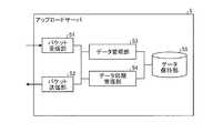
図6は、アップロードサーバの構成の一例を示す図である。アップロードサーバ5は、パケット受信部51、パケット送信部52、データ管理部53、データ同期管理部54、データ保持部55を有する。(Upload server configuration)
FIG. 6 is a diagram illustrating an example of the configuration of the upload server. The upload
パケット受信部51は、受信パケットを、データ管理部53、データ同期管理部54へ入力する。パケット送信部52は、ルータ3、ストレージ6へパケットを送信する。 The packet receiving unit 51 inputs the received packet to the
データ管理部53は、ユーザ端末7からのアップロードデータをデータ保持部55に一時保存するとともに、一時保存情報をデータ保持部55に格納して管理する。一時保存情報は、図7に示すテーブル55aに示すとおりである。テーブル55aは、「送信元IPアドレス」、「ユーザ識別子」、「ファイル名」のカラムを含む。 The
図7に示すテーブル55aは、例えば、「送信元IPアドレス」“xxx.xxx.xxx.xxx”であるユーザ端末7、「ユーザ識別子」“123456”であるユーザ端末7のユーザ、「ファイル名」“XYZ”のアップロードデータが、データ保持部55に一時保存されていることを示す。また、図7に示すテーブル55aは、例えば、「送信元IPアドレス」“yyy.yyy.yyy.yyy”であるユーザ端末7、「ユーザ識別子」“456789”であるユーザ端末7のユーザ、「ファイル名」“YYY”のアップロードデータが、データ保持部55に一時保存されていることを示す。 The table 55a illustrated in FIG. 7 includes, for example, the
また、データ管理部53は、データ保持部55にアップロードデータが一時保存されていることを示すデータ配備フラグを、HTTP等のプロトコルにてストレージ6へ通知する。 In addition, the
データ同期管理部54は、ポリシー制御サーバ4からの同期指示を受信すると、同期指示が指定する、データ保持部55に一時保存されているアップロードデータである同期データを、FTP(File Transfer Protocol)、HTTP等のプロトコルによりストレージ6へ送信する、アップロードデータ同期処理を行う。 When receiving the synchronization instruction from the
(ストレージの構成)
図8は、ストレージの構成の一例を示す図である。ストレージ6は、パケット受信部61、パケット送信部62、データ管理部63、アップロード配備状況管理部64、データ保持部65を有する。(Storage configuration)
FIG. 8 is a diagram illustrating an example of a storage configuration. The
パケット受信部61は、受信パケットを、データ管理部63、アップロード配備状況管理部64へ入力する。パケット送信部62は、ルータ3、アップロードサーバ5へパケットを送信する。 The packet receiving unit 61 inputs the received packet to the
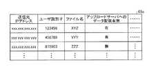
データ管理部63は、ユーザ端末7からのアップロードデータ、アップロードサーバ5からの同期データをデータ保持部65に保存するとともに、保存情報をデータ保持部65に格納して管理する。保存情報は、図9に示すテーブル65aに示すとおりである。テーブル65aは、「送信元IPアドレス」、「ユーザ識別子」、「ファイル名」、「アップロードサーバへのデータ配備有無」のカラムを含む。 The
図9に示すテーブル65aは、例えば、「送信元IPアドレス」“xxx.xxx.xxx.xxx”であるユーザ端末7、「ユーザ識別子」“123456”であるユーザ端末7のユーザ、「ファイル名」“XYZ”のアップロードデータが、ストレージ6のデータ保持部65に保存されていることを示す。また、図9に示すテーブル65aは、例えば、「送信元IPアドレス」“yyy.yyy.yyy.yyy”であるユーザ端末7、「ユーザ識別子」“456789”であるユーザ端末7のユーザ、「ファイル名」“YYY”のアップロードデータが、ストレージ6のデータ保持部65に保存されていることを示す。 The table 65a shown in FIG. 9 includes, for example, the
なお、図9に示す、「送信元IPアドレス」“xxx.xxx.xxx.xxx”、「ユーザ識別子」“123456”、「ファイル名」“XYZ”と、「送信元IPアドレス」“yyy.yyy.yyy.yyy”、「ユーザ識別子」“456789”、「ファイル名」“YYY”の2つのアップロードデータは、同期データの同期処理を経てストレージ6のデータ保持部65に保存される。そして、この2つのアップロードデータは、同期データの同期処理後、一定期間経過後にアップロードサーバ5から削除された際に、テーブル65aの「アップロードサーバへのデータ配備有無」が“無”となる。 9, “source IP address” “xxx.xxx.xxx.xxx”, “user identifier” “123456”, “file name” “XYZ”, and “source IP address” “yyy.yyy”. Two upload data of “.yyy.yyy”, “user identifier” “456789”, and “file name” “YYY” are stored in the
また、図9に示すテーブル65aは、例えば、「送信元IPアドレス」“zzz.zzz.zzz.zzz”であるユーザ端末7、「ユーザ識別子」“875903”であるユーザ端末7のユーザ、「ファイル名」“ZZZ”のアップロードデータが、ストレージ6のデータ保持部65に保存されているが、アップロードサーバ5のデータ保持部55には一時保存されていないことを示す。このアップロードデータは、アップロードサーバ5のデータ保持部55に一時保存されていたが、同期データの同期処理後、一定期間経過後にアップロードサーバ5から削除されたために、テーブル65aの「アップロードサーバへのデータ配備有無」が“無”となっている。 Further, the table 65a shown in FIG. 9 includes, for example, the
アップロード配備状況管理部64は、アップロードサーバ5からのデータ配備フラグの通知に応じて、アップロードサーバ6にアップロードデータが配備されているかを、該当アップロードデータに対応するテーブル65aの「アップロードサーバへのデータ配備有無」にて管理する。 In response to the notification of the data deployment flag from the upload
(ネットワーク入口のルータの処理)
図10は、ネットワーク入口のルータの処理の一例を示すフローチャートである。ネットワーク入口のルータとは、図1に示すルータ3−1である。先ず、ルータ3−1は、ストレージ6のIPアドレス及び当該ストレージ6へのアップロード要求をポリシー制御サーバ4へ転送するか否かの情報を、ストレージ6毎に受信する(ステップS301)。ルータ3−1は、ステップS301で受信した情報を自装置へ設定する(ステップS302)。(Router processing at the network entrance)
FIG. 10 is a flowchart illustrating an example of processing of the router at the network entrance. The router at the network entrance is the router 3-1 shown in FIG. First, the router 3-1 receives, for each
次に、ルータ3−1は、ユーザ端末からパケットを受信する(ステップS303)。次に、ルータ3−1は、ステップS303で受信したパケットから送信先IPアドレスを取得する(ステップS304)。次に、ルータ3−1は、テーブル36aを参照し、ステップS304で取得したパケットの送信先IPアドレスが、ポリシー制御サーバ4への転送有に該当するストレージ6へのアクセスであるか否かを判定する(ステップS305)。ルータ3−1は、該当ストレージ6へのアクセスであると判定した場合(ステップS305Yes)、ステップS306へ処理を移す。一方、ルータ3−1は、該当ストレージ6へのアクセスでないと判定した場合(ステップS305No)、ステップS311へ処理を移す。 Next, the router 3-1 receives a packet from the user terminal (step S303). Next, the router 3-1 acquires the transmission destination IP address from the packet received in step S303 (step S304). Next, the router 3-1 refers to the table 36 a and determines whether or not the transmission destination IP address of the packet acquired in step S <b> 304 is access to the
ステップS306では、ルータ3−1は、ステップS303で受信したパケットのデータをポリシー制御サーバ4へ転送する。次に、ルータ3−1は、ステップS306で送信したパケットのデータに対するポリシー制御サーバ4からの応答を受信する(ステップS307)。次に、ルータ3−1は、ステップS307で受信したポリシー制御サーバ4からの応答におけるアップロードサーバ5への転送フラグの有無を判定する(ステップS308)。ルータ3−1は、ステップS307で受信したポリシー制御サーバ4からの応答においてアップロードサーバ5への転送フラグ有と判定した場合(ステップS308Yes)、ステップS309へ処理を移す。一方、ルータ3−1は、ステップS307で受信したポリシー制御サーバ4からの応答においてアップロードサーバ5への転送フラグ無と判定した場合(ステップS308No)、ステップS310へ処理を移す。 In step S306, the router 3-1 transfers the data of the packet received in step S303 to the
ステップS309では、ルータ3−1は、ステップS303で受信したパケットをアップロードサーバ5へ転送する。また、ステップS310では、ルータ3−1は、ステップS303で受信したパケットをストレージ6へ送信する。他方、ステップS311では、ルータ3−1は、ステップS303で受信したパケットを、ステップS304で取得したパケットの送信先IPアドレスに基づいて転送する。ステップS309〜S311の処理が終了すると、ルータ3−1は、ネットワーク入口のルータの処理を終了する。 In step S309, the router 3-1 transfers the packet received in step S303 to the upload
(ネットワーク出口のルータの処理)
図11は、ネットワーク出口のルータの処理の一例を示すフローチャートである。ネットワーク出口のルータとは、図1に示すルータ3−2である。先ず、ルータ3−2は、パケットを受信する(ステップS321)。次に、ルータ3−2は、ステップS321で受信したパケットの送信先IPアドレス、送信元IPアドレス、データサイズの情報を取得する(ステップS322)。(Network exit router processing)
FIG. 11 is a flowchart illustrating an example of processing of the router at the network exit. The router at the network exit is the router 3-2 shown in FIG. First, the router 3-2 receives a packet (step S321). Next, the router 3-2 acquires information on the transmission destination IP address, the transmission source IP address, and the data size of the packet received in step S321 (step S322).
次に、ルータ3−2は、ステップS321で受信したパケットをストレージ6へ転送する(ステップS323)。次に、ルータ3−2は、自装置への同時接続数、自装置の空き帯域を計算する(ステップS324)。次に、ルータ3−2は、計測した自装置への同時接続数、自装置の空き帯域を、ポリシー制御サーバ4へ一定時間毎に送信する(ステップS325)。ステップS325の処理が終了すると、ルータ3−2は、ネットワーク出口のルータの処理を終了する。 Next, the router 3-2 transfers the packet received in step S321 to the storage 6 (step S323). Next, the router 3-2 calculates the number of simultaneous connections to the own device and the free bandwidth of the own device (step S324). Next, the router 3-2 transmits the measured number of simultaneous connections to the own device and the available bandwidth of the own device to the
(ポリシー制御サーバの転送判定処理)
図12は、ポリシー制御サーバの転送判定処理の一例を示すフローチャートである。先ず、ポリシー制御サーバ4は、ネットワーク出口のルータ3−2から、同時接続数、空き帯域の情報を受信する(ステップS401)。次に、ポリシー制御サーバ4は、受信した同時接続数、空き帯域の情報で、テーブル45aの更新を行う(ステップS402)。(Policy control server forwarding decision processing)
FIG. 12 is a flowchart illustrating an example of a transfer determination process of the policy control server. First, the
次に、ポリシー制御サーバ4は、ネットワーク入口のルータ3−1からアップロードサーバへの転送問合わせを受信する(ステップS403)。次に、ポリシー制御サーバ4は、ネットワーク出口のルータ3−2の同時接続数、空き帯域状況からネットワークの負荷が閾値より大であるか否かを判定する(ステップS404)。ポリシー制御サーバ4は、ネットワークの負荷が閾値より大であると判定した場合(ステップS404Yes)、ステップS405へ処理を移す。一方、ポリシー制御サーバ4は、ネットワークの負荷が閾値以下であると判定した場合(ステップS404No)、ステップS406へ処理を移す。 Next, the
ステップS405では、ポリシー制御サーバ4は、アップロードサーバ5への転送フラグに転送有を設定し、ルータ3−1へ送信する。一方、ステップS406では、ポリシー制御サーバ4は、アップロードサーバ5への転送フラグに転送無を設定し、ルータ3−1へ送信する。ステップS405、S406の処理が終了すると、ポリシー制御サーバ4は、ポリシー制御サーバの転送判定処理を終了する。 In step S <b> 405, the
(ポリシー制御サーバの同期判定処理)
図13は、ポリシー制御サーバの同期判定処理の一例を示すフローチャートである。先ず、ポリシー制御サーバ4は、ネットワーク出口のルータ3−2から、同時接続数、空き帯域の情報を受信する(ステップS411)。次に、ポリシー制御サーバ4は、受信した同時接続数、空き帯域の情報で、テーブル45aの更新を行う(ステップS412)。次に、ポリシー制御サーバ4は、ネットワーク出口のルータ3−2の同時接続数、空き帯域状況からネットワークの負荷が閾値より大であるか否かを判定する(ステップS413)。ポリシー制御サーバ4は、ネットワークの負荷が閾値より大であると判定した場合(ステップS413Yes)、ポリシー制御サーバの同期判定処理を終了する。一方、ポリシー制御サーバ4は、ネットワークの負荷が閾値以下であると判定した場合(ステップS413No)、アップロードサーバ5とストレージ6の同期と判定し、アップロードサーバ5へストレージ6とのデータの同期指示を送信する(ステップS414)。ステップS414の処理が終了すると、ポリシー制御サーバ4は、ポリシー制御サーバの同期判定処理を終了する。(Policy control server synchronization judgment processing)
FIG. 13 is a flowchart illustrating an example of the synchronization determination process of the policy control server. First, the
(アップロードサーバの処理)
図14は、アップロードサーバの処理の一例を示すフローチャートである。先ず、アップロードサーバ5は、パケットを受信する(ステップS501)。次に、アップロードサーバ5は、ステップS501で受信したパケットが、“アップロード”、“データ同期”、“ダウンロード”のいずれであるかを判定する(ステップS502)。(Upload server processing)
FIG. 14 is a flowchart illustrating an example of processing performed by the upload server. First, the upload
アップロードサーバ5は、ステップS502の判定結果が“アップロード”である場合に、ステップS503へ処理を移す。他方、アップロードサーバ5は、ステップS502の判定結果が“データ同期”である場合に、ステップS505へ処理を移す。他方、アップロードサーバ5は、ステップS502の判定結果が“ダウンロード”である場合に、ステップS508へ処理を移す。 When the determination result in step S502 is “Upload”, the upload
ステップS503では、アップロードサーバ5は、ステップS501で受信したパケットのデータを、データ保持部55へ一時保存し、一時保存情報をテーブル55aに格納する。次に、アップロードサーバ5は、データ配備フラグ、送信元IPアドレス、ユーザ識別子、ファイル名等をストレージ6へ通知する(ステップS504)。ステップS504の処理が終了すると、アップロードサーバ5は、アップロードサーバの処理を終了する。 In step S503, the upload
他方、ステップS505では、アップロードサーバ5は、ステップS501で受信したパケットが同期指示する該当データを、データ保持部55から抽出する。次に、アップロードサーバ5は、ステップS505で抽出したデータを、ストレージ6との間で同期させる(ステップS506)。次に、アップロードサーバ5は、ステップS506でストレージ6との間で同期させたデータを、必要に応じてデータ保持部55から削除する(ステップS507)。ステップS507の処理が終了すると、アップロードサーバ5は、アップロードサーバの処理を終了する。 On the other hand, in step S505, the upload
なお、データ保持部55からアップロードデータを削除する際には、アップロードサーバ5は、削除の旨をストレージ6へ通知する。ストレージ6は、アップロードサーバ5から削除の旨の通知を受けたアップロードデータについて、テーブル65aの該当するレコードの「アップロードサーバへのデータ配備有無」を“無”へと更新する。また、ステップS507でいう“必要に応じてデータを削除”とは、一例として、“データ同期後、一定時間経過するとデータを削除”、“ユーザ毎にFIFO、LRU等のアルゴリズムにより管理されるデータを削除”等が挙げられる。 When deleting the upload data from the
他方、ステップS508では、アップロードサーバ5は、ステップS501で受信したパケットがダウンロード指示する該当データを、データ保持部55から抽出する。次に、アップロードサーバ5は、ステップS508で抽出したデータを、ダウンロードを要求したユーザ端末7が接続されるルータ3−1へ送信する(ステップS509)。ステップS509の処理が終了すると、アップロードサーバ5は、アップロードサーバの処理を終了する。 On the other hand, in step S <b> 508, the upload
(ストレージの処理)
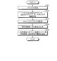
図15は、ストレージの処理の一例を示すフローチャートである。先ず、ストレージ6は、パケットを受信する(ステップS601)。次に、ストレージ6は、ステップS601で受信したパケットが示す指示が“アップロード又はデータ同期”、“アップロードサーバへのデータ配備完了”、“ダウンロード”のいずれであるかを判定する(ステップS602)。ストレージ6は、ステップS601で受信したパケットが示す指示が“アップロード又はデータ同期”である場合、ステップS603へ処理を移す。他方、ストレージ6は、ステップS601で受信したパケットが示す指示が“アップロードサーバへのデータ配備完了”である場合、ステップS606へ処理を移す。他方、ストレージ6は、ステップS601で受信したパケットが示す指示が“ダウンロード”である場合、ステップS607へ処理を移す。(Storage processing)
FIG. 15 is a flowchart illustrating an example of storage processing. First, the
ステップS603では、ストレージ6は、ステップS601で受信したパケットのデータを、データ保持部65へ保存し、保存情報をテーブル65aに格納する。次に、ストレージ6は、ステップS601で受信したパケットが示す指示が“データ同期”であるか否かを判定する(ステップS604)。ストレージ6は、ステップS601で受信したパケットが示す指示が“データ同期”であると判定した場合(ステップS604Yes)、テーブル65aの該当データに対応する「アップロードサーバへのデータ配備有無」を“無”へ更新し(ステップS605)、ストレージの処理を終了する。一方、ストレージ6は、ステップS601で受信したパケットが示す指示が“アップロード”であると判定した場合(ステップS604No)、ストレージの処理を終了する。 In step S603, the
他方、ステップS606では、ストレージ6は、ステップS601で受信したパケットが示す指示が“アップロードサーバへのデータ配備完了”であると判定した場合、ステップS601で受信したパケットのデータに該当するデータ配備フラグ、送信元IPアドレス、ユーザ識別子、ファイル名等をデータ保持部65のテーブル65aに格納する(ステップS606)。ステップS606が終了すると、ストレージ6は、ストレージの処理を終了する。 On the other hand, in step S606, if the
他方、ステップS607では、ストレージ6は、テーブル65aを参照し、ステップS601で受信したパケットがダウンロードを指示するデータがアップロードサーバ5へ配備有か否かを判定する。ストレージ6は、ステップS601で受信したパケットがダウンロードを指示するデータがアップロードサーバ5へ配備有であると判定した場合(ステップS607Yes)、アップロードサーバ5に対して、ダウンロード要求元のユーザ端末7への該当データのダウンロードを指示し(ステップS608)、ストレージの処理を終了する。一方、ストレージ6は、ステップS601で受信したパケットがダウンロードを指示するデータがアップロードサーバ5へ配備無であると判定した場合(ステップS607No)、データ保持部65から該当データを読み出して、ダウンロード要求元のユーザ端末7へダウンロードし(ステップS609)、ストレージの処理を終了する。 On the other hand, in step S607, the
[実施形態による効果]
実施形態は、ポリシー制御サーバが、ネットワークに配備されているルータ、アップロードサーバを一元的に管理し、ネットワークの利用の情報を基に、アップロードサーバの利用有無を決定する。また、実施形態は、ストレージが、アップロードサーバにデータが配備されている状況においては、アップロードサーバからユーザ端末7へデータをダウンロードさせる。また、実施形態は、アップロードサーバ及びストレージが、ネットワークの利用状況から、ネットワークの負荷の少ない時間帯にアップロードサーバからストレージへデータの同期行う。以下、図16A〜図18を用いて、実施形態の各効果について説明する。[Effects of the embodiment]
In the embodiment, the policy control server centrally manages routers and upload servers deployed in the network, and determines whether to use the upload server based on network usage information. In the embodiment, the storage causes the upload server to download data to the
(ストレージシステムにおけるアップロード時の処理概要及び効果)
図16A及び図16Bは、ストレージシステムにおけるアップロード時の処理概要及び効果の一例を説明する図である。図16Aに示すように、(1−1)ネットワーク入口のルータ3−1は、ユーザ端末7からデータのアップロード要求を受信する。(1−2)ルータ3−1は、アップロードの送信先がポリシー制御サーバ4への問合せ対象であった場合には、ポリシー制御サーバ4へ、アップロードサーバ5にデータを転送する否かを問い合わせる。この時のプロトコルはDAIMETER等の認証プロトコルを利用する。(Outline of processing and effects when uploading in a storage system)
FIG. 16A and FIG. 16B are diagrams for explaining an example of processing outline and effects at the time of upload in the storage system. As shown in FIG. 16A, (1-1) the router 3-1 at the network entrance receives a data upload request from the
(1−3)ポリシー制御サーバ4は、事前に入手しているネットワーク出口のルータ3−2の同時接続数、空き帯域からアップロードサーバ5への転送要否を判定し、(1−4)アップロードサーバ5を利用しない旨を、転送フラグを転送無しとして、ルータ3−1へ通知する。(1−5)ルータ3−1は、ポリシー制御サーバ4からの転送フラグをもとに、ストレージ6へアップロードデータを送信する。この時のプロトコルは、認証プロトコルのDIAMETERのAVPに転送フラグを新規付与して実現可能できる。 (1-3) The
また、図16Bに示すように、(2−1)ルータ3−1は、ユーザ端末7からデータのアップロード要求を受信する。(2−2)ルータ3−1は、アップロードの送信先がポリシー制御サーバ4への問合せ対象であった場合には、ポリシー制御サーバ4へ、アップロードサーバにデータを転送する否かを問い合わせる。 Also, as shown in FIG. 16B, (2-1) the router 3-1 receives a data upload request from the
(2−3)ポリシー制御サーバ4は、事前に入手しているネットワーク出口のルータ3−2の同時接続数、空き帯域からアップロードサーバ5への転送要否を判定し、(2−4)アップロードサーバ5を利用する旨を、転送フラグを転送有りとして、ルータ3−1へ通知する。(2−5)ルータ3−1は、ポリシー制御サーバ4からの転送フラグをもとに、アップロードサーバ5へアップロードデータを転送する。この時のプロトコルは、認証プロトコルのDIAMETERのAVPに転送フラグを新規付与して実現可能できる。 (2-3) The
(2−6)アップロードサーバ5は、アップロードデータを一時保存し、送信元IPアドレス、ユーザ識別子、ファイル名、データ配備フラグ等をストレージ6へ通知する。この時のプロトコルはHTTPを利用し、データ配備フラグ、送信元IPアドレス、ユーザ識別子、ファイル名は、HTTPのボディ部に新規付与して実現可能である。これにより、ストレージ6は、少なくともアップロードサーバ5には、該当データが一時保存されていることを認識でき、また、ユーザ端末7に対して、あたかもストレージ6にアップロードデータがアップロードされているように見せることができ、アップロードサーバ5へ一時保存されているアップロードデータをダウンロードさせることにより、ユーザ端末7からのダウンロード要求にも対応することができる。 (2-6) The upload
よって、実施形態によれば、ポリシー制御サーバ4が、ネットワーク2の同時接続数や空き帯域の状況に応じて、ストレージ6へのアップロードデータを、アップロードサーバ5へ一時保存させることで、ネットワーク2の負荷及びストレージ6の負荷増大を回避しつつ、スムーズなアップロードを実現できる。 Therefore, according to the embodiment, the
(ストレージシステムにおけるダウンロード時の処理概要及び効果)
図17は、ストレージシステムにおけるダウンロード時の処理概要及び効果の一例を説明する図である。図17に示すように、(3−1)ユーザ端末7からストレージ6へ、データのダウンロードが要求される。(3−2)ストレージ6は、ダウンロード要求されたデータがアップロードサーバ5にデータ配備されているかを確認し、アップロードサーバへの接続判断を行う。(3−3)ストレージ6は、ストレージ6にデータが配備されている場合には、ストレージ6からデータをダウンロードさせる。(3−4)一方、ストレージ6は、ストレージ6にデータが配備されていない場合には、ユーザ端末7に対してアップロードサーバ5のIPアドレス等の接続情報を示し、アップロードサーバ5からダウンロードを実行するよう指示する。(3−5)ユーザ端末7は、ストレージ6から取得したアップロードサーバ5の接続情報をもとに、アップロードサーバ5へ接続し、ダウンロードを要求し、(3−6)データを取得する。(Outline of processing and effects when downloading in a storage system)
FIG. 17 is a diagram for explaining an example of processing outline and effects at the time of downloading in the storage system. As shown in FIG. 17, (3-1) data download is requested from the
よって、実施形態によれば、アップロードサーバ5にアップロードデータが一時保存され、ストレージ6にはアップロードデータが配備されていない状況であっても、ユーザは、当該データをダウンロードできる。 Therefore, according to the embodiment, even when upload data is temporarily stored in the upload
(ストレージシステムにおける同期処理)
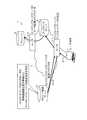
図18は、ストレージシステムにおける同期処理の概要及び効果の一例を説明する図である。(4−1)ネットワーク出口のルータ3−2は、定期的に自装置の同時接続数と空き帯域をポリシー制御サーバ4へ送信する。(4−2)ポリシー制御サーバ4は、ネットワーク出口のルータ3−2から同時接続数と空き帯域の情報を受信し、テーブル45aを更新する。(4−3)ポリシー制御サーバ4は、同時接続数と空き帯域からネットワークの負荷に余裕があると判定すると、アップロードサーバ5へデータの同期指示を送信する。(4−4)アップロードサーバ5は、ポリシー制御サーバ4からのデータ同期指示をもとに、ストレージ6との間でデータの同期を行う。このときのデータ同期に利用するプロトコルはFTP、HTTP等を利用する。(Synchronous processing in the storage system)
FIG. 18 is a diagram for explaining an example of the outline and effects of the synchronization processing in the storage system. (4-1) The router 3-2 at the network exit periodically transmits the number of simultaneous connections of the own device and the free bandwidth to the
よって、実施形態によれば、ネットワーク2の利用状況からネットワーク2の負荷の少ない時にアップロードサーバ5からストレージ6へデータの同期を行うことで、ネットワーク2の負荷及びストレージ6の負荷を増大させることなく、アップロードサーバ5へ一時保存したアップロードデータを、アップロードサーバ5からストレージ6へアップロードすることができる。 Therefore, according to the embodiment, by synchronizing the data from the upload
すなわち、実施形態は、ネットワークに配備されているアップロードサーバ、ルータを一元的に管理し、ルータの同時接続数や帯域等からネットワークの負荷情報を収集し、ネットワーク帯域の負荷が高い時には、アップロードデータのアップロード時にアップロードサーバを利用することで、ネットワークの上位レイヤの負荷を低減できる。また、実施形態は、ストレージへのアクセスを分散させられるため、ストレージの負荷を低減できる。 In other words, the embodiment centrally manages upload servers and routers deployed in the network, collects network load information from the number of simultaneous connections and bandwidths of routers, and uploads data when the load on the network bandwidth is high. By using an upload server when uploading, the load on the upper layer of the network can be reduced. In addition, since the access to the storage can be distributed in the embodiment, the load on the storage can be reduced.
[その他の実施形態]
実施形態は、送信元及び送信先のアドレス情報として、IPアドレスを用いる例を示したが、IPアドレス及びMAC(Media Access Control)アドレスを併用してもよい。また、実施形態は、ストレージは、ユーザからのダウンロード要求に対して、自装置が該当データを保持する場合には、自装置から該当データをダウンロードさせ、自装置が該当データを保持しない場合に、アップロードサーバから該当データをダウンロードさせるとした。しかし、これに限らず、アップロードサーバが該当データを保持する場合には、ストレージが該当データを保持するか否かに関わらず、アップロードサーバから該当データをダウンロードさせるとしてもよい。これにより、ダウンロードの際にもアップロードサーバをキャッシュサーバとして用いることができ、ダウンロードの際のネットワーク及びストレージの負荷を分散させることができる。[Other Embodiments]
In the embodiment, the IP address is used as the address information of the transmission source and the transmission destination. However, the IP address and the MAC (Media Access Control) address may be used in combination. In the embodiment, in response to a download request from the user, when the own device holds the corresponding data, the storage downloads the corresponding data from the own device, and when the own device does not hold the corresponding data, The corresponding data is downloaded from the upload server. However, the present invention is not limited thereto, and when the upload server holds the corresponding data, the corresponding data may be downloaded from the upload server regardless of whether the storage holds the corresponding data. As a result, the upload server can be used as a cache server during download, and the network and storage loads during download can be distributed.
また、その他の実施形態として、ポリシー制御サーバは、アップロードサーバのトラヒックも監視し、ストレージのトラヒックと比較して、いずれかトラヒックが少ない方へアップロードデータを送信させてもよい。 As another embodiment, the policy control server may monitor the traffic of the upload server, and may transmit the upload data to one with less traffic compared to the storage traffic.
[ルータ、ポリシー制御サーバ、アップロードサーバ、ストレージの装置構成について]
図2に示すルータ3、図4に示すポリシー制御サーバ4、図6に示すアップロードサーバ5、図8に示すストレージ6の各構成要素は機能概念的なものであり、必ずしも物理的に図示のように構成されていることを要しない。すなわち、ルータ3、ポリシー制御サーバ4、アップロードサーバ5、ストレージ6の機能の分散及び統合の具体的形態は図示のものに限られず、全部又は一部を、各種の負荷や使用状況等に応じて、任意の単位で機能的又は物理的に分散又は統合して構成することができる。例えば、ルータ3の空き帯域計測をポリシー制御サーバ4で実施してもよい。[Router, policy control server, upload server, storage device configuration]
Each component of the
また、ルータ3、ポリシー制御サーバ4、アップロードサーバ5、ストレージ6において行われる各処理は、全部又は任意の一部が、CPU(Central Processing Unit)もしくはNP(Network Processor)ならびにCPUもしくはNPにより解析実行されるプログラムにて実現されてもよい。また、ルータ3、ポリシー制御サーバ4、アップロードサーバ5、ストレージ6において行われる各処理は、ワイヤードロジックによるハードウェアとして実現されてもよい。 In addition, all or any part of each process performed in the
また、実施形態において説明した各処理のうち、自動的に行われるものとして説明した処理の全部又は一部を手動的に行うこともできる。もしくは、実施形態において説明した各処理のうち、手動的に行われるものとして説明した処理の全部又は一部を公知の方法で自動的に行うこともできる。この他、上述及び図示の処理手順、制御手順、具体的名称、各種のデータやパラメータを含む情報については、特記する場合を除いて適宜変更することができる。 In addition, among the processes described in the embodiment, all or a part of the processes described as being automatically performed can be manually performed. Alternatively, all or some of the processes described as being manually performed among the processes described in the embodiments can be automatically performed by a known method. In addition, the above-described and illustrated processing procedures, control procedures, specific names, and information including various data and parameters can be changed as appropriate unless otherwise specified.
[プログラムについて]
図19は、プログラムが実行されることにより、ルータ、ポリシー制御サーバ、アップロードサーバ、ストレージが実現されるコンピュータの一例を示す図である。コンピュータ1000は、例えば、メモリ1010、CPU(もしくはNP)1020を有する。また、コンピュータ1000は、ハードディスクドライブインタフェース1030、ディスクドライブインタフェース1040、シリアルポートインタフェース1050、ビデオアダプタ1060、ネットワークインタフェース1070を有する。コンピュータ1000において、これらの各部はバス1080によって接続される。[About the program]
FIG. 19 is a diagram illustrating an example of a computer that realizes a router, a policy control server, an upload server, and a storage by executing a program. The
メモリ1010は、ROM(Read Only Memory)1011及びRAM(Random Access Memory)1012を含む。ROM1011は、例えば、BIOS(Basic Input Output System)等のブートプログラムを記憶する。ハードディスクドライブインタフェース1030は、ハードディスクドライブ1031に接続される。ディスクドライブインタフェース1040は、ディスクドライブ1041に接続される。例えば磁気ディスクや光ディスク等の着脱可能な記憶媒体が、ディスクドライブ1041に挿入される。シリアルポートインタフェース1050は、例えばマウス1051、キーボード1052に接続される。ビデオアダプタ1060は、例えばディスプレイ1061に接続される。 The
ハードディスクドライブ1031は、例えば、OS1091、アプリケーションプログラム1092、プログラムモジュール1093、プログラムデータ1094を記憶する。すなわち、ルータ3、ポリシー制御サーバ4、アップロードサーバ5、ストレージ6の各処理を規定するプログラムは、コンピュータ1000によって実行される指令が記述されたプログラムモジュール1093として、例えばハードディスクドライブ1031に記憶される。例えば、ルータ3、ポリシー制御サーバ4、アップロードサーバ5、ストレージ6における機能構成と同様の情報処理を実行するためのプログラムモジュール1093が、ハードディスクドライブ1031に記憶される。 The hard disk drive 1031 stores, for example, an
また、実施形態の処理で用いられる設定データは、プログラムデータ1094として、例えばメモリ1010やハードディスクドライブ1031に記憶される。そして、CPU1020が、メモリ1010やハードディスクドライブ1031に記憶されたプログラムモジュール1093やプログラムデータ1094を必要に応じてRAM1012に読み出して実行する。 The setting data used in the processing of the embodiment is stored as
なお、プログラムモジュール1093やプログラムデータ1094は、ハードディスクドライブ1031に記憶される場合に限らず、例えば着脱可能な記憶媒体に記憶され、ディスクドライブ1041等を介してCPU1020によって読み出されてもよい。あるいは、プログラムモジュール1093やプログラムデータ1094は、ネットワーク(LAN(Local Area Network)、WAN(Wide Area Network)等)を介して接続された他のコンピュータに記憶されてもよい。そして、プログラムモジュール1093やプログラムデータ1094は、ネットワークインタフェース1070を介してCPU1020によって読み出されてもよい。 Note that the
上記実施形態及びその他の実施形態は、本願が開示する技術に含まれると同様に、特許請求の範囲に記載された発明とその均等の範囲に含まれるものである。 The above-described embodiments and other embodiments are included in the invention disclosed in the claims and equivalents thereof as well as included in the technology disclosed in the present application.
1 アップロードシステム
2 ネットワーク
3、3−1、3−2 ルータ
31 パケット受信部
32 パケット送信部
33 転送判定部
34 同時接続数計測部
35 空き帯域計測部
36 テーブル保持部
36a テーブル
4 ポリシー制御サーバ
41 パケット受信部
42 パケット送信部
43 転送判定部
44 同期タイミング制御部
45 テーブル保持部
45a テーブル
5 アップロードサーバ
51 パケット受信部
52 パケット送信部
53 データ管理部
54 データ同期管理部
55 データ保持部
55a テーブル
6 ストレージ
61 パケット受信部
62 パケット送信部
63 データ管理部
64 アップロード配備状況管理部
65 データ保持部
65a テーブル
7 ユーザ端末
1000 コンピュータ
1010 メモリ
1020 CPUDESCRIPTION OF
Claims (5)
Translated fromJapaneseアップロードデータを一時格納するデータ一時格納装置と、
ユーザ端末からのアップロードデータを転送する第1の転送装置と、
前記第1の転送装置から転送された前記データ格納装置宛のアップロードデータを前記データ格納装置へ転送する第2の転送装置と、
前記第2の転送装置におけるネットワーク負荷が閾値を越える場合に、前記ユーザ端末から前記データ格納装置宛のアップロードデータを前記データ一時格納装置宛へ転送し、該ネットワーク負荷が閾値を越えない場合に、該アップロードデータを前記データ格納装置宛として前記第2の転送装置へ転送するよう前記第1の転送装置を制御する管理装置と
を備えることを特徴とするアップロードシステム。A data storage device for storing upload data;
A temporary data storage device for temporarily storing upload data;
A first transfer device for transferring upload data from the user terminal;
A second transfer device for transferring the upload data addressed to the data storage device transferred from the first transfer device to the data storage device;
When the network load in the second transfer device exceeds a threshold, the upload data addressed to the data storage device is transferred from the user terminal to the data temporary storage device, and when the network load does not exceed the threshold, An upload system comprising: a management device that controls the first transfer device to transfer the upload data to the second transfer device as the data storage device.
ことを特徴とする請求項1に記載のアップロードシステム。The management device is a case where the temporary data storage device temporarily stores upload data to be stored in the data storage device, and when the network load in the second transfer device does not exceed a threshold value, The upload system according to claim 1, wherein the data temporary storage device is controlled to synchronize the upload data between the data temporary storage device and the data storage device.
前記管理装置は、前記第1の転送装置から転送されたアップロードデータについて、前記ネットワーク負荷が前記閾値を越える場合に、該アップロードデータを前記データ一時格納装置宛へ転送し、該ネットワーク負荷が該閾値を越えない場合に、該アップロードデータを前記データ格納装置宛として前記第2の転送装置へ転送するよう前記第1の転送装置を制御する
ことを特徴とする請求項1又は2に記載のアップロードシステム。The first transfer device transfers the upload data to the management device when the upload data addressed to the data storage device from the user terminal matches a transfer condition for transfer to the management device, and the upload data is If the transfer conditions are not met, the upload data is transferred to the data storage device,
When the network load exceeds the threshold value for the upload data transferred from the first transfer device, the management device transfers the upload data to the data temporary storage device, and the network load is set to the threshold value. 3. The upload system according to claim 1, wherein the first transfer device is controlled so as to transfer the upload data to the second transfer device as if it is addressed to the data storage device if not exceeding .
前記データ格納装置は、ユーザ端末からのデータのダウンロード要求に対して、該データが前記データ一時格納装置に一時格納されている場合には、該データを前記データ一時格納装置からダウンロードするよう該ユーザ端末に対して通知する
ことを特徴とする請求項1、2又は3に記載のアップロードシステム。The data temporary storage device notifies the data storage device that the upload data is temporarily stored,
In response to a data download request from a user terminal, the data storage device is configured to download the data from the temporary data storage device when the data is temporarily stored in the temporary data storage device. The upload system according to claim 1, 2 or 3, wherein notification is made to the terminal.
前記アップロードシステムは、
アップロードデータを格納するデータ格納装置と、
アップロードデータを一時格納するデータ一時格納装置と、
ユーザ端末からのアップロードデータを転送する第1の転送装置と、
前記第1の転送装置から転送された前記データ格納装置宛のアップロードデータを前記データ格納装置へ転送する第2の転送装置と、
管理装置と
を備え、
前記管理装置が、前記第2の転送装置におけるネットワーク負荷が閾値を越える場合に、前記ユーザ端末から前記データ格納装置宛のアップロードデータを前記データ一時格納装置宛へ転送し、該ネットワーク負荷が閾値を越えない場合に、該アップロードデータを前記データ格納装置宛として前記第2の転送装置へ転送するよう前記第1の転送装置を制御し、
前記データ一時格納装置が、前記第1の転送装置により前記データ一時格納装置宛へ転送されたアップロードデータを一時格納し、
前記管理装置が、前記データ一時格納装置が前記データ格納装置へ格納される予定のアップロードデータを一時格納している場合であって、前記第2の転送装置におけるネットワーク負荷が閾値を越えない時に、該アップロードデータを前記データ一時格納装置と前記データ格納装置との間で同期するよう前記データ一時格納装置を制御する
ことを含むことを特徴とするアップロード方法。An upload method of upload data executed by the upload system,
The upload system
A data storage device for storing upload data;
A temporary data storage device for temporarily storing upload data;
A first transfer device for transferring upload data from the user terminal;
A second transfer device for transferring the upload data addressed to the data storage device transferred from the first transfer device to the data storage device;
A management device and
When the network load in the second transfer device exceeds a threshold value, the management device transfers upload data addressed to the data storage device from the user terminal to the data temporary storage device, and the network load exceeds the threshold value. If not, controlling the first transfer device to transfer the upload data to the second transfer device addressed to the data storage device;
The data temporary storage device temporarily stores the upload data transferred to the data temporary storage device by the first transfer device;
When the management device temporarily stores the upload data that is to be stored in the data storage device, and the network load on the second transfer device does not exceed a threshold, Controlling the temporary data storage device to synchronize the upload data between the temporary data storage device and the data storage device.
Priority Applications (1)
| Application Number | Priority Date | Filing Date | Title |
|---|---|---|---|
| JP2015024326AJP2016148922A (en) | 2015-02-10 | 2015-02-10 | Upload system and upload method |
Applications Claiming Priority (1)
| Application Number | Priority Date | Filing Date | Title |
|---|---|---|---|
| JP2015024326AJP2016148922A (en) | 2015-02-10 | 2015-02-10 | Upload system and upload method |
Publications (1)
| Publication Number | Publication Date |
|---|---|
| JP2016148922Atrue JP2016148922A (en) | 2016-08-18 |
Family
ID=56688386
Family Applications (1)
| Application Number | Title | Priority Date | Filing Date |
|---|---|---|---|
| JP2015024326APendingJP2016148922A (en) | 2015-02-10 | 2015-02-10 | Upload system and upload method |
Country Status (1)
| Country | Link |
|---|---|
| JP (1) | JP2016148922A (en) |
- 2015
- 2015-02-10JPJP2015024326Apatent/JP2016148922A/enactivePending
Similar Documents
| Publication | Publication Date | Title |
|---|---|---|
| CN108476177B (en) | Apparatus and related method to support data plane for handling functional scalability | |
| US10455046B2 (en) | Choreographed caching | |
| CN109600388B (en) | Data transmission method and device, computer readable medium and electronic equipment | |
| US8261339B2 (en) | Dynamic network tunnel endpoint selection | |
| CN108848530B (en) | Method and device for acquiring network resources and scheduling server | |
| CN107820043B (en) | Control method, device and system for video surveillance system | |
| WO2013152472A1 (en) | Communication method and system, access network device, and application server | |
| CN105264918A (en) | System and method for distributed evolved packet core architecture | |
| JP2014528211A (en) | Mobile communication network, board device and method | |
| CN109842567B (en) | Data distribution method and distribution server | |
| CN103888539B (en) | Bootstrap technique, device and the P2P caching systems of P2P cachings | |
| US10432530B2 (en) | System and method of providing compression technique for jitter sensitive application through multiple network links | |
| WO2017125017A1 (en) | Method for adjusting cache content, device, and system | |
| JP2014531810A (en) | Communication terminal and method | |
| KR20140021371A (en) | Contents delivery service system using contents identification, apparatus therefor and contents delivery service method thereof | |
| WO2012034414A1 (en) | Method and system for processing peer to peer (p2p) services | |
| US11540026B2 (en) | Data relay apparatus, method, delivery system, and program | |
| EP3364610B1 (en) | Method, device and system for deploying service stream forwarding function | |
| CN108111623A (en) | A kind of communication means and device based on content distributing network CDN | |
| JP6500214B2 (en) | Data distribution device and imaging device | |
| US9609684B2 (en) | Apparatus and method for transmitting/receiving data in mobile content network | |
| JP2016148922A (en) | Upload system and upload method | |
| EP2843889A1 (en) | System and method for routing traffic in a mobile network interfaced with a cdn | |
| JP5790399B2 (en) | COMMUNICATION DEVICE, COMMUNICATION METHOD, AND COMMUNICATION PROGRAM | |
| KR101407934B1 (en) | System for distributing a content, method and apparatus thereof |