JP2016140696A - Ligature transporter - Google Patents
Ligature transporterDownload PDFInfo
- Publication number
- JP2016140696A JP2016140696AJP2015021101AJP2015021101AJP2016140696AJP 2016140696 AJP2016140696 AJP 2016140696AJP 2015021101 AJP2015021101 AJP 2015021101AJP 2015021101 AJP2015021101 AJP 2015021101AJP 2016140696 AJP2016140696 AJP 2016140696A
- Authority
- JP
- Japan
- Prior art keywords
- inner tube
- loop wire
- tube
- rod
- transporter
- Prior art date
- Legal status (The legal status is an assumption and is not a legal conclusion. Google has not performed a legal analysis and makes no representation as to the accuracy of the status listed.)
- Granted
Links
Images


Landscapes
- Surgical Instruments (AREA)
Abstract
Description
Translated fromJapanese本発明は、特に小児のヘルニアに対して、腹腔鏡下外科手術によりヘルニア門(腹膜の穴)を結紮閉鎖するさい、該ヘルニア門の一周囲に縫合糸を配置するための結紮糸輸送器に関する。 The present invention relates to a ligature transporter for ligating and closing a hernia gate (peritoneal hole) by laparoscopic surgery, particularly for a pediatric hernia, and for placing a suture around the hernia gate. .
小児の鼠径ヘルニアは、出生する前に閉鎖されるはずの腹膜(腹膜鞘状突起)が開いたままで、そこに腸などの臓器が入り込み鼠径部が膨らんでくる病気で、従来は、鼠径部を1〜2cm切開し、ヘルニアが脱出している袋状のヘルニア嚢を該ヘルニア嚢の根元(ヘルニア門)で結紮して臓器が脱出しないようにする手術が行われてきたが、近年では、創部を小さくすることが可能で、また、従来手術では分らない反対側のヘルニアも確認でき、同時に手術することもできる腹腔鏡下経皮的腹膜外ヘルニア閉鎖術(LPEC法:Laparoscopic Percutaneous Extraperitoneal Closure)が標準術式のひとつとなっている。 A child's inguinal hernia is a disease in which the peritoneum (peritoneal sheath), which should be closed before birth, remains open, and an organ such as the intestines enters into the inguinal region. An operation has been performed in which an incision of 1 to 2 cm is made and a bag-like hernia sac from which the hernia has escaped is ligated at the root (hernia gate) of the hernia sac so that the organ does not escape. Laparoscopic percutaneous extraperitoneal hernia closure (LPEC: Laparoscopy Percutaneous Closure) can be performed, and the contralateral hernia that cannot be confirmed by conventional surgery can be confirmed. One of the standard techniques.
このLPEC法は、臍部に設ける3mm〜5mmの小さな切開創から腹腔鏡を、側腹部から3mmの鉗子を腹腔内に挿入し、鼠径部から穿刺される縫合糸を取り付けた針状の結紮糸輸送器を用いて、挿入した腹腔鏡観察下でヘルニアを起こしている腹膜のヘルニア門を前記縫合糸で一周して結紮閉塞する方法である。(例えば、非特許文献1、2) In this LPEC method, a laparoscope is inserted from a small incision of 3 mm to 5 mm provided in the umbilicus, a 3 mm forceps from the flank is inserted into the abdominal cavity, and a needle-like ligature with a suture thread pierced from the groin is attached. This is a method of ligating and closing the peritoneal hernia gate, which is causing a hernia under the observation of the inserted laparoscope, with the suture thread using the transporter. (For example, Non-Patent
図7は、前記LPEC法に用いる従来の結紮糸輸送器で、刃先51を備えた針管5と、該針管5の内腔に摺動可能に挿入される、弾性を有し展開状態に癖付けされた金属ループワイヤー61を備えたロッド(外管の内腔へ配置)と、針管5の把持部となる針基52、及び、ロッドの把持部となる操作部62より構成され、針基52に対する操作部62の相対的な前後退操作により針管先端51からループワイヤー61が突出した状態(図7B)と、針管5内に収納された状態(図7A)をとり、該ループワイヤー61に縫合糸を通して、ループワイヤー61を針管5内に収納することでループが絞られ、該縫合糸を保持することができる器具となっている。 FIG. 7 shows a conventional ligature transporter used in the LPEC method, and a
前記結紮糸輸送器を使用しての一般的なLPEC法の手順は次の通りである。
1.鼠径部への穿刺の前に、結紮糸輸送器のループワイヤー61に縫合糸を通し、針管5内にループワイヤー61を引き込んで収納し、縫合糸を器具の先端に保持する。
2.輸送器の穿刺部に小切開を置き、切開部に針管を穿刺して、針先51の位置がヘルニア門上縁にあることを確認する。
3.位置が確認できたら、輸送器の先端をヘルニア門上縁から下縁に向かい外側縁(左右どちらか側)に沿って腹膜外を剥離するように運針し、ヘルニア門下縁まで剥離したら針管先端51で腹腔内に穿破する。
4.ここで、ループワイヤー61を針管5から突出させ、縫合糸をループから外し、縫合糸を保持しない状態で再びループワイヤー61を針管5内に収納し、器具の先端部をヘルニア門上縁まで引き戻す。(これまでの操作により縫合糸は、体外からヘルニア門の半周囲を通ってヘルニア門下縁で腹腔内まで通されて配置されており、糸の先端部は腹腔内に残されている。)
5.次に、引き戻された輸送器を、ヘルニア門上縁から下縁に向けて反対側の縁となる内側縁に沿って腹膜外を剥離するように運針し、ヘルニア門下縁の最初に穿破した位置となるべく一致する位置で再び腹腔内に穿破する。
6.ここで、ループワイヤー61を針管から突出させ、腹腔内に残した縫合糸をループワイヤー61内に誘導し、縫合糸を保持した状態でワイヤーループ61を針管5内に引き込んで収納して、その状態で輸送器を引き戻し、小切開部から体外に取り出す。これにより、縫合糸は、体外からヘルニア門一周囲を通して先端が体外から取り出されたことになる。
7.輸送器から縫合糸を外し、体外で縫合糸の両端を結紮することによりヘルニア門が縫縮される。The general LPEC procedure using the ligature transporter is as follows.
1. Prior to puncturing the groin, the suture is passed through the
2. Place a small incision in the puncture part of the transporter, puncture the needle tube in the incision part, and confirm that the position of the
3. Once the position has been confirmed, the tip of the transporter is moved from the upper edge of the hernia to the lower edge so as to peel off the peritoneum along the outer edge (either the left or right side). To break into the abdominal cavity.
4). Here, the
5. Next, the retracted transporter was moved to peel off the peritoneum along the inner edge, which is the opposite edge from the upper edge of the hernia gate to the lower edge, and it was punctured first at the lower edge of the hernia gate. It pierces into the abdominal cavity again at a position that matches the position as much as possible.
6. Here, the
7). The hernia gate is sewn by removing the suture from the transporter and ligating both ends of the suture outside the body.
図7のような従来の針状の結紮糸輸送器を用いたLPEC法の問題点として、結紮糸輸送器の鋭利な先端による腹腔内臓器を損傷する危険性がある。特に男児の手術の場合には、ヘルニア門と接する精管や精巣動静脈などの重大な組織を損傷する危険性が指摘されている。そのため、LPEC法は、男児より女児に好まれて施行されて施行される手術法である。 As a problem of the LPEC method using the conventional needle-shaped ligature transporter as shown in FIG. 7, there is a risk of damaging the intra-abdominal organ due to the sharp tip of the ligature transporter. In particular, in the case of surgery for boys, the risk of damaging vital tissues such as the vas deferens and testicular arteriovenous contact with the hernia gate has been pointed out. For this reason, the LPEC method is a surgical method that is performed more favorably by girls than boys.
そこで、本発明は、鼠径ヘルニアに対するLPEC法において、ヘルニア門の周囲に縫合糸を配置し結紮閉塞するさいに、精管等を損傷する危険性を軽減し、男児の手術の場合でも安全性の高い針状の結紮糸輸送器を提供することを課題とした。 Therefore, the present invention reduces the risk of damaging the vas deferens when placing a suture around the hernia portal in the LPEC method for inguinal hernia, and is safe even in the case of boy surgery. The object was to provide a high needle-shaped ligature transporter.
本発明の結紮糸輸送器は、ループ内に縫合糸を通して、該糸を保持、開放可能なループワイヤーを先端に備えたロッドと、該ロッドを摺動可能に内挿し、前記ループワイヤーを突出、収容可能な、刃先を備えていない内管と、該内管を摺動可能に内挿し、内管を突出、収納可能な、刃先を備えた外管、及び、前記、ロッド、内管、外管の基部に備える操作部により構成した。 The ligature transporter according to the present invention includes a rod provided with a loop wire that holds and opens the suture thread through the loop, and a slidably inserted rod, and the loop wire protrudes. An inner tube that does not have a cutting edge that can be accommodated, an inner tube that slidably inserts the inner tube, and an inner tube that protrudes and can be accommodated, and an outer tube that has a cutting edge, and the rod, inner tube, and outer It was comprised by the operation part with which the base of a pipe | tube is equipped.
また、各部は次のように形成されることが好ましい。
・前記ループワイヤーは、内管内腔では押し潰された態様で収容され、内管から突出すると自然に展開するように癖付けされてなる。
・前記操作部には、内管からのループワイヤーの突出の長さ、及び、外管からの内管の突出の長さを規制する手段を備える。
・前記外管からの内管の突出の長さを規制する手段には、前記突出・収納された位置で固定可能な係止手段を備える。Moreover, it is preferable that each part is formed as follows.
The loop wire is housed in a crushed manner in the inner tube lumen, and is brazed so as to expand naturally when protruding from the inner tube.
The operation portion includes means for regulating the length of the loop wire protruding from the inner tube and the length of the inner tube protruding from the outer tube.
The means for restricting the length of the protrusion of the inner pipe from the outer pipe is provided with a locking means that can be fixed at the position where the protrusion is stored.
本発明の結紮糸輸送器では、刃先を備えていない内管が、刃先を備えた外管に内挿され、収納、突出される構成になっているため、ヘルニア門周囲に縫合糸を廻らせて配置する腹腔外への剥離のさいに外管から内管を突出させておくことにより、鋭利な針先の接触による精管等の組織の損傷の危険性がない。そのため、本発明の結紮糸輸送器では、男児に対するLPEC法をより安全に行うことができる。 In the ligature transporter of the present invention, the inner tube not provided with the cutting edge is inserted into the outer tube provided with the cutting edge, and is stored and protruded. Therefore, the suture thread is rotated around the hernia gate. When the inner tube protrudes from the outer tube during exfoliation outside the abdominal cavity, there is no risk of damage to tissues such as the vas deferens due to contact with a sharp needle tip. Therefore, the ligature transporter of the present invention can perform the LPEC method for boys more safely.
以下、本発明の結紮糸輸送器の実施の形態につき図面を参考に詳細に説明する。
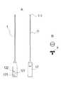
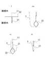
図1は、本実施の形態の構成図で、外筒管内に内針及びループワイヤーが収納された体表穿刺段階での状態、図2は、前記状態から内針を突出させたヘルニア門縁部周囲の腹膜外を運針し剥離している段階での状態、図3は、前記状態からループワイヤーを突出させたループへの縫合糸の取付け、取り外しの段階での状態を示している。また、図4は、本形態の外筒管(図A)、及び、係止ネジ(図B)、図5は、内筒管、図6はスタイレットを示している。Hereinafter, embodiments of the ligature transporter of the present invention will be described in detail with reference to the drawings.
FIG. 1 is a configuration diagram of the present embodiment, and shows a state in a body surface puncture stage in which an inner needle and a loop wire are housed in an outer tube, and FIG. 2 shows a hernia portal edge in which the inner needle is protruded from the state. FIG. 3 shows a state where the suture is attached to and detached from the loop from which the loop wire is projected from the above state. 4 shows an outer tube (FIG. A) and a locking screw (FIG. B), FIG. 5 shows an inner tube, and FIG. 6 shows a stylet.
本例の結紮糸輸送器は、小切開を置く鼠径部の皮膚を穿刺するための刃先111を備えた外管11と、該外管11の基部で把持操作部となる外筒基12からなる外筒管1と、前記外管11の内腔に摺動可能に挿入され、外管11先端から突出した形態、及び、外管内に収納された形態を採ることができる、先端211が刃先を備えない直断の内管21と、該内管21の基部で操作部となる内管基22からなる内筒管2と、前記内管21の内腔に摺動可能に挿入されるロッド31と、該ロッド31の先端に接続されて、前記内管21先端から突出し展開された形態、及び、先端部を僅かに残しほぼ全体を内管内に収納した潰れた形態を採ることができるループワイヤー32と、前記ロッド31の基部で把持操作部となるロッド基33からなるスタイレット3、及び、前記外管基12と内管基22を軸方向にスライド摺動及び固定可能に接続する係止ネジ4とより基本構成され、外筒管1内に内筒管2を、内筒管2内にスタイレット3を配置し、外管基12と内管基22、内管基22とロット基33が、それぞれ規定の長さを軸方向にスライド摺動可能で、かつ、規定の位置で固定可能に接続されて形成された。 The ligature transporter of this example includes an
外筒管1の外管11は、穿刺のための鋭利な刃先を備えたステンレス合金等の金属パイプより形成される。該外管11の基部に接続される外管基12は、内管基22を収容する内腔を備えた筒状の樹脂成形品として形成され、側面には、内管基22を軸方向に規定の長さ摺動するためのスライド溝121が形成され、該スライド溝121の両端部の周方向に連接して内筒管2のスライドを規制するロック部として、先端側に内管21の突出の位置を規制する突出側ロック部122、基側に内管21の収納位置を規制する収納側ロック部123が開口部として設けられている。
そして、該スライド溝121あるいはロック部122、123を貫通するように係止ネジ4が取り付けられ、ネジ部41を締め付けることで外筒管1と内筒管2が固定され、締め付けを緩めることでスライド摺動が可能となるよう形成されるThe
And the locking
内筒管2の内管21は、施術のさいに組織を損傷しないように鋭利な刃先を備えない、直断面に面取りを施した鈍な先端部211を備えるステンレス合金等の金属パイプにより形成され、前記外管11の内腔に摺動可能に挿入され、かつ、ロッド31を摺動可能に内挿可能な外径に、また、前記外管11内に収容でき、かつ、規定の長さ突出する長さに形成される。該内管21の基部に接続される内管基22は、ロッド基33を収容する内腔を備えた筒状の樹脂成形品として形成され、側面には前記係止ネジ4により外筒基12と接続するための雌ネジとして形成されるネジ受け孔221と、ロッド基33を軸方向に規定の長さ(ループワイヤー32の突出の長さ)摺動するためのスリット222、及び、スリット222後端部の周方向に連接してスタイレット3の収納位置でスライドを規制する突起係止部223が開口部として設けられる。また、スリット222に連接する同軸上に該スリット222より細径に形成する切込み224が、後記するロッド基33の係合突起331の挿入部として設けられる。 The
スタイレット3のロッド31は、前記内管21の内腔に摺動可能に挿入される外径のステンレス合金等の金属パイプあるいは棒より形成される。該ロッド31の先端に接続されるループワイヤー32は、超弾性合金など弾性に優れたワイヤーにより、自然状態で適当なループに展開される様に癖付けされて形成されており、弾性により前記内管21内に収納されるさいは押し潰され細径化される。尚、本例においては、中間部が凹んだ立体的な六角形に形成され、これにより、収納したさい内管21の内腔との接触面積が大きくなり、内部でのぶれが小さくなるようになっている。一方、前記ロッド31の基部に接続されるロッド基33は、前記内管基22の内腔に摺動可能な樹脂成形品として形成され、側面には内管基22のスリット222と係合してスライドし、突起係止部223に係合することで係止する係合突起331が設けられ、基端側は内管22内に挿入されない把持部332として形成される。 The
そして、外筒管1内に内筒管2が、内筒管2内にスタイレット3が内挿された3重管として形成されるが、外筒管1と内筒管2は、前記の通り外管基12の開口部のスライド溝121あるいはロック部122、123と、内管基22の雌ねじ形状のネジ受け孔221を係止ネジ4で螺合することにより接続され、該係止ネジ4の螺合を緩めることによりスライド溝121の範囲でスライドされ、該溝121の先端側端部で僅かに回動して突出ロック部122で螺合されることで内管21が外管11より突出された鈍な先端211が突出した状態で固定され、一方、後端側端部で僅かに回動して収納ロック部123で螺合されることで内管21が外管11に収納され鋭利な刃先111が突出した穿刺可能状態で固定される。尚、前記ロック部122、123がスライド軸より僅かに回動する位置に設定されることで意図しない、外管11の刃先111あるいは、内管21の突出を確実に防止している。 An
また、内筒管2とスタイレット3は、内管基22のスリット222にロッド基33の係合突起331を内管基22の切れ込み224から押込んで係合することにより接続され、スリット222の範囲でスライドされ、係合突起331がスリット222の先端部にあるときは、ループワイヤー32が内管先端221より突出され展開されており、後端部にあり、突起係止部223に係止されているときは、ループワイヤー32は内管21内に僅かに先端が突出した状態で収納されている。尚、前記突起係止部223がスライド軸より僅かに回動する位置に設定されることで意図しないループワイヤー32の突出を確実に防止している。 Further, the
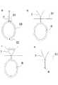
次に本形態の結紮糸輸送器を用いたLPEC法の手順を図8〜12を参照しながら説明する。
1.腹腔内に腹腔鏡や鉗子を配置した後、本輸送器を体内へ穿刺する前、内管21からループワイヤー32を突出させた状態でループに縫合糸7を通し(図8a)、ロッド基33の操作(ロッド基33の係合突起331を内管基22のスリット222に沿って後退させ、僅かに回動して突起係止部223に位置させる)によりワイヤーループ32を内管21内に収容して縫合糸7を先端に保持し、内管基22の操作(係止ネジ4を緩め、外管基12のスライド溝121に沿って後退させ、僅かに回動して係止ネジ4を収納ロック部123に位置させ、ネジ4を締め付けて固定する)により内管21を外管11内に収納して(図8b)穿刺の準備とする。
2.鼠径部に小切開を置き、該切開部から外管11を穿刺し(図8c)、刃先111をヘルニア門上縁に位置させ、腹腔鏡下に該位置が確認できたら外管基11の操作(係止ネジ4を緩め、外管基12のスライド溝121に沿って引き戻し、僅かに回動して係止ネジ4を突出ロック部122に位置させ、ネジを締め付けて固定する)により縫合糸7が保持された内管21を外管11から突出させる。(図8d)
3.この状態で、腹腔鏡で観察しながら輸送器の先端をヘルニア門上縁81から下縁82に向かい外側縁83(左右どちらか側)に沿って(矢印方向)腹膜外を剥離しながら運針し(図9e)、ヘルニア門下縁82まで剥離できたら、該下縁82の位置で腹腔外から腹腔内に腹膜92を穿破する。(図9f)
4.器具先端が腹腔内に位置したら、ロッド基33の操作(係止突起331を僅かに回動し突起係止部223から外し、内管基22のスリット222を前進させる)により内管基22からループワイヤー32を突出展開させ(図9g)、鉗子を用いてループから縫合糸7を外し(図10h)、再びロッド基33の操作(前記同様)によりループワイヤー32を内管21内に収納する。(図10i)尚、このさいにはループワイヤー32に縫合糸7は保持されていない。
5.この状態で、輸送器の先端をヘルニア門上縁81まで引き戻す(矢印方向)。(図10j)これまでの操作により縫合糸7は、体外から、腹腔外のヘルニア門8の半周囲を通って、ヘルニア門下縁82で腹腔内まで通されており、縫合糸7の先端部は腹腔内に残されている。
6.輸送器の先端をヘルニア門上縁81に戻したら、今度は、該ヘルニア門8の反対側の内側縁84に沿って(矢印方向)ヘルニア門下縁82まで腹膜外を剥離しながら運針し(図10k)、ヘルニア門下縁82まで剥離できたら、該下縁82の位置で腹腔外から腹腔内に向け腹膜92を穿破する。(図11l)
7.器具先端が腹腔内に位置したら、ロッド基33の操作(前記同様)により内管22からループワイヤー32を突出展開し(図11m)、腹腔内に残された縫合糸7の先端部を、鉗子を用いてループ内に通し(図11n)、ロッド基33の操作(前記同様)により縫合糸7をループワイヤー32の先端に保持した状態で内管21内に収納する。(図11o)
8.この状態で、輸送器を引き戻し(矢印方向)体外に取り出す。(図12p)この操作により縫合糸7は、体外部からヘルニア門上縁81、外側縁83の腹膜外を通り、下縁82で腹膜内に出され、更に該下縁82から内側縁84の腹膜外を通って先端部が体外部に取り出される。即ち、縫合糸7の両端部を体外に置き、ヘルニア門8一周囲を廻らせた配置となる。(図12q)
9.そして、体外に取り出された縫合糸7の両端部を結紮することで、(図12r)ヘルニア門8が縫縮される。(図12s)尚、縫合糸7の結び目は皮下に埋没される。Next, the procedure of the LPEC method using the ligature transporter of this embodiment will be described with reference to FIGS.
1. After placing the laparoscope and forceps in the abdominal cavity and before puncturing the transporter into the body, the
2. Place a small incision in the groin, puncture the
3. In this state, while observing with a laparoscope, the tip of the transporter is moved from the
4). When the distal end of the instrument is located within the abdominal cavity, the
5. In this state, the tip of the transporter is pulled back to the hernia upper edge 81 (in the direction of the arrow). (FIG. 10j) Through the operation so far, the
6). When the tip of the transporter is returned to the hernia gate
7). When the distal end of the instrument is located in the abdominal cavity, the
8). In this state, the transporter is pulled back (in the direction of the arrow) and taken out from the body. (FIG. 12p) By this operation, the
9. Then, the
本形態の結紮糸輸送器を用いてのLPEC法によると、ヘルニア門8一周囲に腹腔外を剥離しながら縫合糸7を廻らせるさい、鋭利な刃先を持たない内管21を先端部として処置することにより、従来のLPEC手技で問題となっていた男児に対する精巣や精巣動静脈の損傷の可能性を抑えることができ、また、3重針の各々のスライド操作の他、確実なロック手段を備えることで、意図しない針管、ワイヤーの突出等の動作を防止することができるなど、患者にとって安全で、術者にとって操作性の良い器具となっている。 According to the LPEC method using the ligature transporter of this embodiment, when the
1. 外筒管
11. 外管
111.刃先
12. 外管基
121.スライド溝
122.突出ロック部
123.収納ロック部
2. 内筒管
21. 内管
211.先端
22. 内管基
221.ネジ受け孔
222.スリット
223.突起係止部
224.切れ込み
3. スタイレット
31. ロッド
32. ループワイヤー
33. ロッド基
331.係合突起
332.把持部
4. 係止ネジ
7. 縫合糸
8. ヘルニア門
81. ヘルニア門上縁
82. ヘルニア門下縁
83. ヘルニア門外側縁
84. ヘルニア門内側縁
91. 皮膚
92. 腹膜1.
Claims (4)
Translated fromJapanesePriority Applications (1)
| Application Number | Priority Date | Filing Date | Title |
|---|---|---|---|
| JP2015021101AJP6441105B2 (en) | 2015-02-05 | 2015-02-05 | Ligature transporter |
Applications Claiming Priority (1)
| Application Number | Priority Date | Filing Date | Title |
|---|---|---|---|
| JP2015021101AJP6441105B2 (en) | 2015-02-05 | 2015-02-05 | Ligature transporter |
Publications (2)
| Publication Number | Publication Date |
|---|---|
| JP2016140696Atrue JP2016140696A (en) | 2016-08-08 |
| JP6441105B2 JP6441105B2 (en) | 2018-12-19 |
Family
ID=56569443
Family Applications (1)
| Application Number | Title | Priority Date | Filing Date |
|---|---|---|---|
| JP2015021101AActiveJP6441105B2 (en) | 2015-02-05 | 2015-02-05 | Ligature transporter |
Country Status (1)
| Country | Link |
|---|---|
| JP (1) | JP6441105B2 (en) |
Cited By (1)
| Publication number | Priority date | Publication date | Assignee | Title |
|---|---|---|---|---|
| CN107320139A (en)* | 2017-08-04 | 2017-11-07 | 重庆医科大学 | Laparoscope single hole multi-path Rotating-manipulatiodevice device |
Citations (12)
| Publication number | Priority date | Publication date | Assignee | Title |
|---|---|---|---|---|
| US4254762A (en)* | 1979-10-23 | 1981-03-10 | Inbae Yoon | Safety endoscope system |
| JPH04317646A (en)* | 1991-01-15 | 1992-11-09 | Ethicon Inc | Surgical trocar knife |
| WO1996001132A1 (en)* | 1994-07-01 | 1996-01-18 | Northgate Technologies Incorporated | High flow insufflation instrument for laparoscopic surgery |
| US5501692A (en)* | 1994-01-28 | 1996-03-26 | Riza; Erol D. | Laparoscopic suture snare |
| JPH09135841A (en)* | 1995-11-14 | 1997-05-27 | Olympus Optical Co Ltd | Aeroperitoneum needle |
| JPH09173342A (en)* | 1995-12-18 | 1997-07-08 | Siegfried Dr Med Riek | Needle for medical treatment |
| US5746752A (en)* | 1995-11-08 | 1998-05-05 | Arthrex, Inc. | Double-diameter knot pusher |
| JP2003225241A (en)* | 2002-01-30 | 2003-08-12 | Shoshi Sho | Therapeutic manipulator for endoscope |
| JP2003325659A (en)* | 2002-05-10 | 2003-11-18 | Hakko Medical:Kk | Drainage apparatus for laparoscopic operation |
| JP2007516790A (en)* | 2003-12-24 | 2007-06-28 | アクセスクロージャー,インク. | Device for delivering a sealing material and promoting hemostasis during a transdermal procedure |
| JP2007524425A (en)* | 2003-03-18 | 2007-08-30 | デピユイ・マイテク・インコーポレーテツド | Expandable needle suturing device and associated handle assembly |
| JP2007252408A (en)* | 2006-03-20 | 2007-10-04 | Terumo Corp | Suturing instrument for living body |
- 2015
- 2015-02-05JPJP2015021101Apatent/JP6441105B2/enactiveActive
Patent Citations (12)
| Publication number | Priority date | Publication date | Assignee | Title |
|---|---|---|---|---|
| US4254762A (en)* | 1979-10-23 | 1981-03-10 | Inbae Yoon | Safety endoscope system |
| JPH04317646A (en)* | 1991-01-15 | 1992-11-09 | Ethicon Inc | Surgical trocar knife |
| US5501692A (en)* | 1994-01-28 | 1996-03-26 | Riza; Erol D. | Laparoscopic suture snare |
| WO1996001132A1 (en)* | 1994-07-01 | 1996-01-18 | Northgate Technologies Incorporated | High flow insufflation instrument for laparoscopic surgery |
| US5746752A (en)* | 1995-11-08 | 1998-05-05 | Arthrex, Inc. | Double-diameter knot pusher |
| JPH09135841A (en)* | 1995-11-14 | 1997-05-27 | Olympus Optical Co Ltd | Aeroperitoneum needle |
| JPH09173342A (en)* | 1995-12-18 | 1997-07-08 | Siegfried Dr Med Riek | Needle for medical treatment |
| JP2003225241A (en)* | 2002-01-30 | 2003-08-12 | Shoshi Sho | Therapeutic manipulator for endoscope |
| JP2003325659A (en)* | 2002-05-10 | 2003-11-18 | Hakko Medical:Kk | Drainage apparatus for laparoscopic operation |
| JP2007524425A (en)* | 2003-03-18 | 2007-08-30 | デピユイ・マイテク・インコーポレーテツド | Expandable needle suturing device and associated handle assembly |
| JP2007516790A (en)* | 2003-12-24 | 2007-06-28 | アクセスクロージャー,インク. | Device for delivering a sealing material and promoting hemostasis during a transdermal procedure |
| JP2007252408A (en)* | 2006-03-20 | 2007-10-04 | Terumo Corp | Suturing instrument for living body |
Cited By (2)
| Publication number | Priority date | Publication date | Assignee | Title |
|---|---|---|---|---|
| CN107320139A (en)* | 2017-08-04 | 2017-11-07 | 重庆医科大学 | Laparoscope single hole multi-path Rotating-manipulatiodevice device |
| CN107320139B (en)* | 2017-08-04 | 2023-06-09 | 重庆医科大学 | Laparoscopic single-hole multi-channel rotatable operating device |
Also Published As
| Publication number | Publication date |
|---|---|
| JP6441105B2 (en) | 2018-12-19 |
Similar Documents
| Publication | Publication Date | Title |
|---|---|---|
| US5797927A (en) | Combined tissue clamping and suturing instrument | |
| EP1602336B1 (en) | System for accessing a body cavity | |
| JP5624819B2 (en) | Apparatus and method for transvaginal surgery | |
| JP6266024B2 (en) | Surgical tool introducer | |
| US9386980B2 (en) | Wound closure device including direct-driven needle | |
| JP6302842B2 (en) | Insertion device and insertion system for laparoscopic instruments | |
| CN106572874B (en) | The scissors end effector and application method of pin type | |
| JP5974192B2 (en) | Marking system | |
| WO2009073619A2 (en) | Transcervical excision and removal of tissue | |
| US20110082473A1 (en) | Wound closure device including releasable barbs | |
| US10660636B2 (en) | Suture apparatus, system and method | |
| CN105748121B (en) | Laparoscopic Puncture Stapler | |
| JP2016525376A (en) | Minimally invasive surgical assembly and method | |
| US10143466B2 (en) | Devices, systems, and methods for wound closure | |
| JP2016054988A (en) | Medical needle | |
| US8968341B2 (en) | Wound closure device | |
| JP6441105B2 (en) | Ligature transporter | |
| JP7713965B2 (en) | Device for laparoscopic access and wound closure - Patents.com | |
| JP2018525175A (en) | Surgical instrument with stop guard | |
| CN112244913A (en) | A microtraumatic retractor for laparoscopic thoracoscopy | |
| CN205814365U (en) | A kind of single-hole laparoscopic indirect inguinal hernia in children hernia ring separation ligature carrier | |
| JP3725795B2 (en) | Trocar mantle | |
| CN203388902U (en) | Special-purpose wire needle for minimally invasive surgery of laparoscopic pediatric hernia | |
| Jawad | Scroto-peritoneal port for laparoscopic orchidopexy | |
| Lau et al. | Technique for safe placement of reusable trocars during endoscopic extraperitoneal inguinal hernioplasty |
Legal Events
| Date | Code | Title | Description |
|---|---|---|---|
| A621 | Written request for application examination | Free format text:JAPANESE INTERMEDIATE CODE: A621 Effective date:20180119 | |
| A131 | Notification of reasons for refusal | Free format text:JAPANESE INTERMEDIATE CODE: A131 Effective date:20181016 | |
| A521 | Request for written amendment filed | Free format text:JAPANESE INTERMEDIATE CODE: A523 Effective date:20181022 | |
| A977 | Report on retrieval | Free format text:JAPANESE INTERMEDIATE CODE: A971007 Effective date:20181017 | |
| TRDD | Decision of grant or rejection written | ||
| A01 | Written decision to grant a patent or to grant a registration (utility model) | Free format text:JAPANESE INTERMEDIATE CODE: A01 Effective date:20181112 | |
| A61 | First payment of annual fees (during grant procedure) | Free format text:JAPANESE INTERMEDIATE CODE: A61 Effective date:20181121 | |
| R150 | Certificate of patent or registration of utility model | Ref document number:6441105 Country of ref document:JP Free format text:JAPANESE INTERMEDIATE CODE: R150 |