JP2016134530A - Processing control apparatus, processing control program, and processing control method - Google Patents
Processing control apparatus, processing control program, and processing control methodDownload PDFInfo
- Publication number
- JP2016134530A JP2016134530AJP2015008834AJP2015008834AJP2016134530AJP 2016134530 AJP2016134530 AJP 2016134530AJP 2015008834 AJP2015008834 AJP 2015008834AJP 2015008834 AJP2015008834 AJP 2015008834AJP 2016134530 AJP2016134530 AJP 2016134530A
- Authority
- JP
- Japan
- Prior art keywords
- light emission
- emission amount
- light
- etching
- total
- Prior art date
- Legal status (The legal status is an assumption and is not a legal conclusion. Google has not performed a legal analysis and makes no representation as to the accuracy of the status listed.)
- Pending
Links
Images


Classifications
- H—ELECTRICITY
- H01—ELECTRIC ELEMENTS
- H01J—ELECTRIC DISCHARGE TUBES OR DISCHARGE LAMPS
- H01J37/00—Discharge tubes with provision for introducing objects or material to be exposed to the discharge, e.g. for the purpose of examination or processing thereof
- H01J37/32—Gas-filled discharge tubes
- H01J37/32917—Plasma diagnostics
- H01J37/32926—Software, data control or modelling
- H—ELECTRICITY
- H01—ELECTRIC ELEMENTS
- H01J—ELECTRIC DISCHARGE TUBES OR DISCHARGE LAMPS
- H01J37/00—Discharge tubes with provision for introducing objects or material to be exposed to the discharge, e.g. for the purpose of examination or processing thereof
- H01J37/32—Gas-filled discharge tubes
- H01J37/32917—Plasma diagnostics
- H01J37/32935—Monitoring and controlling tubes by information coming from the object and/or discharge
- H01J37/32972—Spectral analysis
- H—ELECTRICITY
- H01—ELECTRIC ELEMENTS
- H01L—SEMICONDUCTOR DEVICES NOT COVERED BY CLASS H10
- H01L21/00—Processes or apparatus adapted for the manufacture or treatment of semiconductor or solid state devices or of parts thereof
- H01L21/67—Apparatus specially adapted for handling semiconductor or electric solid state devices during manufacture or treatment thereof; Apparatus specially adapted for handling wafers during manufacture or treatment of semiconductor or electric solid state devices or components ; Apparatus not specifically provided for elsewhere
- H01L21/67005—Apparatus not specifically provided for elsewhere
- H01L21/67242—Apparatus for monitoring, sorting or marking
- H01L21/67253—Process monitoring, e.g. flow or thickness monitoring
- H—ELECTRICITY
- H01—ELECTRIC ELEMENTS
- H01L—SEMICONDUCTOR DEVICES NOT COVERED BY CLASS H10
- H01L21/00—Processes or apparatus adapted for the manufacture or treatment of semiconductor or solid state devices or of parts thereof
- H01L21/70—Manufacture or treatment of devices consisting of a plurality of solid state components formed in or on a common substrate or of parts thereof; Manufacture of integrated circuit devices or of parts thereof
- H01L21/71—Manufacture of specific parts of devices defined in group H01L21/70
- H01L21/76—Making of isolation regions between components
- H01L21/762—Dielectric regions, e.g. EPIC dielectric isolation, LOCOS; Trench refilling techniques, SOI technology, use of channel stoppers
- H01L21/76224—Dielectric regions, e.g. EPIC dielectric isolation, LOCOS; Trench refilling techniques, SOI technology, use of channel stoppers using trench refilling with dielectric materials
- H—ELECTRICITY
- H01—ELECTRIC ELEMENTS
- H01L—SEMICONDUCTOR DEVICES NOT COVERED BY CLASS H10
- H01L22/00—Testing or measuring during manufacture or treatment; Reliability measurements, i.e. testing of parts without further processing to modify the parts as such; Structural arrangements therefor
- H01L22/20—Sequence of activities consisting of a plurality of measurements, corrections, marking or sorting steps
- H01L22/26—Acting in response to an ongoing measurement without interruption of processing, e.g. endpoint detection, in-situ thickness measurement
Landscapes
- Physics & Mathematics (AREA)
- Chemical & Material Sciences (AREA)
- Engineering & Computer Science (AREA)
- Plasma & Fusion (AREA)
- Analytical Chemistry (AREA)
- Spectroscopy & Molecular Physics (AREA)
- Drying Of Semiconductors (AREA)
- Materials Engineering (AREA)
- Mechanical Engineering (AREA)
- Metallurgy (AREA)
- Organic Chemistry (AREA)
Abstract
Description
Translated fromJapanese本発明の実施形態は、加工制御装置、加工制御プログラムおよび加工制御方法に関する。 Embodiments described herein relate generally to a machining control device, a machining control program, and a machining control method.
プラズマを用いたドライエッチング加工の際には、エッチング量を制御する必要がある。エッチング量の制御方法の1つとして、ドライエッチング加工のエッチング時間を制御する方法がある。また、エッチング量の制御方法の1つとして、ドライエッチング加工を実行した後にエッチング後のパターン寸法を測長し、測長値をフィードバックすることによってエッチング量を制御する方法がある。しかしながら、上記の2つの方法では、エッチング量を精度よく制御することが困難であった。 In dry etching processing using plasma, it is necessary to control the etching amount. One method of controlling the etching amount is a method of controlling the etching time for dry etching. As one method for controlling the etching amount, there is a method of controlling the etching amount by measuring the pattern dimension after etching after performing dry etching and feeding back the measured value. However, with the above two methods, it is difficult to accurately control the etching amount.
本発明が解決しようとする課題は、エッチング量を精度よく制御することができる加工制御装置、加工制御プログラムおよび加工制御方法を提供することである。 The problem to be solved by the present invention is to provide a machining control device, a machining control program, and a machining control method capable of accurately controlling the etching amount.
実施形態によれば加工制御装置が提供される。前記加工制御装置は、発光量算出部と、処理制御部と、を備えている。前記発光量算出部は、基板に対してプラズマを用いたドライエッチング加工が実行されている間に発生した光の中から所定波長の光を選択する。そして、前記処理制御部は、選択した光の発光強度を前記選択した光の検出された時間で積分した積分値を算出する。さらに、前記処理制御部は、前記積分値の合計値を前記基板での合計発光量として算出する。また、処理制御部は、前記合計発光量が所定の基準値に到達した場合に、前記ドライエッチング加工を停止させる指示を出力する。 According to the embodiment, a machining control device is provided. The processing control device includes a light emission amount calculation unit and a processing control unit. The light emission amount calculation unit selects light having a predetermined wavelength from light generated while dry etching using plasma is performed on the substrate. The processing control unit calculates an integral value obtained by integrating the emission intensity of the selected light with the detected time of the selected light. Further, the processing control unit calculates a total value of the integral values as a total light emission amount on the substrate. Further, the process control unit outputs an instruction to stop the dry etching process when the total light emission amount reaches a predetermined reference value.
以下に添付図面を参照して、実施形態に係る加工制御装置、加工制御プログラムおよび加工制御方法を詳細に説明する。なお、この実施形態により本発明が限定されるものではない。 Hereinafter, a machining control device, a machining control program, and a machining control method according to an embodiment will be described in detail with reference to the accompanying drawings. In addition, this invention is not limited by this embodiment.
(実施形態)
図1は、実施形態に係るドライエッチング装置の構成を示す図である。ドライエッチング装置1は、加工部9と、制御装置(加工制御装置)10とを備えている。ドライエッチング装置1は、ウェハWaなどの基板にドライエッチング加工を行う装置である。本実施形態のドライエッチング装置1は、エッチング時の発光強度に基づいて、エッチング量を制御する。(Embodiment)
FIG. 1 is a diagram illustrating a configuration of a dry etching apparatus according to an embodiment. The dry etching apparatus 1 includes a
加工部9は、チャンバ2と、ステージ3と、アンテナコイル4と、ブロッキングコンデンサ5と、高周波電源6,7と、発光強度測定部8とを備える。なお、ここでは図示を省略したが、ドライエッチング装置1は、チャンバ2内へ反応性ガスを供給するガス供給部と、チャンバ2内部の雰囲気をチャンバ2の外部へ排気する排気部とを備える。 The
チャンバ2は、RIE(Reactive Ion Etching)を行う処理室である。チャンバ2は、グランドに接続され、内部にステージ3が設けられている。ステージ3は、載置されるウェハWaなどの半導体基板(処理対象基板)を保持するテーブルである。ステージ3は、ブロッキングコンデンサ5および高周波電源6を介してグランドに接続されている。アンテナコイル4は、チャンバ2の天板上に設けられた平面視渦巻き状のコイルである。アンテナコイル4は、高周波電源7を介してグランドに接続されている。 The chamber 2 is a processing chamber for performing RIE (Reactive Ion Etching). The chamber 2 is connected to the ground, and the
ドライエッチング装置1は、チャンバ2の内部へ反応性ガスを導入する。ドライエッチング装置1は、チャンバ2の内部を略真空にした状態で、高周波電源7からアンテナコイル4へ高周波電圧を印加する。さらに、ドライエッチング装置1は、高周波電源6からステージ3へ高周波電圧を印加して反応性ガスをプラズマ化する。 The dry etching apparatus 1 introduces a reactive gas into the chamber 2. The dry etching apparatus 1 applies a high frequency voltage from the high
プラズマ中の電子は、アンテナコイル4に面するチャンバ2の天井、およびステージ3へ引き寄せられる。チャンバ2の天井に引き寄せられる電子は、チャンバ2がグランドに接続されているためグランドへ流れる。このため、チャンバ2の天井の電位は一定となる。一方、ブロッキングコンデンサ5は、直流電流を遮断するので、引き寄せる電子を蓄積して上部電極が負に帯電する。 Electrons in the plasma are attracted to the ceiling of the chamber 2 facing the antenna coil 4 and the
ドライエッチング装置1は、プラズマ中の陽イオンを負に帯電したブロッキングコンデンサ5へ引き寄せ、ステージ3に載置されるウェハWaに衝突させることによってRIEを行う。 The dry etching apparatus 1 performs RIE by attracting positive ions in the plasma to a negatively charged blocking capacitor 5 and colliding with a wafer Wa placed on the
発光強度測定部8は、ウェハWaに対してエッチング(プラズマを用いたドライエッチング加工)が行われている間に発生する光の強度(発光強度)を測定する。チャンバ2内でエッチングが行われると、ウェハWa上の被エッチング膜およびエッチングに用いられるガスの種類に応じた波長の光が発生する。発光強度測定部8は、発光強度を測定し、測定結果を制御装置10に送る。発光強度測定部8は、例えば、チャンバ2内などに配置されている。 The light emission
制御装置10は、加工部9に接続されており、加工部9を制御する。本実施形態の制御装置10は、発光強度に基づいて、RIEの終了タイミングを制御する。制御装置10は、所定の波長に対応する発光強度波形の積分値を合算していき、積分値の合計値(総和量)が、予め設定しておいた値に到達すると、RIEの終了タイミングであると判断する。 The
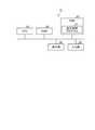
図2は、実施形態に係る制御装置の構成を示す図である。制御装置10は、入力部11と、発光量算出部12と、記憶部13と、処理制御部14とを備えている。入力部11は、加工部9の発光強度測定部8に接続されている。入力部11は、発光強度測定部8から送られてくる発光強度を受信して発光量算出部12に送る。 FIG. 2 is a diagram illustrating a configuration of the control device according to the embodiment. The
また、入力部11へは、ユーザなどによって、加工条件が入力される。入力部11は、入力された加工条件を発光量算出部12に送る。入力部11へは、例えば、後述する(1)〜(8)の情報が、加工条件として入力される。なお、入力部11へは、例えば、後述する(1)〜(8)の組合せを示す情報が加工条件として入力されてもよい。 In addition, processing conditions are input to the
発光量算出部12は、測定された光の中から所定波長の光を選択し、選択した光の発光強度の波形に基づいて、発光量の合計値(以下、合計発光量という)を算出する。発光量算出部12が算出する合計発光量は、発光強度を処理時間で積分した値の合計値である。発光量算出部12は、被エッチング膜およびエッチングガスに応じた波長の発光光に対して合計発光量を算出する。具体的には、発光量算出部12は、発光強度の波形の中から被エッチング膜およびエッチングガスに応じた波長の波形を抽出する。そして、発光量算出部12は、抽出した波形を時間積分(選択した光が検出されている時間で積分)し、時間積分した値(面積)を合計する。発光量算出部12は、算出した合計値を合計発光量として、処理制御部14に送る。また、発光量算出部12は、入力部11から送られてきた加工条件を処理制御部14に送る。 The light emission
記憶部13は、加工条件毎の発光量基準値を記憶する。発光量基準値は、エッチング処理の終了が判断される際の基準値である。したがって、算出された合計発光量が、基準値に到達すると、エッチング処理は終了となる。 The storage unit 13 stores a light emission amount reference value for each processing condition. The light emission amount reference value is a reference value for determining the end of the etching process. Therefore, when the calculated total light emission amount reaches the reference value, the etching process ends.
発光量基準値は、加工条件毎に設定されている。加工条件には、エッチング時のパワー、圧力、ガス種などがある。加工条件は、例えば、以下の(1)〜(8)などである。
(1)被エッチング膜の種類
(2)エッチングガスの種類
(3)エッチング時のTCP(Transformer Coupled Plasma)パワー
(4)エッチング時のバイアスパワー
(5)エッチング時のチャンバ2内の圧力
(6)エッチング時のガス流量
(7)エッチング時のデューティサイクル
(8)ウェハWaの開口率The light emission amount reference value is set for each processing condition. Processing conditions include power during etching, pressure, and gas type. The processing conditions are, for example, the following (1) to (8).
(1) Type of film to be etched (2) Type of etching gas (3) TCP (Transformer Coupled Plasma) power during etching (4) Bias power during etching (5) Pressure in chamber 2 during etching (6) Gas flow rate during etching (7) Duty cycle during etching (8) Aperture ratio of wafer Wa
(2)に示したエッチングガスの種類は、エッチングに用いられるメインガスの種類である。メインガスには、例えば、塩素、フッ素などがある。(6)に示したエッチング時のガス流量は、エッチングに用いられるメインガスの流量である。(7)に示したエッチング時のデューティサイクルは、バイアスがオン/オフされるサイクルの全体時間に対するバイアスオン時間の比率である。 The type of etching gas shown in (2) is the type of main gas used for etching. Examples of the main gas include chlorine and fluorine. The gas flow rate during etching shown in (6) is the flow rate of the main gas used for etching. The duty cycle during etching shown in (7) is the ratio of the bias on time to the total time of the cycle in which the bias is turned on / off.
(8)に示したウェハWaの開口率は、ウェハWa上面の全体面積に対する被エッチング膜の面積の比率(被覆率)である。ウェハWaでは、被エッチング膜の上部にマスク材が形成されている。そして、ウェハWaのうち、マスク材の形成されていない箇所がエッチングされる。例えば、ウェハWaの最上層面がラインパターンなどのマスク材であり、マスク材の配置されていない箇所がスペースパターンである。このようなウェハWaでは、スペースパターンよりも下層側がエッチングされる。そして、ウェハWa上面の全体面積に対するスペースパターンの面積が、ウェハWaの開口率である。 The aperture ratio of the wafer Wa shown in (8) is the ratio (coverage) of the area of the film to be etched to the entire area of the upper surface of the wafer Wa. In the wafer Wa, a mask material is formed on the etching target film. Then, a portion of the wafer Wa where no mask material is formed is etched. For example, the uppermost layer surface of the wafer Wa is a mask material such as a line pattern, and a portion where no mask material is arranged is a space pattern. In such a wafer Wa, the lower layer side of the space pattern is etched. The area of the space pattern with respect to the entire area of the upper surface of the wafer Wa is the aperture ratio of the wafer Wa.
記憶部13は、例えば、上述した(1)〜(8)の組合せである加工条件と、発光量基準値との対応関係を記憶しておく。 The storage unit 13 stores, for example, the correspondence relationship between the processing conditions that are combinations of the above (1) to (8) and the light emission amount reference value.
処理制御部14は、ユーザによって指定された加工条件に対応する発光量基準値を記憶部13から抽出する。処理制御部14は、発光量算出部12から送られてくる合計発光量が、抽出した発光量基準値に到達したか否かを判断する。処理制御部14は、発光量算出部12から送られてくる合計発光量が、抽出した発光量基準値に到達すると、エッチング処理の終了指示を加工部9に送る。 The
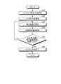
つぎに、実施形態に係るエッチング処理の処理手順について説明する。図3は、実施形態に係るエッチング処理の処理手順を示すフローチャートである。エッチングの開始前には、エッチング前の寸法測定が行われる(ステップS10)。エッチング前の寸法測定は、エッチングの前工程が完了した後に行われる処理である。エッチング前の寸法測定では、ウェハWa上のパターン寸法が測定される。具体的には、エッチング前の寸法測定では、例えば、エッチングの際に用いられるマスクパターンの寸法や、マスクで覆われていない被エッチング膜の寸法などが測定される。 Next, a processing procedure of the etching process according to the embodiment will be described. FIG. 3 is a flowchart showing a processing procedure of the etching process according to the embodiment. Before the start of etching, dimension measurement before etching is performed (step S10). The dimension measurement before etching is a process performed after the pre-etching process is completed. In the dimension measurement before etching, the pattern dimension on the wafer Wa is measured. Specifically, in the dimension measurement before etching, for example, the dimension of a mask pattern used in etching, the dimension of a film to be etched that is not covered with a mask, and the like are measured.
そして、ユーザが制御装置10に加工条件を入力すると、ドライエッチング装置1は、ウェハWaへのエッチングを開始する(ステップS20)。このとき、制御装置10は、ユーザから指定された加工条件でウェハWaがエッチングされるよう加工部9を制御する。 When the user inputs processing conditions to the
加工部9がエッチングを開始すると、発光強度測定部8は、ウェハWa近傍での発光強度を測定する(ステップS30)。発光強度測定部8は、測定した発光強度(測定結果)を制御装置10に送る。制御装置10の入力部11は、発光強度測定部8から送られてくる発光強度を受信して発光量算出部12に送る。発光量算出部12は、発光強度の波形に基づいて、合計発光量を算出する(ステップS40)。 When the
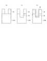
図4は、エッチング処理の処理例を説明するための図である。図4の(a)〜(c)では、ウェハWa上に形成されているパターンの断面図を示している。図4の(a)に示すように、ウェハWaでは、被エッチング膜31A上にマスク32が形成されている。そして、ウェハWaに対しては、マスク32上からエッチングが行われる。 FIG. 4 is a diagram for explaining an example of the etching process. 4A to 4C are cross-sectional views of patterns formed on the wafer Wa. As shown in FIG. 4A, in the wafer Wa, a
マスク32をマスクとして被エッチング膜31Aがエッチングされると、図4の(b)に示すように、被エッチング膜31Aは、穴部33が設けられた被エッチング膜31Bとなる。 When the
この後、図4の(c)に示すように、ウェハWa上には、側壁保護膜34が形成される。側壁保護膜34は、マスク32の側壁面を保護する膜である。側壁保護膜34は、マスク32の上面および側壁面と、穴部33の底面および側壁面とを覆うように形成される。 Thereafter, as shown in FIG. 4C, a sidewall
この後、図4の(b)に示した被エッチング膜31Bを掘り下げる処理(穴部33を深くする処理)と、図4の(c)に示した側壁保護膜34を形成する処理とが繰り返される。図4の(b)および(c)の繰り返し処理が、エッチングサイクルプロセスである。エッチングサイクルプロセスによって、被エッチング膜31Bには、所定の深さを有した穴部33が設けられる。 Thereafter, the process of digging up the
本実施形態では、所望の深さの穴部33でエッチングを終了するために、エッチング時の発光強度が測定される。そして、エッチング時の発光強度に基づいて、合計発光量が算出され、合計発光量に基づいて、エッチングの終了タイミングが判断される。 In the present embodiment, in order to complete the etching at the
図5は、発光強度の波形例を示す図である。ここでは、ウェハWa上に形成された、ゲート酸化膜層およびPoly層からなる積層構造を、RIE法にて加工した場合の波形例について説明する。 FIG. 5 is a diagram illustrating a waveform example of the emission intensity. Here, an example of a waveform when a laminated structure formed on the wafer Wa and including a gate oxide film layer and a Poly layer is processed by the RIE method will be described.
図5の(a)では、発光強度の第1の波形例(発光強度特性101)を示し、図5の(b)では、発光強度の第2の波形例(発光強度特性102)を示している。図5の(a)および図5の(b)に示すグラフの横軸は時間であり、縦軸は発光強度である。 5A shows a first waveform example (emission intensity characteristic 101) of the emission intensity, and FIG. 5B shows a second waveform example (emission intensity characteristic 102) of the emission intensity. Yes. The horizontal axis of the graphs shown in FIGS. 5A and 5B is time, and the vertical axis is emission intensity.
発光強度特性101は、1枚のウェハWaに対してエッチング処理(Si加工)を5回繰り返した場合の特性を示している。また、発光強度特性102は、1枚のウェハWaに対してエッチング処理を7回繰り返した場合の特性を示している。エッチング処理の際には、例えば、以下の条件などが用いられる。
TCP Power:700W
Bias Voltage:650W
Cl2:100sccm
O2:0〜10sccm
圧力:15mTorr
デューティサイクル:15〜30%A light emission intensity characteristic 101 indicates a characteristic when etching processing (Si processing) is repeated five times on one wafer Wa. The light emission intensity characteristic 102 is a characteristic when the etching process is repeated seven times on one wafer Wa. In the etching process, for example, the following conditions are used.
TCP Power: 700W
Bias Voltage: 650W
Cl2 : 100 sccm
O2 : 0 to 10 sccm
Pressure: 15mTorr
Duty cycle: 15-30%
発光強度特性101,102は、種々のタイミングで大きくなる。すなわち、発光強度特性101,102は、複数の波(凸形状の波)を有している。発光強度が大きくなるタイミング(波)のうち、ウェハWaへのエッチング処理によって発生するものが、波51である。波51は、例えば、波長425nmの発光に対応する波である。換言すると、Si(シリコン膜)加工中に得られるプラズマ発光のうち、波長425nmの発光が、波51である。 The
発光強度特性101,102のうち、波51以外の波は、エッチングとは異なる処理(形状維持プロセスなど)の際に発生する波である。加工部9では、エッチング処理と、エッチングとは異なる処理とが、繰り返される。 Of the
発光量算出部12は、エッチング処理によって発生する波51の発光量を算出する。このとき、発光量算出部12は、発光強度を処理時間(波51が発生している時間)で積分することによって波51の発光量を算出する。波51は、複数回発生するので、発光量算出部12は、各波51に対する発光量を算出する。そして、発光量算出部12は、波51の各発光量を加算することによって、合計発光量を算出する。 The light emission
1枚のウェハWaに対して5回のエッチング処理が行われた場合、発光量算出部12は、5つの波51に対して合計発光量を算出する。また、1枚のウェハWaに対して7回のエッチング処理が行われた場合、発光量算出部12は、7つの波51に対して合計発光量を算出する。 When the etching process is performed five times for one wafer Wa, the light emission
発光量算出部12は、算出した合計発光量を、処理制御部14に送る。また、発光量算出部12は、入力部11から送られてきた加工条件を処理制御部14に送る。 The light emission
処理制御部14は、入力部11から送られてきた加工条件に対応する発光量基準値を記憶部13から抽出する。処理制御部14は、発光量算出部12から送られてくる合計発光量が、抽出した発光量基準値に到達したか否かを判断する(ステップS50)。 The
処理制御部14は、発光量算出部12から送られてくる合計発光量が、抽出した発光量基準値に到達していなければ(ステップS50、No)、エッチング処理の終了指示を加工部9に送らない。この結果、加工部9では、エッチング処理が継続される。これにより、発光強度測定部8は、発光強度の測定を継続する(ステップS30)。そして、発光量算出部12は、合計発光量の算出を継続する(ステップS40)。このとき、処理制御部14は、発光量算出部12から送られてくる合計発光量が、発光量基準値に到達したか否かの判断を継続している(ステップS50)。 If the total light emission amount sent from the light emission
処理制御部14は、発光量算出部12から送られてくる合計発光量が、抽出した発光量基準値に到達すると(ステップS50、Yes)、エッチング処理の終了指示を加工部9に送る。 When the total light emission amount sent from the light emission
これにより、加工部9は、エッチングを終了し(ステップS60)、ウェハWaを外部に搬出する。制御装置10は、合計発光量が予め設定された196000となるようエッチングを制御したところ、Si加工のstep数によらず所望のSiトレンチ深さを得ることができた。 Thereby, the
本実施形態では、合計発光量が同じであれば、同じトレンチ深さを得ることができる。換言すると、1枚のウェハWaに対してN回(Nは自然数)のエッチング処理が行われた場合、合計発光量が同じであれば、合計発光量に応じたトレンチ深さを得ることができる。例えば、5回のエッチング処理が行われた場合の合計発光量と、7回のエッチング処理が行われた場合の合計発光量と、が同じである場合、同じトレンチ深さを得ることができる。 In the present embodiment, the same trench depth can be obtained if the total light emission amount is the same. In other words, when the etching process is performed N times (N is a natural number) for one wafer Wa, the trench depth corresponding to the total light emission amount can be obtained if the total light emission amount is the same. . For example, when the total light emission amount when the etching process is performed five times and the total light emission amount when the etching process is performed seven times are the same, the same trench depth can be obtained.
なお、制御装置10は、複数の波長に対して合計発光量を算出し、算出した合計発光量に基づいて、エッチング量を制御してもよい。この場合、波長毎に予め複数の発光量基準値の範囲(発光量基準範囲)を設定しておく。例えば、記憶部13へは、第1の波長(例えば、波長425nm)に対応する第1の発光量基準範囲(例えば、196000±1000)と、第2の波長(例えば、波長256nm)に対応する第2の発光量基準範囲(例えば、220000±2000)と、を記憶させておく。 In addition, the
そして、発光量算出部12は、エッチングの際に発生するプラズマ発光のうち、第1の波長の第1の合計発光量と、第2の波長の第2の合計発光量と、を算出する。さらに、処理制御部14は、第1の合計発光量が第1の発光量基準範囲内となり、かつ第2の合計発光量が第2の発光量基準範囲内となったタイミングを、エッチングの終了タイミングであると判断する。これにより、制御装置10は、マスク残膜の膜厚および被エッチング膜の膜厚を所望の厚さに制御することが可能となる。この結果、ドライエッチング装置1は、例えば、所望のマスク残膜およびSiトレンチ深さを得ることができる。 Then, the light emission
なお、発光量算出部12は、第1の合計発光量が第1の発光量基準範囲内から第1の発光量基準範囲外となった場合に、エッチングを停止させてもよい。また、発光量算出部12は、第2の合計発光量が第2の発光量基準範囲内から第2の発光量基準範囲外となった場合に、エッチングを停止させてもよい。 Note that the light emission
また、発光量算出部12は、第1の合計発光量が第1の発光量基準値(例えば、195000)に到達し、かつ第2の合計発光量が第2の発光量基準値(例えば、219600)に到達したタイミングを、エッチングの終了タイミングであると判断してもよい。 In addition, the light emission
また、発光量算出部12は、第1の合計発光量が第1の発光量基準値に到達するか、または、第2の合計発光量が第2の発光量基準値に到達したタイミングを、エッチングの終了タイミングであると判断してもよい。 In addition, the light emission
また、発光量算出部12は、3つ以上の光の合計発光量と、各光に対応する発光量基準値または発光量基準範囲と、に基づいて、エッチングの終了タイミングを判断してもよい。 Further, the light emission
ところで、エッチング時間に基づいて、エッチングの終了時間を決定する場合、エッチング量のばらつきが大きくなる。また、APC(Advanced Process Control)制御を用いてエッチングの終了時間を決定する方法がある。この方法では、エッチングを所定量まで完了させた後に、ウェハWa上のパターン寸法(エッチング後寸法)が測定される。そして、測定結果が後続のウェハ加工にフィードバックされる。これにより、後続のウェハWaは、測定結果に応じたタイミングでエッチングが完了する。ところが、この方法の場合、フィードバックがかかるまでタイムラグが生じるので、深さ制御のできていないロットが発生する場合がある。本実施形態では、エッチングの処理中にエッチングを終了させるタイミングを算出できるので、全てのロットに対してタイムラグを発生させることなく適切なエッチング制御を実行できる。 By the way, when the etching end time is determined based on the etching time, the variation in the etching amount becomes large. Further, there is a method of determining an etching end time using APC (Advanced Process Control) control. In this method, after the etching is completed to a predetermined amount, the pattern dimension (post-etching dimension) on the wafer Wa is measured. The measurement result is fed back to subsequent wafer processing. As a result, the subsequent wafer Wa is completely etched at a timing according to the measurement result. However, in the case of this method, a time lag occurs until feedback is applied, so that a lot whose depth is not controlled may occur. In the present embodiment, since the timing for ending the etching during the etching process can be calculated, appropriate etching control can be executed for all the lots without causing a time lag.
ドライエッチング装置1は、例えば、RIEによってSTI(Shallow Trench Isolation)用のトレンチを形成する製造工程などで用いられる。なお、本実施形態に係る半導体装置の製造方法は、製造工程中にドライエッチングが含まれるものであれば、任意の半導体装置の製造方法への適用が可能である。 The dry etching apparatus 1 is used, for example, in a manufacturing process for forming a trench for STI (Shallow Trench Isolation) by RIE. Note that the semiconductor device manufacturing method according to this embodiment can be applied to any semiconductor device manufacturing method as long as dry etching is included in the manufacturing process.
ドライエッチング装置1は、例えば、ウェハプロセスのレイヤ毎に用いられる。半導体装置(半導体集積回路)が製造される際には、ウェハWa上に被エッチング膜が形成される。そして、被エッチング膜上にレジストが塗布される。この後、レジストの塗布されたウェハWaにフォトマスクなどを用いて露光が行なわれる。その後、ウェハWaが現像されることによって、ウェハWa上にレジストパターンが形成される。そして、レジストパターンをマスクとして被エッチング膜がドライエッチング装置1によってエッチングされる。これにより、レジストパターンに対応する実パターンがウェハWa上に形成される。半導体装置を製造する際には、被エッチング膜の形成処理、レジストの塗布処理、露光処理、現像処理、エッチング処理などがレイヤ毎に繰り返される。なお、半導体装置が製造される際には、露光処理および現像処理の代わりにインプリント処理などが用いられてもよい。 The dry etching apparatus 1 is used for each layer of a wafer process, for example. When a semiconductor device (semiconductor integrated circuit) is manufactured, a film to be etched is formed on the wafer Wa. Then, a resist is applied on the film to be etched. Thereafter, the resist-coated wafer Wa is exposed using a photomask or the like. Thereafter, by developing the wafer Wa, a resist pattern is formed on the wafer Wa. Then, the film to be etched is etched by the dry etching apparatus 1 using the resist pattern as a mask. Thereby, an actual pattern corresponding to the resist pattern is formed on the wafer Wa. When manufacturing a semiconductor device, a film forming process, a resist coating process, an exposure process, a developing process, an etching process, and the like are repeated for each layer. When a semiconductor device is manufactured, an imprint process or the like may be used instead of the exposure process and the development process.
つぎに、制御装置10のハードウェア構成について説明する。図6は、制御装置のハードウェア構成を示す図である。制御装置10は、CPU(Central Processing Unit)91、ROM(Read Only Memory)92、RAM(Random Access Memory)93、表示部94、入力部95を有している。制御装置10では、これらのCPU91、ROM92、RAM93、表示部94、入力部95がバスラインを介して接続されている。 Next, a hardware configuration of the
CPU91は、コンピュータプログラムである加工制御プログラム97を用いてパターンの判定を行う。加工制御プログラム97は、コンピュータで実行可能な、加工を制御するための複数の命令を含むコンピュータ読取り可能かつ非遷移的な記録媒体(nontransitory computer readable medium)を有するコンピュータプログラムプロダクトである。加工制御プログラム97では、前記複数の命令が加工を制御することをコンピュータに実行させる。 The
表示部94は、液晶モニタなどの表示装置であり、CPU91からの指示に基づいて、加工条件、発光強度の波形、合計発光量、発光量基準値、エッチングの状態(エッチング中、エッチング終了)などを表示する。入力部95は、マウスやキーボードを備えて構成され、使用者から外部入力される指示情報(加工制御に必要なパラメータおよび加工条件等)を入力する。入力部95へ入力された指示情報は、CPU91へ送られる。 The
加工制御プログラム97は、ROM92内に格納されており、バスラインを介してRAM93へロードされる。図6では、加工制御プログラム97がRAM93へロードされた状態を示している。 The
CPU91はRAM93内にロードされた加工制御プログラム97を実行する。具体的には、制御装置10では、使用者による入力部95からの指示入力に従って、CPU91がROM92内から加工制御プログラム97を読み出してRAM93内のプログラム格納領域に展開して各種処理を実行する。CPU91は、この各種処理に際して生じる各種データをRAM93内に形成されるデータ格納領域に一時的に記憶させておく。 The
制御装置10で実行される加工制御プログラム97は、発光量算出部12、処理制御部14を含むモジュール構成となっており、これらが主記憶装置上にロードされ、これらが主記憶装置上に生成される。 The
このように実施形態によれば、発光量算出部が合計発光量を算出し、合計発光量が所定の基準値に到達した場合に、処理制御部がドライエッチング加工を停止させる指示を出力するので、合計発光量に応じたタイミングでドライエッチング加工を停止させることができる。したがって、エッチング量を精度よく制御することが可能となる。 As described above, according to the embodiment, the light emission amount calculation unit calculates the total light emission amount, and when the total light emission amount reaches a predetermined reference value, the process control unit outputs an instruction to stop the dry etching process. The dry etching process can be stopped at a timing according to the total light emission amount. Therefore, the etching amount can be controlled with high accuracy.
本発明のいくつかの実施形態を説明したが、これらの実施形態は、例として提示したものであり、発明の範囲を限定することは意図していない。これら新規な実施形態は、その他の様々な形態で実施されることが可能であり、発明の要旨を逸脱しない範囲で、種々の省略、置き換え、変更を行うことができる。これら実施形態やその変形は、発明の範囲や要旨に含まれるとともに、特許請求の範囲に記載された発明とその均等の範囲に含まれる。 Although several embodiments of the present invention have been described, these embodiments are presented by way of example and are not intended to limit the scope of the invention. These novel embodiments can be implemented in various other forms, and various omissions, replacements, and changes can be made without departing from the scope of the invention. These embodiments and modifications thereof are included in the scope and gist of the invention, and are included in the invention described in the claims and the equivalents thereof.
1…ドライエッチング装置、2…チャンバ、6,7…高周波電源、8…発光強度測定部、9…加工部、10…制御装置、11…入力部、12…発光量算出部、13…記憶部、14…処理制御部、31A,31B…被エッチング膜、32…マスク、33…穴部、34…側壁保護膜、101,102…発光強度特性、Wa…ウェハ。 DESCRIPTION OF SYMBOLS 1 ... Dry etching apparatus, 2 ... Chamber, 6, 7 ... High frequency power supply, 8 ... Luminescence intensity measurement part, 9 ... Processing part, 10 ... Control apparatus, 11 ... Input part, 12 ... Luminescence amount calculation part, 13 ... Memory |
Claims (5)
Translated fromJapanese前記合計発光量が所定の基準値に到達した場合に、前記ドライエッチング加工を停止させる指示を出力する処理制御部と、
を備えることを特徴とする加工制御装置。Select light of a predetermined wavelength from the light generated while dry etching processing using plasma is performed on the substrate, and integrate the emission intensity of the selected light at the detected time of the selected light A light emission amount calculation unit that calculates the integrated value, and calculates the total value of the integral values as the total light emission amount on the substrate;
A processing control unit that outputs an instruction to stop the dry etching process when the total light emission amount reaches a predetermined reference value;
A machining control device comprising:
ことを特徴とする請求項1に記載の加工制御装置。The light emission amount calculation unit selects light generated while the etching target film disposed on the lower layer side of the mask pattern on the substrate is processed as light having the predetermined wavelength.
The processing control apparatus according to claim 1, wherein
ことを特徴とする請求項1に記載の加工制御装置。The light emission amount calculation unit selects light having a wavelength corresponding to the type of the film to be etched and the type of gas used in the dry etching process as the light having the predetermined wavelength.
The processing control apparatus according to claim 1, wherein
前記合計発光量が所定の基準値に到達した場合に、前記ドライエッチング加工を停止させる指示を出力する処理制御ステップと、
をコンピュータに実行させることを特徴とする加工制御プログラム。Select light of a predetermined wavelength from the light generated while dry etching processing using plasma is performed on the substrate, and integrate the emission intensity of the selected light at the detected time of the selected light A light emission amount calculating step of calculating the integrated value, and calculating a total value of the integrated values as a total light emission amount on the substrate;
A process control step for outputting an instruction to stop the dry etching process when the total light emission amount reaches a predetermined reference value;
A machining control program for causing a computer to execute the above.
選択した光の発光強度を前記選択した光の検出された時間で積分した積分値を算出する積分値算出ステップと、
前記積分値の合計値を前記基板での合計発光量として算出する合計発光量算出ステップと、
前記合計発光量が所定の基準値に到達した場合に、前記ドライエッチング加工を停止させる指示を出力する出力ステップと、
を含むことを特徴とする加工制御方法。A selection step of selecting light of a predetermined wavelength from light generated while dry etching using plasma is performed on the substrate;
An integral value calculating step for calculating an integral value obtained by integrating the emission intensity of the selected light with the detected time of the selected light;
A total light emission amount calculating step of calculating a total value of the integrated values as a total light emission amount on the substrate;
An output step of outputting an instruction to stop the dry etching process when the total light emission amount reaches a predetermined reference value;
The processing control method characterized by including.
Priority Applications (2)
| Application Number | Priority Date | Filing Date | Title |
|---|---|---|---|
| JP2015008834AJP2016134530A (en) | 2015-01-20 | 2015-01-20 | Processing control apparatus, processing control program, and processing control method |
| US14/657,581US9859103B2 (en) | 2015-01-20 | 2015-03-13 | Process control device, recording medium, and process control method |
Applications Claiming Priority (1)
| Application Number | Priority Date | Filing Date | Title |
|---|---|---|---|
| JP2015008834AJP2016134530A (en) | 2015-01-20 | 2015-01-20 | Processing control apparatus, processing control program, and processing control method |
Publications (1)
| Publication Number | Publication Date |
|---|---|
| JP2016134530Atrue JP2016134530A (en) | 2016-07-25 |
Family
ID=56407375
Family Applications (1)
| Application Number | Title | Priority Date | Filing Date |
|---|---|---|---|
| JP2015008834APendingJP2016134530A (en) | 2015-01-20 | 2015-01-20 | Processing control apparatus, processing control program, and processing control method |
Country Status (2)
| Country | Link |
|---|---|
| US (1) | US9859103B2 (en) |
| JP (1) | JP2016134530A (en) |
Cited By (1)
| Publication number | Priority date | Publication date | Assignee | Title |
|---|---|---|---|---|
| JP2018113306A (en)* | 2017-01-10 | 2018-07-19 | 東京エレクトロン株式会社 | Substrate processing method and substrate processing apparatus |
Families Citing this family (60)
| Publication number | Priority date | Publication date | Assignee | Title |
|---|---|---|---|---|
| US9132436B2 (en) | 2012-09-21 | 2015-09-15 | Applied Materials, Inc. | Chemical control features in wafer process equipment |
| US10256079B2 (en) | 2013-02-08 | 2019-04-09 | Applied Materials, Inc. | Semiconductor processing systems having multiple plasma configurations |
| US9966240B2 (en) | 2014-10-14 | 2018-05-08 | Applied Materials, Inc. | Systems and methods for internal surface conditioning assessment in plasma processing equipment |
| US9355922B2 (en) | 2014-10-14 | 2016-05-31 | Applied Materials, Inc. | Systems and methods for internal surface conditioning in plasma processing equipment |
| US11637002B2 (en) | 2014-11-26 | 2023-04-25 | Applied Materials, Inc. | Methods and systems to enhance process uniformity |
| US10573496B2 (en) | 2014-12-09 | 2020-02-25 | Applied Materials, Inc. | Direct outlet toroidal plasma source |
| US20160225652A1 (en) | 2015-02-03 | 2016-08-04 | Applied Materials, Inc. | Low temperature chuck for plasma processing systems |
| US9728437B2 (en) | 2015-02-03 | 2017-08-08 | Applied Materials, Inc. | High temperature chuck for plasma processing systems |
| US9741593B2 (en) | 2015-08-06 | 2017-08-22 | Applied Materials, Inc. | Thermal management systems and methods for wafer processing systems |
| US9691645B2 (en) | 2015-08-06 | 2017-06-27 | Applied Materials, Inc. | Bolted wafer chuck thermal management systems and methods for wafer processing systems |
| US9349605B1 (en) | 2015-08-07 | 2016-05-24 | Applied Materials, Inc. | Oxide etch selectivity systems and methods |
| US10504700B2 (en) | 2015-08-27 | 2019-12-10 | Applied Materials, Inc. | Plasma etching systems and methods with secondary plasma injection |
| US10522371B2 (en) | 2016-05-19 | 2019-12-31 | Applied Materials, Inc. | Systems and methods for improved semiconductor etching and component protection |
| US10504754B2 (en) | 2016-05-19 | 2019-12-10 | Applied Materials, Inc. | Systems and methods for improved semiconductor etching and component protection |
| US9865484B1 (en) | 2016-06-29 | 2018-01-09 | Applied Materials, Inc. | Selective etch using material modification and RF pulsing |
| US10629473B2 (en) | 2016-09-09 | 2020-04-21 | Applied Materials, Inc. | Footing removal for nitride spacer |
| US10546729B2 (en) | 2016-10-04 | 2020-01-28 | Applied Materials, Inc. | Dual-channel showerhead with improved profile |
| US9934942B1 (en) | 2016-10-04 | 2018-04-03 | Applied Materials, Inc. | Chamber with flow-through source |
| US10163696B2 (en) | 2016-11-11 | 2018-12-25 | Applied Materials, Inc. | Selective cobalt removal for bottom up gapfill |
| US10026621B2 (en) | 2016-11-14 | 2018-07-17 | Applied Materials, Inc. | SiN spacer profile patterning |
| US10431429B2 (en) | 2017-02-03 | 2019-10-01 | Applied Materials, Inc. | Systems and methods for radial and azimuthal control of plasma uniformity |
| US10319739B2 (en) | 2017-02-08 | 2019-06-11 | Applied Materials, Inc. | Accommodating imperfectly aligned memory holes |
| US10943834B2 (en) | 2017-03-13 | 2021-03-09 | Applied Materials, Inc. | Replacement contact process |
| US11276590B2 (en) | 2017-05-17 | 2022-03-15 | Applied Materials, Inc. | Multi-zone semiconductor substrate supports |
| US11276559B2 (en) | 2017-05-17 | 2022-03-15 | Applied Materials, Inc. | Semiconductor processing chamber for multiple precursor flow |
| JP7176860B6 (en) | 2017-05-17 | 2022-12-16 | アプライド マテリアルズ インコーポレイテッド | Semiconductor processing chamber to improve precursor flow |
| US10497579B2 (en) | 2017-05-31 | 2019-12-03 | Applied Materials, Inc. | Water-free etching methods |
| US10920320B2 (en) | 2017-06-16 | 2021-02-16 | Applied Materials, Inc. | Plasma health determination in semiconductor substrate processing reactors |
| US10541246B2 (en) | 2017-06-26 | 2020-01-21 | Applied Materials, Inc. | 3D flash memory cells which discourage cross-cell electrical tunneling |
| US10727080B2 (en) | 2017-07-07 | 2020-07-28 | Applied Materials, Inc. | Tantalum-containing material removal |
| US10541184B2 (en)* | 2017-07-11 | 2020-01-21 | Applied Materials, Inc. | Optical emission spectroscopic techniques for monitoring etching |
| US10043674B1 (en) | 2017-08-04 | 2018-08-07 | Applied Materials, Inc. | Germanium etching systems and methods |
| US10297458B2 (en) | 2017-08-07 | 2019-05-21 | Applied Materials, Inc. | Process window widening using coated parts in plasma etch processes |
| US11227779B2 (en)* | 2017-09-12 | 2022-01-18 | Asm Technology Singapore Pte Ltd | Apparatus and method for processing a semiconductor device |
| US10903054B2 (en) | 2017-12-19 | 2021-01-26 | Applied Materials, Inc. | Multi-zone gas distribution systems and methods |
| US11328909B2 (en) | 2017-12-22 | 2022-05-10 | Applied Materials, Inc. | Chamber conditioning and removal processes |
| US10854426B2 (en) | 2018-01-08 | 2020-12-01 | Applied Materials, Inc. | Metal recess for semiconductor structures |
| US10964512B2 (en) | 2018-02-15 | 2021-03-30 | Applied Materials, Inc. | Semiconductor processing chamber multistage mixing apparatus and methods |
| US10679870B2 (en) | 2018-02-15 | 2020-06-09 | Applied Materials, Inc. | Semiconductor processing chamber multistage mixing apparatus |
| TWI766433B (en) | 2018-02-28 | 2022-06-01 | 美商應用材料股份有限公司 | Systems and methods to form airgaps |
| US10593560B2 (en) | 2018-03-01 | 2020-03-17 | Applied Materials, Inc. | Magnetic induction plasma source for semiconductor processes and equipment |
| US10319600B1 (en) | 2018-03-12 | 2019-06-11 | Applied Materials, Inc. | Thermal silicon etch |
| US10497573B2 (en) | 2018-03-13 | 2019-12-03 | Applied Materials, Inc. | Selective atomic layer etching of semiconductor materials |
| US10573527B2 (en) | 2018-04-06 | 2020-02-25 | Applied Materials, Inc. | Gas-phase selective etching systems and methods |
| US10490406B2 (en) | 2018-04-10 | 2019-11-26 | Appled Materials, Inc. | Systems and methods for material breakthrough |
| US10699879B2 (en) | 2018-04-17 | 2020-06-30 | Applied Materials, Inc. | Two piece electrode assembly with gap for plasma control |
| US10886137B2 (en) | 2018-04-30 | 2021-01-05 | Applied Materials, Inc. | Selective nitride removal |
| US10755941B2 (en) | 2018-07-06 | 2020-08-25 | Applied Materials, Inc. | Self-limiting selective etching systems and methods |
| US10872778B2 (en) | 2018-07-06 | 2020-12-22 | Applied Materials, Inc. | Systems and methods utilizing solid-phase etchants |
| US10672642B2 (en) | 2018-07-24 | 2020-06-02 | Applied Materials, Inc. | Systems and methods for pedestal configuration |
| US10892198B2 (en) | 2018-09-14 | 2021-01-12 | Applied Materials, Inc. | Systems and methods for improved performance in semiconductor processing |
| US11049755B2 (en) | 2018-09-14 | 2021-06-29 | Applied Materials, Inc. | Semiconductor substrate supports with embedded RF shield |
| US11062887B2 (en) | 2018-09-17 | 2021-07-13 | Applied Materials, Inc. | High temperature RF heater pedestals |
| US11417534B2 (en) | 2018-09-21 | 2022-08-16 | Applied Materials, Inc. | Selective material removal |
| US11682560B2 (en) | 2018-10-11 | 2023-06-20 | Applied Materials, Inc. | Systems and methods for hafnium-containing film removal |
| US11121002B2 (en) | 2018-10-24 | 2021-09-14 | Applied Materials, Inc. | Systems and methods for etching metals and metal derivatives |
| US11437242B2 (en) | 2018-11-27 | 2022-09-06 | Applied Materials, Inc. | Selective removal of silicon-containing materials |
| US11721527B2 (en) | 2019-01-07 | 2023-08-08 | Applied Materials, Inc. | Processing chamber mixing systems |
| US10920319B2 (en) | 2019-01-11 | 2021-02-16 | Applied Materials, Inc. | Ceramic showerheads with conductive electrodes |
| JP7575201B2 (en)* | 2020-05-27 | 2024-10-29 | 東京エレクトロン株式会社 | Plasma treatment method |
Citations (6)
| Publication number | Priority date | Publication date | Assignee | Title |
|---|---|---|---|---|
| JPS63211633A (en)* | 1987-02-26 | 1988-09-02 | Tokuda Seisakusho Ltd | plasma etching equipment |
| JPH10163176A (en)* | 1996-12-03 | 1998-06-19 | Meidensha Corp | Manufacture of semiconductor element |
| JP2001044171A (en)* | 1999-07-28 | 2001-02-16 | Matsushita Electric Ind Co Ltd | Etching end point detection method and apparatus |
| JP2002190470A (en)* | 2000-12-22 | 2002-07-05 | Shibaura Mechatronics Corp | Etching equipment |
| JP2003147553A (en)* | 2001-11-07 | 2003-05-21 | Shibaura Mechatronics Corp | Etching end point detecting method and apparatus, and dry etching apparatus |
| JP2009117685A (en)* | 2007-11-08 | 2009-05-28 | Hitachi High-Technologies Corp | Plasma processing method for semiconductor device having high-k / metal structure |
Family Cites Families (6)
| Publication number | Priority date | Publication date | Assignee | Title |
|---|---|---|---|---|
| TW492106B (en)* | 2000-06-20 | 2002-06-21 | Hitachi Ltd | Inspection method for thickness of film to be processed using luminous beam-splitter and method of film processing |
| US6977184B1 (en)* | 2001-10-31 | 2005-12-20 | Lam Research Corporation | Method and apparatus for nitride spacer etch process implementing in situ interferometry endpoint detection and non-interferometry endpoint monitoring |
| JP5192850B2 (en) | 2008-02-27 | 2013-05-08 | 株式会社日立ハイテクノロジーズ | Etching end point judgment method |
| US8961804B2 (en)* | 2011-10-25 | 2015-02-24 | Applied Materials, Inc. | Etch rate detection for photomask etching |
| JP5862433B2 (en) | 2012-04-09 | 2016-02-16 | 株式会社島津製作所 | Surface treatment status monitoring device |
| JP5384758B2 (en) | 2013-01-31 | 2014-01-08 | 株式会社日立ハイテクノロジーズ | Plasma etching equipment |
- 2015
- 2015-01-20JPJP2015008834Apatent/JP2016134530A/enactivePending
- 2015-03-13USUS14/657,581patent/US9859103B2/enactiveActive
Patent Citations (6)
| Publication number | Priority date | Publication date | Assignee | Title |
|---|---|---|---|---|
| JPS63211633A (en)* | 1987-02-26 | 1988-09-02 | Tokuda Seisakusho Ltd | plasma etching equipment |
| JPH10163176A (en)* | 1996-12-03 | 1998-06-19 | Meidensha Corp | Manufacture of semiconductor element |
| JP2001044171A (en)* | 1999-07-28 | 2001-02-16 | Matsushita Electric Ind Co Ltd | Etching end point detection method and apparatus |
| JP2002190470A (en)* | 2000-12-22 | 2002-07-05 | Shibaura Mechatronics Corp | Etching equipment |
| JP2003147553A (en)* | 2001-11-07 | 2003-05-21 | Shibaura Mechatronics Corp | Etching end point detecting method and apparatus, and dry etching apparatus |
| JP2009117685A (en)* | 2007-11-08 | 2009-05-28 | Hitachi High-Technologies Corp | Plasma processing method for semiconductor device having high-k / metal structure |
Cited By (1)
| Publication number | Priority date | Publication date | Assignee | Title |
|---|---|---|---|---|
| JP2018113306A (en)* | 2017-01-10 | 2018-07-19 | 東京エレクトロン株式会社 | Substrate processing method and substrate processing apparatus |
Also Published As
| Publication number | Publication date |
|---|---|
| US9859103B2 (en) | 2018-01-02 |
| US20160208395A1 (en) | 2016-07-21 |
Similar Documents
| Publication | Publication Date | Title |
|---|---|---|
| JP2016134530A (en) | Processing control apparatus, processing control program, and processing control method | |
| KR102713607B1 (en) | Ion energy control by rf pulse shape | |
| TWI868672B (en) | Systems and methods for achieving peak ion energy enhancement with a low angular spread | |
| KR101116589B1 (en) | Apparatus and method for controlling etch depth | |
| TWI611478B (en) | Controlling cd and cd uniformity with trim time and temperature on a wafer by wafer basis | |
| JP4101280B2 (en) | Plasma etching method and plasma etching apparatus capable of detecting end point | |
| KR20210021400A (en) | Single energy ion generation for controlled etching | |
| JP2017143261A5 (en) | ||
| US6700090B2 (en) | Plasma processing method and plasma processing apparatus | |
| JP6200849B2 (en) | Plasma processing apparatus and dry etching method | |
| TWI661323B (en) | Simulation method, simulation program, process control system, simulator, process design method, and mask design method | |
| US20170186586A1 (en) | Plasma system, plasma processing method, and plasma etching method | |
| KR20070094528A (en) | Plasma processing method and plasma processing apparatus | |
| JP2019507957A (en) | Method for stripping implanted photoresist | |
| CN104730858A (en) | Uniformity in Wafer Patterning using Feedback Control | |
| WO2010095196A1 (en) | Plasma treatment method and plasma treatment device | |
| US11437289B2 (en) | Plasma processing apparatus and plasma processing method | |
| CN107924855B (en) | System and method for controlling an etch process | |
| TWI791269B (en) | Multiscale physical etch modeling and methods thereof | |
| JP6898149B2 (en) | How to plasma etch a workpiece | |
| KR20170004898A (en) | Determination of semiconductor chamber operating parameters for the optimization of critical dimension uniformity | |
| CN104471686A (en) | Plasma etching method and plasma etching apparatus | |
| JP2013115354A (en) | Simulation method, simulation program, semiconductor manufacturing apparatus | |
| JP4700922B2 (en) | Manufacturing method of semiconductor device | |
| JP5234591B2 (en) | Plasma etching method and plasma etching apparatus capable of detecting end point |
Legal Events
| Date | Code | Title | Description |
|---|---|---|---|
| A621 | Written request for application examination | Free format text:JAPANESE INTERMEDIATE CODE: A621 Effective date:20170227 | |
| A711 | Notification of change in applicant | Free format text:JAPANESE INTERMEDIATE CODE: A712 Effective date:20170605 | |
| A977 | Report on retrieval | Free format text:JAPANESE INTERMEDIATE CODE: A971007 Effective date:20171122 | |
| A131 | Notification of reasons for refusal | Free format text:JAPANESE INTERMEDIATE CODE: A131 Effective date:20180109 | |
| A521 | Request for written amendment filed | Free format text:JAPANESE INTERMEDIATE CODE: A523 Effective date:20180309 | |
| A02 | Decision of refusal | Free format text:JAPANESE INTERMEDIATE CODE: A02 Effective date:20180904 | |
| A711 | Notification of change in applicant | Free format text:JAPANESE INTERMEDIATE CODE: A712 Effective date:20180905 |