JP2016129315A - Display device, imaging device, imaging system, control method of display device, control method of imaging device, program, and recording medium - Google Patents
Display device, imaging device, imaging system, control method of display device, control method of imaging device, program, and recording mediumDownload PDFInfo
- Publication number
- JP2016129315A JP2016129315AJP2015003604AJP2015003604AJP2016129315AJP 2016129315 AJP2016129315 AJP 2016129315AJP 2015003604 AJP2015003604 AJP 2015003604AJP 2015003604 AJP2015003604 AJP 2015003604AJP 2016129315 AJP2016129315 AJP 2016129315A
- Authority
- JP
- Japan
- Prior art keywords
- display device
- captured image
- display
- imaging
- imaging device
- Prior art date
- Legal status (The legal status is an assumption and is not a legal conclusion. Google has not performed a legal analysis and makes no representation as to the accuracy of the status listed.)
- Granted
Links
Images


Classifications
- H—ELECTRICITY
- H04—ELECTRIC COMMUNICATION TECHNIQUE
- H04N—PICTORIAL COMMUNICATION, e.g. TELEVISION
- H04N1/00—Scanning, transmission or reproduction of documents or the like, e.g. facsimile transmission; Details thereof
- H04N1/00127—Connection or combination of a still picture apparatus with another apparatus, e.g. for storage, processing or transmission of still picture signals or of information associated with a still picture
- H04N1/00129—Connection or combination of a still picture apparatus with another apparatus, e.g. for storage, processing or transmission of still picture signals or of information associated with a still picture with a display device, e.g. CRT or LCD monitor
- H—ELECTRICITY
- H04—ELECTRIC COMMUNICATION TECHNIQUE
- H04N—PICTORIAL COMMUNICATION, e.g. TELEVISION
- H04N23/00—Cameras or camera modules comprising electronic image sensors; Control thereof
- H04N23/60—Control of cameras or camera modules
- H04N23/66—Remote control of cameras or camera parts, e.g. by remote control devices
- H—ELECTRICITY
- H04—ELECTRIC COMMUNICATION TECHNIQUE
- H04N—PICTORIAL COMMUNICATION, e.g. TELEVISION
- H04N23/00—Cameras or camera modules comprising electronic image sensors; Control thereof
- H04N23/60—Control of cameras or camera modules
- H04N23/63—Control of cameras or camera modules by using electronic viewfinders
- H—ELECTRICITY
- H04—ELECTRIC COMMUNICATION TECHNIQUE
- H04N—PICTORIAL COMMUNICATION, e.g. TELEVISION
- H04N23/00—Cameras or camera modules comprising electronic image sensors; Control thereof
- H04N23/60—Control of cameras or camera modules
- H04N23/64—Computer-aided capture of images, e.g. transfer from script file into camera, check of taken image quality, advice or proposal for image composition or decision on when to take image
- H—ELECTRICITY
- H04—ELECTRIC COMMUNICATION TECHNIQUE
- H04N—PICTORIAL COMMUNICATION, e.g. TELEVISION
- H04N23/00—Cameras or camera modules comprising electronic image sensors; Control thereof
- H04N23/60—Control of cameras or camera modules
- H04N23/68—Control of cameras or camera modules for stable pick-up of the scene, e.g. compensating for camera body vibrations
- H04N23/681—Motion detection
- H04N23/6812—Motion detection based on additional sensors, e.g. acceleration sensors
- H—ELECTRICITY
- H04—ELECTRIC COMMUNICATION TECHNIQUE
- H04N—PICTORIAL COMMUNICATION, e.g. TELEVISION
- H04N23/00—Cameras or camera modules comprising electronic image sensors; Control thereof
- H04N23/60—Control of cameras or camera modules
- H04N23/68—Control of cameras or camera modules for stable pick-up of the scene, e.g. compensating for camera body vibrations
- H04N23/682—Vibration or motion blur correction
- H04N23/684—Vibration or motion blur correction performed by controlling the image sensor readout, e.g. by controlling the integration time
- H04N23/6842—Vibration or motion blur correction performed by controlling the image sensor readout, e.g. by controlling the integration time by controlling the scanning position, e.g. windowing
- H—ELECTRICITY
- H04—ELECTRIC COMMUNICATION TECHNIQUE
- H04N—PICTORIAL COMMUNICATION, e.g. TELEVISION
- H04N23/00—Cameras or camera modules comprising electronic image sensors; Control thereof
- H04N23/80—Camera processing pipelines; Components thereof
- H—ELECTRICITY
- H04—ELECTRIC COMMUNICATION TECHNIQUE
- H04N—PICTORIAL COMMUNICATION, e.g. TELEVISION
- H04N5/00—Details of television systems
- H04N5/222—Studio circuitry; Studio devices; Studio equipment
- H04N5/262—Studio circuits, e.g. for mixing, switching-over, change of character of image, other special effects ; Cameras specially adapted for the electronic generation of special effects
- H04N5/2628—Alteration of picture size, shape, position or orientation, e.g. zooming, rotation, rolling, perspective, translation
- H—ELECTRICITY
- H04—ELECTRIC COMMUNICATION TECHNIQUE
- H04N—PICTORIAL COMMUNICATION, e.g. TELEVISION
- H04N23/00—Cameras or camera modules comprising electronic image sensors; Control thereof
- H04N23/60—Control of cameras or camera modules
- H04N23/667—Camera operation mode switching, e.g. between still and video, sport and normal or high- and low-resolution modes
Landscapes
- Engineering & Computer Science (AREA)
- Multimedia (AREA)
- Signal Processing (AREA)
- Studio Devices (AREA)
Abstract
Description
Translated fromJapanese本発明は、表示装置、撮像装置、撮像システム、表示装置の制御方法、撮像装置の制御方法、プログラム、及び記録媒体に関する。 The present invention relates to a display device, an imaging device, an imaging system, a display device control method, an imaging device control method, a program, and a recording medium.
近年、Wi−Fi(Wireless Fidelity)等の無線通信機能を用いることで、スマートフォンなどの外部端末から遠隔操作可能なデジタルスチルカメラ、デジタルカムコーダ等の撮像装置が開発され、普及している。この外部端末の遠隔操作機能により、ユーザが撮像装置から遠く離れた場所に居ても撮像装置を操作することが可能である。この機能により、ユーザは、撮像装置の撮像画像の確認のみではなく、撮影開始指示や撮影パラメータの設定を行うことも可能になっている。 In recent years, imaging devices such as digital still cameras and digital camcorders that can be remotely operated from an external terminal such as a smartphone by using a wireless communication function such as Wi-Fi (Wireless Fidelity) have been developed and are widely used. With this remote operation function of the external terminal, it is possible to operate the imaging apparatus even when the user is located far away from the imaging apparatus. With this function, the user can not only confirm the captured image of the imaging apparatus but also set the shooting start instruction and shooting parameters.
例えば、外部端末を用いて遠隔から撮像装置を操作する場合、ユーザが撮像装置の撮像画像を確認している際に、撮像画像の水平と被写体の水平とが一致していない状態に気づくことがある。しかしながら、外部端末を操作している撮影者(ユーザ)と撮像装置との距離が大きく離れていることがあるため、ユーザが撮像装置の位置や姿勢を修正することが困難な場合がある。 For example, when an imaging device is operated remotely using an external terminal, the user may notice that the horizontal level of the captured image and the horizontal level of the subject do not match when checking the captured image of the imaging device. is there. However, since the distance between the photographer (user) who operates the external terminal and the imaging apparatus may be far away, it may be difficult for the user to correct the position and orientation of the imaging apparatus.
そこで、ユーザが遠隔操作により撮像装置に対して回転角度指示を行うことで電子的に撮像画像の画角を補正する方法が提案されている(特許文献1参照)。また、撮像装置の傾き情報を用いることで撮像装置の水平を電子的に自動修正する方法が提案されている(特許文献2参照)。 Therefore, a method has been proposed in which the user electronically corrects the angle of view of the captured image by giving a rotation angle instruction to the imaging device by remote control (see Patent Document 1). In addition, a method has been proposed in which the horizontal position of the imaging device is electronically automatically corrected by using the tilt information of the imaging device (see Patent Document 2).
特許文献1によれば、クライアント端末が、ネットワークに接続されている撮像装置に対して、撮像画像の傾きを補正するための角度情報を送信することにより、撮像画像の傾きを電子的に補正する。この方法では、ユーザは、クライアント端末に表示されるスライドバーを操作することにより、撮像画像の傾きを補正するための角度を決定する。そして、遠隔に設置されている撮像装置は、角度情報を受信し、撮像画像を電子的に補正する。これにより、遠隔からの操作による撮像画像の傾きの補正が可能となる。 According to Patent Document 1, the client terminal electronically corrects the tilt of the captured image by transmitting angle information for correcting the tilt of the captured image to the imaging device connected to the network. . In this method, the user determines an angle for correcting the inclination of the captured image by operating a slide bar displayed on the client terminal. Then, the imaging device installed remotely receives the angle information and electronically corrects the captured image. This makes it possible to correct the tilt of the captured image by a remote operation.
特許文献2によれば、撮像装置が、撮像装置自体の傾き角度を検出し、その検出された角度情報を用いて撮像画像を補正する。この方法では、撮像装置内の角度センサー等で撮像装置自体の傾きが検出される。そして、撮像装置は、検出された角度情報を用いて撮像画像を電子的に補正する。これにより、自動で撮像画像の傾きを修正することが可能となる。 According to
しかしながら、特許文献1では、ユーザは、スライドバーの操作量と回転角度との関係を直感的に把握することが困難であり、撮像画像の傾きを素早く正確に補正することが困難である。また、特許文献2では、撮像装置が水平で被写体が傾いているような場合に対処できない。 However, in Patent Document 1, it is difficult for the user to intuitively understand the relationship between the operation amount of the slide bar and the rotation angle, and it is difficult to quickly and accurately correct the tilt of the captured image. Further,
本発明はこのような状況に鑑みてなされたものであり、撮像装置から撮像画像を受信して表示する表示装置のユーザが撮像画像を直感的に補正することを可能とする技術を提供することを目的とする。 The present invention has been made in view of such a situation, and provides a technique that allows a user of a display device that receives and displays a captured image from the imaging device to intuitively correct the captured image. With the goal.
上記課題を解決するために、本発明は、表示装置であって、撮像装置から撮像画像を受信する受信手段と、前記撮像画像を表示する表示手段と、前記表示装置の姿勢を検出する検出手段と、前記表示手段での前記撮像画像の表示中に前記検出手段により検出された姿勢を示す姿勢情報を前記撮像装置へ送信する送信手段と、を備えることを特徴とする表示装置を提供する。 In order to solve the above-described problem, the present invention provides a display device that includes a reception unit that receives a captured image from the imaging device, a display unit that displays the captured image, and a detection unit that detects the attitude of the display device. And a transmission unit that transmits posture information indicating the posture detected by the detection unit during display of the captured image on the display unit to the imaging device.
なお、その他の本発明の特徴は、添付図面及び以下の発明を実施するための形態における記載によって更に明らかになるものである。 Other features of the present invention will become more apparent from the accompanying drawings and the following description of the preferred embodiments.
本発明によれば、撮像装置から撮像画像を受信して表示する表示装置のユーザが撮像画像を直感的に補正することが可能となる。 According to the present invention, a user of a display device that receives and displays a captured image from the imaging device can intuitively correct the captured image.
以下、添付図面を参照して、本発明の実施形態を説明する。なお、本発明の技術的範囲は、特許請求の範囲によって確定されるのであって、以下の個別の実施形態によって限定されるわけではない。また、実施形態の中で説明されている特徴の組み合わせすべてが、本発明に必須とは限らない。 Embodiments of the present invention will be described below with reference to the accompanying drawings. The technical scope of the present invention is determined by the claims, and is not limited by the following individual embodiments. In addition, not all combinations of features described in the embodiments are essential to the present invention.
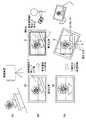
図1は、各実施形態に係る撮像システムに含まれる表示装置100及び撮像装置200の概略構成を示すブロック図である。表示装置100は、例えばユーザが手持ち可能な携帯端末(例えばスマートフォン)であり、ユーザが撮像装置200を遠隔から操作するために使用される。撮像装置200は、例えばデジタルカメラであり、電子的な画像処理により撮像画像の傾き及びあおりを補正する機能を有する。 FIG. 1 is a block diagram illustrating a schematic configuration of a
表示装置100は、通信処理部1により、ネットワーク上に接続されている撮像装置200との通信を行う。ここでは、表示装置100は、撮像装置200で撮像されている撮像画像をネットワークを通して受信する。また、表示装置100は、表示装置100の姿勢を示す姿勢情報を撮像装置200へ送信する。以下の各実施形態では、表示装置100の姿勢として表示装置100の角度を用いるものとし、姿勢情報を角度情報とも呼ぶ。表示装置100は、通信処理部1で受信した撮像装置200の撮像画像を表示部2に表示する。このとき、表示処理部3は、撮像画像を、表示装置100の表示部2で表示可能な情報に変換する。また、表示処理部3は、表示装置100の角度情報を表示部2で表示するための表示データを生成する。角度検出部4(姿勢検出手段)は、表示装置100の位置姿勢を検出し、検出結果を角度情報に変換する。角度検出部4としては、加速度センサーやジャイロセンサーなどを用いることができる。制御部5は、不揮発性のROM、及び揮発性のRAMを有し、ROMに格納された制御プログラムを実行することにより、表示装置100の制御を行う。制御部5のRAMは、制御部5が制御プログラムを実行するためのワークメモリとして使用される。なお、図1においては、表示処理部3が独立したブロックとして図示されているが、表示処理部3の処理を制御部5が実行してもよい。 The
撮像装置200は、撮像処理部6に含まれる撮像素子により被写体を撮像し、撮像データを得る。画像処理部7は、撮像データに基づいて撮像画像を生成する。また、画像処理部7は、通信処理部9を介して表示装置100から受信した角度情報に基づき、撮像画像の補正を電子的に行う。記録部10は、撮像画像を記録する。また、撮像装置200は、撮像装置200の撮影操作やメニュー設定などを行うための操作部11、及び、撮像画像や撮影情報などの確認を行うための表示部12を有する。更に、撮像装置200は、表示装置100に撮像画像を送信、又は、表示装置100の角度情報を受信するための通信処理部9を有する。制御部8は、不揮発性のROM、及び揮発性のRAMを有し、ROMに格納された制御プログラムを実行することにより、撮像装置200の制御を行う。制御部8のRAMは、制御部8が制御プログラムを実行するためのワークメモリとして使用される。 The
撮像装置200の各構成要素について更に詳細に説明する。撮像処理部6は、複数枚のレンズ、絞り等から構成される光学部、撮像素子、撮像素子を駆動するためのドライバ、タイミング生成回路、CDS/AGC回路等から構成される。光学部は、外部から入射した入射光量を調整するための絞り、NDフィルター(ND: Neutral Density)で構成される。また、撮像処理部6は、レンズ群を光軸に対して駆動することで、被写体に対する合焦や、手ぶれ等の撮像画像ぶれの軽減などを行う。撮像素子は、光電変換による被写体の撮像を行い、CDS/AGC回路により、撮像素子の各画素に蓄えられた電荷(画像信号)に基づく画像情報をサンプリング及び増幅する。なお、サンプリングでは相関二重サンプリング(CDS: Correlated Double Sampling)が、増幅では自動利得調整(AGC: Auto Gain Control)が行われる。A/D変換器は、CDS/AGC回路から出力された画像情報(アナログ信号)をデジタル信号に変換する。A/D変換器から出力された画像情報(デジタル信号)に対して画像処理部7によりAWB(auto white balance)、ガンマ制御等の種々の信号処理を行うことにより、撮像画像が生成される。また、撮像素子を駆動するためのドライバ、タイミング生成回路は、撮像素子を駆動するための駆動パルス等を撮像素子へ供給し、撮像素子で撮像した画像の読み出しや露出時間の調整を行う。 Each component of the
画像処理部7は、前述の通り、通信処理部9を介して受信した表示装置100の角度情報に基づき、撮像画像を電子的に補正する。ここでは、回転方向とあおり方向の補正を画像処理で行うものとする。 As described above, the
記録部10は、画像処理部7により生成した撮像画像を、画像ファイルとして、内部メモリ、又は、メモリーカード等の外部メモリ(記録媒体)に保存する。このとき、記録部10は、通信処理部9を介して受信した角度情報を画像ファイルに書き込むことができる。 The
ユーザは、操作部11を使用することで、撮像装置200の撮影時のキー操作、設定メニュー等の設定を行う。表示部12は、画像処理部7で生成した表示画像を表示する。水平検出部13は、撮像装置200の傾きを検出して角度情報を出力する。水平検出部13としては、加速度センサーやジャイロセンサーなどを用いることができる
なお、図1に示す各ブロックは、独立した回路部として図示されている。しかしながら、全て又は一部のブロックは、制御部5又は制御部8の中に含まれても構わない。The user uses the
[第1の実施形態]
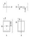
最初に、図2を参照して、第1の実施形態の概要について説明する。図2(a)に示すように、撮像装置200は、被写体を撮像するように設置されている。撮像処理部6により得られた撮像データから、画像処理部7により撮像画像が生成される。図2(a)の例では、撮像装置200は、地面に対して水平に設置されている。ここで、撮像装置200にとって「地面に対して水平」な方向は、撮像装置200の水平検出部13により検出される重力方向と垂直な方向を意味し、以下では単に「撮像装置200側で検出された水平方向」とも言う。一方、被写体は斜面に傾いて設置されている。[First Embodiment]
First, the outline of the first embodiment will be described with reference to FIG. As shown in FIG. 2A, the
図2(b)に示すように、撮像装置200は、撮像画像を表示部12に表示する。また、撮像装置200は、水平検出部13が出力する角度情報に基づき、水平線(撮像装置200の水平線)を表示部12に表示する。前述の通り撮像装置200は地面に対して水平に設置されているため、水平線は撮像画像の横方向と平行である。また、前述の通り被写体は斜面に傾いて設置されているため、図2(b)においても、撮像画像に含まれる被写体は傾いている。 As illustrated in FIG. 2B, the
なお、本実施形態では、撮像装置200が地面に対して水平であるものとして説明を行うが、撮像装置200の姿勢はこれに限定されない。撮像装置200は、地面に対して傾いて設置されていてもよい。この場合、水平線は、撮像装置200の水平検出部13により検出された傾きの分だけ傾いて(即ち、撮像画像の横方向に対して角度を付けて)表示される。 In the present embodiment, the
撮像装置200は、通信処理部9を介して、ネットワーク上に接続された表示装置100の通信処理部1に対して、撮像画像を送信する。このとき、撮像装置200は、撮像装置200の姿勢を示す情報も併せて送信する。ここでは、撮像装置200の姿勢を示す情報として、水平検出部13が出力する角度情報に基づいて得られる、撮像装置200の水平方向を示す情報(水平情報、撮像装置姿勢情報)が送信されるものとする。図2(b)に示すように、表示装置100は、通信処理部1を介して撮像装置200から受信した撮像画像を、表示処理部3により表示部2で表示可能な形式に変換し、表示部2に表示する。 The
撮影者(ユーザ)は、表示部2に表示中の撮像画像を確認しながら、表示装置100を回転させることにより、撮像画像の傾きを補正するための角度情報を決定する。ここでの回転は、表示部2の表示画面に直交する回転軸の周りで行われる(図9(a)の回転軸901参照)。また、例えば、図9(a)の左側に示すように表示画面の横線(左右の線)が地面に対して水平な場合の回転角度を0度と定義する。ここで、表示画面(又は表示装置100)にとって「地面に対して水平」な方向は、表示装置100の角度検出部4により検出される重力方向と垂直な方向を意味し、以下では単に「表示装置100側で検出された水平方向」とも言う。従って、回転角度が0度の状態は、水平補助線(図2(b)に示す補助線のうち横方向の線。詳細は後述。)が、表示画面の横線と平行な状態を意味する。また、補正対象である「撮像画像の傾き」は、この回転軸における撮像画像の回転による、表示装置100の水平補助線からの「ずれ」を指す。 The photographer (user) determines angle information for correcting the inclination of the captured image by rotating the
ユーザが表示装置100を回転させる際に、表示部2には、撮像画像に加えて、撮像装置200から受信した水平情報に基づく水平線、及び、表示装置100の回転角度(姿勢)を示す補助情報が表示される。本実施形態では、補助情報は、グリッド状の補助線であり、水平補助線及び垂直補助線を含むものとする。水平補助線と表示画面の横線とが成す角度が表示装置100の回転角度に対応する。水平線及び補助線は、表示処理部3により生成される。表示処理部3は、角度検出部4によって検出された角度情報に基づいて、表示装置100が回転しても水平補助線が表示装置100側で検出された水平方向を示し続けるように表示を更新する。従って、水平補助線を見ることで、ユーザは表示装置100側で検出された水平方向を確認することができる。 When the user rotates the
撮像画像の傾きを補正するために、ユーザは、撮像画像に含まれる被写体において、表示装置100側で検出された水平方向と一致すべき線を決定する。図2(b)の例では、植木鉢の底面と植木鉢が置かれた台とが接する線(被写体水平線H)が、表示装置100側で検出された水平方向と一致すべき線である。そして、図2(c)に示すように、ユーザは、被写体水平線Hが表示装置100側で検出された水平方向と一致するように、表示装置100そのものを回転させる。このとき、ユーザは、被写体補助線Hと水平補助線とが平行になるように表示装置100を回転させることで、容易に撮像画像の傾きを補正する(被写体を水平にする)ことができる。但し、本実施形態において、水平補助線は必須ではない。水平補助線が表示されない場合でも、ユーザは、表示部2に表示される撮像画像(特に、被写体水平線H)を見ながら表示装置100を回転させることにより、被写体を水平にすることができる。 In order to correct the tilt of the captured image, the user determines a line that should match the horizontal direction detected on the
なお、本実施形態では、撮像装置200は地面に対して水平に設置されているが、被写体自体が傾いているために撮像画像が傾いているものとして、説明を行う。しかしながら、撮像装置200及び被写体の姿勢は、これに限定されない。例えば、前述の通り、撮像装置200が傾いている場合、図2(b)において、撮像装置200の水平線は、撮像装置200の水平検出部13により検出された傾きの分だけ傾いて(即ち、撮像画像の横方向に対して角度を付けて)表示される。この場合、ユーザは、撮像装置200の水平線と水平補助線とが平行になるように表示装置100を回転させることで、撮像装置200の傾きに起因する撮像画像の傾きを補正することができる。このような補正が可能であることは、例えば撮像装置200を三脚で固定して表示装置100によりリモート撮影を行う場合に、大きな利点となる。 In the present embodiment, the
反対に、ユーザが撮像装置200の姿勢(地面に対する傾き)に関わらず、被写体を所望の姿勢に補正したい場合は、ユーザは撮像装置200の水平線を使用する必要が無い。この場合、前述の通り、ユーザは、被写体補助線Hに基づいて表示装置100を回転させればよい。また、被写体の種類によっては被写体補助線Hに相当するものが存在しない場合もあるが、この場合でも、ユーザは、被写体の所望の部分が所望の姿勢になるように表示装置100を回転させることにより、撮像画像を補正することができる。 On the other hand, when the user wants to correct the subject to a desired posture regardless of the posture of the imaging device 200 (tilt with respect to the ground), the user does not need to use the horizontal line of the
ユーザが表示装置100を回転させた後、表示装置100は、ユーザの指示に応えて、通信処理部1を介して、回転指示コマンドを撮像装置200へ送信する。回転指示コマンドは、表示装置100の回転角度を示す情報(角度情報)を含む。撮像装置200は、通信処理部9を介して、角度情報を含む回転指示コマンドを受信する。そして、撮像装置200は、画像処理部7により電子的に画像処理を行うことで、撮像画像の角度補正(傾きの補正)を行う。画像処理による補正を行う場合、撮像装置200は、撮像画像の部分領域を切り出す。しかし、補正角度が大きくなるにつれ、撮像画像を小さく切り出す必要がある。そのため、表示装置100は、撮像装置200から受信した撮像画像の画像サイズを制御部5により解析する。また、表示装置100は、角度検出部4で検出した角度情報に基づき、補正に必要な撮像画像の切り出し画像サイズを制御部5により算出し、切り出される部分領域を識別する。表示装置100は、識別された部分領域を示す情報(切り出し枠)を、表示処理部3を通して表示部2に重畳することで、ユーザに通知を行う。 After the user rotates the
このような制御により、ユーザは、表示装置100そのものを回転させることで、撮像装置200で撮像された撮像画像の傾き補正を直感的な操作で行うことが可能になる。 By such control, the user can perform tilt correction of the captured image captured by the
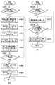
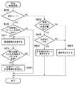
次に、図3を参照して、第1の実施形態に係る、表示装置100及び撮像装置200の動作について説明する。図3(a)は、表示装置100に関し、図3(b)は、撮像装置200に関する。図3(a)に示すフローチャートの各ステップの処理は、特に断らない限り、制御部5がROMに格納された制御プログラムをRAMに展開して実行して表示装置100の各ブロックを制御することにより実現される。同様に、図3(b)に示すフローチャートの各ステップの処理は、特に断らない限り、制御部8がROMに格納された制御プログラムをRAMに展開して実行して撮像装置200の各ブロックを制御することにより実現される。これは、後述する図4(a)及び図4(b)においても同様である。 Next, operations of the
最初に、図3(a)に示される表示装置100の動作について説明する。S301で、表示装置100の制御部5は、ユーザによる角度補正モードへの移行指示が行われたか否かを判定する。角度補正モードへの移行指示が行われていない場合、本フローチャートの処理は終了する。角度補正モードへの移行指示が行われた場合、処理はS302に進む。 First, the operation of the
S302で、制御部5は、通信処理部1を介して、撮像装置200が撮像した撮像画像、及び撮像装置200の水平情報を受信する(図2(b)参照)。S303で、表示処理部3は、S302において受信した撮像装置200の撮像画像を表示部2に表示する。また、表示処理部3は、水平情報に基づいて水平線の画像を生成し、表示部2に表示された撮像画像に対して水平線を重畳表示する(図2(b)参照)。 In S302, the
S304で、制御部5は、角度検出部4から出力される角度情報を検出する。ここでの角度情報は、表示部2の表示画面に直交する回転軸の周りでの回転角度を示す(図9(a)の回転軸901参照)。S305で、制御部5は、S304において検出された角度情報に基づき、ユーザが撮像画像を補正する際の目安となる、表示装置100側で検出された水平方向を確認するためのグリッド状の補助線を生成する。そして、表示処理部3は、表示部2に表示された撮像画像に対して、補助線を重畳表示する。図2(c)に示すように、このグリッド状の補助線の横線(水平補助線)は、表示装置100の回転角度を変更しても、常に水平を保つ(表示装置100側で検出された水平方向と平行になる)ように表示される。ユーザは、水平補助線と撮影している被写体の水平部分(例えば、図2(b)及び図2(c)に示す被写体補助線H)とが一致するように表示装置100の回転角度を調整する。これにより、ユーザは容易に被写体を水平に撮影するための補正情報を生成することが可能である。 In S <b> 304, the
S306で、表示処理部3は、表示装置100の回転角度に応じた補正を行う場合における撮像画像の切り出しサイズを示す情報(切り出し枠)を表示部2に表示する(図2(c)参照)。切り出しサイズは、図2(c)を参照して前述した通り、角度検出部4で検出した角度情報に基づき制御部5により算出される。回転角度、即ち補正量が大きくなると、切り出しサイズが小さくなるが、ユーザは、切り出し枠を見ることにより、撮像画像がどの程度小さくなるかを確認しながら表示装置100を回転させることができる。 In step S <b> 306, the
S307で、制御部5は、ユーザによる角度補正モードの終了指示が行われたか否かを判定する。角度補正モードの終了指示が行われていない場合、処理はS302に戻り、同様の処理が繰り返される。角度補正モードの終了指示が行われた場合、処理はS308に進む。 In S307, the
S308で、制御部5は、撮像装置200に対する回転指示コマンドを生成する。回転指示コマンドには、撮像装置200が電子的な画像補正を行うための角度情報が含まれる。例えば、角度検出部4で検出した重力方向を示す情報、あるいは表示部2の表示面に直行する軸を回転軸とした重力方向に対する角度(向き)に関する情報を含むものとする。S309で、制御部5は、通信処理部1を介して、撮像装置200に回転指示コマンドを送信し、本フローチャートの処理は終了する。その後、撮像装置200から、回転指示コマンドに応じて補正された撮像画像を受信し、表示部2に表示することができる。これによって、表示装置100のユーザは、意図通りの向きに補正されたかどうかを確認することができ、必要に応じて再度角度補正モードにして補正作業を行うことができる。 In S <b> 308, the
次に、図3(b)に示される撮像装置200の動作について説明する。S310で、撮像装置200の制御部8は、ユーザによる角度補正モードへの移行指示が行われたか否かを判定する。ここでの移行指示は、例えば、表示装置100を介して遠隔的に行われる。角度補正モードへの移行指示が行われていない場合、本フローチャートの処理は終了する。角度補正モードへの移行指示が行われた場合、処理はS311に進む。 Next, the operation of the
S311で、制御部8は、通信処理部9を介して、撮像画像を表示装置100に送信する。また、水平検出部13で検出された、撮像装置200の姿勢を示す前述の水平情報を表示装置100に送信する。S312で、制御部8は、表示装置100から回転指示コマンドを受信したか否かを判定する。回転指示コマンドを受信していない場合、処理はS311に戻り、同様の処理が繰り返される。これらの処理は、表示装置100側で撮像画像がライブビューとして視認できるように、所定のフレームレート毎(例えば30fps)に繰り返される。回転指示コマンドを受信した場合、処理はS313に進む。 In S <b> 311, the control unit 8 transmits the captured image to the
S313で、画像処理部7は、回転指示コマンドに含まれる角度情報に基づいて電子的に画像処理を行うことで、撮像画像の傾きを補正する。傾きを補正した撮像画像は、表示装置100側でのレビューのために、表示装置100に送信する。また、回転指示コマンドに含まれる角度情報を含む補正のための情報を、撮像装置200のROMまたはRAMに保持(記録)し、本フローチャートの処理は終了する。この後に撮像装置200で静止画又は動画を撮像して記録又は送信する際には、画像処理部7は、保持した情報(回転指示コマンドに含まれる角度情報を含む補正のための情報)に基づいて補正を行う。そして、補正した撮像画像を静止画または動画として記録部10に記録する、あるいは通信処理部9を介して送信する。すなわち、回転指示コマンドを受信した後に撮像された複数の画像に対して、保持した情報に基づいた補正を行うこととなる。 In S313, the
以上の処理により、図2(b)に示すように傾いていた撮像画像が、図2(c)に示すように、表示装置100の回転角度に応じて補正される。 Through the above processing, the captured image tilted as shown in FIG. 2B is corrected according to the rotation angle of the
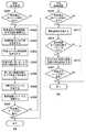
ところで、図3のフローチャートでは、表示装置100は、S307において角度補正モードの終了指示が行われた後に、撮像装置200に回転指示コマンドを送信している。これによって、一度補正角度を調整して角度補正モードを終了すると、その後撮影された画像に同じ補正を繰り返し適用することができる。一方、図4に示すように、表示装置100は、角度補正モードの終了指示を待たずに、リアルタイムに回転指示コマンドを生成して撮像装置200へ送信してもよい。これにより、撮像装置200は、表示装置100の回転に追従して撮像画像を補正することができる。図4(a)及び図4(b)は、それぞれ図3(a)及び図3(b)に対応し、図3(a)及び図3(b)と同一又は同様の処理が行われるステップには、同一の符号が付されている。図4(a)は、S308及びS309がS307の手前に移動したことを除き、図3(a)と同じである。また、図4(b)は、S313の後にS401が追加されたことを除き、図3(b)と同じである。S401において、制御部8は、ユーザによる角度補正モードの終了指示が行われたか否かを判定する。ここでの終了指示は、例えば、表示装置100を介して遠隔的に行われる。角度補正モードの終了指示が行われていない場合、処理はS311に戻り、同様の処理が繰り返される。角度補正モードの終了指示が行われた場合、回転指示コマンドに含まれる角度情報を含む補正のための情報を、撮像装置200のROMまたはRAMに保持(記録)し、本フローチャートの処理は終了する。この後に撮像装置200で静止画又は動画を撮像して記録又は送信する際には、画像処理部7は、保持した情報(回転指示コマンドに含まれる角度情報を含む補正のための情報)に基づいて補正を行う。そして、補正した撮像画像を静止画または動画として記録部10に記録する、あるいは通信処理部9を介して送信する。 Incidentally, in the flowchart of FIG. 3, the
以上説明したように、第1の実施形態によれば、表示装置100は、撮像装置200から受信した撮像画像を表示部2に表示する。そして、表示装置100は、表示装置100の回転角度(表示部2の表示画面に直交する回転軸の周りでの回転角度)を示す角度情報を撮像装置200へ送信する。撮像装置200は、角度情報に従い、撮像画像の傾きを補正する。 As described above, according to the first embodiment, the
これにより、撮像装置から撮像画像を受信して表示する表示装置のユーザが撮像画像を直感的に補正することが可能となる。 Thereby, a user of a display device that receives and displays a captured image from the imaging device can intuitively correct the captured image.
[第2の実施形態]
第1の実施形態では、表示装置100の回転角度を示す角度情報を用いることで撮像装置200の撮像画像の傾きを電子的に補正する構成について説明した。第2の実施形態では、ユーザが表示装置100を前後に傾けることで、撮像画像のあおりを補正する構成について説明する。第2の実施形態における表示装置100及び撮像装置200の基本的な構成は、図1に示した第1の実施形態と同様であるため、構成についての詳細な説明は省略する。以下、主に第1の実施形態と異なる点について説明する。[Second Embodiment]
In the first embodiment, the configuration in which the inclination of the captured image of the
最初に、図5を参照して、第2の実施形態の概要について説明する。第2の実施形態は、表示装置100の角度に応じて撮像画像を補正するという点では、第1の実施形態と同様である。但し、第2の実施形態における「表示装置100の角度」は、表示装置100の前後の傾き角度(より厳密には、表示部2の表示画面の前後の傾き角度に対応する。ここで言う「前後の傾き」は、表示部2の表示画面と同一平面内にある、表示画面の横線と平行な回転軸における、表示画面の回転に対応する(図9(b)の回転軸902参照)。また、例えば、図9(b)の右側に示すように表示画面の縦線(上下の線)が地面に対して垂直な場合の傾き角度を0度と定義する。ここで、表示画面(又は表示装置100)にとって「地面に対して垂直」な方向は、表示装置100の角度検出部4により検出される重力方向を意味する。図5(c)に示すように、表示装置100は、角度情報を含むあおり指示コマンドを撮像装置200へ送信する。撮像装置200は、角度情報に従って撮像画像を補正することにより、あおりを補正する。 First, the outline of the second embodiment will be described with reference to FIG. The second embodiment is the same as the first embodiment in that the captured image is corrected according to the angle of the
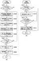
次に、図6を参照して、第2の実施形態に係る、表示装置100及び撮像装置200の動作について説明する。図6(a)は、表示装置100に関し、図6(b)は、撮像装置200に関する。図6(a)及び図6(b)において、図3(a)及び図3(b)と同一又は同様の処理が行われるステップには、同一の符号を付す。図6(a)に示すフローチャートの各ステップの処理は、特に断らない限り、制御部5がROMに格納された制御プログラムをRAMに展開して実行して表示装置100の各ブロックを制御することにより実現される。同様に、図6(b)に示すフローチャートの各ステップの処理は、特に断らない限り、制御部8がROMに格納された制御プログラムをRAMに展開して実行して撮像装置200の各ブロックを制御することにより実現される。 Next, operations of the
最初に、図6(a)に示される表示装置100の動作について説明する。S604で、制御部5は、角度検出部4から出力される角度情報を検出する。ここでの角度情報は、表示部2の表示画面の前後の傾き角度を示す(図9(b)の回転軸902参照)。 First, the operation of the
S605で、制御部5は、S604において検出された角度情報に基づき、ユーザが撮像画像を補正する際の目安となる補助情報を算出する。本実施形態では、補助情報は、グリッド状の補助線であり、とりわけ、2つの垂直補助線を含むものとする。そして、表示処理部3は、表示部2に表示された撮像画像に対して、補助線を重畳表示する。図5(c)に示すように、2つの垂直補助線は、表示装置100の傾き角度に応じて傾き(角度)が変化し、上部と下部とで間隔が異なる。表示装置100の傾き角度が基準値(例えば、図5(b)に示す角度)の場合、2つの垂直補助線は、表示画面の縦方向と平行になるように表示される。すなわち、2つの垂直補助線が平行に表示される。また、表示装置100の上部が奥へ振られた場合は、2つの垂直補助線の上部の間隔が狭く、下部の間隔が広くなる。また、表示装置100の上部が手前へ振られた場合は、2つの垂直補助線の上部の間隔が広く、下部の間隔が狭くなる。ユーザは、これら2つの垂直補助線が被写体に対して垂直に補正したい角度になるまで、表示装置100を前後に傾ける。図5(b)及び図5(c)の例では、ユーザは、被写体垂直線Vと垂直補助線とが平行になるように、表示装置100を前後に傾ける。なお、被写体の種類によっては被写体垂直線Vに相当するものが存在しない場合もあるが、この場合でも、ユーザは、表示装置100を回転させて被写体の所望の部分が垂直補助線と成す角度を調節することにより、撮像画像を補正することができる。 In step S <b> 605, the
S608及びS609の処理は、コマンドが「あおり指示コマンド」である点を除き、図3のS308及びS309の処理と同様である。あおり指示コマンドに含まれる角度情報は、例えば、角度検出部4で検出した重力方向を示す情報、あるいは表示部2の表示面の重力方向に対する角度(向き)に関する情報を含むものとする。その後、撮像装置200から、あおり指示コマンドに応じて補正された撮像画像を受信し、表示部2に表示することができる。これによって、表示装置100のユーザは、意図通りにあおり補正されたかどうかを確認することができ、必要に応じて再度角度補正モードにして補正作業を行うことができる。 The processing of S608 and S609 is the same as the processing of S308 and S309 in FIG. 3 except that the command is an “tilting instruction command”. The angle information included in the tilt instruction command includes, for example, information indicating the direction of gravity detected by the
次に、図6(b)に示される撮像装置200の動作について説明する。S612の処理は、コマンドが「あおり指示コマンド」である点を除き、図3のS312の処理と同様である。S613で、画像処理部7は、あおり指示コマンドに含まれる角度情報に基づいて電子的に画像処理を行うことで、撮像画像のあおりを補正する。傾きを補正した撮像画像は、表示装置100側でのレビューのために、表示装置100に送信する。また、あおり指示コマンドに含まれる角度情報を含む補正のための情報を、撮像装置200のROMまたはRAMに保持(記録)し、本フローチャートの処理は終了する。この後に撮像装置200で静止画又は動画を撮像して記録又は送信する際には、画像処理部7は、保持した情報(あおり指示コマンドに含まれる角度情報を含む補正のための情報)に基づいて補正を行う。そして、補正した撮像画像を静止画または動画として記録部10に記録する、あるいは通信処理部9を介して送信する。すなわち、あおり指示コマンドを受信した後に撮像された複数の画像に対して、保持した情報に基づいた補正を行うこととなる。 Next, the operation of the
以上説明したように、第2の実施形態によれば、表示装置100は、撮像装置200から受信した撮像画像を表示部2に表示し、表示装置100の傾き角度(表示部2の表示画面の前後の傾き角度)を示す角度情報を撮像装置200へ送信する。撮像装置200は、角度情報に従い、撮像画像のあおりを補正する。これにより、ユーザが撮像画像のあおりを直感的に補正することが可能となる。 As described above, according to the second embodiment, the
なお、第1の実施形態で説明した撮像画像の回転補正の実施形態と、第2の実施形態で説明した撮像画像のあおり補正の実施形態は同時に実施することも可能である。その場合、表示部2で表示する補助線のうち、水平補助線は第1の実施形態で説明したものと同様の表示装置100側で検出した水平方向を示す補助線となり、垂直補助線は第2の実施形態で説明したものと同様の表示装置100の前後の傾き(重力方向に対する表示面の角度)を示す補助線となる。そして、表示装置100から撮像装置200に送信する角度情報は撮像画像の回転補正及びあおり補正の双方に必要な情報を含む。また、撮像装置200は表示装置100から受信した回転指示及びあおり指示のコマンドに含まれる角度情報に基づいて、回転補正とあおり補正の双方を行う。 It should be noted that the captured image rotation correction embodiment described in the first embodiment and the captured image tilt correction embodiment described in the second embodiment can be performed simultaneously. In this case, among the auxiliary lines displayed on the
[第3の実施形態]
第1及び第2の実施形態では、撮像装置200の撮像画像の傾き又はあおりを撮影時に補正する構成について説明した。第3の実施形態では、角度情報を画像ファイルに書き込むことで、再生時、又は、後処理による画像処理時に補正を行う構成について説明する。第3の実施形態における表示装置100及び撮像装置200の基本的な構成は、図1に示した第1の実施形態と同様であるため、構成についての詳細な説明は省略する。以下、主に第1の実施形態と異なる点について説明する。なお、本実施形態は、撮像画像の傾きを補正する文脈で説明するが、撮像画像のあおりを補正する場合(即ち、第2の実施形態の文脈)にも同様に適用可能である。[Third Embodiment]
In the first and second embodiments, the configuration in which the tilt or tilt of the captured image of the
最初に、図7を参照して、第3の実施形態の概要について説明する。第3の実施形態は、表示装置100が撮像装置200に対して角度情報を含む回転指示コマンドを送信するという点では、第1の実施形態と同様である(図7(a)参照)。但し、図7(b)に示すように、撮像装置200は、回転指示コマンドに応えて撮像画像を補正するのではなく、撮像画像の画像ファイルの中に角度情報を書き込む。撮像装置200は、画像ファイルの再生時に、角度情報に従って画像の補正を行う。即ち、撮像装置200は、撮像画像を角度情報に関連付けて記録する。また、ユーザは、操作部11を介して、角度情報に従う画像補正を行うか否かを撮像装置200に指示することができる。 First, the outline of the third embodiment will be described with reference to FIG. The third embodiment is the same as the first embodiment in that the
次に、図8を参照して、第3の実施形態に係る、撮像装置200の動作について説明する。表示装置100の動作については、第1の実施形態と同様である(図3(a)参照)。図8において、図3(b)と同一又は同様の処理が行われるステップには、同一の符号を付す。図8に示すフローチャートの各ステップの処理は、特に断らない限り、制御部8がROMに格納された制御プログラムをRAMに展開して実行して撮像装置200の各ブロックを制御することにより実現される。 Next, the operation of the
S810で、撮像装置200の制御部8は、撮像装置200の現在の動作モードが撮影モードであるか否かを判定する。撮影モードの場合、処理はS310に進む。S310〜S312の処理に続き、S811で、制御部8は、記録部10を介して、撮像画像を画像ファイルとして記録すると共に、角度情報を画像ファイルに書き込む。 In S810, the control unit 8 of the
一方、S810において撮像装置200の動作モードが撮影モードでない(再生モードである)と判定された場合、処理はS812に進む。S812で、制御部8は、再生対象の画像ファイルの中に角度情報が含まれているか否かを判定する。画像ファイルの中に角度情報が含まれている場合、処理はS813に進み、そうでない場合、処理はS815に進む。 On the other hand, if it is determined in S810 that the operation mode of the
S813で、制御部8は、角度情報に基づく補正処理がONになっているか否かを判定する。補正処理のON/OFFは、ユーザが操作部11を介して切り替えることができる。補正処理がONになっている場合、処理はS814に進み、そうでない場合、処理はS815に進む。 In step S813, the control unit 8 determines whether correction processing based on the angle information is ON. The user can switch the correction process ON / OFF via the
S814で、画像処理部7は、画像ファイル中の画像を角度情報に従って補正し、補正後の画像を表示部12に表示する。ここでの画像は、例えば、動画である。一方、画像ファイルに角度情報が含まれていない場合、又は補正処理がOFFの場合は、S815で、画像処理部7は、補正を行わずに通常再生を行う。 In S814, the
以上の処理を行うことにより、撮影時ではなく再生時に撮像装置200の撮像画像の傾きを補正することが可能となる。このように、撮像画像の記録と同時に補正情報(角度情報)を記録することにより、再生時のみではなく、後処理として画像補正ツールを用いて傾き補正を行うこともできる。これにより、ユーザは、補正の有無を撮影後に決定できるだけでなく、補正による撮像画像の切り出しサイズの縮小とのトレードオフを考慮して、補正を行うか否かを決定することが可能になる。 By performing the above processing, it is possible to correct the inclination of the captured image of the
なお、表示装置100及び撮像装置200の制御は1つのハードウェアが行ってもよいし、複数のハードウェアが処理を分担することで、装置全体の制御を行ってもよい。 Note that the
また、本発明をその好適な実施形態に基づいて詳述してきたが、本発明はこれら特定の実施形態に限られるものではなく、この発明の要旨を逸脱しない範囲の様々な形態も本発明に含まれる。さらに、上述した各実施形態は本発明の一実施形態を示すものにすぎず、各実施形態を適宜組み合わせることも可能である。 Although the present invention has been described in detail based on the preferred embodiments thereof, the present invention is not limited to these specific embodiments, and various forms without departing from the gist of the present invention are also included in the present invention. included. Furthermore, each embodiment mentioned above shows only one embodiment of this invention, and it is also possible to combine each embodiment suitably.
また、上述した実施形態においては、本発明をスマートフォンのような表示装置、及びデジタルカメラのような撮像装置に適用した場合を例にして説明したが、これはこの例に限定されない。本発明は、撮像画像を受信して表示する装置、及び、画像を撮像して送信する装置であれば、任意の種類の装置に適用可能である。即ち、本発明は、パーソナルコンピュータやPDA、携帯電話端末や携帯型の画像ビューワ、ディスプレイを備えるプリンタ装置、デジタルフォトフレーム、音楽プレーヤー、ゲーム機、電子ブックリーダーなどに適用可能である。 In the above-described embodiment, the case where the present invention is applied to a display device such as a smartphone and an imaging device such as a digital camera has been described as an example. However, this is not limited to this example. The present invention is applicable to any type of device as long as it is a device that receives and displays a captured image and a device that captures and transmits an image. That is, the present invention can be applied to a personal computer, a PDA, a mobile phone terminal, a portable image viewer, a printer device including a display, a digital photo frame, a music player, a game machine, an electronic book reader, and the like.
[その他の実施形態]
また、本発明は、以下の処理を実行することによっても実現される。即ち、上述した実施形態の機能を実現するソフトウェア(プログラム)を、ネットワーク又は各種記憶媒体を介してシステム或いは装置に供給し、そのシステム或いは装置のコンピュータ(又はCPUやMPU等)がプログラムを読み出して実行する処理である。[Other Embodiments]
The present invention can also be realized by executing the following processing. That is, software (program) that realizes the functions of the above-described embodiments is supplied to a system or apparatus via a network or various storage media, and a computer (or CPU, MPU, etc.) of the system or apparatus reads the program. It is a process to be executed.
1…通信処理部、2…表示部、3…表示処理部、4…角度検出部、5…制御部、6…撮像処理部、7…画像処理部、8…制御部、9…通信処理部、10…記録部、11…操作部、12…表示部、13…水平検出部、100…表示装置、200…撮像装置 DESCRIPTION OF SYMBOLS 1 ... Communication processing part, 2 ... Display part, 3 ... Display processing part, 4 ... Angle detection part, 5 ... Control part, 6 ... Imaging processing part, 7 ... Image processing part, 8 ... Control part, 9 ... Communication processing part DESCRIPTION OF
Claims (25)
Translated fromJapanese撮像装置から撮像画像を受信する受信手段と、
前記撮像画像を表示する表示手段と、
前記表示装置の姿勢を検出する検出手段と、
前記表示手段での前記撮像画像の表示中に前記検出手段により検出された姿勢を示す姿勢情報を前記撮像装置へ送信する送信手段と、
を備えることを特徴とする表示装置。A display device,
Receiving means for receiving a captured image from the imaging device;
Display means for displaying the captured image;
Detecting means for detecting an attitude of the display device;
Transmitting means for transmitting attitude information indicating the attitude detected by the detecting means during display of the captured image on the display means to the imaging device;
A display device comprising:
ことを特徴とする請求項1に記載の表示装置。The display device according to claim 1, wherein the display unit displays auxiliary information indicating the posture detected by the detection unit together with the captured image.
ことを特徴とする請求項2に記載の表示装置。The auxiliary information includes a horizontal auxiliary line indicating a horizontal line perpendicular to the direction of gravity in the display device according to a rotation angle of the display device on a rotation axis orthogonal to a display surface of the display means. Item 3. The display device according to Item 2.
前記表示手段の上部が奥へ傾くほど、前記2つの補助線の上部の間隔に比べて下部の間隔が広くなり、
前記表示手段の上部が手前へ傾くほど、前記2つの垂直補助線の上部の間隔に比べて下部の間隔が狭くなる
ことを特徴とする請求項2又は3に記載の表示装置。The auxiliary information includes two auxiliary lines displayed so as to be parallel to the vertical direction of the display means when the tilt angle of the display device is a reference value,
As the upper part of the display means is tilted to the back, the distance between the lower parts is wider than the distance between the two auxiliary lines.
4. The display device according to claim 2, wherein as the upper portion of the display unit is tilted toward the front, the lower interval is narrower than the upper interval between the two vertical auxiliary lines. 5.
ことを特徴とする請求項1乃至6のいずれか1項に記載の表示装置。The display means displays, together with the captured image, information indicating a partial region cut out from the captured image when the captured image is subjected to rotation correction or tilt correction based on the posture detected by the detection means. The display device according to any one of claims 1 to 6.
前記表示手段は、前記撮像装置姿勢情報に基づき、前記撮像装置における水平方向を示す情報を前記撮像画像とともに表示する
ことを特徴とする請求項1乃至7のいずれか1項に記載の表示装置。The receiving unit receives imaging apparatus attitude information indicating an attitude of the imaging apparatus;
The display device according to claim 1, wherein the display unit displays information indicating a horizontal direction in the imaging device together with the captured image based on the imaging device attitude information.
ことを特徴とする請求項1乃至8のいずれか1項に記載の表示装置。The display device according to any one of claims 1 to 8, wherein the display device is a portable terminal that can be held by a user.
前記表示手段は前記補正された撮像画像を表示することを特徴とする請求項1乃至10のいずれか1項に記載の表示装置。The receiving means receives the captured image corrected based on the posture information after transmitting the posture information to the imaging device;
The display device according to claim 1, wherein the display unit displays the corrected captured image.
前記撮像画像を表示装置へ送信する送信手段と、
前記表示装置の姿勢を示す姿勢情報を前記表示装置から受信する受信手段と、
前記受信手段により受信された姿勢情報に基づいて、撮像画像に対して特定の処理を行う処理手段と、
を備えることを特徴とする撮像装置。An imaging means for generating a captured image;
Transmitting means for transmitting the captured image to a display device;
Receiving means for receiving posture information indicating the posture of the display device from the display device;
Processing means for performing specific processing on the captured image based on the posture information received by the receiving means;
An imaging apparatus comprising:
ことを特徴とする請求項12に記載の撮像装置。The imaging apparatus according to claim 12, wherein the specific processing includes rotation correction or tilt correction of the captured image based on the posture information.
ことを特徴とする請求項12又は13に記載の撮像装置。The imaging apparatus according to claim 12 or 13, wherein the specific process includes a process of recording the posture information in association with the captured image.
前記処理手段は、前記再生手段による前記撮像画像の再生時に、前記撮像画像に関連付けられた姿勢情報に基づいて前記撮像画像に回転補正又はあおり補正を行うことを特徴とする請求項14に記載の撮像装置。Replaying means for replaying a captured image recorded in association with the posture information by the processing means;
15. The processing unit according to claim 14, wherein the processing unit performs rotation correction or tilt correction on the captured image based on posture information associated with the captured image when the captured unit reproduces the captured image. Imaging device.
ことを特徴とする請求項12乃至15のいずれか1項に記載の撮像装置。The posture information includes information indicating a gravitational direction detected by the display device or information regarding an angle with respect to a gravitational direction with an axis orthogonal to a display surface of a display unit of the display device as a rotation axis. Item 16. The imaging device according to any one of Items 12 to 15.
ことを特徴とする請求項12乃至16のいずれか1項に記載の撮像装置。The posture information includes information indicating a gravity direction detected by the display device, or information on an angle of the display surface of the display device with respect to the gravity direction of the display unit. The imaging device according to item.
前記処理手段は、前記姿勢情報を受信した後に撮像された複数の画像に対して、前記保持手段に保持された前記情報に基づいて前記特定の処理を施すことを特徴とする請求項12乃至17のいずれか1項に記載の撮像装置。Further comprising holding means for holding information for performing the specific processing based on the posture information received by the receiving means;
18. The processing unit performs the specific process on a plurality of images captured after receiving the posture information based on the information held in the holding unit. The imaging device according to any one of the above.
前記表示装置は、
前記撮像装置から撮像画像を受信する受信手段と、
前記撮像画像を表示する表示手段と、
前記表示装置の姿勢を検出する検出手段と、
前記表示手段での前記撮像画像の表示中に前記検出手段により検出された姿勢を示す姿勢情報を前記撮像装置へ送信する送信手段と、
を備え、
前記撮像装置は、
撮像画像を生成する撮像手段と、
前記撮像画像を前記表示装置へ送信する送信手段と、
前記表示装置の姿勢を示す姿勢情報を前記表示装置から受信する受信手段と、
前記撮像装置の前記受信手段により受信された姿勢情報に基づいて、撮像画像に対して特定の処理を行う処理手段と、
を備える
ことを特徴とする撮像システム。An imaging system including a display device and an imaging device,
The display device
Receiving means for receiving a captured image from the imaging device;
Display means for displaying the captured image;
Detecting means for detecting an attitude of the display device;
Transmitting means for transmitting attitude information indicating the attitude detected by the detecting means during display of the captured image on the display means to the imaging device;
With
The imaging device
An imaging means for generating a captured image;
Transmitting means for transmitting the captured image to the display device;
Receiving means for receiving posture information indicating the posture of the display device from the display device;
Processing means for performing specific processing on the captured image based on the posture information received by the receiving means of the imaging device;
An imaging system comprising:
撮像装置から撮像画像を受信する受信工程と、
前記撮像画像を前記表示手段に表示する表示工程と、
前記姿勢検出手段で前記表示装置の姿勢を検出する検出工程と、
前記表示工程による前記撮像画像の表示中に前記検出工程により検出された姿勢を示す姿勢情報を前記撮像装置へ送信する送信工程と、
を備えることを特徴とする表示装置の制御方法。A control method of a display device having a display means and a posture detection means,
A receiving step of receiving a captured image from the imaging device;
A display step of displaying the captured image on the display means;
A detection step of detecting the posture of the display device by the posture detection means;
A transmission step of transmitting posture information indicating the posture detected by the detection step during display of the captured image by the display step to the imaging device;
A control method for a display device, comprising:
撮像画像を生成する撮像工程と、
前記撮像画像を表示装置へ送信する送信工程と、
前記表示装置の姿勢を示す姿勢情報を前記表示装置から受信する受信工程と、
前記受信工程により受信された姿勢情報に基づいて、撮像画像に対して特定の処理を行う処理工程と、
を備えることを特徴とする撮像装置の制御方法。A method for controlling an imaging apparatus,
An imaging process for generating a captured image;
A transmission step of transmitting the captured image to a display device;
A receiving step of receiving posture information indicating the posture of the display device from the display device;
A processing step for performing a specific process on the captured image based on the posture information received by the reception step;
An image pickup apparatus control method comprising:
Priority Applications (2)
| Application Number | Priority Date | Filing Date | Title |
|---|---|---|---|
| JP2015003604AJP6518069B2 (en) | 2015-01-09 | 2015-01-09 | Display device, imaging system, display device control method, program, and recording medium |
| US14/990,176US9924086B2 (en) | 2015-01-09 | 2016-01-07 | Display apparatus, image capturing system, control method for display apparatus, and storage medium for displaying information based on attitude |
Applications Claiming Priority (1)
| Application Number | Priority Date | Filing Date | Title |
|---|---|---|---|
| JP2015003604AJP6518069B2 (en) | 2015-01-09 | 2015-01-09 | Display device, imaging system, display device control method, program, and recording medium |
Publications (3)
| Publication Number | Publication Date |
|---|---|
| JP2016129315Atrue JP2016129315A (en) | 2016-07-14 |
| JP2016129315A5 JP2016129315A5 (en) | 2018-02-08 |
| JP6518069B2 JP6518069B2 (en) | 2019-05-22 |
Family
ID=56368421
Family Applications (1)
| Application Number | Title | Priority Date | Filing Date |
|---|---|---|---|
| JP2015003604AActiveJP6518069B2 (en) | 2015-01-09 | 2015-01-09 | Display device, imaging system, display device control method, program, and recording medium |
Country Status (2)
| Country | Link |
|---|---|
| US (1) | US9924086B2 (en) |
| JP (1) | JP6518069B2 (en) |
Cited By (20)
| Publication number | Priority date | Publication date | Assignee | Title |
|---|---|---|---|---|
| JP2021051752A (en)* | 2019-05-06 | 2021-04-01 | アップル インコーポレイテッドApple Inc. | User interfaces for capturing and managing visual media |
| US11112964B2 (en) | 2018-02-09 | 2021-09-07 | Apple Inc. | Media capture lock affordance for graphical user interface |
| US11128792B2 (en) | 2018-09-28 | 2021-09-21 | Apple Inc. | Capturing and displaying images with multiple focal planes |
| US11165949B2 (en) | 2016-06-12 | 2021-11-02 | Apple Inc. | User interface for capturing photos with different camera magnifications |
| US11178335B2 (en) | 2018-05-07 | 2021-11-16 | Apple Inc. | Creative camera |
| US11204692B2 (en) | 2017-06-04 | 2021-12-21 | Apple Inc. | User interface camera effects |
| US11212449B1 (en) | 2020-09-25 | 2021-12-28 | Apple Inc. | User interfaces for media capture and management |
| US11223771B2 (en) | 2019-05-06 | 2022-01-11 | Apple Inc. | User interfaces for capturing and managing visual media |
| US11321857B2 (en) | 2018-09-28 | 2022-05-03 | Apple Inc. | Displaying and editing images with depth information |
| US11330184B2 (en) | 2020-06-01 | 2022-05-10 | Apple Inc. | User interfaces for managing media |
| US11350026B1 (en) | 2021-04-30 | 2022-05-31 | Apple Inc. | User interfaces for altering visual media |
| US11490017B2 (en) | 2015-04-23 | 2022-11-01 | Apple Inc. | Digital viewfinder user interface for multiple cameras |
| US11706521B2 (en) | 2019-05-06 | 2023-07-18 | Apple Inc. | User interfaces for capturing and managing visual media |
| US11722764B2 (en) | 2018-05-07 | 2023-08-08 | Apple Inc. | Creative camera |
| US11770601B2 (en) | 2019-05-06 | 2023-09-26 | Apple Inc. | User interfaces for capturing and managing visual media |
| US11778339B2 (en) | 2021-04-30 | 2023-10-03 | Apple Inc. | User interfaces for altering visual media |
| JP2024099555A (en)* | 2018-07-17 | 2024-07-25 | インターディジタル・シーイー・パテント・ホールディングス・ソシエテ・パ・アクシオンス・シンプリフィエ | DEVICE AND METHOD FOR DISPLAYING IMAGES - Patent application |
| US12112024B2 (en) | 2021-06-01 | 2024-10-08 | Apple Inc. | User interfaces for managing media styles |
| US12154218B2 (en) | 2018-09-11 | 2024-11-26 | Apple Inc. | User interfaces simulated depth effects |
| US12401889B2 (en) | 2023-05-05 | 2025-08-26 | Apple Inc. | User interfaces for controlling media capture settings |
Families Citing this family (12)
| Publication number | Priority date | Publication date | Assignee | Title |
|---|---|---|---|---|
| US10007476B1 (en)* | 2014-03-23 | 2018-06-26 | Kevin Glikmann | Sharing a host mobile camera with a remote mobile device |
| CN104994273A (en)* | 2015-06-16 | 2015-10-21 | 成都西可科技有限公司 | System of maintaining real-time shooting image to be vertical and method thereof |
| JP6644641B2 (en)* | 2016-05-31 | 2020-02-12 | オリンパス株式会社 | Imaging device, control method, and program |
| CN107710283B (en) | 2016-12-02 | 2022-01-28 | 深圳市大疆创新科技有限公司 | Shooting control method and device and control equipment |
| JP7179446B2 (en)* | 2017-05-22 | 2022-11-29 | キヤノン株式会社 | Information processing device, information processing method, and program |
| US10668883B2 (en)* | 2017-06-08 | 2020-06-02 | Gentex Corporation | Display device with level correction |
| US20190297265A1 (en)* | 2018-03-21 | 2019-09-26 | Sawah Innovations Inc. | User-feedback video stabilization device and method |
| EP3853262A4 (en)* | 2018-09-19 | 2022-03-30 | Conagen Inc. | CONTROLLABLE PROTEIN DEGRADATION BY ENGINEERING DEGRADATION TAG VARIANTS IN CORYNEBACTERIUM HOST CELLS |
| EP3644600B1 (en)* | 2018-10-22 | 2022-06-15 | Ricoh Company, Ltd. | Imaging device, information processing method, system, and carrier means |
| US10897573B2 (en)* | 2018-11-21 | 2021-01-19 | Ricoh Company, Ltd. | Image capturing system, terminal and computer readable medium which correct images |
| WO2022040951A1 (en)* | 2020-08-26 | 2022-03-03 | 深圳市大疆创新科技有限公司 | Image correction method and device, image collecting device, and storage medium |
| JP7703377B2 (en)* | 2021-06-21 | 2025-07-07 | キヤノン株式会社 | Imaging device, information processing device, and control method and program thereof |
Citations (7)
| Publication number | Priority date | Publication date | Assignee | Title |
|---|---|---|---|---|
| JP2002271654A (en)* | 2001-03-12 | 2002-09-20 | Fuji Photo Film Co Ltd | Electronic camera |
| JP2004194168A (en)* | 2002-12-13 | 2004-07-08 | Fuji Photo Film Co Ltd | Trimming processor and trimming processing program |
| JP2005175813A (en)* | 2003-12-10 | 2005-06-30 | Sony Corp | Electronic equipment, image information transmission system and method |
| JP2005348212A (en)* | 2004-06-04 | 2005-12-15 | Casio Comput Co Ltd | Imaging device |
| US20130027570A1 (en)* | 2011-07-29 | 2013-01-31 | Canon Kabushiki Kaisha | Display control system, display control apparatus and control method therefor |
| JP2013162277A (en)* | 2012-02-03 | 2013-08-19 | Nikon Corp | Digital camera |
| US20140270692A1 (en)* | 2013-03-18 | 2014-09-18 | Nintendo Co., Ltd. | Storage medium storing information processing program, information processing device, information processing system, panoramic video display method, and storage medium storing control data |
Family Cites Families (20)
| Publication number | Priority date | Publication date | Assignee | Title |
|---|---|---|---|---|
| US4967278A (en)* | 1988-08-08 | 1990-10-30 | Steve Greenbaum | Video camera with a transverse tilt detector and indicator comprising an ordered array of light-emitting diodes |
| US5790085A (en)* | 1994-10-19 | 1998-08-04 | Raytheon Company | Portable interactive heads-up weapons terminal |
| US6968094B1 (en)* | 2000-03-27 | 2005-11-22 | Eastman Kodak Company | Method of estimating and correcting camera rotation with vanishing point location |
| US7554578B2 (en)* | 2000-07-11 | 2009-06-30 | Phase One A/S | Digital camera with integrated accelerometers |
| US6963365B2 (en)* | 2001-02-28 | 2005-11-08 | Hewlett-Packard Development Company, L.P. | System and method for removal of digital image vertical distortion |
| US6917370B2 (en)* | 2002-05-13 | 2005-07-12 | Charles Benton | Interacting augmented reality and virtual reality |
| KR100595617B1 (en)* | 2003-11-29 | 2006-06-30 | 엘지전자 주식회사 | Tilt display method of mobile communication terminal |
| IL165497A (en)* | 2004-12-01 | 2009-11-18 | Rafael Advanced Defense Sys | System and method for improving nighttime visual awareness of a pilot flying an aircraft carrying at least one air-to-air missile |
| CN101674414B (en)* | 2005-09-09 | 2012-04-11 | 佳能株式会社 | Image pickup apparatus |
| JP2007228097A (en) | 2006-02-21 | 2007-09-06 | Canon Inc | Camera server, network camera system, control method and program |
| US7735230B2 (en)* | 2006-03-29 | 2010-06-15 | Novatac, Inc. | Head-mounted navigation system |
| DE202006014883U1 (en)* | 2006-09-26 | 2008-02-07 | Corimage Ag | Recording system, camera and angle sensor for a camera |
| JP2012147071A (en) | 2011-01-07 | 2012-08-02 | Seiko Epson Corp | Imaging apparatus and imaging method |
| JP5992210B2 (en)* | 2012-06-01 | 2016-09-14 | 任天堂株式会社 | Information processing program, information processing apparatus, information processing system, and information processing method |
| JP6006536B2 (en)* | 2012-06-01 | 2016-10-12 | 任天堂株式会社 | Information processing program, information processing apparatus, information processing system, and panoramic video display method |
| JP5975739B2 (en)* | 2012-06-01 | 2016-08-23 | 任天堂株式会社 | Information processing program, information processing apparatus, information processing system, and panoramic video display method |
| JP2014053794A (en)* | 2012-09-07 | 2014-03-20 | Nintendo Co Ltd | Information processing program, information processing apparatus, information processing system, and information processing method |
| JP6126820B2 (en)* | 2012-11-09 | 2017-05-10 | 任天堂株式会社 | Image generation method, image display method, image generation program, image generation system, and image display apparatus |
| KR101978214B1 (en)* | 2012-11-19 | 2019-05-14 | 엘지전자 주식회사 | Display device for displaying video and method thereof |
| JP5835383B2 (en)* | 2014-03-18 | 2015-12-24 | 株式会社リコー | Information processing method, information processing apparatus, and program |
- 2015
- 2015-01-09JPJP2015003604Apatent/JP6518069B2/enactiveActive
- 2016
- 2016-01-07USUS14/990,176patent/US9924086B2/enactiveActive
Patent Citations (8)
| Publication number | Priority date | Publication date | Assignee | Title |
|---|---|---|---|---|
| JP2002271654A (en)* | 2001-03-12 | 2002-09-20 | Fuji Photo Film Co Ltd | Electronic camera |
| JP2004194168A (en)* | 2002-12-13 | 2004-07-08 | Fuji Photo Film Co Ltd | Trimming processor and trimming processing program |
| JP2005175813A (en)* | 2003-12-10 | 2005-06-30 | Sony Corp | Electronic equipment, image information transmission system and method |
| JP2005348212A (en)* | 2004-06-04 | 2005-12-15 | Casio Comput Co Ltd | Imaging device |
| US20130027570A1 (en)* | 2011-07-29 | 2013-01-31 | Canon Kabushiki Kaisha | Display control system, display control apparatus and control method therefor |
| JP2013030122A (en)* | 2011-07-29 | 2013-02-07 | Canon Inc | Display control apparatus and control method therefor |
| JP2013162277A (en)* | 2012-02-03 | 2013-08-19 | Nikon Corp | Digital camera |
| US20140270692A1 (en)* | 2013-03-18 | 2014-09-18 | Nintendo Co., Ltd. | Storage medium storing information processing program, information processing device, information processing system, panoramic video display method, and storage medium storing control data |
Cited By (41)
| Publication number | Priority date | Publication date | Assignee | Title |
|---|---|---|---|---|
| US11711614B2 (en) | 2015-04-23 | 2023-07-25 | Apple Inc. | Digital viewfinder user interface for multiple cameras |
| US11490017B2 (en) | 2015-04-23 | 2022-11-01 | Apple Inc. | Digital viewfinder user interface for multiple cameras |
| US12149831B2 (en) | 2015-04-23 | 2024-11-19 | Apple Inc. | Digital viewfinder user interface for multiple cameras |
| US11245837B2 (en) | 2016-06-12 | 2022-02-08 | Apple Inc. | User interface for camera effects |
| US12132981B2 (en) | 2016-06-12 | 2024-10-29 | Apple Inc. | User interface for camera effects |
| US11165949B2 (en) | 2016-06-12 | 2021-11-02 | Apple Inc. | User interface for capturing photos with different camera magnifications |
| US11641517B2 (en) | 2016-06-12 | 2023-05-02 | Apple Inc. | User interface for camera effects |
| US11962889B2 (en) | 2016-06-12 | 2024-04-16 | Apple Inc. | User interface for camera effects |
| US12314553B2 (en) | 2017-06-04 | 2025-05-27 | Apple Inc. | User interface camera effects |
| US11204692B2 (en) | 2017-06-04 | 2021-12-21 | Apple Inc. | User interface camera effects |
| US11687224B2 (en) | 2017-06-04 | 2023-06-27 | Apple Inc. | User interface camera effects |
| US11977731B2 (en) | 2018-02-09 | 2024-05-07 | Apple Inc. | Media capture lock affordance for graphical user interface |
| US11112964B2 (en) | 2018-02-09 | 2021-09-07 | Apple Inc. | Media capture lock affordance for graphical user interface |
| US12170834B2 (en) | 2018-05-07 | 2024-12-17 | Apple Inc. | Creative camera |
| US11722764B2 (en) | 2018-05-07 | 2023-08-08 | Apple Inc. | Creative camera |
| US11178335B2 (en) | 2018-05-07 | 2021-11-16 | Apple Inc. | Creative camera |
| JP2024099555A (en)* | 2018-07-17 | 2024-07-25 | インターディジタル・シーイー・パテント・ホールディングス・ソシエテ・パ・アクシオンス・シンプリフィエ | DEVICE AND METHOD FOR DISPLAYING IMAGES - Patent application |
| US12154218B2 (en) | 2018-09-11 | 2024-11-26 | Apple Inc. | User interfaces simulated depth effects |
| US11669985B2 (en) | 2018-09-28 | 2023-06-06 | Apple Inc. | Displaying and editing images with depth information |
| US12394077B2 (en) | 2018-09-28 | 2025-08-19 | Apple Inc. | Displaying and editing images with depth information |
| US11128792B2 (en) | 2018-09-28 | 2021-09-21 | Apple Inc. | Capturing and displaying images with multiple focal planes |
| US11321857B2 (en) | 2018-09-28 | 2022-05-03 | Apple Inc. | Displaying and editing images with depth information |
| US11895391B2 (en) | 2018-09-28 | 2024-02-06 | Apple Inc. | Capturing and displaying images with multiple focal planes |
| US11223771B2 (en) | 2019-05-06 | 2022-01-11 | Apple Inc. | User interfaces for capturing and managing visual media |
| US11706521B2 (en) | 2019-05-06 | 2023-07-18 | Apple Inc. | User interfaces for capturing and managing visual media |
| US11770601B2 (en) | 2019-05-06 | 2023-09-26 | Apple Inc. | User interfaces for capturing and managing visual media |
| JP2021051752A (en)* | 2019-05-06 | 2021-04-01 | アップル インコーポレイテッドApple Inc. | User interfaces for capturing and managing visual media |
| US12192617B2 (en) | 2019-05-06 | 2025-01-07 | Apple Inc. | User interfaces for capturing and managing visual media |
| US11330184B2 (en) | 2020-06-01 | 2022-05-10 | Apple Inc. | User interfaces for managing media |
| US12081862B2 (en) | 2020-06-01 | 2024-09-03 | Apple Inc. | User interfaces for managing media |
| US11617022B2 (en) | 2020-06-01 | 2023-03-28 | Apple Inc. | User interfaces for managing media |
| US12155925B2 (en) | 2020-09-25 | 2024-11-26 | Apple Inc. | User interfaces for media capture and management |
| US11212449B1 (en) | 2020-09-25 | 2021-12-28 | Apple Inc. | User interfaces for media capture and management |
| US12101567B2 (en) | 2021-04-30 | 2024-09-24 | Apple Inc. | User interfaces for altering visual media |
| US11778339B2 (en) | 2021-04-30 | 2023-10-03 | Apple Inc. | User interfaces for altering visual media |
| US11539876B2 (en) | 2021-04-30 | 2022-12-27 | Apple Inc. | User interfaces for altering visual media |
| US11416134B1 (en) | 2021-04-30 | 2022-08-16 | Apple Inc. | User interfaces for altering visual media |
| US11418699B1 (en) | 2021-04-30 | 2022-08-16 | Apple Inc. | User interfaces for altering visual media |
| US11350026B1 (en) | 2021-04-30 | 2022-05-31 | Apple Inc. | User interfaces for altering visual media |
| US12112024B2 (en) | 2021-06-01 | 2024-10-08 | Apple Inc. | User interfaces for managing media styles |
| US12401889B2 (en) | 2023-05-05 | 2025-08-26 | Apple Inc. | User interfaces for controlling media capture settings |
Also Published As
| Publication number | Publication date |
|---|---|
| JP6518069B2 (en) | 2019-05-22 |
| US20160205308A1 (en) | 2016-07-14 |
| US9924086B2 (en) | 2018-03-20 |
Similar Documents
| Publication | Publication Date | Title |
|---|---|---|
| JP6518069B2 (en) | Display device, imaging system, display device control method, program, and recording medium | |
| JP6486656B2 (en) | Imaging device | |
| US8823814B2 (en) | Imaging apparatus | |
| US9413923B2 (en) | Imaging apparatus | |
| JP6518409B2 (en) | Imaging apparatus and imaging method | |
| JP7110078B2 (en) | Imaging device, imaging method | |
| JP5724057B2 (en) | Imaging device | |
| JP5750637B2 (en) | Imaging device | |
| JP2014154905A (en) | Imaging apparatus, remote operation terminal, camera system, imaging apparatus control method and program, and remote operation terminal control method and program | |
| JP6700693B2 (en) | Imaging device, control method thereof, program, and storage medium | |
| US20120188343A1 (en) | Imaging apparatus | |
| JP2013243552A (en) | Imaging apparatus, control method of the same, program, and storage medium | |
| JP2013012978A (en) | Digital camera | |
| JP4748442B2 (en) | Imaging apparatus and program thereof | |
| JP5544901B2 (en) | Angle-of-view center deviation correction apparatus, imaging apparatus, angle-of-view center deviation correction method, and program | |
| JP2014225836A (en) | Imaging device and control method of imaging device | |
| JP2016036085A (en) | Imaging apparatus and electronic equipment | |
| JP6544922B2 (en) | Image blur correction device, control method therefor, program and storage medium | |
| JP6819733B2 (en) | Imaging device | |
| JP2012195804A (en) | Imaging apparatus | |
| JP6622426B2 (en) | Memory card and video playback device | |
| JP2009232408A (en) | Image pickup device | |
| JP2021086025A (en) | Imaging device and control method of imaging device | |
| JP2006222837A (en) | Imaging device | |
| JP2008271210A (en) | Imaging device |
Legal Events
| Date | Code | Title | Description |
|---|---|---|---|
| A521 | Request for written amendment filed | Free format text:JAPANESE INTERMEDIATE CODE: A523 Effective date:20171218 | |
| A621 | Written request for application examination | Free format text:JAPANESE INTERMEDIATE CODE: A621 Effective date:20171218 | |
| A977 | Report on retrieval | Free format text:JAPANESE INTERMEDIATE CODE: A971007 Effective date:20180910 | |
| A131 | Notification of reasons for refusal | Free format text:JAPANESE INTERMEDIATE CODE: A131 Effective date:20181001 | |
| A521 | Request for written amendment filed | Free format text:JAPANESE INTERMEDIATE CODE: A523 Effective date:20181024 | |
| A131 | Notification of reasons for refusal | Free format text:JAPANESE INTERMEDIATE CODE: A131 Effective date:20181109 | |
| A521 | Request for written amendment filed | Free format text:JAPANESE INTERMEDIATE CODE: A523 Effective date:20181114 | |
| TRDD | Decision of grant or rejection written | ||
| A01 | Written decision to grant a patent or to grant a registration (utility model) | Free format text:JAPANESE INTERMEDIATE CODE: A01 Effective date:20190322 | |
| A61 | First payment of annual fees (during grant procedure) | Free format text:JAPANESE INTERMEDIATE CODE: A61 Effective date:20190419 | |
| R151 | Written notification of patent or utility model registration | Ref document number:6518069 Country of ref document:JP Free format text:JAPANESE INTERMEDIATE CODE: R151 |