JP2016127740A - Information processing apparatus and peripheral equipment - Google Patents
Information processing apparatus and peripheral equipmentDownload PDFInfo
- Publication number
- JP2016127740A JP2016127740AJP2015001061AJP2015001061AJP2016127740AJP 2016127740 AJP2016127740 AJP 2016127740AJP 2015001061 AJP2015001061 AJP 2015001061AJP 2015001061 AJP2015001061 AJP 2015001061AJP 2016127740 AJP2016127740 AJP 2016127740A
- Authority
- JP
- Japan
- Prior art keywords
- peripheral device
- contact
- power
- input
- information
- Prior art date
- Legal status (The legal status is an assumption and is not a legal conclusion. Google has not performed a legal analysis and makes no representation as to the accuracy of the status listed.)
- Pending
Links
Images


Classifications
- H—ELECTRICITY
- H04—ELECTRIC COMMUNICATION TECHNIQUE
- H04B—TRANSMISSION
- H04B5/00—Near-field transmission systems, e.g. inductive or capacitive transmission systems
- H04B5/70—Near-field transmission systems, e.g. inductive or capacitive transmission systems specially adapted for specific purposes
- H04B5/79—Near-field transmission systems, e.g. inductive or capacitive transmission systems specially adapted for specific purposes for data transfer in combination with power transfer
- G—PHYSICS
- G07—CHECKING-DEVICES
- G07G—REGISTERING THE RECEIPT OF CASH, VALUABLES, OR TOKENS
- G07G1/00—Cash registers
- G07G1/0036—Checkout procedures
- G07G1/0045—Checkout procedures with a code reader for reading of an identifying code of the article to be registered, e.g. barcode reader or radio-frequency identity [RFID] reader
- G07G1/0081—Checkout procedures with a code reader for reading of an identifying code of the article to be registered, e.g. barcode reader or radio-frequency identity [RFID] reader the reader being a portable scanner or data reader
- G—PHYSICS
- G06—COMPUTING OR CALCULATING; COUNTING
- G06F—ELECTRIC DIGITAL DATA PROCESSING
- G06F1/00—Details not covered by groups G06F3/00 - G06F13/00 and G06F21/00
- G06F1/26—Power supply means, e.g. regulation thereof
- G06F1/32—Means for saving power
- G06F1/3203—Power management, i.e. event-based initiation of a power-saving mode
- G06F1/3206—Monitoring of events, devices or parameters that trigger a change in power modality
- G06F1/3212—Monitoring battery levels, e.g. power saving mode being initiated when battery voltage goes below a certain level
- G—PHYSICS
- G06—COMPUTING OR CALCULATING; COUNTING
- G06F—ELECTRIC DIGITAL DATA PROCESSING
- G06F1/00—Details not covered by groups G06F3/00 - G06F13/00 and G06F21/00
- G06F1/26—Power supply means, e.g. regulation thereof
- G06F1/32—Means for saving power
- G06F1/3203—Power management, i.e. event-based initiation of a power-saving mode
- G06F1/3206—Monitoring of events, devices or parameters that trigger a change in power modality
- G06F1/3215—Monitoring of peripheral devices
- G06F1/3218—Monitoring of peripheral devices of display devices
- G—PHYSICS
- G06—COMPUTING OR CALCULATING; COUNTING
- G06F—ELECTRIC DIGITAL DATA PROCESSING
- G06F1/00—Details not covered by groups G06F3/00 - G06F13/00 and G06F21/00
- G06F1/26—Power supply means, e.g. regulation thereof
- G06F1/32—Means for saving power
- G06F1/3203—Power management, i.e. event-based initiation of a power-saving mode
- G06F1/3234—Power saving characterised by the action undertaken
- G06F1/325—Power saving in peripheral device
- G06F1/3265—Power saving in display device
- G—PHYSICS
- G07—CHECKING-DEVICES
- G07F—COIN-FREED OR LIKE APPARATUS
- G07F15/00—Coin-freed apparatus with meter-controlled dispensing of liquid, gas or electricity
- G07F15/003—Coin-freed apparatus with meter-controlled dispensing of liquid, gas or electricity for electricity
- G—PHYSICS
- G07—CHECKING-DEVICES
- G07G—REGISTERING THE RECEIPT OF CASH, VALUABLES, OR TOKENS
- G07G1/00—Cash registers
- G07G1/01—Details for indicating
- H—ELECTRICITY
- H02—GENERATION; CONVERSION OR DISTRIBUTION OF ELECTRIC POWER
- H02J—CIRCUIT ARRANGEMENTS OR SYSTEMS FOR SUPPLYING OR DISTRIBUTING ELECTRIC POWER; SYSTEMS FOR STORING ELECTRIC ENERGY
- H02J50/00—Circuit arrangements or systems for wireless supply or distribution of electric power
- H02J50/10—Circuit arrangements or systems for wireless supply or distribution of electric power using inductive coupling
- H—ELECTRICITY
- H02—GENERATION; CONVERSION OR DISTRIBUTION OF ELECTRIC POWER
- H02J—CIRCUIT ARRANGEMENTS OR SYSTEMS FOR SUPPLYING OR DISTRIBUTING ELECTRIC POWER; SYSTEMS FOR STORING ELECTRIC ENERGY
- H02J50/00—Circuit arrangements or systems for wireless supply or distribution of electric power
- H02J50/90—Circuit arrangements or systems for wireless supply or distribution of electric power involving detection or optimisation of position, e.g. alignment
- H—ELECTRICITY
- H02—GENERATION; CONVERSION OR DISTRIBUTION OF ELECTRIC POWER
- H02J—CIRCUIT ARRANGEMENTS OR SYSTEMS FOR SUPPLYING OR DISTRIBUTING ELECTRIC POWER; SYSTEMS FOR STORING ELECTRIC ENERGY
- H02J7/00—Circuit arrangements for charging or depolarising batteries or for supplying loads from batteries
- H02J7/00032—Circuit arrangements for charging or depolarising batteries or for supplying loads from batteries characterised by data exchange
- H02J7/00034—Charger exchanging data with an electronic device, i.e. telephone, whose internal battery is under charge
- H—ELECTRICITY
- H04—ELECTRIC COMMUNICATION TECHNIQUE
- H04B—TRANSMISSION
- H04B5/00—Near-field transmission systems, e.g. inductive or capacitive transmission systems
- H04B5/20—Near-field transmission systems, e.g. inductive or capacitive transmission systems characterised by the transmission technique; characterised by the transmission medium
- H04B5/24—Inductive coupling
- H04B5/26—Inductive coupling using coils
- H04B5/266—One coil at each side, e.g. with primary and secondary coils
Landscapes
- Engineering & Computer Science (AREA)
- Theoretical Computer Science (AREA)
- Physics & Mathematics (AREA)
- General Physics & Mathematics (AREA)
- Power Engineering (AREA)
- Computer Networks & Wireless Communication (AREA)
- General Engineering & Computer Science (AREA)
- Signal Processing (AREA)
- Charge And Discharge Circuits For Batteries Or The Like (AREA)
- Cash Registers Or Receiving Machines (AREA)
Abstract
Translated fromJapaneseDescription
Translated fromJapanese本発明の実施形態は、情報処理装置及び周辺機器に関する。 Embodiments described herein relate generally to an information processing apparatus and peripheral devices.
近年、電源ケーブルを使用せずに電力を送る非接触給電システムが登場してきている。非接触給電システムは、パーソナルコンピュータや、AV(Audio Visual)機器などに搭載された二次電池に対して、電磁界の共鳴現象等を利用して電力供給を可能にするものである。 In recent years, non-contact power feeding systems that send power without using power cables have appeared. The non-contact power supply system is capable of supplying power to a secondary battery mounted on a personal computer, an AV (Audio Visual) device, or the like by using an electromagnetic field resonance phenomenon or the like.
また、このような非接触給電システムをPOS(Point Of Sale)システムの周辺機器に導入することが検討されている。POSシステムに非接触給電システムを導入した場合、周辺機器は、非接触充電器が充電可能な場所に置かれなければ充電しない。しかしながら、POSシステムを使用するオペレータは、急いで商品の売上登録をしなければならないため、周辺機器を充電可能な場所に置かない場合がある。 In addition, introduction of such a non-contact power supply system into a peripheral device of a POS (Point Of Sale) system has been studied. When the non-contact power supply system is introduced into the POS system, the peripheral device is not charged unless the non-contact charger is placed in a place where it can be charged. However, since an operator who uses the POS system has to hurry up to register sales of commodities, there are cases where peripheral devices are not placed in a place where charging is possible.
本発明が解決しようとする課題は、周辺機器の非接触給電に係る状態を報知することができる情報処理装置及び周辺機器を提供することである。 The problem to be solved by the present invention is to provide an information processing apparatus and a peripheral device capable of notifying a state related to non-contact power feeding of the peripheral device.
実施形態の情報処理装置は、通信制御手段と、入力手段と、報知手段と、を備える。前記通信制御手段は、自装置と対応付けられた周辺機器との通信を制御する。前記入力手段は、前記周辺機器から出力された当該周辺機器の機械的な接続のない非接触による非接触給電の状態を示す充電状態情報の入力を受け付ける。前記報知手段は、前記入力手段が前記充電状態情報の入力を受け付けた場合に、前記周辺機器の前記非接触給電の状態を報知する。 The information processing apparatus according to the embodiment includes a communication control unit, an input unit, and a notification unit. The communication control unit controls communication with a peripheral device associated with the own device. The input unit receives input of charge state information indicating a state of non-contact power feeding by non-contact without mechanical connection of the peripheral device output from the peripheral device. The notification means notifies the state of the non-contact power supply of the peripheral device when the input means receives the input of the charge state information.
以下、添付図面を参照して、情報処理装置及び周辺機器の実施形態を詳細に説明する。なお、以下に説明する実施形態は、情報処理装置及び周辺機器の一実施形態であって、その構成や仕様等を限定するものではない。本実施形態は、非接触給電システムを、スーパーマーケット等の店舗に導入された、一取引にかかる商品の売上登録・精算を行うPOS(Point Of Sale)システムに適用した例である。 Hereinafter, embodiments of an information processing apparatus and peripheral devices will be described in detail with reference to the accompanying drawings. In addition, embodiment described below is one Embodiment of an information processing apparatus and a peripheral device, Comprising: The structure, a specification, etc. are not limited. This embodiment is an example in which the non-contact power supply system is applied to a POS (Point Of Sale) system that is introduced in a store such as a supermarket and performs sales registration and settlement of a product related to one transaction.
図1は、本実施形態に係るPOSシステム1の構成を示す図である。POSシステム1は、POS端末10と、周辺機器20aと、周辺機器20bと、周辺機器20cと、非接触充電器30aと、非接触充電器30bと、非接触充電器30cとを備える。 FIG. 1 is a diagram illustrating a configuration of a
POS端末10は、商品販売データ処理を実行する情報処理装置である。周辺機器20aは、バーコード化された商品コードを光学的に読み取るコードスキャナである。非接触充電器30aは、周辺機器20aに対して非接触により電力を供給(以下、送電という)する。周辺機器20aは、非接触充電器30aから非接触により供給された電力を受ける(以下、受電という)。そして、周辺機器20aは、受電した電力を充電する。ここで、非接触とは、機械的な接続のないことを意味する。例えば、配線を介して接続されていないことや、コネクタを介して接続されていないことなどを意味する。 The
周辺機器20bは、レシート用紙等の所定の用紙に、一取引の取引内容をレシートに印字するプリンタである。非接触充電器30bは、周辺機器20bに対して非接触により電力を送電する。そして、周辺機器20bは、非接触充電器30bから非接触により供給された電力を受電する。そして、周辺機器20bは、受電した電力を充電する。 The
周辺機器20cは、オペレータが操作入力を行うための各種の操作キーを有するキーボードである。非接触充電器30cは、周辺機器20cに対して非接触により電力を送電する。そして、周辺機器20cは、非接触充電器30cから非接触により供給された電力を受電する。そして、周辺機器20cは、受電した電力を充電する。 The
以下、周辺機器20aと、周辺機器20bと、周辺機器20cとを区別しない場合には、周辺機器20と説明する。非接触充電器30aと、非接触充電器30bと、非接触充電器30cとを区別しない場合には、非接触充電器30と説明する。また、周辺機器20は、上述の機器に限らない。POSシステム1は、上述以外の機器を備えていてもよい。また、POSシステム1は、周辺機器20及び非接触充電器30を一台以上備えていればよい。また、周辺機器20は、非接触充電器30を複数台で共有してもよい。 Hereinafter, when the
次に、上記した各装置のハードウェア構成について説明する。 Next, the hardware configuration of each device described above will be described.
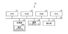
まず、POS端末10について説明する。図2は、POS端末10のハードウェア構成の一例を示すブロック図である。図2に示すように、POS端末10は、CPU(Central Processing Unit)11と、ROM(Read Only Memory)12と、RAM(Random Access Memory)13と、RTC(Real Time Clock)14とを備える。CPU11は、各種演算やPOS端末10の各部を統括的に制御する。ROM12は、各種プログラムやデータを記憶する。RAM13は、各種プログラムを一時的に記憶するとともに、各種データを書き換え自在に記憶する。RTC14は、現在の日時を計時する。 First, the
また、CPU11は、バス18を介して、記憶部15、通信インタフェース16、及び表示部17と接続している。 The
記憶部15は、例えば、HDD(Hard Disk Drive)やSSD(Solid State Drive)等の補助記憶装置である。記憶部15は、CPU11が実行する各種プログラムを記憶する。具体的には、記憶部15は、例えば、報知プログラムPR1を記憶する。報知プログラムPR1は、周辺機器20の充電状態を報知するプログラムである。 The
通信インタフェース16は、周辺機器20と無線で接続可能なインタフェースである。具体的には、通信インタフェース16は、例えば、Bluetooth(登録商標)等の規格により通信する。なお、通信インタフェース16は、Bluetooth(登録商標)以外の規格を採用してもよい。例えば、通信インタフェース16は、Wireless Fidelity(登録商標)等の規格により通信してもよい。 The
表示部17は、例えば、液晶ディスプレイ等である。そして、表示部17は、売上登録された商品の品名、価格、決済が宣言された一取引の合計金額、釣銭額等の各種情報を表示する。また、表示部17は、タッチパネルを備えてもよい。 The
次に、周辺機器20について説明する。図3は、周辺機器20のハードウェア構成の一例を示すブロック図である。図3に示すように、周辺機器20は、CPU21と、ROM22と、RAM23と、RTC24とを備える。CPU21は、各種演算や周辺機器20の各部を統括的に制御する。ROM22は、周辺機器20を制御するファームウェアなどの各種プログラムやデータを記憶する。具体的には、ROM22は、例えば、充電監視プログラムPR2を記憶する。充電監視プログラムPR2は、周辺機器20の充電状態を監視するプログラムである。RAM23は、各種プログラムを一時的に記憶するとともに、各種データを書き換え自在に記憶する。RTC24は、現在の日時を計時する。 Next, the
CPU21は、バス28を介して、通信インタフェース25と、二次電池26と、非接触受電部27と接続している。 The
通信インタフェース25は、POS端末10と無線で接続可能なインタフェースである。具体的には、通信インタフェース25は、例えば、Bluetooth(登録商標)等の規格により通信する。なお、通信インタフェース25は、Bluetooth(登録商標)以外の規格を採用してもよい。例えば、通信インタフェース25は、Wireless Fidelity(登録商標)等の規格により通信してもよい。但し、通信インタフェース25は、POS端末10の通信インタフェース16と同一の規格を採用するものとする。 The
二次電池26は、充電により電気を蓄えることが可能な電池である。二次電池26は、周辺機器20の各部が使用する電力を供給する。二次電池26は、例えば、リチウムイオン電池などである。なお、二次電池26は、リチウムイオン電池以外の種類であってもよい。 The
受電部である非接触受電部27は、非接触充電器30から非接触により送電された電力を受電する。また、非接触受電部27は、受電した電力を整流する。そして、非接触受電部27は、整流した電力を二次電池26に充電する。非接触給電の方式は、公知技術を用いるものとする。非接触給電の方式は、電磁誘導方式であってもよいし、磁界共鳴方式であってもよいし、これ以外の方式であってもよい。 The non-contact
ここで、電磁誘導方式とは、電磁誘導を利用して非接触により電力を供給する方式である。電磁誘導方式では、電力を供給する送電側と、電力を供給される受電側とにそれぞれコイルを備える。そして、電磁誘導方式では、送電側のコイルと受電側のコイルとを、隣接した位置に向い合うように配置する。送電側のコイルは、電流が供給されるとコイルの内側に磁束を発生させる。受電側のコイルは、送電側のコイルと隣接した位置に向い合うように配置されているため、受電側のコイルの内側にも磁束が及び、誘導電流を生じさせる。従って、送電側のコイルは、受電側のコイルに非接触で電力が供給することができる。なお、電磁誘導方式は、送電側のコイルの磁束を用いて、受電側のコイルに誘導電流を生じさせているため、送電側と受電側のコイルの位置のずれにより給電効率が低下する場合がある。 Here, the electromagnetic induction method is a method of supplying electric power in a non-contact manner using electromagnetic induction. In the electromagnetic induction method, a coil is provided on each of a power transmission side that supplies power and a power reception side that is supplied with power. In the electromagnetic induction method, the coil on the power transmission side and the coil on the power reception side are arranged so as to face the adjacent positions. The coil on the power transmission side generates a magnetic flux inside the coil when current is supplied. Since the coil on the power receiving side is disposed so as to face the position adjacent to the coil on the power transmitting side, the magnetic flux also reaches the inside of the coil on the power receiving side, and an induced current is generated. Therefore, the coil on the power transmission side can supply electric power to the coil on the power reception side in a non-contact manner. Note that the electromagnetic induction method uses the magnetic flux of the coil on the power transmission side to generate an induced current in the coil on the power reception side. is there.
また、非接触受電部27は、受電電力検出回路271を備える。受電電力検出回路271は、非接触充電器30から非接触により送電された電力の受電状態を検出する回路である。具体的には、受電電力検出回路271は、非接触充電器30から非接触により受電した単位時間当たりの電力量を検出する。 The non-contact
受電電力検出回路271は、検出した単位時間当たりの受電電力量から非接触給電の状態を判定する。受電電力検出回路271は、検出した受電電力量が第1の閾値より高い場合に、非接触給電の状態は良好であると判定する。受電電力検出回路271は、検出した受電電力量が第1の閾値より低く、第2の閾値より高い場合に、非接触給電の状態は不良であると判定する。受電電力検出回路271は、検出した受電電力量が第2の閾値より低い場合に、非接触給電の状態は不可であると判定する。 The received
次に、非接触充電器30について説明する。図4は、非接触充電器30のハードウェア構成の一例を示すブロック図である。図4に示すように、非接触充電器30は、配線33を介して、電源部31と、非接触送電部32とを接続している。 Next, the
電源部31は、電源ケーブル(不図示)を介して電力の供給を受ける。また、電源部31は、供給された電力を整流する。そして、電源部31は、整流した電力を非接触送電部32に供給する。 The
非接触送電部32は、電源部31から供給された電力を非接触により周辺機器20に送電する。なお、非接触給電の方式は、周辺機器20と同一の方式を用いるものとする。 The non-contact
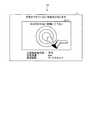
ここで、非接触充電器30は、周辺機器20が適切な位置に配置された場合に、非接触送電部32を介して、周辺機器20の非接触受電部27に電力を送電する。図5は、周辺機器20の適切な位置への配置の一例を示す説明図である。図6は、周辺機器20の不適切な位置への配置の一例を示す説明図である。図5及び図6に示す非接触充電器30は、上面に同心円301が描かれている。図5に示すように、周辺機器20は、同心円301の中心に置かれた場合に、非接触送電部32から送電された電力を受電することができる。ところが、図6に示すように、送電する電力は、同心円301の中心から離れた位置に周辺機器20が配置されると、距離に応じて減衰してしまう。そのため、周辺機器20の非接触受電部27は、非接触充電器30の非接触送電部32から送電された電力の全部又は一部を受電することができない。よって、周辺機器20は、非接触充電器30の適切な位置に配置されることが重要となる。ここで、適切な位置とは、非接触充電器30が発生させた磁束により非接触受電部27が誘導電流を生じさせる位置である。すなわち、適切な位置とは、周辺機器20の非接触受電部27が同心円301の中心と隣接する位置である。 Here, the
次に、POSシステム1の機能構成について説明する。図7は、POSシステム1の機能構成を示す図である。 Next, the functional configuration of the
まず、POS端末10の機能構成について説明する。図7に示すように、POS端末10は、機能部として、売上登録部111と、システム制御部112と、通信制御部113と、報知部114と、電源制御部115とを備える。具体的には、POS端末10のCPU11が、記憶部15に記憶された報知プログラムPR1を実行することにより、各機能部がRAM13上に生成される。 First, the functional configuration of the
売上登録部111は、一取引に係る販売対象の商品の売上登録処理を実行する。具体的には、売上登録部111は、コードスキャナである周辺機器20aや、キーボードである周辺機器20bを介して入力された商品コードや、価格や、販売個数に基づいて、売上マスタファイル等に記録して売上登録を行う。そして、売上登録部111は、プリンタである周辺機器20bに売上登録内容を印字させる。 The sales registration unit 111 executes a sales registration process for a product to be sold related to one transaction. Specifically, the sales registration unit 111 stores a sales master file or the like based on a product code, a price, or a sales quantity input via the
システム制御部112は、POSシステム1に係る非接触給電システムを制御する。すなわち、システム制御部112は、周辺機器20の非接触給電の状態を監視するために監視要求情報と、監視停止情報とを生成する。ここで、監視要求情報とは、非接触給電による単位時間当たりの受電電力量の監視を要求する情報である。監視停止情報とは、非接触給電による単位時間当たりの受電電力量の監視の停止を要求する情報である。POS端末10は、売上登録処理が終了すると、周辺機器20を使用しない状態となる。そこで、通信制御部113は、売上登録処理が終了した場合に、監視要求情報を周辺機器20に出力する。 The
例えば、コードスキャナである周辺機器20aは、売上登録処理中は商品に付された商品コードの読み取りに使用される。そのため、コードスキャナである周辺機器20aは、売上登録処理中は非接触充電器30から送電された電力を受電することができない。従って、POS端末10は、売上登録処理中は非接触給電の監視を停止しないと誤報を発してしまう。そこで、通信制御部113は、誤報を防止するために、売上登録処理が終了した場合に、監視要求情報を周辺機器20に出力する。そして、通信制御部113は、売上登録処理が開始された場合に、監視停止情報を周辺機器20に出力する。 For example, the
通信制御手段である通信制御部113は、通信インタフェース16を介して、自装置と無線接続された周辺機器20との通信を制御する。通信制御部113は、通信インタフェース16がBluetooth(登録商標)等の規格により通信する場合には、ペアリングされた周辺機器20との通信を制御する。ここで、ペアリングとは、近くにいる無関係な機器と通信しないように、通信する周辺機器20とPOS端末10とを対応付ける処理である。 The
そして、通信制御部113は、監視要求情報や、監視停止情報を、POSシステム1が有する1または複数の周辺機器20に送信する。すなわち、通信制御部113は、周辺機器20aと、周辺機器20bと、周辺機器20cとに監視要求情報や、監視停止情報を出力する。 Then, the
また、通信制御部113は、充電状態情報を周辺機器20から受信する。すなわち、入力手段である通信制御部113は、周辺機器20から出力された充電状態情報の入力を受け付ける。ここで、充電状態情報とは、充電状態情報を出力した周辺機器20の非接触給電の状態を示す情報である。充電状態情報は、非接触給電状態と、充電残量と、周辺機器コードとを有する。非接触給電状態は、周辺機器20と非接触充電器30との非接触給電における単位時間当たりの受電電力量を示す情報である。充電残量は、周辺機器20の二次電池26に充電された電力の残量を示す情報である。周辺機器コードは、充電状態情報を出力した周辺機器20を識別可能な識別情報である。 Further, the
報知部114は、周辺機器20の非接触給電の状態を報知する。すなわち、報知手段である報知部114は、通信制御部113が充電状態情報の入力を受け付けた場合に、周辺機器20の非接触給電状態を報知する。具体的には、報知部114は、充電状態情報の入力を受け付けた場合に、報知画面を生成する。そして、報知部114は、報知画面を表示部17に表示する。 The
ここで、図8は、報知画面G1の一例を示す説明図である。報知画面G1は、非接触給電により周辺機器20が受電した電力が閾値より低いことを報知する画面である。図8に示す報知画面G1は、非接触給電状態が不可、充電量が60%、周辺機器コードがコードスキャナを示す充電状態情報の入力を受け付けた場合の例である。図8に示す報知画面G1は、「充電ができていない可能性があります」とのメッセージを表示して報知する。また、報知画面G1は、修正依頼画面G11を有する。修正依頼画面G11は、周辺機器20の配置場所の修正を依頼する画面である。また、図8に示す修正依頼画面G11は、「まる印の中央に移動して下さい」とのメッセージと、画像とを表示している。 Here, FIG. 8 is an explanatory diagram illustrating an example of the notification screen G1. The notification screen G1 is a screen for notifying that the power received by the
また、報知部114は、非接触給電状態が示す単位時間当たりの受電電力量に応じて報知態様を変えてもよい。例えば、報知部114は、非接触給電状態が不可と不良とに応じて、報知画面G1に表示するメッセージや画像を変える。または、報知部114は、非接触給電状態が不可の場合には、表示部17の全画面に報知画面G1を表示させる。そして、報知部114は、非接触給電状態が不良の場合には、表示部17の一部に非接触給電状態が不良であることを示すマークや、アイコンや、文字等を表示させるなどの態様でもよい。 Moreover, the alerting | reporting
また、報知部114は、非接触給電状態が示す単位時間当たりの受電電力量に関わらず、非接触給電状態を報知してもよい。具体的には、報知部114は、充電状態情報が入力された場合に、表示部17の全部または一部に報知画面G1を表示させる。または、報知部114は、充電状態情報が有する内容を示したマークや、アイコンや、文字等を表示部17の一部に持続的に表示させてもよい。これにより、オペレータは、周辺機器20を適切な位置に配置していることを確認することができる。 Moreover, the alerting | reporting
電源制御部115は、POS端末10のシャットダウン処理を制御する。電源制御部115は、シャットダウン処理を要求する操作が入力された場合に、POS端末10をシャットダウン処理により停止する。 The
次に、周辺機器20の機能構成について説明する。図7に示すように、周辺機器20は、機能部として、非接触受電制御部211と、充電監視部212と、通信制御部213と、電源制御部214とを備える。具体的には、周辺機器20のCPU21が、ROM22に記憶された充電監視プログラムPR2を実行することにより、各機能部がRAM23上に生成される。 Next, the functional configuration of the
非接触受電制御部211は、周辺機器20の非接触給電を制御する。非接触受電制御部211は、非接触受電部27を介して、周辺機器20から送電された電力を受電する。そして、非接触受電制御部211は、受電した電力を二次電池26に充電する。 The non-contact power
監視手段である充電監視部212は、非接触受電部27を介して非接触充電器30から受電した電力を監視する。そして、充電監視部212は、充電状態情報を生成する。 The
充電監視部212は、POS端末10から出力された監視要求情報の入力を受け付けた場合に、非接触で受電した電力量を監視する。そして、充電監視部212は、POS端末10から出力された監視停止情報の入力を受け付けた場合に、非接触で受電した電力の監視を停止する。これにより、充電監視部212は、自装置が使用されており、非接触給電することができない状態であるにも関わらず報知してしまう誤報を防止する。 When the
また、オペレータは、売上登録処理の終了後であったとしても、周辺機器20を一時的に非接触充電器30から退かした場合や、売上登録処理の完了直後など意図的に周辺機器20を非接触充電器30に配置しない場合がある。このような場合であっても、非接触給電が不良又は不可であるとして直ちに報知されると、オペレータは、煩雑な報知に対応しなければならなくなる。そこで、充電監視部212は、設定時間が経過するまでに非接触給電の不良又は不可が解消されない場合に、充電状態情報を生成する。 In addition, even after the sales registration processing is completed, the operator intentionally removes the
具体的には、充電監視部212は、監視要求情報の入力を受け付けると、タイマーに初期値を設定する。そして、充電監視部212は、タイマーの計時を開始する。充電監視部212は、非接触給電の状態が良好の場合に、再度タイマーに初期値を設定する。一方、充電監視部212は、非接触給電の状態が不良又は不可の場合に、タイマーの計時を維持する。そして、充電監視部212は、タイマー値が設定時間となった場合に、充電状態情報を生成する。 Specifically, when the
その際、充電監視部212は、二次電池26に充電されている電力の充電残量を計測する。そして、充電監視部212は、非接触給電状態と、充電残量と、自装置を示す周辺機器コードとを有する充電状態情報を生成する。 At that time, the
通信制御部213は、通信インタフェース25を介した、POS端末10との通信を制御する。具体的には、通信制御部113は、充電監視情報をPOS端末10に送信する。すなわち、出力手段である通信制御部113は、受電した電力量が第1の閾値より低い場合に、充電監視部212が生成した充電状態情報を出力する。また、通信制御部113は、監視要求情報や、監視停止情報を、POS端末10から受信する。すなわち、入力手段である通信制御部113は、非接触給電の監視を要求する監視要求情報の入力を受け付ける。 The
電源制御部214は、周辺機器20のシャットダウン処理を制御する。電源制御部214は、シャットダウン処理を要求する操作が入力された場合に、周辺機器20をシャットダウン処理により停止する。 The
次に、上述した実施形態にかかるPOS端末10のCPU11が報知プログラムPR1に従って実行する報知処理について説明する。報知処理とは、周辺機器20の充電状態を報知する処理である。 Next, notification processing executed by the
図9は、POS端末10のCPU11が報知プログラムPR1に従って実行する報知処理の流れを示すフローチャートである。 FIG. 9 is a flowchart showing a flow of notification processing executed by the
まず、POS端末10の売上登録部111は、一取引に係る売上登録処理を終了したか否かを判定する(ステップS11)。売上登録処理を終了していない場合に(ステップS11;No)、POS端末10の売上登録部111は、報知処理を待機する。 First, the sales registration unit 111 of the
一方、売上登録処理を終了した場合に(ステップS11;Yes)、POS端末10のシステム制御部112は、監視要求情報を生成する(ステップS12)。次いで、POS端末10の通信制御部113は、監視要求情報を周辺機器20に出力する(ステップS13)。 On the other hand, when the sales registration process is completed (step S11; Yes), the
次いで、POS端末10の通信制御部113は、充電状態情報の入力を受け付けるか否かを判定する(ステップS14)。充電状態情報の入力を受け付けた場合に(ステップS14;Yes)、POS端末10の報知部114は、報知画面G1を表示させる(ステップS15)。そして、POS端末10のCPU11は、ステップS14に移行する。 Next, the
一方、充電状態情報の入力を受け付けていない場合に(ステップS14;No)、POS端末10の売上登録部111は、売上登録処理が開始されるか否かを判定する(ステップS16)。 On the other hand, when the input of the charging state information is not accepted (step S14; No), the sales registration unit 111 of the
売上登録処置が開始された場合に(ステップS16;Yes)、POS端末10のシステム制御部112は、監視停止情報を生成する(ステップS17)。POS端末10の通信制御部113は、監視停止情報を周辺機器20に出力する(ステップS18)。そして、POS端末10のCPU11は、ステップS11に移行する。 When the sales registration procedure is started (step S16; Yes), the
一方、売上登録処置が開始されない場合に(ステップS16;No)、POS端末10の電源制御部115は、POS端末10がシャットダウンされるか否かを判定する(ステップS19)。POS端末10がシャットダウンされない場合に(ステップS19;No)、POS端末10のCPU11は、ステップS14に移行する。 On the other hand, when the sales registration procedure is not started (step S16; No), the
一方、POS端末10がシャットダウンされた場合に(ステップS19;Yes)、POS端末10のCPU11は、報知処理を終了する。 On the other hand, when the
次に、上述した実施形態にかかる周辺機器20のCPU21が充電監視プログラムPR2に従って実行する充電監視処理について説明する。充電監視処理とは、周辺機器20の充電状態を監視する処理である。 Next, a charge monitoring process executed by the
図10は、周辺機器20のCPU21が充電監視プログラムPR2に従って実行する充電監視処理の流れを示すフローチャートである。 FIG. 10 is a flowchart showing a flow of the charge monitoring process executed by the
まず、周辺機器20の通信制御部213は、監視要求情報の入力を受け付けるか否かを判定する(ステップS21)。監視要求情報の入力を受け付けていない場合に(ステップS21;No)、周辺機器20のCPU21は、充電監視処理を待機する。 First, the
一方、監視要求情報の入力を受け付けた場合に(ステップS21;Yes)、周辺機器20の充電監視部212は、タイマーに初期値を設定する(ステップS22)。次いで、周辺機器20の充電監視部212は、非接触給電状態が良好であるか否かを判定する(ステップS23)。 On the other hand, when the input of the monitoring request information is received (step S21; Yes), the
非接触給電状態が良好でない場合に(ステップS23;No)、周辺機器20の充電監視部212は、設定時間が経過したか否かを判定する(ステップS24)。設定時間が経過していない場合に(ステップS24;No)、周辺機器20のCPU21は、ステップS23に移行する。 When the non-contact power supply state is not good (step S23; No), the
一方、設定時間が経過した場合に(ステップS24;Yes)、周辺機器20の充電監視部212は、二次電池26に充電されている電力の充電残量を計測する(ステップS25)。次いで、周辺機器20の充電監視部212は、非接触給電の状態と、充電残量と、自装置を示す周辺機器コードとを有する充電状態情報を生成する(ステップS26)。 On the other hand, when the set time has elapsed (step S24; Yes), the
次いで、周辺機器20の通信制御部213は、充電状態情報をPOS端末10に出力する(ステップS27)。そして、周辺機器20のCPU21は、ステップS28に移行する。 Next, the
非接触給電状態が良好である場合に(ステップS23;Yes)、周辺機器20の通信制御部213は、監視停止情報の入力を受け付けるか否かを判定する(ステップS28)。監視停止情報の入力を受け付けない場合に(ステップS28;No)、周辺機器20のCPU21は、ステップS22に移行する。 When the non-contact power supply state is good (step S23; Yes), the
一方、監視停止情報の入力を受け付けた場合に(ステップS28;Yes)、周辺機器20の電源制御部214は、周辺機器20がシャットダウンされるか否かを判定する(ステップS29)。周辺機器20がシャットダウンされない場合に(ステップS29;No)、周辺機器20のCPU21は、ステップS21に移行する。 On the other hand, when input of monitoring stop information is received (step S28; Yes), the power
一方、周辺機器20がシャットダウンされた場合に(ステップS29;Yes)、周辺機器20のCPU21は、充電監視処理を終了する。 On the other hand, when the
以上のように、本実施形態のPOSシステム1によれば、POS端末10は、自装置と対応付けられた周辺機器20から周辺機器20の非接触給電の状態を示す充電状態情報を受信する。そして、POS端末10は、充電状態情報を受信した場合に、周辺機器20の非接触給電情報を報知する。よって、POS端末10は、周辺機器20の非接触給電に係る状態を報知することができる。 As described above, according to the
本発明のいくつかの実施形態を説明したが、これらの実施形態は、例として提示したものであり、発明の範囲を限定することは意図していない。これら新規な実施形態は、その他の様々な形態で実施されることが可能であり、発明の要旨を逸脱しない範囲で、種々の省略、置き換え、変更を行うことができる。これら実施形態やその変形は、発明の範囲や要旨に含まれるとともに、特許請求の範囲に記載された発明とその均等の範囲に含まれる。 Although several embodiments of the present invention have been described, these embodiments are presented by way of example and are not intended to limit the scope of the invention. These novel embodiments can be implemented in various other forms, and various omissions, replacements, and changes can be made without departing from the scope of the invention. These embodiments and modifications thereof are included in the scope and gist of the invention, and are included in the invention described in the claims and the equivalents thereof.
また、上記実施形態では、POS端末10の報知部114は、報知画面G1を表示部17に表示することにより報知すると説明している。しかしながら、報知部114は、報知画面G1の表示以外の方法により報知してもよい。例えば、報知部114は、非接触給電状態が不良又は不可であること通知する音声等により報知してもよい。 Moreover, in the said embodiment, the alerting | reporting
また、上記実施形態では、充電状態情報に係る非接触給電状態は、受電電力検出回路271が判定すると説明している。しかしながら、充電状態情報に係る非接触給電状態は、周辺機器20のCPU21が判定してもよい。この場合には、受電電力検出回路271は、単位時間当たりの受電電力量をCPU21に通知する。そして、CPU21は、通知された受電電力量に基づいて、非接触給電状態について判定すればよい。そして、CPU21が判定する場合にはソフトウェアを用いるため、非接触給電状態に係る閾値は、任意の値を設定することが可能となる。 Moreover, in the said embodiment, it has demonstrated that the received
上記実施形態や変形例の各装置で実行されるプログラムは、各装置が備える記憶媒体(ROM又は記憶部)に予め組み込んで提供するものとするが、これに限らないものとする。例えば、インストール可能な形式又は実行可能な形式のファイルでCD−ROM、フレキシブルディスク(FD)、CD−R、DVD(Digital Versatile Disk)等のコンピュータで読み取り可能な記録媒体に記録して提供するように構成してもよい。さらに、記憶媒体は、コンピュータ或いは組み込みシステムと独立した媒体に限らず、LANやインターネット等により伝達されたプログラムをダウンロードして記憶又は一時記憶した記憶媒体も含まれる。 The program executed by each device of the above-described embodiment or modification is provided by being incorporated in advance in a storage medium (ROM or storage unit) included in each device, but is not limited thereto. For example, an installable or executable file is recorded on a computer-readable recording medium such as a CD-ROM, a flexible disk (FD), a CD-R, or a DVD (Digital Versatile Disk). You may comprise. Furthermore, the storage medium is not limited to a medium independent of a computer or an embedded system, but also includes a storage medium in which a program transmitted via a LAN, the Internet, or the like is downloaded and stored or temporarily stored.
また、上記実施形態や変形例の各装置で実行されるプログラムをインターネット等のネットワークに接続されたコンピュータ上に格納し、ネットワーク経由でダウンロードさせることにより提供するように構成してもよいし、インターネット等のネットワーク経由で提供又は配布するように構成してもよい。 Further, the program executed by each device of the above-described embodiment or modification may be stored on a computer connected to a network such as the Internet and provided by being downloaded via the network, or the Internet It may be configured to be provided or distributed via a network.
1 POSシステム
10 POS端末
111 売上登録部
112 システム制御部
113 通信制御部
114 報知部
115 電源制御部
20 周辺機器
211 非接触受電制御部
212 充電監視部
213 通信制御部
214 電源制御部
30 非接触充電器DESCRIPTION OF
Claims (6)
Translated fromJapanese前記周辺機器から出力された当該周辺機器の機械的な接続のない非接触による非接触給電の状態を示す充電状態情報の入力を受け付ける入力手段と、
前記入力手段が前記充電状態情報の入力を受け付けた場合に、前記周辺機器の前記非接触給電の状態を報知する報知手段と、
を備える情報処理装置。Communication control means for controlling communication with a peripheral device associated with the own device;
Input means for receiving input of charge state information indicating a state of non-contact power feeding by non-contact without mechanical connection of the peripheral device output from the peripheral device;
Informing means for notifying the state of the non-contact power feeding of the peripheral device when the input means accepts the input of the charging state information;
An information processing apparatus comprising:
前記報知手段は、前記非接触給電により前記周辺機器が受電した電力が閾値より低いことを示す画面を前記表示部に表示することで報知する、
請求項1に記載の情報処理装置。A display unit;
The notification means notifies the display unit by displaying a screen indicating that the power received by the peripheral device by the non-contact power supply is lower than a threshold value,
The information processing apparatus according to claim 1.
請求項1または2に記載の情報処理装置。The communication control means outputs monitoring request information for requesting monitoring of the non-contact power feeding of the peripheral device when the device is in a state of not using the peripheral device.
The information processing apparatus according to claim 1 or 2.
前記報知手段は、前記受電電力量に応じて報知態様を変える、
請求項1乃至3の何れか1に記載の情報処理装置。The input means accepts an input of the charge state information having information indicating the amount of received power per unit time,
The notification means changes a notification mode according to the received power amount.
The information processing apparatus according to any one of claims 1 to 3.
前記報知手段は、前記識別情報を報知する、
請求項1乃至4の何れか1に記載の情報処理装置。The input means accepts input of the charge state information having identification information that can identify the peripheral device that outputs the charge state information;
The notification means notifies the identification information;
The information processing apparatus according to any one of claims 1 to 4.
前記受電部を介して、受電した電力を監視する監視手段と、
前記監視手段が監視した電力量を示す情報を含む前記非接触給電の状態を示す充電状態情報を情報処理装置に出力する出力手段と、
を備える周辺機器。A power receiving unit that receives power transmitted by non-contact power feeding by non-contact without mechanical connection;
Monitoring means for monitoring the received power via the power receiving unit;
Output means for outputting, to an information processing device, charge state information indicating the state of the non-contact power supply including information indicating the amount of power monitored by the monitoring means;
Peripheral equipment equipped with.
Priority Applications (4)
| Application Number | Priority Date | Filing Date | Title |
|---|---|---|---|
| JP2015001061AJP2016127740A (en) | 2015-01-06 | 2015-01-06 | Information processing apparatus and peripheral equipment |
| US14/930,700US10061372B2 (en) | 2015-01-06 | 2015-11-03 | Information processing apparatus and peripheral device used by the same |
| EP15202751.2AEP3043485A1 (en) | 2015-01-06 | 2015-12-24 | Information processing apparatus and peripheral device used by the same |
| CN201511001076.7ACN105761387B (en) | 2015-01-06 | 2015-12-28 | Information processing unit and peripheral equipment |
Applications Claiming Priority (1)
| Application Number | Priority Date | Filing Date | Title |
|---|---|---|---|
| JP2015001061AJP2016127740A (en) | 2015-01-06 | 2015-01-06 | Information processing apparatus and peripheral equipment |
Related Child Applications (1)
| Application Number | Title | Priority Date | Filing Date |
|---|---|---|---|
| JP2017218287ADivisionJP2018029476A (en) | 2017-11-13 | 2017-11-13 | Information processing device |
Publications (1)
| Publication Number | Publication Date |
|---|---|
| JP2016127740Atrue JP2016127740A (en) | 2016-07-11 |
Family
ID=54979609
Family Applications (1)
| Application Number | Title | Priority Date | Filing Date |
|---|---|---|---|
| JP2015001061APendingJP2016127740A (en) | 2015-01-06 | 2015-01-06 | Information processing apparatus and peripheral equipment |
Country Status (4)
| Country | Link |
|---|---|
| US (1) | US10061372B2 (en) |
| EP (1) | EP3043485A1 (en) |
| JP (1) | JP2016127740A (en) |
| CN (1) | CN105761387B (en) |
Cited By (3)
| Publication number | Priority date | Publication date | Assignee | Title |
|---|---|---|---|---|
| JP2018032239A (en)* | 2016-08-25 | 2018-03-01 | 東芝テック株式会社 | Information processing device |
| JP2018045314A (en)* | 2016-09-12 | 2018-03-22 | 東芝テック株式会社 | Wireless communication system, information output device, and product sales information processing device |
| JP2018085035A (en)* | 2016-11-25 | 2018-05-31 | 株式会社デンソー | Wireless power supply system and power transmission/reception monitoring program |
Families Citing this family (2)
| Publication number | Priority date | Publication date | Assignee | Title |
|---|---|---|---|---|
| FI128565B (en) | 2018-05-07 | 2020-08-14 | Oura Health Oy | A system and a method for indicating information representing battery status of an electronic device |
| JP2021092861A (en)* | 2019-12-06 | 2021-06-17 | 東芝テック株式会社 | Electronic device |
Citations (11)
| Publication number | Priority date | Publication date | Assignee | Title |
|---|---|---|---|---|
| JPH04243408A (en)* | 1991-01-18 | 1992-08-31 | Seiko Epson Corp | Wireless keyboard and information processing system utilizing wireless keyboard |
| JP2003153457A (en)* | 2001-11-09 | 2003-05-23 | Denso Corp | Noncontact charger |
| JP2003264934A (en)* | 2002-03-08 | 2003-09-19 | Denso Wave Inc | Non-contact charging system, charger, and charged equipment |
| JP2006141170A (en)* | 2004-11-15 | 2006-06-01 | Sharp Corp | Power supply system, power transmission device and power reception device used therefor |
| JP2006203989A (en)* | 2005-01-19 | 2006-08-03 | Fuji Photo Film Co Ltd | Battery residual quantity warning controller and battery residual quantity warning control method |
| JP2006238548A (en)* | 2005-02-23 | 2006-09-07 | Matsushita Electric Ind Co Ltd | Wireless power supply device |
| JP2013085363A (en)* | 2011-10-07 | 2013-05-09 | Hitachi Vehicle Energy Ltd | Battery state management device, battery state management method |
| JP2013207999A (en)* | 2012-03-29 | 2013-10-07 | Panasonic Corp | Vehicle guidance device, vehicle guidance information providing device and vehicle guidance method |
| JP2013216042A (en)* | 2012-04-11 | 2013-10-24 | Sato Holdings Corp | Printer |
| JP2014017989A (en)* | 2012-07-10 | 2014-01-30 | Nec Casio Mobile Communications Ltd | Mobile terminal, contactless charging system, and management method of contactless charging |
| JP2014135862A (en)* | 2013-01-11 | 2014-07-24 | Canon Inc | Power feeding device, image forming apparatus, and power feeding method and program |
Family Cites Families (28)
| Publication number | Priority date | Publication date | Assignee | Title |
|---|---|---|---|---|
| US5963012A (en)* | 1998-07-13 | 1999-10-05 | Motorola, Inc. | Wireless battery charging system having adaptive parameter sensing |
| KR100554889B1 (en)* | 2005-03-21 | 2006-03-03 | 주식회사 한림포스텍 | Contactless charging system |
| US7715884B2 (en)* | 2005-10-14 | 2010-05-11 | Research In Motion Limited | Mobile device with a smart battery having a battery information profile corresponding to a communication standard |
| KR100736053B1 (en)* | 2005-10-24 | 2007-07-06 | 삼성전자주식회사 | Apparatus and method for sharing power wirelessly by induction |
| US7989986B2 (en)* | 2006-03-23 | 2011-08-02 | Access Business Group International Llc | Inductive power supply with device identification |
| US7793121B2 (en)* | 2007-03-01 | 2010-09-07 | Eastman Kodak Company | Charging display system |
| WO2009041058A1 (en)* | 2007-09-27 | 2009-04-02 | Panasonic Corporation | Electronic device, recharger and recharging system |
| JP2009253762A (en)* | 2008-04-08 | 2009-10-29 | Sony Corp | Radio communication device, wireless communication system, radio communication method and program |
| US8111042B2 (en)* | 2008-08-05 | 2012-02-07 | Broadcom Corporation | Integrated wireless resonant power charging and communication channel |
| JP5258521B2 (en)* | 2008-11-14 | 2013-08-07 | トヨタ自動車株式会社 | Power supply system |
| JP2010206866A (en) | 2009-02-27 | 2010-09-16 | Panasonic Corp | Electronic equipment and charger |
| US8390249B2 (en)* | 2009-11-30 | 2013-03-05 | Broadcom Corporation | Battery with integrated wireless power receiver and/or RFID |
| KR20110103295A (en)* | 2010-03-12 | 2011-09-20 | 삼성전자주식회사 | Wireless charging method using communication network |
| KR20120020661A (en)* | 2010-08-30 | 2012-03-08 | 엘지전자 주식회사 | Mobile terminal and method for wireless charging |
| US20120155349A1 (en)* | 2010-11-16 | 2012-06-21 | Zeljko Bajic | Rfid applications |
| US8665214B2 (en)* | 2010-12-29 | 2014-03-04 | Qualcomm Incorporated | Extending battery life of a portable electronic device |
| US8946939B2 (en)* | 2011-03-31 | 2015-02-03 | Qualcomm Incorporated | Systems and methods for detecting and protecting a wireless power communication device in a wireless power system |
| KR101810465B1 (en)* | 2011-06-10 | 2018-01-25 | 엘지전자 주식회사 | Apparatus for Handling of Orientation Changing of Terminal during Wireless Power Transfer and Method Thereof |
| US8898489B2 (en)* | 2011-07-25 | 2014-11-25 | Dell Products L.P. | Information handling system wireless power docking station module with shared power source and wireless peripheral support |
| DE202012000291U1 (en)* | 2012-01-13 | 2012-02-15 | Cei Conrad Electronic International (Hk) Ltd. | loader |
| US10270297B2 (en)* | 2012-08-06 | 2019-04-23 | Ge Hybrid Technologies, Llc | Apparatus and method for providing compatibility in wireless power transmission system |
| US20140059360A1 (en)* | 2012-08-23 | 2014-02-27 | Lifescan Scotland Limited | Power supplies management in an analyte device having primary and secondary batteries |
| KR101257676B1 (en) | 2012-12-07 | 2013-05-02 | 주식회사 에스엔파워콤 | Method and apparatus for display of aligment transmitter-receiver wireless charge |
| KR102049075B1 (en)* | 2013-01-08 | 2019-11-26 | 삼성전자주식회사 | Method and apparatus for displaying information on wireless charging pad in electronic device |
| JP2014153894A (en) | 2013-02-07 | 2014-08-25 | Toshiba Tec Corp | Information processor and program |
| US9559544B2 (en)* | 2013-03-15 | 2017-01-31 | Jay Marketing Associates, Inc. | Wireless interrogation and wireless charging of electronic devices |
| US9973038B2 (en) | 2013-06-10 | 2018-05-15 | Celico Partnership | Self optimizing antenna for NFC and wireless charging |
| US9792622B2 (en)* | 2013-09-05 | 2017-10-17 | Avago Technologies General Ip (Singapore) Pte. Ltd. | Communicating device data prior to establishing wireless power connection |
- 2015
- 2015-01-06JPJP2015001061Apatent/JP2016127740A/enactivePending
- 2015-11-03USUS14/930,700patent/US10061372B2/enactiveActive
- 2015-12-24EPEP15202751.2Apatent/EP3043485A1/ennot_activeWithdrawn
- 2015-12-28CNCN201511001076.7Apatent/CN105761387B/ennot_activeExpired - Fee Related
Patent Citations (11)
| Publication number | Priority date | Publication date | Assignee | Title |
|---|---|---|---|---|
| JPH04243408A (en)* | 1991-01-18 | 1992-08-31 | Seiko Epson Corp | Wireless keyboard and information processing system utilizing wireless keyboard |
| JP2003153457A (en)* | 2001-11-09 | 2003-05-23 | Denso Corp | Noncontact charger |
| JP2003264934A (en)* | 2002-03-08 | 2003-09-19 | Denso Wave Inc | Non-contact charging system, charger, and charged equipment |
| JP2006141170A (en)* | 2004-11-15 | 2006-06-01 | Sharp Corp | Power supply system, power transmission device and power reception device used therefor |
| JP2006203989A (en)* | 2005-01-19 | 2006-08-03 | Fuji Photo Film Co Ltd | Battery residual quantity warning controller and battery residual quantity warning control method |
| JP2006238548A (en)* | 2005-02-23 | 2006-09-07 | Matsushita Electric Ind Co Ltd | Wireless power supply device |
| JP2013085363A (en)* | 2011-10-07 | 2013-05-09 | Hitachi Vehicle Energy Ltd | Battery state management device, battery state management method |
| JP2013207999A (en)* | 2012-03-29 | 2013-10-07 | Panasonic Corp | Vehicle guidance device, vehicle guidance information providing device and vehicle guidance method |
| JP2013216042A (en)* | 2012-04-11 | 2013-10-24 | Sato Holdings Corp | Printer |
| JP2014017989A (en)* | 2012-07-10 | 2014-01-30 | Nec Casio Mobile Communications Ltd | Mobile terminal, contactless charging system, and management method of contactless charging |
| JP2014135862A (en)* | 2013-01-11 | 2014-07-24 | Canon Inc | Power feeding device, image forming apparatus, and power feeding method and program |
Cited By (4)
| Publication number | Priority date | Publication date | Assignee | Title |
|---|---|---|---|---|
| JP2018032239A (en)* | 2016-08-25 | 2018-03-01 | 東芝テック株式会社 | Information processing device |
| JP2018045314A (en)* | 2016-09-12 | 2018-03-22 | 東芝テック株式会社 | Wireless communication system, information output device, and product sales information processing device |
| JP2018085035A (en)* | 2016-11-25 | 2018-05-31 | 株式会社デンソー | Wireless power supply system and power transmission/reception monitoring program |
| WO2018096754A1 (en)* | 2016-11-25 | 2018-05-31 | 株式会社デンソー | Wireless power supply system and power transmission and receiving monitor program |
Also Published As
| Publication number | Publication date |
|---|---|
| US10061372B2 (en) | 2018-08-28 |
| EP3043485A1 (en) | 2016-07-13 |
| CN105761387B (en) | 2019-07-30 |
| CN105761387A (en) | 2016-07-13 |
| US20160195915A1 (en) | 2016-07-07 |
Similar Documents
| Publication | Publication Date | Title |
|---|---|---|
| US11539400B2 (en) | Power supply apparatus and electronic apparatus configured to carry out wireless power supply | |
| JP2016127740A (en) | Information processing apparatus and peripheral equipment | |
| US11329695B2 (en) | Power supply apparatus, power supply method, and recording medium | |
| JP6254957B2 (en) | Information processing device, peripheral device and non-contact power supply system | |
| US9482723B2 (en) | Wireless power supply system, power transmission device, and power receiving device | |
| JP2009219177A (en) | Feeder system | |
| CN105844816B (en) | Information processing unit, information processing system and information processing method | |
| US20140084854A1 (en) | Portable terminal device, charging method, and program | |
| US20140292094A1 (en) | Power supply apparatus, power supply method, and recording medium | |
| CN105229560A (en) | Method and apparatus for providing power to a device | |
| US20250007332A1 (en) | Wireless Power System With Charging Alerts | |
| US11201506B2 (en) | Power transfer system, power receiving apparatus, control method, and storage medium | |
| JP2012205485A (en) | Electronic equipment, charging system and charging abnormality notification method | |
| JP2018029476A (en) | Information processing device | |
| JP6289386B2 (en) | Printing device and program | |
| JP7105585B2 (en) | Payment terminal and program | |
| JP7244576B2 (en) | Information processing device and program | |
| JP2017017872A (en) | Non-contact power supplier | |
| KR20190028119A (en) | Wireless charging application system with enhanced advertising function | |
| JP2014168324A (en) | Display system |
Legal Events
| Date | Code | Title | Description |
|---|---|---|---|
| A621 | Written request for application examination | Free format text:JAPANESE INTERMEDIATE CODE: A621 Effective date:20160822 | |
| A977 | Report on retrieval | Free format text:JAPANESE INTERMEDIATE CODE: A971007 Effective date:20170526 | |
| A131 | Notification of reasons for refusal | Free format text:JAPANESE INTERMEDIATE CODE: A131 Effective date:20170530 | |
| A521 | Request for written amendment filed | Free format text:JAPANESE INTERMEDIATE CODE: A523 Effective date:20170721 | |
| A02 | Decision of refusal | Free format text:JAPANESE INTERMEDIATE CODE: A02 Effective date:20170815 |