JP2016123854A - Loading unit locking collar - Google Patents
Loading unit locking collarDownload PDFInfo
- Publication number
- JP2016123854A JP2016123854AJP2015240912AJP2015240912AJP2016123854AJP 2016123854 AJP2016123854 AJP 2016123854AJP 2015240912 AJP2015240912 AJP 2015240912AJP 2015240912 AJP2015240912 AJP 2015240912AJP 2016123854 AJP2016123854 AJP 2016123854A
- Authority
- JP
- Japan
- Prior art keywords
- locking collar
- lock
- loading unit
- assembly
- pair
- Prior art date
- Legal status (The legal status is an assumption and is not a legal conclusion. Google has not performed a legal analysis and makes no representation as to the accuracy of the status listed.)
- Granted
Links
Images


Classifications
- A—HUMAN NECESSITIES
- A61—MEDICAL OR VETERINARY SCIENCE; HYGIENE
- A61B—DIAGNOSIS; SURGERY; IDENTIFICATION
- A61B17/00—Surgical instruments, devices or methods
- A61B17/11—Surgical instruments, devices or methods for performing anastomosis; Buttons for anastomosis
- A61B17/115—Staplers for performing anastomosis, e.g. in a single operation
- A61B17/1155—Circular staplers comprising a plurality of staples
- A—HUMAN NECESSITIES
- A61—MEDICAL OR VETERINARY SCIENCE; HYGIENE
- A61B—DIAGNOSIS; SURGERY; IDENTIFICATION
- A61B17/00—Surgical instruments, devices or methods
- A61B2017/0046—Surgical instruments, devices or methods with a releasable handle; with handle and operating part separable
- A61B2017/00473—Distal part, e.g. tip or head
- A—HUMAN NECESSITIES
- A61—MEDICAL OR VETERINARY SCIENCE; HYGIENE
- A61B—DIAGNOSIS; SURGERY; IDENTIFICATION
- A61B17/00—Surgical instruments, devices or methods
- A61B17/068—Surgical staplers, e.g. containing multiple staples or clamps
- A61B17/072—Surgical staplers, e.g. containing multiple staples or clamps for applying a row of staples in a single action, e.g. the staples being applied simultaneously
- A61B2017/07214—Stapler heads
- A61B2017/07271—Stapler heads characterised by its cartridge
- A—HUMAN NECESSITIES
- A61—MEDICAL OR VETERINARY SCIENCE; HYGIENE
- A61B—DIAGNOSIS; SURGERY; IDENTIFICATION
- A61B17/00—Surgical instruments, devices or methods
- A61B17/28—Surgical forceps
- A61B17/29—Forceps for use in minimally invasive surgery
- A61B2017/2946—Locking means
Landscapes
- Health & Medical Sciences (AREA)
- Life Sciences & Earth Sciences (AREA)
- Surgery (AREA)
- Molecular Biology (AREA)
- Engineering & Computer Science (AREA)
- Biomedical Technology (AREA)
- Heart & Thoracic Surgery (AREA)
- Medical Informatics (AREA)
- Nuclear Medicine, Radiotherapy & Molecular Imaging (AREA)
- Animal Behavior & Ethology (AREA)
- General Health & Medical Sciences (AREA)
- Public Health (AREA)
- Veterinary Medicine (AREA)
- Surgical Instruments (AREA)
- Quick-Acting Or Multi-Walled Pipe Joints (AREA)
- Snaps, Bayonet Connections, Set Pins, And Snap Rings (AREA)
Abstract
Description
Translated fromJapanese 背景
1.技術分野
本開示は、概して、外科手術ステープル留め器具に関する。より詳しくは、本開示は、交換可能なローディングユニットを含む円形外科手術ステープル留め器具に関する。Background 1. TECHNICAL FIELD The present disclosure relates generally to surgical stapling instruments. More particularly, the present disclosure relates to a circular surgical stapling instrument that includes a replaceable loading unit.
2.関連技術の背景
外科手術手順中に組織部分を接合するように構成されている外科手術ステープル留めデバイスは、周知である。これらのデバイスは、デバイスの長手方向軸に対して平行に、または横断して配向されている線形エンドエフェクター、および円形エンドエフェクターを含む。代表的に、線形ステープル留めデバイスは、使い捨てローディングユニット、またはステープル留めデバイスが複数回使用されることを可能にする交換可能なカートリッジを含む。しかし、従来の円形ステープル留めデバイスは、デバイスに固定して取り付けられているカートリッジまたはシェルアセンブリを含み、その結果、デバイスは、単回使用の後、処分されなければならない。いくつかの円形ステープル留めデバイスは、交換可能であるカートリッジまたはシェルアセンブリを含む。2. Background of Related Art Surgical stapling devices configured to join tissue portions during a surgical procedure are well known. These devices include linear end effectors that are oriented parallel or transverse to the longitudinal axis of the device, and circular end effectors. Typically, linear stapling devices include disposable loading units or replaceable cartridges that allow the stapling device to be used multiple times. However, conventional circular stapling devices include a cartridge or shell assembly that is fixedly attached to the device, so that the device must be disposed of after a single use. Some circular stapling devices include a cartridge or shell assembly that is replaceable.
ステープル留めデバイスの再使用を容易にするために、カートリッジまたはシェルアセンブリを円形ステープル留めデバイスに解放可能に固定するための単純な費用のかからないデバイスの必要性が当該分野において存在する。 There is a need in the art for a simple and inexpensive device for releasably securing a cartridge or shell assembly to a circular stapling device to facilitate reuse of the stapling device.
概要
本開示の局面において、ローディングユニットおよび係止カラーのアセンブリは、シェルアセンブリと係止カラーとを含む。シェルアセンブリは、外科手術器具の遠位端部分を受け取るための近位端部分を有する。近位端部分は、外側表面と内側表面とを有する環状リングを含む。環状リングの外側表面は、近位端部分に環状溝を規定する。環状リングは、それを通してロック開口部を規定する。係止カラーは、環状溝内に解放可能に配置され、環状本体を含む。係止カラーの環状本体は、1対の解放表面とロックとを有する。ロックは、環状本体から半径方向内方に延びている。1対の解放表面は、係止カラーを係止された構成から係止されていない構成に移行するように構成されている。係止された構成において、ロックは、ロック開口部を通って延びて、環状リングの内側表面を貫通しており、係止されていない構成において、ロックは、環状リングの内側表面から半径方向外方に位置決めされている。Overview In aspects of the present disclosure, a loading unit and locking collar assembly includes a shell assembly and a locking collar. The shell assembly has a proximal end portion for receiving a distal end portion of a surgical instrument. The proximal end portion includes an annular ring having an outer surface and an inner surface. The outer surface of the annular ring defines an annular groove in the proximal end portion. The annular ring defines a lock opening therethrough. The locking collar is releasably disposed within the annular groove and includes an annular body. The annular body of the locking collar has a pair of release surfaces and a lock. The lock extends radially inward from the annular body. The pair of release surfaces is configured to transition the locking collar from the locked configuration to the unlocked configuration. In the locked configuration, the lock extends through the lock opening and penetrates the inner surface of the annular ring, and in the unlocked configuration, the lock is radially outward from the inner surface of the annular ring. It is positioned in the direction.
複数の局面において、解放表面の各々は、他方の解放表面に向かって押し付けられ、係止カラーを係止された構成から係止されていない構成に移行する。解放表面の各々は、半径方向内方に圧縮されて、係止カラーを係止されていない構成に向かって移行し得る。あるいは、解放表面の各々は、シェルアセンブリの長手方向軸に対して横断する面において、係止カラーの周囲で押し付けられて、係止カラーを係止されていない構成に向かって移行し得る。 In aspects, each of the release surfaces is pressed against the other release surface to transition the locking collar from the locked configuration to the unlocked configuration. Each of the release surfaces may be compressed radially inward to transition the locking collar toward an unlocked configuration. Alternatively, each of the release surfaces may be pressed around the locking collar in a plane transverse to the longitudinal axis of the shell assembly to transition the locking collar toward the unlocked configuration.
いくつかの局面において、係止カラーは、シェルアセンブリの長手方向軸に対して横断する面において、楕円形の断面を規定し、ここで、係止されていない構成における幅は、係止された構成における幅よりも小さい。幅は、1対の解放表面の間に規定され得る。あるいは、係止カラーは、シェルアセンブリの長手方向軸に対して横断する面において、楕円形の断面を規定し得、ここで、幅は、高さよりも小さい。 In some aspects, the locking collar defines an elliptical cross section in a plane transverse to the longitudinal axis of the shell assembly, where the width in the unlocked configuration is locked Less than the width in the configuration. The width can be defined between a pair of release surfaces. Alternatively, the locking collar may define an elliptical cross section in a plane transverse to the longitudinal axis of the shell assembly, where the width is less than the height.
特定の局面において、係止カラーは、係止された構成において、シェルアセンブリの長手方向軸に対して横断する面において、円形の断面を規定する。係止カラーは、シェルアセンブリの長手方向軸に対して横断する面において、楕円形の断面を規定し得、ここで、係止されていない構成において、幅は高さよりも小さい。高さは、1対の解放表面とロックとの間に規定され得る。 In certain aspects, the locking collar defines a circular cross section in a plane transverse to the longitudinal axis of the shell assembly in the locked configuration. The locking collar may define an elliptical cross section in a plane transverse to the longitudinal axis of the shell assembly, where the width is less than the height in the unlocked configuration. The height can be defined between a pair of release surfaces and a lock.
特定の局面において、係止カラーは、係止された構成に向かって付勢される。係止カラーの環状本体は、分かれて、第1の解放表面と第2の解放表面とを形成し得る。第1の表面は、環状本体の周囲で第1の方向に延び得、第2の解放表面は、環状本体の周囲で第1の方向と反対の第2の方向に延び得る。第1の解放表面および第2の解放表面は、各々が、端を含み得、端と環状本体との間に係合ウインドーを規定する。係止カラーは、係止カラーが係止されていない構成から係止された構成に移行する場合、しるしを提供するように構成され得る。しるしは、可聴であり得る。シェルアセンブリは、組織を通してステープルを発射するように構成され得る。 In certain aspects, the locking collar is biased toward the locked configuration. The annular body of the locking collar can be split to form a first release surface and a second release surface. The first surface may extend in a first direction around the annular body and the second release surface may extend in a second direction opposite the first direction around the annular body. The first release surface and the second release surface may each include an end and define an engagement window between the end and the annular body. The locking collar may be configured to provide an indication when the locking collar transitions from an unlocked configuration to a locked configuration. The indicia can be audible. The shell assembly may be configured to fire staples through tissue.
本開示の別の局面において、外科手術システムは、外科手術器具と、ローディングユニットと、係止カラーとを含む。外科手術器具は、遠位端を含む。ローディングユニットは、近位端部分を有するシェルアセンブリを含み、この近位端部分は、外科手術器具の遠位端上に位置決めされている。近位端部分は、外側表面と内側表面とを有する環状リングを含む。環状リングの外側表面は、近位端部分に環状溝を規定する。環状リングは、それを通してロック開口部を規定する。係止カラーは、ローディングユニットの環状溝内に解放可能に配置され、環状本体を含み、この環状本体は、1対の解放表面とロックとを有する。ロックは、環状本体から半径方向内方に延びている。1対の解放表面は、係止カラーを係止された構成から係止されていない構成に移行するように構成されている。係止された構成において、ロックは、ロック開口部を通って延びて、環状リングの内側表面を貫通しており、係止されていない構成において、ロックは、環状リングの内側表面から半径方向外方に位置決めされている。 In another aspect of the present disclosure, a surgical system includes a surgical instrument, a loading unit, and a locking collar. The surgical instrument includes a distal end. The loading unit includes a shell assembly having a proximal end portion that is positioned on the distal end of the surgical instrument. The proximal end portion includes an annular ring having an outer surface and an inner surface. The outer surface of the annular ring defines an annular groove in the proximal end portion. The annular ring defines a lock opening therethrough. The locking collar is releasably disposed within the annular groove of the loading unit and includes an annular body that has a pair of release surfaces and a lock. The lock extends radially inward from the annular body. The pair of release surfaces is configured to transition the locking collar from the locked configuration to the unlocked configuration. In the locked configuration, the lock extends through the lock opening and penetrates the inner surface of the annular ring, and in the unlocked configuration, the lock is radially outward from the inner surface of the annular ring. It is positioned in the direction.
複数の局面において、外科手術器具の遠位端は、ウインドーを規定する。ロックは、係止された構成において、ウインドーの中に延び得、係止されていない構成において、ウインドーの外に位置決めされ得る。係止カラーは、係止された構成において、ローディングユニットを外科手術器具の遠位端に固定し得、係止カラーは、係止されていない構成において、ローディングユニットが外科手術器具から取り外されることを可能にし得る。ロックは、近位ステップと、遠位ステップと、近位ステップと遠位ステップとの間の角度付き表面とを含み得る。角度付き表面は、ロックが外科手術器具の遠位端に規定されるウインドー内に位置決めされるまで、外科手術器具の遠位端部分上をスライドして、ロックを半径方向外方に移動するように構成され得る。 In aspects, the distal end of the surgical instrument defines a window. The lock can extend into the window in the locked configuration and can be positioned out of the window in the unlocked configuration. The locking collar may secure the loading unit to the distal end of the surgical instrument in the locked configuration, and the locking collar may be removed from the surgical instrument in the unlocked configuration. Can make it possible. The lock may include a proximal step, a distal step, and an angled surface between the proximal and distal steps. The angled surface slides on the distal end portion of the surgical instrument to move the lock radially outward until the lock is positioned within the window defined at the distal end of the surgical instrument. Can be configured.
さらに、本明細書中に記載される局面のうちの任意のものは、一貫した程度まで、本明細書中に記載される他の局面のうちの任意のものまたは全てとともに使用され得る。
本発明は、例えば以下の項目を提供する。
(項目1)
ローディングユニットおよび係止カラーのアセンブリであって、
外科手術器具の遠位端部分を受け取るように構成されている近位端部分を有するシェルアセンブリであって、該近位端部分は、環状リングを含み、環状溝を規定し、該環状リングは、ロック開口部を規定する、シェルアセンブリと、
該環状溝内に解放可能に配置されている係止カラーと
を含み、該係止カラーは、環状本体を含み、該環状本体は、1対の解放表面とロックとを有し、該ロックは、該環状本体から半径方向内方に延びており、該1対の解放表面は、該係止カラーを、該ロックが該ロック開口部を通って延びて該環状リングの内側表面を貫通している係止された構成から、該ロックが該環状リングの該内側表面から半径方向外方に位置決めされている係止されていない構成に移行するように構成されている、ローディングユニットおよび係止カラーのアセンブリ。
(項目2)
上記1対の解放表面の各解放表面は、上記係止カラーを上記係止された構成から上記係止されていない構成に移行するために、互いに向かって移動可能である、上記項目に記載のローディングユニットおよび係止カラーのアセンブリ。
(項目3)
上記1対の解放表面の各解放表面は、上記係止カラーを上記係止されていない構成に向かって移行するために、半径方向内方に圧縮性である、上記項目のうちのいずれか一項に記載のローディングユニットおよび係止カラーのアセンブリ。
(項目4)
上記1対の解放表面の各解放表面は、上記係止カラーを上記係止されていない構成に向かって移行するために、上記シェルアセンブリの長手方向軸に対して横断する面において、該係止カラーの周囲で移動可能である、上記項目のうちのいずれか一項に記載のローディングユニットおよび係止カラーのアセンブリ。
(項目5)
上記係止カラーは、上記シェルアセンブリの長手方向軸に対して横断する面において、楕円形の断面を規定し、ここで、上記係止された構成において、幅は高さよりも大きく、該幅は、上記1対の解放表面の間に規定される、上記項目のうちのいずれか一項に記載のローディングユニットおよび係止カラーのアセンブリ。
(項目6)
上記係止カラーは、上記シェルアセンブリの長手方向軸に対して横断する面において、楕円形の断面を規定し、ここで、上記係止されていない構成における幅は、上記係止された構成における幅よりも小さく、該幅は、上記1対の解放表面の間に規定される、上記項目のうちのいずれか一項に記載のローディングユニットおよび係止カラーのアセンブリ。
(項目7)
上記係止カラーは、上記係止された構成において、上記シェルアセンブリの長手方向軸に対して横断する面において、円形の断面を規定する、上記項目のうちのいずれか一項に記載のローディングユニットおよび係止カラーのアセンブリ。
(項目8)
上記係止カラーは、上記シェルアセンブリの長手方向軸に対して横断する面において、楕円形の断面を規定し、ここで、上記係止されていない構成において、幅は高さよりも小さく、該高さは、上記1対の解放表面と上記ロックとの間に規定される、上記項目のうちのいずれか一項に記載のローディングユニットおよび係止カラーのアセンブリ。
(項目9)
上記係止カラーは、上記係止された構成に向かって付勢されている、上記項目のうちのいずれか一項に記載のローディングユニットおよび係止カラーのアセンブリ。
(項目10)
上記係止カラーの上記環状本体は、分かれて、上記1対の解放表面を形成している、上記項目のうちのいずれか一項に記載のローディングユニットおよび係止カラーのアセンブリ。
(項目11)
上記1対の解放表面の第1の解放表面は、上記環状本体の周囲で第1の方向に延び、該1対の解放表面の第2の解放表面は、該環状本体の周囲で該第1の方向と反対の第2の方向に延びている、上記項目のうちのいずれか一項に記載のローディングユニットおよび係止カラーのアセンブリ。
(項目12)
上記1対の解放表面の解放表面の各々は、各々が、端を含み、該端と上記環状本体との間に係合ウインドーを規定する、上記項目のうちのいずれか一項に記載のローディングユニットおよび係止カラーのアセンブリ。
(項目13)
上記係止カラーは、該係止カラーが上記係止されていない構成から上記係止された構成に移行する場合、しるしを提供するように構成されている、上記項目のうちのいずれか一項に記載のローディングユニットおよび係止カラーのアセンブリ。
(項目14)
上記しるしは、可聴である、上記項目のうちのいずれか一項に記載のローディングユニットおよび係止カラーのアセンブリ。
(項目15)
上記シェルアセンブリは、組織を通してステープルを発射するように構成されている、上記項目のうちのいずれか一項に記載のローディングユニットおよび係止カラーのアセンブリ。
(項目16)
外科手術システムであって、
遠位端を含む外科手術器具と、
シェルアセンブリを含むローディングユニットであって、該シェルアセンブリは、近位端部分を有し、該シェルアセンブリの該近位端部分は、該外科手術器具の該遠位端上に位置決めされ、該シェルアセンブリの該近位端部分は、環状リングを含み、該近位端部分に環状溝を規定し、該環状リングは、ロック開口部を規定する、ローディングユニットと、
該ローディングユニットの該環状溝内に解放可能に配置されている係止カラーと
を含み、該係止カラーは、環状本体を含み、該環状本体は、1対の解放表面とロックとを有し、該ロックは、該環状本体から半径方向内方に延びており、該1対の解放表面は、該係止カラーを、該ロックが該ロック開口部を通って延びて該環状リングの内側表面を貫通している係止された構成から、該ロックが該環状リングの該内側表面から半径方向外方に位置決めされている係止されていない構成に移行するように構成されている、外科手術システム。
(項目17)
上記外科手術器具の上記遠位端は、ウインドーを規定し、上記ロックは、上記係止された構成において、該ウインドーの中に延び、上記係止されていない構成において、該ウインドーの外に位置決めされる、上記項目のうちのいずれか一項に記載の外科手術システム。
(項目18)
上記係止カラーは、上記係止された構成において、上記ローディングユニットを上記外科手術器具の上記遠位端に固定し、該係止カラーは、上記係止されていない構成において、該ローディングユニットが該外科手術器具から取り外されることを可能にする、上記項目のうちのいずれか一項に記載の外科手術システム。
(項目19)
上記ロックは、近位ステップと、遠位ステップと、該近位ステップと該遠位ステップとの間の角度付き表面とを含む、上記項目のうちのいずれか一項に記載の外科手術システム。
(項目20)
上記角度付き表面は、上記ロックが上記外科手術器具の上記遠位端に規定されるウインドー内に位置決めされるまで、該外科手術器具の該遠位端上をスライドして、該ロックを半径方向外方に移動するように構成されている、上記項目のうちのいずれか一項に記載の外科手術システム。
(摘要)
ローディングユニットをアダプターに固定するためのシステムは、ローディングユニットと、アダプターと、保持クリップとを含む。ローディングユニットは、近位端部分を有するシェルを含み、この近位端部分は、半径方向の溝を規定する半径方向表面を有する。アダプターは、ハンドルに選択的に結合するように構成されている近位端と、シェルの近位端部分内に受け取られる遠位端とを有する。保持クリップは、半径方向の溝内で近位端部分の半径方向表面の周りに半径方向に配置されている。保持クリップは、第1部と、第2部と、それらの間の本体とを有する。本体の第1の端部は、ローディングユニットをアダプターの遠位端に解放可能に固定するロックを含む。Further, any of the aspects described herein can be used with any or all of the other aspects described herein to a consistent extent.
For example, the present invention provides the following items.
(Item 1)
A loading unit and locking collar assembly,
A shell assembly having a proximal end portion configured to receive a distal end portion of a surgical instrument, the proximal end portion including an annular ring and defining an annular groove, the annular ring being A shell assembly defining a lock opening; and
A locking collar releasably disposed within the annular groove, the locking collar including an annular body, the annular body having a pair of release surfaces and a lock, the lock being Extending radially inward from the annular body, the pair of release surfaces extending the locking collar through the inner surface of the annular ring with the lock extending through the lock opening. A loading unit and a locking collar configured to transition from a locked configuration to an unlocked configuration in which the lock is positioned radially outward from the inner surface of the annular ring Assembly.
(Item 2)
Each of the release surfaces of the pair of release surfaces is moveable toward each other to move the locking collar from the locked configuration to the non-locked configuration. Loading unit and locking collar assembly.
(Item 3)
Any one of the above items, wherein each release surface of the pair of release surfaces is radially inwardly compressible to transition the locking collar toward the unlocked configuration. The assembly of the loading unit and the locking collar according to the item.
(Item 4)
Each release surface of the pair of release surfaces has a locking surface in a plane transverse to the longitudinal axis of the shell assembly to transition the locking collar toward the unlocked configuration. The loading unit and locking collar assembly according to any one of the preceding items, wherein the assembly is movable around the collar.
(Item 5)
The locking collar defines an elliptical cross section in a plane transverse to the longitudinal axis of the shell assembly, wherein in the locked configuration, the width is greater than the height, the width being The loading unit and locking collar assembly of any of the preceding items, defined between the pair of release surfaces.
(Item 6)
The locking collar defines an elliptical cross section in a plane transverse to the longitudinal axis of the shell assembly, where the width in the unlocked configuration is in the locked configuration. The loading unit and locking collar assembly of any of the preceding items, wherein the assembly is less than a width, the width being defined between the pair of release surfaces.
(Item 7)
The loading unit according to any one of the preceding items, wherein the locking collar defines a circular cross section in a plane transverse to the longitudinal axis of the shell assembly in the locked configuration. And locking collar assembly.
(Item 8)
The locking collar defines an elliptical cross section in a plane transverse to the longitudinal axis of the shell assembly, wherein in the unlocked configuration, the width is less than the height and the height The loading unit and locking collar assembly of any of the preceding items, wherein the assembly is defined between the pair of release surfaces and the lock.
(Item 9)
The loading unit and locking collar assembly of any of the preceding items, wherein the locking collar is biased towards the locked configuration.
(Item 10)
The loading unit and locking collar assembly of any one of the preceding items, wherein the annular body of the locking collar is split to form the pair of release surfaces.
(Item 11)
A first release surface of the pair of release surfaces extends in a first direction around the annular body, and a second release surface of the pair of release surfaces is the first release surface around the annular body. The loading unit and locking collar assembly according to any one of the preceding items, extending in a second direction opposite to the direction of.
(Item 12)
Each of the release surfaces of the pair of release surfaces is a loading according to any one of the preceding items, each including an end and defining an engagement window between the end and the annular body. Unit and locking collar assembly.
(Item 13)
The locking collar is configured to provide an indication when the locking collar transitions from the non-locked configuration to the locked configuration, any one of the above items. An assembly of the loading unit and locking collar as described in 1.
(Item 14)
The loading unit and locking collar assembly of any of the preceding items, wherein the indicia is audible.
(Item 15)
The loading unit and locking collar assembly of any of the preceding items, wherein the shell assembly is configured to fire staples through tissue.
(Item 16)
A surgical system,
A surgical instrument including a distal end;
A loading unit including a shell assembly, the shell assembly having a proximal end portion, the proximal end portion of the shell assembly being positioned on the distal end of the surgical instrument and the shell The proximal end portion of the assembly includes an annular ring, defining an annular groove in the proximal end portion, the annular ring defining a locking opening;
A locking collar releasably disposed within the annular groove of the loading unit, the locking collar including an annular body, the annular body having a pair of release surfaces and a lock The lock extends radially inward from the annular body, the pair of release surfaces extending the locking collar and the lock extending through the lock opening to the inner surface of the annular ring. A surgical configuration configured to transition from a locked configuration penetrating through an unlocked configuration in which the lock is positioned radially outward from the inner surface of the annular ring. system.
(Item 17)
The distal end of the surgical instrument defines a window, and the lock extends into the window in the locked configuration and is positioned out of the window in the unlocked configuration. The surgical operation system according to any one of the above items.
(Item 18)
The locking collar secures the loading unit to the distal end of the surgical instrument in the locked configuration, and the locking collar is mounted in the unlocked configuration by the loading unit. The surgical system according to any one of the preceding items, wherein the surgical system is capable of being removed from the surgical instrument.
(Item 19)
The surgical system according to any one of the preceding items, wherein the lock includes a proximal step, a distal step, and an angled surface between the proximal step and the distal step.
(Item 20)
The angled surface slides over the distal end of the surgical instrument until the lock is positioned within a window defined at the distal end of the surgical instrument, causing the lock to radially The surgical system according to any one of the preceding items, wherein the surgical system is configured to move outward.
(Summary)
A system for securing a loading unit to an adapter includes a loading unit, an adapter, and a retaining clip. The loading unit includes a shell having a proximal end portion, the proximal end portion having a radial surface defining a radial groove. The adapter has a proximal end configured to selectively couple to the handle and a distal end received within the proximal end portion of the shell. The retaining clip is radially disposed about the radial surface of the proximal end portion within the radial groove. The retaining clip has a first part, a second part, and a body between them. The first end of the body includes a lock that releasably secures the loading unit to the distal end of the adapter.
本開示の様々な局面が、図面を参照して以下に記載され、図面は、本明細書中に組み込まれ、本明細書の一部を構成する。 Various aspects of the disclosure are described below with reference to the drawings, which are incorporated in and constitute a part of this specification.
実施形態の詳細な説明
次に、本開示の実施形態が、図面を参照して詳細に記載され、図面において、類似の参照数字は、数枚の図の各々における、同一の要素または対応する要素を表す。本明細書中で用いられる場合、用語「臨床家」は、医師、看護師、または任意の他の世話をする人を指し、援助要員を含み得る。本記載にわたって、用語「近位」は、臨床家に最も近い、デバイスまたはその構成要素の部分を指し、用語「遠位」は、臨床家から最も遠い、デバイスまたはその構成要素の部分を指す。DETAILED DESCRIPTION OF EMBODIMENTS Embodiments of the present disclosure will now be described in detail with reference to the drawings, wherein like reference numerals designate identical or corresponding elements in each of the several views. Represents. As used herein, the term “clinician” refers to a physician, nurse, or any other caring person and may include support personnel. Throughout this description, the term “proximal” refers to the portion of the device or component thereof that is closest to the clinician, and the term “distal” refers to the portion of the device or component that is furthest from the clinician.
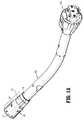
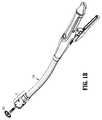
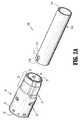
図1Aおよび図2Aを参照すると、ローディングユニット10が、本開示の実施形態に従って提供されている。ローディングユニット10は、外科手術器具の、アダプター102を有するアダプターアセンブリ100を介した動力式ハンドヘルド電気機械式器具(示されない)への選択的な接続のために構成されている。あるいは、ローディングユニット10は、手動で作動されるハンドルアセンブリまたはステープル留め器具700(図1B)への直接的な接続のために構成され得る(例えば、米国特許第8,789,737号(「’737特許」)に記載され、この米国特許は、本明細書中で参考として援用される)。例示される実施形態において、ローディングユニット10は、アダプター102の遠位端部分110に解放可能に結合されており、ステープルカートリッジ12(図4)と、シェルアセンブリ20と、係止カラー40とを含む。ローディングユニット10は、アンビル400(図1B)も含み得る。アダプター102は、ステープル留め器具(例えば、電気機械式器具(示されない))の動きを変換して、ステープルカートリッジ12を作動し、組織(示されない)を縫合および切断するように構成されている。アダプター102の近位端104は、ステープルカートリッジ12を作動するために、ステープル留め器具に取り付け可能である。アダプター102の近位端104は、ステープルカートリッジ12を作動するために、手動で作動される器具(例えば、’737特許に記載される)に取り付けられ得ることが企図される。 With reference to FIGS. 1A and 2A, a
例示的なアダプターおよびローディングユニットの構造および機能の詳細な記載について、2014年10月21日に出願された、共有に係る米国仮特許出願第62/066,518号を参照されたい。例示的な電気機械式器具の構造および機能の詳細な記載について、2012年5月31日に出願された、共有に係る米国特許出願第13/484,975号(現在、米国特許公開第2012/0253329号として公開されている)を参照されたい。これらの出願の各々は、本明細書中でその全体が参考として援用される。 For a detailed description of the structure and function of exemplary adapters and loading units, see co-owned US Provisional Patent Application No. 62 / 066,518, filed Oct. 21, 2014. For a detailed description of the structure and function of an exemplary electromechanical instrument, see US patent application Ser. No. 13 / 484,975 filed May 31, 2012 (currently US Pat. No. 0253329). Each of these applications is incorporated herein by reference in its entirety.
図2Aを参照すると、外科手術器具(例えば、アダプター102)の遠位端部分110は、ウインドー112を規定する。ウインドー112は、アダプター102の遠位端部分110の外側表面を通過しており、アダプター102の遠位端110aから間隔が置かれている。 With reference to FIG. 2A, the
図2Bも参照すると、シェルアセンブリ20は、アダプター102の遠位端部分110を受け取るための円筒形開口部21(図2A)を規定する近位端部分22と、ステープルカートリッジ12(図4)を受け取り、支持するためのレセプタクル34を規定する遠位端32とを含む。シェルアセンブリ20の近位端部分22は、溝24を規定する凹んだ環状リング23(図2B)を含み、この溝24は、係止カラー40を受け取るようなサイズにされている。実施形態において、係止カラー40は、係止カラー40がシェルアセンブリ20の近位端部分22の外側表面との連続的または滑らかな表面を形成するように、溝24の深さと等しい厚さを有する。環状リング23は、下で詳述されるように、係止カラー40の一部分を受け取るロック開口部28(図5)を規定し、内側表面23aおよび外側表面23bを規定する。 Referring also to FIG. 2B, the
シェルアセンブリ20の近位端部分22は、係止カラー40を溝24内に保持するカラーリテーナー25を支持している。カラーリテーナー25はまた、係止カラー40の外径からアダプター102(または代替的に、器具700(図1B))の遠位端部分110への滑らかな移行を提供するために、テーパ状にされ得る。カラーリテーナー25は、カラーリテーナー25をシェルアセンブリ20の近位端部分22に固定する係止特徴26(図2A)を含み得る。カラーリテーナー25が、任意の公知の手段(プレスばめまたは超音波溶接のタブ、およびインターロック構造が挙げられるが、これらに限定されない)によってシェルアセンブリ20の近位端部分22に固定され得ることが企図される。カラーリテーナー25が、シェルアセンブリ20の近位端部分22と一体的に形成され得ることも企図される。 The
図3〜図6も参照すると、係止カラー40は、シェルアセンブリ20の近位端部分22の溝24内に嵌るようなサイズにされている概して環状の本体42と、環状本体42から半径方向内方に延びているロック44とを含む。係止カラー40は、ロック44がロック開口部28と半径方向に整列されるように、近位端部分22の周りに位置決めされている。ロック44は、近位ステップ45と、遠位ステップ48と、近位ステップ45と遠位ステップ48との間に位置決めされている角度付き表面46とを含む。近位ステップ45は、シェルアセンブリ20の長手方向軸A−Aから第1の距離を半径方向内方に延びており、遠位ステップ48は、シェルアセンブリ20の長手方向軸A−Aから第1の距離よりも短い第2の距離を半径方向内方に延びている。ロック44は、角度付き表面46と遠位ステップ48との間にランディング47も含み得、このランディング47は、シェルアセンブリ20の長手方向軸A−Aに対して実質的に平行である。遠位ステップ48は、シェルアセンブリ20の環状リング23のロック開口部28を規定する遠位壁を係合するように位置決めされている。近位ステップ45は、係止カラー40をシェルアセンブリ20の近位端部分22に長手方向に固定するために、ロック開口部28の近位壁に隣接して位置決めされている。 Referring also to FIGS. 3-6, the locking
係止カラー40は、弾性材料から作製される。例えば、係止カラー12は、射出成形プロセスを用いて、弾性プラスチック材料から形成され得る。しかし、係止カラー40が他の適切な材料(ばね鋼、ステンレス鋼、またはワイヤーが挙げられるが、これらに限定されない)から形成され得ることが企図される。 The locking
図6を特に参照すると、係止カラー40は、第1の解放表面41aと第2の解放表面41bとを含み、ロック44は、第1の解放表面41aと第2の解放表面41bとの間の中間で環状本体42上に位置決めされている。係止された構成において、環状本体42は、概して楕円形の形状を規定し、ここで、環状本体42は、第1の軸B−Bに沿った幅(第1の解放表面41aから第2の解放表面41bまで)を有し、この幅は、第2の軸C−Cに沿ったその高さ(ロック44からロック44に対向している側面まで)よりも大きい。環状本体42は、環状リング23の周りに位置決めされている場合に、ロック44が、環状リング23(図5)の内側表面23aを貫通し、かつアダプター102の遠位端部分110のウインドー112の中に延びて、ローディングユニット10を外科手術器具(例えば、アダプター102)に固定するように、係止された構成に向かって付勢されている。環状本体42は、遠位ステップ48(図5)がアダプター102のウインドー112を規定する遠位壁112a(図5)を係合して、シェルアセンブリ20を外科手術器具のアダプター102の遠位端部分110に長手方向に固定するように、環状リング23の周りで溝24内に位置決めされている。シェルアセンブリ20の環状リング23のロック開口部28は、上で詳述されるように、ロック44がロック開口部28およびウインドー112を通過することを可能にするために、係止された構成において、アダプター102のウインドー112と整列されていることが認識される。 With particular reference to FIG. 6, the locking
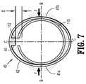
図7および図8は、係止されていない構成における係止カラー40を例示しており、環状本体42は、高さが幅よりも大きい概して楕円形の形状を規定している。解放表面41a、41bは、係止カラー40を係止されていない構成に移動するために、手動で一緒に押圧され得る。係止されていない構成において、ロック44は、ロック44が環状リング23(図5)の内側表面23aから半径方向外方に位置決めされるように、図7に示される距離「D」だけ半径方向外方に移動される。係止されていない構成において、係止カラー40が係止されていない構成にあるとき、ローディングユニット10が、アダプター102の遠位端部分110から係合解除され、取り外されるように、距離「D」は、ロック44がアダプター102のウインドー112の中に延びている距離よりも大きい。係止されていない構成において、ロック44がアダプター102のウインドー112、およびシェルアセンブリ20の近位端部分22のロック開口部28から取り外されるように、距離「D」は、ロック44の遠位ステップ48が半径方向内方に延びている第2の距離よりも大きくてもよいことが企図される。示されるように、係止されていない構成において、高さが幅よりも大きいが、係止されていない構成において、ロック44が距離「D」だけ外方に移動されている状態で、幅が高さよりも大きくてもよいことが企図される。 7 and 8 illustrate the locking
図2〜図4に戻って参照すると、ローディングユニット10を外科手術器具(例えば、アダプター102)に結合するために、ローディングユニット10は、アダプター102のウインドー112が環状リング23のロック開口部28および係止カラー40のロック44と半径方向に整列されて、アダプター102の遠位端部分110が近位端部分22の円筒形開口部21内に位置決めされるように、アダプター102と整列される。係止カラー40の外側表面は、ロック44の場所に関して、可視のしるしまたは触覚に基づくしるしを含み得る。ローディングユニット10がアダプター102と整列されている状態で、ローディングユニット10は、ロック44がアダプター102のウインドー112内に受け取られるまで、アダプター102の遠位端部分110上を近位方向に移動される。ロック44がロック開口部28を通過して、アダプター102のウインドー112内に受け取られていることが認識される。ローディングユニット10がアダプター102の遠位端部分110上を近位方向に移動される場合、ロック44の角度付き表面46は、ウインドー112がロック44との整列へ移動するまで、アダプター102の遠位端部分110を係合して、係止された構成から係止されていない構成に向かって、環状本体42の自然弾性に対抗して、係止カラー40を移行する(すなわち、変形させるようにカム作用を実施する)。ウインドー112がロック44との整列へ移動する場合、ロック44は、ウインドー112の中にスナップして嵌る。係止カラー40のスナップする動きは、ロック44がウインドー112内に受け取られているという可視のしるしまたは可聴のしるしを提供し得る。係止カラー40の環状本体42の自然弾性は、ロック44をアダプター102におけるウインドー112を通して押し付けていることが認識される。ロック44がウインドー112内に位置決めされている場合、係止カラー40の遠位ステップ48は、ウインドー112を規定するアダプター102の壁112aを係合して、ローディングユニット10のシェルアセンブリ20をアダプター102に長手方向に固定する。さらに、ロック44がウインドー112内に受け取られている場合、ロック44は、ローディングユニット10が外科手術器具(例えば、アダプター102)に対して回転すること、またはねじれることを防止する(すなわち、半径方向に固定する)。 Referring back to FIGS. 2-4, in order to couple the
ローディングユニット10が外科手術器具(例えば、アダプター102)に結合されている状態で、外科手術器具およびローディングユニット10は、外科手術手順を実施するために使用され得る。外科手術手順が完了した後、ローディングユニット10は、下で詳細に議論されるように、外科手術器具から分離され得るか、または外され得る。ローディングユニット10が外科手術器具から分離された状態で、別のローディングユニットが、外科手術手順における引き続きの使用のために外科手術器具に結合され得るか、外科手術器具が、別の外科手術手順における使用のために滅菌され得るか、または外科手術器具が、捨てられ得る。さらに、ローディングユニット10は、別の外科手術手順における使用のために滅菌され得るか、または捨てられ得る。 With the
ローディングユニット10を外科手術器具(例えば、アダプター102)から分離するか、または取り外すために、係止カラー40は、第1の解放表面41aおよび第2の解放表面41bを、図7に示される矢印「F」によって表されるように、第1の軸B−Bに沿って互いに向かって圧縮することによって、係止されていない構成に移行される。係止カラー40は、第1の解放表面41aおよび第2の解放表面41bのうちの一方のみを他方の解放表面41a、41bに向かって圧縮することによって、図7に示されるように、係止されていない構成に移行され得ることが企図される。係止カラー40が係止されていない構成にある状態で、シェルアセンブリ20は、シェルアセンブリ20をアダプター102に対して軸方向に移動することによって、アダプター102の遠位端部分110との係合から取り外され得る。 In order to separate or remove the
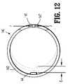
次に図9〜図12を参照すると、別の係止カラー140が、本開示に従って提供されており、ロック44と環状本体142とを含む。係止カラー140のロック44は、上で詳述される係止カラー40のロック44と実質的に同様であり、どのようにそれが係止カラー140に関連しているかを除いて、下でさらに議論される。係止カラー140の環状本体142は、上で詳述される係止カラー40の環状本体42と同様であり、従って、簡潔さのために、違いのみが下で詳述される。 With reference now to FIGS. 9-12, another
環状本体142は、下に記載されるように、一方の側で分けられて、第1の解放表面または端部分144および第2の解放表面または端部分146を形成し、これらは、互いに対して移動可能に位置決めされ、その結果、係止カラー140の直径は、選択的に変えられ得る。第1の端部分144は、環状本体142の周囲で第1の方向に延び、第2の端部分146は、環状本体142の周囲で第1の方向と反対の第2の方向に延びる。第1の解放表面144および第2の解放表面146は、ロック44に対向して、環状本体142の周りに位置決めされている。第1の端部分144および第2の端部分146の各々は、端145、147を有し、端145、147は、環状本体142に隣接している係合ウインドー149を規定する。第1の端部分144および第2の端部分146の各々は、第1の端部分144および第2の端部分146が環状本体142の周囲で互いにオーバーラップするように、ローディングユニット10(図1)の長手方向軸に沿って、環状本体142の厚さの約半分の厚さを有する。 The
特に図10および図12を参照すると、係止カラー140は、係止カラー140を係止された構成(図10)に向かって押し付ける自然弾性を有する弾性材料から形成されている。係止された構成において、環状本体142は、ローディングユニット10(図1)の長手方向軸に対して横断する面において、実質的に円形の断面を規定する。係止カラー140(図12)の係止されていない構成において、環状本体142は、ローディングユニット10の長手方向軸に対して横断する面において、概して楕円形の断面を規定する。係止されていない構成において、ロック44は、第1の端部分144および第2の端部分146から離れて距離「E」を移動される。係止カラー140は、矢印「F」によって表されるように、第1の端部分144の端145および第2の端部分146の端147を互いに向かって押し付けることによって、係止されていない構成に向かって移行される。端145、147が互いに向かって押し付けられると、環状本体142は、端145、147から離れて距離「E」の分、ロック44を移動する。第1の端部分144および第2の端部分146は、第1の端部分144および第2の端部分146を押し付けて係止カラー140を係止されていない構成に向かって移動する方向に関して、矢印(図9)の形態で可視のしるしまたは触覚に基づくしるしを含み得る。 With particular reference to FIGS. 10 and 12, the
本開示のいくつかの実施形態が図面に示されてきたが、本開示は当該分野が許容するのと同じくらい範囲が広いこと、および本明細書が同様に読まれることが意図されるので、本開示はそれらの実施形態に限定されることが意図されない。例えば、ロックリングの係止されていない位置において、ロックリングは、係止された位置における幅よりも小さい幅を規定し得、高さは、係止された位置における高さよりも大きい。特定の実施形態において、ロックリングの他の相対的な寸法が変わり、変化するアスペクト比を有するロックリングが使用され得る。 Although several embodiments of the present disclosure have been shown in the drawings, it is intended that the present disclosure be as broad as the field allows, and that the present specification is intended to be read similarly. The present disclosure is not intended to be limited to those embodiments. For example, in the unlocked position of the lock ring, the lock ring may define a width that is less than the width in the locked position, the height being greater than the height in the locked position. In certain embodiments, other relative dimensions of the lock ring can be varied and lock rings with varying aspect ratios can be used.
上の実施形態の任意の組み合わせも想定され、それは、添付の特許請求の範囲の範囲内である。本開示は、円形ステープル留めローディングユニットに限定されるものではなく、線形ステープル留め器具または他のタイプの器具(例えば、電気焼灼器具または超音波器具)のためのローディングユニットへの応用を有する。従って、上の記載は、限定するものではなく、単に特定の実施形態の例証と解釈されるべきである。当業者は、本明細書に添付される特許請求の範囲の範囲内で他の改変を想定する。 Any combination of the above embodiments is also contemplated and is within the scope of the appended claims. The present disclosure is not limited to circular stapling loading units, but has application to loading units for linear stapling instruments or other types of instruments (eg, electrocautery or ultrasonic instruments). Therefore, the above description should not be construed as limiting, but merely as exemplifications of particular embodiments. Those skilled in the art will envision other modifications within the scope of the claims appended hereto.
Claims (20)
Translated fromJapanese外科手術器具の遠位端部分を受け取るように構成されている近位端部分を有するシェルアセンブリであって、該近位端部分は、環状リングを含み、環状溝を規定し、該環状リングは、ロック開口部を規定する、シェルアセンブリと、
該環状溝内に解放可能に配置されている係止カラーと
を含み、該係止カラーは、環状本体を含み、該環状本体は、1対の解放表面とロックとを有し、該ロックは、該環状本体から半径方向内方に延びており、該1対の解放表面は、該係止カラーを、該ロックが該ロック開口部を通って延びて該環状リングの内側表面を貫通している係止された構成から、該ロックが該環状リングの該内側表面から半径方向外方に位置決めされている係止されていない構成に移行するように構成されている、ローディングユニットおよび係止カラーのアセンブリ。A loading unit and locking collar assembly,
A shell assembly having a proximal end portion configured to receive a distal end portion of a surgical instrument, the proximal end portion including an annular ring and defining an annular groove, the annular ring being A shell assembly defining a lock opening; and
A locking collar releasably disposed within the annular groove, the locking collar including an annular body, the annular body having a pair of release surfaces and a lock, the lock being Extending radially inward from the annular body, the pair of release surfaces extending the locking collar through the inner surface of the annular ring with the lock extending through the lock opening. A loading unit and a locking collar configured to transition from a locked configuration to an unlocked configuration in which the lock is positioned radially outward from the inner surface of the annular ring Assembly.
遠位端を含む外科手術器具と、
シェルアセンブリを含むローディングユニットであって、該シェルアセンブリは、近位端部分を有し、該シェルアセンブリの該近位端部分は、該外科手術器具の該遠位端上に位置決めされ、該シェルアセンブリの該近位端部分は、環状リングを含み、該近位端部分に環状溝を規定し、該環状リングは、ロック開口部を規定する、ローディングユニットと、
該ローディングユニットの該環状溝内に解放可能に配置されている係止カラーと
を含み、該係止カラーは、環状本体を含み、該環状本体は、1対の解放表面とロックとを有し、該ロックは、該環状本体から半径方向内方に延びており、該1対の解放表面は、該係止カラーを、該ロックが該ロック開口部を通って延びて該環状リングの内側表面を貫通している係止された構成から、該ロックが該環状リングの該内側表面から半径方向外方に位置決めされている係止されていない構成に移行するように構成されている、外科手術システム。A surgical system,
A surgical instrument including a distal end;
A loading unit including a shell assembly, the shell assembly having a proximal end portion, the proximal end portion of the shell assembly being positioned on the distal end of the surgical instrument and the shell The proximal end portion of the assembly includes an annular ring, defining an annular groove in the proximal end portion, the annular ring defining a locking opening;
A locking collar releasably disposed within the annular groove of the loading unit, the locking collar including an annular body, the annular body having a pair of release surfaces and a lock The lock extends radially inward from the annular body, the pair of release surfaces extending the locking collar and the lock extending through the lock opening to the inner surface of the annular ring. A surgical configuration configured to transition from a locked configuration penetrating through an unlocked configuration in which the lock is positioned radially outward from the inner surface of the annular ring. system.
Applications Claiming Priority (2)
| Application Number | Priority Date | Filing Date | Title |
|---|---|---|---|
| US14/591,193 | 2015-01-07 | ||
| US14/591,193US10022126B2 (en) | 2015-01-07 | 2015-01-07 | Loading unit locking collar |
Related Child Applications (1)
| Application Number | Title | Priority Date | Filing Date |
|---|---|---|---|
| JP2019206028ADivisionJP2020036943A (en) | 2015-01-07 | 2019-11-14 | Loading unit locking collar |
Publications (2)
| Publication Number | Publication Date |
|---|---|
| JP2016123854Atrue JP2016123854A (en) | 2016-07-11 |
| JP6792328B2 JP6792328B2 (en) | 2020-11-25 |
Family
ID=55070869
Family Applications (2)
| Application Number | Title | Priority Date | Filing Date |
|---|---|---|---|
| JP2015240912AExpired - Fee RelatedJP6792328B2 (en) | 2015-01-07 | 2015-12-10 | Loading unit locking collar |
| JP2019206028APendingJP2020036943A (en) | 2015-01-07 | 2019-11-14 | Loading unit locking collar |
Family Applications After (1)
| Application Number | Title | Priority Date | Filing Date |
|---|---|---|---|
| JP2019206028APendingJP2020036943A (en) | 2015-01-07 | 2019-11-14 | Loading unit locking collar |
Country Status (5)
| Country | Link |
|---|---|
| US (1) | US10022126B2 (en) |
| EP (1) | EP3042620B1 (en) |
| JP (2) | JP6792328B2 (en) |
| AU (1) | AU2015261592B2 (en) |
| CA (1) | CA2913039A1 (en) |
Families Citing this family (22)
| Publication number | Priority date | Publication date | Assignee | Title |
|---|---|---|---|---|
| CN104042292A (en) | 2013-03-15 | 2014-09-17 | 柯惠Lp公司 | Surgical anastomosis device comprising assemblies capable of being repeatedly utilized |
| US9730694B2 (en)* | 2014-07-01 | 2017-08-15 | Covidien Lp | Loading unit including shipping assembly |
| US10085744B2 (en)* | 2014-12-08 | 2018-10-02 | Covidien Lp | Loading unit attachment band for surgical stapling instrument |
| US10039549B2 (en)* | 2015-01-07 | 2018-08-07 | Covidien Lp | Loading unit retention clip for surgical stapling instrument |
| US10111665B2 (en)* | 2015-02-19 | 2018-10-30 | Covidien Lp | Electromechanical surgical systems |
| US10117655B2 (en) | 2015-07-22 | 2018-11-06 | Covidien Lp | Loading unit locking band for surgical stapling instrument |
| US9980730B2 (en)* | 2015-09-21 | 2018-05-29 | Covidien Lp | Loading unit locking collar with rotational actuated release |
| US10182813B2 (en)* | 2015-09-29 | 2019-01-22 | Ethicon Llc | Surgical stapling instrument with shaft release, powered firing, and powered articulation |
| US11141162B2 (en)* | 2016-07-08 | 2021-10-12 | Covidien Lp | Loading unit locking collar with linearly actuated release |
| EP3573543A4 (en) | 2017-01-25 | 2021-03-03 | Covidien LP | Circular stapling device and method of use |
| US10881409B2 (en) | 2017-05-02 | 2021-01-05 | Covidien Lp | Rotation assembly for a surgical device |
| US10617422B2 (en) | 2017-05-05 | 2020-04-14 | Covidien Lp | Snap ring cam actuator release for a loading unit |
| US10695069B2 (en) | 2017-08-23 | 2020-06-30 | Covidien Lp | Circular stapling device with offset spline tip |
| EP3675748B1 (en) | 2017-09-01 | 2024-06-12 | Covidien LP | Circular stapling device with position ribs |
| US11497501B2 (en) | 2018-03-26 | 2022-11-15 | Covidien Lp | Circular stapling device with A-frame splines |
| WO2020123169A1 (en) | 2018-12-14 | 2020-06-18 | Covidien Lp | Inserts, splines, and methods for reducing and/or eliminating spline crash in surgical instruments |
| US11324509B2 (en) | 2019-03-28 | 2022-05-10 | Covidien Lp | Spline crash correction with motor oscillation |
| WO2021245763A1 (en)* | 2020-06-01 | 2021-12-09 | オリンパス株式会社 | Treatment instrument |
| US20230000495A1 (en) | 2021-06-30 | 2023-01-05 | Covidien Lp | Circular stapling device with tissue grasping members |
| US11896231B2 (en)* | 2021-09-10 | 2024-02-13 | Cilag Gmbh International | Coupling feature for circular surgical stapler end effector |
| US11717299B2 (en) | 2021-10-12 | 2023-08-08 | Covidien Lp | Surgical stapling device with probiotics |
| US20230302620A1 (en)* | 2022-03-28 | 2023-09-28 | Milwaukee Electric Tool Corporation | Rotary power tool |
Citations (8)
| Publication number | Priority date | Publication date | Assignee | Title |
|---|---|---|---|---|
| JPS6025607U (en)* | 1983-07-29 | 1985-02-21 | 株式会社 東京衛材研究所 | surgical anastomosis device |
| US6193129B1 (en)* | 2000-01-24 | 2001-02-27 | Ethicon Endo-Surgery, Inc. | Cutting blade for a surgical anastomosis stapling instrument |
| JP2006336764A (en)* | 2005-06-02 | 2006-12-14 | Sanyo Kasei:Kk | Pipe joint |
| JP2009189844A (en)* | 2008-02-15 | 2009-08-27 | Ethicon Endo Surgery Inc | Disposable loading unit for surgical incision and stapling instrument |
| JP2011526804A (en)* | 2008-06-30 | 2011-10-20 | メドトロニック・ゾーメド・インコーポレーテッド | Chuck for reciprocating surgical instruments |
| US20120054979A1 (en)* | 2010-09-03 | 2012-03-08 | Dant Ryan T | Combined crevice tool and dusting brush |
| JP2013531509A (en)* | 2010-04-12 | 2013-08-08 | ベッチャー・インダストリーズ・インコーポレイテッド | Power driven rotary knife with disposable blade support assembly |
| WO2014139442A1 (en)* | 2013-03-15 | 2014-09-18 | Covidien Lp | Surgical fastener applying apparatus |
Family Cites Families (352)
| Publication number | Priority date | Publication date | Assignee | Title |
|---|---|---|---|---|
| CA908529A (en) | 1972-08-29 | V. Astafiev Georgy | Surgical instrument for suturing hollow organs in infants | |
| DE1057729B (en) | 1954-03-29 | 1959-05-21 | Lameris Instr N V | Surgical device for connecting two parts of the intestine |
| GB787043A (en) | 1954-09-15 | 1957-11-27 | Sylvania Electric Prod | Method for production of silicon |
| CA736256A (en) | 1962-08-27 | 1966-06-14 | S. Kasoolin Viacheslav | Instrument for suturing esophagus to intestine or stomach |
| FR1461464A (en) | 1965-08-20 | 1966-02-25 | Niiex Khirurgicheskoi Apparatu | Surgical device for suturing organs |
| CH470170A (en) | 1968-02-02 | 1969-03-31 | Vnii Khirurgicheskoi Apparatur | Device for applying round anastomoses |
| US3638652A (en) | 1970-06-01 | 1972-02-01 | James L Kelley | Surgical instrument for intraluminal anastomosis |
| US3771526A (en) | 1972-02-07 | 1973-11-13 | P Rudie | Anastomosis clamp |
| US4304236A (en) | 1977-05-26 | 1981-12-08 | United States Surgical Corporation | Stapling instrument having an anvil-carrying part of particular geometric shape |
| US4573468A (en) | 1977-05-26 | 1986-03-04 | United States Surgical Corporation | Hollow body organ stapling instrument and disposable cartridge employing relief vents |
| US4603693A (en)* | 1977-05-26 | 1986-08-05 | United States Surgical Corporation | Instrument for circular surgical stapling of hollow body organs and disposable cartridge therefor |
| NL7711347A (en) | 1977-10-17 | 1979-04-19 | Carl Robert Erik Daantje | Stapling instrument for joining intestine ends - has head coupling rod in two parts screwing together with hand grip |
| US4207898A (en) | 1978-03-27 | 1980-06-17 | Senco Products, Inc. | Intralumenal anastomosis surgical stapling instrument |
| US4198982A (en) | 1978-03-31 | 1980-04-22 | Memorial Hospital For Cancer And Allied Diseases | Surgical stapling instrument and method |
| DE2947107A1 (en) | 1978-12-07 | 1980-06-26 | United States Surgical Corp | ACCURATELY ALIGNED CARTRIDGE AND INSTRUMENT FOR CLAMPING ANASTOMOSES |
| SU1088712A1 (en) | 1979-11-14 | 1984-04-30 | Всесоюзный научно-исследовательский и испытательный институт медицинской техники | Apparatus for circular suture of blood vessels |
| AU534210B2 (en) | 1980-02-05 | 1984-01-12 | United States Surgical Corporation | Surgical staples |
| US4319576A (en) | 1980-02-26 | 1982-03-16 | Senco Products, Inc. | Intralumenal anastomosis surgical stapling instrument |
| US4289133A (en) | 1980-02-28 | 1981-09-15 | Senco Products, Inc. | Cut-through backup washer for the scalpel of an intraluminal surgical stapling instrument |
| US4606343A (en) | 1980-08-18 | 1986-08-19 | United States Surgical Corporation | Self-powered surgical fastening instrument |
| US4351466A (en) | 1980-10-16 | 1982-09-28 | United States Surgical Corporation | Disposable instrument for surgical fastening |
| US4379457A (en) | 1981-02-17 | 1983-04-12 | United States Surgical Corporation | Indicator for surgical stapler |
| US4476863A (en) | 1981-03-09 | 1984-10-16 | Kanshin Nikolai N | Surgical instrument for establishing circular coloanastomoses |
| US4632290A (en) | 1981-08-17 | 1986-12-30 | United States Surgical Corporation | Surgical stapler apparatus |
| US4576167A (en) | 1981-09-03 | 1986-03-18 | United States Surgical Corporation | Surgical stapler apparatus with curved shaft |
| SU1114405A1 (en) | 1982-02-23 | 1984-09-23 | Всесоюзный научно-исследовательский и испытательный институт медицинской техники | Surgical suturing apparatus for placing compression anastomoses on the organs of digestive tract |
| US4485817A (en) | 1982-05-28 | 1984-12-04 | United States Surgical Corporation | Surgical stapler apparatus with flexible shaft |
| US4473077A (en) | 1982-05-28 | 1984-09-25 | United States Surgical Corporation | Surgical stapler apparatus with flexible shaft |
| US4488523A (en) | 1982-09-24 | 1984-12-18 | United States Surgical Corporation | Flexible, hydraulically actuated device for applying surgical fasteners |
| DE3301713A1 (en) | 1983-01-20 | 1984-07-26 | Horst Dr. 3004 Isernhagen Ziegler | Surgical clip suture apparatus for producing circular joins |
| US4592354A (en) | 1983-10-11 | 1986-06-03 | Senmed, Inc. | Tissue retention spool for intraluminal anastomotic surgical stapling instrument and methods |
| US4505414A (en) | 1983-10-12 | 1985-03-19 | Filipi Charles J | Expandable anvil surgical stapler |
| US4550870A (en) | 1983-10-13 | 1985-11-05 | Alchemia Ltd. Partnership | Stapling device |
| IT1173284B (en) | 1984-02-16 | 1987-06-18 | Riccardo Rosati | CIRCULAR MECHANICAL STAPLING MACHINE |
| US4667673A (en) | 1984-03-12 | 1987-05-26 | American Cyanamid Company | Anastomotic device applicator and method |
| US4754909A (en) | 1984-08-09 | 1988-07-05 | Barker John M | Flexible stapler |
| US4671445A (en) | 1984-08-09 | 1987-06-09 | Baxter Travenol Laboratories, Inc. | Flexible surgical stapler assembly |
| US4665917A (en) | 1985-01-28 | 1987-05-19 | Ethicon, Inc. | Tissue gripper for use with intraluminal stapling device |
| US4703887A (en) | 1985-01-28 | 1987-11-03 | Ethicon, Inc. | Collapsible purse string aid for use with intraluminal stapling device |
| AU582625B2 (en) | 1985-01-28 | 1989-04-06 | Ethicon Inc. | Tissue gripper for use with intraluminal stapling device |
| JPS635697Y2 (en) | 1985-04-04 | 1988-02-17 | ||
| JPS62140776A (en) | 1985-12-16 | 1987-06-24 | 海老原 代師行 | Stapler |
| US4700703A (en) | 1986-03-27 | 1987-10-20 | Semion Resnick | Cartridge assembly for a surgical stapling instrument |
| US4903697A (en) | 1986-03-27 | 1990-02-27 | Semion Resnick | Cartridge assembly for a surgical stapling instrument |
| US4817847A (en) | 1986-04-21 | 1989-04-04 | Finanzaktiengesellschaft Globe Control | Instrument and a procedure for performing an anastomosis |
| US4917114A (en) | 1986-10-17 | 1990-04-17 | United States Surgical Corporation | Surgical fastener and surgical stapling apparatus |
| US4752024A (en) | 1986-10-17 | 1988-06-21 | Green David T | Surgical fastener and surgical stapling apparatus |
| US4776506A (en) | 1986-11-13 | 1988-10-11 | United States Surgical Corporation | Surgical stapler apparatus |
| US4873977A (en) | 1987-02-11 | 1989-10-17 | Odis L. Avant | Stapling method and apparatus for vesicle-urethral re-anastomosis following retropubic prostatectomy and other tubular anastomosis |
| US5119983A (en) | 1987-05-26 | 1992-06-09 | United States Surgical Corporation | Surgical stapler apparatus |
| US5285944A (en) | 1987-05-26 | 1994-02-15 | United States Surgical Corporation | Surgical stapler apparatus |
| US5158222A (en) | 1987-05-26 | 1992-10-27 | United States Surgical Corp. | Surgical stapler apparatus |
| SU1616624A1 (en) | 1987-07-14 | 1990-12-30 | Предприятие П/Я А-3697 | Surgical suturing apparatus |
| SU1509052A1 (en) | 1988-01-18 | 1989-09-23 | С. А. Попов | Surgical suturing apparatus |
| US4907591A (en) | 1988-03-29 | 1990-03-13 | Pfizer Hospital Products Group, Inc. | Surgical instrument for establishing compression anastomosis |
| US5193731A (en) | 1988-07-01 | 1993-03-16 | United States Surgical Corporation | Anastomosis surgical stapling instrument |
| US5005749A (en) | 1988-07-01 | 1991-04-09 | United States Surgical Corp. | Anastomosis surgical stapling instrument |
| ES2011110A6 (en) | 1988-09-02 | 1989-12-16 | Lopez Hervas Pedro | Hydraulic device with flexible body for surgical anastomosts |
| AU4742190A (en) | 1988-11-29 | 1990-06-26 | Bruce S. Gingold | Surgical stapling apparatus |
| US5197648A (en) | 1988-11-29 | 1993-03-30 | Gingold Bruce S | Surgical stapling apparatus |
| US4893662A (en) | 1988-12-06 | 1990-01-16 | Vito Gervasi | Cutting tool |
| US4930674A (en)* | 1989-02-24 | 1990-06-05 | Abiomed, Inc. | Surgical stapler |
| CH677728A5 (en) | 1989-10-17 | 1991-06-28 | Bieffe Medital Sa | |
| US5366462A (en) | 1990-08-28 | 1994-11-22 | Robert L. Kaster | Method of side-to-end vascular anastomotic stapling |
| US5047039A (en) | 1990-09-14 | 1991-09-10 | Odis Lynn Avant | Method and apparatus for effecting dorsal vein ligation and tubular anastomosis and laparoscopic prostatectomy |
| US5253793A (en) | 1990-09-17 | 1993-10-19 | United States Surgical Corporation | Apparatus for applying two-part surgical fasteners |
| US5104025A (en) | 1990-09-28 | 1992-04-14 | Ethicon, Inc. | Intraluminal anastomotic surgical stapler with detached anvil |
| US5042707A (en) | 1990-10-16 | 1991-08-27 | Taheri Syde A | Intravascular stapler, and method of operating same |
| CA2055943C (en) | 1990-12-06 | 2003-09-23 | Daniel P. Rodak | Surgical fastening apparatus with locking mechanism |
| US5122156A (en) | 1990-12-14 | 1992-06-16 | United States Surgical Corporation | Apparatus for securement and attachment of body organs |
| US5222963A (en) | 1991-01-17 | 1993-06-29 | Ethicon, Inc. | Pull-through circular anastomosic intraluminal stapler with absorbable fastener means |
| ATE135182T1 (en) | 1991-03-29 | 1996-03-15 | Perouse Implant Lab | SURGICAL STAPLE SEWING DEVICE |
| US5221036A (en) | 1991-06-11 | 1993-06-22 | Haruo Takase | Surgical stapler |
| US5350104A (en) | 1991-08-23 | 1994-09-27 | Ethicon, Inc. | Sealing means for endoscopic surgical anastomosis stapling instrument |
| US5333773A (en) | 1991-08-23 | 1994-08-02 | Ethicon, Inc. | Sealing means for endoscopic surgical anastomosis stapling instrument |
| GR920100358A (en) | 1991-08-23 | 1993-06-07 | Ethicon Inc | Surgical anastomosis stapling instrument. |
| US5474223A (en) | 1991-10-18 | 1995-12-12 | United States Surgical Corporation | Surgical fastener applying apparatus |
| US5443198A (en) | 1991-10-18 | 1995-08-22 | United States Surgical Corporation | Surgical fastener applying apparatus |
| US5197649A (en) | 1991-10-29 | 1993-03-30 | The Trustees Of Columbia University In The City Of New York | Gastrointestinal endoscoptic stapler |
| US5433721A (en) | 1992-01-17 | 1995-07-18 | Ethicon, Inc. | Endoscopic instrument having a torsionally stiff drive shaft for applying fasteners to tissue |
| US5188638A (en) | 1992-02-06 | 1993-02-23 | Tzakis Andreas G | Apparatus and method for preforming anastomosis fastener securement of hollow organs |
| US5271543A (en) | 1992-02-07 | 1993-12-21 | Ethicon, Inc. | Surgical anastomosis stapling instrument with flexible support shaft and anvil adjusting mechanism |
| US5348259A (en) | 1992-02-10 | 1994-09-20 | Massachusetts Institute Of Technology | Flexible, articulable column |
| US5425738A (en) | 1992-04-08 | 1995-06-20 | American Cyanamid Company | Endoscopic anastomosis ring insertion device and method of use thereof |
| US5282810A (en) | 1992-04-08 | 1994-02-01 | American Cyanamid Company | Surgical anastomosis device |
| US5355897A (en) | 1992-04-16 | 1994-10-18 | Ethicon, Inc. | Method of performing a pyloroplasty/pylorectomy using a stapler having a shield |
| US5314435A (en) | 1992-05-19 | 1994-05-24 | United States Surgical Corporation | Anvil delivery system |
| US5344059A (en) | 1992-05-19 | 1994-09-06 | United States Surgical Corporation | Surgical apparatus and anvil delivery system therefor |
| JPH0647050A (en) | 1992-06-04 | 1994-02-22 | Olympus Optical Co Ltd | Tissue suture and ligature device |
| US5658300A (en) | 1992-06-04 | 1997-08-19 | Olympus Optical Co., Ltd. | Tissue fixing surgical instrument, tissue-fixing device, and method of fixing tissues |
| US5360154A (en) | 1992-07-17 | 1994-11-01 | United States Surgical Corporation | Apparatus for creating partial anastomoses |
| US5330486A (en) | 1992-07-29 | 1994-07-19 | Wilk Peter J | Laparoscopic or endoscopic anastomosis technique and associated instruments |
| US5261920A (en) | 1992-08-21 | 1993-11-16 | Ethicon, Inc. | Anvil bushing for circular stapler |
| US5368215A (en) | 1992-09-08 | 1994-11-29 | United States Surgical Corporation | Surgical apparatus and detachable anvil rod therefor |
| US5309927A (en) | 1992-10-22 | 1994-05-10 | Ethicon, Inc. | Circular stapler tissue retention spring method |
| US5314436A (en) | 1992-10-30 | 1994-05-24 | Wilk Peter J | Method and apparatus for performing end-to-end anastomoses |
| US5404870A (en) | 1993-05-28 | 1995-04-11 | Ethicon, Inc. | Method of using a transanal inserter |
| US5503320A (en) | 1993-08-19 | 1996-04-02 | United States Surgical Corporation | Surgical apparatus with indicator |
| US5522534A (en) | 1993-10-01 | 1996-06-04 | United States Surgical Corporation | Anvil for surgical stapler |
| US5454825A (en) | 1993-10-01 | 1995-10-03 | United States Surgical Corporation | Circular anastomosis device with seal |
| US5447514A (en) | 1993-10-01 | 1995-09-05 | United States Surgical Corporation | Circular anastomosis device |
| US5437684A (en) | 1993-10-01 | 1995-08-01 | United States Surgical Corporation | Circular anastomosis device |
| CA2132917C (en) | 1993-10-07 | 2004-12-14 | John Charles Robertson | Circular anastomosis device |
| US5503635A (en) | 1993-11-12 | 1996-04-02 | United States Surgical Corporation | Apparatus and method for performing compressional anastomoses |
| DE4407668A1 (en) | 1994-03-09 | 1995-09-14 | Ferdinand Dr Koeckerling | Surgical anastomotic ring setting device |
| US5464415A (en) | 1994-03-15 | 1995-11-07 | Chen; Te-Chuan | Sutureless intestinal anastomosis gun |
| US5860581A (en) | 1994-03-24 | 1999-01-19 | United States Surgical Corporation | Anvil for circular stapler |
| US5715987A (en) | 1994-04-05 | 1998-02-10 | Tracor Incorporated | Constant width, adjustable grip, staple apparatus and method |
| CA2147800C (en) | 1994-05-26 | 2006-07-11 | John Charles Robertson | Circular anastomosis device |
| US5732872A (en) | 1994-06-17 | 1998-03-31 | Heartport, Inc. | Surgical stapling instrument |
| WO1995035065A1 (en) | 1994-06-17 | 1995-12-28 | Heartport, Inc. | Surgical stapling instrument and method thereof |
| US5881943A (en) | 1994-06-17 | 1999-03-16 | Heartport, Inc. | Surgical anastomosis apparatus and method thereof |
| CA2146508C (en) | 1994-08-25 | 2006-11-14 | Robert H. Schnut | Anvil for circular stapler |
| US5685474A (en) | 1994-10-04 | 1997-11-11 | United States Surgical Corporation | Tactile indicator for surgical instrument |
| US5868760A (en) | 1994-12-07 | 1999-02-09 | Mcguckin, Jr.; James F. | Method and apparatus for endolumenally resectioning tissue |
| US7235089B1 (en) | 1994-12-07 | 2007-06-26 | Boston Scientific Corporation | Surgical apparatus and method |
| US5720755A (en) | 1995-01-18 | 1998-02-24 | Dakov; Pepi | Tubular suturing device and methods of use |
| US5904697A (en) | 1995-02-24 | 1999-05-18 | Heartport, Inc. | Devices and methods for performing a vascular anastomosis |
| DE19509115C2 (en) | 1995-03-16 | 1997-11-27 | Deutsche Forsch Luft Raumfahrt | Surgical device for preparing an anastomosis using minimally invasive surgical techniques |
| US5769841A (en) | 1995-06-13 | 1998-06-23 | Electroscope, Inc. | Electrosurgical apparatus for laparoscopic and like procedures |
| US5641111A (en) | 1995-06-28 | 1997-06-24 | Ethicon Endo-Surgery, Inc. | Surgical stapling instrument with anvil cutting guide |
| US5749896A (en) | 1995-07-18 | 1998-05-12 | Cook; Melvin S. | Staple overlap |
| US5839639A (en) | 1995-08-17 | 1998-11-24 | Lasersurge, Inc. | Collapsible anvil assembly and applicator instrument |
| US5814055A (en) | 1995-09-19 | 1998-09-29 | Ethicon Endo-Surgery, Inc. | Surgical clamping mechanism |
| AU701033B2 (en) | 1995-10-31 | 1999-01-21 | Bernafon Ag | Method and anastomotic instrument for use when performing an end-to-side anastomosis |
| US5836503A (en) | 1996-04-22 | 1998-11-17 | United States Surgical Corporation | Insertion device for surgical apparatus |
| US6050472A (en) | 1996-04-26 | 2000-04-18 | Olympus Optical Co., Ltd. | Surgical anastomosis stapler |
| US6119913A (en) | 1996-06-14 | 2000-09-19 | Boston Scientific Corporation | Endoscopic stapler |
| US6440146B2 (en) | 1996-07-23 | 2002-08-27 | United States Surgical Corporation | Anastomosis instrument and method |
| US6024748A (en) | 1996-07-23 | 2000-02-15 | United States Surgical Corporation | Singleshot anastomosis instrument with detachable loading unit and method |
| US5833698A (en) | 1996-07-23 | 1998-11-10 | United States Surgical Corporation | Anastomosis instrument and method |
| US20020019642A1 (en) | 1996-07-23 | 2002-02-14 | Keith Milliman | Anastomosis instrument and method for performing same |
| US5855312A (en) | 1996-07-25 | 1999-01-05 | Toledano; Haviv | Flexible annular stapler for closed surgery of hollow organs |
| US5888200A (en) | 1996-08-02 | 1999-03-30 | Stryker Corporation | Multi-purpose surgical tool system |
| US6338737B1 (en) | 1997-07-17 | 2002-01-15 | Haviv Toledano | Flexible annular stapler for closed surgery of hollow organs |
| US5865361A (en) | 1997-09-23 | 1999-02-02 | United States Surgical Corporation | Surgical stapling apparatus |
| US6117148A (en) | 1997-10-17 | 2000-09-12 | Ravo; Biagio | Intraluminal anastomotic device |
| US5951576A (en) | 1998-03-02 | 1999-09-14 | Wakabayashi; Akio | End-to-side vascular anastomosing stapling device |
| US6279809B1 (en) | 1998-03-10 | 2001-08-28 | Enrico Nicolo | Circular stapler for side to end, side to side and end to side anastomosis |
| AU751697B2 (en) | 1998-05-11 | 2002-08-22 | Surgical Connections, Inc. | Devices and methods for treating e.g. urinary stress incontinence |
| US6517566B1 (en) | 1998-05-11 | 2003-02-11 | Surgical Connections, Inc. | Devices and methods for treating e.g. urinary stress incontinence |
| US6478210B2 (en) | 2000-10-25 | 2002-11-12 | Scimed Life Systems, Inc. | Method and device for full thickness resectioning of an organ |
| US6601749B2 (en) | 1998-06-19 | 2003-08-05 | Scimed Life Systems, Inc. | Multi fire full thickness resectioning device |
| US6126058A (en) | 1998-06-19 | 2000-10-03 | Scimed Life Systems, Inc. | Method and device for full thickness resectioning of an organ |
| US6585144B2 (en) | 1998-06-19 | 2003-07-01 | Acimed Life Systems, Inc. | Integrated surgical staple retainer for a full thickness resectioning device |
| US6629630B2 (en) | 1998-06-19 | 2003-10-07 | Scimed Life Systems, Inc. | Non-circular resection device and endoscope |
| DE19836950B4 (en) | 1998-08-17 | 2004-09-02 | Deutsches Zentrum für Luft- und Raumfahrt e.V. | Surgical instrument in the form of a suturing device |
| DE19837258A1 (en) | 1998-08-17 | 2000-03-02 | Deutsch Zentr Luft & Raumfahrt | Device for operating a surgical instrument for anastomosis of hollow organs |
| US6203553B1 (en) | 1999-09-08 | 2001-03-20 | United States Surgical | Stapling apparatus and method for heart valve replacement |
| US6102271A (en) | 1998-11-23 | 2000-08-15 | Ethicon Endo-Surgery, Inc. | Circular stapler for hemorrhoidal surgery |
| US6083241A (en) | 1998-11-23 | 2000-07-04 | Ethicon Endo-Surgery, Inc. | Method of use of a circular stapler for hemorrhoidal procedure |
| US6142933A (en) | 1998-11-23 | 2000-11-07 | Ethicon Endo-Surgery, Inc. | Anoscope for hemorrhoidal surgery |
| US6743244B2 (en) | 1999-04-16 | 2004-06-01 | Integrated Vascular Interventional Technologies, L.C. | Soft anvil apparatus for cutting anastomosis fenestra |
| US6652542B2 (en) | 1999-04-16 | 2003-11-25 | Integrated Vascular Interventional Technologies, L.C. (Ivit, Lc) | External anastomosis operators and related systems for anastomosis |
| US6626921B2 (en) | 1999-04-16 | 2003-09-30 | Integrated Vascular Interventional Technologies, L.C. | Externally positioned anvil apparatus for cutting anastomosis |
| US6551334B2 (en) | 1999-04-16 | 2003-04-22 | Integrated Vascular Interventional Technologies, Lc | Externally directed anastomosis systems and externally positioned anastomosis fenestra cutting apparatus |
| US6402008B1 (en) | 1999-04-19 | 2002-06-11 | Deborah A. Lucas | Surgical stapler assembly with interchangeable heads |
| US6068636A (en) | 1999-04-23 | 2000-05-30 | Chen; Te-Chuan | Intra-intestinal bypass gun |
| US6793652B1 (en) | 1999-06-02 | 2004-09-21 | Power Medical Interventions, Inc. | Electro-mechanical surgical device |
| US6716233B1 (en) | 1999-06-02 | 2004-04-06 | Power Medical Interventions, Inc. | Electromechanical driver and remote surgical instrument attachment having computer assisted control capabilities |
| US8025199B2 (en) | 2004-02-23 | 2011-09-27 | Tyco Healthcare Group Lp | Surgical cutting and stapling device |
| US7032798B2 (en) | 1999-06-02 | 2006-04-25 | Power Medical Interventions, Inc. | Electro-mechanical surgical device |
| US6491201B1 (en) | 2000-02-22 | 2002-12-10 | Power Medical Interventions, Inc. | Fluid delivery mechanism for use with anastomosing, stapling, and resecting instruments |
| US6264087B1 (en) | 1999-07-12 | 2001-07-24 | Powermed, Inc. | Expanding parallel jaw device for use with an electromechanical driver device |
| US6443973B1 (en) | 1999-06-02 | 2002-09-03 | Power Medical Interventions, Inc. | Electromechanical driver device for use with anastomosing, stapling, and resecting instruments |
| US6315184B1 (en) | 1999-06-02 | 2001-11-13 | Powermed, Inc. | Stapling device for use with an electromechanical driver device for use with anastomosing, stapling, and resecting instruments |
| US6981941B2 (en) | 1999-06-02 | 2006-01-03 | Power Medical Interventions | Electro-mechanical surgical device |
| AU2001232902B2 (en) | 2000-01-18 | 2004-07-08 | Covidien Lp | Anastomosis instrument and method for performing same |
| HU225908B1 (en) | 2000-01-24 | 2007-12-28 | Ethicon Endo Surgery Europe | Surgical circular stapling head |
| US6533157B1 (en) | 2000-02-22 | 2003-03-18 | Power Medical Interventions, Inc. | Tissue stapling attachment for use with an electromechanical driver device |
| US6488197B1 (en) | 2000-02-22 | 2002-12-03 | Power Medical Interventions, Inc. | Fluid delivery device for use with anastomosing resecting and stapling instruments |
| US6273897B1 (en) | 2000-02-29 | 2001-08-14 | Ethicon, Inc. | Surgical bettress and surgical stapling apparatus |
| DE60136862D1 (en) | 2000-03-06 | 2009-01-15 | Tyco Healthcare | DEVICE FOR IMPLEMENTING A BYPASS IN THE DIGESTING SYSTEM |
| IL139788A (en) | 2000-11-20 | 2006-10-05 | Minelu Zonnenschein | Stapler for endoscopes |
| US6592596B1 (en) | 2000-05-10 | 2003-07-15 | Scimed Life Systems, Inc. | Devices and related methods for securing a tissue fold |
| US20040267310A1 (en) | 2000-10-20 | 2004-12-30 | Racenet David C | Directionally biased staple and anvil assembly for forming the staple |
| US8286845B2 (en) | 2000-11-27 | 2012-10-16 | Boston Scientific Scimed, Inc. | Full thickness resection device control handle |
| US6821282B2 (en) | 2000-11-27 | 2004-11-23 | Scimed Life Systems, Inc. | Full thickness resection device control handle |
| US6398795B1 (en) | 2000-11-30 | 2002-06-04 | Scimed Life Systems, Inc. | Stapling and cutting in resectioning for full thickness resection devices |
| US6439446B1 (en) | 2000-12-01 | 2002-08-27 | Stephen J. Perry | Safety lockout for actuator shaft |
| US6503259B2 (en) | 2000-12-27 | 2003-01-07 | Ethicon, Inc. | Expandable anastomotic device |
| US6632237B2 (en) | 2001-01-11 | 2003-10-14 | Bio-Seal Tech, Inc. | Device and method for sealing a puncture in a blood vessel |
| EP1357844B1 (en) | 2001-01-24 | 2008-06-25 | Tyco Healthcare Group Lp | Anastomosis instrument and method for performing same |
| US6835199B2 (en) | 2001-01-31 | 2004-12-28 | Rex Medical, L.P. | Apparatus and method for resectioning gastro-esophageal tissue |
| US6769590B2 (en) | 2001-04-02 | 2004-08-03 | Susan E. Vresh | Luminal anastomotic device and method |
| EP2397080B1 (en) | 2001-04-03 | 2018-08-01 | Covidien LP | Surgical stapling device |
| US6632227B2 (en) | 2001-08-24 | 2003-10-14 | Scimed Life Systems, Inc. | Endoscopic resection devices |
| JP2005502421A (en) | 2001-09-17 | 2005-01-27 | ガルシア・ビセンテ ヒレテ | Craniotomy bone anchor |
| US6578751B2 (en) | 2001-09-26 | 2003-06-17 | Scimed Life Systems, Inc. | Method of sequentially firing staples using springs and a rotary or linear shutter |
| US20070060952A1 (en) | 2005-09-02 | 2007-03-15 | Roby Mark S | Surgical stapling device with coated knife blade |
| US6605098B2 (en) | 2001-09-28 | 2003-08-12 | Ethicon, Inc. | Surgical device for creating an anastomosis between first and second hollow organs |
| CA2462536C (en) | 2001-10-05 | 2010-03-30 | Tyco Healthcare Group Lp | Tilt top anvil for a surgical fastener device |
| US6605078B2 (en) | 2001-11-26 | 2003-08-12 | Scimed Life Systems, Inc. | Full thickness resection device |
| DE10158246C1 (en) | 2001-11-28 | 2003-08-21 | Ethicon Endo Surgery Europe | Surgical stapling instrument |
| US20030111507A1 (en) | 2001-12-14 | 2003-06-19 | George Nunez | Balloon actuator for use in a resectioning device |
| US6981979B2 (en) | 2001-12-14 | 2006-01-03 | Enrico Nicolo | Surgical anastomotic devices |
| US6905504B1 (en) | 2002-02-26 | 2005-06-14 | Cardica, Inc. | Tool for performing end-to-end anastomosis |
| US7128748B2 (en) | 2002-03-26 | 2006-10-31 | Synovis Life Technologies, Inc. | Circular stapler buttress combination |
| US7141055B2 (en) | 2002-04-24 | 2006-11-28 | Surgical Connections, Inc. | Resection and anastomosis devices and methods |
| WO2003090630A2 (en) | 2002-04-25 | 2003-11-06 | Tyco Healthcare Group, Lp | Surgical instruments including micro-electromechanical systems (mems) |
| US6685079B2 (en) | 2002-05-24 | 2004-02-03 | Scimed Life Systems, Inc. | Full thickness resectioning device |
| US6769594B2 (en) | 2002-05-31 | 2004-08-03 | Tyco Healthcare Group, Lp | End-to-end anastomosis instrument and method for performing same |
| US7195142B2 (en) | 2003-05-30 | 2007-03-27 | Tyco Healthcare Group Lp | End-to-end anastomosis instrument and method for performing same |
| EP1515645B1 (en) | 2002-06-17 | 2006-08-16 | Tyco Healthcare Group Lp | Annular support structures |
| IL150855A (en) | 2002-07-22 | 2007-06-03 | Leonid Monassevitch | Intratubular anastomosis apparatus |
| US6942620B2 (en) | 2002-09-20 | 2005-09-13 | Flowcardia Inc | Connector for securing ultrasound catheter to transducer |
| JP4422027B2 (en) | 2002-10-04 | 2010-02-24 | タイコ ヘルスケア グループ エルピー | Surgical stapling device |
| CA2500785C (en) | 2002-10-04 | 2011-04-26 | Philip C. Roy | Pneumatic powered surgical stapling device |
| US7220237B2 (en) | 2002-10-23 | 2007-05-22 | Satiety, Inc. | Method and device for use in endoscopic organ procedures |
| JP2006509595A (en) | 2002-12-16 | 2006-03-23 | エドリッチ・ヴァスキュラー・ディヴァイシズ,インコーポレイテッド | Multiple stapling instruments for narrow vessels |
| EP1572012B1 (en) | 2002-12-20 | 2008-08-20 | Tyco Healthcare Group Lp | Vacuum assisted surgical stapler |
| US6852122B2 (en) | 2003-01-23 | 2005-02-08 | Cordis Corporation | Coated endovascular AAA device |
| KR100547166B1 (en) | 2003-04-11 | 2006-01-26 | 허윤석 | Improved Short-Stage Anastomator |
| US8715303B2 (en) | 2003-06-06 | 2014-05-06 | Abbott Laboratories | Sizing and positioning adapter for medical instruments |
| EP1635712B1 (en) | 2003-06-20 | 2015-09-30 | Covidien LP | Surgical stapling device |
| CA2531909C (en) | 2003-07-16 | 2011-02-15 | Tyco Healthcare Group Lp | Surgical stapling device with tissue tensioner |
| US7686201B2 (en) | 2003-09-01 | 2010-03-30 | Tyco Healthcare Group Lp | Circular stapler for hemorrhoid operations |
| US7547312B2 (en) | 2003-09-17 | 2009-06-16 | Gore Enterprise Holdings, Inc. | Circular stapler buttress |
| US7309341B2 (en) | 2003-09-30 | 2007-12-18 | Ethicon Endo-Surgery, Inc. | Single lumen anastomosis applier for self-deploying fastener |
| EP1680028B1 (en) | 2003-10-17 | 2012-01-25 | Tyco Healthcare Group LP | Surgical stapling device |
| US9055943B2 (en) | 2007-09-21 | 2015-06-16 | Covidien Lp | Hand held surgical handle assembly, surgical adapters for use between surgical handle assembly and surgical end effectors, and methods of use |
| US7585306B2 (en) | 2003-12-24 | 2009-09-08 | Maquet Cardiovascular Llc | Anastomosis device, tools and methods of using |
| US8590764B2 (en) | 2003-12-24 | 2013-11-26 | Boston Scientific Scimed, Inc. | Circumferential full thickness resectioning device |
| US6953138B1 (en) | 2004-02-18 | 2005-10-11 | Frank W. Dworak | Surgical stapler anvil with nested staple forming pockets |
| US7086267B2 (en) | 2004-02-18 | 2006-08-08 | Frank W. Dworak | Metal-forming die and method for manufacturing same |
| US7118528B1 (en) | 2004-03-16 | 2006-10-10 | Gregory Piskun | Hemorrhoids treatment method and associated instrument assembly including anoscope and cofunctioning tissue occlusion device |
| US8181840B2 (en) | 2004-03-19 | 2012-05-22 | Tyco Healthcare Group Lp | Tissue tensioner assembly and approximation mechanism for surgical stapling device |
| ES2400050T3 (en) | 2004-03-19 | 2013-04-05 | Covidien Lp | Anvil set with improved cutting ring |
| WO2005115254A2 (en) | 2004-05-17 | 2005-12-08 | Datascope Investment Corp. | Surgical stapling system |
| JP4257270B2 (en) | 2004-07-14 | 2009-04-22 | オリンパス株式会社 | Biological tissue suturing method and biological tissue suturing device |
| US7410086B2 (en) | 2004-07-28 | 2008-08-12 | Ethicon Endo-Surgery, Inc. | Electroactive polymer-based actuation mechanism for circular stapler |
| US7182239B1 (en) | 2004-08-27 | 2007-02-27 | Myers Stephan R | Segmented introducer device for a circular surgical stapler |
| KR100646762B1 (en) | 2004-09-10 | 2006-11-23 | 인하대학교 산학협력단 | Surgical staples and surgical anastomosis device having the same |
| US8372094B2 (en) | 2004-10-15 | 2013-02-12 | Covidien Lp | Seal element for anastomosis |
| CA2583590C (en) | 2004-10-18 | 2013-05-07 | Tyco Healthcare Group, Lp | Compression anastomosis device and method |
| WO2006044494A2 (en) | 2004-10-18 | 2006-04-27 | Tyco Healthcare Group, Lp | Adhesive suture structure and methods of using the same |
| US7823592B2 (en) | 2004-10-18 | 2010-11-02 | Tyco Healthcare Group Lp | Annular adhesive structure |
| US7938307B2 (en) | 2004-10-18 | 2011-05-10 | Tyco Healthcare Group Lp | Support structures and methods of using the same |
| US7922743B2 (en) | 2004-10-18 | 2011-04-12 | Tyco Healthcare Group Lp | Structure for applying sprayable wound treatment material |
| US7455682B2 (en) | 2004-10-18 | 2008-11-25 | Tyco Healthcare Group Lp | Structure containing wound treatment material |
| US7717313B2 (en) | 2004-10-18 | 2010-05-18 | Tyco Healthcare Group Lp | Surgical apparatus and structure for applying sprayable wound treatment material |
| US7845536B2 (en) | 2004-10-18 | 2010-12-07 | Tyco Healthcare Group Lp | Annular adhesive structure |
| ITMI20042132A1 (en) | 2004-11-05 | 2005-02-05 | Ethicon Endo Surgery Inc | DEVICE AND METHOD FOR OBESITY THERAPY |
| US7207168B2 (en) | 2004-11-19 | 2007-04-24 | The Schnipke Family Limited Liability Company | Apparatus and method for inserting staple drivers in a cartridge |
| EP1847225B1 (en) | 2005-01-26 | 2011-12-21 | Suzhou Touchstone International Medical Science Co., Ltd. | Surgical stapler having a stapling head with a rotatable cutter |
| US20060201989A1 (en) | 2005-03-11 | 2006-09-14 | Ojeda Herminio F | Surgical anvil and system for deploying the same |
| US9364229B2 (en) | 2005-03-15 | 2016-06-14 | Covidien Lp | Circular anastomosis structures |
| US7717312B2 (en) | 2005-06-03 | 2010-05-18 | Tyco Healthcare Group Lp | Surgical instruments employing sensors |
| US8627995B2 (en) | 2006-05-19 | 2014-01-14 | Ethicon Endo-Sugery, Inc. | Electrically self-powered surgical instrument with cryptographic identification of interchangeable part |
| US7959050B2 (en) | 2005-07-26 | 2011-06-14 | Ethicon Endo-Surgery, Inc | Electrically self-powered surgical instrument with manual release |
| US8573462B2 (en) | 2006-05-19 | 2013-11-05 | Ethicon Endo-Surgery, Inc. | Electrical surgical instrument with optimized power supply and drive |
| US20070029363A1 (en) | 2005-08-07 | 2007-02-08 | Sergey Popov | Surgical apparatus with remote drive |
| US7398908B2 (en) | 2005-08-15 | 2008-07-15 | Tyco Healthcare Group Lp | Surgical stapling instruments including a cartridge having multiple staple sizes |
| US8579178B2 (en) | 2005-08-15 | 2013-11-12 | Covidien Lp | Surgical stapling instruments including a cartridge having multiple staples sizes |
| US7407075B2 (en) | 2005-08-15 | 2008-08-05 | Tyco Healthcare Group Lp | Staple cartridge having multiple staple sizes for a surgical stapling instrument |
| US7401721B2 (en) | 2005-08-15 | 2008-07-22 | Tyco Healthcare Group Lp | Surgical stapling instruments including a cartridge having multiple staple sizes |
| US7771440B2 (en) | 2005-08-18 | 2010-08-10 | Ethicon Endo-Surgery, Inc. | Method and apparatus for endoscopically performing gastric reduction surgery in a single pass |
| US7673781B2 (en) | 2005-08-31 | 2010-03-09 | Ethicon Endo-Surgery, Inc. | Surgical stapling device with staple driver that supports multiple wire diameter staples |
| CN2868208Y (en) | 2005-12-14 | 2007-02-14 | 苏州天臣国际医疗科技有限公司 | Round Tube Binding Instrument with Automatic Safety Mechanism |
| US7422138B2 (en) | 2006-02-01 | 2008-09-09 | Ethicon Endo-Surgery, Inc. | Elliptical intraluminal surgical stapler for anastomosis |
| US7793813B2 (en) | 2006-02-28 | 2010-09-14 | Tyco Healthcare Group Lp | Hub for positioning annular structure on a surgical device |
| US20100019016A1 (en) | 2006-03-23 | 2010-01-28 | Edoga John K | Vascular Anastomotic Staplers |
| DE102006016211A1 (en) | 2006-04-03 | 2007-10-04 | Novalung Gmbh | Cannula`s coupling, has socket and/or plug comprising opening, so that opening connects channel for providing fluid in environment in one resting position, and isolating fluid from environment in another resting position |
| DE602006010845D1 (en) | 2006-07-07 | 2010-01-14 | Ethicon Endo Surgery Inc | Surgical stapling device |
| US7527185B2 (en) | 2006-07-12 | 2009-05-05 | Niti Surgical Solutions Ltd. | Compression anastomosis ring assembly and applicator for use therewith |
| US7506791B2 (en) | 2006-09-29 | 2009-03-24 | Ethicon Endo-Surgery, Inc. | Surgical stapling instrument with mechanical mechanism for limiting maximum tissue compression |
| US7866525B2 (en) | 2006-10-06 | 2011-01-11 | Tyco Healthcare Group Lp | Surgical instrument having a plastic surface |
| US7753246B2 (en) | 2007-01-31 | 2010-07-13 | Tyco Healthcare Group Lp | Surgical instrument with replaceable loading unit |
| JP5070300B2 (en) | 2007-03-07 | 2012-11-07 | コヴィディエン・アクチェンゲゼルシャフト | Mucosal resection stapler |
| US7673782B2 (en) | 2007-03-15 | 2010-03-09 | Ethicon Endo-Surgery, Inc. | Surgical stapling instrument having a releasable buttress material |
| US7978403B2 (en) | 2007-05-10 | 2011-07-12 | Stc.Unm | Imaging interferometric microscopy |
| US8038045B2 (en) | 2007-05-25 | 2011-10-18 | Tyco Healthcare Group Lp | Staple buttress retention system |
| US7600663B2 (en) | 2007-07-05 | 2009-10-13 | Green David T | Apparatus for stapling and incising tissue |
| US7967181B2 (en) | 2007-08-29 | 2011-06-28 | Tyco Healthcare Group Lp | Rotary knife cutting systems |
| US20090082785A1 (en) | 2007-09-24 | 2009-03-26 | Milliman Keith L | Anvil Delivery Device Accessory |
| US8011554B2 (en) | 2008-01-09 | 2011-09-06 | Tyco Healthcare Group, Lp | Raised boss for staple guide |
| US8733611B2 (en) | 2008-03-12 | 2014-05-27 | Covidien Lp | Ratcheting mechanism for surgical stapling device |
| US8020741B2 (en) | 2008-03-18 | 2011-09-20 | Barosense, Inc. | Endoscopic stapling devices and methods |
| US8231041B2 (en) | 2008-04-14 | 2012-07-31 | Tyco Healthcare Group Lp | Variable compression surgical fastener cartridge |
| US8640940B2 (en) | 2008-04-30 | 2014-02-04 | Educational Foundation Jichi Medical University | Surgical system and surgical method for natural orifice transluminal endoscopic surgery (NOTES) |
| US8011551B2 (en) | 2008-07-01 | 2011-09-06 | Tyco Healthcare Group Lp | Retraction mechanism with clutch-less drive for use with a surgical apparatus |
| US8678264B2 (en) | 2008-07-07 | 2014-03-25 | Covidien Lp | Surgical instrument with elongated channel |
| US8109426B2 (en) | 2008-08-12 | 2012-02-07 | Tyco Healthcare Group Lp | Surgical tilt anvil assembly |
| US8672931B2 (en) | 2008-08-18 | 2014-03-18 | 3JT Enterprises, LLC | Cryosurgical device with metered dose |
| US8113405B2 (en) | 2008-09-03 | 2012-02-14 | Tyco Healthcare Group, Lp | Surgical instrument with indicator |
| US20100051668A1 (en) | 2008-09-03 | 2010-03-04 | Milliman Keith L | Surgical instrument with indicator |
| US8181838B2 (en) | 2008-09-10 | 2012-05-22 | Tyco Healthcare Group Lp | Surgical stapling device |
| US7837080B2 (en) | 2008-09-18 | 2010-11-23 | Ethicon Endo-Surgery, Inc. | Surgical stapling instrument with device for indicating when the instrument has cut through tissue |
| US20100084453A1 (en) | 2008-10-03 | 2010-04-08 | Changzhou Waston Medical Appliance Co., Ltd | Circular stapler |
| US7918377B2 (en) | 2008-10-16 | 2011-04-05 | Ethicon Endo-Surgery, Inc. | Surgical stapling instrument with apparatus for providing anvil position feedback |
| US8231042B2 (en) | 2008-11-06 | 2012-07-31 | Tyco Healthcare Group Lp | Surgical stapler |
| US7886951B2 (en) | 2008-11-24 | 2011-02-15 | Tyco Healthcare Group Lp | Pouch used to deliver medication when ruptured |
| US8770460B2 (en) | 2008-12-23 | 2014-07-08 | George E. Belzer | Shield for surgical stapler and method of use |
| US8408441B2 (en) | 2009-01-06 | 2013-04-02 | Covidien Lp | Surgical stapler |
| US8066167B2 (en) | 2009-03-23 | 2011-11-29 | Ethicon Endo-Surgery, Inc. | Circular surgical stapling instrument with anvil locking system |
| US8418909B2 (en) | 2009-06-02 | 2013-04-16 | Covidien Lp | Surgical instrument and method for performing a resection |
| US8276802B2 (en) | 2009-07-11 | 2012-10-02 | Tyco Healthcare Group Lp | Surgical instrument with double cartridge and anvil assemblies |
| US8146790B2 (en) | 2009-07-11 | 2012-04-03 | Tyco Healthcare Group Lp | Surgical instrument with safety mechanism |
| US20110011916A1 (en) | 2009-07-16 | 2011-01-20 | New York University | Anastomosis device |
| US8328062B2 (en) | 2009-07-21 | 2012-12-11 | Covidien Lp | Surgical instrument with curvilinear tissue-contacting surfaces |
| CN201481477U (en) | 2009-07-25 | 2010-05-26 | 冯志凌 | Ring-cutting anastomat for surgical operation |
| US8267301B2 (en) | 2009-08-19 | 2012-09-18 | Tyco Healthcare Group Lp | Surgical stapler |
| HU229773B1 (en) | 2009-09-02 | 2014-06-30 | A tool for surgical intervention | |
| EP2494913B1 (en) | 2009-10-26 | 2018-12-12 | B. J. Zh. F. Panther Medical Equipment Co., Ltd. | Anorectal surgical instrument and anal dilator |
| US8430292B2 (en) | 2009-10-28 | 2013-04-30 | Covidien Lp | Surgical fastening apparatus |
| US8322590B2 (en) | 2009-10-28 | 2012-12-04 | Covidien Lp | Surgical stapling instrument |
| US8413872B2 (en) | 2009-10-28 | 2013-04-09 | Covidien Lp | Surgical fastening apparatus |
| US20110114697A1 (en) | 2009-11-19 | 2011-05-19 | Ethicon Endo-Surgery, Inc. | Circular stapler introducer with multi-lumen sheath |
| US8136712B2 (en) | 2009-12-10 | 2012-03-20 | Ethicon Endo-Surgery, Inc. | Surgical stapler with discrete staple height adjustment and tactile feedback |
| US8328061B2 (en) | 2010-02-02 | 2012-12-11 | Covidien Lp | Surgical instrument for joining tissue |
| CN102188271B (en) | 2010-03-08 | 2012-10-10 | 北京中法派尔特医疗设备有限公司 | Nail anvil assembly capable of falling sideways and resetting, and stapler using the anvil assembly |
| US8662370B2 (en) | 2010-04-08 | 2014-03-04 | Hidehisa Thomas Takei | Introducer system and assembly for surgical staplers |
| US8783543B2 (en) | 2010-07-30 | 2014-07-22 | Ethicon Endo-Surgery, Inc. | Tissue acquisition arrangements and methods for surgical stapling devices |
| US8360296B2 (en) | 2010-09-09 | 2013-01-29 | Ethicon Endo-Surgery, Inc. | Surgical stapling head assembly with firing lockout for a surgical stapler |
| US8998061B2 (en) | 2010-10-01 | 2015-04-07 | Covidien Lp | Surgical fastener applying apparatus |
| US20120145755A1 (en) | 2010-12-14 | 2012-06-14 | Pk Products, Llc | Tool securing device and methods related thereto |
| US8496157B2 (en) | 2011-02-18 | 2013-07-30 | Covidien Lp | Tilting anvil for annular surgical stapler |
| US8479968B2 (en) | 2011-03-10 | 2013-07-09 | Covidien Lp | Surgical instrument buttress attachment |
| US8789737B2 (en) | 2011-04-27 | 2014-07-29 | Covidien Lp | Circular stapler and staple line reinforcement material |
| US9649113B2 (en) | 2011-04-27 | 2017-05-16 | Covidien Lp | Device for monitoring physiological parameters in vivo |
| US8490850B2 (en) | 2011-04-29 | 2013-07-23 | Covidien Lp | Circular stapler with controlled tissue compression |
| US8733615B2 (en) | 2011-05-19 | 2014-05-27 | Ethicon Endo-Surgery, Inc. | Circular stapler with frictional reducing member |
| US20130060258A1 (en) | 2011-08-26 | 2013-03-07 | Carman Giacomantonio | Endoluminal Surgical Instrument for Stapling, Cutting and Dividing |
| US9016547B2 (en) | 2011-10-26 | 2015-04-28 | Covidien Lp | EEA tilt top anvil with ratchet/locking mechanism |
| US9561347B2 (en) | 2011-11-16 | 2017-02-07 | W. L. Gore & Associates, Inc. | Introducer sheath assembly having a locking dilator |
| US9113885B2 (en) | 2011-12-14 | 2015-08-25 | Covidien Lp | Buttress assembly for use with surgical stapling device |
| US9010608B2 (en) | 2011-12-14 | 2015-04-21 | Covidien Lp | Releasable buttress retention on a surgical stapler |
| US8967448B2 (en) | 2011-12-14 | 2015-03-03 | Covidien Lp | Surgical stapling apparatus including buttress attachment via tabs |
| US9351731B2 (en) | 2011-12-14 | 2016-05-31 | Covidien Lp | Surgical stapling apparatus including releasable surgical buttress |
| US9220505B2 (en) | 2011-12-16 | 2015-12-29 | Ethicon Endo-Surgery, Inc. | Surgical stapling instrument with locking feature to lock anvil actuator |
| US9603599B2 (en) | 2011-12-16 | 2017-03-28 | Ethicon Endo-Surgery, Llc | Feature to reengage safety switch of tissue stapler |
| US9095340B2 (en) | 2012-01-05 | 2015-08-04 | Ethicon Endo-Surgery, Inc. | Tissue stapler safety switch feature to prevent premature jaw opening |
| US9549738B2 (en) | 2012-01-05 | 2017-01-24 | Ethicon Endo-Surgery, Llc | Ratcheting feature on tissue staple trigger to prevent premature jaw opening |
| US9186148B2 (en) | 2012-01-05 | 2015-11-17 | Ethicon Endo-Surgery, Inc. | Tissue stapler anvil feature to prevent premature jaw opening |
| US20130175315A1 (en) | 2012-01-11 | 2013-07-11 | Covidien Lp | Method and device for performing a surgical anastomosis |
| US9168042B2 (en) | 2012-01-12 | 2015-10-27 | Covidien Lp | Circular stapling instruments |
| US9010605B2 (en) | 2012-01-12 | 2015-04-21 | Covidien Lp | Sliding sleeve for circular stapling instrument reloads |
| US9010609B2 (en) | 2012-01-26 | 2015-04-21 | Covidien Lp | Circular stapler including buttress |
| US9326773B2 (en) | 2012-01-26 | 2016-05-03 | Covidien Lp | Surgical device including buttress material |
| US9010612B2 (en) | 2012-01-26 | 2015-04-21 | Covidien Lp | Buttress support design for EEA anvil |
| US9038882B2 (en) | 2012-02-03 | 2015-05-26 | Covidien Lp | Circular stapling instrument |
| US9022274B2 (en) | 2012-02-15 | 2015-05-05 | Covidien Lp | Circular stapler with increased lumen diameter |
| US20130284792A1 (en) | 2012-04-26 | 2013-10-31 | Covidien Lp | Surgical Stapling Device Including A Camera |
| US10213205B2 (en) | 2012-07-06 | 2019-02-26 | Covidien Lp | T-slot tilt anvil for circular stapling instrument |
| US10561432B2 (en) | 2013-03-05 | 2020-02-18 | Covidien Lp | Pivoting screw for use with a pair of jaw members of a surgical instrument |
| CN104042290A (en) | 2013-03-15 | 2014-09-17 | 柯惠Lp公司 | Operation anastomosis device |
| CN104042288A (en) | 2013-03-15 | 2014-09-17 | 柯惠Lp公司 | Operation anastomosis device |
| CN104042292A (en) | 2013-03-15 | 2014-09-17 | 柯惠Lp公司 | Surgical anastomosis device comprising assemblies capable of being repeatedly utilized |
| AU2014250896B2 (en) | 2013-04-11 | 2018-11-15 | Faculty Physicians And Surgeons Of Loma Linda University School Of Medicine | Minimally invasive surgical devices and methods |
| US10463365B2 (en) | 2013-10-17 | 2019-11-05 | Covidien Lp | Chip assembly for surgical instruments |
| US9913643B2 (en) | 2014-05-09 | 2018-03-13 | Covidien Lp | Interlock assemblies for replaceable loading unit |
| US10039549B2 (en) | 2015-01-07 | 2018-08-07 | Covidien Lp | Loading unit retention clip for surgical stapling instrument |
- 2015
- 2015-01-07USUS14/591,193patent/US10022126B2/enactiveActive
- 2015-11-24CACA2913039Apatent/CA2913039A1/ennot_activeAbandoned
- 2015-11-25AUAU2015261592Apatent/AU2015261592B2/ennot_activeCeased
- 2015-12-10JPJP2015240912Apatent/JP6792328B2/ennot_activeExpired - Fee Related
- 2016
- 2016-01-06EPEP16150288.5Apatent/EP3042620B1/enactiveActive
- 2019
- 2019-11-14JPJP2019206028Apatent/JP2020036943A/enactivePending
Patent Citations (8)
| Publication number | Priority date | Publication date | Assignee | Title |
|---|---|---|---|---|
| JPS6025607U (en)* | 1983-07-29 | 1985-02-21 | 株式会社 東京衛材研究所 | surgical anastomosis device |
| US6193129B1 (en)* | 2000-01-24 | 2001-02-27 | Ethicon Endo-Surgery, Inc. | Cutting blade for a surgical anastomosis stapling instrument |
| JP2006336764A (en)* | 2005-06-02 | 2006-12-14 | Sanyo Kasei:Kk | Pipe joint |
| JP2009189844A (en)* | 2008-02-15 | 2009-08-27 | Ethicon Endo Surgery Inc | Disposable loading unit for surgical incision and stapling instrument |
| JP2011526804A (en)* | 2008-06-30 | 2011-10-20 | メドトロニック・ゾーメド・インコーポレーテッド | Chuck for reciprocating surgical instruments |
| JP2013531509A (en)* | 2010-04-12 | 2013-08-08 | ベッチャー・インダストリーズ・インコーポレイテッド | Power driven rotary knife with disposable blade support assembly |
| US20120054979A1 (en)* | 2010-09-03 | 2012-03-08 | Dant Ryan T | Combined crevice tool and dusting brush |
| WO2014139442A1 (en)* | 2013-03-15 | 2014-09-18 | Covidien Lp | Surgical fastener applying apparatus |
Also Published As
| Publication number | Publication date |
|---|---|
| AU2015261592A1 (en) | 2016-07-21 |
| CA2913039A1 (en) | 2016-07-07 |
| JP2020036943A (en) | 2020-03-12 |
| JP6792328B2 (en) | 2020-11-25 |
| EP3042620A3 (en) | 2016-07-27 |
| EP3042620B1 (en) | 2018-10-10 |
| EP3042620A2 (en) | 2016-07-13 |
| US20160192938A1 (en) | 2016-07-07 |
| AU2015261592B2 (en) | 2020-03-19 |
| US10022126B2 (en) | 2018-07-17 |
Similar Documents
| Publication | Publication Date | Title |
|---|---|---|
| JP2020036943A (en) | Loading unit locking collar | |
| US10117656B2 (en) | Loading unit locking collar | |
| US10751049B2 (en) | Loading unit attachment band for surgical stapling instrument | |
| JP6609470B2 (en) | Loading unit retaining clip for surgical stapling instrument | |
| US11553917B2 (en) | Loading unit locking collar with rotational actuated release | |
| JP6400290B2 (en) | Circular stapling instrument | |
| US9532780B2 (en) | EEA anvil snap ring activator | |
| JP2014237028A (en) | Surgical fastening apparatus | |
| JP2017029704A (en) | Trocar tip protector | |
| EP3461429A1 (en) | Stapling device with resettable tilt anvil assembly | |
| US11147561B2 (en) | Reload assembly for a circular stapling device | |
| JP6758115B2 (en) | Loading unit locking collar |
Legal Events
| Date | Code | Title | Description |
|---|---|---|---|
| A621 | Written request for application examination | Free format text:JAPANESE INTERMEDIATE CODE: A621 Effective date:20181031 | |
| A977 | Report on retrieval | Free format text:JAPANESE INTERMEDIATE CODE: A971007 Effective date:20190814 | |
| A131 | Notification of reasons for refusal | Free format text:JAPANESE INTERMEDIATE CODE: A131 Effective date:20190820 | |
| A521 | Request for written amendment filed | Free format text:JAPANESE INTERMEDIATE CODE: A523 Effective date:20191114 | |
| A131 | Notification of reasons for refusal | Free format text:JAPANESE INTERMEDIATE CODE: A131 Effective date:20200421 | |
| A521 | Request for written amendment filed | Free format text:JAPANESE INTERMEDIATE CODE: A523 Effective date:20200612 | |
| TRDD | Decision of grant or rejection written | ||
| A01 | Written decision to grant a patent or to grant a registration (utility model) | Free format text:JAPANESE INTERMEDIATE CODE: A01 Effective date:20201030 | |
| A61 | First payment of annual fees (during grant procedure) | Free format text:JAPANESE INTERMEDIATE CODE: A61 Effective date:20201106 | |
| R150 | Certificate of patent or registration of utility model | Ref document number:6792328 Country of ref document:JP Free format text:JAPANESE INTERMEDIATE CODE: R150 | |
| R250 | Receipt of annual fees | Free format text:JAPANESE INTERMEDIATE CODE: R250 | |
| LAPS | Cancellation because of no payment of annual fees |