Movatterモバイル変換


[0]ホーム

URL:


JP2016122674A - Piezoelectric actuator - Google Patents

Piezoelectric actuator
Download PDF

Info

Publication number
JP2016122674A
JP2016122674AJP2014259914AJP2014259914AJP2016122674AJP 2016122674 AJP2016122674 AJP 2016122674AJP 2014259914 AJP2014259914 AJP 2014259914AJP 2014259914 AJP2014259914 AJP 2014259914AJP 2016122674 AJP2016122674 AJP 2016122674A
Authority
JP
Japan
Prior art keywords
piezoelectric element
piezoelectric
longitudinal direction
main surface
piezoelectric body
Prior art date
Legal status (The legal status is an assumption and is not a legal conclusion. Google has not performed a legal analysis and makes no representation as to the accuracy of the status listed.)
Granted
Application number
JP2014259914A
Other languages
Japanese (ja)
Other versions
JP6439438B2 (en
JP6439438B6 (en
Inventor
佳生 池田
Yoshio Ikeda
佳生 池田
一夫 永田
Kazuo Nagata
一夫 永田
貴大 毛塚
Takahiro Kezuka
貴大 毛塚
Current Assignee (The listed assignees may be inaccurate. Google has not performed a legal analysis and makes no representation or warranty as to the accuracy of the list.)
TDK Corp
Original Assignee
TDK Corp
Priority date (The priority date is an assumption and is not a legal conclusion. Google has not performed a legal analysis and makes no representation as to the accuracy of the date listed.)
Filing date
Publication date
Application filed by TDK CorpfiledCriticalTDK Corp
Priority to JP2014259914ApriorityCriticalpatent/JP6439438B6/en
Publication of JP2016122674ApublicationCriticalpatent/JP2016122674A/en
Publication of JP6439438B2publicationCriticalpatent/JP6439438B2/en
Application grantedgrantedCritical
Publication of JP6439438B6publicationCriticalpatent/JP6439438B6/en
Activelegal-statusCriticalCurrent
Anticipated expirationlegal-statusCritical

Links

Images

Landscapes

Abstract

PROBLEM TO BE SOLVED: To provide a piezoelectric actuator capable of suppressing breakdown of a piezoelectric element.SOLUTION: A piezoelectric actuator includes a piezoelectric element 40A, and a support member for supporting the piezoelectric element 40A. The piezoelectric element 40A has a piezoelectric substance 41 including substantially rectangular first and second principal surfaces 41a, 41b facing each other, and first and second end faces 41c, 41d facing each other in the longitudinal direction of the first and second principal surfaces 41a, 41b and extending in the width direction perpendicular to the longitudinal direction, a first external electrode 42 arranged on the first principal surface 41a, and a second external electrode 43 arranged on the second principal surface 41b. The piezoelectric substance 41 is curved in the cross section perpendicular to the longitudinal direction. The support member supports the piezoelectric element 40A on the first and second end faces 41c, 41d.SELECTED DRAWING: Figure 3

Description

Translated fromJapanese

本発明は、圧電アクチュエータに関する。  The present invention relates to a piezoelectric actuator.

互いに対向する第一及び第二主面を有する圧電素子と、圧電素子を支持する支持部材と、を備えた圧電アクチュエータが知られている(たとえば、特許文献1参照)。特許文献1に記載の圧電アクチュエータでは、ハードディスク装置(HDD)用のサスペンションのアクチュエータベースが上記支持部材に相当しており、圧電素子は、その変位をアクチュエータベースに伝達する。  A piezoelectric actuator is known that includes a piezoelectric element having first and second main surfaces facing each other and a support member that supports the piezoelectric element (see, for example, Patent Document 1). In the piezoelectric actuator described in Patent Document 1, the actuator base of a suspension for a hard disk drive (HDD) corresponds to the support member, and the piezoelectric element transmits the displacement to the actuator base.

特開2002−184140号公報JP 2002-184140 A

本発明は、圧電素子の損傷を抑制することが可能な圧電アクチュエータを提供することを目的とする。  An object of the present invention is to provide a piezoelectric actuator capable of suppressing damage to a piezoelectric element.

本発明者らは、圧電素子の損傷を抑制することが可能な圧電アクチュエータについて、調査研究を行った。その結果、本発明者らは、以下の事実を見出した。  The present inventors conducted a research study on a piezoelectric actuator capable of suppressing damage to the piezoelectric element. As a result, the present inventors have found the following facts.

近年、電子機器では、小型化又は薄型化が進んでいる。それに伴って、電子機器に搭載される圧電素子においても、小型化又は薄型化が求められる。しかしながら、圧電素子の剛性は、厚さが薄くなるほど低下し、又、幅が狭くなるほど低下する。したがって、圧電素子が小型化又は薄型化された場合、圧電素子(圧電体)の剛性が低下し、駆動時にクラックが入る等して、圧電素子が損傷し易くなる。  In recent years, electronic devices have been reduced in size or thickness. Accordingly, miniaturization or thinning is also required for piezoelectric elements mounted on electronic devices. However, the rigidity of the piezoelectric element decreases as the thickness decreases, and decreases as the width decreases. Therefore, when the piezoelectric element is reduced in size or thickness, the rigidity of the piezoelectric element (piezoelectric body) is reduced, and cracks are generated during driving, so that the piezoelectric element is easily damaged.

以下、圧電素子が損傷し易くなるという上記問題点について、図8〜図10を参照して、説明する。  Hereinafter, the above problem that the piezoelectric element is easily damaged will be described with reference to FIGS.

図8(a)及び図8(b)に示されるように、圧電素子100は、圧電体101と、外部電極102,103と、を備えている。圧電体101は、平面視で長方形状を呈する平板状の圧電体であり、厚さ方向で互いに対向する一対の主面101a,101bを有する。外部電極102は、主面101aに配置されている。外部電極103は、主面101bに配置されている。外部電極102の厚さと外部電極103の厚さとは同等である。  As shown in FIGS. 8A and 8B, thepiezoelectric element 100 includes apiezoelectric body 101 andexternal electrodes 102 and 103. Thepiezoelectric body 101 is a flat plate-like piezoelectric body that has a rectangular shape in plan view, and has a pair ofmain surfaces 101a and 101b that face each other in the thickness direction. Theexternal electrode 102 is disposed on themain surface 101a. Theexternal electrode 103 is disposed on themain surface 101b. The thickness of theexternal electrode 102 is equal to the thickness of theexternal electrode 103.

図8(c)に示されるように、圧電素子100は、圧電アクチュエータ110に備えられている。すなわち、圧電アクチュエータ110は、圧電素子100と、圧電素子100を支持する支持部材111と、を備えている。圧電素子100は、主として主面101a側が樹脂113及び導電性樹脂114により支持部材111に固定されている。詳細には、圧電素子100は、主面101a側から圧電体101に作用する拘束力が、主面101b側から圧電体101に作用する拘束力より大きい状態で支持部材111に拘束されて支持されている。  As shown in FIG. 8C, thepiezoelectric element 100 is provided in thepiezoelectric actuator 110. That is, thepiezoelectric actuator 110 includes apiezoelectric element 100 and asupport member 111 that supports thepiezoelectric element 100. Thepiezoelectric element 100 is fixed to thesupport member 111 mainly by theresin 113 and theconductive resin 114 on themain surface 101a side. Specifically, thepiezoelectric element 100 is supported by being restrained by thesupport member 111 in a state where the restraining force acting on thepiezoelectric body 101 from themain surface 101a side is larger than the restraining force acting on thepiezoelectric body 101 from themain surface 101b side. ing.

圧電素子100は、外部電極102,103を通して圧電体101に所定の電界が印加されると、図9の(a)に示されるような駆動前の状態から、図9に(b)に示されるような駆動時の状態へと変化する。圧電素子100は、駆動時の状態において、一対の主面101a,101bが対向する方向に対して直交する方向である駆動方向D0に伸長する。  When a predetermined electric field is applied to thepiezoelectric body 101 through theexternal electrodes 102 and 103, thepiezoelectric element 100 is shown in FIG. 9B from the state before driving as shown in FIG. It changes to the state at the time of such a drive. Thepiezoelectric element 100 extends in a driving direction D0 which is a direction orthogonal to the direction in which the pair ofmain surfaces 101a and 101b are opposed to each other in a driving state.

このとき、圧電素子100(圧電体101)の剛性が低下していると、圧電素子100は、図10の(a)に示されるように、駆動前の状態では駆動方向D0に略平行に支持部材111に支持され、撓んでいなかったとしても、図10の(b)に示されるように、駆動時の状態では撓んで変形する。すなわち、圧電素子100は、上述した状態で支持部材111に拘束されて支持されているため、駆動時の状態では拘束力が小さい主面101b側が湾曲外側となるように撓む。このように、圧電素子100が撓んで変形することにより、圧電素子100が損傷し易くなる。  At this time, if the rigidity of the piezoelectric element 100 (piezoelectric body 101) is lowered, thepiezoelectric element 100 is supported substantially parallel to the driving direction D0 in the state before driving as shown in FIG. Even if it is supported by themember 111 and is not bent, as shown in FIG. 10B, it is bent and deformed in the driving state. That is, since thepiezoelectric element 100 is restrained and supported by thesupport member 111 in the above-described state, thepiezoelectric element 100 bends so that themain surface 101b side where the restraining force is small becomes the curved outer side in the driving state. Thus, thepiezoelectric element 100 is easily damaged by being bent and deformed.

かかる研究結果を踏まえ、本発明者らは、圧電素子の損傷を抑制することが可能な圧電アクチュエータを見出した。  Based on such research results, the present inventors have found a piezoelectric actuator capable of suppressing damage to the piezoelectric element.

すなわち、本発明に係る圧電アクチュエータは、圧電素子と、圧電素子を支持する支持部材と、を備える圧電アクチュエータであって、圧電素子は、略長方形状を呈し且つ互いに対向する第一及び第二主面と、第一及び第二主面の長手方向で互いに対向し且つ長手方向に直交する幅方向に延びる第一及び第二端面と、を含む圧電体と、第一主面に配置された第一外部電極と、第二主面に配置された第二外部電極と、を有し、圧電体は、長手方向に直交する断面において湾曲しており、支持部材は、圧電素子を第一及び第二端面側で支持している。  That is, the piezoelectric actuator according to the present invention is a piezoelectric actuator comprising a piezoelectric element and a support member that supports the piezoelectric element, and the piezoelectric element has a substantially rectangular shape and is opposed to each other. A piezoelectric body including a first surface and a first end surface and a second end surface extending in a width direction orthogonal to the longitudinal direction and facing each other in the longitudinal direction of the first and second major surfaces; The first external electrode and the second external electrode disposed on the second main surface, wherein the piezoelectric body is curved in a cross section perpendicular to the longitudinal direction, and the support member includes the first and second piezoelectric elements. It is supported on the two end faces.

本発明に係る圧電アクチュエータでは、圧電素子は、第一及び第二端面側で支持部材により支持されている。圧電アクチュエータは、圧電体が第一及び第二主面の長手方向に変位することで、駆動される。圧電体は、長手方向に直交する断面において湾曲している。このため、圧電素子では、湾曲していない従来の圧電素子よりも断面係数が大きく、駆動時の曲げに対する強度が向上する。したがって、圧電素子が撓み変形することを抑え、圧電素子の損傷を抑制することができる。  In the piezoelectric actuator according to the present invention, the piezoelectric element is supported by the support member on the first and second end face sides. The piezoelectric actuator is driven when the piezoelectric body is displaced in the longitudinal direction of the first and second main surfaces. The piezoelectric body is curved in a cross section orthogonal to the longitudinal direction. For this reason, the piezoelectric element has a larger section modulus than conventional piezoelectric elements that are not curved, and the strength against bending during driving is improved. Therefore, the piezoelectric element can be prevented from being bent and deformed, and damage to the piezoelectric element can be suppressed.

本発明に係る圧電アクチュエータは、圧電素子と、圧電素子を支持する支持部材と、を備える圧電アクチュエータであって、圧電素子は、略長方形状を呈し且つ互いに対向する第一及び第二主面と、第一及び第二主面の長手方向で互いに対向し且つ長手方向に直交する幅方向に延びる第一及び第二端面と、を含む圧電体と、第一主面に配置された第一外部電極と、第二主面に配置された第二外部電極と、を有し、圧電体は、第一及び第二主面の少なくともいずれか一方に、長手方向に延びる突条部が設けられており、支持部材は、圧電素子を第一及び第二端面側で支持している。  A piezoelectric actuator according to the present invention is a piezoelectric actuator including a piezoelectric element and a support member that supports the piezoelectric element, and the piezoelectric element has a substantially rectangular shape and first and second main surfaces facing each other. A piezoelectric body including a first end surface and a second end surface extending in the width direction orthogonal to the longitudinal direction and facing each other in the longitudinal direction of the first and second major surfaces, and a first outer portion disposed on the first major surface The piezoelectric body has a protrusion extending in the longitudinal direction on at least one of the first and second main surfaces. The support member supports the piezoelectric element on the first and second end face sides.

本発明に係る圧電アクチュエータでは、圧電素子は、第一及び第二端面側で支持部材により支持されている。圧電アクチュエータは、圧電体が長手方向に変位することで、駆動される。圧電体は、第一及び第二主面の少なくともいずれか一方に、長手方向に延びる突条部が設けられている。このため、圧電素子では、突条部が設けられていない従来の圧電素子よりも断面係数が大きく、駆動時の曲げに対する強度が向上する。したがって、圧電素子が撓み変形することを抑え、圧電素子の損傷を抑制することができる。  In the piezoelectric actuator according to the present invention, the piezoelectric element is supported by the support member on the first and second end face sides. The piezoelectric actuator is driven when the piezoelectric body is displaced in the longitudinal direction. The piezoelectric body is provided with a protrusion extending in the longitudinal direction on at least one of the first and second main surfaces. For this reason, the piezoelectric element has a larger section modulus than the conventional piezoelectric element not provided with the protrusions, and the strength against bending during driving is improved. Therefore, the piezoelectric element can be prevented from being bent and deformed, and damage to the piezoelectric element can be suppressed.

本発明によれば、圧電素子の損傷を抑制することが可能な圧電アクチュエータを提供することができる。  ADVANTAGE OF THE INVENTION According to this invention, the piezoelectric actuator which can suppress damage to a piezoelectric element can be provided.

第一実施形態に係るサスペンションを示す概略平面図である。1 is a schematic plan view showing a suspension according to a first embodiment.図1に示されたII−II線に沿った断面構成を説明するための図である。It is a figure for demonstrating the cross-sectional structure along the II-II line shown by FIG.第一実施形態に係る圧電素子の構成及びその固定構造について説明するための図である。It is a figure for demonstrating the structure of the piezoelectric element which concerns on 1st embodiment, and its fixing structure.第一実施形態に係るサスペンションの動作を説明するための図である。It is a figure for demonstrating operation | movement of the suspension which concerns on 1st embodiment.第一実施形態の変形例に係る圧電素子の構成を説明するための図である。It is a figure for demonstrating the structure of the piezoelectric element which concerns on the modification of 1st embodiment.第二実施形態に係る圧電素子の構成及びその固定構造について説明するための図である。It is a figure for demonstrating the structure of the piezoelectric element which concerns on 2nd embodiment, and its fixing structure.第二実施形態の変形例に係る圧電素子の構成を説明するための図である。It is a figure for demonstrating the structure of the piezoelectric element which concerns on the modification of 2nd embodiment.(a)は従来の圧電素子の斜視図であり、(b)は図8(a)のVIIIb−VIIIb線に沿った断面図であり、(c)は従来の圧電素子の固定構造について説明するための図である。(A) is a perspective view of a conventional piezoelectric element, (b) is a cross-sectional view taken along the line VIIIb-VIIIb of FIG. 8 (a), and (c) describes a fixing structure of the conventional piezoelectric element. FIG.図8(a)のIX−IX線に沿った断面図であり、従来の圧電素子の動作を説明するための図である。It is sectional drawing along the IX-IX line of Fig.8 (a), and is a figure for demonstrating operation | movement of the conventional piezoelectric element.図8(c)のX−X線に沿った断面図であり、従来のサスペンションの動作を説明するための図である。FIG. 9 is a cross-sectional view taken along line X-X in FIG. 8C, illustrating the operation of a conventional suspension.

以下、添付図面を参照して、本実施形態について詳細に説明する。なお、説明において、同一要素又は同一機能を有する要素には、同一符号を用いることとし、重複する説明は省略する。  Hereinafter, this embodiment will be described in detail with reference to the accompanying drawings. In the description, the same reference numerals are used for the same elements or elements having the same function, and redundant description is omitted.

[第一実施形態]
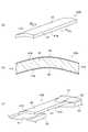
図1〜図3を参照して、第一実施形態に係る圧電アクチュエータの構成を説明する。第一実施形態は、HDD用のサスペンション10が圧電アクチュエータを含んでいる例である。図1は、第一実施形態に係るサスペンションを示す概略平面図である。図2は、図1に示されたII−II線に沿った断面構成を説明するための図である。図3(a)は図1に示された圧電素子の斜視図であり、図3(b)は図3(a)のIIIb−IIIb線に沿った断面図であり、図3(c)は図1に示された圧電素子の固定構造を説明するための図である。
[First embodiment]
With reference to FIGS. 1-3, the structure of the piezoelectric actuator which concerns on 1st embodiment is demonstrated. The first embodiment is an example in which theHDD suspension 10 includes a piezoelectric actuator. FIG. 1 is a schematic plan view showing a suspension according to the first embodiment. FIG. 2 is a view for explaining a cross-sectional configuration along the line II-II shown in FIG. 3A is a perspective view of the piezoelectric element shown in FIG. 1, FIG. 3B is a cross-sectional view taken along line IIIb-IIIb in FIG. 3A, and FIG. It is a figure for demonstrating the fixation structure of the piezoelectric element shown by FIG.

図1に示されたデュアル・アクチュエータ方式のサスペンション10は、ロードビーム11と、マイクロアクチュエータ部12と、ベースプレート13と、ヒンジ部材14と、を備えている。  The dualactuator type suspension 10 shown in FIG. 1 includes aload beam 11, amicroactuator unit 12, abase plate 13, and ahinge member 14.

ロードビーム11は、ばね性を有する金属板からなる。ロードビーム11の厚さは、たとえば100μm程度である。ロードビーム11の先端部には、フレキシャ15が取付けられている。フレキシャ15は、ロードビーム11よりもさらに薄い金属製の薄板ばねからなる。フレキシャ15の前端部に、磁気ヘッドを構成するスライダ16が配置されている。  Theload beam 11 is made of a metal plate having a spring property. The thickness of theload beam 11 is, for example, about 100 μm. Aflexure 15 is attached to the tip of theload beam 11. Theflexure 15 is made of a thin metal spring that is thinner than theload beam 11. Aslider 16 constituting a magnetic head is disposed at the front end of theflexure 15.

ベースプレート13の基部20に、円形のボス孔21が形成されている。ベースプレート13の基部20と前端部22との間には、後述する圧電素子40Aを収容可能な大きさの一対の開口部23が形成されている。一対の開口部23の間に、ベースプレート13の前後方向(サスペンション10の長手方向)に延びる帯状の連結部24が設けられている。連結部24は、ベースプレート13の幅方向(サスペンション10の長手方向と交差する方向)への所定範囲の撓みが許容されるように構成されている。  Acircular boss hole 21 is formed in thebase portion 20 of thebase plate 13. Between thebase portion 20 and thefront end portion 22 of thebase plate 13, a pair ofopenings 23 having a size capable of accommodating apiezoelectric element 40A described later is formed. Between the pair ofopenings 23, a band-shaped connectingportion 24 extending in the front-rear direction of the base plate 13 (longitudinal direction of the suspension 10) is provided. The connectingportion 24 is configured to allow a predetermined range of bending in the width direction of the base plate 13 (direction intersecting the longitudinal direction of the suspension 10).

ベースプレート13の基部20は、図示しないボイスコイルモータによって駆動されるアクチュエータアームの先端部に固定されている。これにより、ベースプレート13は、ボイスコイルモータによって旋回駆動される。ベースプレート13は、ステンレス鋼などの金属板からなる。ベースプレート13の厚さは、たとえば200μm程度である。本実施形態の場合、ベースプレート13とヒンジ部材14とによって、アクチュエータベース25が構成されている。  Thebase 20 of thebase plate 13 is fixed to the tip of an actuator arm that is driven by a voice coil motor (not shown). Thereby, thebase plate 13 is pivotally driven by the voice coil motor. Thebase plate 13 is made of a metal plate such as stainless steel. The thickness of thebase plate 13 is, for example, about 200 μm. In the case of the present embodiment, theactuator base 25 is configured by thebase plate 13 and thehinge member 14.

ヒンジ部材14は、基部30と、ブリッジ部31と、中間部32と、一対のヒンジ部33と、先端部34と、を有している。基部30は、ベースプレート13の基部20に重ねて固定されている。ブリッジ部31は、帯状を呈し、ベースプレート13の連結部24と対応した位置に形成されている。中間部32は、ベースプレート13の前端部22と対応した位置に形成されている。各ヒンジ部33は、板厚方向に弾性変形可能な可撓性を有している。先端部34は、ロードビーム11に固定されている。ヒンジ部材14は、ばね性を有する金属板からなる。ヒンジ部材14の厚さは、たとえば50μm程度である。  Thehinge member 14 includes abase portion 30, abridge portion 31, anintermediate portion 32, a pair ofhinge portions 33, and adistal end portion 34. Thebase 30 is overlapped and fixed on thebase 20 of thebase plate 13. Thebridge portion 31 has a belt shape and is formed at a position corresponding to the connectingportion 24 of thebase plate 13. Theintermediate portion 32 is formed at a position corresponding to thefront end portion 22 of thebase plate 13. Eachhinge part 33 has the flexibility which can be elastically deformed in a plate | board thickness direction. Thedistal end portion 34 is fixed to theload beam 11. Thehinge member 14 is made of a metal plate having a spring property. The thickness of thehinge member 14 is, for example, about 50 μm.

マイクロアクチュエータ部12には、一対の圧電素子40Aが配置されている。各圧電素子40Aは、いわゆる積層型圧電素子である。各圧電素子40Aは、図2及び図3にも示されるように、圧電体41と、第一外部電極42と、第二外部電極43と、を備えている。  A pair of piezoelectric elements 40 </ b> A is disposed in themicroactuator unit 12. Eachpiezoelectric element 40A is a so-called multilayer piezoelectric element. Each piezoelectric element 40 </ b> A includes apiezoelectric body 41, a firstexternal electrode 42, and a secondexternal electrode 43 as shown in FIGS. 2 and 3.

圧電体41は、平面視で長方形状を呈する板状の圧電体である。圧電体41は、圧電体41の厚さ方向で互いに対向する第一及び第二主面41a,41bと、第一及び第二主面41a,41bの長手方向(以下、単に「長手方向」という)で互いに対向し且つ長手方向に直交する幅方向(以下、単に「幅方向」という)に延びる一対の第一及び第二端面41c,41dと、長手方向に延び且つ幅方向で互いに対向する一対の第一及び第二側面41e,41fと、を有している。  Thepiezoelectric body 41 is a plate-like piezoelectric body that has a rectangular shape in plan view. Thepiezoelectric body 41 includes first and secondmain surfaces 41a and 41b facing each other in the thickness direction of thepiezoelectric body 41, and a longitudinal direction of the first and secondmain surfaces 41a and 41b (hereinafter simply referred to as “longitudinal direction”). ) And a pair of first and second end faces 41c and 41d extending in the width direction (hereinafter simply referred to as “width direction”) orthogonal to the longitudinal direction, and a pair extending in the longitudinal direction and facing each other in the width direction. First and second side faces 41e, 41f.

圧電体41は、長手方向に直交する断面において、第二主面41b側が凸となるように湾曲し、アーチ状をなしている。圧電体41は、長手方向の全ての位置において、長手方向に直交する断面における形状が略同等である。圧電体41は、圧電体41を幅方向に二等分する仮想的な面である中央面(以下、単に「中央面」という)に対して面対称をなしている。圧電体41の外形寸法は、たとえば、長さ(第一及び第二端面41c,41d間の距離)1.0mm、幅(第一及び第二側面11e,11f間の距離)0.3mm、厚さ(第一及び第二主面41a,41b間の距離)0.05mmである。長手方向に直交する断面における圧電体41の湾曲の曲率半径は、たとえば、0.1mm〜0.2mm程度である。  In the cross section orthogonal to the longitudinal direction, thepiezoelectric body 41 is curved so that the secondmain surface 41b side is convex, and has an arch shape. Thepiezoelectric body 41 has substantially the same shape in the cross section orthogonal to the longitudinal direction at all positions in the longitudinal direction. Thepiezoelectric body 41 is plane-symmetric with respect to a central plane (hereinafter simply referred to as “central plane”) that is a virtual plane that bisects thepiezoelectric body 41 in the width direction. The external dimensions of thepiezoelectric body 41 are, for example, a length (distance between the first and second end faces 41c and 41d) of 1.0 mm, a width (distance between the first and second side faces 11e and 11f) of 0.3 mm, and a thickness. The distance (the distance between the first and secondmain surfaces 41a and 41b) is 0.05 mm. The curvature radius of the curvature of thepiezoelectric body 41 in the cross section orthogonal to the longitudinal direction is, for example, about 0.1 mm to 0.2 mm.

圧電体41は、圧電セラミックからなる。圧電セラミックとしては、PZT[Pb(Zr,Ti)O]、PT[PbTiO]、PLZT[(Pb,La)(Zr,Ti)O]、又はチタン酸バリウム[BaTiO]などが挙げられる。圧電体41は、たとえば、PZTなどの圧電セラミック材料で構成されている。Thepiezoelectric body 41 is made of a piezoelectric ceramic. Examples of the piezoelectric ceramic include PZT [Pb (Zr, Ti) O3 ], PT [PbTiO3 ], PLZT [(Pb, La) (Zr, Ti) O3 ], or barium titanate [BaTiO3 ]. It is done. Thepiezoelectric body 41 is made of, for example, a piezoelectric ceramic material such as PZT.

第一外部電極42は、第一主面41aに沿って第一主面41aに配置されている。第一外部電極42は、第一主面41aの全部を覆うように配置されている。第一外部電極42の厚さは、たとえば200〜500nm程度に設定される。  The firstexternal electrode 42 is disposed on the firstmain surface 41a along the firstmain surface 41a. The firstexternal electrode 42 is disposed so as to cover the entire firstmain surface 41a. The thickness of the firstexternal electrode 42 is set to, for example, about 200 to 500 nm.

第二外部電極43は、第二主面41bに沿って第二主面41bに配置されている。第二外部電極43は、第二主面41bの全部を覆うように配置されている。第二外部電極43の厚さは、第一外部電極42の厚さと同じに設定される。すなわち、第二外部電極43の厚さは、たとえば200〜500nm程度に設定される。  The secondexternal electrode 43 is disposed on the secondmain surface 41b along the secondmain surface 41b. The secondexternal electrode 43 is disposed so as to cover the entire secondmain surface 41b. The thickness of the secondexternal electrode 43 is set to be the same as the thickness of the firstexternal electrode 42. That is, the thickness of the secondexternal electrode 43 is set to, for example, about 200 to 500 nm.

本実施形態では、第一及び第二外部電極42,43は、Cr/Ni−Cu/Au積層構造(圧電体41側から順にCr層、Ni−Cu合金層、Au層が積層された構造)とされている。すなわち、第一及び第二外部電極42,43は、同じ積層構造を有している。第一及び第二外部電極42,43は、スパッタリング法により形成されている。第一及び第二外部電極42,43は、スパッタリング法以外の方法(たとえば、焼き付け法、電解めっき法、又は蒸着法など)により形成されていてもよい。第一及び第二外部電極42,43は、単層の同じ金属層(Cr層、Ni−Cu合金層、Au層、又はNi層など)として形成されていてもよい。  In the present embodiment, the first and secondexternal electrodes 42 and 43 have a Cr / Ni—Cu / Au laminated structure (a structure in which a Cr layer, a Ni—Cu alloy layer, and an Au layer are laminated in this order from thepiezoelectric body 41 side). It is said that. That is, the first and secondexternal electrodes 42 and 43 have the same laminated structure. The first and secondexternal electrodes 42 and 43 are formed by a sputtering method. The first and secondexternal electrodes 42 and 43 may be formed by a method other than the sputtering method (for example, a baking method, an electrolytic plating method, or a vapor deposition method). The first and secondexternal electrodes 42 and 43 may be formed as a single metal layer (such as a Cr layer, a Ni—Cu alloy layer, an Au layer, or a Ni layer).

各圧電素子40Aは、長手方向が、ベースプレート13の前後方向(サスペンション10の軸線方向)に沿うようにして、対応する開口部23に収容されている。すなわち、各圧電素子40Aは、対応する開口部23に配置されている。  Eachpiezoelectric element 40A is accommodated in thecorresponding opening 23 so that the longitudinal direction is along the front-rear direction of the base plate 13 (the axial direction of the suspension 10). That is, each piezoelectric element 40 </ b> A is disposed in thecorresponding opening 23.

各圧電素子40Aは、第一端面41c側において、ヒンジ部材14の中間部32に支持されるように、中間部32に樹脂50によって固定されている。詳細には、圧電体41の第一端面41cと、圧電体41の第一及び第二側面41e,41fの第一端面41c側の一部分と、圧電素子40A(第一外部電極42)における第一主面41a側且つ第一端面41c側の一部分と、がそれぞれ樹脂50を介して中間部32に固定されている。また、第一端面41c側において、第二外部電極43上には導電性樹脂51が形成されている。第二外部電極43は、導電性樹脂51により図示しない電気配線に接続されている。導電性樹脂51は、導電性材料(たとえば金属粒子など)を含有する樹脂である。  Eachpiezoelectric element 40A is fixed to theintermediate portion 32 with aresin 50 so as to be supported by theintermediate portion 32 of thehinge member 14 on thefirst end face 41c side. Specifically, thefirst end face 41c of thepiezoelectric body 41, the first and second side faces 41e and 41f of thepiezoelectric body 41 on thefirst end face 41c side, and the first in thepiezoelectric element 40A (first external electrode 42). A part on themain surface 41a side and thefirst end surface 41c side is fixed to theintermediate portion 32 via aresin 50, respectively. Further, aconductive resin 51 is formed on the secondexternal electrode 43 on thefirst end face 41 c side. The secondexternal electrode 43 is connected to an electrical wiring (not shown) by aconductive resin 51. Theconductive resin 51 is a resin containing a conductive material (for example, metal particles).

各圧電素子40Aは、第二端面41d側において、ヒンジ部材14の基部30に支持されるように、基部30に導電性樹脂51によって固定されている。詳細には、圧電体41の第二端面41dと、圧電体41の第一及び第二側面41e,41fの第二端面41d側の一部分と、圧電素子40A(第一外部電極42)における第一主面41a側且つ第二端面41d側の一部分と、がそれぞれ導電性樹脂51を介して基部30に固定されている。第一外部電極42は、導電性樹脂51により図示しない電気配線に接続されている。  Eachpiezoelectric element 40A is fixed to the base 30 with aconductive resin 51 so as to be supported by thebase 30 of thehinge member 14 on thesecond end face 41d side. Specifically, thesecond end face 41d of thepiezoelectric body 41, the first and second side faces 41e and 41f of thepiezoelectric body 41 on thesecond end face 41d side, and the first in thepiezoelectric element 40A (first external electrode 42). A part on themain surface 41 a side and thesecond end surface 41 d side is fixed to thebase portion 30 via theconductive resin 51. The firstexternal electrode 42 is connected to an electrical wiring (not shown) by aconductive resin 51.

圧電素子40Aは、上述したように、ヒンジ部材14の中間部32及び基部30により拘束されて支持されている。中間部32及び基部30は、圧電素子40Aを拘束して支持する支持部材として機能する。すなわち、圧電素子40Aは、第一主面41a側から圧電体41に作用する拘束力が、第二主面41b側から圧電体41に作用する拘束力より大きい状態で、支持部材(中間部32及び基部30)に拘束されて支持されている。本実施形態においては、サスペンション10が、圧電素子40Aと、支持部材(中間部32及び基部30)と、を備える圧電アクチュエータを含むこととなる。  As described above, thepiezoelectric element 40A is supported by being restrained by theintermediate portion 32 and thebase portion 30 of thehinge member 14. Theintermediate portion 32 and thebase portion 30 function as a support member that restrains and supports thepiezoelectric element 40A. That is, thepiezoelectric element 40A has a supporting member (intermediate portion 32) in a state where the restraining force acting on thepiezoelectric body 41 from the firstmain surface 41a side is larger than the restraining force acting on thepiezoelectric body 41 from the secondmain surface 41b side. And supported by the base 30). In the present embodiment, thesuspension 10 includes a piezoelectric actuator including thepiezoelectric element 40A and support members (theintermediate portion 32 and the base portion 30).

次に、上述した圧電素子40Aの製造方法について説明する。  Next, a manufacturing method of the above-describedpiezoelectric element 40A will be described.

まず、圧電セラミック粉のペーストを得て、ペーストから所定厚さのグリーンシートを作成する(シート工法)。グリーンシートに電極を印刷してもよい。また、グリーンシートを重ね合わせて積層体としてもよい。次に、グリーンシート又はその積層体を積層方向にプレス処理し、圧電体グリーンを得る。  First, a piezoelectric ceramic powder paste is obtained, and a green sheet having a predetermined thickness is prepared from the paste (sheet method). An electrode may be printed on the green sheet. Alternatively, green sheets may be stacked to form a laminate. Next, the green sheet or the laminated body is pressed in the laminating direction to obtain piezoelectric green.

プレス処理は、目的の形状にあわせて行われる。すなわち、本実施形態では、圧電体グリーンが湾曲し、長手方向に直交する断面において、圧電体グリーンにおける第二主面41bに対応する面側が凸となるようにプレス処理する。プレス処理は、たとえば、100MPa程度で行われるのが好ましい。続いて、得られた圧電体グリーンに脱バインダ処理を施した後、焼成し、圧電体基板を得る。なお、焼成後の圧電体基板の各主面に対し、研磨処理等の表面処理を行ってもよい。  The press process is performed according to the target shape. That is, in the present embodiment, the piezoelectric green is curved, and the pressing is performed so that the surface side corresponding to the secondmain surface 41b of the piezoelectric green is convex in the cross section orthogonal to the longitudinal direction. The press treatment is preferably performed at, for example, about 100 MPa. Subsequently, the obtained piezoelectric green is subjected to binder removal processing and then fired to obtain a piezoelectric substrate. A surface treatment such as a polishing treatment may be performed on each main surface of the fired piezoelectric substrate.

次に、圧電体基板の各主面上に電極膜を形成する。各電極膜は、印刷法、スパッタリング法又は蒸着法などにより形成される。以上の工程により、圧電体基板及び電極膜を備える圧電素子基板が得られる。圧電体基板は、個片化された状態の複数の圧電体41が繋がった状態であり、各電極膜は、個片化された状態の複数の第一及び第二外部電極42,43が繋がった状態であり、圧電素子基板は、個片化された状態の複数の圧電素子40Aが繋がった状態である。  Next, an electrode film is formed on each main surface of the piezoelectric substrate. Each electrode film is formed by a printing method, a sputtering method, a vapor deposition method, or the like. Through the above steps, a piezoelectric element substrate including a piezoelectric substrate and an electrode film is obtained. The piezoelectric substrate is in a state where a plurality ofpiezoelectric bodies 41 in an individualized state are connected, and each electrode film is connected in a plurality of first and secondexternal electrodes 42, 43 in an individualized state. The piezoelectric element substrate is in a state where a plurality ofpiezoelectric elements 40A in a state of being separated are connected.

次に、圧電素子基板に分極処理を行う。分極処理では、たとえば、100℃の温度下で、電界強度2kV/mmの電圧を5分間程度印加する。続いて、分極処理後の圧電素子基板を製品形状に切断する。これにより、個片化された圧電体41及び第一及び第二外部電極42,43を備える圧電素子40Aが得られる。  Next, polarization processing is performed on the piezoelectric element substrate. In the polarization treatment, for example, a voltage with an electric field strength of 2 kV / mm is applied at a temperature of 100 ° C. for about 5 minutes. Subsequently, the piezoelectric element substrate after the polarization treatment is cut into a product shape. Thereby, thepiezoelectric element 40A including thepiezoelectric body 41 and the first and secondexternal electrodes 42 and 43 which are separated into pieces is obtained.

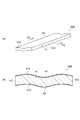
次に、図4を参照して、サスペンション10(圧電アクチュエータ)の動作について説明する。図4は、第一実施形態に係るサスペンションの動作を説明するための図である。  Next, the operation of the suspension 10 (piezoelectric actuator) will be described with reference to FIG. FIG. 4 is a view for explaining the operation of the suspension according to the first embodiment.

図4の(a)に示された圧電素子40Aでは、第一及び第二外部電極42,43に電圧が印加されておらず、第一及び第二外部電極42,43を通して圧電体41に電界が印加されていない。第一及び第二外部電極42,43に電圧が印加され、第一及び第二外部電極42,43を通して圧電体41に所定の電界が印加されることにより圧電素子40Aが駆動されると、圧電素子40Aは、図4の(b)に示されるように、駆動方向D1に伸長する。ここでは、駆動方向D1は長手方向である。すなわち、圧電素子40Aの長手方向での変位が圧電アクチュエータの駆動に利用されている。  In the piezoelectric element 40 </ b> A shown in FIG. 4A, no voltage is applied to the first and secondexternal electrodes 42 and 43, and an electric field is applied to thepiezoelectric body 41 through the first and secondexternal electrodes 42 and 43. Is not applied. When thepiezoelectric element 40A is driven by applying a voltage to the first and secondexternal electrodes 42 and 43 and applying a predetermined electric field to thepiezoelectric body 41 through the first and secondexternal electrodes 42 and 43, thepiezoelectric element 40A is driven. Theelement 40A extends in the driving direction D1 as shown in FIG. Here, the driving direction D1 is a longitudinal direction. That is, the displacement in the longitudinal direction of thepiezoelectric element 40A is used for driving the piezoelectric actuator.

圧電素子40Aは、上述したように、第一主面41a側から圧電体41に作用する拘束力が、第二主面41b側から圧電体41に作用する拘束力より大きい状態で、支持部材(中間部32及び基部30)に拘束されて支持されている。このため、圧電素子40Aは、支持部材に拘束されて支持されている状態では、圧電体41における第一主面41a側の領域は、同じく圧電体41における第二主面41b側の領域よりも変位が阻害され易い。したがって、圧電素子40Aは、第二主面41b側が湾曲外側となるように撓もうとする。しかしながら、上述したように、圧電素子40Aは、長手方向に直交する断面において湾曲している。このため、圧電素子40Aの剛性(曲げ剛性)が高まり、図4の(b)に示されるように、第二主面41b側が湾曲外側となる撓みが抑制されることとなる。  As described above, thepiezoelectric element 40A has a supporting member (with a restraining force acting on thepiezoelectric body 41 from the firstmain surface 41a side larger than a restraining force acting on thepiezoelectric body 41 from the secondmain surface 41b side). Theintermediate part 32 and the base part 30) are restrained and supported. For this reason, in a state where thepiezoelectric element 40A is restrained and supported by the support member, the region on the firstmain surface 41a side of thepiezoelectric body 41 is also more than the region on the secondmain surface 41b side of thepiezoelectric body 41. Displacement is easily disturbed. Therefore, thepiezoelectric element 40A tends to bend so that the secondmain surface 41b side is on the curved outer side. However, as described above, thepiezoelectric element 40A is curved in a cross section orthogonal to the longitudinal direction. For this reason, the rigidity (bending rigidity) of thepiezoelectric element 40A is increased, and as shown in FIG. 4B, the secondmain surface 41b side is prevented from being bent outward.

以上のことから、第一実施形態においては、圧電素子40Aの撓み変形が抑制されるので、圧電素子40Aの撓み変形に伴う圧電素子の損傷を抑制することができる。  From the above, in the first embodiment, since the bending deformation of thepiezoelectric element 40A is suppressed, damage to the piezoelectric element due to the bending deformation of thepiezoelectric element 40A can be suppressed.

以上説明したように、第一実施形態では、サスペンション10は、圧電素子40Aと、支持部材と、を備えている。圧電素子40Aは、略長方形状を呈し且つ互いに対向する第一及び第二主面41a,41bと、長手方向で互いに対向し且つ幅方向に延びる第一及び第二端面41c,41dと、を含む圧電体41と、第一主面41aに配置された第一外部電極42と、第二主面41bに配置された第二外部電極43と、を有している。圧電体41は、長手方向に直交する断面において湾曲している。支持部材は、圧電素子40Aを第一及び第二端面41c,41d側で支持している。  As described above, in the first embodiment, thesuspension 10 includes thepiezoelectric element 40A and the support member. Thepiezoelectric element 40A includes first and secondmain surfaces 41a and 41b that are substantially rectangular and face each other, and first and second end faces 41c and 41d that face each other in the longitudinal direction and extend in the width direction. Apiezoelectric body 41, a firstexternal electrode 42 disposed on the firstmain surface 41a, and a secondexternal electrode 43 disposed on the secondmain surface 41b are included. Thepiezoelectric body 41 is curved in a cross section orthogonal to the longitudinal direction. The support member supports thepiezoelectric element 40A on the first and second end faces 41c, 41d side.

圧電素子40Aは、第一及び第二端面41c,41d側で支持部材により支持されている。サスペンション10は、圧電体41が長手方向に変位することで、駆動される。圧電体41は、長手方向に直交する断面において湾曲している。このため、圧電素子40Aは、湾曲していない従来の圧電素子100よりも断面係数が大きく、駆動時の曲げに対する強度が向上する。したがって、圧電素子40Aが撓み変形することを抑え、圧電素子40Aの損傷を抑制することができる。  Thepiezoelectric element 40A is supported by a support member on the first and second end faces 41c, 41d side. Thesuspension 10 is driven when thepiezoelectric body 41 is displaced in the longitudinal direction. Thepiezoelectric body 41 is curved in a cross section orthogonal to the longitudinal direction. For this reason, thepiezoelectric element 40A has a larger section modulus than the conventionalpiezoelectric element 100 that is not curved, and the strength against bending during driving is improved. Therefore, thepiezoelectric element 40A can be prevented from being bent and deformed, and damage to thepiezoelectric element 40A can be suppressed.

上述のように、圧電素子の変位は、小型化又は薄型化されるほど向上するものの、圧電素子の剛性は、小型化又は薄型化されるほど低下する。圧電素子40Aは、圧電体41が湾曲していない従来の圧電素子100と略同等のサイズである。圧電素子40Aは、圧電体41の幅方向の長さを長くしたり、圧電体41の厚さを厚くしたりすることなく、剛性を向上させているので、従来の圧電素子100と同等の変位を維持することができる。更に、圧電素子40Aは、撓み変形することが抑えられるので、その変位を適切に支持部材に伝達することができる。  As described above, the displacement of the piezoelectric element is improved as the size is reduced or reduced, but the rigidity of the piezoelectric element is reduced as the size is reduced or reduced. Thepiezoelectric element 40A is approximately the same size as the conventionalpiezoelectric element 100 in which thepiezoelectric body 41 is not curved. Since thepiezoelectric element 40A has improved rigidity without increasing the length of thepiezoelectric body 41 in the width direction or increasing the thickness of thepiezoelectric body 41, the displacement equivalent to that of the conventionalpiezoelectric element 100 is achieved. Can be maintained. Furthermore, since thepiezoelectric element 40A is restrained from being bent and deformed, the displacement can be appropriately transmitted to the support member.

圧電素子40Aでは、圧電体41が、中央面に対して面対称をなしている。このため、圧電素子40Aは、中央面よりも第一側面41e側の部分と、中央面よりも第二側面41f側の部分とで、変位の程度に差異が生じ難い。したがって、圧電素子40Aは、その変位をより適切に支持部材に伝達することができる。  In thepiezoelectric element 40A, thepiezoelectric body 41 is plane-symmetric with respect to the center plane. For this reason, in thepiezoelectric element 40A, a difference in the degree of displacement hardly occurs between the portion closer to thefirst side surface 41e than the center surface and the portion closer to thesecond side surface 41f than the center surface. Therefore, thepiezoelectric element 40A can more appropriately transmit the displacement to the support member.

圧電素子40Aでは、圧電体41が長手方向に直交する断面において湾曲しているので、第一及び第二主面41a,41bの識別性を高めることができる。従来の圧電素子では、裏表を識別するために、たとえば識別マークを設ける必要があった。第一実施形態の圧電素子40Aによれば、このような識別マークを省略することができる。  In thepiezoelectric element 40A, since thepiezoelectric body 41 is curved in a cross section orthogonal to the longitudinal direction, the discrimination between the first and secondmain surfaces 41a and 41b can be improved. In the conventional piezoelectric element, it is necessary to provide, for example, an identification mark in order to identify the front and back. According to thepiezoelectric element 40A of the first embodiment, such an identification mark can be omitted.

圧電素子40Aが撓み変形した場合、圧電素子40Aが支持部材から剥離し易くなる。第一実施形態では、圧電素子40Aの撓み変形が抑制されるので、このような剥離の発生を抑制することができる。  When thepiezoelectric element 40A is bent and deformed, thepiezoelectric element 40A is easily peeled from the support member. In the first embodiment, since bending deformation of thepiezoelectric element 40A is suppressed, occurrence of such peeling can be suppressed.

圧電素子40Aは、たとえば厚さ0.2mm以下としてもよい。圧電素子40Aは、厚さが薄くなればなるほど剛性が低下し、撓み易くなる。第一実施形態によれば、圧電素子40Aの厚さが0.2mm以下の場合でも、圧電素子40Aの撓み変形を抑制することができる。  For example, thepiezoelectric element 40A may have a thickness of 0.2 mm or less. As the thickness of thepiezoelectric element 40A is reduced, the rigidity is lowered and thepiezoelectric element 40A is easily bent. According to the first embodiment, even when the thickness of thepiezoelectric element 40A is 0.2 mm or less, the bending deformation of thepiezoelectric element 40A can be suppressed.

続いて、図5を参照して、第一実施形態の変形例に係る圧電素子について説明する。図5(a)は第一実施形態の変形例に係る圧電素子の斜視図であり、図5(b)は図5(a)のVb−Vb線に沿った断面図である。  Next, a piezoelectric element according to a modification of the first embodiment will be described with reference to FIG. Fig.5 (a) is a perspective view of the piezoelectric element which concerns on the modification of 1st embodiment, FIG.5 (b) is sectional drawing along the Vb-Vb line | wire of Fig.5 (a).

図5に示されるように、第一実施形態の変形例に係る圧電素子40Bは、圧電体41の湾曲の形状の点で圧電素子40Aと相違し、その他の点で一致している。圧電素子40Bでは、圧電体41は、長手方向に直交する断面において、波型に湾曲している。圧電体41は、幅方向の中央において第二主面41b側が凹となり、幅方向の両端部において第二主面41b側が凸となるように湾曲している。圧電体41は、長手方向の全ての位置において、長手方向に直交する断面における形状が略同等である。圧電体41は、中央面に対して面対称をなしている。長手方向に直交する断面における圧電体41の湾曲の曲率半径は、たとえば、圧電体41の幅方向の長さの1/4程度である。  As shown in FIG. 5, the piezoelectric element 40 </ b> B according to the modification of the first embodiment is different from the piezoelectric element 40 </ b> A in terms of the curved shape of thepiezoelectric body 41, and is identical in other points. In thepiezoelectric element 40B, thepiezoelectric body 41 is curved in a wave shape in a cross section orthogonal to the longitudinal direction. Thepiezoelectric body 41 is curved so that the secondmain surface 41b side is concave at the center in the width direction and the secondmain surface 41b side is convex at both ends in the width direction. Thepiezoelectric body 41 has substantially the same shape in the cross section orthogonal to the longitudinal direction at all positions in the longitudinal direction. Thepiezoelectric body 41 is plane-symmetric with respect to the center plane. The curvature radius of the curvature of thepiezoelectric body 41 in the cross section orthogonal to the longitudinal direction is, for example, about ¼ of the length of thepiezoelectric body 41 in the width direction.

このように圧電素子40Bにおいても、圧電体41は、長手方向に直交する断面において湾曲している。このため、圧電素子40Bは、湾曲していない従来の圧電素子100よりも断面係数が大きく、駆動時の曲げに対する強度が向上する。したがって、圧電素子40Bが撓み変形することを抑え、圧電素子40Bの損傷を抑制することができる。  Thus, also in thepiezoelectric element 40B, thepiezoelectric body 41 is curved in a cross section orthogonal to the longitudinal direction. For this reason, thepiezoelectric element 40B has a larger section modulus than the conventionalpiezoelectric element 100 that is not curved, and the strength against bending during driving is improved. Therefore, thepiezoelectric element 40B can be prevented from being bent and deformed, and damage to thepiezoelectric element 40B can be suppressed.

[第二実施形態]
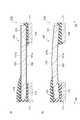
図6を参照して、第二実施形態に係る圧電アクチュエータの構成を説明する。図6(a)は第二実施形態に係る圧電素子の斜視図であり、(b)は図6(a)のVIb−VIb線に沿った断面図であり、(c)は図6(a)に示された圧電素子の固定構造について説明するための図である。
[Second Embodiment]
The configuration of the piezoelectric actuator according to the second embodiment will be described with reference to FIG. 6A is a perspective view of the piezoelectric element according to the second embodiment, FIG. 6B is a cross-sectional view taken along line VIb-VIb in FIG. 6A, and FIG. It is a figure for demonstrating the fixing structure of the piezoelectric element shown by FIG.

図6に示されるように、第二実施形態に係る圧電アクチュエータは、圧電素子40Cにおける圧電体41の形状の点で第一実施形態に係る圧電アクチュエータと相違し、その他の点で一致している。圧電体41は、第二主面41bに、長手方向に延びる一対の突条部44a,44bが設けられている。  As shown in FIG. 6, the piezoelectric actuator according to the second embodiment is different from the piezoelectric actuator according to the first embodiment in the shape of thepiezoelectric body 41 in thepiezoelectric element 40C, and is identical in other points. . Thepiezoelectric body 41 is provided with a pair ofprotrusions 44a and 44b extending in the longitudinal direction on the secondmain surface 41b.

突条部44aは、第二主面41bにおいて、第一側面41eに沿って長手方向に延びている。突条部44bは、第二主面41bにおいて、第二側面41fに沿って長手方向に延びている。一対の突条部44a,44bは、長手方向に直交する断面における形状が矩形状である。圧電体41は、中央面に対して面対称をなしている。一対の突条部44a,44bは、たとえば、幅(幅方向の長さ)が圧電体41の幅(幅方向の長さ)の1/7であり、高さ(厚さ方向の長さ)が圧電体41の高さ(厚さ方向の長さ)の1/3である。一対の突条部44a,44bは、第一端面41cから第二端面41dまで延びている。一対の突条部44a,44bは、長手方向の全ての位置において、長手方向に直交する断面における形状が略同等である。すなわち、圧電体41は、長手方向の全ての位置において、長手方向に直交する断面における形状が略同等である。  Theprotrusion 44a extends in the longitudinal direction along thefirst side surface 41e on the secondmain surface 41b. Theprotrusion 44b extends in the longitudinal direction along thesecond side surface 41f on the secondmain surface 41b. The pair ofprotrusions 44a and 44b has a rectangular shape in a cross section orthogonal to the longitudinal direction. Thepiezoelectric body 41 is plane-symmetric with respect to the center plane. The pair ofprotrusions 44a and 44b has, for example, a width (length in the width direction) that is 1/7 of a width (length in the width direction) of thepiezoelectric body 41, and a height (length in the thickness direction). Is 1/3 of the height (length in the thickness direction) of thepiezoelectric body 41. The pair ofprotrusions 44a and 44b extends from thefirst end surface 41c to thesecond end surface 41d. The pair ofprotrusions 44a and 44b have substantially the same shape in the cross section perpendicular to the longitudinal direction at all positions in the longitudinal direction. That is, thepiezoelectric body 41 has substantially the same shape in the cross section orthogonal to the longitudinal direction at all positions in the longitudinal direction.

圧電素子40Cの製造方法は、グリーンシート又はその積層体を作成する工程において、一対の突条部44a,44bに対応する部分に小さなグリーンシートを積層させる点で、圧電素子40Aの製造方法と相違し、その他の点で一致している。  The manufacturing method of thepiezoelectric element 40C is different from the manufacturing method of thepiezoelectric element 40A in that a small green sheet is stacked on portions corresponding to the pair ofprotrusions 44a and 44b in the step of forming a green sheet or a laminate thereof. And other points are in agreement.

以上説明したように、第二実施形態では、圧電素子40Cの圧電体41は、第二主面41bに、長手方向に延びる一対の突条部44a,44bが設けられている。このため、圧電素子40Cは、突条部が設けられていない従来の圧電素子100よりも断面係数が大きく、駆動時の曲げに対する強度が向上する。したがって、圧電素子40Cが撓み変形することを抑え、圧電素子40Cの損傷を抑制することができる。  As described above, in the second embodiment, thepiezoelectric body 41 of thepiezoelectric element 40C is provided with the pair ofprotrusions 44a and 44b extending in the longitudinal direction on the secondmain surface 41b. For this reason, thepiezoelectric element 40C has a larger section modulus than the conventionalpiezoelectric element 100 in which no protrusion is provided, and the strength against bending during driving is improved. Therefore, thepiezoelectric element 40C can be prevented from being bent and deformed, and damage to thepiezoelectric element 40C can be suppressed.

圧電素子40Cは、一対の突条部44a,44bが圧電体41の一部分にしか設けられていないため、従来の圧電素子100と体積が略同等である。したがって、圧電素子40Cにおいても、従来の圧電素子100よりも剛性を向上させながら、従来の圧電素子100と同等の変位を維持することができる。  The piezoelectric element 40 </ b> C has a pair ofprotrusions 44 a and 44 b that are provided only on a part of thepiezoelectric body 41, and thus has a volume substantially the same as that of the conventionalpiezoelectric element 100. Therefore, the piezoelectric element 40 </ b> C can maintain the same displacement as that of the conventionalpiezoelectric element 100 while improving the rigidity compared to the conventionalpiezoelectric element 100.

圧電素子40Cでは、圧電体41は第二主面41bに一対の突条部44a,44bが設けられているので、第一及び第二主面41a,41bの識別性を高めることができる。したがって、第二実施形態の圧電素子40Cによれば、第一及び第二主面41a,41bを識別するための識別マークを省略することができる。  In thepiezoelectric element 40C, since thepiezoelectric body 41 is provided with the pair ofprotrusions 44a and 44b on the secondmain surface 41b, the discrimination between the first and secondmain surfaces 41a and 41b can be improved. Therefore, according to thepiezoelectric element 40C of the second embodiment, identification marks for identifying the first and secondmain surfaces 41a and 41b can be omitted.

続いて、図7を参照して、第二実施形態の変形例に係る圧電素子について説明する。図7(a)は第二実施形態の変形例に係る圧電素子の斜視図であり、図7(b)は図7(a)のVIIb−VIIb線に沿った断面図である。  Next, a piezoelectric element according to a modification of the second embodiment will be described with reference to FIG. Fig.7 (a) is a perspective view of the piezoelectric element which concerns on the modification of 2nd embodiment, FIG.7 (b) is sectional drawing along the VIIb-VIIb line | wire of Fig.7 (a).

図7に示されるように、第二実施形態の変形例に係る圧電素子40Dは、圧電体41の第二主面41bに一対の突条部44a,44bの代わりに、突条部44cが設けられている点で圧電素子40Cと相違し、その他の点で一致している。  As shown in FIG. 7, the piezoelectric element 40 </ b> D according to the modification of the second embodiment is provided with aprotrusion 44 c on the secondmain surface 41 b of thepiezoelectric body 41 instead of the pair ofprotrusions 44 a and 44 b. This is different from thepiezoelectric element 40C in that the other points are the same.

突条部44cは、第二主面41bにおいて、幅方向の中央部分に設けられ、長手方向に延びている。突条部44cは、長手方向に直交する断面における形状が矩形状である。圧電体41は、中央面に対して面対称をなしている。突条部44cは、たとえば、幅(幅方向の長さ)が圧電体41の幅(幅方向の長さ)の1/5であり、高さ(厚さ方向の長さ)が圧電体41の高さ(厚さ方向の長さ)の1/3である。突条部44cは、第一端面41cから第二端面41dまで延びている。突条部44cは、長手方向の全ての位置において、長手方向に直交する断面における形状が略同等である。すなわち、圧電体41は、長手方向の全ての位置において、長手方向に直交する断面における形状が略同等である。  Theprotrusion 44c is provided in the center portion in the width direction on the secondmain surface 41b and extends in the longitudinal direction. Theprotrusion 44c has a rectangular shape in a cross section orthogonal to the longitudinal direction. Thepiezoelectric body 41 is plane-symmetric with respect to the center plane. For example, theprotrusion 44c has a width (length in the width direction) that is 1/5 of a width (length in the width direction) of thepiezoelectric body 41 and a height (length in the thickness direction) of thepiezoelectric body 41. 1/3 of the height (length in the thickness direction). The protrudingportion 44c extends from thefirst end surface 41c to thesecond end surface 41d. Theprotrusions 44c have substantially the same shape in the cross section perpendicular to the longitudinal direction at all positions in the longitudinal direction. That is, thepiezoelectric body 41 has substantially the same shape in the cross section orthogonal to the longitudinal direction at all positions in the longitudinal direction.

このように圧電素子40Dにおいても、圧電体41は、第二主面41bに、長手方向に延びる突条部44cが設けられている。このため、圧電素子40Dは、突条部が設けられていない従来の圧電素子100よりも断面係数が大きく、駆動時の曲げに対する強度が向上する。したがって、圧電素子40Dが撓み変形することを抑え、圧電素子40Dの損傷を抑制することができる。  Thus, also in thepiezoelectric element 40D, thepiezoelectric body 41 is provided with theprotrusion 44c extending in the longitudinal direction on the secondmain surface 41b. For this reason, thepiezoelectric element 40D has a larger section modulus than the conventionalpiezoelectric element 100 in which no protrusion is provided, and the strength against bending during driving is improved. Therefore, thepiezoelectric element 40D can be prevented from being bent and deformed, and damage to thepiezoelectric element 40D can be suppressed.

以上、本発明の実施形態について説明したが、本発明は上記実施形態に限定されるものではなく、各請求項に記載した要旨を変更しない範囲で変形し、又は他のものに適用したものであってもよい。  As mentioned above, although embodiment of this invention was described, this invention is not limited to the said embodiment, It deform | transforms in the range which does not change the summary described in each claim, or applied to another thing. There may be.

圧電素子40Aでは、圧電体41は長手方向に直交する断面において、第二主面41b側が凸となるように湾曲しているが、圧電体41は長手方向に直交する断面において湾曲していればよく、たとえば、第一主面41a側が凸となるように湾曲していてもよい。また、圧電素子40Bでは、圧電体41は幅方向の中央において第二主面41b側が凹となり、幅方向の両端部において第二主面41b側が凸となるように湾曲しているが、幅方向の中央において第一主面41a側が凹となり、幅方向の両端部において第一主面41a側が凸となるように湾曲していてもよい。  In thepiezoelectric element 40A, thepiezoelectric body 41 is curved so that the secondmain surface 41b side is convex in the cross section orthogonal to the longitudinal direction, but thepiezoelectric body 41 is curved in the cross section orthogonal to the longitudinal direction. For example, you may curve so that the 1stmain surface 41a side may become convex. In thepiezoelectric element 40B, thepiezoelectric body 41 is curved so that the secondmain surface 41b side is concave at the center in the width direction and the secondmain surface 41b side is convex at both ends in the width direction. It may be curved so that the firstmain surface 41a side is concave at the center, and the firstmain surface 41a side is convex at both ends in the width direction.

圧電素子40Cでは、圧電体41は第二主面41bに一対の突条部44a,44bが設けられているが、圧電体41は第一及び第二主面41a,41bの少なくともいずれか一方に、長手方向に延びる突条部が設けられていればよく、突条部の数、突条部の長手方向に直交する断面における形状、及び突条部の配置等は限定されない。したがって、たとえば、第一主面41aに一対の突条部44a,44bが設けられていてもよい。また、第一及び第二主面41a,41bの両方に一対の突条部44a,44bが設けられていてもよい。  In thepiezoelectric element 40C, thepiezoelectric body 41 is provided with a pair ofprotrusions 44a and 44b on the secondmain surface 41b, but thepiezoelectric body 41 is provided on at least one of the first and secondmain surfaces 41a and 41b. The protrusions extending in the longitudinal direction may be provided, and the number of protrusions, the shape of the protrusion in the cross section orthogonal to the longitudinal direction, the arrangement of the protrusions, and the like are not limited. Therefore, for example, a pair ofprotrusions 44a and 44b may be provided on the firstmain surface 41a. Moreover, a pair ofprotrusion part 44a, 44b may be provided in both the 1st and 2ndmain surface 41a, 41b.

同様に、圧電素子40Dでは、第一主面41aに突条部44cが設けられていてもよい。また、第一及び第二主面41a,41bの両方に突条部44cが設けられていてもよい。  Similarly, in thepiezoelectric element 40D, aprotrusion 44c may be provided on the firstmain surface 41a. Moreover, theprotrusion 44c may be provided in both the 1st and 2ndmain surfaces 41a and 41b.

圧電素子40A〜40Dでは、圧電体41は、長手方向の全ての位置において、長手方向に直交する断面における形状が略同等であるが、長手方向の位置により、長手方向に直交する断面における形状が異なっていてもよい。圧電体41は、長手方向の中央部分において、最も撓み変形し易くなる。したがって、たとえば、圧電素子40A,40Bでは、圧電体41は、長手方向の中央部分において湾曲し、第一及び第二端面41c,41d側の両端部分において湾曲しない形状としてもよい。また、圧電素子40Cでは、圧電体41は、長手方向の中央部分において一対の突条部44a,44bが設けられ、第一及び第二端面41c,41d側の両端部分において一対の突条部44a,44bが設けられない形状としてもよい。また、圧電素子40Dでは、圧電体41は、長手方向の中央部分において突条部44cが設けられ、第一及び第二端面41c,41d側の両端部分において突条部44cが設けられていない形状としてもよい。  In the piezoelectric elements 40 </ b> A to 40 </ b> D, thepiezoelectric body 41 has substantially the same shape in the cross section perpendicular to the longitudinal direction at all positions in the longitudinal direction, but the shape in the cross section perpendicular to the longitudinal direction depends on the position in the longitudinal direction. May be different. Thepiezoelectric body 41 is most easily bent and deformed in the central portion in the longitudinal direction. Therefore, for example, in thepiezoelectric elements 40A and 40B, thepiezoelectric body 41 may be curved at the center portion in the longitudinal direction and not curved at both end portions on the first and second end faces 41c and 41d side. Further, in thepiezoelectric element 40C, thepiezoelectric body 41 is provided with a pair ofprotrusions 44a and 44b at the central portion in the longitudinal direction, and a pair ofprotrusions 44a at both end portions on the first and second end faces 41c and 41d side. , 44b may not be provided. Further, in thepiezoelectric element 40D, thepiezoelectric body 41 has a shape in which theprotrusion 44c is provided in the central portion in the longitudinal direction and theprotrusion 44c is not provided in both end portions on the first and second end faces 41c, 41d side. It is good.

圧電素子40A〜40Dでは、ヒンジ部材14の中間部32及び基部30が支持部材として機能しているが、これに加えて、たとえばベースプレート13の前端部22、基部20、及び連結部24が支持部材として機能してもよい。  In thepiezoelectric elements 40A to 40D, theintermediate portion 32 and thebase portion 30 of thehinge member 14 function as support members. In addition, for example, thefront end portion 22, thebase portion 20, and the connectingportion 24 of thebase plate 13 are support members. May function as

本発明は、HDD用のサスペンション10のマイクロアクチュエータ部12以外の圧電アクチュエータに用いることができる。  The present invention can be used for piezoelectric actuators other than themicroactuator portion 12 of theHDD suspension 10.

10…サスペンション、11…ロードビーム、12…マイクロアクチュエータ部、13…ベースプレート、14…ヒンジ部材、25…アクチュエータベース、30…基部、32…中間部、40A〜40D…圧電素子、41…圧電体、41a…第一主面、41b…第二主面、41c…第一端面、41d…第二端面、44a〜44c…突条部。
DESCRIPTION OFSYMBOLS 10 ... Suspension, 11 ... Load beam, 12 ... Micro actuator part, 13 ... Base plate, 14 ... Hinge member, 25 ... Actuator base, 30 ... Base part, 32 ... Middle part, 40A-40D ... Piezoelectric element, 41 ... Piezoelectric body, 41a ... 1st main surface, 41b ... 2nd main surface, 41c ... 1st end surface, 41d ... 2nd end surface, 44a-44c ... Projection part.

Claims (2)

Translated fromJapanese
圧電素子と、前記圧電素子を支持する支持部材と、を備える圧電アクチュエータであって、
前記圧電素子は、
略長方形状を呈し且つ互いに対向する第一及び第二主面と、前記第一及び第二主面の長手方向で互いに対向し且つ前記長手方向に直交する幅方向に延びる第一及び第二端面と、を含む圧電体と、
前記第一主面に配置された第一外部電極と、
前記第二主面に配置された第二外部電極と、を有し、
前記圧電体は、前記長手方向に直交する断面において湾曲しており、
前記支持部材は、前記圧電素子を前記第一及び第二端面側で支持している、
圧電アクチュエータ。
A piezoelectric actuator comprising a piezoelectric element and a support member that supports the piezoelectric element,
The piezoelectric element is
First and second main faces that are substantially rectangular and face each other, and first and second end faces that face each other in the longitudinal direction of the first and second principal faces and extend in the width direction perpendicular to the longitudinal direction And a piezoelectric body including
A first external electrode disposed on the first main surface;
A second external electrode disposed on the second main surface,
The piezoelectric body is curved in a cross section perpendicular to the longitudinal direction,
The support member supports the piezoelectric element on the first and second end face sides,
Piezoelectric actuator.
圧電素子と、前記圧電素子を支持する支持部材と、を備える圧電アクチュエータであって、
前記圧電素子は、
略長方形状を呈し且つ互いに対向する第一及び第二主面と、前記第一及び第二主面の長手方向で互いに対向し且つ前記長手方向に直交する幅方向に延びる第一及び第二端面と、を含む圧電体と、
前記第一主面に配置された第一外部電極と、
前記第二主面に配置された第二外部電極と、を有し、
前記圧電体は、前記第一及び第二主面の少なくともいずれか一方に、前記長手方向に延びる突条部が設けられており、
前記支持部材は、前記圧電素子を前記第一及び第二端面側で支持している、
圧電アクチュエータ。


A piezoelectric actuator comprising a piezoelectric element and a support member that supports the piezoelectric element,
The piezoelectric element is
First and second main faces that are substantially rectangular and face each other, and first and second end faces that face each other in the longitudinal direction of the first and second principal faces and extend in the width direction perpendicular to the longitudinal direction And a piezoelectric body including
A first external electrode disposed on the first main surface;
A second external electrode disposed on the second main surface,
The piezoelectric body is provided with a protrusion extending in the longitudinal direction on at least one of the first and second main surfaces,
The support member supports the piezoelectric element on the first and second end face sides,
Piezoelectric actuator.


JP2014259914A2014-12-242014-12-24 Piezoelectric actuatorActiveJP6439438B6 (en)

Priority Applications (1)

Application NumberPriority DateFiling DateTitle
JP2014259914AJP6439438B6 (en)2014-12-242014-12-24 Piezoelectric actuator

Applications Claiming Priority (1)

Application NumberPriority DateFiling DateTitle
JP2014259914AJP6439438B6 (en)2014-12-242014-12-24 Piezoelectric actuator

Publications (3)

Publication NumberPublication Date
JP2016122674Atrue JP2016122674A (en)2016-07-07
JP6439438B2 JP6439438B2 (en)2018-12-19
JP6439438B6 JP6439438B6 (en)2019-01-30

Family

ID=56327485

Family Applications (1)

Application NumberTitlePriority DateFiling Date
JP2014259914AActiveJP6439438B6 (en)2014-12-242014-12-24 Piezoelectric actuator

Country Status (1)

CountryLink
JP (1)JP6439438B6 (en)

Citations (3)

* Cited by examiner, † Cited by third party
Publication numberPriority datePublication dateAssigneeTitle
JP2003506858A (en)*1999-07-202003-02-18エスアールアイ インターナショナル Electroactive polymer
JP2005522162A (en)*2002-03-182005-07-21エスアールアイ インターナショナル Electroactive polymer devices that move fluids
JP2013538446A (en)*2010-07-262013-10-10富士フイルム株式会社 Formation of devices with curved piezoelectric films

Patent Citations (3)

* Cited by examiner, † Cited by third party
Publication numberPriority datePublication dateAssigneeTitle
JP2003506858A (en)*1999-07-202003-02-18エスアールアイ インターナショナル Electroactive polymer
JP2005522162A (en)*2002-03-182005-07-21エスアールアイ インターナショナル Electroactive polymer devices that move fluids
JP2013538446A (en)*2010-07-262013-10-10富士フイルム株式会社 Formation of devices with curved piezoelectric films

Also Published As

Publication numberPublication date
JP6439438B2 (en)2018-12-19
JP6439438B6 (en)2019-01-30

Similar Documents

PublicationPublication DateTitle
JP6690141B2 (en) Piezoelectric element and piezoelectric actuator
JP2010278288A (en) Piezoelectric element with electrode and head suspension
CN110098317B (en)Laminated piezoelectric ceramic component and piezoelectric device
JP6536269B2 (en) Piezoelectric element and piezoelectric actuator
JP5877195B2 (en) Piezoelectric device and method for producing green molded body which is molded body before firing
JP5200459B2 (en) Actuator
JP5673752B2 (en) Piezoelectric actuator
JP6361640B2 (en) Piezoelectric element and piezoelectric actuator
JP5429140B2 (en) Piezoelectric actuator
JP2010161286A (en)Laminated piezoelectric element and method of manufacturing the same
JP6428133B2 (en) Piezoelectric actuator
JP6439438B6 (en) Piezoelectric actuator
JP5633599B2 (en) Piezoelectric element
US8330330B2 (en)Piezoelectric actuator and method of manufacturing the same
US11309481B2 (en)Multi-layer piezoelectric ceramic component-mounted piezoelectric device
CN113066924B (en)Thin film piezoelectric sensing element and manufacturing method thereof, sensing device and terminal
JP6439422B6 (en) Piezoelectric actuator
JP6459731B2 (en) Piezoelectric element, piezoelectric actuator, and method of manufacturing piezoelectric element
JP5713133B1 (en) Piezoelectric actuator
JP6217688B2 (en) Piezoelectric element
JP5589395B2 (en) Piezoelectric actuator
JP6237693B2 (en) Piezoelectric element
WO2016076361A1 (en)Piezoelectric device

Legal Events

DateCodeTitleDescription
A621Written request for application examination

Free format text:JAPANESE INTERMEDIATE CODE: A621

Effective date:20170824

A131Notification of reasons for refusal

Free format text:JAPANESE INTERMEDIATE CODE: A131

Effective date:20180424

A977Report on retrieval

Free format text:JAPANESE INTERMEDIATE CODE: A971007

Effective date:20180427

A521Request for written amendment filed

Free format text:JAPANESE INTERMEDIATE CODE: A523

Effective date:20180611

TRDDDecision of grant or rejection written
A01Written decision to grant a patent or to grant a registration (utility model)

Free format text:JAPANESE INTERMEDIATE CODE: A01

Effective date:20181023

A61First payment of annual fees (during grant procedure)

Free format text:JAPANESE INTERMEDIATE CODE: A61

Effective date:20181105

R150Certificate of patent or registration of utility model

Ref document number:6439438

Country of ref document:JP

Free format text:JAPANESE INTERMEDIATE CODE: R150

R250Receipt of annual fees

Free format text:JAPANESE INTERMEDIATE CODE: R250


[8]ページ先頭

©2009-2025 Movatter.jp