JP2016119794A - Drive device - Google Patents
Drive deviceDownload PDFInfo
- Publication number
- JP2016119794A JP2016119794AJP2014258883AJP2014258883AJP2016119794AJP 2016119794 AJP2016119794 AJP 2016119794AJP 2014258883 AJP2014258883 AJP 2014258883AJP 2014258883 AJP2014258883 AJP 2014258883AJP 2016119794 AJP2016119794 AJP 2016119794A
- Authority
- JP
- Japan
- Prior art keywords
- substrate
- frame member
- locking member
- drive device
- boss
- Prior art date
- Legal status (The legal status is an assumption and is not a legal conclusion. Google has not performed a legal analysis and makes no representation as to the accuracy of the status listed.)
- Granted
Links
- 239000000758substrateSubstances0.000claimsabstractdescription131
- 210000000078clawAnatomy0.000claimsabstractdescription27
- 238000004804windingMethods0.000claimsabstractdescription16
- 239000004020conductorSubstances0.000claimsdescription3
- 238000004519manufacturing processMethods0.000abstractdescription5
- 238000003780insertionMethods0.000description15
- 230000037431insertionEffects0.000description15
- 229910052751metalInorganic materials0.000description7
- 239000002184metalSubstances0.000description7
- 238000010586diagramMethods0.000description6
- 239000003990capacitorSubstances0.000description5
- 230000000694effectsEffects0.000description5
- 238000003825pressingMethods0.000description4
- 230000000644propagated effectEffects0.000description4
- 238000005452bendingMethods0.000description3
- 239000000463materialSubstances0.000description3
- 238000000034methodMethods0.000description3
- 229910052782aluminiumInorganic materials0.000description2
- XAGFODPZIPBFFR-UHFFFAOYSA-NaluminiumChemical compound[Al]XAGFODPZIPBFFR-UHFFFAOYSA-N0.000description2
- 238000005520cutting processMethods0.000description2
- 239000000853adhesiveSubstances0.000description1
- 230000001070adhesive effectEffects0.000description1
- 238000006073displacement reactionMethods0.000description1
- 238000007747platingMethods0.000description1
- 238000005549size reductionMethods0.000description1
- 238000005476solderingMethods0.000description1
Images


Classifications
- H—ELECTRICITY
- H02—GENERATION; CONVERSION OR DISTRIBUTION OF ELECTRIC POWER
- H02K—DYNAMO-ELECTRIC MACHINES
- H02K7/00—Arrangements for handling mechanical energy structurally associated with dynamo-electric machines, e.g. structural association with mechanical driving motors or auxiliary dynamo-electric machines
- H02K7/10—Structural association with clutches, brakes, gears, pulleys or mechanical starters
- H02K7/116—Structural association with clutches, brakes, gears, pulleys or mechanical starters with gears
- H—ELECTRICITY
- H02—GENERATION; CONVERSION OR DISTRIBUTION OF ELECTRIC POWER
- H02K—DYNAMO-ELECTRIC MACHINES
- H02K11/00—Structural association of dynamo-electric machines with electric components or with devices for shielding, monitoring or protection
- H02K11/30—Structural association with control circuits or drive circuits
- H02K11/33—Drive circuits, e.g. power electronics
- H—ELECTRICITY
- H02—GENERATION; CONVERSION OR DISTRIBUTION OF ELECTRIC POWER
- H02K—DYNAMO-ELECTRIC MACHINES
- H02K11/00—Structural association of dynamo-electric machines with electric components or with devices for shielding, monitoring or protection
- H02K11/30—Structural association with control circuits or drive circuits
- H—ELECTRICITY
- H02—GENERATION; CONVERSION OR DISTRIBUTION OF ELECTRIC POWER
- H02K—DYNAMO-ELECTRIC MACHINES
- H02K2211/00—Specific aspects not provided for in the other groups of this subclass relating to measuring or protective devices or electric components
- H02K2211/03—Machines characterised by circuit boards, e.g. pcb
- H—ELECTRICITY
- H05—ELECTRIC TECHNIQUES NOT OTHERWISE PROVIDED FOR
- H05K—PRINTED CIRCUITS; CASINGS OR CONSTRUCTIONAL DETAILS OF ELECTRIC APPARATUS; MANUFACTURE OF ASSEMBLAGES OF ELECTRICAL COMPONENTS
- H05K7/00—Constructional details common to different types of electric apparatus
- H05K7/14—Mounting supporting structure in casing or on frame or rack
Landscapes
- Engineering & Computer Science (AREA)
- Power Engineering (AREA)
- Microelectronics & Electronic Packaging (AREA)
- Mounting Of Printed Circuit Boards And The Like (AREA)
Abstract
Translated fromJapaneseDescription
Translated fromJapanese本発明は、モータ及びコントローラを有する駆動装置に関する。 The present invention relates to a drive device having a motor and a controller.
従来、基板を筐体に固定するために、基板と筐体とをネジ止めする方法が知られている(例えば、特許文献1参照)。例えば、モータとコントローラとを組み付けて構成される駆動装置では、コントローラを構成する基板がフレーム部材にネジ止めされる。 Conventionally, in order to fix the substrate to the housing, a method of screwing the substrate and the housing is known (for example, see Patent Document 1). For example, in a drive device configured by assembling a motor and a controller, a board constituting the controller is screwed to the frame member.
しかしながら、基板をフレーム部材にネジ止めする場合、スクリュドライバ等の工具を使用するための作業スペースを確保するために、基板における電子部品の実装スペースが制限され、駆動装置の小型化が妨げられるという問題がある。また、駆動装置の製造時、工具を使用して作業するための工数が増加するという問題がある。 However, when the board is screwed to the frame member, in order to secure a work space for using a tool such as a screw driver, the mounting space for the electronic components on the board is limited, and downsizing of the driving device is prevented. There's a problem. In addition, there is a problem in that the number of man-hours for working with a tool increases when the drive device is manufactured.
本発明は、上述の課題に鑑みてなされたものであり、その目的は、工具を用いずに基板をフレーム部材に固定可能である駆動装置を提供することにある。 The present invention has been made in view of the above-described problems, and an object thereof is to provide a drive device that can fix a substrate to a frame member without using a tool.
本発明の駆動装置は、巻線が巻回されるステータ、ステータに対して相対回転可能に設けられるロータ、及び、ロータと共に回転するシャフトを有するモータと、モータの軸方向の一方側に設けられ、巻線への通電を制御する電子部品が実装された基板を有するコントローラと、基板に対向して配置されており、基板を接触支持している基板支持部を有するフレーム部材と、フレーム部材から基板側に突出している突起部と、基板に固定され、突起部を挟持している弾性変形可能な複数の爪部を有する係止部材と、を備える。 A drive device according to the present invention is provided on one side in the axial direction of a motor, a stator around which a winding is wound, a rotor provided so as to be rotatable relative to the stator, a shaft rotating together with the rotor, and the motor. A controller having a substrate on which an electronic component for controlling energization of the windings is mounted, a frame member having a substrate support portion that is disposed opposite to the substrate and supports the substrate, and a frame member And a locking member having a plurality of elastically deformable claw portions fixed to the substrate and sandwiching the protruding portion.
上記構成によれば、駆動装置を製造するとき、フレーム部材から突出している突起部を基板に固定された係止部材に圧入しつつ、基板が基板支持部に接触するまで基板をフレーム部材に押し付ける。すると、複数の爪部は、突起部に弾性接触することにより突起部を挟持する。基板が基板支持部に接触した状態で突起部が係止部材に係止されることにより、基板はフレーム部材に固定される。 According to the above configuration, when the drive device is manufactured, the substrate is pressed against the frame member until the substrate contacts the substrate support portion while pressing the protruding portion protruding from the frame member into the locking member fixed to the substrate. . Then, a plurality of claw parts pinch the projection part by making elastic contact with the projection part. The protrusion is locked to the locking member while the substrate is in contact with the substrate support portion, whereby the substrate is fixed to the frame member.
したがって、本発明によれば、工具を用いずに基板をフレーム部材に固定可能である駆動装置が提供される。工具の作業スペースを確保する必要がないため、基板における電子部品の実装スペースが制限されず、コントローラひいては駆動装置を小型化することができる。また、駆動装置を製造するときの工数が削減される。 Therefore, according to this invention, the drive device which can fix a board | substrate to a frame member without using a tool is provided. Since it is not necessary to secure a working space for the tool, the mounting space for the electronic components on the board is not limited, and the controller and thus the drive device can be reduced in size. Moreover, the man-hour at the time of manufacturing a drive device is reduced.
また、本発明の駆動装置は、狭いスペースであっても搭載可能であるため、電動パワーステアリング装置に好適に適用される。 Moreover, since the drive device of the present invention can be mounted even in a narrow space, it is preferably applied to an electric power steering device.
以下、本発明の複数の実施形態による駆動装置を図面に基づいて説明する。なお、複数の実施形態において、実質的に同一の構成には同一の符号を付して説明を省略する。 Hereinafter, driving devices according to a plurality of embodiments of the present invention will be described with reference to the drawings. Note that, in a plurality of embodiments, substantially the same configuration is denoted by the same reference numeral, and description thereof is omitted.
[第1実施形態]
本発明の第1実施形態による駆動装置1は、車両の電動パワーステアリング装置に適用される。電動パワーステアリング装置は、駆動装置1が出力する操舵アシストトルクを、減速ギアを介してコラムまたはラックに伝達することで、運転者によるステアリング操作を補助することが可能である。[First Embodiment]
The
図9は、電動パワーステアリング装置8を備えるステアリングシステム100の全体構成を示すものである。ステアリングシステム100は、操舵部材としてのハンドル101、コラム軸102、ピニオンギア104、ラック軸105、車輪106、及び、電動パワーステアリング装置8等から構成される。 FIG. 9 shows an overall configuration of a
ハンドル101は、コラム軸102と接続される。コラム軸102には、運転者がハンドル101を操作することにより入力される操舵トルクを検出するトルクセンサ103が設けられる。コラム軸102の先端には、ピニオンギア104が設けられ、ピニオンギア104はラック軸105に噛み合っている。ラック軸105の両端には、タイロッド等を介して一対の車輪106が設けられる。 The
これにより、運転者がハンドル101を回転させると、ハンドル101に接続されたコラム軸102が回転する。コラム軸102の回転運動は、ピニオンギア104によりラック軸105の直線運動に変換され、ラック軸105の変位量に応じた角度に一対の車輪106が操舵される。 Thus, when the driver rotates the
電動パワーステアリング装置8は、減速ギア9、及び、駆動装置1を備える。駆動装置1は、モータ10と、モータ10の駆動制御に係るコントローラ30(図1中では「ECU」と記載する。)とが一体に形成される。
電動パワーステアリング装置8は、トルクセンサ103から取得される操舵トルクや、図示しないCAN(Controller Area Network)から取得される車速等の信号に基づき、ハンドル101の操舵を補助するための補助トルクをモータ10から出力し、減速ギア9を介してコラム軸102に伝達する。The electric power steering device 8 includes a reduction gear 9 and a
The electric power steering device 8 uses a steering torque acquired from the
(駆動装置)
駆動装置1の全体的な構成について、図1を参照して説明する。
駆動装置1は、モータ10、フレーム部材20、ボス26、コントローラ30、係止部材40、及び、カバー部材90等を備えており、これらは一体的に構成されている。以下適宜、モータ10の軸方向を単に「軸方向」といい、モータ10の径方向を単に「径方向」という。(Driver)
The overall configuration of the
The
モータ10は、例えば3相交流モータであり、モータケース11、ステータ12、2系統の巻線組13、ロータ15、及び、シャフト16等を備える。
モータケース11は、例えばアルミ等の金属により有底筒状に形成されており、筒部111と、筒部111のコントローラ30側とは反対側に配置された底部112とを有する。底部112の略中央には軸孔113が形成されており、軸孔113にはベアリング(不図示)が設けられている。The
The
本実施形態において、フレーム部材20は、モータケース11と共にモータ10の筐体として機能する。フレーム部材20は、例えばアルミ等の熱伝導性のよい金属により形成され、モータケース11の開口を塞ぐように配置されている。フレーム部材20の略中央には軸孔21が形成されており、軸孔21にはベアリング(不図示)が設けられている。また、フレーム部材20には、モータ線挿通孔22が形成されている。 In the present embodiment, the
モータケース11及びフレーム部材20は、それぞれ、径方向外側に突出する複数の固定部115、23を、互いに対応する位置に有している。固定部115にはねじ穴116が形成されており、固定部23にはスルーホール231が形成されている。ねじ19がスルーホール231を挿通し、ねじ穴116に螺合することにより、モータケース11及びフレーム部材20は互いに固定されている。 The
また、本実施形態において、モータケース11とフレーム部材20とは、固定部115、23の互いに接する面を介して電気的に接続されている。また、ねじ19が導体であれば、モータケース11とフレーム部材20とは、ねじ19を介して電気接続されていてもよい。 In the present embodiment, the
ステータ12は、モータケース11の内側に固定されており、2系統の巻線組13が巻回されている。各巻線組13は、3相のコイルを形成しており、各相のコイルからモータ線17が延びている。モータ線17は、フレーム部材20のモータ線挿通孔22を介してコントローラ30側に取り出されている。 The
ロータ15は、ステータ12と同軸となるようにステータ12の径方向内側に設けられている。
シャフト16は、ロータ15の軸中心に固定されている。また、シャフト16は、モータケース11の底部112に設けられたベアリング、及び、フレーム部材20に設けられたベアリングに軸受され、回転可能に支持されている。The
The
シャフト16の一端161は、モータケース11の底部112の軸孔113を挿通し、モータケース11の外部に突出している。シャフト16の一端161には、電動パワーステアリング装置の減速ギアと接続される図示しない出力端が設けられる。
シャフト16の他端162には、マグネット(不図示)が保持されている。シャフト16の他端162がフレーム部材20の軸孔21を挿通することにより、マグネットがコントローラ30に対面している。One
A magnet (not shown) is held at the
本実施形態のフレーム部材20は、モータケース11の開口側を塞ぐように配置されているフレーム本体24だけでなく、基板支持部25を一体に有する。
基板支持部25は、コントローラ30の基板31に対向するフレーム本体24の基板対向面241から基板31側に突出している。基板支持部25の突出側の端面251は、基板31を接触支持している。基板支持部25の突出高さによって、基板31とフレーム本体24との間に空間が形成される。基板支持部25は、基板31を支持可能であれば、1つでもよいし、複数に分割されて構成されてもよい。The
The
「突起部」としてのボス26は、例えば角柱状であり、基板支持部25の端面251から基板31側に突出している。本実施形態のボス26は、ボス26は、フレーム部材20と一体的に形成されている。また、ボス26は、フレーム本体24の基板対向面241において、シャフト16の軸を中心にして均等に配置されていることが好ましい。 The
コントローラ30は、各種の電子部品が実装された基板31を備えている。
基板31は、例えばプリント基板であり、フレーム部材20に対向するように、モータ10の軸方向に対して垂直に配置されている。基板31の2つの主面のうち、フレーム部材20に対向している面を第1主面311とし、その反対側の面を第2主面312とする。The
The
基板31の第1主面311には、二系統の巻線組13にそれぞれ対応するインバータを構成している複数のスイッチング素子(例えばMOSFET)32、ロータ15の位置を検出するセンサ33、及び、スイッチング素子32に対して指令値に基づく駆動信号を出力する集積回路34等が実装されている。
センサ33は、シャフト16の他端162に保持されたマグネットに対向している。スイッチング素子32及び集積回路34は、図示しない放熱ゲルを介してフレーム部材20に放熱可能な状態で当接している。すなわち、本実施形態のフレーム部材20はヒートシンクとしても機能する。On the first
The
基板31の第2主面312には、ロータ15の位置等に基づいて、各巻線組13に供給する電力に関する指令値を演算するマイコン35、電荷を蓄えることでインバータへの電力供給を補助するコンデンサ36、及び、コンデンサ36と共にフィルタ回路を構成し、ノイズを低減可能なチョークコイル37等が実装されている。本実施形態のチョークコイルは、ノーマルモードコイルである。 On the second
なお、本実施形態では、これらの電子部品32〜37は1枚の基板31に実装されている。これにより、複数の基板によりコントローラ30を構成する場合と比較し、部品点数を低減可能であるとともに、小型化が可能である。 In the present embodiment, these
基板31には、コントローラ30側に取り出されたモータ線17に対応してモータ線挿通孔314が形成されている。モータ線17は、モータ線挿通孔314を挿通し、基板31に電気的に接続されている。
また、基板31の第2主面312には、ボス26を挟持する係止部材40が固定されている。係止部材40の詳細については後述する。A motor wire insertion hole 314 is formed in the
A locking
カバー部材90は、基板31の第2主面312側を覆うように形成されたカバー本体91、並びに、カバー本体91からモータ10と反対側に突出して形成された給電用コネクタ92及び2つの信号用コネクタ(不図示)を一体に有している。
カバー本体91の端部912は、フレーム本体24の基板対向面241に形成された溝242に挿入され、接着剤等により固定される。The
An
給電用コネクタ92は、基板31と接続される給電コネクタ端子94を有しており、バッテリに接続される図示しないハーネスが接続可能である。給電コネクタ端子94が基板31に電気的に接続されることにより、コントローラ30はバッテリに接続される。 The
(基板の固定)
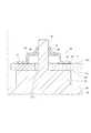
本実施形態の特徴である基板31の固定構造について、図2及び図3を参照して説明する。図2は、複数のボス26のうちの1つと、これを挟持する係止部材40とを拡大して示す断面図である。図3は、ボス26及び係止部材40を示す斜視図である。(Fixing the board)
A fixing structure of the
基板31は、係止部材40を介してフレーム部材20に固定されている。以下、係止部材40の構成について説明する。
係止部材40は、導電性のよい金属等により形成されており、一対の固定部41、凸部42、及び、一対の爪部43を有している。
一対の固定部41は、基板31に半田付けされることによって固定されている。また、一対の固定部41は、基板31において露出した配線部38に接続されており、配線部38は、グランドラインに接続されている。すなわち、係止部材40は、グランドラインに接続されている。The
The locking
The pair of fixing
凸部42は、所謂「コの字状(角張ったU字状)」に形成されており、一対の固定部41の間で基板31との間に空間を有している。凸部42には、フレーム部材20のボス26が挿通するボス挿通孔44が形成されている。
一対の爪部43は、挿通孔44を間に挟んで互いに対向しており、凸部42から基板31とは反対側に向かって伸びている。The
The pair of
一対の爪部43は、ボス26に弾性接触することにより、ボス26を両側から挟持している。また、凸部42のうち、挿通孔44を間に挟む2つの縁部分45(図3参照)は、一対の爪部43とは異なる方向においてボス26を両側から支持している。 The pair of
係止部材40は、弾性を有する金属板材に、切り込み加工及び折り曲げ加工を施すことによって形成可能である。例えば、金属板材に対してH型に切り込みを入れ、この切り
込み部分を折り曲げることによって、一対の爪部43とその間の挿通孔44とが形成され、金属板材の両端をクランク状に折り曲げることによって、一対の固定部41とその間の凸部42とが形成される。The locking
基板31をフレーム部材20に固定するとき、基板31に固定された係止部材40にボス26を圧入しつつ、基板支持部25の端面251に基板31が接触するまで、基板31をフレーム部材20に押し付ける。 When the
ボス26が係止部材40に圧入される前、一対の爪部43間の隙間は、当該隙間方向におけるボス26の径よりも小さい。ボス26が係止部材40に圧入されるとき、ボス26は、基板31のボス挿通孔315、及び、係止部材40の挿通孔44を順に挿通し、一対の爪部43の間に挿入される。このとき、一対の爪部43は、ボス26の挿入による押し圧を受けて弾性変形するが、自身の弾性復帰力によってボス26に両側から押し圧を加える。これにより、係止部材40とボス26とは強固に接続される。よって、基板31は、係止部材40を介してフレーム部材20に強固に固定される。 Before the
(効果)
本実施形態の駆動装置1の効果について説明する。
(1)本実施形態の駆動装置1は、巻線組13が巻回されたステータ12、ステータ12に対して相対回転可能に設けられたロータ15、及び、ロータ15と共に回転するシャフト16を有するモータ10と、モータ10の軸方向の一方側に設けられ、巻線組13への通電を制御する電子部品32〜37が実装された基板31を有するコントローラ30と、基板31に対向して配置されており、基板31を接触支持している基板支持部25を有するフレーム部材20と、フレーム部材20から基板31側に突出しているボス26と、基板31に固定され、ボス26を挟持している弾性変形可能な複数の爪部43を有する係止部材40と、を備える。(effect)
The effect of the
(1) The
駆動装置1を製造するとき、上述したように、フレーム部材20から突出しているボス26を基板31に固定された係止部材40に圧入しつつ、基板支持部25に基板31が接触するまで、基板31をフレーム部材20に押し付ける。すると、複数の爪部43は、ボス26に弾性接触することによりボス26を挟持する。基板31が基板支持部25に接触した状態でボス26が係止部材40に係止されることにより、基板31はフレーム部材20に固定される。 When manufacturing the
したがって、本実施形態によれば、工具を用いずに基板31をフレーム部材20に固定可能である駆動装置1が提供される。工具の作業スペースを確保する必要がないため、基板31における電子部品32〜37の実装スペースが制限されず、コントローラ30ひいては駆動装置1を小型化することができる。また、駆動装置1を製造するときの工数が削減される。
また、駆動装置1は、狭いスペースであっても搭載可能であるため、電動パワーステアリング装置に好適に適用される。Therefore, according to this embodiment, the
Moreover, since the
(2)本実施形態において、係止部材40は、基板31のフレーム部材20側とは反対側の面である第2主面312に設けられている。また、ボス26は、基板支持部25から突出し、基板31に形成されたボス挿通孔315を挿通して係止部材40に挟持されている
上記構成によれば、基板31は基板支持部25と係止部材40との間に挟まれるため、より安定して固定されている。(2) In the present embodiment, the locking
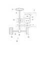
(3)本実施形態の駆動装置1では、ロータ15の回転やスイッチング素子32のスイッチング等によりノイズが生じる。ここで、駆動装置1に生じるノイズについて、図4を参照して説明する。図4は、駆動装置1の回路図と断面図とを組み合わせた模式的な図であり、二系統のうち一系統の巻線組13に接続される電子部品を代表的に示している。なお、図4では、電子部品と巻線組13とを接続するラインは図示を省略している。(3) In the
図4に示すように、6個のスイッチング素子321〜326は、ブリッジ接続されてインバータ320を構成している。インバータ320は、電源ラインLpを経由してバッテリ109の正極側に接続され、グランドラインLgを経由してバッテリ109の負極側に接続されている。コンデンサ36は、インバータ320の入力側に並列に接続されており、チョークコイル37は、バッテリ109とコンデンサ36の正極側との間に接続されている。 As shown in FIG. 4, the six switching
図4では、駆動装置1に生じるノイズの伝播経路を破線によって示している。ノイズは、ロータ15とステータ12との間に生じる浮遊容量C11または基板31とフレーム部材20との間の浮遊容量C12を介して、モータケース11に伝播され、コモンモードノイズとして、車体グランド等を経由してバッテリ109に伝播される虞がある。また、駆動装置1に発生したノイズがモータケース11を経由して駆動装置1の外部(例えば車体等)に伝播されると、車載ラジオのアンテナに伝播され、ラジオノイズの原因となる虞がある。 In FIG. 4, a propagation path of noise generated in the
そこで、本実施形態において、係止部材40は、導電性材料によって構成され、基板31に設けられたグランドラインLgに接続されており、フレーム部材20は、係止部材40を介してグランドラインLgに導通している。 Therefore, in the present embodiment, the locking
このような構成によれば、上述の浮遊容量C11、C12もグランドラインLgに電気的に接続される。このため、駆動装置1に発生したノイズは、ノーマルモードノイズになり、コンデンサ36及びチョークコイル37により形成されるフィルタ回路にて低減され得る。 According to such a configuration, the above-described stray capacitances C11 and C12 are also electrically connected to the ground line Lg. For this reason, noise generated in the
したがって、本実施形態によれば、コモンモードノイズが低減されるため、コモンモードノイズに対する対策を省略、或いは、簡略化することができる。また、フレーム部材20を経由して駆動装置1の外部へ漏れるノイズが低減されるため、駆動装置1からのノイズ漏れに起因するラジオノイズを低減することができる。 Therefore, according to the present embodiment, since common mode noise is reduced, measures against common mode noise can be omitted or simplified. Further, since noise leaking outside the driving
[第2実施形態]
本発明の第2実施形態による駆動装置を図5に基づいて説明する。図5は、第1実施形態の図2に対応する図である。[Second Embodiment]
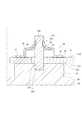
A driving apparatus according to a second embodiment of the present invention will be described with reference to FIG. FIG. 5 is a diagram corresponding to FIG. 2 of the first embodiment.
第1実施形態では、ボス26がフレーム部材20の一部として一体に形成されているが、第2実施形態では、ボス260がフレーム部材20とは別体として形成されている。ボス260は、例えばフレーム部材20の基板支持部25に形成された溝252に嵌合することによって、基板支持部25に固定されている。 In the first embodiment, the
また、第2実施形態では、ボス260の側面263に溝267が形成されており、係止部材40の爪部43が溝267に係合している。よって、ボス260が係止部材40から抜けることが防止される。よって、基板31がより確実にフレーム部材20に固定される。 In the second embodiment, the
また、ボス260がフレーム部材20とは別部材であるため、ボス26の側面263に溝267を加工しやすい。さらに、第1実施形態で説明した効果も同様に得られる。
なお、溝267はボス260の側面263の全周でなくともよく、各爪部43に対応して形成されていてもよい。Further, since the
The
[第3実施形態]
本発明の第3実施形態による駆動装置を図6及び図7に基づいて説明する。図6は、第1実施形態の図2に対応する図である。[Third Embodiment]
A driving apparatus according to a third embodiment of the present invention will be described with reference to FIGS. FIG. 6 is a diagram corresponding to FIG. 2 of the first embodiment.
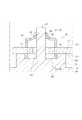
第3実施形態の係止部材60は、一対の固定部61、凸部62、及び、一対の爪部63を有している。
一対の固定部61は、それぞれ、2つの圧入端610から構成されている。圧入端610は、凸部62から基板31側に延びており、圧入端610自身の弾性変形を可能にする貫通穴613を有する。凸部62及び一対の爪部63の構成については、第1実施形態と同様である。The locking
Each of the pair of fixing
基板31には、第1実施形態の配線部38とは異なり、金属メッキ392が施された貫通孔39が形成されている。貫通孔39には、係止部材60の圧入端610が圧入される。 Unlike the
また、第3実施形態において、基板支持部25の端面251には、モータ10側に凹んでいる逃し溝253が形成されている。逃し溝253には、係止部材60の圧入端610の端部が入り込む。
ボス27は、逃し溝253の底面から基板31側に突出しており、一対の爪部63に挟持されている。In the third embodiment, the
The
第3実施形態では、係止部材60が基板31にプレスフィット接続されるため、半田付け作業を必要としない。よって、駆動装置1を製造するときの工数がより削減される。また、第1実施形態で説明した効果も同様に得られる。 In the third embodiment, since the locking
[第4実施形態]
本発明の第4実施形態による駆動装置を図8に基づいて説明する。図8は、第1実施形態の図2に対応する図である。[Fourth Embodiment]
A driving apparatus according to a fourth embodiment of the present invention will be described with reference to FIG. FIG. 8 is a diagram corresponding to FIG. 2 of the first embodiment.
第4実施形態において、基板支持部25は、端面251からモータ10側に凹んでいる凹部255を有している。基板支持部25の凹部255の内側には、ボス29が配置されている。ボス29は、凹部255の底面から基板31側に突出している。 In the fourth embodiment, the
第4実施形態の係止部材70は、基板31の第1主面311に固定されており、基板支持部25の凹部255の内側に収容されている。
また、係止部材70は、一対の固定部71、凸部72、及び、一対の爪部73を有している。一対の爪部73は、凸部72の挿通孔74を間に挟んで互いに対向しており、凸部72から基板31側に向かって伸びている。すなわち、一対の爪部73は、凸部72の内側空間に向かって延びてる。一対の固定部71及び凸部72の構成については、第1実施形態と同様である。The locking
The locking
基板31には、第1実施形態とは異なり、ボス挿通孔が形成されていない。ボス29は、基板31を経由せずに係止部材70に圧入されている。ボス29の端面291は、基板31との間に隙間を有するように、基板31に対面している。 Unlike the first embodiment, the
第4実施形態によれば、基板31にボス挿通孔を設ける加工を行わずとも良い。また、ボス29の圧入時、係止部材70を基板31に押し付ける方向に力が加わるため、圧入時の力によって係止部材70が基板31から外れる恐れがない。また、第1実施形態で説明した(2)以外の効果も同様に得られる。 According to the fourth embodiment, it is not necessary to perform the process of providing the boss insertion hole in the
(他の実施形態)
(ア)上記実施形態における係止部材40、60、70の構造は一例であり、本発明の係止部材は、ボス26を挟持する弾性変形可能な爪部を有するものであれば、特に限定されない。例えば、他の実施形態では、複数の爪部43、63、73は、それぞれ別体として構成されていてもよい。また、爪部43、63、73が3つ以上であってもよい。(Other embodiments)
(A) The structure of the locking
(イ)他の実施形態の駆動装置において、ボス26、27、29、260及び係止部材40、60、70の組み合わせは、少なくとも1つあればよい。
また、他の実施形態において、各実施形態のボス26、27、29、260及び係止部材40、60、70の構成が組み合わされてもよい。例えば、第3、第4実施形態のボス27、29は、第2実施形態のボス260のように構成されてもよい。また、第3実施形態の係止部材60は、第4実施形態の係止部材70ように、基板31の第1主面311側に固定されてもよい。(A) In the drive device according to another embodiment, there may be at least one combination of the
Moreover, in other embodiment, the structure of the boss |
(ウ)他の実施形態において、係止部材40、60、70は、グランドラインLgに接続されておらず、フレーム部材20は、係止部材40、60、70を介してグランドラインLgに導通していなくともよい。(C) In other embodiments, the locking
(エ)上記実施形態ではフレーム部材20が突起状の基板支持部25を有しているが、本発明はこれに限られない。他の実施形態では、フレーム部材20が突起状の基板支持部25を有さず、フレーム本体24が「基板支持部」として基板31を接触支持していてもよい。(D) In the above embodiment, the
(オ)本発明のフレーム部材は、上記実施形態のようにモータ10の筐体の一部として構成されてもよいし、モータ10の筐体とは別体として構成されてもよい。(E) The frame member of the present invention may be configured as a part of the casing of the
(カ)上記実施形態では、モータ10は3相交流モータである。他の実施形態では、モータ10は、ブラシ付直流モータであってもよいし、4相以上の多相交流モータであってもよい。また、巻線組13は、2系統に限らず、1系統でもよいし、3系統以上としてもよい。(F) In the above embodiment, the
(キ)上記実施形態では、駆動装置1は、電動パワーステアリング装置に適用される。他の実施形態では、駆動装置1は電動パワーステアリング装置以外の装置に適用されてもよい。
以上、本発明はこのような実施形態に限定されるものではなく、発明の趣旨を逸脱しない範囲において、種々の形態で実施することができる。(G) In the above embodiment, the
As mentioned above, this invention is not limited to such embodiment, In the range which does not deviate from the meaning of invention, it can implement with a various form.
1・・・駆動装置
10・・・モータ
12・・・ステータ
15・・・ロータ
16・・・シャフト
20・・・フレーム部材
25・・・基板支持部
26、27、29、260・・・ボス(突起部)
30・・・コントローラ
40、60、70・・・係止部材
43、63、73・・・爪部DESCRIPTION OF
30 ...
Claims (8)
Translated fromJapanese前記モータの軸方向の一方側に設けられ、前記巻線への通電を制御する電子部品(32〜37)が実装された基板(31)を有するコントローラ(30)と、
前記基板に対向して配置されており、前記基板を接触支持している基板支持部(25)を有するフレーム部材(20)と、
前記フレーム部材から前記基板側に突出している突起部(26、27、29、260)と、
前記基板に固定され、前記突起部を挟持している弾性変形可能な複数の爪部(43、63、73)を有する係止部材(40、60、70)と、
を備える駆動装置。A motor (10) having a stator (12) around which a winding (13) is wound, a rotor (15) provided rotatably relative to the stator, and a shaft (16) rotating together with the rotor;
A controller (30) having a substrate (31) mounted on one side in the axial direction of the motor and mounted with electronic components (32 to 37) for controlling energization to the winding;
A frame member (20) having a substrate support portion (25) disposed opposite to the substrate and supporting the substrate in contact;
A protrusion (26, 27, 29, 260) protruding from the frame member toward the substrate;
A locking member (40, 60, 70) having a plurality of elastically deformable claw portions (43, 63, 73) fixed to the substrate and sandwiching the protruding portion;
A drive device comprising:
前記フレーム部材は、前記係止部材を介して前記グランドラインに導通していることを特徴とする請求項1に記載の駆動装置。The locking member is made of a conductive material and is connected to a ground line (Lg) provided on the substrate.
The drive device according to claim 1, wherein the frame member is electrically connected to the ground line via the locking member.
前記突起部(26、27、260)は、前記基板支持部から突出し、前記基板に形成された孔(315)を挿通して前記係止部材に挟持されている請求項1〜3のいずれか一項に記載の駆動装置。The locking member (40, 60, 260) is provided on a surface (312) opposite to the frame member side of the substrate,
The said protrusion part (26,27,260) protrudes from the said board | substrate support part, penetrates the hole (315) formed in the said board | substrate, and is clamped by the said locking member. The drive device according to one item.
前記係止部材(70)は、前記基板の前記フレーム部材側の面(311)に設けられ、前記凹部に収容されている請求項1〜3のいずれか一項に記載の駆動装置。The substrate support portion has a recess (255) that is recessed on the motor side and in which the protruding portion (29) is disposed,
The drive device according to any one of claims 1 to 3, wherein the locking member (70) is provided on a surface (311) of the substrate on the frame member side and is accommodated in the recess.
Priority Applications (4)
| Application Number | Priority Date | Filing Date | Title |
|---|---|---|---|
| JP2014258883AJP6485032B2 (en) | 2014-12-22 | 2014-12-22 | DRIVE DEVICE AND ELECTRIC POWER STEERING DEVICE USING THE SAME |
| US14/971,315US10033253B2 (en) | 2014-12-22 | 2015-12-16 | Drive device |
| DE102015226511.0ADE102015226511B4 (en) | 2014-12-22 | 2015-12-22 | drive device |
| CN201510971437.4ACN105720748B (en) | 2014-12-22 | 2015-12-22 | Drive device |
Applications Claiming Priority (1)
| Application Number | Priority Date | Filing Date | Title |
|---|---|---|---|
| JP2014258883AJP6485032B2 (en) | 2014-12-22 | 2014-12-22 | DRIVE DEVICE AND ELECTRIC POWER STEERING DEVICE USING THE SAME |
Publications (2)
| Publication Number | Publication Date |
|---|---|
| JP2016119794Atrue JP2016119794A (en) | 2016-06-30 |
| JP6485032B2 JP6485032B2 (en) | 2019-03-20 |
Family
ID=56097548
Family Applications (1)
| Application Number | Title | Priority Date | Filing Date |
|---|---|---|---|
| JP2014258883AActiveJP6485032B2 (en) | 2014-12-22 | 2014-12-22 | DRIVE DEVICE AND ELECTRIC POWER STEERING DEVICE USING THE SAME |
Country Status (4)
| Country | Link |
|---|---|
| US (1) | US10033253B2 (en) |
| JP (1) | JP6485032B2 (en) |
| CN (1) | CN105720748B (en) |
| DE (1) | DE102015226511B4 (en) |
Cited By (2)
| Publication number | Priority date | Publication date | Assignee | Title |
|---|---|---|---|---|
| JP2018126043A (en)* | 2017-02-03 | 2018-08-09 | 日本電産株式会社 | motor |
| JP2020181911A (en)* | 2019-04-25 | 2020-11-05 | 株式会社豊田自動織機 | Board connection structure |
Families Citing this family (6)
| Publication number | Priority date | Publication date | Assignee | Title |
|---|---|---|---|---|
| US9641112B2 (en)* | 2014-12-10 | 2017-05-02 | Clark Equipment Company | Protection method for a generator |
| DE102017212500A1 (en)* | 2016-12-08 | 2018-06-14 | Audi Ag | Final drive for a motor vehicle and axle drive device |
| JPWO2018150743A1 (en)* | 2017-02-20 | 2019-12-12 | 日本電産株式会社 | motor |
| US10840776B2 (en) | 2017-05-27 | 2020-11-17 | Actuator Electric Motors | Self-contained brushless motor and brushless controller |
| DE102019207582A1 (en)* | 2019-05-23 | 2020-11-26 | Siemens Schweiz Ag | SMD-compatible THT holder |
| KR102789625B1 (en)* | 2020-01-02 | 2025-04-01 | 엘지이노텍 주식회사 | Motor |
Citations (7)
| Publication number | Priority date | Publication date | Assignee | Title |
|---|---|---|---|---|
| JPH0338415U (en)* | 1989-08-26 | 1991-04-15 | ||
| JPH0340695U (en)* | 1989-08-31 | 1991-04-18 | ||
| JPH07212998A (en)* | 1994-01-13 | 1995-08-11 | Shibaura Eng Works Co Ltd | Connection structure |
| US5740019A (en)* | 1994-09-06 | 1998-04-14 | Samsung Electronics Co., Ltd. | Apparatus for mounting a printed circuit board in a monitor case |
| JP2000175403A (en)* | 1998-12-03 | 2000-06-23 | Sankyo Seiki Mfg Co Ltd | Mounting structure of motor substrate in motor |
| JP2014033541A (en)* | 2012-08-03 | 2014-02-20 | Denso Corp | Rotating electrical machine and electric power steering apparatus using the same |
| JP2014101823A (en)* | 2012-11-21 | 2014-06-05 | Mitsubishi Heavy Ind Ltd | Instrument having heat sink |
Family Cites Families (15)
| Publication number | Priority date | Publication date | Assignee | Title |
|---|---|---|---|---|
| US4380359A (en)* | 1980-12-05 | 1983-04-19 | General Motors Corporation | Electrical connector for an instrument panel |
| US4797110A (en)* | 1986-09-08 | 1989-01-10 | General Motors Corporation | Printed circuit board with integral electrical connector and method for making it using wave soldering |
| JP2877358B2 (en) | 1989-07-07 | 1999-03-31 | 株式会社東芝 | Multistage connection switch network |
| DE4034423C2 (en)* | 1989-10-30 | 1998-10-08 | Amp Inc | Circuit board contact |
| US6259032B1 (en)* | 1999-05-28 | 2001-07-10 | Agilent Technologies Inc. | Circuit board grounding scheme |
| JP2005086136A (en) | 2003-09-11 | 2005-03-31 | Calsonic Kansei Corp | Substrate fixing structure and rotation sensor therewith |
| TWM292820U (en)* | 2005-12-09 | 2006-06-21 | Innolux Display Corp | Electronic device having grounded structure |
| JP4652246B2 (en)* | 2006-02-13 | 2011-03-16 | 矢崎総業株式会社 | Motor terminal connection structure |
| JP2008305868A (en) | 2007-06-05 | 2008-12-18 | Densei Lambda Kk | Fixing structure for circuit board |
| US7581965B1 (en)* | 2008-05-01 | 2009-09-01 | Commscope, Inc. Of North Carolina | Bottom entry interconnection element for connecting components to a circuit board |
| DE112009000845B4 (en)* | 2008-06-13 | 2016-02-25 | Mitsubishi Electric Corp. | engine assembly |
| DE102010002793A1 (en)* | 2010-03-11 | 2011-09-15 | Robert Bosch Gmbh | Drive device with an electric drive motor and a transmission |
| JP5316469B2 (en)* | 2010-04-16 | 2013-10-16 | 株式会社デンソー | Electric motor drive device and electric device using the same |
| US8760091B2 (en)* | 2011-03-18 | 2014-06-24 | Merkle-Korff Industries, Inc. | Multifunction PMDC motor apparatus and method thereof |
| DE102013208177A1 (en) | 2013-05-03 | 2014-11-06 | Robert Bosch Gmbh | Housing assembly with a housing component for an electrical machine and an electrical circuit board |
- 2014
- 2014-12-22JPJP2014258883Apatent/JP6485032B2/enactiveActive
- 2015
- 2015-12-16USUS14/971,315patent/US10033253B2/enactiveActive
- 2015-12-22DEDE102015226511.0Apatent/DE102015226511B4/enactiveActive
- 2015-12-22CNCN201510971437.4Apatent/CN105720748B/enactiveActive
Patent Citations (7)
| Publication number | Priority date | Publication date | Assignee | Title |
|---|---|---|---|---|
| JPH0338415U (en)* | 1989-08-26 | 1991-04-15 | ||
| JPH0340695U (en)* | 1989-08-31 | 1991-04-18 | ||
| JPH07212998A (en)* | 1994-01-13 | 1995-08-11 | Shibaura Eng Works Co Ltd | Connection structure |
| US5740019A (en)* | 1994-09-06 | 1998-04-14 | Samsung Electronics Co., Ltd. | Apparatus for mounting a printed circuit board in a monitor case |
| JP2000175403A (en)* | 1998-12-03 | 2000-06-23 | Sankyo Seiki Mfg Co Ltd | Mounting structure of motor substrate in motor |
| JP2014033541A (en)* | 2012-08-03 | 2014-02-20 | Denso Corp | Rotating electrical machine and electric power steering apparatus using the same |
| JP2014101823A (en)* | 2012-11-21 | 2014-06-05 | Mitsubishi Heavy Ind Ltd | Instrument having heat sink |
Cited By (3)
| Publication number | Priority date | Publication date | Assignee | Title |
|---|---|---|---|---|
| JP2018126043A (en)* | 2017-02-03 | 2018-08-09 | 日本電産株式会社 | motor |
| WO2018143328A1 (en)* | 2017-02-03 | 2018-08-09 | 日本電産株式会社 | Motor |
| JP2020181911A (en)* | 2019-04-25 | 2020-11-05 | 株式会社豊田自動織機 | Board connection structure |
Also Published As
| Publication number | Publication date |
|---|---|
| US20160181883A1 (en) | 2016-06-23 |
| JP6485032B2 (en) | 2019-03-20 |
| DE102015226511B4 (en) | 2022-10-27 |
| DE102015226511A1 (en) | 2016-06-23 |
| US10033253B2 (en) | 2018-07-24 |
| CN105720748A (en) | 2016-06-29 |
| CN105720748B (en) | 2020-02-14 |
Similar Documents
| Publication | Publication Date | Title |
|---|---|---|
| JP6485032B2 (en) | DRIVE DEVICE AND ELECTRIC POWER STEERING DEVICE USING THE SAME | |
| JP6443055B2 (en) | Drive device and drive device manufacturing method | |
| JP5951067B1 (en) | Electric power steering device | |
| JP6117577B2 (en) | Electronic control unit | |
| CN111264021B (en) | Electric drives and electric power steering | |
| JP2019068543A (en) | Motor control device and electric power steering device | |
| WO2015198476A1 (en) | Integrated electric power steering device, and manufacturing method thereof | |
| JP2014183615A (en) | Rotary electric machine | |
| US9293970B2 (en) | Control device and motor unit including the control device | |
| JP7063747B2 (en) | Electric drive device and electric power steering device | |
| JP5563513B2 (en) | Electric power steering device | |
| JP2014151850A (en) | Electronic control device | |
| JP2020188556A (en) | motor | |
| JP6445066B2 (en) | Electronic control unit | |
| JP2014169079A (en) | Electric power steering device | |
| WO2020008905A1 (en) | Electrical drive device and electrical power steering device | |
| JP6099915B2 (en) | Electronic control unit | |
| JP7561985B2 (en) | Motor Control Device | |
| WO2022196456A1 (en) | Drive device | |
| JP7041546B2 (en) | Electronic control device and electric drive device | |
| JP6059771B2 (en) | Electric power steering device | |
| JP5566357B2 (en) | Motor drive device | |
| JP6248173B2 (en) | Electric power steering device | |
| WO2025158951A1 (en) | Drive device | |
| JP2022026387A (en) | Motor control device and electric power steering device |
Legal Events
| Date | Code | Title | Description |
|---|---|---|---|
| A621 | Written request for application examination | Free format text:JAPANESE INTERMEDIATE CODE: A621 Effective date:20170519 | |
| A131 | Notification of reasons for refusal | Free format text:JAPANESE INTERMEDIATE CODE: A131 Effective date:20180320 | |
| A977 | Report on retrieval | Free format text:JAPANESE INTERMEDIATE CODE: A971007 Effective date:20180322 | |
| A521 | Request for written amendment filed | Free format text:JAPANESE INTERMEDIATE CODE: A523 Effective date:20180521 | |
| A131 | Notification of reasons for refusal | Free format text:JAPANESE INTERMEDIATE CODE: A131 Effective date:20180911 | |
| A521 | Request for written amendment filed | Free format text:JAPANESE INTERMEDIATE CODE: A523 Effective date:20181031 | |
| TRDD | Decision of grant or rejection written | ||
| A01 | Written decision to grant a patent or to grant a registration (utility model) | Free format text:JAPANESE INTERMEDIATE CODE: A01 Effective date:20190122 | |
| A61 | First payment of annual fees (during grant procedure) | Free format text:JAPANESE INTERMEDIATE CODE: A61 Effective date:20190204 | |
| R151 | Written notification of patent or utility model registration | Ref document number:6485032 Country of ref document:JP Free format text:JAPANESE INTERMEDIATE CODE: R151 | |
| R250 | Receipt of annual fees | Free format text:JAPANESE INTERMEDIATE CODE: R250 | |
| R250 | Receipt of annual fees | Free format text:JAPANESE INTERMEDIATE CODE: R250 | |
| R250 | Receipt of annual fees | Free format text:JAPANESE INTERMEDIATE CODE: R250 | |
| R250 | Receipt of annual fees | Free format text:JAPANESE INTERMEDIATE CODE: R250 |