JP2016118313A - refrigerator - Google Patents
refrigeratorDownload PDFInfo
- Publication number
- JP2016118313A JP2016118313AJP2014256891AJP2014256891AJP2016118313AJP 2016118313 AJP2016118313 AJP 2016118313AJP 2014256891 AJP2014256891 AJP 2014256891AJP 2014256891 AJP2014256891 AJP 2014256891AJP 2016118313 AJP2016118313 AJP 2016118313A
- Authority
- JP
- Japan
- Prior art keywords
- inner box
- duct
- duct cover
- engagement receiving
- refrigerator
- Prior art date
- Legal status (The legal status is an assumption and is not a legal conclusion. Google has not performed a legal analysis and makes no representation as to the accuracy of the status listed.)
- Pending
Links
- 210000000078clawAnatomy0.000claimsdescription18
- 239000011810insulating materialSubstances0.000claimsdescription13
- 238000007789sealingMethods0.000description14
- 238000001816coolingMethods0.000description10
- 238000007710freezingMethods0.000description10
- 230000008014freezingEffects0.000description10
- 238000005192partitionMethods0.000description8
- 230000015572biosynthetic processEffects0.000description7
- 238000009413insulationMethods0.000description7
- 239000006260foamSubstances0.000description6
- 235000013311vegetablesNutrition0.000description6
- 238000003825pressingMethods0.000description5
- 229920003002synthetic resinPolymers0.000description5
- 239000000057synthetic resinSubstances0.000description5
- 238000003780insertionMethods0.000description4
- 230000037431insertionEffects0.000description4
- 239000004743PolypropyleneSubstances0.000description3
- 238000005057refrigerationMethods0.000description3
- KAKZBPTYRLMSJV-UHFFFAOYSA-NButadieneChemical compoundC=CC=CKAKZBPTYRLMSJV-UHFFFAOYSA-N0.000description2
- 239000004793PolystyreneSubstances0.000description2
- PPBRXRYQALVLMV-UHFFFAOYSA-NStyreneChemical compoundC=CC1=CC=CC=C1PPBRXRYQALVLMV-UHFFFAOYSA-N0.000description2
- 238000006073displacement reactionMethods0.000description2
- 235000013305foodNutrition0.000description2
- NNPPMTNAJDCUHE-UHFFFAOYSA-NisobutaneChemical compoundCC(C)CNNPPMTNAJDCUHE-UHFFFAOYSA-N0.000description2
- 239000003507refrigerantSubstances0.000description2
- 230000003014reinforcing effectEffects0.000description2
- NLHHRLWOUZZQLW-UHFFFAOYSA-NAcrylonitrileChemical compoundC=CC#NNLHHRLWOUZZQLW-UHFFFAOYSA-N0.000description1
- 229920005830Polyurethane FoamPolymers0.000description1
- 229910000831SteelInorganic materials0.000description1
- 229920000122acrylonitrile butadiene styrenePolymers0.000description1
- 238000007664blowingMethods0.000description1
- 229920006026co-polymeric resinPolymers0.000description1
- 230000006835compressionEffects0.000description1
- 238000007906compressionMethods0.000description1
- 230000001276controlling effectEffects0.000description1
- 230000000694effectsEffects0.000description1
- 230000005489elastic deformationEffects0.000description1
- 230000002708enhancing effectEffects0.000description1
- 230000001747exhibiting effectEffects0.000description1
- 239000004794expanded polystyreneSubstances0.000description1
- 238000009434installationMethods0.000description1
- 239000001282iso-butaneSubstances0.000description1
- 239000000463materialSubstances0.000description1
- 238000000034methodMethods0.000description1
- 238000000465mouldingMethods0.000description1
- -1polypropylenePolymers0.000description1
- 229920001155polypropylenePolymers0.000description1
- 229920006327polystyrene foamPolymers0.000description1
- 229920002635polyurethanePolymers0.000description1
- 239000004814polyurethaneSubstances0.000description1
- 239000011496polyurethane foamSubstances0.000description1
- 230000001105regulatory effectEffects0.000description1
- 229920005989resinPolymers0.000description1
- 239000011347resinSubstances0.000description1
- 239000010959steelSubstances0.000description1
- 230000008719thickeningEffects0.000description1
Images


Landscapes
- Cold Air Circulating Systems And Constructional Details In Refrigerators (AREA)
Abstract
Description
Translated fromJapanese本発明は、貯蔵室内に食品等を冷却保存する冷蔵庫に関し、特に、冷却器で冷却された空気を貯蔵室に供給するための供給風路を有する冷蔵庫に関する。 The present invention relates to a refrigerator that stores food or the like in a storage room in a cold state, and particularly relates to a refrigerator that has a supply air passage for supplying air cooled by a cooler to a storage room.
従来、冷却器で冷却された空気を貯蔵室に供給するための供給風路を、冷蔵庫の断熱箱体を構成する内箱と、内箱の内部(貯蔵室側)に設けられるダクト部材との間に形成した冷蔵庫が知られている(例えば、特許文献1、特許文献2)。 Conventionally, a supply air passage for supplying air cooled by a cooler to a storage room is composed of an inner box constituting a heat insulating box body of a refrigerator, and a duct member provided in the inner box (on the storage room side). A refrigerator formed between them is known (for example,
特許文献1に開示された冷蔵庫は、冷蔵室の内部に、冷蔵室背面パネルと発泡断熱材とから構成される冷蔵室用ダクトを備えている。発泡断熱材には、冷気通路を形成する発泡断熱材凸部が形成されており、冷蔵室用ダクトは、プッシュリベットとグロメットリベットを用いて内箱に取り付けられる。これにより、発泡断熱材凸部が内箱の内面に押し付けられ、発泡断熱材と内箱との間に冷気通路が形成される。 The refrigerator disclosed in
また、特許文献2に開示された冷蔵庫は、内方に開口する一対の溝部を備える内箱と、内箱の内方に取り付けられて冷気を案内する風路を形成する風路形成体と、を備える。風路形成体の左右両側には内箱に向けて突出する嵌入部が形成され、該嵌入部は内箱の溝部に嵌め込まれる。これにより、内箱と風路形成体との間に風路が形成される。 Moreover, the refrigerator disclosed in
しかしながら、従来技術の冷蔵庫では、冷気の供給風路を形成するダクト部材の取り付け及び取り外しを容易にし、且つ供給風路のシール性を高める観点において更に改善すべき点があった。 However, in the refrigerator of the prior art, there was a point that should be further improved in terms of facilitating attachment and detachment of the duct member forming the cold air supply air passage and enhancing the sealing performance of the air supply passage.
具体的には、特許文献1に開示された冷蔵庫のように、冷蔵室用ダクトをリベット等によって内箱に固定する場合、リベット等の近傍、即ちリベット等によって冷蔵室用ダクトが内箱に押圧されている部分は、シール性を確保できる。しかし、リベット等から離れた部分は、内箱への押圧力が弱くなるので、リベット等の近傍に比べてシール性能が低くなるという問題点があった。 Specifically, when the refrigerator compartment duct is fixed to the inner box with a rivet or the like as in the refrigerator disclosed in
特に、長尺のダクト部材では、意匠的な制約から上下方向の中間部にリベット等を取り付けられない場合もある。そのような場合、ダクト部材の上部及び下部をリベット等で止めても、中間部においてダクト部材と内箱との間に間隙が発生し易い。そのため、その間隙を介して供給風路の冷気が漏れてしまう。また、リベット等による固定箇所を増やすと、部品数が増加し、供給風路の組み立てが煩雑になる。 In particular, in the case of a long duct member, a rivet or the like may not be attached to an intermediate portion in the vertical direction due to design restrictions. In such a case, even if the upper and lower portions of the duct member are stopped with rivets or the like, a gap is likely to be generated between the duct member and the inner box at the intermediate portion. Therefore, the cold air in the supply air passage leaks through the gap. Further, when the number of fixing points by rivets or the like is increased, the number of parts increases and the assembly of the supply air passage becomes complicated.
また、特許文献2に開示された冷蔵庫のように、風路形成体に形成される嵌入部を、内箱に形成される溝部に挿入して、風路形成体を内箱に固定する場合、内箱の成形が難しいという問題点があった。 Moreover, like the refrigerator disclosed in
即ち、風路形成体を内箱に固定するためには、風路形成体の嵌入部に突起部を形成すると共に、内箱に形成される溝部には、前記突起部に係合するための突起を形成する必要があった。つまり、内箱の溝部は、アンダーカット形状に形成される必要があり、その加工が困難であった。 That is, in order to fix the air passage formation body to the inner box, a protrusion is formed in the fitting portion of the air passage formation body, and a groove formed in the inner box is used to engage the protrusion. It was necessary to form protrusions. That is, the groove portion of the inner box needs to be formed in an undercut shape, and the processing is difficult.
また、断熱箱体の成形においては、発泡される断熱材によって内箱が押されて変形し易いので、内箱の寸法精度を高く維持することが難しい。内箱の寸法精度が低いと、風路形成体と内箱との組み立てが困難になり、両者の間に間隙が発生して供給風路のシール性が悪くなる。 Further, in forming the heat insulating box, the inner box is easily pushed and deformed by the foamed heat insulating material, so it is difficult to maintain high dimensional accuracy of the inner box. If the dimensional accuracy of the inner box is low, it becomes difficult to assemble the air path forming body and the inner box, and a gap is generated between the two, resulting in poor sealing of the supply air path.
また、特許文献2に開示された冷蔵庫のように、風路形成体を構成する発泡ポリスチレンからなるダクトに嵌入部を形成する場合には、嵌入部の強度が弱く破損し易い。そのため、風路形成体を取り外す際に嵌入部が破損する恐れがあり、風路形成体の取り外しが困難であった。 Moreover, like the refrigerator disclosed by
本発明は、上記の事情に鑑みてなされたものであり、ダクト部材の取り付け及び取り外しを容易に行うことができ、且つ風路の気密性を高めることができる冷蔵庫を提供することを目的とする。 This invention is made | formed in view of said situation, and it aims at providing the refrigerator which can perform attachment and removal of a duct member easily, and can improve the airtightness of an air path. .
本発明の冷蔵庫は、外箱と内箱との間に断熱材が充填されて前方が開口する断熱箱体と、前記内箱の前面に設けられて前記内箱との間に風路を形成するダクト部材と、前記ダクト部材の前面に設けられて前記ダクト部材を覆うダクトカバーと、前記内箱に固定されて前記ダクトカバーが係合される係合受部材と、を備え、前記内箱には、前記ダクト部材の左右外側に前記係合受部材を取り付ける取付孔が形成され、前記係合受部材は、前記内箱の背面に当接する基部と、前記基部から前方に突設されて前記取付孔に挿通される係合受部と、前記係合受部から左右方向の外側に向かって突設される突起部と、を有し、前記ダクトカバーには、その左右に係合部が形成され、前記係合部は、左右方向の内側に向かって突設される爪部を有し、前記係合受部材に対して左右方向の外側から係合することを特徴とする。 The refrigerator of the present invention is provided with a heat insulating material between the outer box and the inner box so that the front is opened, and the air box is formed between the inner box and the front surface of the inner box. A duct member provided on a front surface of the duct member and covering the duct member; and an engagement receiving member fixed to the inner box and engaged with the duct cover. Mounting holes for attaching the engagement receiving member are formed on the left and right outer sides of the duct member, and the engagement receiving member protrudes forward from the base and a base that contacts the back surface of the inner box. An engagement receiving portion that is inserted through the mounting hole; and a projection that protrudes outward from the engagement receiving portion in the left-right direction, and the duct cover includes engagement portions on the left and right sides thereof. And the engaging portion has a claw portion projecting inward in the left-right direction, Characterized by engaging from the outside in the lateral direction with respect to engagement receiving member.
また、本発明の冷蔵庫は、前記内箱には、前記ダクト部材の左右外側に沿って上下方向に延在する凸部が形成されることを特徴とする。 Moreover, the refrigerator of the present invention is characterized in that the inner box is formed with a convex portion extending in the vertical direction along the left and right outer sides of the duct member.
また、本発明の冷蔵庫は、前記凸部が前記係合受部材の外側に形成されることを特徴とする。 The refrigerator according to the present invention is characterized in that the convex portion is formed outside the engagement receiving member.
また、本発明の冷蔵庫は、前記ダクトカバーには、後方に向かって突設されて前記ダクト部材の左右外側に沿って上下方向に延在するガイド部が形成され、前記係合部は、前記ガイド部に形成されることを特徴とする。 In the refrigerator of the present invention, the duct cover is provided with a guide portion that protrudes rearward and extends in the vertical direction along the left and right outer sides of the duct member. It is formed in a guide part.
また、本発明の冷蔵庫は、前記ダクトカバーと前記内箱とを固定する取付部材と、を有し、前記ダクトカバーは、その上部及び下部において前記取付部材によって前記内箱に固定され、前記係合部は、前記上部の取付部材よりも下方且つ前記下部の取付部材よりも上方に形成されることを特徴とする。 The refrigerator of the present invention includes an attachment member that fixes the duct cover and the inner box, and the duct cover is fixed to the inner box by the attachment member at an upper portion and a lower portion thereof, and the engagement member The joint portion is formed below the upper mounting member and above the lower mounting member.
また、本発明の冷蔵庫は、前記ダクトカバーの左右外側には、前記ダクトカバーの端部近傍が左右外側へ弾性変形することを許容する空間部が形成されることを特徴とする。 The refrigerator of the present invention is characterized in that a space that allows elastic deformation of the vicinity of the end of the duct cover to the left and right outer sides is formed on the left and right outer sides of the duct cover.
また、本発明の冷蔵庫は、前記ダクトカバーの左右の端部近傍を外側へ弾性変形させることよって、前記係合部と前記係合受部との係合が解除されることを特徴とする。 The refrigerator of the present invention is characterized in that the engagement between the engagement portion and the engagement receiving portion is released by elastically deforming the vicinity of the left and right end portions of the duct cover outward.
本発明の冷蔵庫によれば、内箱に係合受部材を取り付ける取付孔が形成される。係合受部材は、内箱の背面から取付孔に挿通され、内箱の内側にダクトカバーの係合部と係合するための係合受部を形成する。これにより、内箱にダクトカバーを取り付けるためのアンダーカット形状の溝等を形成する必要がなくなるので、内箱の形が単純になり、内箱の成形が容易になる。また、係合受部材を容易且つ高強度に固定できる。 According to the refrigerator of the present invention, the attachment hole for attaching the engagement receiving member to the inner box is formed. The engagement receiving member is inserted into the mounting hole from the back surface of the inner box, and forms an engagement receiving portion for engaging with the engagement portion of the duct cover inside the inner box. This eliminates the need to form an undercut groove or the like for attaching the duct cover to the inner box, thereby simplifying the shape of the inner box and facilitating the molding of the inner box. Further, the engagement receiving member can be fixed easily and with high strength.
また、係合部と係合受部材とを係合させることにより、ダクト部材と内箱との間に間隙が発生することを抑制して、供給風路のシール性能を高めることができる。また、係合部及び係合受部をダクト部材の左右に設けることによりダクト部材の左右でダクト部材と内箱との押し付け力を高め、高いシール性を発揮できる。 Further, by engaging the engaging portion and the engagement receiving member, it is possible to suppress the generation of a gap between the duct member and the inner box, and to improve the sealing performance of the supply air passage. Further, by providing the engaging portion and the engaging receiving portion on the left and right sides of the duct member, the pressing force between the duct member and the inner box can be increased on the left and right sides of the duct member, and high sealing performance can be exhibited.
また、ダクトカバーの係合部の爪部は、内側に向かって突設されており、係合受部に形成される突起部は、外側に向かって突設される。これにより、ダクトカバーを取り外す際に、ダクトカバーを左右に広げて係合部と係合受部材との係合を解除し、ダクトカバーを容易に取り外すことができる。また、取り外し時に、ダクトカバーの爪部に過大な力が作用しないので爪部の破損を防止できる。 Further, the claw portion of the engaging portion of the duct cover protrudes toward the inside, and the protrusion formed on the engagement receiving portion protrudes toward the outside. Thus, when removing the duct cover, the duct cover can be widened to the left and right to release the engagement between the engaging portion and the engagement receiving member, and the duct cover can be easily removed. Further, when removing, since an excessive force does not act on the claw portion of the duct cover, the claw portion can be prevented from being damaged.
また、本発明の冷蔵庫によれば、内箱の内側に、ダクト部材の左右外側に沿って上下方向に延在する凸部を備えている。これにより、ダクト部材及びダクトカバーを取り付ける際、ダクト部材やダクトカバーの位置決めが容易になる。 Moreover, according to the refrigerator of this invention, the convex part extended in the up-down direction along the left-right outer side of a duct member is provided inside the inner box. Thereby, when attaching a duct member and a duct cover, positioning of a duct member or a duct cover becomes easy.
また、本発明の冷蔵庫によれば、凸部は、係合受部材を取り付ける取付孔の外側に形成されている。これにより、ダクトカバーの係合部は、凸部の内側に挿入されることになり、凸部に案内されてダクトカバーの位置決めが容易になる。また、凸部によって係合部の過大な変位が規制されるので、係合部と係合受部との係合の外れを防止することができる。 Moreover, according to the refrigerator of this invention, the convex part is formed in the outer side of the attachment hole which attaches an engagement receiving member. Thereby, the engaging part of a duct cover will be inserted inside a convex part, and it will be guided by a convex part and positioning of a duct cover will become easy. Moreover, since the excessive displacement of the engaging part is regulated by the convex part, it is possible to prevent the engagement part and the engagement receiving part from being disengaged.
また、本発明の冷蔵庫によれば、ダクトカバーの内側にダクト部材を固定するためのガイド部が形成される。これにより、ダクト部材の位置決めが容易になる。また、ガイド部に係合部を形成することにより、ダクトカバー及びダクト部材の位置決めや取り付けが容易になる。 Moreover, according to the refrigerator of this invention, the guide part for fixing a duct member is formed inside a duct cover. Thereby, positioning of a duct member becomes easy. Further, by forming the engaging portion in the guide portion, positioning and attachment of the duct cover and the duct member are facilitated.
また、本発明の冷蔵庫によれば、ダクトカバーの上部近傍及び下部近傍を取付部材(ねじ等)によって固定し、上下方向の略中間部を係合部と係合受部とによって係合させる。これにより、取付部材(ねじ等)の個数が少なくても高いシール性を発揮できる。また、部品数を減らして取り付け作業を容易にできる。また、取付部材の個数が少ないので、意匠性も向上する。 Further, according to the refrigerator of the present invention, the vicinity of the upper portion and the lower portion of the duct cover are fixed by the attachment members (screws or the like), and the substantially intermediate portion in the vertical direction is engaged by the engaging portion and the engaging receiving portion. Thereby, even if the number of attachment members (screws etc.) is small, high sealing performance can be exhibited. In addition, the number of parts can be reduced to facilitate installation. Moreover, since the number of attachment members is small, the design is improved.
また、本発明の冷蔵庫によれば、ダクトカバーの左右外側には、ダクトカバーの端部近傍が左右外側へ弾性変形することを許容する空間部が形成される。これにより、ダクトカバーの端部を左右に拡げる作業のためのスペースが確保され、ダクトカバーの取り外しが容易になる。 Further, according to the refrigerator of the present invention, a space that allows the vicinity of the end of the duct cover to be elastically deformed to the left and right outside is formed on the left and right outside of the duct cover. Thereby, the space for the operation | work which expands the edge part of a duct cover to right and left is ensured, and the removal of a duct cover becomes easy.
また、本発明の冷蔵庫によれば、ダクトカバーの左右の端部近傍を外側へ弾性変形させることよって、係合部と係合受部との係合が解除される。そのため、ダクトカバーを容易に取り外すことができる。 Further, according to the refrigerator of the present invention, the engagement between the engagement portion and the engagement receiving portion is released by elastically deforming the vicinity of the left and right end portions of the duct cover outward. Therefore, the duct cover can be easily removed.
以下、本発明の実施形態に係る冷蔵庫を図面に基づき詳細に説明する。 Hereinafter, the refrigerator which concerns on embodiment of this invention is demonstrated in detail based on drawing.
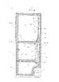
図1は、本実施形態に係る冷蔵庫1の概略構造を示す正面外観図である。図2は、冷蔵庫1の右側断面図である。なお、図2において、庫内を循環する冷気の流れを実線矢印で示している。 FIG. 1 is a front external view showing a schematic structure of the
図1に示すように、冷蔵庫1は、断熱箱体2を備え、該断熱箱体2の内部に食品等を貯蔵する貯蔵室を形成している。貯蔵室の内部は、保存温度や用途に応じて複数の収納室3〜7に区分されている。最上段が冷蔵室3、その下段左側が製氷室4で右側が上段冷凍室5、更にその下段が下段冷凍室6、最下段が野菜室7である。なお、製氷室4、上段冷凍室5及び下段冷凍室6は、何れも冷凍温度域の収納室であり、以下の説明では適宜、これらをまとめて冷凍室4〜6と称する。 As shown in FIG. 1, the
断熱箱体2の前面は開口しており、前記各収納室3〜7に対応する前記開口には、各々断熱扉8〜12が開閉自在に設けられている。断熱扉8a、8bは、冷蔵室3の前面を分割して塞ぐもので、断熱扉8aの左上下部及び断熱扉8bの右上下部が断熱箱体2に回転自在に支持されている。また、断熱扉9〜12は、冷蔵庫1の前方に引出自在に、断熱箱体2に支持されている。 The front surface of the
図2に示すように、冷蔵庫1の本体である断熱箱体2は、前面に開口部を有する鋼板製の外箱2aと、該外箱2aの内側に間隙を持たせて配設され、前面に開口部を有する合成樹脂製の内箱2bと、前記外箱2aと内箱2bとの間隙に充填発泡される発泡ポリウレタン製の断熱材2cと、から構成されている。なお、各断熱扉8〜12も、断熱箱体2と同様の断熱構造を採用している。 As shown in FIG. 2, the
冷蔵室3と、その下段に位置する冷凍室4〜6との間は、断熱仕切壁55によって仕切られている。断熱仕切壁55は、合成樹脂の成形品であり、その内部には断熱材が充填されている。 The
また、冷凍室4〜6内部の製氷室4と上段冷凍室5との間は、仕切壁(図面に表れない)によって仕切られている。製氷室4及び上段冷凍室5と、その下段に設けられる下段冷凍室6とは、冷気が流通自在に連通している。そして、冷凍室4〜6と野菜室7との間は、断熱仕切壁56によって区分けされている。 Further, the ice making chamber 4 and the upper freezing
また、冷凍室4〜6の奥側には、合成樹脂製の仕切部材で区画されて、供給風路14(冷凍室供給風路)が形成されている。供給風路14は、冷却器53で冷却された冷気を流す風路である。また、下段冷凍室6の下部背面には、冷凍室4〜6から冷却室13へと空気を戻す戻り口が形成されている。 In addition, a supply air passage 14 (freezer compartment supply air passage) is formed on the back side of the freezer compartments 4 to 6 by a partition member made of synthetic resin. The
冷蔵室3の背面には、冷却器53で冷却された冷気を冷蔵室3へと供給する風路として、供給風路15(冷蔵室供給風路)が形成されている。供給風路15は、ダクト部材30と内箱2bとの間に形成され、ダクト部材30の前面には、ダクトカバー20が配設される。 A supply air passage 15 (refrigeration chamber supply air passage) is formed on the back surface of the
供給風路14と供給風路15とは、ダンパ54(風路開閉器)を介して連通している。ダンパ54は、冷蔵室3へと供給する冷気の流量を制御して、冷蔵室3内部の温度を適切に維持するためのものである。 The
冷蔵室3と野菜室7とは、図示しない連結風路によって連通されている。これにより、冷蔵室3に供給された冷気は、連結風路を介して野菜室7へと供給される。また、断熱仕切壁56の内部には、野菜室7と冷却室13とをつなぎ、野菜室7から冷却室13へと冷気を戻すための帰還風路16が形成されている。 The
内箱2b内部の供給風路14の更に奥側には、仕切体で区分けされて冷却室13が設けられる。冷却室13上部の仕切体には、冷却室13と供給風路14とをつなぐ開口13aが形成されており、開口13aには、貯蔵室の各収納室3〜7に冷気を供給するための送風機52が配設されている。他方、冷却室13の下方には、貯蔵室からの帰還冷気を冷却室13の内部へと吸入する開口13bが形成されている。 On the further back side of the
そして、冷却室13の内部には、循環する空気を冷却するための冷却器53(蒸発器)が配置されている。冷却器53は、圧縮器51、放熱器(図示せず)、膨張弁(キャピラリーチューブ)(図示せず)に冷媒配管を介して接続されており、蒸気圧縮式の冷凍サイクル回路を構成するものである。なお、本実施形態に係る冷蔵庫1では、前記冷凍サイクルの冷媒として、イソブタン(R600a)を用いている。 A cooler 53 (evaporator) for cooling the circulating air is disposed inside the cooling
図3は、冷蔵庫1の冷蔵室3の断熱扉8を外した状態を示す正面図である。図3に示すように、冷蔵室3の略中央の奥に供給風路15の前面を覆うようにダクトカバー20が備えられる。ダクトカバー20には、冷蔵室3に冷気を吹き出す複数の吹出口21が形成される。冷却器53(図2参照)で冷却された冷気は、供給風路15を通り吹出口21より吹き出される。 FIG. 3 is a front view showing a state in which the
ダクトカバー20は、上下方向に延在する部材であり、その上部近傍及び下部近傍が、取付部材としての、ねじ39によって内箱2bに固定される。なお、ねじ39の前面には、ねじ39を前面から見えないように覆うカバー部材等が取り付けられても良い。また、ねじ39によって内箱2bに固定される固定部材等を別途設け、該固定部材にダクトカバー20を係合させて固定するよう構成することもできる。 The
図4は、冷蔵庫1の冷蔵室3の水平断面図であり、図3におけるA−A線断面を表している。図4に示すように、ダクトカバー20の背面側には、ダクト部材30が取り付けられる。即ち、ダクト部材30は、ダクトカバー20と内箱2bとに挟まれるように配設される。これにより、冷蔵室3の奥に、ダクト部材30と内箱2bとに挟まれて供給風路15が形成される。 FIG. 4 is a horizontal sectional view of the
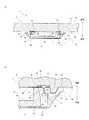
図5は、冷蔵庫1の供給風路15の概略構成を示す分解斜視図である。なお、図5において、紙面左下が冷蔵庫1の前面側である。図5に示すように、ダクト部材30は、内箱2bの内側(前面側)に取り付けられ、ダクトカバー20は、ダクト部材30を覆うようにその前面に取り付けられる。 FIG. 5 is an exploded perspective view showing a schematic configuration of the
内箱2bの背面からは、係合受部材40が挿通されて内箱2bに固定される。そして、ダクトカバー20は、係合受部材40の係合受部42に係合する。これにより、ダクトカバー20及びダクト部材30が内箱2bに固定される From the back surface of the
ここで、ダクトカバー20は、例えば、PP(ポリプロピレン)等の合成樹脂から成形される部材である。他方、ダクト部材30は、例えば、PS(発泡ポリスチレン)等から成形される部材である。なお、ダクトカバー20やダクト部材30には、各種センサや配線等を装着するための図示しない形状、例えば、凹凸形状や溝等を形成しても良い。 Here, the
ダクト部材30の左右側面部の上下方向の略中央には、ダクト部材30の中心方向に凹む凹部34が形成されている。凹部34は、内箱2bの背面から取り付けられて内箱の内側に突出する係合受部材40の係合受部42に干渉しないように形成される逃げ構造である。係合受部42と凹部34との位置が対応することにより、内箱2bに対するダクト部材30の位置決めが容易になる。 A
図6は、冷蔵庫1のダクトカバー20及びダクト部材30を示す分解斜視図である。なお、図6において、紙面左上が冷蔵庫1の前面である。図6に示すように、ダクト部材30は、水平断面略コ字状で上下方向に延在する部材である。具体的には、ダクト部材30の背面には、水平断面略コ字状で上下方向に延在する凹部32が形成されており、この凹部32が冷気を流す供給風路15となる。 FIG. 6 is an exploded perspective view showing the
前述のとおり、ダクトカバー20の前面部22には、冷蔵室3(図2参照)に冷気を送るための吹出口21が形成されている。また、ダクト部材30の前面には、供給風路15からの冷気を吹き出すための吹出孔31が形成されている。 As described above, the
ここで、ダクトカバー20の吹出口21及びダクト部材30の吹出孔31の位置は、夫々対応している。吹出口21及び吹出孔31を通して供給風路15からの冷気を冷蔵室3へと送ることができる。 Here, the positions of the
ダクトカバー20の上部近傍及び下部近傍には、ダクトカバー20を内箱2b(図5参照)に固定するための取付孔28が形成されている。即ち、ダクトカバー20は、上部近傍の取付孔28及び下部近傍の取付孔28に挿通されるねじ39(図3参照)によって、内箱2bに固定される。 An
なお、ダクト部材30の下部近傍右側には、ダクトカバー20と内箱2bとを固定するための取付孔33が形成されている。取付孔33の位置は、ダクトカバー20の下部近傍右側の取付孔28に対応しており、取付孔28、33に、ねじ39が挿通されることにより、ダクトカバー20及びダクト部材30の下部近傍右側が内箱2bに固定される。 An
また、ダクトカバー20の背面側の左右には、係合部25が形成されている。詳しくは、係合部25は、上部近傍の取付孔28よりも下方且つ下部近傍の取付孔28よりも上方に形成される。そして、ダクトカバー20は、係合部25が係合受部材40(図5参照)の係合受部42(図5参照)に係合することによっても、内箱2bに固定される。 Engaging
即ち、ダクトカバー20は、上部近傍及び下部近傍の取付孔28及び中間部の係合部25によって内箱2bに固定されることになる。これにより、ダクト部材30と内箱2bとの押し付け力を高め、供給風路15のシール性を確保することができる。また、ねじ39の個数が少なくても高いシール性を発揮できるので、部品数を減らして取り付け作業を容易にすることができる。 That is, the
ダクト部材30の左右側面部に形成される凹部34は、ダクトカバー20の係合部25に対応する位置に形成される(図8参照)。即ち、凹部34と係合部25は、略同じ高さに形成されている。これにより、係合部25とダクト部材30との干渉が避けられると共に、ダクトカバー20に対するダクト部材30の位置決めが容易になる。 The
また、ダクトカバー20の内側には、ガイド部24が形成されている。ガイド部24は、ダクトカバー20の前面部22の左右端部近傍から背面側に向かって突設され、上下方向に延在している。ガイド部24は、ダクト部材30を左右から挟み込むように形成されており、これにより、ダクト部材30の位置決めが容易になる。 A
ガイド部24の上部近傍及び下部近傍には、内側に向かって突出す固定爪24aが形成されている。他方、ダクト部材30には、背面左右端部の上部近傍及び下部近傍に爪受部35が形成されている。 In the vicinity of the upper portion and the lower portion of the
ダクトカバー20に組み付けられたダクト部材30は、固定爪24aによって支持される。即ち、固定爪24a及び爪受部35の位置は、夫々対応しており、固定爪24aを爪受部35に係合させることにより、ダクトカバー20とダクト部材30とが固定される。これにより、ダクト部材30の脱落を防止して、ダクト部材30が取り付けられたダクトカバー20を内箱2bに取り付ける作業を容易に行うことができる。 The
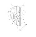
図7(A)は、冷蔵庫1の供給風路15部分を拡大した水平断面図であり、図4におけるB部の拡大図である。図7(B)は、係合部25の近傍を拡大して示す水平断面図であり、図7(A)に示すC部の拡大図である。 FIG. 7A is an enlarged horizontal sectional view of the
図7(A)に示すように、内箱2bとダクト部材30との当接部には、シール部材38が介装される。つまり、水平断面略コ字状を成すダクト部材30の背面側の端面であるシール面36は、シール部材38を介して内箱2bに当接する。シール部材38は、例えば、発砲樹脂製のシート材等である。これにより、ダクト部材30と内箱2bとの当接部のシール性を高め、供給風路15から冷気が漏れ出ることを抑制している。 As shown in FIG. 7A, a
内箱2bには、冷蔵庫1の前面側に向かって突出して、ダクト部材30の左右外側に沿って上下方向に延在する凸部45が形成されている。凸部45は、係合受部材40の左右外側に形成され、ダクト部材30を左右から挟み込むように設けられる。 The
内箱2bに凸部45を形成することにより、ダクトカバー20及びダクト部材30を内箱2bに取り付ける際、凸部45によってダクトカバー20及びダクト部材30が案内されるので、その位置決めが容易になる。 By forming the
また、凸部45によりダクトカバー20及びダクト部材30が案内されて装着が容易になることにより、係合部25に過大な力が作用することを抑制して、係合部25の破損等を防止することができる。 In addition, the
また、ダクトカバー20及びダクト部材30が装着された後は、凸部45によってダクトカバー20の係合部25の過大な変位が規制されるので、係合部25と係合受部42との係合の外れを防止することができる。また、凸部45は、アンダーカット形状ではないので、内箱の加工が容易である。 In addition, after the
図7(B)に示すように、係合受部材40は、基部41と、基部41から突設される係合受部42と、を有し、内箱2bの背面側から取り付けられる。詳しくは、係合受部42は、内箱2bに形成される取付孔46に挿通されて内箱2bの内側に突き出される。 As shown in FIG. 7B, the
係合受部材40の基部41は内箱2bの背面側に当接し、背面側から図示しないテープ等で固定される。また更に、基部41は、断熱箱体2を組み立てる際に断熱箱体2の内部に発泡充填される断熱材2cによって固定される。 The
前述のとおり、ダクトカバー20の係合部25は、係合受部材40の係合受部42に係合する。これにより、ダクトカバー20が内箱2bに固定される。詳しくは、ダクトカバー20の係合部25には、左右方向の内側に向かって突設される爪部26が設けられており、内箱2bの内側に突き出される係合受部42には、左右方向の外側に向かって突設される突起部43が形成されている。 As described above, the engaging
なお、突起部43は、係合受部42の側面略中央に凹部を形成して係合受部42の先端近傍を相対的に厚くすることよって形成されても良い。また、係合受部42の側面略中央に凹部を形成して突起部43を形成することにより、係合受部42の上下端部近傍を突起部43と同程度の厚みに形成しても良い。これにより、係合受部材40の軽量化を図りつつ、係合受部42の強度を確保することができる。 Note that the protrusion 43 may be formed by forming a recess substantially in the center of the side surface of the
そして、係合部25の爪部26が係合受部42の突起部43に引っ掛かることによりダクトカバー20と内箱2bとが固定される。これにより、ダクト部材30は、ダクトカバー20によって内箱2b側へ押圧される。即ち、ダクト部材30は、ダクトカバー20により全体的に圧力を受けて、内箱2bに押し付けられる。その結果、ダクト部材30のシール面36と内箱2bとの間に間隙が生ずることが抑制され、供給風路15のシール性が向上する。 And the
また、係合部25及び係合受部材40は、ダクト部材30の左右に設けられる。そのため、ダクト部材30の左右両側でダクト部材30と内箱2bとの押し付け力が高められ、これにより、高いシール性が発揮される。 Further, the engaging
また、係合部25は、左右方向の内側に向かって突設される爪部26を有し、係合受部材42に対して左右方向の外側から係合するので、ダクトカバー20の側面部23近傍を外側へ拡げることにより、係合部25と係合受部42との係合を容易に解除することがきる。即ち、ダクトカバー20及びダクト部材30を容易に取り外すことができる。また、ダクトカバー20を取り外す際、ダクトカバー20の係合部25や爪部26に過大な力が作用しないので、係合部25や爪部26が破損しにくい。 Further, since the engaging
また、前述のとおり、ダクトカバー20は、例えば、PP等の合成樹脂から形成されており、このダクトカバー20に係合部25が形成されている。これにより、PS等で成形されるダクト部材30に係合部を形成する場合に比べ、係合部25の強度を高く確保することができる。これにより、ダクト部材30と内箱2bとの押し付け力を高めてシール性を向上させると共に、取り付けや取り外し時の係合部25の破損等を抑制することができる。 Further, as described above, the
ダクトカバー20の側面部23は、前面部22の左右両端部から連続して斜め背面側に折れ曲がるよう延設される。これにより、内箱2bの凸部45、係合部25、係合受部材40及びダクト部材30等を隠すことができ、意匠性が向上する。 The
また、ダクトカバー20の左右両端部と内箱2bとの間には、僅かな間隙47を設けている。つまり、ダクトカバー20の側面部23の端部は、内箱2bに当接していない。間隙47を設けることにより、ダクトカバー20を取り外す際、間隙47に指先(爪先)若しくは工具等を差し込むことができる。これにより、ダクトカバー20の取り外しが容易になる。 A
また、ダクトカバー20の左右外側には、ダクトカバー20の側面部23端部近傍が左右外側へ弾性変形することを許容する空間部48を確保している。即ち、ダクトカバー20の左右外側には、ダクトカバー20と干渉する形状を形成しない。 Further, on the left and right outer sides of the
これにより、ダクトカバー20の取り外し時に、ダクトカバー20の側面部23を左右に拡げ易くなる。また、空間部48形成することにより、作業者は、ダクトカバー20を掴み易くなり、指先(爪先)や工具等を間隙47に差し込む作業も容易に行うことができる。 Thereby, when the
また、係合部25と凸部45との間には、係合部25が左右外側へ弾性変形することを許容する空間部49が確保されている。これにより、ダクトカバー20の取り付け及び取り外し作業が容易になる。 Further, a
即ち、ダクトカバー20の取り付け時及び取り外し時には、係合部25は、凸部45によって案内されつつ、空間部49によって、係合受部42との係脱が可能な程度に外側へと拡がるよう変形することができる。これにより、ダクトカバー20を容易に取り付ける若しくは取り外すことができる。 That is, when the
図8は、冷蔵庫1の係合部25の近傍を示す拡大斜視図である。なお、図8は、ダクトカバー20にダクト部材30が取り付けられた状態を示し、図8において、紙面右上が冷蔵庫1の前面側である。 FIG. 8 is an enlarged perspective view showing the vicinity of the engaging
図8に示すように、係合部25は、ガイド部24に形成されており、係合部25の上下近傍のガイド部24には、略V形状の切欠部29が形成されている。これにより、係合部25は、ガイド部24から独立して弾性変形し易くなり、ダクトカバー20の取り付け及び取り外しが容易になる。 As shown in FIG. 8, the engaging
また、係合部25をガイド部24に形成することにより、係合部25をガイド部24とは別途独立して形成する場合に比べ、ダクトカバー20の成形が容易になる。 In addition, by forming the engaging
ダクトカバー20には、側面部23とガイド部24との間をつなぐ補強リブ27が複数形成される。特に、係合部25の近傍に形成される補強リブ27は、係合部25の強度を高め、係合部25と係合受部42(図7参照)との係合力を高め、係合部25の外れを抑制する効果を持つ。 The
図9は、冷蔵庫1の内箱2b及び係合受部材40を示す背面分解斜視図である。なお、図9において、紙面左上が冷蔵庫1の前面側である。図9に示すように、内箱2bは、例えば、ABS樹脂(アクリロニトリル、ブタジエン、スチレン共重合樹脂)で形成され、内箱2bには、係合受部材40を取り付けるための取付孔46が形成される。取付孔46は、打ち抜き孔であり、その加工は、容易である。 FIG. 9 is a rear exploded perspective view showing the
前述のとおり、係合受部材40は、内箱2bの背面に当接する基部41と、基部41から前方に向かって略垂直に立設される係合受部42と、係合受部42に形成されてダクトカバー20の係合部25(図8参照)を係合させるための突起部43(図7参照)と、を有する。 As described above, the
基部41は、係合受部材40を内箱2bの背面に固定するための部分であり、内箱b2の背面に当接する略矩形板状の形態を成す。基部41は、内箱2bの取付孔46より大きく、係合受部材40を内箱2bに取り付けた際に、留め具としての役割を果たす。 The
基部41から突設される係合受部42は、内箱2bの取付孔46に背面側から挿入されて、内箱2bの内側に配置される。そして、係合受部材40の基部41は、内箱の背面側からテープ等で仮固定される。内箱2bと外箱2a(図4参照)を組み立て、内箱2bと外箱2aとの間に断熱材2c(図4参照)としてのポリウレタンが発泡される。これにより、係合受部材40が強固に固定される。 The
以上、本発明の実施形態に係る冷蔵庫について説明したが、本発明は、これに限定されるものではなく、本発明の要旨を逸脱しない範囲で、種々の変更が可能である。 As mentioned above, although the refrigerator which concerns on embodiment of this invention was demonstrated, this invention is not limited to this, A various change is possible in the range which does not deviate from the summary of this invention.
1 冷蔵庫
2 断熱箱体
2a 外箱
2b 内箱
2c 断熱材
3 冷蔵室
15 供給風路
20 ダクトカバー
24 ガイド部
25 係合部
26 爪部
30 ダクト部材
40 係合受部材
41 基部
42 係合受部
43 突起部
45 凸部
46 取付孔
47 間隙
48 空間部
49 空間部DESCRIPTION OF
Claims (7)
Translated fromJapanese前記内箱の前面に設けられて前記内箱との間に風路を形成するダクト部材と、
前記ダクト部材の前面に設けられて前記ダクト部材を覆うダクトカバーと、
前記内箱に固定されて前記ダクトカバーが係合される係合受部材と、を備え、
前記内箱には、前記ダクト部材の左右外側に前記係合受部材を取り付ける取付孔が形成され、
前記係合受部材は、前記内箱の背面に当接する基部と、前記基部から前方に突設されて前記取付孔に挿通される係合受部と、前記係合受部から左右方向の外側に向かって突設される突起部と、を有し、
前記ダクトカバーには、その左右に係合部が形成され、
前記係合部は、左右方向の内側に向かって突設される爪部を有し、前記係合受部材に対して左右方向の外側から係合することを特徴とする冷蔵庫。A heat-insulating box body filled with a heat insulating material between the outer box and the inner box and opened at the front;
A duct member provided on the front surface of the inner box to form an air path between the inner box;
A duct cover provided on the front surface of the duct member and covering the duct member;
An engagement receiving member fixed to the inner box and engaged with the duct cover,
The inner box is formed with mounting holes for attaching the engagement receiving members to the left and right outer sides of the duct member,
The engagement receiving member includes a base that abuts on the back surface of the inner box, an engagement receiving part that protrudes forward from the base and is inserted into the mounting hole, and an outer side in the left-right direction from the engagement receiving part. And a projecting portion projecting toward the
The duct cover is formed with engaging portions on the left and right sides thereof,
The said engaging part has a nail | claw part protrudingly provided toward the inner side of the left-right direction, and is engaged with the said engagement receiving member from the outer side of the left-right direction.
前記係合部は、前記ガイド部に形成されることを特徴とする請求項1ないし請求項3の何れか1項に記載の冷蔵庫。The duct cover is formed with a guide portion protruding rearward and extending in the vertical direction along the left and right outer sides of the duct member,
The refrigerator according to any one of claims 1 to 3, wherein the engaging portion is formed in the guide portion.
前記ダクトカバーは、その上部及び下部において前記取付部材によって前記内箱に固定され、
前記係合部は、前記上部の取付部材よりも下方且つ前記下部の取付部材よりも上方に形成されることを特徴とする請求項1ないし請求項4の何れか1項に記載の冷蔵庫。An attachment member for fixing the duct cover and the inner box;
The duct cover is fixed to the inner box by the mounting member at an upper part and a lower part thereof,
The refrigerator according to any one of claims 1 to 4, wherein the engagement portion is formed below the upper attachment member and above the lower attachment member.
Priority Applications (1)
| Application Number | Priority Date | Filing Date | Title |
|---|---|---|---|
| JP2014256891AJP2016118313A (en) | 2014-12-19 | 2014-12-19 | refrigerator |
Applications Claiming Priority (1)
| Application Number | Priority Date | Filing Date | Title |
|---|---|---|---|
| JP2014256891AJP2016118313A (en) | 2014-12-19 | 2014-12-19 | refrigerator |
Publications (1)
| Publication Number | Publication Date |
|---|---|
| JP2016118313Atrue JP2016118313A (en) | 2016-06-30 |
Family
ID=56243983
Family Applications (1)
| Application Number | Title | Priority Date | Filing Date |
|---|---|---|---|
| JP2014256891APendingJP2016118313A (en) | 2014-12-19 | 2014-12-19 | refrigerator |
Country Status (1)
| Country | Link |
|---|---|
| JP (1) | JP2016118313A (en) |
Cited By (4)
| Publication number | Priority date | Publication date | Assignee | Title |
|---|---|---|---|---|
| JP2018138859A (en)* | 2017-02-24 | 2018-09-06 | ホシザキ株式会社 | refrigerator |
| JPWO2021024291A1 (en)* | 2019-08-02 | 2021-02-11 | ||
| JP2021509944A (en)* | 2018-11-28 | 2021-04-08 | 合肥美的電冰箱有限公司Hefei Midea Refrigerator Co.,Ltd. | refrigerator |
| JP7592457B2 (en) | 2020-10-27 | 2024-12-02 | 東芝ライフスタイル株式会社 | refrigerator |
- 2014
- 2014-12-19JPJP2014256891Apatent/JP2016118313A/enactivePending
Cited By (5)
| Publication number | Priority date | Publication date | Assignee | Title |
|---|---|---|---|---|
| JP2018138859A (en)* | 2017-02-24 | 2018-09-06 | ホシザキ株式会社 | refrigerator |
| JP2021509944A (en)* | 2018-11-28 | 2021-04-08 | 合肥美的電冰箱有限公司Hefei Midea Refrigerator Co.,Ltd. | refrigerator |
| JPWO2021024291A1 (en)* | 2019-08-02 | 2021-02-11 | ||
| JP7301137B2 (en) | 2019-08-02 | 2023-06-30 | 三菱電機株式会社 | refrigerator |
| JP7592457B2 (en) | 2020-10-27 | 2024-12-02 | 東芝ライフスタイル株式会社 | refrigerator |
Similar Documents
| Publication | Publication Date | Title |
|---|---|---|
| US9816747B2 (en) | Refrigerator and manufacturing method thereof | |
| US10047994B2 (en) | Refrigerator and method for assembling ice machine thereof | |
| KR20170065775A (en) | Refrigerator | |
| JP2016118313A (en) | refrigerator | |
| JP2010060187A (en) | Refrigerator | |
| JP4093973B2 (en) | refrigerator | |
| US12352490B2 (en) | Refrigerator | |
| WO2014112333A1 (en) | Refrigerator | |
| JP7456854B2 (en) | refrigerator | |
| WO2016208189A1 (en) | Refrigerator | |
| CN116324316A (en) | refrigerator | |
| JPH1194436A (en) | refrigerator | |
| JP2013057470A (en) | Refrigerator | |
| CN107636409B (en) | Refrigerator with a door | |
| JP6386274B2 (en) | refrigerator | |
| JP6681781B2 (en) | Cold storage | |
| JP6803530B2 (en) | refrigerator | |
| KR101728731B1 (en) | Refrigerator | |
| US12410966B2 (en) | Plate assembly and home appliance | |
| KR20230038047A (en) | Refrigerator | |
| EP4549856A1 (en) | Refrigerator | |
| JP2016075421A (en) | refrigerator | |
| CN120212680A (en) | refrigerator | |
| JP6490956B2 (en) | refrigerator | |
| JP2024042298A (en) | refrigerator |