JP2016111595A - Image processor, control method thereof, and program - Google Patents
Image processor, control method thereof, and programDownload PDFInfo
- Publication number
- JP2016111595A JP2016111595AJP2014248835AJP2014248835AJP2016111595AJP 2016111595 AJP2016111595 AJP 2016111595AJP 2014248835 AJP2014248835 AJP 2014248835AJP 2014248835 AJP2014248835 AJP 2014248835AJP 2016111595 AJP2016111595 AJP 2016111595A
- Authority
- JP
- Japan
- Prior art keywords
- image processing
- mfp
- information
- access
- setting
- Prior art date
- Legal status (The legal status is an assumption and is not a legal conclusion. Google has not performed a legal analysis and makes no representation as to the accuracy of the status listed.)
- Granted
Links
Images


Landscapes
- Accessory Devices And Overall Control Thereof (AREA)
- Facsimiles In General (AREA)
Abstract
Translated fromJapaneseDescription
Translated fromJapanese本開示は、画像処理装置、その制御方法、およびプログラムに関し、特に、通信先を当該通信先からの通信経路に基づいて制限する画像処理装置、その制御方法、およびそのような画像処理装置において実行されるプログラムに関する。 The present disclosure relates to an image processing device, a control method thereof, and a program, and in particular, an image processing device that restricts a communication destination based on a communication path from the communication destination, a control method thereof, and such an image processing device. Related to the program.
近年、ネットワーク上で使用される画像処理装置において、ネットワーク管理者が、セキュリティ強度を高めるために、通信相手を制限する場合がある。たとえば、特開2005−086580号公報(特許文献1)には、外部機器(PC(パーソナルコンピューター)端末、複合機、等)のネットワークアドレスを画像処理装置に事前に登録しておき、外部から受信したアドレスが上記のように事前に登録されたアドレスと一致した場合には指示された処理を禁止する等の技術が開示されている。 In recent years, in an image processing apparatus used on a network, a network administrator sometimes restricts communication partners in order to increase security strength. For example, in Japanese Patent Application Laid-Open No. 2005-086580 (Patent Document 1), a network address of an external device (PC (personal computer) terminal, multifunction device, etc.) is registered in advance in an image processing apparatus and received from the outside. A technique has been disclosed such as prohibiting the instructed processing when the address matches the address registered in advance as described above.
一般的なネットワークシステムでは、通信相手を制限するために、建物ごとや部署ごとに通信相手が制限されるように、IP(インターネットプロトコル)アドレスについてのフィルターが設定される。以下、IPアドレスについてフィルターを設定することを適宜「IPフィルタリング」という。 In a general network system, a filter for an IP (Internet Protocol) address is set so that a communication partner is restricted for each building or department in order to restrict the communication partner. Hereinafter, setting a filter for an IP address is appropriately referred to as “IP filtering”.
上記のようなIPフィルタリングでは、場合によっては実質的な使用環境が考慮されることなく、行なわれる場合がある。たとえば、部署の体制変更によって新たなIPフィルタリングが設定されることにより、あるPC端末から、物理的には近くに位置するが、異なる部署の所属となってしまった画像処理装置に対して印刷指示を送ることができなくなる場合があり得る。 In some cases, the IP filtering as described above is performed without considering a substantial use environment. For example, when a new IP filtering is set by changing the department system, a print instruction is given to an image processing apparatus that is physically close to a PC terminal but belongs to a different department. May not be able to be sent.
本開示は、かかる実情を鑑み考え出されたものであり、その目的は、画像処理装置において、外部機器からのアクセスを制限することによりセキュリティ強度を確保しつつ、必要な機器からのアクセスは許容できるようにすることである。 The present disclosure has been devised in view of such circumstances, and the purpose of the present disclosure is to allow access from necessary devices while ensuring security strength by restricting access from external devices in the image processing apparatus. Is to be able to do it.
ある局面に従うと、アクセスを禁止するアドレスについてのフィルターの設定の変更を検出するための設定変更検出手段と、フィルターの設定の変更前にアクセスが可能な機器について、当該機器のアドレスを含む情報を記憶するための機器情報記憶手段と、機器情報記憶手段に記憶された機器のうち、設定変更検出手段によって検出された変更後のフィルターによってアクセスを禁止される機器を特定するための特定手段と、特定手段によって特定された機器の中の少なくとも一部の機器についてアクセスを許可するための情報を設定するための許可情報設定手段とを備える、画像処理装置が提供される。 According to a certain aspect, setting change detection means for detecting a change in the filter setting for an address for which access is prohibited, and information including the address of the device about the accessible device before the filter setting is changed. A device information storage means for storing; a device for specifying a device whose access is prohibited by the changed filter detected by the setting change detection device among the devices stored in the device information storage device; An image processing apparatus is provided that includes permission information setting means for setting information for permitting access to at least some of the devices specified by the specifying means.
好ましくは、機器情報記憶手段は、フィルターの設定の変更前にアクセスを受けた機器についての履歴であって各機器のアドレスを含む履歴を記憶する。 Preferably, the device information storage unit stores a history of devices that have been accessed before the filter setting is changed, and includes a history including addresses of the devices.
好ましくは、画像処理装置は、画像処理装置と他の機器とを関連付けるための情報を記憶するための関連情報記憶手段をさらに備え、許可情報設定手段は、特定手段によって特定された機器の中の、関連情報記憶手段に記憶された情報によって画像処理装置と関連付けられる機器について、アクセスを許可するための情報を設定する。 Preferably, the image processing apparatus further includes related information storage means for storing information for associating the image processing apparatus with other equipment, and the permission information setting means is included in the equipment specified by the specifying means. Then, information for permitting access is set for the device associated with the image processing apparatus by the information stored in the related information storage means.
好ましくは、関連情報記憶手段によって記憶される情報は、画像形成装置が受信した画像データの出力先として指定された機器であって、当該機器においてユーザー認証により当該画像データが出力された機器を特定する情報を含む。 Preferably, the information stored by the related information storage unit is a device designated as an output destination of the image data received by the image forming apparatus, and specifies the device to which the image data is output by user authentication in the device. Information to be included.
好ましくは、画像処理装置は、画像処理装置が通信可能な機器であって、設定変更検出手段によって検出されたフィルターの設定によってはアクセスを禁止されない機器の中から、アクセスを禁止する機器を選択し、当該アクセスを禁止する情報を設定するための、アクセス禁止設定手段をさらに備える。 Preferably, the image processing apparatus selects a device that prohibits access from devices that can communicate with the image processing device and that is not permitted to access depending on the filter setting detected by the setting change detection unit. And an access prohibition setting means for setting information prohibiting the access.
好ましくは、画像処理装置は、アクセスを受けたユーザーの履歴を記憶するためのユーザー情報記憶手段をさらに備え、許可情報設定手段は、ユーザー情報記憶手段に記憶されたユーザーを特定する情報に関連付けられた機器を特定する情報を取得し、当該取得した情報によって特定される機器についてアクセスを許可する。 Preferably, the image processing apparatus further includes user information storage means for storing a history of users who have been accessed, and the permission information setting means is associated with information specifying the user stored in the user information storage means. Information for identifying the acquired device is acquired, and access is permitted for the device specified by the acquired information.
好ましくは、関連情報記憶手段によって関連付けられる他の機器は、画像処理装置が記憶装置を互いに連携させた他の画像処理装置である。 Preferably, the other device associated by the related information storage unit is another image processing device in which the image processing device causes the storage devices to cooperate with each other.
好ましくは、関連情報記憶手段によって関連付けられる他の機器は、画像処理装置と省電力機能に関し連携して動作する他の画像処理装置である。 Preferably, the other device associated by the related information storage unit is another image processing device that operates in cooperation with the image processing device with respect to the power saving function.
他の局面に従うと、アクセスを制限可能な画像処理装置の制御方法であって、アクセスを禁止するアドレスについてのフィルターの設定の変更を検出するステップを備え、画像処理装置は、フィルターの設定の変更前にアクセスが可能な機器について、当該機器のアドレスを含む情報を記憶する機器情報記憶手段を備え、制御方法は、さらに、機器情報記憶手段に記憶された機器のうち、検出された変更後のフィルターによってアクセスを禁止される機器を特定するステップと、特定された機器の中の少なくとも一部の機器についてアクセスを許可するための情報を設定するステップとを含む、画像処理装置の制御方法が提供される。 According to another aspect, there is provided a method of controlling an image processing apparatus capable of restricting access, comprising a step of detecting a change in a filter setting for an address for which access is prohibited, and the image processing apparatus includes a change in the filter setting. A device information storage unit that stores information including an address of the device with respect to a device that can be accessed in advance, and the control method further includes a detected changed device among the devices stored in the device information storage unit. Provided is a method for controlling an image processing apparatus, the method comprising: identifying a device whose access is prohibited by a filter; and setting information for permitting access to at least some of the identified devices. Is done.
さらに他の局面に従うと、アクセスを制限可能な画像処理装置のコンピューターによって実行されるプログラムが提供される。プログラムは、コンピューターに、アクセスを禁止するアドレスについてのフィルターの設定の変更を検出するステップを実行させ、画像処理装置は、フィルターの設定の変更前にアクセスが可能な機器について、当該機器のアドレスを含む情報を記憶する機器情報記憶手段を備え、プログラムは、コンピューターに、さらに、アクセスを禁止するアドレスについてのフィルターの設定の変更を検出するステップと、機器情報記憶手段に記憶された機器のうち、検出された変更後のフィルターによってアクセスを禁止される機器を特定するステップと、特定された機器の中の少なくとも一部の機器についてアクセスを許可するための情報を設定するステップとを実行させる。 According to yet another aspect, a program executed by a computer of an image processing apparatus capable of restricting access is provided. The program causes the computer to execute a step of detecting a change in the filter setting for an address for which access is prohibited, and the image processing apparatus sets an address of the device for an accessible device before the change of the filter setting. Device information storage means for storing information including, the program further detects the change of the filter setting for the address for which access is prohibited, and among the devices stored in the device information storage means, A step of specifying a device whose access is prohibited by the detected changed filter and a step of setting information for permitting access to at least some of the specified devices are executed.
以下に、図面を参照しつつ、画像処理装置の実施の形態について説明する。以下の説明では、同一の部品および構成要素には同一の符号を付してある。それらの名称および機能も同じである。したがって、これらの説明は繰り返さない。 Hereinafter, an embodiment of an image processing apparatus will be described with reference to the drawings. In the following description, the same parts and components are denoted by the same reference numerals. Their names and functions are also the same. Therefore, these descriptions will not be repeated.
[画像処理システムの概略構成]
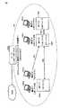
図1は、本開示に係る画像処理システムの概略的な構成の一例を示す図である。画像処理システムは、画像処理装置の一例であるMFP100と、情報処理装置の一例として端末200とを含む。本明細書では、複数台のMFP100を互いに区別するために、適宜「MFP100A」「MFP100B」等のような記述が用いられることがある。また、複数台の端末200を互いに区別するために、適宜「端末200A」「端末200B」等のような記述が用いられることがある。図1に示されるように、画像処理システムは、3台のMFP100A〜100Cを含む。3台のMFP100A〜100Cのうち、MFP100Bはサーバーとして機能する。また、図1には、情報処理装置の一例として端末200Aが示されている。[Schematic configuration of image processing system]
FIG. 1 is a diagram illustrating an example of a schematic configuration of an image processing system according to the present disclosure. The image processing system includes an
図1の画像処理システムにおいて、端末200Aは、たとえば当該端末200Aにインストールされている画像出力用アプリケーションを利用して、MFP100Bにプリントジョブを送信する。これに応じて、MFP100Bは、3台のMFP100A〜100Cのうちジョブの実行に適したMFP100を検索する。そして、MFP100Bは、たとえば、MFP100Aを、当該ジョブの実行に適していると判断する。そして、MFP100Bは、端末200Aから送信されたジョブを送信(スプール)する。 In the image processing system of FIG. 1,
[画像処理システムにおける処理の概略]
ネットワーク構成が変更されることによって、変更前には許可されていた機器間の通信が禁止される場合がある。本実施の形態の画像処理システムのMFP100は、ネットワーク構成の変更によって通信を禁止され得る機器がある場合、そのような機器を特定する。そして、MFP100は、そのように特定された機器の中の少なくとも一部を、当該通信の禁止の対象から除外するための情報を設定する。これにより、MFP100は、当該設定の対象となった機器との通信を禁止されない。したがって、MFP100は、当該設定の対象となった機器との通信を継続できる。[Outline of processing in image processing system]
When the network configuration is changed, communication between devices that were permitted before the change may be prohibited.
たとえば、図1に示された画像処理システムにおいて、ネットワーク構成の変更によってMFP100Bが端末200Aとの通信が禁止される場合を想定する。このような場合に、MFP100Bにおいて、端末200Aを通信の禁止の対象から除外するための情報が登録される。これにより、上記のようにネットワークが変更された後でも、MFP100Bは、端末200Aと継続して通信することができ、これにより、端末200Aから送信されるジョブを受け付けることができる。 For example, in the image processing system shown in FIG. 1, it is assumed that
これにより、たとえば、画像処理システム内のネットワーク構成が、当該画像処理システムにおける機器間の通信の実情とは無関係に変更された場合であっても、必要な通信は継続され得る。 Thereby, for example, even when the network configuration in the image processing system is changed regardless of the actual state of communication between devices in the image processing system, necessary communication can be continued.
[画像処理システムにおけるネットワーク構成の変更時の処理の概要]
図2〜図4は、画像処理システムにおける処理の概略を説明するための図である。[Overview of processing when changing the network configuration in an image processing system]
2 to 4 are diagrams for explaining an outline of processing in the image processing system.
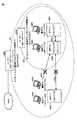
まず図2を参照して、画像処理システムは、3台のMFP100A〜100Cと、4台の端末200A〜200Dと、ルーター300Aとを含む。MFP100A〜100Cおよび端末200A〜200Dによって、ネットワーク301が構成されている。ネットワーク301は、ルーター300Aを介して、WAN(Wide Area Network)に接続されている。 Referring first to FIG. 2, the image processing system includes three
MFP100Bは、ネットワーク301内のサーバーとして機能する。本実施の形態では、ルーター300Aは、MFP100Bが備えるルーター機能によって実現される。ネットワーク301内のネットワーク設定を、表1に示す。

表1には、各装置のIPアドレスとともに、ネットワーク301のルーター300Aにおけるサブネットマスク(255.255.248.0)が示されている。 Table 1 shows the subnet mask (255.255.248.0) in the
図2の画像処理システムでは、3台のMFP100A〜100Cおよび4台の端末200A〜200Dのそれぞれが互いに通信可能である。たとえば、経路R01で示されるように、端末200Aは、MFP100Bに、ジョブを送信する。これに応じて、MFP100Bは、ネットワーク301内で当該ジョブの実行に適したMFP100を検索する。 In the image processing system of FIG. 2, each of the three
ジョブの実行に適していることの一例は、たとえば、その時点で負荷が軽い(たとえば、ジョブ実行中ではない、予約されているジョブの数が少ない、等)ことである。また、他の例は、MFPの設置場所が、当該ジョブの送信元である端末200Aからの距離が最も近いことである。さらに他の例は、当該ジョブの送信を指示したユーザーに対して設定された条件(たとえば、当該ユーザーが所属する部署に対して使用を許可されていること)を満たすことである。 An example of being suitable for job execution is, for example, that the load is light at that time (for example, the job is not being executed, the number of reserved jobs is small, etc.). Another example is that the installation location of the MFP is closest to the terminal 200A that is the transmission source of the job. Yet another example is to satisfy a condition set for a user who has instructed transmission of the job (for example, use is permitted for a department to which the user belongs).
MFP100Bは、検索結果として、たとえばMFP100Aを選択する。そして、MFP100Bは、選択結果であるMFP100Aに、経路R02で示されるように、端末200Aから受信したジョブを送信する。これにより、MFP100Aは、当該ジョブを受信し、そして、当該ジョブを実行する。 For example,
なお、MFP100Bは、当該MFP100Bが上記ジョブの実行に適していると判断すると、上記ジョブを実行する。また、MFP100Bは、MFP100Cが上記ジョブの実行に適していると判断すると、経路R03で示されるように、上記ジョブをMFP100Cへ送信する。これにより、MFP100Cが、上記ジョブを実行する。 When
図3には、図2に示された画像処理システムにおいてネットワーク構成が変更されたときの通信態様が示されている。図3の画像処理システムでは、ネットワーク301内に、ネットワーク302が設定されている。ネットワーク302は、MFP100B、MFP100C、端末200C、端末200D、およびルーター300Bを含む。本実施の形態において、ルーター300Bは、MFP100Bが備えるルーター機能として実現される。図3のネットワーク301における設定を表2に示す。 FIG. 3 shows a communication mode when the network configuration is changed in the image processing system shown in FIG. In the image processing system of FIG. 3, a
表2に示されるように、図3の画像処理システムでは、ネットワーク301内にネットワーク302が形成されている。そして、表2では、各機器のIPアドレスとともに、ネットワーク302のルーター300Bのサブネットマスク(255.255.252.0)が示されている。 As shown in Table 2, in the image processing system of FIG. 3, a
ルーター300Aのサブネットマスク(255.255.248.0)が1クラスあたり2048個(クラスCで8個分)のIPアドレスの割り振りが可能なのに対し、ルーター300Bのサブネットマスク(255.255.252.0)の1クラスあたりで割り振りが可能なIPアドレスは、1024個(クラスCで4個分)である。つまり、ルーター300Bが設置されることにより、ネットワーク301内の機器であってネットワーク302外の機器が、IPフィルタリングによって、ネットワーク302内の機器にアクセスできなくなるケースが生じ得る。 The
図3では、ルーター300Bにより、経路R01と経路R02が遮断されている状態が示されている。つまり、図3では、ネットワーク302の外にある端末200AおよびMFP100Aが、ネットワーク302内のMFP100Bにアクセスできなくなっている状態が示されている。 FIG. 3 shows a state where the route R01 and the route R02 are blocked by the
しかしながら、本実施の形態では、ルーター300Bが設置されることによってMFP100Bにアクセスできなくなる機器が存在する場合、MFP100Bは、そのような機器を特定する。そして、MFP100Bでは、たとえばそのような機器のリストが表示される。そして、当該リストから、MFP100Bのユーザー(または、ネットワーク302の管理者)は、MFP100Bへのアクセスの禁止を解除する機器を選択する。これにより、MFP100Bでは、選択された機器を特定する情報が設定される。これにより、MFP100Bは、設定された機器からのアクセスが禁止されない。つまり、MFP100Bと選択された機器との通信が継続される。 However, in this embodiment, when there is a device that cannot access
図4には、図3に示された状態から、MFP100Bにおいて、「フィルタリング除外IP」として、端末200AおよびMFP100Aのアクセスの禁止を解除する情報(端末200AのIPアドレス(150.17.3.101)およびMFP100AのIPアドレス(150.17.3.10)が設定されている。これにより、ルーター300Bが設置されていても、MFP100BおよびMFP100AからのMFP100Bへのアクセスが禁止されない。つまり、経路R01および経路R02は、遮断されない。 In FIG. 4, from the state shown in FIG. 3, in
[ハードウェア構成]
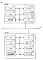
図5は、第1の実施の形態の画像処理システムのMFP100および端末200の構成を示す図である。図5では、1台のMFP100と1台の端末200のみが示されているが、画像処理システムに含まれるMFP100および端末200のそれぞれの数はこれに限定されない。本実施の形態では、端末200の一例は、スマートフォンである。なお、本実施の形態の情報処理装置はこれに限定されない。情報処理装置は、通信機能を有する装置であれば、汎用のコンピューターやタブレット端末等の他の装置であってもよい。[Hardware configuration]
FIG. 5 is a diagram illustrating configurations of the
図5に示されるように、MFP100は、端末200と、ネットワーク(図5中のLAN(Local Area Network))を介して通信する。図5中のLANは、たとえば、図2に示されるネットワーク301や図3に示されるネットワーク301,302である。以下に、MFP100と端末200のそれぞれについて、ハードウェア構成を説明する。 As shown in FIG. 5,
(MFP100)
図5に示されるように、MFP100は、主な構成要素として、CPU(Central Processing Unit)101と、ROM(Read Only Memory)102と、RAM(Random Access Memory)103と、補助記憶装置104と、NIC(Network Interface Card)106と、操作パネル107と、スキャナー部108と、プリンター部109とを備えている。CPU101と、ROM102と、RAM103と、補助記憶装置104と、NIC106と、操作パネル107と、スキャナー部108と、プリンター部109とは、互いに内部バスで接続されている。(MFP100)
As shown in FIG. 5, the
CPU101は、MFP100の動作を統括的に制御するための処理を実行するプロセッサーの一例である。
ROM102は、CPU101が実行するプログラムを含む各種のデータを格納する。
RAM103は、CPU101におけるプログラム実行時のワークエリアとして機能する。RAM103は、スキャナー部108で読み取られた画像データ等を一時的に保存する場合もある。The
The
補助記憶装置104は、MFP100に登録されている宛先情報やドキュメントなどの各種のデータを保存する。ドキュメントのデータは、ネットワークを介してMFP100に入力される場合もあれば、スキャナー部108で画像が読み取られることによって生成される場合もある。補助記憶装置104は、また、端末200から送信された設定値を格納する。これにより、端末200のウェブブラウザーに入力された設定値によって規定される設定内容がMFP100に反映され得る。 The
操作パネル107は、コピーの画質または用紙のための設定値、スキャンの送信先(宛先登録)を登録または選択するための情報など、各種の情報の入力を受け付ける。操作パネル107の表面には、たとえばタッチパネルが積層された液晶表示部が設けられている。操作パネル107は、たとえばMFP100における設定内容を表示する。 The
スキャナー部108は、セットされた原稿をスキャンし、原稿の画像データを生成する。スキャナー部108における画像データの生成方法は公知の方法を採用することができるため、ここでは詳細な説明は繰り返さない。 The
プリンター部109は、たとえば電子写真方式により、スキャナー部108で読み取られた画像データや、端末200等の外部の情報処理装置から送信されたプリントデータを、印刷のためのデータに変換し、変換後のデータに基づいて文書等の画像を印刷する装置である。電子写真方式などの画像形成の態様は、公知の技術を採用することができるため、ここでは詳細な説明は繰り返さない。 The
MFP100において、CPU101は、サーバープログラムを実行することによってウェブサーバー150として機能する。また、CPU101は、予め定められたプログラムを実行することにより、ウェブサーバー150としての機能とは別に、MFP100自体の動作を制御する。この観点では、CPU101は、MFP100における制御手段として機能する。制御手段としてのCPU101は、スキャナー部108およびプリンター部109等のMFP100内の種々の要素の状態を検出し得る。そして、CPU101は、たとえば、スキャナー部108およびプリンター部109がジョブの実行中であるか、プリンター部109において紙詰まりが発生していないか、操作パネル107においてユーザーがネットワークシステムに管理者としてログインしているか、等を検出し、これにより、MFP100が新たな設定値を設定できない状態であるか否かを判断する。 In
(端末200)
端末200は、主な構成要素として、CPU201と、RAM202と、記憶装置203と、ディスプレイ204と、キーボード/マウス205と、NIC206とを備えている。CPU201と、RAM202と、記憶装置203と、ディスプレイ204と、キーボード/マウス205と、NIC206とは、互いに内部バスで接続されている。(Terminal 200)
The terminal 200 includes a
CPU201は、端末200の全体的な動作を制御するための処理を実行する演算装置の一例である。 The
RAM202は、CPU201における処理実行時のワークエリアとして機能する。
記憶装置203は、CPU201が実行するOS(Operating System)やブラウザーアプリケーションなどの各種のプログラムやこれらのプログラムの実行に利用されるデータを含む、各種のデータを保存する。記憶装置203は、たとえば、CD−ROM(Compact Disc - Read Only Memory)、DVD−ROM(Digital Versatile Disk - Read Only Memory)、USB(Universal Serial Bus)メモリー、メモリーカード、FD(Flexible Disk)、ハードディスク、SSD(Solid State Drive)、磁気テープ、カセットテープ、MO(Magnetic Optical Disc)、MD(Mini Disc)、IC(Integrated Circuit)カード(メモリーカードを除く)、光カード、マスクROM、EPROM、EEPROM(Electronically Erasable Programmable Read-Only Memory)などの、不揮発的にデータを格納する媒体が挙げられる。また、記憶装置203には、ネットワークを介してダウンロードされたプログラムがインストールされる場合も有り得る。The
The
なお、本開示にかかるプログラムは、コンピューターのオペレーティングシステム(OS)の一部として提供されるプログラムモジュールのうち、必要なモジュールを所定の配列で所定のタイミングで呼出して処理を実行させるものであってもよい。その場合、プログラム自体には上記モジュールが含まれずOSと協働して処理が実行される。このようなモジュールを含まないプログラムも、本発明にかかるプログラムに含まれ得る。 The program according to the present disclosure is a program module that is provided as a part of a computer operating system (OS) and calls necessary modules in a predetermined arrangement at a predetermined timing to execute processing. Also good. In that case, the program itself does not include the module, and the process is executed in cooperation with the OS. A program that does not include such a module can also be included in the program according to the present invention.
また、本発明にかかるプログラムは他のプログラムの一部に組込まれて提供されるものであってもよい。その場合にも、プログラム自体には上記他のプログラムに含まれるモジュールが含まれず、他のプログラムと協働して処理が実行される。このような他のプログラムに組込まれたプログラムも、本発明にかかるプログラムに含まれ得る。 The program according to the present invention may be provided by being incorporated in a part of another program. Even in this case, the program itself does not include the module included in the other program, and the process is executed in cooperation with the other program. Such a program incorporated in another program can also be included in the program according to the present invention.
提供されるプログラム製品は、ハードディスクなどのプログラム格納部にインストールされて実行される。なお、プログラム製品は、プログラム自体と、プログラムが記録された記録媒体とを含む。 The provided program product is installed in a program storage unit such as a hard disk and executed. The program product includes the program itself and a recording medium on which the program is recorded.
ディスプレイ204は、CPU201によって実行されるプログラムの処理結果を示す画像を表示するための表示装置である。 The
キーボード/マウス205は、ウェブブラウザー上で設定値を入力するなど、端末200に対して情報を入力するための入力装置の一例である。 The keyboard /
NIC206は、端末200がMFP100と情報をやり取りする際の情報送受信装置の一例である。 The
[MFP100の機能構成]
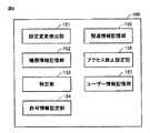
図6は、MFP100の機能的な構成の一例を模式的に示す図である。図6を参照して、MFP100の機能的な構成について、説明する。[Function Configuration of MFP 100]
FIG. 6 is a diagram schematically illustrating an example of a functional configuration of the
MFP100は、設定変更検出部151と、機器情報記憶部152と、判定部153と、許可情報設定部154と、関連情報記憶部155と、アクセス禁止設定部156と、ユーザー情報記憶部157とを含む。設定変更検出部151、判定部153、許可情報設定部154、およびアクセス禁止設定部156は、たとえば、後述する図7に示されるような処理を実行するCPU101によって実現される。機器情報記憶部152、関連情報記憶部155、およびユーザー情報記憶部157は、たとえば、補助記憶装置104によって実現される。 The
設定変更検出部151は、アクセスを禁止するアドレス(たとえば、IPアドレス)についてのフィルターの設定(たとえば、ルーターのサブネットマスク)の変更を検出する。つまり、たとえば、CPU101は、図3に示されたようにネットワーク301内にルーター300Bが設けられてネットワーク302が設定されたことを検出することにより、設定変更検出部151を実現する。 The setting
機器情報記憶部152は、アクセスを受けた機器についての履歴であって各機器のアドレスを含む履歴を記憶する。つまり、CPU101は、たとえば図2に示されたネットワーク301にログインしている機器のIPアドレスを、機器情報として、補助記憶装置104に格納する。当該機器情報を格納する補助記憶装置104によって、機器情報記憶部152を実現する。なお、機器情報は、ネットワーク301にログインしたことのある機器のうち一定の条件を満たす機器の情報のみを含んでもよい。つまり、たとえば、機器情報は、直前にMFP100がネットワーク301にログインしたときに、ネットワーク301にログインしていた機器のIPアドレスのみを含んでいてもよい。また、機器情報は、過去に少なくとも所定回数MFP100に対してアクセスした機器のIPアドレス(MFP100にアクセスした機器の履歴)のみを含んでいてもよい。当該機器情報を格納する補助記憶装置104によって、機器情報記憶部152を実現する。 The device
判定部153は、上記機器情報にIPアドレスを記憶された機器のうち、設定変更検出部151によって検出された変更後のフィルターによってMFP100へのアクセスを禁止される機器を特定する。つまり、CPU101は、たとえば図3に示されたネットワーク302においてMFP100Bの機器情報にMFP100A、端末200A、および端末200AのIPアドレスが登録されている場合に、ルーター300BのサブネットマスクによってMFP100Bへのアクセスが禁止されるようになる機器(MFP100A、端末200A、および端末200A)を特定することによって、判定部153を実現する。
許可情報設定部154は、判定部153によって特定された機器の中の少なくとも一部の機器についてアクセスを許可するための情報を設定する。つまり、CPU101が、たとえば、図3の画像処理システムにおいて上記のように特定されたMFP100A、端末200A、および端末200Aの中の少なくとも一部(図4では、MFP100Aおよび端末200A)のIPアドレスをフィルタリング除外IPとして補助記憶装置104に格納することによって、許可情報設定部154が実現される。 The permission
関連情報記憶部155は、MFP100と他の機器とを関連付けるための情報を記憶する。たとえば、MFP100では、製造元が当該MFP100と共通するMACアドレスの条件、それまでに当該MFP100がジョブを実行させるために当該ジョブを送信した他のMFP100のIPアドレス、MFP100にログインしたユーザーによってジョブの出力先として指定された他のMFP100のIPアドレス、当該MFP100と記憶装置を互いに連携させる制御(いわゆるBOX連携処理)を実行した他のMFP100のIPアドレス、または、省電力機能を連携した他のMFP100のIPアドレスが、関連情報として、補助記憶装置104に格納されている。つまり、MFP100では、たとえば、関連情報を記憶する補助記憶装置104によって、関連情報記憶部155が実現される。 The related
なお、記憶装置を連携させる制御は、たとえば、あるMFP100において、補助記憶装置104に格納されている情報とともに、連携相手のMFP100の補助記憶装置104に格納されている情報も閲覧できる制御である。また、省電力機能(Smart Grid)を連携させる制御は、たとえば、ネットワークにおけるジョブの実行効率に影響を与えることなく(または、影響を抑えつつ)、MFP100と他のMFP100とにおいて消費されるエネルギーの総和を提言させる制御である。 Note that the control for linking the storage devices is, for example, a control in which a
アクセス禁止設定部156は、MFP100が通信可能な機器であって、設定変更検出部151によって検出されたフィルターの設定によってはMFP100へのアクセスを禁止されない機器のうち、MFP100へのアクセスを禁止する機器を設定する。図4に示された画像処理システムにおいて、MFP100のCPU101は、アクセスを許可されている機器の情報(たとえば、機器の名称、IPアドレス、など)を表示し、ユーザーから当該表示された機器の中からアクセスを禁止する機器を選択を受け付ける。そして、CPU101は、選択された機器を、アクセスを禁止する機器として、たとえば補助記憶装置104に登録する。これにより、CPU101は、当該登録が解除されるまで、登録された機器からのアクセスを禁止する。このような処理を実行するCPU101により、アクセス禁止設定部156が実現される。 Access
ユーザー情報記憶部157は、MFP100にアクセスした機器にログインしているユーザーを特定する情報(たとえば、ユーザーID)を格納する。MFP100のCPU101は、当該MFP100にアクセスしてきたユーザーのIDを、たとえばユーザー履歴として、補助記憶装置104に格納する。つまり、たとえばユーザー履歴を格納する補助記憶装置104によって、ユーザー情報記憶部157が実現される。 User
[処理の流れ]
図7は、MFP100のCPU101によって実行される処理のフローチャートである。なお、図7の処理は、ネットワークにおけるアクセスについてのフィルターの設定の変更が検出されたときに実行される。つまり、図7の処理は、たとえば、図3のMFP100BのCPU101が、ネットワーク301内にネットワーク302(新たなサブネットフィルター)が設定されたことを検出したときに実行する処理である。[Process flow]
FIG. 7 is a flowchart of processing executed by
ステップS10で、CPU101は、MFP100におけるIPフィルタリング機能の変更により、利用できなくなる機器があるかどうかを判断する。IPフィルタリング機能の変更とは、新たなルーターにおけるサブネットマスクの設定を意味する。また、利用できなくなる機器とは、たとえば、それまでMFP100にアクセスできた機器であって、新たなサブネットマスクの設定によりアクセスができなくなる機器を意味する。 In step S <b> 10, the
CPU101は、ステップS10において、たとえば、上記した機器情報におけるIPアドレスのうち、新たに設定されたサブネットマスクによってMFP100に対するアクセスを禁止されるものを特定する。このようなIPアドレスの特定を行なうCPU101により、判定部153が構成される。そして、CPU101は、そのようなIPアドレスがある場合に、「利用できなくなる機器」があると判断する。そして、CPU101は、そのような機器(IPアドレス)があると判断すると(ステップS10でYES)、ステップS20へ制御を進める。一方、CPU101は、そのような機器が無いと判断すると(ステップS10でNO)、そのまま図7の処理を終了させる。 In step S <b> 10, for example, the
ステップS20で、CPU101は、ステップS10で「利用できなくなる機器」と判断した機器の情報を操作パネル107に表示する。表示される情報は、たとえば、当該機器のネットワーク上の名前や、IPアドレスである。そして、制御はステップS30へ進められる。 In step S <b> 20, the
ステップS30で、CPU101は、除外する機器が選択されたかどうかを判断する。当該選択の一例は、たとえばユーザーによる、除外する機器を選択するための操作である。他の例は、CPU101によって、上記した関連情報に登録されているIPアドレスと合致することが特定されることである。つまり、たとえば、CPU101は、ステップS10で「利用できなくなる機器」として特定された機器のうち、関連情報に登録されている機器を、ステップS30で選択してもよい。そして、CPU101は、除外する機器が選択されたと判断すると(ステップS30でYES)、ステップS40へ制御を進める。一方、CPU101は、除外する機器が選択されなかったと判断すると(ステップS30でNO)、ステップS50へ制御を進める。 In step S30, the
ステップS30では、たとえば、ステップS20で表示された機器に対してユーザーが選択しない意思を示す操作を実行すると、ステップS50へ制御が進められる。また、ステップS30では、たとえば、ステップS10で「利用できなくなる機器」と判断された機器が関連情報に登録された機器を含まない場合には、ステップS50へ制御を進められる。なお、ステップS30において関連情報が利用される場合には、ステップS20における機器の表示は省略されてもよい。 In step S30, for example, when an operation indicating that the user does not select the device displayed in step S20 is executed, the control proceeds to step S50. In step S30, for example, if the device determined as “unusable device” in step S10 does not include the device registered in the related information, the control proceeds to step S50. When related information is used in step S30, the display of the device in step S20 may be omitted.
ステップS40で、CPU101は、ステップS30で選択された機器を利用できなくなる機器から除外する設定を実行する。当該設定は、たとえばフィルタリング除外IP(図4参照)の設定である。ステップS40の制御を実行するCPU101により、許可情報設定部154が構成される。そして、制御はステップS50へ進められる。 In step S40, the
ステップS50で、CPU101は、利用が継続される機器の中で、利用できなくする機器が選択されたかどうかを判断する。より具体的には、ステップS50で、CPU101は、たとえば、フィルタリング機能の変更後も利用可能な機器のリストを操作パネル107に表示する。表示される機器は、図4の例では、たとえばネットワーク302内の機器およびフィルタリング除外IPにIPアドレスを登録された機器である。そして、CPU101は、ユーザーによる、リスト表示された機器の中から利用できなくする(MFP100へのアクセスを禁止させる)機器の選択を受け付ける。そして、CPU101は、当該機器の選択が入力されたと判断すると(ステップS50でYES)、ステップS60へ制御を進める。一方、CPU101は、そのような機器の選択がなかったと判断すると(ステップS50でNO)、図7の処理を終了させる。 In step S <b> 50, the
ステップS60で、CPU101は、ステップS50でMFP100へのアクセスを禁止する機器として選択された機器の情報を、「利用できなくなる」機器として、たとえば補助記憶装置104に格納する。これにより、「利用できなくなる」機器として、情報を格納された機器からのアクセスを拒否する。そして、CPU101は、図7の処理を終了する。 In step S <b> 60, the
以上説明された図7の処理により、MFP100は、当該MFP100が所属するネットワークにおけるアクセスについての設定が当該MFP100の利用の実情に沿わないように変更された場合であっても、当該実情に沿うように、MFP100にアクセス可能な機器またはMFP100にアクセスできなくなる機器を設定できる。 Through the processing in FIG. 7 described above, the
なお、MFP100は、上記のような設定の変更に際し、他の機器に当該設定の変更に関する情報を報知してもよい。このような報知を、図8を参照して説明する。図8は、アクセス設定の変更があった画像処理システムにおけるMFPの情報の報知態様の一例を説明するための図である。 When changing the setting as described above, the
図2を参照して説明した画像処理システムにおいて、MFP100Bには、端末200Aから、MFP100Aを出力先として指定されたジョブを受信した履歴が登録されているとする。当該図2の画像処理システムにおけるアクセス設定の変更により、図8に示されるように、端末200AはMFP100Bへのアクセスを許可されたが、MFP100AはMFP100Bへの履歴が禁止されたとする。 In the image processing system described with reference to FIG. 2, it is assumed that a history of receiving a job designated with
この場合、CPU101は、上記設定の変更後、端末200Aから、出力先としてMFP100Aを指定するジョブを受信すると、端末200Aに対して、MFP100BがMFP100Aにジョブを送信できないことを報知する。そして、CPU101は、MFP100Bが端末200Aから受信したジョブの実行を指示できるMFPを端末200Aに報知する。報知されるMFPは、たとえば、MFP100B自身、または、MFP100C(MFP100Bにアクセス可能なMFPの一例)を含む。 In this case, when the
端末200Aのユーザーは、報知されたMFP100の中から、ジョブを出力先のMFP100を指定する情報をMFP100Bに送信する。これに応じて、MFP100Bは、指定されたMFPにジョブの実行を指示する。 The user of
図8を参照して説明された処理により、端末200Aのユーザーは、ジョブを出力できないMFPを出力先として指定した場合に、再度、ジョブを出力できるMFPを、改めてジョブの出力先として指定できる。 With the processing described with reference to FIG. 8, when the user of the terminal 200 </ b> A designates an MFP that cannot output a job as an output destination, the MFP that can output the job can be designated again as a job output destination.
今回開示された各実施の形態は全ての点で例示であって制限的なものではないと考えられるべきである。本発明の範囲は上記した説明ではなくて特許請求の範囲によって示され、特許請求の範囲と均等の意味および範囲内での全ての変更が含まれることが意図される。また、実施の形態および各変形例において説明された発明は、可能な限り、単独でも、組合わせても、実施することが意図される。 Each embodiment disclosed this time must be considered as illustrative in all points and not restrictive. The scope of the present invention is defined by the terms of the claims, rather than the description above, and is intended to include any modifications within the scope and meaning equivalent to the terms of the claims. In addition, the invention described in the embodiment and each modification is intended to be carried out independently or in combination as much as possible.
100 MFP、104 補助記憶装置、107 操作パネル、108 スキャナー部、109 プリンター部、150 ウェブサーバー、151 設定変更検出部、152 機器情報記憶部、153 判定部、154 許可情報設定部、155 関連情報記憶部、156 アクセス禁止設定部、157 ユーザー情報記憶部、200,200A,200C,200D 端末、300A,300B ルーター、301,302 ネットワーク。 100 MFP, 104 Auxiliary storage device, 107 Operation panel, 108 Scanner unit, 109 Printer unit, 150 Web server, 151 Setting change detection unit, 152 Device information storage unit, 153 Judgment unit, 154 Permission information setting unit, 155 Related information storage Part, 156 access prohibition setting part, 157 user information storage part, 200, 200A, 200C, 200D terminal, 300A, 300B router, 301, 302 network.
Claims (10)
Translated fromJapaneseフィルターの設定の前記変更前にアクセスが可能な機器について、当該機器のアドレスを含む情報を記憶するための機器情報記憶手段と、
前記機器情報記憶手段に記憶された機器のうち、前記設定変更検出手段によって検出された変更後のフィルターによってアクセスを禁止される機器を特定するための特定手段と、
前記特定手段によって特定された機器の中の少なくとも一部の機器についてアクセスを許可するための情報を設定するための許可情報設定手段とを備える、画像処理装置。A setting change detection means for detecting a change in a filter setting for an address for which access is prohibited;
Device information storage means for storing information including an address of the device, with respect to the device accessible before the change of the filter setting;
Among the devices stored in the device information storage unit, a specifying unit for specifying a device whose access is prohibited by the changed filter detected by the setting change detection unit;
An image processing apparatus comprising: permission information setting means for setting information for permitting access to at least some of the devices specified by the specifying means.
前記許可情報設定手段は、前記特定手段によって特定された機器の中の、前記関連情報記憶手段に記憶された情報によって前記画像処理装置と関連付けられる機器について、アクセスを許可するための情報を設定する、請求項1または請求項2に記載の画像処理装置。Further comprising related information storage means for storing information for associating the image processing apparatus with another device;
The permission information setting unit sets information for permitting access to a device associated with the image processing apparatus according to information stored in the related information storage unit among the devices specified by the specifying unit. The image processing apparatus according to claim 1 or 2.
前記許可情報設定手段は、前記ユーザー情報記憶手段に記憶されたユーザーを特定する情報に関連付けられた機器を特定する情報を取得し、当該取得した情報によって特定される機器についてアクセスを許可する、請求項1〜請求項5のいずれか1項に記載の画像処理装置。A user information storage means for storing a history of users who have been accessed;
The permission information setting unit acquires information specifying a device associated with information specifying a user stored in the user information storage unit, and permits access to the device specified by the acquired information. The image processing apparatus according to any one of claims 1 to 5.
アクセスを禁止するアドレスについてのフィルターの設定の変更を検出するステップを備え、
前記画像処理装置は、フィルターの設定の前記変更前にアクセスが可能な機器について、当該機器のアドレスを含む情報を記憶する機器情報記憶手段を備え、
前記制御方法は、さらに、
前記機器情報記憶手段に記憶された機器のうち、検出された変更後の前記フィルターによってアクセスを禁止される機器を特定するステップと、
前記特定された機器の中の少なくとも一部の機器についてアクセスを許可するための情報を設定するステップとを含む、画像処理装置の制御方法。An image processing apparatus control method capable of restricting access, comprising:
Detecting a change in a filter setting for an address forbidden access;
The image processing apparatus includes a device information storage unit that stores information including an address of a device that can be accessed before the change of the filter setting.
The control method further includes:
Of the devices stored in the device information storage means, identifying a device whose access is prohibited by the detected changed filter;
And a step of setting information for permitting access to at least some of the specified devices.
前記プログラムは、前記コンピューターに、
アクセスを禁止するアドレスについてのフィルターの設定の変更を検出するステップを実行させ、
前記画像処理装置は、フィルターの設定の前記変更前にアクセスが可能な機器について、当該機器のアドレスを含む情報を記憶する機器情報記憶手段を備え、
前記プログラムは、前記コンピューターに、さらに、
アクセスを禁止するアドレスについてのフィルターの設定の変更を検出するステップと、
前記機器情報記憶手段に記憶された機器のうち、検出された変更後の前記フィルターによってアクセスを禁止される機器を特定するステップと、
前記特定された機器の中の少なくとも一部の機器についてアクセスを許可するための情報を設定するステップとを実行させる、プログラム。A program executed by a computer of an image processing apparatus capable of restricting access,
The program is stored in the computer.
Execute a step to detect changes in filter settings for addresses that are prohibited from access,
The image processing apparatus includes a device information storage unit that stores information including an address of a device that can be accessed before the change of the filter setting.
The program is further stored on the computer.
Detecting a change in a filter setting for an address forbidden access; and
Of the devices stored in the device information storage means, identifying a device whose access is prohibited by the detected changed filter;
And a step of setting information for permitting access to at least some of the identified devices.
Priority Applications (1)
| Application Number | Priority Date | Filing Date | Title |
|---|---|---|---|
| JP2014248835AJP6432324B2 (en) | 2014-12-09 | 2014-12-09 | Image processing apparatus, control method thereof, and program |
Applications Claiming Priority (1)
| Application Number | Priority Date | Filing Date | Title |
|---|---|---|---|
| JP2014248835AJP6432324B2 (en) | 2014-12-09 | 2014-12-09 | Image processing apparatus, control method thereof, and program |
Publications (2)
| Publication Number | Publication Date |
|---|---|
| JP2016111595Atrue JP2016111595A (en) | 2016-06-20 |
| JP6432324B2 JP6432324B2 (en) | 2018-12-05 |
Family
ID=56124959
Family Applications (1)
| Application Number | Title | Priority Date | Filing Date |
|---|---|---|---|
| JP2014248835AExpired - Fee RelatedJP6432324B2 (en) | 2014-12-09 | 2014-12-09 | Image processing apparatus, control method thereof, and program |
Country Status (1)
| Country | Link |
|---|---|
| JP (1) | JP6432324B2 (en) |
Citations (7)
| Publication number | Priority date | Publication date | Assignee | Title |
|---|---|---|---|---|
| JP2003114789A (en)* | 2001-07-30 | 2003-04-18 | Canon Inc | Image forming apparatus, data processing apparatus, and data processing method |
| JP2007108862A (en)* | 2005-10-11 | 2007-04-26 | Canon Inc | Method for controlling transition to sleep mode of network-connected peripheral device |
| JP2008153980A (en)* | 2006-12-18 | 2008-07-03 | Ricoh Co Ltd | Receiving terminal, visible information copying terminal, transmitting terminal, and search system |
| JP2010211266A (en)* | 2009-03-06 | 2010-09-24 | Seiko Epson Corp | Output apparatus |
| JP2011035670A (en)* | 2009-07-31 | 2011-02-17 | Brother Industries Ltd | Communication device and communication system |
| JP2011211612A (en)* | 2010-03-30 | 2011-10-20 | Nec Access Technica Ltd | Wireless lan terminal, wireless lan access point and wireless lan system |
| JP2013193418A (en)* | 2012-03-22 | 2013-09-30 | Ricoh Co Ltd | Image forming apparatus and image forming system |
- 2014
- 2014-12-09JPJP2014248835Apatent/JP6432324B2/ennot_activeExpired - Fee Related
Patent Citations (7)
| Publication number | Priority date | Publication date | Assignee | Title |
|---|---|---|---|---|
| JP2003114789A (en)* | 2001-07-30 | 2003-04-18 | Canon Inc | Image forming apparatus, data processing apparatus, and data processing method |
| JP2007108862A (en)* | 2005-10-11 | 2007-04-26 | Canon Inc | Method for controlling transition to sleep mode of network-connected peripheral device |
| JP2008153980A (en)* | 2006-12-18 | 2008-07-03 | Ricoh Co Ltd | Receiving terminal, visible information copying terminal, transmitting terminal, and search system |
| JP2010211266A (en)* | 2009-03-06 | 2010-09-24 | Seiko Epson Corp | Output apparatus |
| JP2011035670A (en)* | 2009-07-31 | 2011-02-17 | Brother Industries Ltd | Communication device and communication system |
| JP2011211612A (en)* | 2010-03-30 | 2011-10-20 | Nec Access Technica Ltd | Wireless lan terminal, wireless lan access point and wireless lan system |
| JP2013193418A (en)* | 2012-03-22 | 2013-09-30 | Ricoh Co Ltd | Image forming apparatus and image forming system |
Also Published As
| Publication number | Publication date |
|---|---|
| JP6432324B2 (en) | 2018-12-05 |
Similar Documents
| Publication | Publication Date | Title |
|---|---|---|
| JP6547356B2 (en) | Information processing apparatus and program | |
| JP5597556B2 (en) | Image forming apparatus, image forming apparatus setting method, and security setting apparatus | |
| US9985948B2 (en) | Image forming apparatus, information processing system, and non-transitory computer-readable medium | |
| JP6102264B2 (en) | Processing execution system, information processing apparatus, program | |
| US9733874B2 (en) | Image processing apparatus and method and non-transitory computer readable medium | |
| JP2008073973A (en) | Image formation device | |
| JP6520277B2 (en) | Information processing apparatus and program | |
| US9854116B2 (en) | Image processing apparatus configured to transmit image data and method for controlling an image processing apparatus | |
| US20100179965A1 (en) | Image processing apparatus and image processing method | |
| US8368908B2 (en) | Restriction of print job execution | |
| JP2011193309A (en) | Image forming system, user manager server device, and image forming device | |
| JP5773938B2 (en) | Image forming system and management server program | |
| JP2010226182A (en) | Image reading apparatus, image reading system and image reading program | |
| US20240020069A1 (en) | Information processing system, information processing apparatus, and control method for information processing system | |
| JP6135215B2 (en) | Image forming apparatus, network system, method and program | |
| JP6432324B2 (en) | Image processing apparatus, control method thereof, and program | |
| JP5636829B2 (en) | Customization system, image forming apparatus, information processing apparatus, and customization program | |
| JP5131223B2 (en) | Workflow execution device, workflow execution method, and workflow execution program | |
| JP4631729B2 (en) | Image forming apparatus and file transmission system | |
| JP2012105000A (en) | Multifunction peripheral control system, control program, and recording medium | |
| JP2011113259A (en) | Authorization information registration device and authorization information registration program | |
| JP6611033B2 (en) | Multifunction device, server device, and account deletion method | |
| US20170201644A1 (en) | Image forming apparatus and notification method | |
| JP5741336B2 (en) | Data processing system, output control device, output control method, output control program, data processing method, and data processing program | |
| JP4715312B2 (en) | Image forming apparatus, image forming system, file management program, and recording medium recording the program |
Legal Events
| Date | Code | Title | Description |
|---|---|---|---|
| A621 | Written request for application examination | Free format text:JAPANESE INTERMEDIATE CODE: A621 Effective date:20171109 | |
| A977 | Report on retrieval | Free format text:JAPANESE INTERMEDIATE CODE: A971007 Effective date:20180712 | |
| A131 | Notification of reasons for refusal | Free format text:JAPANESE INTERMEDIATE CODE: A131 Effective date:20180821 | |
| A521 | Request for written amendment filed | Free format text:JAPANESE INTERMEDIATE CODE: A523 Effective date:20180925 | |
| TRDD | Decision of grant or rejection written | ||
| A01 | Written decision to grant a patent or to grant a registration (utility model) | Free format text:JAPANESE INTERMEDIATE CODE: A01 Effective date:20181009 | |
| A61 | First payment of annual fees (during grant procedure) | Free format text:JAPANESE INTERMEDIATE CODE: A61 Effective date:20181022 | |
| R150 | Certificate of patent or registration of utility model | Ref document number:6432324 Country of ref document:JP Free format text:JAPANESE INTERMEDIATE CODE: R150 | |
| LAPS | Cancellation because of no payment of annual fees |