Movatterモバイル変換


[0]ホーム

URL:


JP2016110775A - Switch device for vehicles - Google Patents

Switch device for vehicles
Download PDF

Info

Publication number
JP2016110775A
JP2016110775AJP2014245742AJP2014245742AJP2016110775AJP 2016110775 AJP2016110775 AJP 2016110775AJP 2014245742 AJP2014245742 AJP 2014245742AJP 2014245742 AJP2014245742 AJP 2014245742AJP 2016110775 AJP2016110775 AJP 2016110775A
Authority
JP
Japan
Prior art keywords
touch
light source
light
switch device
area
Prior art date
Legal status (The legal status is an assumption and is not a legal conclusion. Google has not performed a legal analysis and makes no representation as to the accuracy of the status listed.)
Pending
Application number
JP2014245742A
Other languages
Japanese (ja)
Inventor
祐一郎 重松
Yuichiro Shigematsu
祐一郎 重松
良子 中野
Ryoko Nakano
良子 中野
英貴 野村
Hidetaka Nomura
英貴 野村
Current Assignee (The listed assignees may be inaccurate. Google has not performed a legal analysis and makes no representation or warranty as to the accuracy of the list.)
Tokai Rika Co Ltd
Original Assignee
Tokai Rika Co Ltd
Priority date (The priority date is an assumption and is not a legal conclusion. Google has not performed a legal analysis and makes no representation as to the accuracy of the date listed.)
Filing date
Publication date
Application filed by Tokai Rika Co LtdfiledCriticalTokai Rika Co Ltd
Priority to JP2014245742ApriorityCriticalpatent/JP2016110775A/en
Publication of JP2016110775ApublicationCriticalpatent/JP2016110775A/en
Pendinglegal-statusCriticalCurrent

Links

Images

Landscapes

Abstract

PROBLEM TO BE SOLVED: To improve an operational feeling by giving feedback timely when a touch operation is performed.SOLUTION: A switch device for vehicles comprises: a light source; a display region where outgoing light emitted from the light source is transmitted and displayed; a touch switch part whose electrostatic capacitance is changed by a touch operation to a touch region; a touch detector that detects the touch operation on the basis of the change in the electrostatic capacitance; and a light source controller that changes quantity of the outgoing light on the basis of the touch operation.SELECTED DRAWING: Figure 4

Description

Translated fromJapanese

本発明は、車両用スイッチ装置に関する。  The present invention relates to a vehicle switch device.

従来、自動車等の車両には、種々の車載機器を運転者等が操作するためのスイッチ装置が備えられている。このようなスイッチ装置として、種々の操作項目が操作パネル上に表示され、操作者が触れた位置に表示された操作項目が選択されるスイッチ装置が知られている。かかるスイッチ装置の一態様として、操作者によって押下される形式のボタンスイッチではなく、操作者の指等が操作パネルに触れたことを検出可能な静電容量式のタッチスイッチを備えたものがある。  2. Description of the Related Art Conventionally, a vehicle such as an automobile is provided with a switch device for a driver or the like to operate various in-vehicle devices. As such a switch device, there is known a switch device in which various operation items are displayed on an operation panel and an operation item displayed at a position touched by an operator is selected. As one aspect of such a switch device, there is one provided with a capacitive touch switch that can detect that an operator's finger or the like has touched the operation panel, instead of a button switch that is pressed by the operator. .

例えば、特許文献1には、静電容量式の静電スイッチ部と、静電スイッチ部における静電容量の変化量の測定値が閾値以上となった場合に操作者の指が操作パネルに接触したことを検出する接触検出部とを備えた車両用静電タッチパネルが開示されている。かかる静電スイッチ部は、例えば、フレキシブル基板等の基板の表面に、所定の電極パターンが形成された電極部と絶縁カバーとがこの順に積層配置されて構成される。  For example,Patent Document 1 discloses a capacitance-type electrostatic switch unit, and an operator's finger touches an operation panel when a measured value of the amount of change in capacitance in the electrostatic switch unit exceeds a threshold value. An electrostatic touch panel for a vehicle that includes a contact detection unit that detects the occurrence of the failure is disclosed. Such an electrostatic switch unit is configured, for example, by laminating and arranging an electrode unit having a predetermined electrode pattern and an insulating cover in this order on the surface of a substrate such as a flexible substrate.

特開2012−118903号公報JP 2012-118903 A

しかしながら、特許文献1等に記載された従来の車両用スイッチ装置では、タッチ操作時に適時にフィードバックがなく、良好な操作感が得られにくい。すなわち、従来の車両用スイッチ装置は、実際に入力操作が行われたか否かを、操作者が実感しにくいものとなっている。例えば、空調装置(エアコンディショナ)の設定温度が、静電容量式のタッチスイッチにより調節されるとする。この場合、タッチ操作に伴って設定温度の数値の表示が切り替わるのみでは、得られる操作感は低いものとなる。また、空調装置の設定温度の操作以外に、そのような数値の表示を伴わない操作の場合には、適時にフィードバックがないと、得られる操作感はさらに低いものとなる。  However, the conventional vehicle switch device described inPatent Document 1 or the like does not provide feedback in a timely manner during a touch operation, and it is difficult to obtain a good operational feeling. That is, in the conventional vehicle switch device, it is difficult for an operator to realize whether or not an input operation has actually been performed. For example, it is assumed that the set temperature of the air conditioner (air conditioner) is adjusted by a capacitive touch switch. In this case, the operation feeling obtained is low only by switching the display of the numerical value of the set temperature in accordance with the touch operation. Further, in the case of an operation that does not involve the display of numerical values other than the operation of the set temperature of the air conditioner, the operational feeling obtained is further reduced if there is no feedback in a timely manner.

そこで、本発明は、上記問題に鑑みてなされたものであり、本発明の目的とするところは、タッチ操作時に適時にフィードバックを与え、操作感を向上させることが可能な車両用スイッチ装置を提供することにある。  Accordingly, the present invention has been made in view of the above problems, and an object of the present invention is to provide a vehicle switch device that can provide feedback in a timely manner during a touch operation and improve the operational feeling. There is to do.

上記課題を解決するために、本発明のある観点によれば、光源と、前記光源から出射される出射光が透過して表示される表示領域と、タッチ領域へのタッチ操作により静電容量が変化するタッチスイッチ部と、前記静電容量の変化に基づき前記タッチ操作を検出するタッチ検出部と、前記タッチ操作に基づいて前記出射光の光量を変化させる光源制御部と、を備える、車両用スイッチ装置が提供される。  In order to solve the above problems, according to an aspect of the present invention, a capacitance is obtained by a touch operation on a light source, a display area through which emitted light emitted from the light source is transmitted, and a touch operation on the touch area. A vehicle comprising: a touch switch unit that changes; a touch detection unit that detects the touch operation based on a change in the capacitance; and a light source control unit that changes a light amount of the emitted light based on the touch operation. A switch device is provided.

前記光源は複数の光源を含み、前記タッチ領域は、所定の車載機器を操作するための第1のタッチ領域及び第2のタッチ領域を有し、前記光源制御部は、前記タッチ操作が行われたタッチ領域に対応して、異なる前記光源の前記出射光の光量を変化させてもよい。  The light source includes a plurality of light sources, the touch area includes a first touch area and a second touch area for operating a predetermined in-vehicle device, and the light source control unit performs the touch operation. The amount of the emitted light of the different light source may be changed corresponding to the touch area.

前記複数の光源は、前記第1のタッチ領域及び前記第2のタッチ領域の配置に対応するように配列され、前記光源制御部は、前記タッチ操作が行われたタッチ領域に対応する位置の前記光源の前記出射光の光量を増加させてもよい。  The plurality of light sources are arranged to correspond to the arrangement of the first touch area and the second touch area, and the light source control unit is located at a position corresponding to the touch area where the touch operation is performed. The amount of the emitted light from the light source may be increased.

前記光源制御部は、前記タッチ操作が行われないタッチ領域に対応する位置の前記光源の前記出射光の光量を減少させてもよい。  The light source control unit may reduce the amount of the emitted light of the light source at a position corresponding to a touch area where the touch operation is not performed.

前記光源制御部は、前記光源の駆動デューティ比、前記光源への供給電流、及び点灯させる前記光源の数のうちの少なくとも一つを変化させることにより、前記出射光の光量を変化させてもよい。  The light source control unit may change the amount of the emitted light by changing at least one of a driving duty ratio of the light source, a supply current to the light source, and the number of the light sources to be lit. .

前記光源は、互いに色が異なる複数の光源を含んでもよい。  The light source may include a plurality of light sources having different colors.

前記表示領域と前記タッチ領域とが互いに重なってもよい。  The display area and the touch area may overlap each other.

以上説明したように本発明によれば、タッチ操作時に、出射光の表示によるフィードバックが適時に与えられ、車両用スイッチ装置の操作感を向上することが可能である。  As described above, according to the present invention, feedback by displaying emitted light is provided in a timely manner during a touch operation, and the operational feeling of the vehicular switch device can be improved.

本発明の第1の実施の形態にかかる車両用のスイッチ装置を備えた車両を示す説明図である。It is explanatory drawing which shows the vehicle provided with the switch apparatus for vehicles concerning the 1st Embodiment of this invention.第1の実施の形態にかかるスイッチ装置の操作部分を示す説明図である。It is explanatory drawing which shows the operation part of the switch apparatus concerning 1st Embodiment.第1の実施の形態にかかるスイッチ装置の構成を示す説明図である。It is explanatory drawing which shows the structure of the switch apparatus concerning 1st Embodiment.第1の実施の形態にかかるスイッチ装置の構成を示すブロック図である。It is a block diagram which shows the structure of the switch apparatus concerning 1st Embodiment.第1の実施の形態にかかるスイッチ装置のフィードバック動作を示す説明図である。It is explanatory drawing which shows the feedback operation | movement of the switch apparatus concerning 1st Embodiment.第1の実施の形態にかかるスイッチ装置のフィードバック動作を示す説明図である。It is explanatory drawing which shows the feedback operation | movement of the switch apparatus concerning 1st Embodiment.第1の実施の形態にかかるスイッチ装置のフィードバック動作を示す説明図である。It is explanatory drawing which shows the feedback operation | movement of the switch apparatus concerning 1st Embodiment.変形例にかかるスイッチ装置のフィードバック動作を示す説明図である。It is explanatory drawing which shows the feedback operation | movement of the switch apparatus concerning a modification.変形例にかかるスイッチ装置のフィードバック動作を示す説明図である。It is explanatory drawing which shows the feedback operation | movement of the switch apparatus concerning a modification.本発明の第2の実施の形態にかかるスイッチ装置の操作部分を示す説明図である。It is explanatory drawing which shows the operation part of the switch apparatus concerning the 2nd Embodiment of this invention.第2の実施の形態にかかるスイッチ装置の構成を示す説明図である。It is explanatory drawing which shows the structure of the switch apparatus concerning 2nd Embodiment.第2の実施の形態にかかるスイッチ装置のフィードバック動作を示す説明図である。It is explanatory drawing which shows the feedback operation | movement of the switch apparatus concerning 2nd Embodiment.第2の実施の形態にかかるスイッチ装置のフィードバック動作を示す説明図である。It is explanatory drawing which shows the feedback operation | movement of the switch apparatus concerning 2nd Embodiment.第2の実施の形態にかかるスイッチ装置のフィードバック動作を示す説明図である。It is explanatory drawing which shows the feedback operation | movement of the switch apparatus concerning 2nd Embodiment.

以下に添付図面を参照しながら、本発明の実施の形態について詳細に説明する。なお、本明細書及び図面において、実質的に同一の機能構成を有する構成要素については、同一の符号を付することにより重複説明を省略する。  Hereinafter, embodiments of the present invention will be described in detail with reference to the accompanying drawings. In addition, in this specification and drawing, about the component which has the substantially same function structure, duplication description is abbreviate | omitted by attaching | subjecting the same code | symbol.

また、本明細書及び図面において、実質的に同一の機能構成を有する複数の構成要素を、同一の符号の後に異なるアルファベットを付して区別する場合もある。ただし、実質的に同一の機能構成を有する複数の構成要素の各々を特に区別する必要がない場合、同一符号のみを付する。  In the present specification and drawings, a plurality of components having substantially the same functional configuration may be distinguished by adding different alphabets after the same reference numeral. However, when it is not necessary to particularly distinguish each of a plurality of constituent elements having substantially the same functional configuration, only the same reference numerals are given.

<<1.第1の実施の形態>>
<1−1.車両用スイッチ装置の構成>
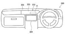
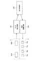
まず、図1〜図4を参照し、本発明の第1の実施の形態にかかる車両用のスイッチ装置100の構成を説明する。図1は、本実施形態にかかるスイッチ装置100を備えた車両300の車室内前方を示す概略図である。図2は、本実施形態にかかるスイッチ装置100の操作部分の一部を示す概略説明図である。図2に示した操作部分は、図1に点線で示した領域Aに相当する。図3は、図2のXX断面を矢印方向に見た概略断面図である。図4は、本実施形態にかかるスイッチ装置100のブロック図である。
<< 1. First embodiment >>
<1-1. Configuration of switch device for vehicle>
First, with reference to FIGS. 1-4, the structure of theswitch apparatus 100 for vehicles concerning the 1st Embodiment of this invention is demonstrated. FIG. 1 is a schematic view showing the front side of avehicle 300 having aswitch device 100 according to the present embodiment. FIG. 2 is a schematic explanatory view showing a part of the operation part of theswitch device 100 according to the present embodiment. The operation part shown in FIG. 2 corresponds to a region A indicated by a dotted line in FIG. FIG. 3 is a schematic cross-sectional view of the XX cross-section of FIG. 2 viewed in the direction of the arrow. FIG. 4 is a block diagram of theswitch device 100 according to the present embodiment.

図2に示したように、本実施形態では、車両300の空調装置の設定温度を調節するためのスイッチ装置を例に採って説明する。ただし、スイッチ装置100は、空調装置の操作を行うためのスイッチ装置に限られない。車両300に備えられた種々の車載機器の操作を行うための、静電容量式のスイッチ装置であれば、本発明を適用することができる。  As shown in FIG. 2, in this embodiment, a switch device for adjusting the set temperature of the air conditioner of thevehicle 300 will be described as an example. However, theswitch device 100 is not limited to the switch device for operating the air conditioner. The present invention can be applied to any capacitance type switch device for operating various in-vehicle devices provided in thevehicle 300.

図1に示したように、車両300の車室の前方には、計器類やグローブボックス等が装着されたインストルメントパネル302が車幅方向に沿って備えられている。インストルメントパネル302の中央部には、センタクラスタ303が配置されている。センタクラスタ303は、ディスプレイ装置304や空調パネル305、オーディオ機器の操作パネル(図示せず)等を備える。空調パネル305は、車載機器としての空調装置を操作するための入力操作部であり、空調装置の制御部に対して、空調パネル305への入力操作に応じた出力信号を送信する。かかる空調パネル305は、タッチ操作によって入力操作が行われる。  As shown in FIG. 1, aninstrument panel 302 equipped with instruments, a glove box, and the like is provided in the vehicle width direction in front of the passenger compartment of thevehicle 300. Acenter cluster 303 is arranged at the center of theinstrument panel 302. Thecenter cluster 303 includes adisplay device 304, anair conditioning panel 305, an audio device operation panel (not shown), and the like. Theair conditioning panel 305 is an input operation unit for operating an air conditioner as an in-vehicle device, and transmits an output signal corresponding to an input operation to theair conditioning panel 305 to the control unit of the air conditioner. Theair conditioning panel 305 is input by a touch operation.

図2及び図3に示したように、スイッチ装置100は、表示領域110を有する。表示領域110では、照明装置2に備えられた青色光源70a,70b及び赤色光源75a,75bから出射される光が透過して、操作者等に視認され得る。また、スイッチ装置100は、第1のタッチ領域120a及び第2のタッチ領域120bを有する。本実施形態では、第1のタッチ領域120aが、設定温度を下げる操作を行うためのタッチ領域であり、第2のタッチ領域120bが、設定温度を上げる操作を行うためのタッチ領域である。本実施形態にかかるスイッチ装置100では、第1のタッチ領域120a及び第2のタッチ領域120bは、表示領域110に重なる位置に設けられている。  As shown in FIGS. 2 and 3, theswitch device 100 has adisplay area 110. In thedisplay area 110, light emitted from theblue light sources 70a and 70b and thered light sources 75a and 75b provided in theillumination device 2 is transmitted and can be visually recognized by an operator or the like. In addition, theswitch device 100 includes afirst touch area 120a and asecond touch area 120b. In the present embodiment, thefirst touch area 120a is a touch area for performing an operation for decreasing the set temperature, and thesecond touch area 120b is a touch area for performing an operation for increasing the set temperature. In theswitch device 100 according to the present embodiment, thefirst touch area 120 a and thesecond touch area 120 b are provided at positions that overlap thedisplay area 110.

本実施形態にかかるスイッチ装置100は、タッチスイッチ部5を有する意匠パネル1と、意匠パネル1の背面側に配置された照明装置2とを備えて構成される。また、図4に示したように、スイッチ装置100は、タッチスイッチ部5の静電容量の変化に基づいてタッチ操作を検出するタッチ検出回路152と、タッチ操作に応じて光源の駆動制御を行う光源制御部150と、光源制御部150からの駆動指令に基づいて光源を駆動する光源駆動回路154とを備える。本実施形態では、タッチ検出回路152が本発明におけるタッチ検出部に対応する。  Theswitch device 100 according to the present embodiment includes adesign panel 1 having atouch switch unit 5 and alighting device 2 arranged on the back side of thedesign panel 1. Further, as illustrated in FIG. 4, theswitch device 100 performs atouch control circuit 152 that detects a touch operation based on a change in capacitance of thetouch switch unit 5, and performs drive control of the light source according to the touch operation. The lightsource control unit 150 includes a lightsource drive circuit 154 that drives the light source based on a drive command from the lightsource control unit 150. In the present embodiment, thetouch detection circuit 152 corresponds to the touch detection unit in the present invention.

(1−1−1.意匠パネル)
意匠パネル1は、基材としても機能する成形樹脂板30の表示面側に、遮光層20及び表面層10を備える。遮光層20及び表面層10は、この順に成形樹脂板30上に積層されている。また、意匠パネル1は、成形樹脂板30の背面側に、拡散フィルム40、フィルム基板50及び検出電極60A,60Bを備える。拡散フィルム40、フィルム基板50及び検出電極60A,60Bは、この順に成形樹脂板30上に積層されている。フィルム基板50及び検出電極60A,60Bによりタッチスイッチ部5が構成される。
(1-1-1. Design panel)
Thedesign panel 1 includes alight shielding layer 20 and asurface layer 10 on the display surface side of the moldedresin plate 30 that also functions as a base material. Thelight shielding layer 20 and thesurface layer 10 are laminated on the moldedresin plate 30 in this order. Thedesign panel 1 includes adiffusion film 40, afilm substrate 50, anddetection electrodes 60A and 60B on the back side of the moldedresin plate 30. Thediffusion film 40, thefilm substrate 50, and thedetection electrodes 60A and 60B are laminated on the moldedresin plate 30 in this order. Thetouch switch unit 5 is configured by thefilm substrate 50 and thedetection electrodes 60A and 60B.

成形樹脂板30は、例えばアクリル系樹脂又はポリカーボネート樹脂等の光透過性を有する透明樹脂材料により成形される。成形樹脂板30の構成材料は、光透過性を有する材料であれば、例示した樹脂材料以外の材料であってもよい。本実施形態では、成形樹脂板30はスモークグレーに着色され、青色光源70a,70b及び赤色光源75a,75bの消灯時に、意匠パネル1の表示領域110が視認されにくくなるブラックアウト仕様となっている。これにより、意匠パネル1の意匠性が高められている。  The moldedresin plate 30 is molded from a transparent resin material having light transmissivity, such as an acrylic resin or a polycarbonate resin. The constituent material of the moldedresin plate 30 may be a material other than the exemplified resin material as long as it is a light-transmitting material. In the present embodiment, the moldedresin plate 30 is colored in smoke gray and has a blackout specification that makes it difficult to visually recognize thedisplay area 110 of thedesign panel 1 when theblue light sources 70a and 70b and thered light sources 75a and 75b are turned off. . Thereby, the design property of thedesign panel 1 is improved.

遮光層20は、表示領域110以外の領域において、青色光源70a,70b及び赤色光源75a,75bから出射された光を遮り、表示領域110以外の領域で出射光が、操作者等によって視認されないようにする。すなわち、遮光層20が形成されない領域が、出射光が透過して視認され得る表示領域110となる。遮光層20は、例えば、表示領域110に対応する領域を除き、成形樹脂板30に対してシルク印刷等を施すことにより形成される。遮光層20は、表面層10の裏面に印刷等されて形成されてもよい。  Thelight shielding layer 20 blocks light emitted from theblue light sources 70a and 70b and thered light sources 75a and 75b in an area other than thedisplay area 110 so that the emitted light is not visually recognized by an operator or the like in an area other than thedisplay area 110. To. That is, the area where thelight shielding layer 20 is not formed becomes thedisplay area 110 through which the emitted light can be transmitted and viewed. Thelight shielding layer 20 is formed, for example, by performing silk printing or the like on the moldedresin plate 30 except for an area corresponding to thedisplay area 110. Thelight shielding layer 20 may be formed by printing or the like on the back surface of thesurface layer 10.

遮光層20が形成されない領域、すなわち、表示領域110は、文字や数字、図形、記号等により形成される。図2の例では、横長の六角形の図形が象られた表示領域110と、「TEMP」の文字が象られた表示領域とが形成されている。  The area where thelight shielding layer 20 is not formed, that is, thedisplay area 110 is formed of characters, numbers, figures, symbols, and the like. In the example of FIG. 2, adisplay area 110 in which a horizontally long hexagonal figure is formed and a display area in which a character “TEMP” is formed are formed.

表面層10は、例えば、光透過性の透明樹脂材料からなる樹脂板、樹脂フィルム又は樹脂シートにより形成される。表面層10は、意匠パネル1の表面を平滑にする機能を有するとともに、遮光層20を保護する機能を有する。成形樹脂板30の代わりに、表面層10がスモークグレーに着色されることによっても、ブラックアウト仕様とされ得る。第1のタッチ領域120a及び第2のタッチ領域120bの表面層10に触れることによって、意匠パネル1への入力操作が行われる。  Thesurface layer 10 is formed of, for example, a resin plate, a resin film, or a resin sheet made of a light transmissive transparent resin material. Thesurface layer 10 has a function of smoothing the surface of thedesign panel 1 and a function of protecting thelight shielding layer 20. Instead of the moldedresin plate 30, thesurface layer 10 may be colored in smoked gray so as to have a blackout specification. An input operation to thedesign panel 1 is performed by touching thesurface layer 10 of thefirst touch area 120a and thesecond touch area 120b.

拡散フィルム40は、青色光源70a,70b及び赤色光源75a,75bから出射された光を拡散して、均一な光として表示領域110に送る機能を有する。拡散フィルム40は、公知の拡散フィルムを適宜使用することができる。  Thediffusion film 40 has a function of diffusing light emitted from theblue light sources 70a and 70b and thered light sources 75a and 75b and sending the light to thedisplay area 110 as uniform light. As thediffusion film 40, a known diffusion film can be appropriately used.

タッチスイッチ部5は、静電容量式のタッチスイッチであり、拡散フィルム40の背面側に配置されている。かかるタッチスイッチ部5は、光透過性のフィルム基板50上に、ITO(Indium Tin Oxide)等の金属酸化物の薄膜からなるタッチ検出電極60A,60Bを備える。タッチ検出電極60A,60Bは、光透過性の透明電極であり、パターニングされて形成されている。タッチ検出電極60A,60B上にさらに絶縁層が備えられていてもよい。  Thetouch switch unit 5 is a capacitive touch switch and is disposed on the back side of thediffusion film 40. Thetouch switch unit 5 includestouch detection electrodes 60A and 60B made of a metal oxide thin film such as ITO (Indium Tin Oxide) on a light-transmittingfilm substrate 50. Thetouch detection electrodes 60A and 60B are light transmissive transparent electrodes, and are formed by patterning. An insulating layer may be further provided on thetouch detection electrodes 60A and 60B.

タッチ検出電極60A,60Bが形成される領域が、タッチ領域となる。本実施形態では、タッチ検出電極60Aが形成された領域が第1のタッチ領域120aに相当し、タッチ検出電極60Bが形成された領域が第2のタッチ領域120bに相当する。タッチ検出電極60A,60Bは、各タッチ領域への操作者のタッチ操作に基づいて静電容量を形成する。  A region where thetouch detection electrodes 60A and 60B are formed is a touch region. In the present embodiment, the region where thetouch detection electrode 60A is formed corresponds to thefirst touch region 120a, and the region where thetouch detection electrode 60B is formed corresponds to thesecond touch region 120b. Thetouch detection electrodes 60A and 60B form capacitance based on an operator's touch operation on each touch area.

なお、タッチスイッチ部5の構成は、上記の例に限られず、他の構成を有していてもよい。例えば、固定電極及び変位電極を有し、変位電極の位置の変化に伴って両電極間に形成される静電容量が変化する構成のタッチスイッチ部5としてもよい。また、タッチスイッチ部5は、意匠パネル1の内部に、中間層として設けられてもよい。  In addition, the structure of thetouch switch part 5 is not restricted to said example, You may have another structure. For example, thetouch switch unit 5 may be configured to have a fixed electrode and a displacement electrode, and the capacitance formed between the two electrodes changes as the position of the displacement electrode changes. Further, thetouch switch unit 5 may be provided as an intermediate layer inside thedesign panel 1.

(1−1−2.照明装置)
照明装置2は、基板80と、当該基板80上に実装された青色光源70a,70b及び赤色光源75a,75bと、遮光壁90とを備える。本実施形態では、青色光源70a,70b及び赤色光源75a,75bは、LED(Light Emitting Diode)により構成される。青色光源70a,70bは、第1のタッチ領域120aに対応する位置、すなわち、タッチ検出電極60Aの背面側に配置されている。赤色光源75a,75bは、第2のタッチ領域120bに対応する位置、すなわち、タッチ検出電極60Bの背面側に配置されている。
(1-1-2. Lighting device)
Theillumination device 2 includes asubstrate 80, bluelight sources 70 a and 70 b andred light sources 75 a and 75 b mounted on thesubstrate 80, and alight shielding wall 90. In the present embodiment, theblue light sources 70a and 70b and thered light sources 75a and 75b are configured by LEDs (Light Emitting Diode). Theblue light sources 70a and 70b are arranged at positions corresponding to thefirst touch region 120a, that is, on the back side of thetouch detection electrode 60A. Thered light sources 75a and 75b are arranged at positions corresponding to thesecond touch region 120b, that is, on the back side of thetouch detection electrode 60B.

光源は、LED以外の光源であってもよい。例えば、LD(Laser Diode)やEL(Electroluminescence)等により構成される光源であってもよい。かかる光源は、印加する電圧の大きさに応じて出射光の光量が変化し得る。また、かかる光源は、印加する電圧が一定であっても、単位時間当たりの電圧を印加する時間の割合(以下、「駆動デューティ比」ともいう。)や供給電流の大きさに応じて出射光の光量が変化し得る。さらに、供給電流のオンオフによって点灯及び消灯が切り替わる光源であってもよい。すなわち、かかる光源は、供給電流のオンオフによって出射光の光量が変化し得る。  The light source may be a light source other than an LED. For example, it may be a light source configured by LD (Laser Diode), EL (Electroluminescence), or the like. In such a light source, the amount of emitted light can be changed according to the magnitude of the applied voltage. Further, even if the applied voltage is constant, the light source emits light in accordance with the ratio of the time for applying the voltage per unit time (hereinafter also referred to as “drive duty ratio”) and the magnitude of the supplied current. The amount of light can vary. Further, the light source may be switched on and off by turning on and off the supply current. That is, in such a light source, the amount of emitted light can be changed by turning on and off the supply current.

本実施形態では、第1のタッチ領域120aは、空調装置の設定温度を下げる操作を行うためのタッチ領域であるため、第1のタッチ領域120aに対応する位置に、涼しさをイメージさせる青色光源70a,70bが配置されている。また、第2のタッチ領域120bは、空調装置の設定温度を上げる操作を行うためのタッチ領域であるため、第2のタッチ領域120bに対応する位置に、暖かさをイメージさせる赤色光源75a,75bが配置されている。  In the present embodiment, since thefirst touch area 120a is a touch area for performing an operation for lowering the set temperature of the air conditioner, a blue light source that causes coolness to be imaged at a position corresponding to thefirst touch area 120a. 70a and 70b are arranged. In addition, since thesecond touch area 120b is a touch area for performing an operation for increasing the set temperature of the air conditioner,red light sources 75a and 75b that image warmth at positions corresponding to thesecond touch area 120b. Is arranged.

なお、本実施形態では、青色光源70a,70b及び赤色光源75a,75bがそれぞれ2つずつ備えられているが、青色光源70a,70b及び赤色光源75a,75bはそれぞれ3つ以上備えられていてもよい。光源の数は、例えば、表示領域の面積に応じて選択し得る。また、本実施形態では、青色光源70a,70b及び赤色光源75a,75bが一列に配置されているが、青色光源70a,70b及び赤色光源75a,75bは二列以上の複数列に配置されていてもよい。  In the present embodiment, twoblue light sources 70a and 70b and twored light sources 75a and 75b are provided, but three or more bluelight sources 70a and 70b and threered light sources 75a and 75b may be provided. Good. The number of light sources can be selected according to the area of the display region, for example. In the present embodiment, theblue light sources 70a and 70b and thered light sources 75a and 75b are arranged in a row, but theblue light sources 70a and 70b and thered light sources 75a and 75b are arranged in a plurality of rows of two or more. Also good.

遮光壁90は、表示領域110に対応する領域の外周を取り囲むように配置されている。遮光壁90は、両端がそれぞれ照明装置2の基板80と意匠パネル1の拡散フィルム40とに当接して設けられる。かかる遮光壁90は、表示領域110に表示を行う青色光源70a,70b及び赤色光源75a,75bから出射された光が他の表示領域へ進入しないように、出射光を遮る。一方、青色光源70a,70bと赤色光源75a,75bとの間、すなわち、表示領域110内には遮光壁は設けられず、表示領域110の一部において、青色光及び赤色光が混じり合う。  Thelight shielding wall 90 is disposed so as to surround the outer periphery of the area corresponding to thedisplay area 110. Both ends of thelight shielding wall 90 are provided in contact with thesubstrate 80 of thelighting device 2 and thediffusion film 40 of thedesign panel 1. Thelight shielding wall 90 blocks the emitted light so that the light emitted from theblue light sources 70a and 70b and thered light sources 75a and 75b that display in thedisplay area 110 does not enter the other display areas. On the other hand, no light shielding wall is provided between the bluelight sources 70 a and 70 b and thered light sources 75 a and 75 b, that is, in thedisplay area 110, and blue light and red light are mixed in a part of thedisplay area 110.

(1−1−3.タッチ検出回路)
タッチ検出回路152は、タッチスイッチ部5のタッチ検出電極60A,60Bに接続され、タッチスイッチ部5の静電容量の変化に基づいて、操作者のタッチ操作を検出する。本実施形態にかかるスイッチ装置100では、操作者がタッチ領域に触れると、操作者の指とタッチ検出電極60A,60Bとの間に静電容量が形成されることから、かかる静電容量の変化がタッチ検出回路152により検出される。タッチ検出回路152は、静電容量の変化量が所定の閾値を超えたときに、操作者のタッチ操作を検出してもよい。タッチ検出回路152は、オペアンプや発振器、整流器、フィルタ回路等を用いて構成することができる。
(1-1-3. Touch detection circuit)
Thetouch detection circuit 152 is connected to the touch detection electrodes 60 </ b> A and 60 </ b> B of thetouch switch unit 5, and detects an operator's touch operation based on a change in capacitance of thetouch switch unit 5. In theswitch device 100 according to the present embodiment, when the operator touches the touch area, a capacitance is formed between the finger of the operator and thetouch detection electrodes 60A and 60B. Is detected by thetouch detection circuit 152. Thetouch detection circuit 152 may detect an operator's touch operation when the amount of change in capacitance exceeds a predetermined threshold. Thetouch detection circuit 152 can be configured using an operational amplifier, an oscillator, a rectifier, a filter circuit, or the like.

本実施形態では、タッチ検出回路152は、タッチ検出電極60Aにおける静電容量の変化及びタッチ検出電極60Bにおける静電容量の変化をそれぞれ検出し得る。すなわち、タッチ検出回路152は、タッチ検出電極60Aにおける静電容量の変化に基づき、第1のタッチ領域120aへのタッチ操作を検出する。また、タッチ検出回路152は、タッチ検出電極60Bにおける静電容量の変化に基づき、第2のタッチ領域120bへのタッチ操作を検出する。タッチ検出回路152は、静電容量の変化に基づきタッチ操作を検出した場合には、検出信号を光源制御部150に出力する。  In the present embodiment, thetouch detection circuit 152 can detect a change in capacitance in thetouch detection electrode 60A and a change in capacitance in thetouch detection electrode 60B. In other words, thetouch detection circuit 152 detects a touch operation on thefirst touch region 120a based on the change in the capacitance of thetouch detection electrode 60A. In addition, thetouch detection circuit 152 detects a touch operation on thesecond touch region 120b based on a change in the capacitance of thetouch detection electrode 60B. Thetouch detection circuit 152 outputs a detection signal to thelight source controller 150 when a touch operation is detected based on a change in capacitance.

(1−1−4.光源駆動回路)
光源駆動回路154は、光源制御部150から送信される指令信号に基づいて、照明装置2の青色光源70a,70b及び赤色光源75a,75bに印加する電圧を制御する。本実施形態では、光源駆動回路154は、青色光源70a,70b及び赤色光源75a,75bに印加する電圧を、それぞれ個別に制御する。光源駆動回路154は、青色光源70a,70b及び赤色光源75a,75bへの印加電圧のオンオフだけでなく、青色光源70a,70b及び赤色光源75a,75bに供給する電流値を制御し得る。これにより、青色光源70a,70b及び赤色光源75a,75bからそれぞれ出射される光の光量が変化する。
(1-1-4. Light source driving circuit)
The lightsource driving circuit 154 controls the voltage applied to the bluelight sources 70 a and 70 b and thered light sources 75 a and 75 b of theillumination device 2 based on the command signal transmitted from the lightsource control unit 150. In the present embodiment, the lightsource driving circuit 154 individually controls the voltages applied to theblue light sources 70a and 70b and thered light sources 75a and 75b. The lightsource driving circuit 154 can control not only the on / off state of the voltage applied to theblue light sources 70a and 70b and thered light sources 75a and 75b, but also the current value supplied to theblue light sources 70a and 70b and thered light sources 75a and 75b. As a result, the amount of light emitted from each of theblue light sources 70a and 70b and thered light sources 75a and 75b changes.

(1−1−5.光源制御部)
光源制御部150は、タッチ検出回路152から出力される検出信号を取得し、一つ又は複数の光源から出射される光の光量をタッチ操作に応じて変化させる駆動指令信号を光源駆動回路154に出力する。本実施形態にかかるスイッチ装置100では、第1のタッチ領域120aへのタッチ操作が行われた場合、光源制御部150は、第1のタッチ領域120aに対応する位置に設けられた青色光源70a,70bから出射される光の光量を増加させる。その際に、光源制御部150は、タッチ操作が行われない第2のタッチ領域120bに対応する位置に設けられた赤色光源75a,75bから出射される光の光量を減少させる。これにより、タッチ操作時に、操作者に対して適時にフィードバックが与えられ、操作感が向上する。
(1-1-5. Light source controller)
The lightsource control unit 150 acquires a detection signal output from thetouch detection circuit 152 and sends a drive command signal to the lightsource drive circuit 154 to change the amount of light emitted from one or a plurality of light sources according to the touch operation. Output. In theswitch device 100 according to the present embodiment, when a touch operation on thefirst touch area 120a is performed, the lightsource control unit 150 includes the bluelight source 70a provided at a position corresponding to thefirst touch area 120a, The amount of light emitted from 70b is increased. At that time, the lightsource control unit 150 reduces the amount of light emitted from thered light sources 75a and 75b provided at the position corresponding to thesecond touch region 120b where the touch operation is not performed. Thereby, feedback is given to the operator in a timely manner during the touch operation, and the operational feeling is improved.

例えば、光源制御部150は、各光源の駆動デューティ比を調節することにより、各光源から出射される光の光量を調節し得る。すなわち、各光源の印加電圧のオンオフの時間の比が調節されることによって、出射光の光量が調節される。また、光源制御部150は、各光源に供給する電流値を調節することにより、各光源から出射される光の光量を調節し得る。すなわち、各光源への供給電流が調節されることによって、出射光の光量が調節される。出射光の光量の変化のさせ方は、上記の例以外にも種々の態様が考えられるが、他の例については、後で変形例として説明する。  For example, the lightsource control unit 150 can adjust the amount of light emitted from each light source by adjusting the driving duty ratio of each light source. That is, the amount of emitted light is adjusted by adjusting the ratio of the on / off time of the applied voltage of each light source. Thelight source controller 150 can adjust the amount of light emitted from each light source by adjusting the current value supplied to each light source. That is, the amount of emitted light is adjusted by adjusting the current supplied to each light source. Various ways of changing the amount of emitted light other than the above example can be considered, but other examples will be described later as modified examples.

<1−2.照明フィードバック動作>
以上、本実施形態にかかるスイッチ装置100の構成例について説明した。かかるスイッチ装置100をタッチ操作した際のフィードバック(以下、「照明フィードバック」ともいう。)の動作の一例について以下説明する。
<1-2. Lighting feedback operation>
The configuration example of theswitch device 100 according to the present embodiment has been described above. An example of the operation of feedback (hereinafter also referred to as “illumination feedback”) when theswitch device 100 is touched will be described below.

図5〜図7は、本実施形態にかかるスイッチ装置100におけるタッチ操作時の照明フィードバック動作の一例を示す説明図である。図5〜図7は、スイッチ装置100における表示領域110で視認される色表示を概念的に示す説明図である。図5〜図7において、上側には表示領域110を正面から見た様子が示され、下側には簡略化されたスイッチ装置100の概略断面図が示されている。かかる断面図において、意匠パネル1は1枚の板状に示されており、タッチスイッチ部5等の図示は省略されている。  5-7 is explanatory drawing which shows an example of the illumination feedback operation | movement at the time of touch operation in theswitch apparatus 100 concerning this embodiment. 5-7 is explanatory drawing which shows notionally the color display visually recognized in thedisplay area 110 in theswitch apparatus 100. FIG. 5 to 7, the upper side shows a state where thedisplay region 110 is viewed from the front, and the lower side is a schematic cross-sectional view of thesimplified switch device 100. In the cross-sectional view, thedesign panel 1 is shown as a single plate, and the illustration of thetouch switch unit 5 and the like is omitted.

また、図5は、車両300のキースイッチがオンにされ、青色光源70a,70b及び赤色光源75a,75bが点灯した状態を示す。かかる図5の状態では、タッチ操作は行われていない。図6は、空調装置の設定温度を下げるために、第1のタッチ領域120aへのタッチ操作が行われている状態を示す。図7は、空調装置の設定温度を上げるために、第2のタッチ領域120bへのタッチ操作が行われている状態を示す。  FIG. 5 shows a state in which the key switch of thevehicle 300 is turned on and theblue light sources 70a and 70b and thered light sources 75a and 75b are turned on. In the state of FIG. 5, no touch operation is performed. FIG. 6 shows a state in which a touch operation on thefirst touch area 120a is performed in order to lower the set temperature of the air conditioner. FIG. 7 shows a state in which a touch operation on thesecond touch area 120b is performed in order to increase the set temperature of the air conditioner.

図5に示したように、タッチ操作が行われていない状態では、青色光源70a,70b及び赤色光源75a,75bから出射される光の光量が同程度となるように、各光源が駆動されている。このとき、表示領域110では、左側が青色に視認され、右側が赤色に視認される。また、同程度の光量で青色光及び赤色光が出射され、表示領域110内に遮光壁90は設けられていないことから、表示領域110の左右方向の中央部分において、青色光と赤色光とが混じり合い、紫色に視認される。  As shown in FIG. 5, in a state where no touch operation is performed, each light source is driven so that the amount of light emitted from theblue light sources 70a and 70b and thered light sources 75a and 75b is approximately the same. Yes. At this time, in thedisplay area 110, the left side is visually recognized in blue and the right side is visually recognized in red. In addition, since the blue light and the red light are emitted with the same amount of light, and thelight shielding wall 90 is not provided in thedisplay region 110, the blue light and the red light are generated in the central portion in the horizontal direction of thedisplay region 110. Mixed and visible in purple.

次に、操作者が第1のタッチ領域120aへのタッチ操作を行うと、青色光源70a,70bから出射される光の光量が増加する一方、赤色光源75a,75bから出射される光の光量が減少する。この場合、図6に示したように、表示領域110において、光量が相対的に大きい青色光が視認される範囲が広がる一方、光量が相対的に小さい赤色光が視認される範囲が狭くなり、青色表示が強調される。これに伴い、表示領域110の中央部分よりも右寄りの部分、すなわち、赤色に表示された領域側において、青色光と赤色光とが混じり合い、紫色に視認される。これにより、操作者は、設定温度を下げる操作を行っている実感を得ることができ、操作感が向上する。  Next, when the operator performs a touch operation on thefirst touch area 120a, the amount of light emitted from theblue light sources 70a and 70b increases, while the amount of light emitted from thered light sources 75a and 75b increases. Decrease. In this case, as shown in FIG. 6, in thedisplay area 110, the range in which blue light with a relatively large amount of light is visually recognized widens, while the range in which red light with a relatively small amount of light is visually recognized becomes narrow, The blue display is highlighted. Along with this, blue light and red light are mixed and visually recognized in a purple color in a portion on the right side of the central portion of thedisplay region 110, that is, in a region displayed in red. As a result, the operator can obtain a feeling of performing an operation of lowering the set temperature, and the operational feeling is improved.

一方、操作者が第2のタッチ領域120bへのタッチ操作を行うと、赤色光源75a,75bから出射される光の光量が増加する一方、青色光源70a,70bから出射される光の光量が減少する。この場合、図7に示したように、表示領域110において、光量が相対的に大きい赤色光が視認される範囲が広がる一方、光量が相対的に小さい赤色光が視認される範囲が狭くなり、赤色表示が強調される。これに伴い、表示領域110の中央部分よりも左寄りの部分、すなわち、青色に表示された領域側において、青色光と赤色光とが混じり合い、紫色に視認される。これにより、操作者は、設定温度を上げる操作を行っている実感を得ることができ、操作感が向上する。  On the other hand, when the operator performs a touch operation on thesecond touch area 120b, the amount of light emitted from thered light sources 75a and 75b increases while the amount of light emitted from theblue light sources 70a and 70b decreases. To do. In this case, as shown in FIG. 7, in thedisplay area 110, the range in which red light with a relatively large amount of light is visually recognized widens, while the range in which red light with a relatively small amount of light is visually recognized becomes narrow, The red display is highlighted. Along with this, blue light and red light are mixed and visually recognized as purple in a portion on the left side of the center portion of thedisplay region 110, that is, in a region displayed in blue. Thereby, the operator can obtain a feeling that an operation of raising the set temperature is being performed, and the feeling of operation is improved.

<1−3.変形例>
次に、タッチ操作に対して照明フィードバックを与え得るスイッチ装置100Aの変形例の一つについて説明する。ここまでに説明したスイッチ装置100は、各光源から出射される光の光量をタッチ操作に応じて調節することによって、タッチ操作に対してフィードバックを与えるよう構成されていた。以下の変形例にかかるスイッチ装置100Aでは、複数の光源の点灯数あるいは点灯位置を変えることによって、タッチ操作に対してフィードバックが与えられるよう構成されている。
<1-3. Modification>
Next, one modification of theswitch device 100A that can provide illumination feedback to the touch operation will be described. Theswitch device 100 described so far has been configured to give feedback to the touch operation by adjusting the amount of light emitted from each light source according to the touch operation. Theswitch device 100A according to the following modification is configured so that feedback is given to a touch operation by changing the number of lighting or lighting positions of a plurality of light sources.

図8〜図9は、変形例にかかるスイッチ装置100Aにおけるタッチ操作時の照明フィードバック動作の一例を示す説明図である。図8〜図9は、スイッチ装置100Aにおける表示領域110で視認される色表示を概念的に示す説明図である。図8〜図9において、上側には表示領域110を正面から見た様子が示され、下側には簡略化されたスイッチ装置100Aの概略断面図が示されている。かかる断面図においては、意匠パネル1は1枚の板状に示されており、タッチスイッチ部5等の図示は省略されている。  8-9 is explanatory drawing which shows an example of the illumination feedback operation | movement at the time of touch operation in theswitch apparatus 100A concerning a modification. FIGS. 8-9 is explanatory drawing which shows notionally the color display visually recognized in thedisplay area 110 in 100 A of switch apparatuses. 8 to 9, the upper side shows a state where thedisplay region 110 is viewed from the front, and the lower side is a schematic cross-sectional view of asimplified switch device 100A. In the cross-sectional view, thedesign panel 1 is shown as a single plate, and the illustration of thetouch switch unit 5 and the like is omitted.

また、図8は、車両300のキースイッチがオンにされ、青色光源70a,70b,70c及び赤色光源75a,75b,75cが点灯した状態を示す。かかる図8の状態では、タッチ操作は行われていない。図9は、空調装置の設定温度を下げるために、第1のタッチ領域120aへのタッチ操作が行われている状態を示す。  FIG. 8 shows a state where the key switch of thevehicle 300 is turned on and theblue light sources 70a, 70b, 70c and thered light sources 75a, 75b, 75c are lit. In the state of FIG. 8, no touch operation is performed. FIG. 9 shows a state in which a touch operation on thefirst touch area 120a is performed in order to lower the set temperature of the air conditioner.

変形例にかかるスイッチ装置100Aは、青色光源70a,70b,70c及び赤色光源75a,75b,75cをそれぞれ3つ備える。それぞれの光源から出射される光の光量は同程度となっている。かかるスイッチ装置100Aは、これらの青色光源70a,70b,70c及び赤色光源75a,75b,75cの点灯数及び点灯位置を変更することにより、表示領域110において視認される色表示に変化を与え、スイッチ装置100Aの操作感を向上させる。  Theswitch device 100A according to the modification includes three bluelight sources 70a, 70b, and 70c and threered light sources 75a, 75b, and 75c. The amount of light emitted from each light source is approximately the same. Theswitch device 100A changes the color display visually recognized in thedisplay area 110 by changing the lighting number and lighting position of theblue light sources 70a, 70b, 70c and thered light sources 75a, 75b, 75c. The operational feeling of theapparatus 100A is improved.

図8に示したように、タッチ操作が行われていない状態では、青色光源70a,70b,70c及び赤色光源75a,75b,75cのうち、それぞれ2つの青色光源70a,70c及び赤色光源75a,75cが点灯している。このとき、表示領域110では、左側が青色に視認され、右側が赤色に視認される。また、青色光の全体の光量及び赤色光の全体の光量が同程度であり、表示領域110内に遮光壁90は設けられていないことから、表示領域110の左右方向の中央部分において、青色光と赤色光とが混じり合い、紫色に視認される。  As shown in FIG. 8, in a state where no touch operation is performed, twoblue light sources 70a, 70c andred light sources 75a, 75c out of theblue light sources 70a, 70b, 70c and thered light sources 75a, 75b, 75c, respectively. Is lit. At this time, in thedisplay area 110, the left side is visually recognized in blue and the right side is visually recognized in red. In addition, since the total amount of blue light and the total amount of red light are approximately the same, and thelight shielding wall 90 is not provided in thedisplay region 110, the blue light is displayed at the center in the left-right direction of thedisplay region 110. Is mixed with red light and is visible in purple.

次に、操作者が第1のタッチ領域120aへのタッチ操作を行うと、第1のタッチ領域120aに対応する位置に設けられたすべての青色光源70a,70b,70cが点灯する。すなわち、青色光源70bから出射される光の光量が変化する。一方、タッチ操作が行われない第2のタッチ領域120bに対応する位置に設けられた赤色光源75a,75b,75cのうち、赤色光源75aが消灯しつつ、赤色光源75b,75cが点灯する。すなわち、赤色光源75a,75bから出射される光の光量が変化する。  Next, when the operator performs a touch operation on thefirst touch area 120a, all theblue light sources 70a, 70b, and 70c provided at positions corresponding to thefirst touch area 120a are turned on. That is, the amount of light emitted from the bluelight source 70b changes. On the other hand, among thered light sources 75a, 75b, and 75c provided at positions corresponding to thesecond touch area 120b where the touch operation is not performed, thered light sources 75b and 75c are turned on while thered light source 75a is turned off. That is, the amount of light emitted from thered light sources 75a and 75b changes.

この場合、図9に示したように、表示領域110において、全体の光量が相対的に大きい青色光が視認される範囲が広がる一方、全体の光量が相対的に小さい赤色光が視認される範囲が狭くなり、青色表示が強調される。また、図9に示した例では、赤色光源75b,75cの点灯位置が、表示領域110の右側に偏っていることによっても、赤色光が視認される範囲が右側にずれる。これにより、表示領域110の中央部分よりも右寄りの部分、すなわち、赤色に表示された領域側において、青色光と赤色光とが混じり合い、紫色に視認される。これにより、操作者は、設定温度を下げる操作を行っている実感を得ることができ、操作感が向上する。  In this case, as shown in FIG. 9, in thedisplay area 110, the range in which blue light with a relatively large amount of light is visually recognized is widened, while the range in which red light with a relatively small amount of light is visually recognized. Becomes narrower and the blue display is emphasized. Further, in the example shown in FIG. 9, thered light source 75b, 75c is shifted to the right side in the range in which the red light is visually recognized even when the lighting positions of thered light sources 75b and 75c are biased to the right side of thedisplay area 110. As a result, the blue light and the red light are mixed in a portion on the right side of the central portion of thedisplay region 110, that is, on the side of the region displayed in red, and is visually recognized as purple. As a result, the operator can obtain a feeling of performing an operation of lowering the set temperature, and the operational feeling is improved.

なお、図示しないが、設定温度を上げるために第2のタッチ領域120bへのタッチ操作を行う場合には、青色光源70a,70b,70c及び赤色光源75a,75b,75cの点灯状態が逆になり、赤色表示が強調される。これにより、操作者は、設定温度を上げる操作を行っている実感を得ることができ、操作感が向上する。変形例において、青色光源70a,70b,70c及び赤色光源75a,75b,75cのうち、点灯させる光源の位置や数は、適宜設定し得る。  Although not shown, when the touch operation on thesecond touch area 120b is performed in order to increase the set temperature, the lighting states of theblue light sources 70a, 70b, 70c and thered light sources 75a, 75b, 75c are reversed. The red display is highlighted. Thereby, the operator can obtain a feeling that an operation of raising the set temperature is being performed, and the feeling of operation is improved. In the modification, among theblue light sources 70a, 70b, and 70c and thered light sources 75a, 75b, and 75c, the position and the number of light sources to be turned on can be set as appropriate.

<1−4.効果>
以上説明したように、第1の実施の形態にかかるスイッチ装置100(100A)は、タッチ操作が行われたタッチ領域に対応する位置に設けられた複数の光源から出射される光の全体の光量が増加する。また、スイッチ装置100(100A)は、タッチ操作が行われないタッチ領域に対応する位置に設けられた複数の光源から出射される光の全体の光量が、タッチ操作が行われたタッチ領域に対応する位置に設けられた複数の光源から出射される光の全体の光量に比べて小さくなる。これにより、操作者によるタッチ操作時に、適時に照明フィードバックが与えられるため、操作者は、自身が操作を行っていることを容易に認識することができる。このようにして、スイッチ装置100(100A)は、操作感を向上させることができる。
<1-4. Effect>
As described above, the switch device 100 (100A) according to the first embodiment has the total amount of light emitted from a plurality of light sources provided at positions corresponding to the touch area where the touch operation is performed. Will increase. Further, in the switch device 100 (100A), the total amount of light emitted from a plurality of light sources provided at positions corresponding to the touch area where the touch operation is not performed corresponds to the touch area where the touch operation is performed. This is smaller than the total amount of light emitted from a plurality of light sources provided at the positions. Thereby, since illumination feedback is given in a timely manner when the operator performs a touch operation, the operator can easily recognize that he is performing the operation. In this way, the switch device 100 (100A) can improve the operational feeling.

また、第1の実施の形態にかかるスイッチ装置100(100A)は、表示領域110における色表示の強弱による照明フィードバック動作を行うものであり、意匠性を向上させることもできる。  In addition, the switch device 100 (100A) according to the first embodiment performs an illumination feedback operation based on the intensity of color display in thedisplay region 110, and can also improve the design.

また、第1の実施の形態にかかるスイッチ装置100(100A)は、設定温度を下げるためのタッチ操作に伴って青色表示が強調される一方、設定温度を上げるためのタッチ操作に伴って赤色表示が強調される。したがって、操作者の操作に関連するイメージの色表示が強調されるため、操作者に違和感を与えることなく、操作感が向上する。  Further, in the switch device 100 (100A) according to the first embodiment, the blue display is emphasized along with the touch operation for lowering the set temperature, while the red display is displayed along with the touch operation for raising the set temperature. Is emphasized. Accordingly, since the color display of the image related to the operation of the operator is emphasized, the operational feeling is improved without giving the operator a sense of incongruity.

さらに、従来のスイッチ装置では、青色表示及び赤色表示の範囲が遮光層や遮光壁等により画定されており、それぞれの色表示の範囲を変化させることができなかった。これに対し、第1の実施の形態にかかるスイッチ装置100(100A)は、表示領域110において、それぞれの色表示の範囲が画定されておらず、色表示の変化のさせ方を種々変更することができる。したがって、照明フィードバック動作における意匠性を向上させることができる。  Furthermore, in the conventional switch device, the blue display range and the red display range are defined by the light shielding layer, the light shielding wall, and the like, and the respective color display ranges cannot be changed. On the other hand, the switch device 100 (100A) according to the first embodiment does not define the respective color display ranges in thedisplay area 110, and variously changes the way of changing the color display. Can do. Therefore, the designability in the illumination feedback operation can be improved.

なお、上記の実施の形態の例では、第1のタッチ領域120a及び第2のタッチ領域120bが、表示領域110に重なるように設けられていたが、第1のタッチ領域120a及び第2のタッチ領域120bが、表示領域110に重なっていなくてもよい。例えば、図2等に示したような表示領域110の上下の何れかの位置に、「UP」及び「DOWN」の表示を伴う第1のタッチ領域120a及び第2のタッチ領域120bを設けるようにしてもよい。この場合、例えば、「UP」と表示された第1のタッチ領域120aへのタッチ操作に伴って、表示領域110における青色表示が強調され、操作者に、自身が操作を行っていることを実感させることができる。  In the example of the above embodiment, thefirst touch area 120a and thesecond touch area 120b are provided so as to overlap thedisplay area 110. However, thefirst touch area 120a and thesecond touch area 120b are provided. Thearea 120b may not overlap thedisplay area 110. For example, thefirst touch area 120a and thesecond touch area 120b accompanied by the display of “UP” and “DOWN” are provided at any position above and below thedisplay area 110 as shown in FIG. May be. In this case, for example, with the touch operation on thefirst touch area 120a displayed as “UP”, the blue display in thedisplay area 110 is emphasized, and the operator feels that he / she is performing the operation. Can be made.

<<2.第2の実施の形態>>
次に、本発明の第2の実施の形態にかかるスイッチ装置200について説明する。本実施形態にかかるスイッチ装置200では、タッチ操作が行われるタッチ領域220と、タッチ操作に伴って照明フィードバックが行われる第1の表示領域210aとが異なる位置に配置されている。また、本実施形態にかかるスイッチ装置200では、第1の表示領域210aの全体の色表示の強弱がタッチ操作に応じて変化する。以下、主として、第1の実施の形態にかかるスイッチ装置100と異なる点について説明する。
<< 2. Second embodiment >>
Next, theswitch apparatus 200 concerning the 2nd Embodiment of this invention is demonstrated. In theswitch device 200 according to the present embodiment, thetouch area 220 where the touch operation is performed and thefirst display area 210a where the illumination feedback is performed in accordance with the touch operation are arranged at different positions. In theswitch device 200 according to the present embodiment, the overall color display strength of thefirst display area 210a changes according to the touch operation. Hereinafter, differences from theswitch device 100 according to the first embodiment will be mainly described.

<2−1.車両用スイッチ装置の構成>
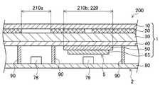
図10は、本実施形態にかかるスイッチ装置200の操作部分の一部を示す概略説明図である。図11は、図10のYY断面を矢印方向に見た概略断面図である。図10に示したように、本実施形態では、車両300の空調装置のオンオフを操作するためのスイッチ装置を例に採って説明する。なお、本実施形態にかかるスイッチ装置200も、図1に示す空調パネル305に備えられた装置とし得る。
<2-1. Configuration of switch device for vehicle>
FIG. 10 is a schematic explanatory view showing a part of the operation part of theswitch device 200 according to the present embodiment. 11 is a schematic cross-sectional view of the YY cross section of FIG. 10 as viewed in the direction of the arrow. As shown in FIG. 10, in this embodiment, a switch device for operating on / off of the air conditioner of thevehicle 300 will be described as an example. In addition, theswitch apparatus 200 concerning this embodiment can also be used as the apparatus with which the air-conditioning panel 305 shown in FIG. 1 was equipped.

スイッチ装置200は、第1の表示領域210a及び第2の表示領域210bを有する。第1の表示領域210aでは、照明装置2に備えられた光源78から出射される光が透過して、操作者等に視認され得る。また、第2の表示領域210bでは、照明装置2に備えられた光源79から出射される光が透過して、操作者等に視認され得る。また、スイッチ装置200は、タッチ領域220を有する。本実施形態では、タッチ領域220は、空調装置のオンオフ操作を行うためのタッチ領域である。かかるタッチ領域220は、第2の表示領域210bに重なる位置に設けられている。  Theswitch device 200 includes afirst display area 210a and asecond display area 210b. In thefirst display area 210a, light emitted from thelight source 78 provided in theillumination device 2 is transmitted and can be visually recognized by an operator or the like. In thesecond display area 210b, light emitted from thelight source 79 provided in theillumination device 2 is transmitted and can be visually recognized by an operator or the like. In addition, theswitch device 200 has atouch area 220. In the present embodiment, thetouch area 220 is a touch area for performing an on / off operation of the air conditioner. Thetouch area 220 is provided at a position overlapping thesecond display area 210b.

タッチ領域220と重なる第2の表示領域210bは、タッチ領域220の操作項目を表示する文字「A/C」が象られ、タッチ領域220の位置を操作者に示す機能を有する。一方、第1の表示領域210aは、矩形に象られ、操作者にフィードバックを与える機能を有する。第1の表示領域210aでは、タッチ領域220へのタッチ操作に伴って色表示の強弱が変化し得る。  Thesecond display area 210b that overlaps thetouch area 220 is engraved with characters “A / C” that display the operation items of thetouch area 220, and has a function of indicating the position of thetouch area 220 to the operator. On the other hand, thefirst display area 210a is shaped like a rectangle and has a function of giving feedback to the operator. In thefirst display area 210a, the strength of the color display can be changed with the touch operation on thetouch area 220.

意匠パネル1のタッチスイッチ部5は、第2の表示領域210bに対応する位置にのみ設けられる。また、照明装置2において、光源78は、第1の表示領域210aに対応する位置に設けられ、光源79は、第2の表示領域210bに対応する位置に設けられている。各光源78,79から出射される光の色は特に限定されるものではなく、意匠性等を考慮して、適宜の色を選択し得る。また、光源78,79の数は、それぞれの表示領域の面積に応じて、適宜選択し得る。光源79の光量を制御しない場合には、光源79は、蛍光管等の光源であってもよい。  Thetouch switch unit 5 of thedesign panel 1 is provided only at a position corresponding to thesecond display area 210b. In theillumination device 2, thelight source 78 is provided at a position corresponding to thefirst display area 210a, and thelight source 79 is provided at a position corresponding to thesecond display area 210b. The color of the light emitted from each of thelight sources 78 and 79 is not particularly limited, and an appropriate color can be selected in consideration of design and the like. Further, the number of thelight sources 78 and 79 can be appropriately selected according to the area of each display region. When the light amount of thelight source 79 is not controlled, thelight source 79 may be a light source such as a fluorescent tube.

また、照明装置2の遮光壁90は、第1の表示領域210a及び第2の表示領域210bそれぞれに対応する領域の外周を取り囲むように配置される。したがって、光源78,79から出射される光は、それぞれ第1の表示領域210a又は第2の表示領域210b以外の表示領域に進入しないように遮られる。  Further, thelight shielding wall 90 of thelighting device 2 is disposed so as to surround the outer periphery of the area corresponding to each of thefirst display area 210a and thesecond display area 210b. Therefore, the light emitted from thelight sources 78 and 79 is blocked so as not to enter the display area other than thefirst display area 210a or thesecond display area 210b.

ここまでに説明した点以外の各構成については、第1の実施の形態にかかるスイッチ装置100と同様の構成とし得る。また、本実施形態にかかるスイッチ装置200のブロック図は、図4に示した第1の実施の形態にかかるスイッチ装置100のブロック図によって示される。すなわち、スイッチ装置200は、タッチ検出回路152、光源駆動回路154及び光源制御部150を備える。このうち、光源制御部150によって行われる照明フィードバック動作が、第1の実施の形態にかかるスイッチ装置100の照明フィードバック動作と異なっている。  About each structure except the point demonstrated so far, it can be set as the structure similar to theswitch apparatus 100 concerning 1st Embodiment. The block diagram of theswitch device 200 according to the present embodiment is shown by the block diagram of theswitch device 100 according to the first embodiment shown in FIG. That is, theswitch device 200 includes atouch detection circuit 152, a lightsource drive circuit 154, and a lightsource control unit 150. Among these, the illumination feedback operation performed by the lightsource control unit 150 is different from the illumination feedback operation of theswitch device 100 according to the first embodiment.

<2−2.照明フィードバック動作>
以上、本実施形態にかかるスイッチ装置200の構成例について説明した。かかるスイッチ装置200をタッチ操作した際の照明フィードバック動作の一例について以下説明する。
<2-2. Lighting feedback operation>
The configuration example of theswitch device 200 according to the present embodiment has been described above. An example of an illumination feedback operation when theswitch device 200 is touched will be described below.

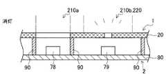
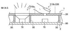
図12〜図14は、本実施形態にかかるスイッチ装置200におけるタッチ操作時の照明フィードバック動作の一例を示す説明図である。図12〜図14は、スイッチ装置200における第1の表示領域210a及び第2の表示領域210bで視認される色表示を概念的に示す説明図である。図12〜図14では、簡略化されたスイッチ装置200の概略断面図が示されている。かかる断面図において、意匠パネル1は1枚の板状に示されており、タッチスイッチ部5等の図示は省略されている。  12-14 is explanatory drawing which shows an example of the illumination feedback operation | movement at the time of touch operation in theswitch apparatus 200 concerning this embodiment. 12-14 is explanatory drawing which shows notionally the color display visually recognized in the1st display area 210a in theswitch apparatus 200, and the2nd display area 210b. In FIGS. 12-14, the schematic sectional drawing of thesimplified switch apparatus 200 is shown. In the cross-sectional view, thedesign panel 1 is shown as a single plate, and the illustration of thetouch switch unit 5 and the like is omitted.

また、図12は、車両300のキースイッチがオンにされた状態を示す。かかる図12の状態では、タッチ操作は行われておらず、また、空調装置はオフにされている。図13は、空調装置を作動させるために、タッチ領域220へのタッチ操作が行われている状態を示す。図14は、タッチ操作が行われた後の、空調装置の作動中の状態を示す。  FIG. 12 shows a state where the key switch of thevehicle 300 is turned on. In the state of FIG. 12, the touch operation is not performed, and the air conditioner is turned off. FIG. 13 shows a state where a touch operation on thetouch area 220 is performed in order to operate the air conditioner. FIG. 14 shows a state where the air conditioner is in operation after the touch operation is performed.

タッチ領域220でもある第2の表示領域210bに関し、図12〜図14に示したように、車両300のキースイッチがオンにされた状態において、第2の表示領域210bに対応する位置に設けられた光源79は点灯状態で維持される。光源79から出射される光の光量は、タッチ操作によっては変化しない。ただし、例えば、車両300のヘッドランプの点灯に連動して、光源79の光量が低下するようにされてもよい。  Thesecond display area 210b which is also thetouch area 220 is provided at a position corresponding to thesecond display area 210b when the key switch of thevehicle 300 is turned on as shown in FIGS. Thelight source 79 is maintained in a lighting state. The amount of light emitted from thelight source 79 does not change depending on the touch operation. However, for example, the light amount of thelight source 79 may be decreased in conjunction with the lighting of the headlamp of thevehicle 300.

照明フィードバックを与える第1の表示領域210aに関し、図12に示したように、空調装置が停止している状態では、光源78は消灯している。この状態では、ブラックアウト仕様により、第1の表示領域210aは表面から視認されにくくなっており、意匠性が高められている。ここで、空調装置を作動させるために、操作者がタッチ領域220へのタッチ操作を行うと、図13に示すように、光源78が点灯する。  With respect to thefirst display area 210a that provides illumination feedback, as shown in FIG. 12, thelight source 78 is turned off when the air conditioner is stopped. In this state, due to the blackout specification, thefirst display area 210a is less visible from the surface, and the design is improved. Here, when the operator performs a touch operation on thetouch area 220 to operate the air conditioner, thelight source 78 is turned on as shown in FIG.

このとき、光源78は、比較的大きい光量で点灯され、第1の表示領域210aでは色表示が強調される。例えば、光源制御部150は、光源78の駆動デューティ比又は光源78への供給電流を比較的大きくすることによって、光源78を比較的大きい光量で点灯し得る。これにより、操作者は、空調装置を作動させる操作を行っている実感を得ることができ、操作感が向上する。  At this time, thelight source 78 is turned on with a relatively large amount of light, and the color display is emphasized in thefirst display area 210a. For example, the lightsource control unit 150 can turn on thelight source 78 with a relatively large amount of light by relatively increasing the drive duty ratio of thelight source 78 or the current supplied to thelight source 78. Thereby, the operator can obtain a feeling of performing an operation for operating the air conditioner, and the feeling of operation is improved.

タッチ操作が行われた後は、図14に示すように、光源78は、タッチ操作時の光量よりも小さい光量で点灯され、第1の表示領域210aでは、相対的に弱い色表示がされた状態で維持される。例えば、光源制御部150は、光源78の駆動デューティ比又は光源78への供給電流を減少させることによって、光源78を比較的小さい光量で点灯し得る。これにより、操作者等は、空調装置が作動中であることを認識し得る。  After the touch operation is performed, as shown in FIG. 14, thelight source 78 is turned on with a light amount smaller than the light amount at the time of the touch operation, and a relatively weak color is displayed in thefirst display area 210a. Maintained in a state. For example, thelight source controller 150 can turn on thelight source 78 with a relatively small amount of light by reducing the drive duty ratio of thelight source 78 or the current supplied to thelight source 78. Thereby, an operator etc. can recognize that the air conditioner is operating.

空調装置の作動を停止する際にも同様に、図13に示すように、タッチ領域220へのタッチ操作に伴って、光源78から出射される光の光量が増加し、第1の表示領域210aの色表示が強調される。これにより、操作者は、空調装置を停止させる操作を行っている実感を得ることができ、操作感が向上する。タッチ操作が行われた後は、図12に示すように、光源78は消灯する。これにより、操作者等は、空調装置が停止中であることを認識し得る。  Similarly, when the operation of the air conditioner is stopped, as shown in FIG. 13, the amount of light emitted from thelight source 78 increases in accordance with the touch operation on thetouch area 220, and thefirst display area 210a. The color display of is highlighted. Thereby, the operator can obtain a feeling of performing the operation of stopping the air conditioner, and the feeling of operation is improved. After the touch operation is performed, thelight source 78 is turned off as shown in FIG. Thereby, the operator or the like can recognize that the air conditioner is stopped.

<2−3.効果>
以上説明したように、第2の実施の形態にかかるスイッチ装置200は、タッチ領域220へのタッチ操作が行われたときに、第1の表示領域210aに対応する位置に設けられた光源78が、タッチ操作が行われていない状態に比べて大きい光量で点灯される。これにより、操作者によるタッチ操作時に、適時に照明フィードバックが与えられるため、操作者は、自身が操作を行っていることを容易に認識することができる。このようにして、スイッチ装置200は、操作感を向上させることができる。
<2-3. Effect>
As described above, theswitch device 200 according to the second embodiment has thelight source 78 provided at the position corresponding to thefirst display area 210a when the touch operation on thetouch area 220 is performed. The light is turned on with a larger amount of light than when no touch operation is performed. Thereby, since illumination feedback is given in a timely manner when the operator performs a touch operation, the operator can easily recognize that he is performing the operation. In this way, theswitch device 200 can improve the operational feeling.

また、第2の実施の形態にかかるスイッチ装置200は、第1の表示領域210aにおける色表示の強弱による照明フィードバック動作を行うものであり、意匠性を向上させることもできる。  Further, theswitch device 200 according to the second embodiment performs an illumination feedback operation based on the intensity of color display in thefirst display area 210a, and can also improve the design.

なお、第2の実施の形態にかかるスイッチ装置200において、第1の表示領域210aに対応する位置に複数の光源が設けられる場合には、点灯する光源の数を変化させることによって、第1の表示領域210aでの色表示の明るさを変化させてもよい。この場合、点灯あるいは消灯する光源から出射される光の光量が変化することとなる。  In theswitch device 200 according to the second embodiment, when a plurality of light sources are provided at positions corresponding to thefirst display area 210a, the first light source is changed by changing the number of light sources to be turned on. The brightness of the color display in thedisplay area 210a may be changed. In this case, the amount of light emitted from the light source that is turned on or off changes.

以上、添付図面を参照しながら本発明の好適な実施形態について詳細に説明したが、本発明はかかる例に限定されない。本発明の属する技術の分野における通常の知識を有する者であれば、特許請求の範囲に記載された技術的思想の範疇内において、各種の変更例または修正例に想到し得ることは明らかであり、これらについても、当然に本発明の技術的範囲に属するものと了解される。  The preferred embodiments of the present invention have been described in detail above with reference to the accompanying drawings, but the present invention is not limited to such examples. It is obvious that a person having ordinary knowledge in the technical field to which the present invention pertains can come up with various changes or modifications within the scope of the technical idea described in the claims. Of course, it is understood that these also belong to the technical scope of the present invention.

1 意匠パネル
2 照明装置
5 タッチスイッチ部
10 表面層
20 遮光層
30 成形樹脂板
40 拡散フィルム
50 フィルム基板
60A,60B タッチ検出電極
70a,70b,70c 青色光源
75a,75b,75c 赤色光源
78,79 光源
80 基板
90 遮光壁
100,100A,200 車両用のスイッチ装置
110 表示領域
120a 第1のタッチ領域
120b 第2のタッチ領域
150 光源制御部
152 タッチ検出回路
154 光源駆動回路
210a 第1の表示領域
210b 第2の表示領域
220 タッチ領域
300 車両
302 インストルメントパネル
303 センタクラスタ
304 ディスプレイ装置
305 空調パネル
DESCRIPTION OFSYMBOLS 1Design panel 2Illuminating device 5Touch switch part 10Surface layer 20Light shielding layer 30Molding resin board 40Diffusion film 50Film substrate 60A, 60BTouch detection electrode 70a, 70b, 70c Bluelight source 75a, 75b, 75c Redlight source 78, 79 Light source DESCRIPTION OFSYMBOLS 80 Board |substrate 90 Light-shielding wall 100,100A, 200Switch apparatus 110 forvehicles 110Display area 120a1st touch area 120b2nd touch area 150 Lightsource control part 152Touch detection circuit 154 Lightsource drive circuit 210a1st display area 210b1st display area 2display area 220touch area 300vehicle 302instrument panel 303center cluster 304display device 305 air conditioning panel

Claims (7)

Translated fromJapanese
光源と、
前記光源から出射される出射光が透過して表示される表示領域と、
タッチ領域へのタッチ操作により静電容量が変化するタッチスイッチ部と、
前記静電容量の変化に基づき前記タッチ操作を検出するタッチ検出部と、
前記タッチ操作に基づいて前記出射光の光量を変化させる光源制御部と、
を備える、車両用スイッチ装置。
A light source;
A display area where the emitted light emitted from the light source is transmitted and displayed;
A touch switch unit whose capacitance changes by a touch operation on the touch area; and
A touch detection unit that detects the touch operation based on a change in the capacitance;
A light source controller that changes the amount of the emitted light based on the touch operation;
A vehicle switch device.
前記光源は複数の光源を含み、
前記タッチ領域は、所定の車載機器を操作するための第1のタッチ領域及び第2のタッチ領域を有し、
前記光源制御部は、前記タッチ操作が行われたタッチ領域に対応して、異なる前記光源の前記出射光の光量を変化させる、請求項1に記載の車両用スイッチ装置。
The light source includes a plurality of light sources,
The touch area includes a first touch area and a second touch area for operating a predetermined in-vehicle device,
2. The vehicle switch device according to claim 1, wherein the light source control unit changes a light amount of the emitted light of a different light source corresponding to a touch area where the touch operation is performed.
前記複数の光源は、前記第1のタッチ領域及び前記第2のタッチ領域の配置に対応するように配列され、
前記光源制御部は、前記タッチ操作が行われたタッチ領域に対応する位置の前記光源の前記出射光の光量を増加させる、請求項2に記載の車両用スイッチ装置。
The plurality of light sources are arranged to correspond to the arrangement of the first touch area and the second touch area,
The vehicle switch device according to claim 2, wherein the light source control unit increases a light amount of the emitted light of the light source at a position corresponding to a touch area where the touch operation is performed.
前記光源制御部は、前記タッチ操作が行われないタッチ領域に対応する位置の前記光源の前記出射光の光量を減少させる、請求項3に記載の車両用スイッチ装置。  4. The vehicle switch device according to claim 3, wherein the light source control unit reduces a light amount of the emitted light of the light source at a position corresponding to a touch area where the touch operation is not performed. 前記光源制御部は、前記光源の駆動デューティ比、前記光源への供給電流、及び点灯させる前記光源の数のうちの少なくとも一つを変化させることにより、前記出射光の光量を変化させる、請求項1〜4のいずれか1項に記載の車両用スイッチ装置。  The light source control unit changes the light amount of the emitted light by changing at least one of a drive duty ratio of the light source, a supply current to the light source, and the number of the light sources to be lit. The switch device for vehicles given in any 1 paragraph of 1-4. 前記光源は、互いに色が異なる複数の光源を含む、請求項1〜5のいずれか1項に記載の車両用スイッチ装置。  The vehicle switch device according to any one of claims 1 to 5, wherein the light source includes a plurality of light sources having different colors. 前記表示領域と前記タッチ領域とが互いに重なる、請求項1〜6のいずれか1項に記載の車両用スイッチ装置。
The vehicle switch device according to claim 1, wherein the display area and the touch area overlap each other.
JP2014245742A2014-12-042014-12-04Switch device for vehiclesPendingJP2016110775A (en)

Priority Applications (1)

Application NumberPriority DateFiling DateTitle
JP2014245742AJP2016110775A (en)2014-12-042014-12-04Switch device for vehicles

Applications Claiming Priority (1)

Application NumberPriority DateFiling DateTitle
JP2014245742AJP2016110775A (en)2014-12-042014-12-04Switch device for vehicles

Publications (1)

Publication NumberPublication Date
JP2016110775Atrue JP2016110775A (en)2016-06-20

Family

ID=56124581

Family Applications (1)

Application NumberTitlePriority DateFiling Date
JP2014245742APendingJP2016110775A (en)2014-12-042014-12-04Switch device for vehicles

Country Status (1)

CountryLink
JP (1)JP2016110775A (en)

Cited By (8)

* Cited by examiner, † Cited by third party
Publication numberPriority datePublication dateAssigneeTitle
JP2019001186A (en)*2017-06-122019-01-10カルソニックカンセイ株式会社Translucent skin material, and method for manufacturing the same
JP2019160431A (en)*2018-03-072019-09-19株式会社オカムラSurface component
WO2020116357A1 (en)*2018-12-072020-06-11株式会社ソニー・インタラクティブエンタテインメントInput device
WO2020179785A1 (en)*2019-03-062020-09-10日本精機株式会社Vehicle display device
WO2020262484A1 (en)2019-06-272020-12-30株式会社JvcケンウッドDisplay device, electronic device, and assembling method
JP2021099943A (en)*2019-12-232021-07-01パナソニックIpマネジメント株式会社Input device
WO2022054359A1 (en)*2020-09-102022-03-17ダイキン工業株式会社Display device and air conditioner
JP2022095758A (en)*2016-09-232022-06-28アップル インコーポレイテッドUser interface structure

Citations (3)

* Cited by examiner, † Cited by third party
Publication numberPriority datePublication dateAssigneeTitle
JP2007157157A (en)*2005-12-022007-06-21Lg Electronics Inc Mobile terminal and operation method thereof
JP2008041536A (en)*2006-08-092008-02-21Matsushita Electric Ind Co Ltd Input device
JP2011096369A (en)*2009-10-272011-05-12Fujikura LtdCapacitance switch device

Patent Citations (3)

* Cited by examiner, † Cited by third party
Publication numberPriority datePublication dateAssigneeTitle
JP2007157157A (en)*2005-12-022007-06-21Lg Electronics Inc Mobile terminal and operation method thereof
JP2008041536A (en)*2006-08-092008-02-21Matsushita Electric Ind Co Ltd Input device
JP2011096369A (en)*2009-10-272011-05-12Fujikura LtdCapacitance switch device

Cited By (15)

* Cited by examiner, † Cited by third party
Publication numberPriority datePublication dateAssigneeTitle
JP7408712B2 (en)2016-09-232024-01-05アップル インコーポレイテッド User interface structure
JP2022095758A (en)*2016-09-232022-06-28アップル インコーポレイテッドUser interface structure
JP2019001186A (en)*2017-06-122019-01-10カルソニックカンセイ株式会社Translucent skin material, and method for manufacturing the same
JP2019160431A (en)*2018-03-072019-09-19株式会社オカムラSurface component
JP7080677B2 (en)2018-03-072022-06-06株式会社オカムラ Surface components
JPWO2020116357A1 (en)*2018-12-072021-10-21株式会社ソニー・インタラクティブエンタテインメント Input device
US11554319B2 (en)2018-12-072023-01-17Sony Interactive Entertainment Inc.Input device
JP7244543B2 (en)2018-12-072023-03-22株式会社ソニー・インタラクティブエンタテインメント input device
WO2020116357A1 (en)*2018-12-072020-06-11株式会社ソニー・インタラクティブエンタテインメントInput device
WO2020179785A1 (en)*2019-03-062020-09-10日本精機株式会社Vehicle display device
WO2020262484A1 (en)2019-06-272020-12-30株式会社JvcケンウッドDisplay device, electronic device, and assembling method
US11937383B2 (en)2019-06-272024-03-19Jvckenwood CorporationDisplay device, electronic device, and assembling method
JP2021099943A (en)*2019-12-232021-07-01パナソニックIpマネジメント株式会社Input device
JP7336676B2 (en)2019-12-232023-09-01パナソニックIpマネジメント株式会社 input device
WO2022054359A1 (en)*2020-09-102022-03-17ダイキン工業株式会社Display device and air conditioner

Similar Documents

PublicationPublication DateTitle
JP2016110775A (en)Switch device for vehicles
JP5307227B2 (en) Touch-type operation input device and electronic device including the same
KR102049649B1 (en)Finger-operated control bar, and use of said control bar
CN210162053U (en)Input keypad assembly on a vehicle
US20170351422A1 (en)Transportation means, user interface and method for overlapping the display of display contents over two display devices
JP2012523671A (en) Integrated touch sensor electrode and backlight mask
JP2012501478A (en) 3D graphics that change appearance
CN113557158B (en)Device and method for outputting parameter values in a vehicle
TW201310282A (en)Illuminating keyboard
US10596906B2 (en)Finger strip and use of said finger strip
JP4713210B2 (en) Capacitance type switch device
JP2006128019A (en) Capacitance type switch device
CN110341590B (en) Lighting device for illuminating the interior of a vehicle
JP2010225480A (en)Switch module
US20170349046A1 (en)Infotainment system, means of transportation, and device for operating an infotainment system of a means of transportation
CN112930276A (en)Surface-light decorative element with optically activatable symbol body
JP2012018465A (en)Operation input device and method of controlling the same
US12083884B2 (en)Vehicle component, vehicle and method for communication between a vehicle and a user
CN116857618A (en)Atmosphere lamp, control method and vehicle
JP6740001B2 (en) Lighting equipment
JP2014086344A (en)Touch switch device
KR20140120534A (en)Transparent touch screen and doorlock having the touch screen
JP2013016437A (en)Operating device for vehicle
CN111124168B (en) Metal touch module, electronic device and control method thereof
JP6852650B2 (en) Vehicle interior parts

Legal Events

DateCodeTitleDescription
A621Written request for application examination

Free format text:JAPANESE INTERMEDIATE CODE: A621

Effective date:20170524

A977Report on retrieval

Free format text:JAPANESE INTERMEDIATE CODE: A971007

Effective date:20171222

A131Notification of reasons for refusal

Free format text:JAPANESE INTERMEDIATE CODE: A131

Effective date:20180109

A02Decision of refusal

Free format text:JAPANESE INTERMEDIATE CODE: A02

Effective date:20180703


[8]ページ先頭

©2009-2025 Movatter.jp