JP2016104270A - Dialysis system comprising downloaded prescription entries - Google Patents
Dialysis system comprising downloaded prescription entriesDownload PDFInfo
- Publication number
- JP2016104270A JP2016104270AJP2016037500AJP2016037500AJP2016104270AJP 2016104270 AJP2016104270 AJP 2016104270AJP 2016037500 AJP2016037500 AJP 2016037500AJP 2016037500 AJP2016037500 AJP 2016037500AJP 2016104270 AJP2016104270 AJP 2016104270A
- Authority
- JP
- Japan
- Prior art keywords
- fluid
- dialysate
- pump
- dialysis
- blood
- Prior art date
- Legal status (The legal status is an assumption and is not a legal conclusion. Google has not performed a legal analysis and makes no representation as to the accuracy of the status listed.)
- Withdrawn
Links
Images


Classifications
- A—HUMAN NECESSITIES
- A61—MEDICAL OR VETERINARY SCIENCE; HYGIENE
- A61M—DEVICES FOR INTRODUCING MEDIA INTO, OR ONTO, THE BODY; DEVICES FOR TRANSDUCING BODY MEDIA OR FOR TAKING MEDIA FROM THE BODY; DEVICES FOR PRODUCING OR ENDING SLEEP OR STUPOR
- A61M1/00—Suction or pumping devices for medical purposes; Devices for carrying-off, for treatment of, or for carrying-over, body-liquids; Drainage systems
- A61M1/34—Filtering material out of the blood by passing it through a membrane, i.e. hemofiltration or diafiltration
- A61M1/3413—Diafiltration
- A61M1/3417—Diafiltration using distinct filters for dialysis and ultra-filtration
- A—HUMAN NECESSITIES
- A61—MEDICAL OR VETERINARY SCIENCE; HYGIENE
- A61M—DEVICES FOR INTRODUCING MEDIA INTO, OR ONTO, THE BODY; DEVICES FOR TRANSDUCING BODY MEDIA OR FOR TAKING MEDIA FROM THE BODY; DEVICES FOR PRODUCING OR ENDING SLEEP OR STUPOR
- A61M1/00—Suction or pumping devices for medical purposes; Devices for carrying-off, for treatment of, or for carrying-over, body-liquids; Drainage systems
- A61M1/36—Other treatment of blood in a by-pass of the natural circulatory system, e.g. temperature adaptation, irradiation ; Extra-corporeal blood circuits
- A61M1/3621—Extra-corporeal blood circuits
- A—HUMAN NECESSITIES
- A61—MEDICAL OR VETERINARY SCIENCE; HYGIENE
- A61M—DEVICES FOR INTRODUCING MEDIA INTO, OR ONTO, THE BODY; DEVICES FOR TRANSDUCING BODY MEDIA OR FOR TAKING MEDIA FROM THE BODY; DEVICES FOR PRODUCING OR ENDING SLEEP OR STUPOR
- A61M1/00—Suction or pumping devices for medical purposes; Devices for carrying-off, for treatment of, or for carrying-over, body-liquids; Drainage systems
- A61M1/14—Dialysis systems; Artificial kidneys; Blood oxygenators ; Reciprocating systems for treatment of body fluids, e.g. single needle systems for hemofiltration or pheresis
- A61M1/15—Dialysis systems; Artificial kidneys; Blood oxygenators ; Reciprocating systems for treatment of body fluids, e.g. single needle systems for hemofiltration or pheresis with a cassette forming partially or totally the flow circuit for the treating fluid, e.g. the dialysate fluid circuit or the treating gas circuit
- A61M1/153—Dialysis systems; Artificial kidneys; Blood oxygenators ; Reciprocating systems for treatment of body fluids, e.g. single needle systems for hemofiltration or pheresis with a cassette forming partially or totally the flow circuit for the treating fluid, e.g. the dialysate fluid circuit or the treating gas circuit the cassette being adapted for heating or cooling the treating fluid, e.g. the dialysate or the treating gas
- A—HUMAN NECESSITIES
- A61—MEDICAL OR VETERINARY SCIENCE; HYGIENE
- A61M—DEVICES FOR INTRODUCING MEDIA INTO, OR ONTO, THE BODY; DEVICES FOR TRANSDUCING BODY MEDIA OR FOR TAKING MEDIA FROM THE BODY; DEVICES FOR PRODUCING OR ENDING SLEEP OR STUPOR
- A61M1/00—Suction or pumping devices for medical purposes; Devices for carrying-off, for treatment of, or for carrying-over, body-liquids; Drainage systems
- A61M1/14—Dialysis systems; Artificial kidneys; Blood oxygenators ; Reciprocating systems for treatment of body fluids, e.g. single needle systems for hemofiltration or pheresis
- A61M1/15—Dialysis systems; Artificial kidneys; Blood oxygenators ; Reciprocating systems for treatment of body fluids, e.g. single needle systems for hemofiltration or pheresis with a cassette forming partially or totally the flow circuit for the treating fluid, e.g. the dialysate fluid circuit or the treating gas circuit
- A61M1/154—Dialysis systems; Artificial kidneys; Blood oxygenators ; Reciprocating systems for treatment of body fluids, e.g. single needle systems for hemofiltration or pheresis with a cassette forming partially or totally the flow circuit for the treating fluid, e.g. the dialysate fluid circuit or the treating gas circuit with sensing means or components thereof
- A—HUMAN NECESSITIES
- A61—MEDICAL OR VETERINARY SCIENCE; HYGIENE
- A61M—DEVICES FOR INTRODUCING MEDIA INTO, OR ONTO, THE BODY; DEVICES FOR TRANSDUCING BODY MEDIA OR FOR TAKING MEDIA FROM THE BODY; DEVICES FOR PRODUCING OR ENDING SLEEP OR STUPOR
- A61M1/00—Suction or pumping devices for medical purposes; Devices for carrying-off, for treatment of, or for carrying-over, body-liquids; Drainage systems
- A61M1/14—Dialysis systems; Artificial kidneys; Blood oxygenators ; Reciprocating systems for treatment of body fluids, e.g. single needle systems for hemofiltration or pheresis
- A61M1/15—Dialysis systems; Artificial kidneys; Blood oxygenators ; Reciprocating systems for treatment of body fluids, e.g. single needle systems for hemofiltration or pheresis with a cassette forming partially or totally the flow circuit for the treating fluid, e.g. the dialysate fluid circuit or the treating gas circuit
- A61M1/155—Dialysis systems; Artificial kidneys; Blood oxygenators ; Reciprocating systems for treatment of body fluids, e.g. single needle systems for hemofiltration or pheresis with a cassette forming partially or totally the flow circuit for the treating fluid, e.g. the dialysate fluid circuit or the treating gas circuit with treatment-fluid pumping means or components thereof
- A—HUMAN NECESSITIES
- A61—MEDICAL OR VETERINARY SCIENCE; HYGIENE
- A61M—DEVICES FOR INTRODUCING MEDIA INTO, OR ONTO, THE BODY; DEVICES FOR TRANSDUCING BODY MEDIA OR FOR TAKING MEDIA FROM THE BODY; DEVICES FOR PRODUCING OR ENDING SLEEP OR STUPOR
- A61M1/00—Suction or pumping devices for medical purposes; Devices for carrying-off, for treatment of, or for carrying-over, body-liquids; Drainage systems
- A61M1/14—Dialysis systems; Artificial kidneys; Blood oxygenators ; Reciprocating systems for treatment of body fluids, e.g. single needle systems for hemofiltration or pheresis
- A61M1/15—Dialysis systems; Artificial kidneys; Blood oxygenators ; Reciprocating systems for treatment of body fluids, e.g. single needle systems for hemofiltration or pheresis with a cassette forming partially or totally the flow circuit for the treating fluid, e.g. the dialysate fluid circuit or the treating gas circuit
- A61M1/156—Constructional details of the cassette, e.g. specific details on material or shape
- A61M1/1561—Constructional details of the cassette, e.g. specific details on material or shape at least one cassette surface or portion thereof being flexible, e.g. the cassette having a rigid base portion with preformed channels and being covered with a foil
- A—HUMAN NECESSITIES
- A61—MEDICAL OR VETERINARY SCIENCE; HYGIENE
- A61M—DEVICES FOR INTRODUCING MEDIA INTO, OR ONTO, THE BODY; DEVICES FOR TRANSDUCING BODY MEDIA OR FOR TAKING MEDIA FROM THE BODY; DEVICES FOR PRODUCING OR ENDING SLEEP OR STUPOR
- A61M1/00—Suction or pumping devices for medical purposes; Devices for carrying-off, for treatment of, or for carrying-over, body-liquids; Drainage systems
- A61M1/14—Dialysis systems; Artificial kidneys; Blood oxygenators ; Reciprocating systems for treatment of body fluids, e.g. single needle systems for hemofiltration or pheresis
- A61M1/15—Dialysis systems; Artificial kidneys; Blood oxygenators ; Reciprocating systems for treatment of body fluids, e.g. single needle systems for hemofiltration or pheresis with a cassette forming partially or totally the flow circuit for the treating fluid, e.g. the dialysate fluid circuit or the treating gas circuit
- A61M1/156—Constructional details of the cassette, e.g. specific details on material or shape
- A61M1/1562—Details of incorporated reservoirs
- A61M1/15625—Details of incorporated reservoirs the reservoirs acting as balance chambers
- A—HUMAN NECESSITIES
- A61—MEDICAL OR VETERINARY SCIENCE; HYGIENE
- A61M—DEVICES FOR INTRODUCING MEDIA INTO, OR ONTO, THE BODY; DEVICES FOR TRANSDUCING BODY MEDIA OR FOR TAKING MEDIA FROM THE BODY; DEVICES FOR PRODUCING OR ENDING SLEEP OR STUPOR
- A61M1/00—Suction or pumping devices for medical purposes; Devices for carrying-off, for treatment of, or for carrying-over, body-liquids; Drainage systems
- A61M1/14—Dialysis systems; Artificial kidneys; Blood oxygenators ; Reciprocating systems for treatment of body fluids, e.g. single needle systems for hemofiltration or pheresis
- A61M1/15—Dialysis systems; Artificial kidneys; Blood oxygenators ; Reciprocating systems for treatment of body fluids, e.g. single needle systems for hemofiltration or pheresis with a cassette forming partially or totally the flow circuit for the treating fluid, e.g. the dialysate fluid circuit or the treating gas circuit
- A61M1/156—Constructional details of the cassette, e.g. specific details on material or shape
- A61M1/1563—Details of incorporated filters
- A—HUMAN NECESSITIES
- A61—MEDICAL OR VETERINARY SCIENCE; HYGIENE
- A61M—DEVICES FOR INTRODUCING MEDIA INTO, OR ONTO, THE BODY; DEVICES FOR TRANSDUCING BODY MEDIA OR FOR TAKING MEDIA FROM THE BODY; DEVICES FOR PRODUCING OR ENDING SLEEP OR STUPOR
- A61M1/00—Suction or pumping devices for medical purposes; Devices for carrying-off, for treatment of, or for carrying-over, body-liquids; Drainage systems
- A61M1/14—Dialysis systems; Artificial kidneys; Blood oxygenators ; Reciprocating systems for treatment of body fluids, e.g. single needle systems for hemofiltration or pheresis
- A61M1/15—Dialysis systems; Artificial kidneys; Blood oxygenators ; Reciprocating systems for treatment of body fluids, e.g. single needle systems for hemofiltration or pheresis with a cassette forming partially or totally the flow circuit for the treating fluid, e.g. the dialysate fluid circuit or the treating gas circuit
- A61M1/156—Constructional details of the cassette, e.g. specific details on material or shape
- A61M1/1565—Details of valves
- A—HUMAN NECESSITIES
- A61—MEDICAL OR VETERINARY SCIENCE; HYGIENE
- A61M—DEVICES FOR INTRODUCING MEDIA INTO, OR ONTO, THE BODY; DEVICES FOR TRANSDUCING BODY MEDIA OR FOR TAKING MEDIA FROM THE BODY; DEVICES FOR PRODUCING OR ENDING SLEEP OR STUPOR
- A61M1/00—Suction or pumping devices for medical purposes; Devices for carrying-off, for treatment of, or for carrying-over, body-liquids; Drainage systems
- A61M1/14—Dialysis systems; Artificial kidneys; Blood oxygenators ; Reciprocating systems for treatment of body fluids, e.g. single needle systems for hemofiltration or pheresis
- A61M1/16—Dialysis systems; Artificial kidneys; Blood oxygenators ; Reciprocating systems for treatment of body fluids, e.g. single needle systems for hemofiltration or pheresis with membranes
- A61M1/1601—Control or regulation
- A61M1/1603—Regulation parameters
- A61M1/1605—Physical characteristics of the dialysate fluid
- A61M1/1607—Physical characteristics of the dialysate fluid before use, i.e. upstream of dialyser
- A—HUMAN NECESSITIES
- A61—MEDICAL OR VETERINARY SCIENCE; HYGIENE
- A61M—DEVICES FOR INTRODUCING MEDIA INTO, OR ONTO, THE BODY; DEVICES FOR TRANSDUCING BODY MEDIA OR FOR TAKING MEDIA FROM THE BODY; DEVICES FOR PRODUCING OR ENDING SLEEP OR STUPOR
- A61M1/00—Suction or pumping devices for medical purposes; Devices for carrying-off, for treatment of, or for carrying-over, body-liquids; Drainage systems
- A61M1/14—Dialysis systems; Artificial kidneys; Blood oxygenators ; Reciprocating systems for treatment of body fluids, e.g. single needle systems for hemofiltration or pheresis
- A61M1/16—Dialysis systems; Artificial kidneys; Blood oxygenators ; Reciprocating systems for treatment of body fluids, e.g. single needle systems for hemofiltration or pheresis with membranes
- A61M1/1601—Control or regulation
- A61M1/1613—Profiling or modelling of patient or predicted treatment evolution or outcome
- A—HUMAN NECESSITIES
- A61—MEDICAL OR VETERINARY SCIENCE; HYGIENE
- A61M—DEVICES FOR INTRODUCING MEDIA INTO, OR ONTO, THE BODY; DEVICES FOR TRANSDUCING BODY MEDIA OR FOR TAKING MEDIA FROM THE BODY; DEVICES FOR PRODUCING OR ENDING SLEEP OR STUPOR
- A61M1/00—Suction or pumping devices for medical purposes; Devices for carrying-off, for treatment of, or for carrying-over, body-liquids; Drainage systems
- A61M1/14—Dialysis systems; Artificial kidneys; Blood oxygenators ; Reciprocating systems for treatment of body fluids, e.g. single needle systems for hemofiltration or pheresis
- A61M1/16—Dialysis systems; Artificial kidneys; Blood oxygenators ; Reciprocating systems for treatment of body fluids, e.g. single needle systems for hemofiltration or pheresis with membranes
- A61M1/1621—Constructional aspects thereof
- A61M1/1629—Constructional aspects thereof with integral heat exchanger
- A—HUMAN NECESSITIES
- A61—MEDICAL OR VETERINARY SCIENCE; HYGIENE
- A61M—DEVICES FOR INTRODUCING MEDIA INTO, OR ONTO, THE BODY; DEVICES FOR TRANSDUCING BODY MEDIA OR FOR TAKING MEDIA FROM THE BODY; DEVICES FOR PRODUCING OR ENDING SLEEP OR STUPOR
- A61M1/00—Suction or pumping devices for medical purposes; Devices for carrying-off, for treatment of, or for carrying-over, body-liquids; Drainage systems
- A61M1/14—Dialysis systems; Artificial kidneys; Blood oxygenators ; Reciprocating systems for treatment of body fluids, e.g. single needle systems for hemofiltration or pheresis
- A61M1/16—Dialysis systems; Artificial kidneys; Blood oxygenators ; Reciprocating systems for treatment of body fluids, e.g. single needle systems for hemofiltration or pheresis with membranes
- A61M1/1621—Constructional aspects thereof
- A61M1/1633—Constructional aspects thereof with more than one dialyser unit
- A—HUMAN NECESSITIES
- A61—MEDICAL OR VETERINARY SCIENCE; HYGIENE
- A61M—DEVICES FOR INTRODUCING MEDIA INTO, OR ONTO, THE BODY; DEVICES FOR TRANSDUCING BODY MEDIA OR FOR TAKING MEDIA FROM THE BODY; DEVICES FOR PRODUCING OR ENDING SLEEP OR STUPOR
- A61M1/00—Suction or pumping devices for medical purposes; Devices for carrying-off, for treatment of, or for carrying-over, body-liquids; Drainage systems
- A61M1/14—Dialysis systems; Artificial kidneys; Blood oxygenators ; Reciprocating systems for treatment of body fluids, e.g. single needle systems for hemofiltration or pheresis
- A61M1/16—Dialysis systems; Artificial kidneys; Blood oxygenators ; Reciprocating systems for treatment of body fluids, e.g. single needle systems for hemofiltration or pheresis with membranes
- A61M1/1621—Constructional aspects thereof
- A61M1/1635—Constructional aspects thereof with volume chamber balancing devices between used and fresh dialysis fluid
- A—HUMAN NECESSITIES
- A61—MEDICAL OR VETERINARY SCIENCE; HYGIENE
- A61M—DEVICES FOR INTRODUCING MEDIA INTO, OR ONTO, THE BODY; DEVICES FOR TRANSDUCING BODY MEDIA OR FOR TAKING MEDIA FROM THE BODY; DEVICES FOR PRODUCING OR ENDING SLEEP OR STUPOR
- A61M1/00—Suction or pumping devices for medical purposes; Devices for carrying-off, for treatment of, or for carrying-over, body-liquids; Drainage systems
- A61M1/14—Dialysis systems; Artificial kidneys; Blood oxygenators ; Reciprocating systems for treatment of body fluids, e.g. single needle systems for hemofiltration or pheresis
- A61M1/16—Dialysis systems; Artificial kidneys; Blood oxygenators ; Reciprocating systems for treatment of body fluids, e.g. single needle systems for hemofiltration or pheresis with membranes
- A61M1/1654—Dialysates therefor
- A61M1/1656—Apparatus for preparing dialysates
- A61M1/166—Heating
- A—HUMAN NECESSITIES
- A61—MEDICAL OR VETERINARY SCIENCE; HYGIENE
- A61M—DEVICES FOR INTRODUCING MEDIA INTO, OR ONTO, THE BODY; DEVICES FOR TRANSDUCING BODY MEDIA OR FOR TAKING MEDIA FROM THE BODY; DEVICES FOR PRODUCING OR ENDING SLEEP OR STUPOR
- A61M1/00—Suction or pumping devices for medical purposes; Devices for carrying-off, for treatment of, or for carrying-over, body-liquids; Drainage systems
- A61M1/14—Dialysis systems; Artificial kidneys; Blood oxygenators ; Reciprocating systems for treatment of body fluids, e.g. single needle systems for hemofiltration or pheresis
- A61M1/16—Dialysis systems; Artificial kidneys; Blood oxygenators ; Reciprocating systems for treatment of body fluids, e.g. single needle systems for hemofiltration or pheresis with membranes
- A61M1/1654—Dialysates therefor
- A61M1/1656—Apparatus for preparing dialysates
- A61M1/1668—Details of containers
- A61M1/167—Flexible packaging for solid concentrates
- A—HUMAN NECESSITIES
- A61—MEDICAL OR VETERINARY SCIENCE; HYGIENE
- A61M—DEVICES FOR INTRODUCING MEDIA INTO, OR ONTO, THE BODY; DEVICES FOR TRANSDUCING BODY MEDIA OR FOR TAKING MEDIA FROM THE BODY; DEVICES FOR PRODUCING OR ENDING SLEEP OR STUPOR
- A61M1/00—Suction or pumping devices for medical purposes; Devices for carrying-off, for treatment of, or for carrying-over, body-liquids; Drainage systems
- A61M1/14—Dialysis systems; Artificial kidneys; Blood oxygenators ; Reciprocating systems for treatment of body fluids, e.g. single needle systems for hemofiltration or pheresis
- A61M1/16—Dialysis systems; Artificial kidneys; Blood oxygenators ; Reciprocating systems for treatment of body fluids, e.g. single needle systems for hemofiltration or pheresis with membranes
- A61M1/1654—Dialysates therefor
- A61M1/1656—Apparatus for preparing dialysates
- A61M1/1672—Apparatus for preparing dialysates using membrane filters, e.g. for sterilising the dialysate
- A—HUMAN NECESSITIES
- A61—MEDICAL OR VETERINARY SCIENCE; HYGIENE
- A61M—DEVICES FOR INTRODUCING MEDIA INTO, OR ONTO, THE BODY; DEVICES FOR TRANSDUCING BODY MEDIA OR FOR TAKING MEDIA FROM THE BODY; DEVICES FOR PRODUCING OR ENDING SLEEP OR STUPOR
- A61M1/00—Suction or pumping devices for medical purposes; Devices for carrying-off, for treatment of, or for carrying-over, body-liquids; Drainage systems
- A61M1/14—Dialysis systems; Artificial kidneys; Blood oxygenators ; Reciprocating systems for treatment of body fluids, e.g. single needle systems for hemofiltration or pheresis
- A61M1/16—Dialysis systems; Artificial kidneys; Blood oxygenators ; Reciprocating systems for treatment of body fluids, e.g. single needle systems for hemofiltration or pheresis with membranes
- A61M1/1694—Dialysis systems; Artificial kidneys; Blood oxygenators ; Reciprocating systems for treatment of body fluids, e.g. single needle systems for hemofiltration or pheresis with membranes with recirculating dialysing liquid
- A61M1/1696—Dialysis systems; Artificial kidneys; Blood oxygenators ; Reciprocating systems for treatment of body fluids, e.g. single needle systems for hemofiltration or pheresis with membranes with recirculating dialysing liquid with dialysate regeneration
- A—HUMAN NECESSITIES
- A61—MEDICAL OR VETERINARY SCIENCE; HYGIENE
- A61M—DEVICES FOR INTRODUCING MEDIA INTO, OR ONTO, THE BODY; DEVICES FOR TRANSDUCING BODY MEDIA OR FOR TAKING MEDIA FROM THE BODY; DEVICES FOR PRODUCING OR ENDING SLEEP OR STUPOR
- A61M1/00—Suction or pumping devices for medical purposes; Devices for carrying-off, for treatment of, or for carrying-over, body-liquids; Drainage systems
- A61M1/14—Dialysis systems; Artificial kidneys; Blood oxygenators ; Reciprocating systems for treatment of body fluids, e.g. single needle systems for hemofiltration or pheresis
- A61M1/16—Dialysis systems; Artificial kidneys; Blood oxygenators ; Reciprocating systems for treatment of body fluids, e.g. single needle systems for hemofiltration or pheresis with membranes
- A61M1/26—Dialysis systems; Artificial kidneys; Blood oxygenators ; Reciprocating systems for treatment of body fluids, e.g. single needle systems for hemofiltration or pheresis with membranes and internal elements which are moving
- A61M1/267—Dialysis systems; Artificial kidneys; Blood oxygenators ; Reciprocating systems for treatment of body fluids, e.g. single needle systems for hemofiltration or pheresis with membranes and internal elements which are moving used for pumping
- A—HUMAN NECESSITIES
- A61—MEDICAL OR VETERINARY SCIENCE; HYGIENE
- A61M—DEVICES FOR INTRODUCING MEDIA INTO, OR ONTO, THE BODY; DEVICES FOR TRANSDUCING BODY MEDIA OR FOR TAKING MEDIA FROM THE BODY; DEVICES FOR PRODUCING OR ENDING SLEEP OR STUPOR
- A61M1/00—Suction or pumping devices for medical purposes; Devices for carrying-off, for treatment of, or for carrying-over, body-liquids; Drainage systems
- A61M1/14—Dialysis systems; Artificial kidneys; Blood oxygenators ; Reciprocating systems for treatment of body fluids, e.g. single needle systems for hemofiltration or pheresis
- A61M1/28—Peritoneal dialysis ; Other peritoneal treatment, e.g. oxygenation
- A61M1/288—Priming
- A—HUMAN NECESSITIES
- A61—MEDICAL OR VETERINARY SCIENCE; HYGIENE
- A61M—DEVICES FOR INTRODUCING MEDIA INTO, OR ONTO, THE BODY; DEVICES FOR TRANSDUCING BODY MEDIA OR FOR TAKING MEDIA FROM THE BODY; DEVICES FOR PRODUCING OR ENDING SLEEP OR STUPOR
- A61M1/00—Suction or pumping devices for medical purposes; Devices for carrying-off, for treatment of, or for carrying-over, body-liquids; Drainage systems
- A61M1/34—Filtering material out of the blood by passing it through a membrane, i.e. hemofiltration or diafiltration
- A61M1/3401—Cassettes therefor
- A—HUMAN NECESSITIES
- A61—MEDICAL OR VETERINARY SCIENCE; HYGIENE
- A61M—DEVICES FOR INTRODUCING MEDIA INTO, OR ONTO, THE BODY; DEVICES FOR TRANSDUCING BODY MEDIA OR FOR TAKING MEDIA FROM THE BODY; DEVICES FOR PRODUCING OR ENDING SLEEP OR STUPOR
- A61M1/00—Suction or pumping devices for medical purposes; Devices for carrying-off, for treatment of, or for carrying-over, body-liquids; Drainage systems
- A61M1/34—Filtering material out of the blood by passing it through a membrane, i.e. hemofiltration or diafiltration
- A61M1/3403—Regulation parameters
- A61M1/341—Regulation parameters by measuring the filtrate rate or volume
- A—HUMAN NECESSITIES
- A61—MEDICAL OR VETERINARY SCIENCE; HYGIENE
- A61M—DEVICES FOR INTRODUCING MEDIA INTO, OR ONTO, THE BODY; DEVICES FOR TRANSDUCING BODY MEDIA OR FOR TAKING MEDIA FROM THE BODY; DEVICES FOR PRODUCING OR ENDING SLEEP OR STUPOR
- A61M1/00—Suction or pumping devices for medical purposes; Devices for carrying-off, for treatment of, or for carrying-over, body-liquids; Drainage systems
- A61M1/34—Filtering material out of the blood by passing it through a membrane, i.e. hemofiltration or diafiltration
- A61M1/342—Adding solutions to the blood, e.g. substitution solutions
- A61M1/3424—Substitution fluid path
- A61M1/3427—Substitution fluid path back through the membrane, e.g. by inverted trans-membrane pressure [TMP]
- A—HUMAN NECESSITIES
- A61—MEDICAL OR VETERINARY SCIENCE; HYGIENE
- A61M—DEVICES FOR INTRODUCING MEDIA INTO, OR ONTO, THE BODY; DEVICES FOR TRANSDUCING BODY MEDIA OR FOR TAKING MEDIA FROM THE BODY; DEVICES FOR PRODUCING OR ENDING SLEEP OR STUPOR
- A61M1/00—Suction or pumping devices for medical purposes; Devices for carrying-off, for treatment of, or for carrying-over, body-liquids; Drainage systems
- A61M1/34—Filtering material out of the blood by passing it through a membrane, i.e. hemofiltration or diafiltration
- A61M1/342—Adding solutions to the blood, e.g. substitution solutions
- A61M1/3424—Substitution fluid path
- A61M1/3431—Substitution fluid path upstream of the filter
- A61M1/3434—Substitution fluid path upstream of the filter with pre-dilution and post-dilution
- A—HUMAN NECESSITIES
- A61—MEDICAL OR VETERINARY SCIENCE; HYGIENE
- A61M—DEVICES FOR INTRODUCING MEDIA INTO, OR ONTO, THE BODY; DEVICES FOR TRANSDUCING BODY MEDIA OR FOR TAKING MEDIA FROM THE BODY; DEVICES FOR PRODUCING OR ENDING SLEEP OR STUPOR
- A61M1/00—Suction or pumping devices for medical purposes; Devices for carrying-off, for treatment of, or for carrying-over, body-liquids; Drainage systems
- A61M1/34—Filtering material out of the blood by passing it through a membrane, i.e. hemofiltration or diafiltration
- A61M1/342—Adding solutions to the blood, e.g. substitution solutions
- A61M1/3424—Substitution fluid path
- A61M1/3437—Substitution fluid path downstream of the filter, e.g. post-dilution with filtrate
- A—HUMAN NECESSITIES
- A61—MEDICAL OR VETERINARY SCIENCE; HYGIENE
- A61M—DEVICES FOR INTRODUCING MEDIA INTO, OR ONTO, THE BODY; DEVICES FOR TRANSDUCING BODY MEDIA OR FOR TAKING MEDIA FROM THE BODY; DEVICES FOR PRODUCING OR ENDING SLEEP OR STUPOR
- A61M1/00—Suction or pumping devices for medical purposes; Devices for carrying-off, for treatment of, or for carrying-over, body-liquids; Drainage systems
- A61M1/34—Filtering material out of the blood by passing it through a membrane, i.e. hemofiltration or diafiltration
- A61M1/342—Adding solutions to the blood, e.g. substitution solutions
- A61M1/3441—Substitution rate control as a function of the ultrafiltration rate
- A61M1/3444—Substitution rate control as a function of the ultrafiltration rate in which the collected ultra-filtrate expels an equal volume of substitution fluid from a reservoir
- A—HUMAN NECESSITIES
- A61—MEDICAL OR VETERINARY SCIENCE; HYGIENE
- A61M—DEVICES FOR INTRODUCING MEDIA INTO, OR ONTO, THE BODY; DEVICES FOR TRANSDUCING BODY MEDIA OR FOR TAKING MEDIA FROM THE BODY; DEVICES FOR PRODUCING OR ENDING SLEEP OR STUPOR
- A61M1/00—Suction or pumping devices for medical purposes; Devices for carrying-off, for treatment of, or for carrying-over, body-liquids; Drainage systems
- A61M1/34—Filtering material out of the blood by passing it through a membrane, i.e. hemofiltration or diafiltration
- A61M1/342—Adding solutions to the blood, e.g. substitution solutions
- A61M1/3441—Substitution rate control as a function of the ultrafiltration rate
- A61M1/3451—Substitution rate control as a function of the ultrafiltration rate the difference in weight between both ultra-filtrate and substitution reservoir being used as control signal
- A—HUMAN NECESSITIES
- A61—MEDICAL OR VETERINARY SCIENCE; HYGIENE
- A61M—DEVICES FOR INTRODUCING MEDIA INTO, OR ONTO, THE BODY; DEVICES FOR TRANSDUCING BODY MEDIA OR FOR TAKING MEDIA FROM THE BODY; DEVICES FOR PRODUCING OR ENDING SLEEP OR STUPOR
- A61M1/00—Suction or pumping devices for medical purposes; Devices for carrying-off, for treatment of, or for carrying-over, body-liquids; Drainage systems
- A61M1/34—Filtering material out of the blood by passing it through a membrane, i.e. hemofiltration or diafiltration
- A61M1/342—Adding solutions to the blood, e.g. substitution solutions
- A61M1/3455—Substitution fluids
- A61M1/3458—Substitution fluids having electrolytes not present in the dialysate
- A—HUMAN NECESSITIES
- A61—MEDICAL OR VETERINARY SCIENCE; HYGIENE
- A61M—DEVICES FOR INTRODUCING MEDIA INTO, OR ONTO, THE BODY; DEVICES FOR TRANSDUCING BODY MEDIA OR FOR TAKING MEDIA FROM THE BODY; DEVICES FOR PRODUCING OR ENDING SLEEP OR STUPOR
- A61M1/00—Suction or pumping devices for medical purposes; Devices for carrying-off, for treatment of, or for carrying-over, body-liquids; Drainage systems
- A61M1/34—Filtering material out of the blood by passing it through a membrane, i.e. hemofiltration or diafiltration
- A61M1/342—Adding solutions to the blood, e.g. substitution solutions
- A61M1/3455—Substitution fluids
- A61M1/3465—Substitution fluids using dialysate as substitution fluid
- A—HUMAN NECESSITIES
- A61—MEDICAL OR VETERINARY SCIENCE; HYGIENE
- A61M—DEVICES FOR INTRODUCING MEDIA INTO, OR ONTO, THE BODY; DEVICES FOR TRANSDUCING BODY MEDIA OR FOR TAKING MEDIA FROM THE BODY; DEVICES FOR PRODUCING OR ENDING SLEEP OR STUPOR
- A61M1/00—Suction or pumping devices for medical purposes; Devices for carrying-off, for treatment of, or for carrying-over, body-liquids; Drainage systems
- A61M1/34—Filtering material out of the blood by passing it through a membrane, i.e. hemofiltration or diafiltration
- A61M1/342—Adding solutions to the blood, e.g. substitution solutions
- A61M1/3455—Substitution fluids
- A61M1/3468—Substitution fluids using treated filtrate as substitution fluid
- A—HUMAN NECESSITIES
- A61—MEDICAL OR VETERINARY SCIENCE; HYGIENE
- A61M—DEVICES FOR INTRODUCING MEDIA INTO, OR ONTO, THE BODY; DEVICES FOR TRANSDUCING BODY MEDIA OR FOR TAKING MEDIA FROM THE BODY; DEVICES FOR PRODUCING OR ENDING SLEEP OR STUPOR
- A61M1/00—Suction or pumping devices for medical purposes; Devices for carrying-off, for treatment of, or for carrying-over, body-liquids; Drainage systems
- A61M1/34—Filtering material out of the blood by passing it through a membrane, i.e. hemofiltration or diafiltration
- A61M1/3472—Filtering material out of the blood by passing it through a membrane, i.e. hemofiltration or diafiltration with treatment of the filtrate
- A—HUMAN NECESSITIES
- A61—MEDICAL OR VETERINARY SCIENCE; HYGIENE
- A61M—DEVICES FOR INTRODUCING MEDIA INTO, OR ONTO, THE BODY; DEVICES FOR TRANSDUCING BODY MEDIA OR FOR TAKING MEDIA FROM THE BODY; DEVICES FOR PRODUCING OR ENDING SLEEP OR STUPOR
- A61M1/00—Suction or pumping devices for medical purposes; Devices for carrying-off, for treatment of, or for carrying-over, body-liquids; Drainage systems
- A61M1/36—Other treatment of blood in a by-pass of the natural circulatory system, e.g. temperature adaptation, irradiation ; Extra-corporeal blood circuits
- A61M1/3621—Extra-corporeal blood circuits
- A61M1/3622—Extra-corporeal blood circuits with a cassette forming partially or totally the blood circuit
- A61M1/36224—Extra-corporeal blood circuits with a cassette forming partially or totally the blood circuit with sensing means or components thereof
- A—HUMAN NECESSITIES
- A61—MEDICAL OR VETERINARY SCIENCE; HYGIENE
- A61M—DEVICES FOR INTRODUCING MEDIA INTO, OR ONTO, THE BODY; DEVICES FOR TRANSDUCING BODY MEDIA OR FOR TAKING MEDIA FROM THE BODY; DEVICES FOR PRODUCING OR ENDING SLEEP OR STUPOR
- A61M1/00—Suction or pumping devices for medical purposes; Devices for carrying-off, for treatment of, or for carrying-over, body-liquids; Drainage systems
- A61M1/36—Other treatment of blood in a by-pass of the natural circulatory system, e.g. temperature adaptation, irradiation ; Extra-corporeal blood circuits
- A61M1/3621—Extra-corporeal blood circuits
- A61M1/3622—Extra-corporeal blood circuits with a cassette forming partially or totally the blood circuit
- A61M1/36225—Extra-corporeal blood circuits with a cassette forming partially or totally the blood circuit with blood pumping means or components thereof
- A—HUMAN NECESSITIES
- A61—MEDICAL OR VETERINARY SCIENCE; HYGIENE
- A61M—DEVICES FOR INTRODUCING MEDIA INTO, OR ONTO, THE BODY; DEVICES FOR TRANSDUCING BODY MEDIA OR FOR TAKING MEDIA FROM THE BODY; DEVICES FOR PRODUCING OR ENDING SLEEP OR STUPOR
- A61M1/00—Suction or pumping devices for medical purposes; Devices for carrying-off, for treatment of, or for carrying-over, body-liquids; Drainage systems
- A61M1/36—Other treatment of blood in a by-pass of the natural circulatory system, e.g. temperature adaptation, irradiation ; Extra-corporeal blood circuits
- A61M1/3621—Extra-corporeal blood circuits
- A61M1/3622—Extra-corporeal blood circuits with a cassette forming partially or totally the blood circuit
- A61M1/36226—Constructional details of cassettes, e.g. specific details on material or shape
- A61M1/362261—Constructional details of cassettes, e.g. specific details on material or shape at least one cassette surface or portion thereof being flexible, e.g. the cassette having a rigid base portion with preformed channels and being covered with a foil
- A—HUMAN NECESSITIES
- A61—MEDICAL OR VETERINARY SCIENCE; HYGIENE
- A61M—DEVICES FOR INTRODUCING MEDIA INTO, OR ONTO, THE BODY; DEVICES FOR TRANSDUCING BODY MEDIA OR FOR TAKING MEDIA FROM THE BODY; DEVICES FOR PRODUCING OR ENDING SLEEP OR STUPOR
- A61M1/00—Suction or pumping devices for medical purposes; Devices for carrying-off, for treatment of, or for carrying-over, body-liquids; Drainage systems
- A61M1/36—Other treatment of blood in a by-pass of the natural circulatory system, e.g. temperature adaptation, irradiation ; Extra-corporeal blood circuits
- A61M1/3621—Extra-corporeal blood circuits
- A61M1/3622—Extra-corporeal blood circuits with a cassette forming partially or totally the blood circuit
- A61M1/36226—Constructional details of cassettes, e.g. specific details on material or shape
- A61M1/362265—Details of valves
- A—HUMAN NECESSITIES
- A61—MEDICAL OR VETERINARY SCIENCE; HYGIENE
- A61M—DEVICES FOR INTRODUCING MEDIA INTO, OR ONTO, THE BODY; DEVICES FOR TRANSDUCING BODY MEDIA OR FOR TAKING MEDIA FROM THE BODY; DEVICES FOR PRODUCING OR ENDING SLEEP OR STUPOR
- A61M1/00—Suction or pumping devices for medical purposes; Devices for carrying-off, for treatment of, or for carrying-over, body-liquids; Drainage systems
- A61M1/36—Other treatment of blood in a by-pass of the natural circulatory system, e.g. temperature adaptation, irradiation ; Extra-corporeal blood circuits
- A61M1/3621—Extra-corporeal blood circuits
- A61M1/3624—Level detectors; Level control
- A—HUMAN NECESSITIES
- A61—MEDICAL OR VETERINARY SCIENCE; HYGIENE
- A61M—DEVICES FOR INTRODUCING MEDIA INTO, OR ONTO, THE BODY; DEVICES FOR TRANSDUCING BODY MEDIA OR FOR TAKING MEDIA FROM THE BODY; DEVICES FOR PRODUCING OR ENDING SLEEP OR STUPOR
- A61M1/00—Suction or pumping devices for medical purposes; Devices for carrying-off, for treatment of, or for carrying-over, body-liquids; Drainage systems
- A61M1/36—Other treatment of blood in a by-pass of the natural circulatory system, e.g. temperature adaptation, irradiation ; Extra-corporeal blood circuits
- A61M1/3621—Extra-corporeal blood circuits
- A61M1/3626—Gas bubble detectors
- A—HUMAN NECESSITIES
- A61—MEDICAL OR VETERINARY SCIENCE; HYGIENE
- A61M—DEVICES FOR INTRODUCING MEDIA INTO, OR ONTO, THE BODY; DEVICES FOR TRANSDUCING BODY MEDIA OR FOR TAKING MEDIA FROM THE BODY; DEVICES FOR PRODUCING OR ENDING SLEEP OR STUPOR
- A61M1/00—Suction or pumping devices for medical purposes; Devices for carrying-off, for treatment of, or for carrying-over, body-liquids; Drainage systems
- A61M1/36—Other treatment of blood in a by-pass of the natural circulatory system, e.g. temperature adaptation, irradiation ; Extra-corporeal blood circuits
- A61M1/3621—Extra-corporeal blood circuits
- A61M1/3627—Degassing devices; Buffer reservoirs; Drip chambers; Blood filters
- A—HUMAN NECESSITIES
- A61—MEDICAL OR VETERINARY SCIENCE; HYGIENE
- A61M—DEVICES FOR INTRODUCING MEDIA INTO, OR ONTO, THE BODY; DEVICES FOR TRANSDUCING BODY MEDIA OR FOR TAKING MEDIA FROM THE BODY; DEVICES FOR PRODUCING OR ENDING SLEEP OR STUPOR
- A61M1/00—Suction or pumping devices for medical purposes; Devices for carrying-off, for treatment of, or for carrying-over, body-liquids; Drainage systems
- A61M1/36—Other treatment of blood in a by-pass of the natural circulatory system, e.g. temperature adaptation, irradiation ; Extra-corporeal blood circuits
- A61M1/3621—Extra-corporeal blood circuits
- A61M1/3643—Priming, rinsing before or after use
- A61M1/3644—Mode of operation
- A61M1/3646—Expelling the residual body fluid after use, e.g. back to the body
- A—HUMAN NECESSITIES
- A61—MEDICAL OR VETERINARY SCIENCE; HYGIENE
- A61M—DEVICES FOR INTRODUCING MEDIA INTO, OR ONTO, THE BODY; DEVICES FOR TRANSDUCING BODY MEDIA OR FOR TAKING MEDIA FROM THE BODY; DEVICES FOR PRODUCING OR ENDING SLEEP OR STUPOR
- A61M1/00—Suction or pumping devices for medical purposes; Devices for carrying-off, for treatment of, or for carrying-over, body-liquids; Drainage systems
- A61M1/36—Other treatment of blood in a by-pass of the natural circulatory system, e.g. temperature adaptation, irradiation ; Extra-corporeal blood circuits
- A61M1/3621—Extra-corporeal blood circuits
- A61M1/3643—Priming, rinsing before or after use
- A61M1/3644—Mode of operation
- A61M1/3647—Mode of operation with recirculation of the priming solution
- A—HUMAN NECESSITIES
- A61—MEDICAL OR VETERINARY SCIENCE; HYGIENE
- A61M—DEVICES FOR INTRODUCING MEDIA INTO, OR ONTO, THE BODY; DEVICES FOR TRANSDUCING BODY MEDIA OR FOR TAKING MEDIA FROM THE BODY; DEVICES FOR PRODUCING OR ENDING SLEEP OR STUPOR
- A61M1/00—Suction or pumping devices for medical purposes; Devices for carrying-off, for treatment of, or for carrying-over, body-liquids; Drainage systems
- A61M1/36—Other treatment of blood in a by-pass of the natural circulatory system, e.g. temperature adaptation, irradiation ; Extra-corporeal blood circuits
- A61M1/3621—Extra-corporeal blood circuits
- A61M1/3643—Priming, rinsing before or after use
- A61M1/3644—Mode of operation
- A61M1/3649—Mode of operation using dialysate as priming or rinsing liquid
- A—HUMAN NECESSITIES
- A61—MEDICAL OR VETERINARY SCIENCE; HYGIENE
- A61M—DEVICES FOR INTRODUCING MEDIA INTO, OR ONTO, THE BODY; DEVICES FOR TRANSDUCING BODY MEDIA OR FOR TAKING MEDIA FROM THE BODY; DEVICES FOR PRODUCING OR ENDING SLEEP OR STUPOR
- A61M1/00—Suction or pumping devices for medical purposes; Devices for carrying-off, for treatment of, or for carrying-over, body-liquids; Drainage systems
- A61M1/36—Other treatment of blood in a by-pass of the natural circulatory system, e.g. temperature adaptation, irradiation ; Extra-corporeal blood circuits
- A61M1/3621—Extra-corporeal blood circuits
- A61M1/3643—Priming, rinsing before or after use
- A61M1/3644—Mode of operation
- A61M1/365—Mode of operation through membranes, e.g. by inverted trans-membrane pressure [TMP]
- A—HUMAN NECESSITIES
- A61—MEDICAL OR VETERINARY SCIENCE; HYGIENE
- A61M—DEVICES FOR INTRODUCING MEDIA INTO, OR ONTO, THE BODY; DEVICES FOR TRANSDUCING BODY MEDIA OR FOR TAKING MEDIA FROM THE BODY; DEVICES FOR PRODUCING OR ENDING SLEEP OR STUPOR
- A61M1/00—Suction or pumping devices for medical purposes; Devices for carrying-off, for treatment of, or for carrying-over, body-liquids; Drainage systems
- A61M1/36—Other treatment of blood in a by-pass of the natural circulatory system, e.g. temperature adaptation, irradiation ; Extra-corporeal blood circuits
- A61M1/3621—Extra-corporeal blood circuits
- A61M1/3643—Priming, rinsing before or after use
- A61M1/3644—Mode of operation
- A61M1/3652—Mode of operation using gas, e.g. air
- A—HUMAN NECESSITIES
- A61—MEDICAL OR VETERINARY SCIENCE; HYGIENE
- A61M—DEVICES FOR INTRODUCING MEDIA INTO, OR ONTO, THE BODY; DEVICES FOR TRANSDUCING BODY MEDIA OR FOR TAKING MEDIA FROM THE BODY; DEVICES FOR PRODUCING OR ENDING SLEEP OR STUPOR
- A61M1/00—Suction or pumping devices for medical purposes; Devices for carrying-off, for treatment of, or for carrying-over, body-liquids; Drainage systems
- A61M1/36—Other treatment of blood in a by-pass of the natural circulatory system, e.g. temperature adaptation, irradiation ; Extra-corporeal blood circuits
- A61M1/3621—Extra-corporeal blood circuits
- A61M1/3653—Interfaces between patient blood circulation and extra-corporal blood circuit
- A61M1/3656—Monitoring patency or flow at connection sites; Detecting disconnections
- A—HUMAN NECESSITIES
- A61—MEDICAL OR VETERINARY SCIENCE; HYGIENE
- A61M—DEVICES FOR INTRODUCING MEDIA INTO, OR ONTO, THE BODY; DEVICES FOR TRANSDUCING BODY MEDIA OR FOR TAKING MEDIA FROM THE BODY; DEVICES FOR PRODUCING OR ENDING SLEEP OR STUPOR
- A61M60/00—Blood pumps; Devices for mechanical circulatory actuation; Balloon pumps for circulatory assistance
- A61M60/10—Location thereof with respect to the patient's body
- A61M60/104—Extracorporeal pumps, i.e. the blood being pumped outside the patient's body
- A61M60/109—Extracorporeal pumps, i.e. the blood being pumped outside the patient's body incorporated within extracorporeal blood circuits or systems
- A61M60/113—Extracorporeal pumps, i.e. the blood being pumped outside the patient's body incorporated within extracorporeal blood circuits or systems in other functional devices, e.g. dialysers or heart-lung machines
- A—HUMAN NECESSITIES
- A61—MEDICAL OR VETERINARY SCIENCE; HYGIENE
- A61M—DEVICES FOR INTRODUCING MEDIA INTO, OR ONTO, THE BODY; DEVICES FOR TRANSDUCING BODY MEDIA OR FOR TAKING MEDIA FROM THE BODY; DEVICES FOR PRODUCING OR ENDING SLEEP OR STUPOR
- A61M60/00—Blood pumps; Devices for mechanical circulatory actuation; Balloon pumps for circulatory assistance
- A61M60/20—Type thereof
- A61M60/247—Positive displacement blood pumps
- A61M60/253—Positive displacement blood pumps including a displacement member directly acting on the blood
- A61M60/258—Piston pumps
- A—HUMAN NECESSITIES
- A61—MEDICAL OR VETERINARY SCIENCE; HYGIENE
- A61M—DEVICES FOR INTRODUCING MEDIA INTO, OR ONTO, THE BODY; DEVICES FOR TRANSDUCING BODY MEDIA OR FOR TAKING MEDIA FROM THE BODY; DEVICES FOR PRODUCING OR ENDING SLEEP OR STUPOR
- A61M60/00—Blood pumps; Devices for mechanical circulatory actuation; Balloon pumps for circulatory assistance
- A61M60/20—Type thereof
- A61M60/247—Positive displacement blood pumps
- A61M60/253—Positive displacement blood pumps including a displacement member directly acting on the blood
- A61M60/268—Positive displacement blood pumps including a displacement member directly acting on the blood the displacement member being flexible, e.g. membranes, diaphragms or bladders
- A61M60/279—Peristaltic pumps, e.g. roller pumps
- A—HUMAN NECESSITIES
- A61—MEDICAL OR VETERINARY SCIENCE; HYGIENE
- A61M—DEVICES FOR INTRODUCING MEDIA INTO, OR ONTO, THE BODY; DEVICES FOR TRANSDUCING BODY MEDIA OR FOR TAKING MEDIA FROM THE BODY; DEVICES FOR PRODUCING OR ENDING SLEEP OR STUPOR
- A61M60/00—Blood pumps; Devices for mechanical circulatory actuation; Balloon pumps for circulatory assistance
- A61M60/30—Medical purposes thereof other than the enhancement of the cardiac output
- A61M60/36—Medical purposes thereof other than the enhancement of the cardiac output for specific blood treatment; for specific therapy
- A61M60/37—Haemodialysis, haemofiltration or diafiltration
- A—HUMAN NECESSITIES
- A61—MEDICAL OR VETERINARY SCIENCE; HYGIENE
- A61M—DEVICES FOR INTRODUCING MEDIA INTO, OR ONTO, THE BODY; DEVICES FOR TRANSDUCING BODY MEDIA OR FOR TAKING MEDIA FROM THE BODY; DEVICES FOR PRODUCING OR ENDING SLEEP OR STUPOR
- A61M60/00—Blood pumps; Devices for mechanical circulatory actuation; Balloon pumps for circulatory assistance
- A61M60/40—Details relating to driving
- A61M60/424—Details relating to driving for positive displacement blood pumps
- A61M60/427—Details relating to driving for positive displacement blood pumps the force acting on the blood contacting member being hydraulic or pneumatic
- A61M60/43—Details relating to driving for positive displacement blood pumps the force acting on the blood contacting member being hydraulic or pneumatic using vacuum at the blood pump, e.g. to accelerate filling
- A—HUMAN NECESSITIES
- A61—MEDICAL OR VETERINARY SCIENCE; HYGIENE
- A61M—DEVICES FOR INTRODUCING MEDIA INTO, OR ONTO, THE BODY; DEVICES FOR TRANSDUCING BODY MEDIA OR FOR TAKING MEDIA FROM THE BODY; DEVICES FOR PRODUCING OR ENDING SLEEP OR STUPOR
- A61M60/00—Blood pumps; Devices for mechanical circulatory actuation; Balloon pumps for circulatory assistance
- A61M60/50—Details relating to control
- A61M60/508—Electronic control means, e.g. for feedback regulation
- A—HUMAN NECESSITIES
- A61—MEDICAL OR VETERINARY SCIENCE; HYGIENE
- A61M—DEVICES FOR INTRODUCING MEDIA INTO, OR ONTO, THE BODY; DEVICES FOR TRANSDUCING BODY MEDIA OR FOR TAKING MEDIA FROM THE BODY; DEVICES FOR PRODUCING OR ENDING SLEEP OR STUPOR
- A61M60/00—Blood pumps; Devices for mechanical circulatory actuation; Balloon pumps for circulatory assistance
- A61M60/80—Constructional details other than related to driving
- A61M60/845—Constructional details other than related to driving of extracorporeal blood pumps
- A61M60/847—Constructional details other than related to driving of extracorporeal blood pumps arranged in a cassette
- A—HUMAN NECESSITIES
- A61—MEDICAL OR VETERINARY SCIENCE; HYGIENE
- A61M—DEVICES FOR INTRODUCING MEDIA INTO, OR ONTO, THE BODY; DEVICES FOR TRANSDUCING BODY MEDIA OR FOR TAKING MEDIA FROM THE BODY; DEVICES FOR PRODUCING OR ENDING SLEEP OR STUPOR
- A61M60/00—Blood pumps; Devices for mechanical circulatory actuation; Balloon pumps for circulatory assistance
- A61M60/80—Constructional details other than related to driving
- A61M60/845—Constructional details other than related to driving of extracorporeal blood pumps
- A61M60/849—Disposable parts
- A—HUMAN NECESSITIES
- A61—MEDICAL OR VETERINARY SCIENCE; HYGIENE
- A61M—DEVICES FOR INTRODUCING MEDIA INTO, OR ONTO, THE BODY; DEVICES FOR TRANSDUCING BODY MEDIA OR FOR TAKING MEDIA FROM THE BODY; DEVICES FOR PRODUCING OR ENDING SLEEP OR STUPOR
- A61M60/00—Blood pumps; Devices for mechanical circulatory actuation; Balloon pumps for circulatory assistance
- A61M60/80—Constructional details other than related to driving
- A61M60/845—Constructional details other than related to driving of extracorporeal blood pumps
- A61M60/851—Valves
- A—HUMAN NECESSITIES
- A61—MEDICAL OR VETERINARY SCIENCE; HYGIENE
- A61M—DEVICES FOR INTRODUCING MEDIA INTO, OR ONTO, THE BODY; DEVICES FOR TRANSDUCING BODY MEDIA OR FOR TAKING MEDIA FROM THE BODY; DEVICES FOR PRODUCING OR ENDING SLEEP OR STUPOR
- A61M1/00—Suction or pumping devices for medical purposes; Devices for carrying-off, for treatment of, or for carrying-over, body-liquids; Drainage systems
- A61M1/14—Dialysis systems; Artificial kidneys; Blood oxygenators ; Reciprocating systems for treatment of body fluids, e.g. single needle systems for hemofiltration or pheresis
- A61M1/15—Dialysis systems; Artificial kidneys; Blood oxygenators ; Reciprocating systems for treatment of body fluids, e.g. single needle systems for hemofiltration or pheresis with a cassette forming partially or totally the flow circuit for the treating fluid, e.g. the dialysate fluid circuit or the treating gas circuit
- A61M1/152—Details related to the interface between cassette and machine
- A61M1/1522—Details related to the interface between cassette and machine the interface being evacuated interfaces to enhance contact
- A—HUMAN NECESSITIES
- A61—MEDICAL OR VETERINARY SCIENCE; HYGIENE
- A61M—DEVICES FOR INTRODUCING MEDIA INTO, OR ONTO, THE BODY; DEVICES FOR TRANSDUCING BODY MEDIA OR FOR TAKING MEDIA FROM THE BODY; DEVICES FOR PRODUCING OR ENDING SLEEP OR STUPOR
- A61M1/00—Suction or pumping devices for medical purposes; Devices for carrying-off, for treatment of, or for carrying-over, body-liquids; Drainage systems
- A61M1/34—Filtering material out of the blood by passing it through a membrane, i.e. hemofiltration or diafiltration
- A61M1/3472—Filtering material out of the blood by passing it through a membrane, i.e. hemofiltration or diafiltration with treatment of the filtrate
- A61M1/3486—Biological, chemical treatment, e.g. chemical precipitation; treatment by absorbents
- A—HUMAN NECESSITIES
- A61—MEDICAL OR VETERINARY SCIENCE; HYGIENE
- A61M—DEVICES FOR INTRODUCING MEDIA INTO, OR ONTO, THE BODY; DEVICES FOR TRANSDUCING BODY MEDIA OR FOR TAKING MEDIA FROM THE BODY; DEVICES FOR PRODUCING OR ENDING SLEEP OR STUPOR
- A61M1/00—Suction or pumping devices for medical purposes; Devices for carrying-off, for treatment of, or for carrying-over, body-liquids; Drainage systems
- A61M1/36—Other treatment of blood in a by-pass of the natural circulatory system, e.g. temperature adaptation, irradiation ; Extra-corporeal blood circuits
- A61M1/3621—Extra-corporeal blood circuits
- A61M1/3622—Extra-corporeal blood circuits with a cassette forming partially or totally the blood circuit
- A61M1/36222—Details related to the interface between cassette and machine
- A61M1/362223—Details related to the interface between cassette and machine the interface being evacuated interfaces to enhance contact
- A—HUMAN NECESSITIES
- A61—MEDICAL OR VETERINARY SCIENCE; HYGIENE
- A61M—DEVICES FOR INTRODUCING MEDIA INTO, OR ONTO, THE BODY; DEVICES FOR TRANSDUCING BODY MEDIA OR FOR TAKING MEDIA FROM THE BODY; DEVICES FOR PRODUCING OR ENDING SLEEP OR STUPOR
- A61M2202/00—Special media to be introduced, removed or treated
- A61M2202/04—Liquids
- A61M2202/0413—Blood
- A—HUMAN NECESSITIES
- A61—MEDICAL OR VETERINARY SCIENCE; HYGIENE
- A61M—DEVICES FOR INTRODUCING MEDIA INTO, OR ONTO, THE BODY; DEVICES FOR TRANSDUCING BODY MEDIA OR FOR TAKING MEDIA FROM THE BODY; DEVICES FOR PRODUCING OR ENDING SLEEP OR STUPOR
- A61M2205/00—General characteristics of the apparatus
- A61M2205/12—General characteristics of the apparatus with interchangeable cassettes forming partially or totally the fluid circuit
- A61M2205/127—General characteristics of the apparatus with interchangeable cassettes forming partially or totally the fluid circuit with provisions for heating or cooling
- A—HUMAN NECESSITIES
- A61—MEDICAL OR VETERINARY SCIENCE; HYGIENE
- A61M—DEVICES FOR INTRODUCING MEDIA INTO, OR ONTO, THE BODY; DEVICES FOR TRANSDUCING BODY MEDIA OR FOR TAKING MEDIA FROM THE BODY; DEVICES FOR PRODUCING OR ENDING SLEEP OR STUPOR
- A61M2205/00—General characteristics of the apparatus
- A61M2205/13—General characteristics of the apparatus with means for the detection of operative contact with patient, e.g. lip sensor
- A—HUMAN NECESSITIES
- A61—MEDICAL OR VETERINARY SCIENCE; HYGIENE
- A61M—DEVICES FOR INTRODUCING MEDIA INTO, OR ONTO, THE BODY; DEVICES FOR TRANSDUCING BODY MEDIA OR FOR TAKING MEDIA FROM THE BODY; DEVICES FOR PRODUCING OR ENDING SLEEP OR STUPOR
- A61M2205/00—General characteristics of the apparatus
- A61M2205/15—Detection of leaks
- A—HUMAN NECESSITIES
- A61—MEDICAL OR VETERINARY SCIENCE; HYGIENE
- A61M—DEVICES FOR INTRODUCING MEDIA INTO, OR ONTO, THE BODY; DEVICES FOR TRANSDUCING BODY MEDIA OR FOR TAKING MEDIA FROM THE BODY; DEVICES FOR PRODUCING OR ENDING SLEEP OR STUPOR
- A61M2205/00—General characteristics of the apparatus
- A61M2205/18—General characteristics of the apparatus with alarm
- A—HUMAN NECESSITIES
- A61—MEDICAL OR VETERINARY SCIENCE; HYGIENE
- A61M—DEVICES FOR INTRODUCING MEDIA INTO, OR ONTO, THE BODY; DEVICES FOR TRANSDUCING BODY MEDIA OR FOR TAKING MEDIA FROM THE BODY; DEVICES FOR PRODUCING OR ENDING SLEEP OR STUPOR
- A61M2205/00—General characteristics of the apparatus
- A61M2205/27—General characteristics of the apparatus preventing use
- A61M2205/276—General characteristics of the apparatus preventing use preventing unwanted use
- A—HUMAN NECESSITIES
- A61—MEDICAL OR VETERINARY SCIENCE; HYGIENE
- A61M—DEVICES FOR INTRODUCING MEDIA INTO, OR ONTO, THE BODY; DEVICES FOR TRANSDUCING BODY MEDIA OR FOR TAKING MEDIA FROM THE BODY; DEVICES FOR PRODUCING OR ENDING SLEEP OR STUPOR
- A61M2205/00—General characteristics of the apparatus
- A61M2205/33—Controlling, regulating or measuring
- A61M2205/3317—Electromagnetic, inductive or dielectric measuring means
- A—HUMAN NECESSITIES
- A61—MEDICAL OR VETERINARY SCIENCE; HYGIENE
- A61M—DEVICES FOR INTRODUCING MEDIA INTO, OR ONTO, THE BODY; DEVICES FOR TRANSDUCING BODY MEDIA OR FOR TAKING MEDIA FROM THE BODY; DEVICES FOR PRODUCING OR ENDING SLEEP OR STUPOR
- A61M2205/00—General characteristics of the apparatus
- A61M2205/33—Controlling, regulating or measuring
- A61M2205/3324—PH measuring means
- A—HUMAN NECESSITIES
- A61—MEDICAL OR VETERINARY SCIENCE; HYGIENE
- A61M—DEVICES FOR INTRODUCING MEDIA INTO, OR ONTO, THE BODY; DEVICES FOR TRANSDUCING BODY MEDIA OR FOR TAKING MEDIA FROM THE BODY; DEVICES FOR PRODUCING OR ENDING SLEEP OR STUPOR
- A61M2205/00—General characteristics of the apparatus
- A61M2205/33—Controlling, regulating or measuring
- A61M2205/3327—Measuring
- A—HUMAN NECESSITIES
- A61—MEDICAL OR VETERINARY SCIENCE; HYGIENE
- A61M—DEVICES FOR INTRODUCING MEDIA INTO, OR ONTO, THE BODY; DEVICES FOR TRANSDUCING BODY MEDIA OR FOR TAKING MEDIA FROM THE BODY; DEVICES FOR PRODUCING OR ENDING SLEEP OR STUPOR
- A61M2205/00—General characteristics of the apparatus
- A61M2205/33—Controlling, regulating or measuring
- A61M2205/3331—Pressure; Flow
- A61M2205/3334—Measuring or controlling the flow rate
- A—HUMAN NECESSITIES
- A61—MEDICAL OR VETERINARY SCIENCE; HYGIENE
- A61M—DEVICES FOR INTRODUCING MEDIA INTO, OR ONTO, THE BODY; DEVICES FOR TRANSDUCING BODY MEDIA OR FOR TAKING MEDIA FROM THE BODY; DEVICES FOR PRODUCING OR ENDING SLEEP OR STUPOR
- A61M2205/00—General characteristics of the apparatus
- A61M2205/33—Controlling, regulating or measuring
- A61M2205/3331—Pressure; Flow
- A61M2205/3337—Controlling, regulating pressure or flow by means of a valve by-passing a pump
- A—HUMAN NECESSITIES
- A61—MEDICAL OR VETERINARY SCIENCE; HYGIENE
- A61M—DEVICES FOR INTRODUCING MEDIA INTO, OR ONTO, THE BODY; DEVICES FOR TRANSDUCING BODY MEDIA OR FOR TAKING MEDIA FROM THE BODY; DEVICES FOR PRODUCING OR ENDING SLEEP OR STUPOR
- A61M2205/00—General characteristics of the apparatus
- A61M2205/33—Controlling, regulating or measuring
- A61M2205/3331—Pressure; Flow
- A61M2205/3344—Measuring or controlling pressure at the body treatment site
- A—HUMAN NECESSITIES
- A61—MEDICAL OR VETERINARY SCIENCE; HYGIENE
- A61M—DEVICES FOR INTRODUCING MEDIA INTO, OR ONTO, THE BODY; DEVICES FOR TRANSDUCING BODY MEDIA OR FOR TAKING MEDIA FROM THE BODY; DEVICES FOR PRODUCING OR ENDING SLEEP OR STUPOR
- A61M2205/00—General characteristics of the apparatus
- A61M2205/33—Controlling, regulating or measuring
- A61M2205/3368—Temperature
- A—HUMAN NECESSITIES
- A61—MEDICAL OR VETERINARY SCIENCE; HYGIENE
- A61M—DEVICES FOR INTRODUCING MEDIA INTO, OR ONTO, THE BODY; DEVICES FOR TRANSDUCING BODY MEDIA OR FOR TAKING MEDIA FROM THE BODY; DEVICES FOR PRODUCING OR ENDING SLEEP OR STUPOR
- A61M2205/00—General characteristics of the apparatus
- A61M2205/33—Controlling, regulating or measuring
- A61M2205/3379—Masses, volumes, levels of fluids in reservoirs, flow rates
- A61M2205/3393—Masses, volumes, levels of fluids in reservoirs, flow rates by weighing the reservoir
- A—HUMAN NECESSITIES
- A61—MEDICAL OR VETERINARY SCIENCE; HYGIENE
- A61M—DEVICES FOR INTRODUCING MEDIA INTO, OR ONTO, THE BODY; DEVICES FOR TRANSDUCING BODY MEDIA OR FOR TAKING MEDIA FROM THE BODY; DEVICES FOR PRODUCING OR ENDING SLEEP OR STUPOR
- A61M2205/00—General characteristics of the apparatus
- A61M2205/35—Communication
- A61M2205/3546—Range
- A61M2205/3553—Range remote, e.g. between patient's home and doctor's office
- A—HUMAN NECESSITIES
- A61—MEDICAL OR VETERINARY SCIENCE; HYGIENE
- A61M—DEVICES FOR INTRODUCING MEDIA INTO, OR ONTO, THE BODY; DEVICES FOR TRANSDUCING BODY MEDIA OR FOR TAKING MEDIA FROM THE BODY; DEVICES FOR PRODUCING OR ENDING SLEEP OR STUPOR
- A61M2205/00—General characteristics of the apparatus
- A61M2205/35—Communication
- A61M2205/3546—Range
- A61M2205/3561—Range local, e.g. within room or hospital
- A—HUMAN NECESSITIES
- A61—MEDICAL OR VETERINARY SCIENCE; HYGIENE
- A61M—DEVICES FOR INTRODUCING MEDIA INTO, OR ONTO, THE BODY; DEVICES FOR TRANSDUCING BODY MEDIA OR FOR TAKING MEDIA FROM THE BODY; DEVICES FOR PRODUCING OR ENDING SLEEP OR STUPOR
- A61M2205/00—General characteristics of the apparatus
- A61M2205/35—Communication
- A61M2205/3576—Communication with non implanted data transmission devices, e.g. using external transmitter or receiver
- A61M2205/3584—Communication with non implanted data transmission devices, e.g. using external transmitter or receiver using modem, internet or bluetooth
- A—HUMAN NECESSITIES
- A61—MEDICAL OR VETERINARY SCIENCE; HYGIENE
- A61M—DEVICES FOR INTRODUCING MEDIA INTO, OR ONTO, THE BODY; DEVICES FOR TRANSDUCING BODY MEDIA OR FOR TAKING MEDIA FROM THE BODY; DEVICES FOR PRODUCING OR ENDING SLEEP OR STUPOR
- A61M2205/00—General characteristics of the apparatus
- A61M2205/50—General characteristics of the apparatus with microprocessors or computers
- A61M2205/502—User interfaces, e.g. screens or keyboards
- A61M2205/505—Touch-screens; Virtual keyboard or keypads; Virtual buttons; Soft keys; Mouse touches
- A—HUMAN NECESSITIES
- A61—MEDICAL OR VETERINARY SCIENCE; HYGIENE
- A61M—DEVICES FOR INTRODUCING MEDIA INTO, OR ONTO, THE BODY; DEVICES FOR TRANSDUCING BODY MEDIA OR FOR TAKING MEDIA FROM THE BODY; DEVICES FOR PRODUCING OR ENDING SLEEP OR STUPOR
- A61M2205/00—General characteristics of the apparatus
- A61M2205/50—General characteristics of the apparatus with microprocessors or computers
- A61M2205/52—General characteristics of the apparatus with microprocessors or computers with memories providing a history of measured variating parameters of apparatus or patient
- A—HUMAN NECESSITIES
- A61—MEDICAL OR VETERINARY SCIENCE; HYGIENE
- A61M—DEVICES FOR INTRODUCING MEDIA INTO, OR ONTO, THE BODY; DEVICES FOR TRANSDUCING BODY MEDIA OR FOR TAKING MEDIA FROM THE BODY; DEVICES FOR PRODUCING OR ENDING SLEEP OR STUPOR
- A61M2205/00—General characteristics of the apparatus
- A61M2205/75—General characteristics of the apparatus with filters
Landscapes
- Health & Medical Sciences (AREA)
- Heart & Thoracic Surgery (AREA)
- Engineering & Computer Science (AREA)
- Vascular Medicine (AREA)
- Biomedical Technology (AREA)
- Life Sciences & Earth Sciences (AREA)
- Animal Behavior & Ethology (AREA)
- Public Health (AREA)
- Hematology (AREA)
- Veterinary Medicine (AREA)
- Anesthesiology (AREA)
- General Health & Medical Sciences (AREA)
- Urology & Nephrology (AREA)
- Cardiology (AREA)
- Emergency Medicine (AREA)
- Mechanical Engineering (AREA)
- Pulmonology (AREA)
- External Artificial Organs (AREA)
- Biodiversity & Conservation Biology (AREA)
- Cell Biology (AREA)
- Molecular Biology (AREA)
Abstract
Description
Translated fromJapanese本出願は、2003年11月5日に出願された米国仮特許出願第60/517,730号「High Convection Home Hemodialysis/Hemofiltration And Sorbent」の利益を主張し、この特許出願の全体の内容は、引用することにより本明細書に援用して信頼する。 This application claims the benefit of US Provisional Patent Application No. 60 / 517,730, “High Convection Home Healthology / Hemofiltration And Sorbent,” filed on November 5, 2003, the entire contents of which are as follows: This document is incorporated by reference and trusted.
本発明は、全体として治療法に関する。詳細には、本発明は、腎不全の治療、および鬱血性心不全のための流体除去などの医用流体療法に関する。 The present invention relates generally to therapeutic methods. In particular, the present invention relates to medical fluid therapy such as treatment of renal failure and fluid removal for congestive heart failure.
血液透析(「HD」)は、一般に、拡散を用いて老廃物を患者の血液から除去する。半透過性透析装置全体に、血液と透析液と呼ばれる電解質溶液との間に生じる拡散勾配は、拡散を生じる。血液濾過(「HF」)は、患者の血液からの毒素の対流搬送に頼る代替腎置換療法である。この治療法は、治療中に補充液または置換液を体外回路に添加することにより行われる(一般に、10〜90リットルのこのような流体)。このような補充液、および患者が治療時に蓄積する流体は、HF治療の過程において限外濾過され、中程度および大きい分子を除去する際に特に有用な対流搬送機構を提供する(血液透析の場合、透析セッション間に得られる流体と共に、少量の老廃物が除去されるが、限外濾過液の除去からの溶質牽引は、対流浄化を形成するには不十分である。 Hemodialysis (“HD”) typically uses diffusion to remove waste from the patient's blood. Throughout the semi-permeable dialyzer, the diffusion gradient that occurs between blood and an electrolyte solution called dialysate results in diffusion. Hemofiltration (“HF”) is an alternative renal replacement therapy that relies on convective delivery of toxins from the patient's blood. This treatment is performed by adding replenisher or replacement fluid to the extracorporeal circuit during treatment (typically 10 to 90 liters of such fluid). Such replenishers and fluids that the patient accumulates during treatment are ultrafiltered during the course of HF treatment, providing a convective delivery mechanism that is particularly useful in removing medium and large molecules (in the case of hemodialysis) A small amount of waste is removed along with the fluid obtained during the dialysis session, but solute traction from the removal of ultrafiltrate is insufficient to form convective purification.
血液透析濾過法(「HDF」)は、対流および拡散浄化を結合する治療のモダリティである。HDFは、標準の血液透析と同様、透析装置を貫流する透析液を使用して、拡散浄化を形成する。さらに、補充溶液は体外回路に直接供給されて、対流浄化を形成する。 Hemodiafiltration (“HDF”) is a therapeutic modality that combines convection and diffusion purification. HDF, like standard hemodialysis, uses a dialysate that flows through the dialyzer to form a diffusion purification. Furthermore, the replenisher solution is supplied directly to the extracorporeal circuit to form convective purification.
家庭血液透析(「HHD」)は、このモダリティの臨床結果が従来の血液透析より魅力的であるにも関わらず、過去20年間で衰退した。家庭血液透析の欠点の1つは、機器、水道接続および排水を含む専用の水処理が必要なことである。これらの構成要素を設置して使用することは困難かつ厄介な作業であり、患者の家庭を改装する必要がある可能性がある。それにも関わらず、日常的な血液透析療法には、週に2〜3回治療センターを訪れることと比べて利点がある。特に、比較的頻繁に治療を受ける患者は、頻度が比較的少なく、おそらく比較的長時間の治療を受ける患者よりも多くの毒素および老廃物を除去する。 Home hemodialysis (“HHD”) has declined over the last 20 years, despite the clinical outcome of this modality being more attractive than conventional hemodialysis. One of the disadvantages of home hemodialysis is the need for dedicated water treatment, including equipment, water connections and drainage. Installing and using these components is a difficult and cumbersome task and may require the patient's home to be refurbished. Nevertheless, routine hemodialysis has advantages over visiting a treatment center two to three times a week. In particular, patients who are treated relatively frequently remove less toxins and waste products than patients who are relatively infrequent and perhaps relatively long-term treated.
発明の開示
本発明は、患者からの拡散および対流搬送の両方を結合する日常的な腎置換療法を行うシステム、方法および装置を提供する。血液透析の場合、高流量膜は、場合によって、結局、正味流体流量は患者からであるにも関わらず、透析液から血液への流体を逆濾過する可能性がある。逆濾過は、透析装置の特定の領域における血液の入口/出口と透析液の入口/出口との間の圧力差による。本発明は、この現象を利用するものである。DISCLOSURE OF THE INVENTION The present invention provides systems, methods and apparatus for performing routine renal replacement therapy that combines both diffusion and convective delivery from a patient. In the case of hemodialysis, the high flow membrane may in some cases end up filter the fluid from the dialysate to the blood, even though the net fluid flow is from the patient. Backfiltration is due to the pressure difference between the blood inlet / outlet and the dialysate inlet / outlet in a particular area of the dialyzer. The present invention utilizes this phenomenon.
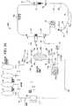
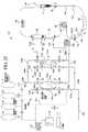
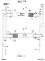
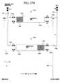
一実施形態では、2つの小型高流量透析装置は、カセットに直列に流体的に接続される。透析液および血液は、透析装置および体外回路を通って逆流して流れる。しかし、一実施形態では、透析装置を通る透析液の流れは、代わりに並流する、つまり血液回路を通る血液の流れと同方向に流れる。制限手段は、透析液流路内の2つの透析装置間に配置される。この制限手段は、好ましい一実施形態では可変および調節可能であり、異なる治療条件を考慮に入れるか、または1回の治療時に調節することができる。この制限手段は、別法によると、比較的小さいオリフィスを有するオリフィスプレートなど、単純な固定制限手段である。濾過器間の制限手段により、静脈透析装置内に正圧が形成され、高度の意図的な逆濾過が生じる。透析装置間の制限手段のサイズに応じて、このような逆濾過によって、高流量静脈−膜を通る透析液の著しい流量が直接血液内に流入する。逆濾過された溶液は、その後、動脈透析装置を通して患者から限外濾過される。透析液が静脈濾過器内の血液中に移動し、透析液が動脈透析装置から除去されると、毒素が患者から対流搬送される。さらに、患者の体内に直接移動しないが、代わりに両方の透析装置の膜を横断して流れる透析液は、老廃物の拡散浄化を形成する。 In one embodiment, the two small high flow dialysis devices are fluidly connected in series to the cassette. Dialysate and blood flow back through the dialyzer and extracorporeal circuit. However, in one embodiment, the dialysate flow through the dialyzer is instead co-current, that is, in the same direction as the blood flow through the blood circuit. The restricting means is disposed between two dialysis machines in the dialysate flow path. This limiting means is variable and adjustable in a preferred embodiment and can take into account different treatment conditions or be adjusted during a single treatment. This limiting means is, alternatively, a simple fixed limiting means, such as an orifice plate having a relatively small orifice. The limiting means between the filters creates a positive pressure in the venous dialyzer, resulting in a high degree of intentional backfiltration. Depending on the size of the restricting means between the dialyzers, such backfiltration causes a significant flow of dialysate through the high flow vein-membrane directly into the blood. The back-filtered solution is then ultrafiltered from the patient through an arterial dialysis machine. As the dialysate moves into the blood in the venous filter and the dialysate is removed from the arterial dialyzer, toxins are convectively conveyed from the patient. Furthermore, dialysate that does not move directly into the patient's body but instead flows across the membranes of both dialyzers forms a diffusional purification of waste.
したがって、このシステムは、対流浄化および拡散浄化の両方を形成する血液透析濾過システムとして作用する。一実施形態におけるシステムは、家庭用に構成されており、透析液および体外流路の少なくとも一部分は、家庭用揚水装置内に装填されている使い捨てカセット内で殺菌されて提供される。たとえば、このシステムは、一体化された使い捨て流体管理システムまたはカセット、および血液透析療法を行うために減菌され、予めパッケージ化された溶液を使用する携帯デバイスで良い。一実施形態におけるこのシステムは、コンパクトなサイズ、治療準備の容易さ、水処理および透析液配分システムの必要性がないという点で、特に家庭での使用に適している。 Thus, this system acts as a hemodiafiltration system that forms both convective purification and diffusion purification. The system in one embodiment is configured for home use, and at least a portion of the dialysate and extracorporeal flow path is provided being sterilized in a disposable cassette loaded in the home pumping device. For example, the system can be an integrated disposable fluid management system or cassette and a portable device that uses a sterile, prepackaged solution to perform hemodialysis therapy. The system in one embodiment is particularly suitable for home use in that it is compact in size, easy to prepare for treatment, and eliminates the need for water treatment and dialysate distribution systems.
現在の血液透析機械と違って、患者は、複雑な管集合を管理する必要がない。患者は、カセットを腎不全治療機械内に配置し、溶液バッグを機械に接続し、自動化プライミングシーケンスを開始するだけである。プライミングが完了したら、患者は、血液ラインを患者の身体に接続し、透析療法を開始する。治療の最後に、患者の血液は患者の体内に返される。患者は、単に、限外濾過液(「UF」)廃棄物を処分して、治療が終了し、患者は、複雑な消毒手順を行う必要はない。 Unlike current hemodialysis machines, patients do not have to manage complex tube assemblies. The patient simply places the cassette in the renal failure treatment machine, connects the solution bag to the machine, and initiates an automated priming sequence. When priming is complete, the patient connects the blood line to the patient's body and begins dialysis therapy. At the end of treatment, the patient's blood is returned to the patient. The patient simply disposes of ultrafiltrate ("UF") waste and the treatment is complete, and the patient does not have to perform a complex disinfection procedure.
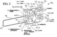
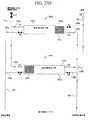
一実施形態では、カセットベースのシステムは、以下のとおりに動作する。血液ポンプは患者から血液を取り出し、血液を両方の血液透析装置に押し入れ、血液を患者に返す。透析溶液は、透析液源から取り出され、所望の患者の体温まで加熱される。輸液ポンプは、新鮮透析液をバッグから静脈透析装置内に揚送する。制限手段は、透析液流路内の2つの透析装置間に配置され、静脈透析装置を介して、透析液を血液中に逆濾過するのを促進する。制限手段は、可変であることが好ましいが、別法によると固定される。 In one embodiment, the cassette-based system operates as follows. The blood pump removes blood from the patient, pushes the blood into both hemodialysis machines, and returns the blood to the patient. The dialysate solution is removed from the dialysate source and heated to the desired patient body temperature. The infusion pump pumps fresh dialysate from the bag into the venous dialyzer. The restricting means is disposed between the two dialyzers in the dialysate flow path and facilitates reverse filtration of the dialysate into the blood via the venous dialyzer. The limiting means is preferably variable, but is fixed according to another method.
輸液ポンプから流出する流れは、制限手段において流体を押し進め、静脈血液透析装置内に正圧を生成する。高流量膜を使用すると、背圧は、透析液の一部分、たとえば50%以上を患者の血液ライン内に押し入れる。残りの透析液は、動脈透析装置を貫流する。 The flow out of the infusion pump pushes the fluid through the restricting means and creates a positive pressure in the venous hemodialysis machine. Using a high flow membrane, the back pressure forces a portion of the dialysate, eg, 50% or more, into the patient's blood line. The remaining dialysate flows through the arterial dialyzer.
排水ポンプは、輸液ポンプによって供給された当量の流体を流路から除去し、透析間の期間に患者に生じた体液喪失を補填する。次に、使用済み流体および限外濾過液は、排水バッグ内に入れるか、または外部の排水管に廃棄される。 The drainage pump removes an equivalent amount of fluid supplied by the infusion pump from the flow path to compensate for fluid loss that occurred to the patient during the period between dialysis. The spent fluid and ultrafiltrate are then placed in a drain bag or discarded into an external drain.
カセットベースの透析液は、静脈透析装置に対する透析液流と、動脈透析装置からの透析液流を平衡させて、患者の体液状態を維持するように調節される。その平衡能力によって、同じ量の流体が、静脈透析装置内で体外回路内に逆濾過される場合と同様、動脈血液透析装置内で患者から限外濾過される。この流体を血液から限外濾過すると、溶質牽引作用を生じ、この作用は、血液濾過に類似する毒素の対流搬送を提供する。ある程度の透析液は、静脈内の線維に沿って動脈透析装置に流れるため、毒素も血液から拡散搬送される。 The cassette-based dialysate is adjusted to balance the dialysate flow to the venous dialyzer and the dialysate flow from the arterial dialyzer to maintain patient fluid status. Due to its balancing capability, the same amount of fluid is ultrafiltered from the patient in the arterial hemodialysis machine, just as it is backfiltered in the extracorporeal circuit in the venous dialyzer. Ultrafiltration of this fluid from the blood produces a solute traction effect, which provides convective transport of toxins similar to hemofiltration. A certain amount of dialysate flows along the fibers in the vein to the arterial dialyzer, so that toxin is also diffused from the blood.
気泡検出器、加熱要素、圧力センサ、温度センサなども、患者を安全に治療し、システムを確実に動作させるために必要な場合、透析液の管理面および体外の血液面の両方に関してカセット内に一体化される。 Air bubble detectors, heating elements, pressure sensors, temperature sensors, etc. can also be placed in the cassette for both the dialysate management and extracorporeal blood surfaces when necessary to safely treat the patient and ensure that the system operates. Integrated.
最近公表された研究論文には、超高純度透析液は、標準の透析液と比較してより良好な結果を生成することが示されている。予めパッケージ化され、殺菌された透析液を本発明の一実施形態に使用すると、超高純度透析液に比べてさらに良好ではないにしても、同様に良好な結果を生成する。しかし、本発明は、予めパッケージ化された透析液バッグの使用に限定されるのではなく、むしろ、オンラインまたは家庭で生成される透析液を使用することができる。患者にとってのオンラインシステムの利点は、溶液バッグ、および溶液バッグが占める空間をなくすことができる点である。透析液は、殺菌バッグから供給されるか、またはオンラインで生成されるかに関わらず、1つまたは複数の炭または吸着剤カートリッジを使用する1つまたは複数のループ内で再循環させても良い。 Recently published research papers show that ultra high purity dialysate produces better results compared to standard dialysate. Using pre-packaged and sterilized dialysate in one embodiment of the present invention produces equally good results if not better than ultra high purity dialysate. However, the present invention is not limited to the use of prepackaged dialysate bags, but rather dialysate generated online or at home can be used. An advantage of an on-line system for the patient is that the solution bag and the space occupied by the solution bag can be eliminated. The dialysate may be recirculated in one or more loops using one or more charcoal or adsorbent cartridges, whether supplied from a sterilization bag or generated online. .
家庭で生成する1つの好ましいシステムについて、本明細書で説明する。このシステムは、剛性容器内に取り付けられた5リットルの減菌透析液バッグなどの貯槽を使用する。シャントは、洗浄およびプライミングの開始時に透析装置を横断して配置される。治療時、尿素交換または結合尿素を使用して動作する吸着剤カートリッジは、後透析装置または限外濾過器(「UF」)ループ内に配置される。吸着剤は、β2ミクログロブリンまたはリン酸塩など、その他の物質を除去する。一連の輸液ポンプは、同時に、透析液を減菌バッグから取り出し、加熱器、限外濾過器およびシャントを通して吸着剤カートリッジに送る。必要な場合、カルシウム、マグネシウムおよびカリウムを含むγ殺菌注入剤などの注入剤が、透析液貯槽に添加される。 One preferred system for generating at home is described herein. This system uses a reservoir such as a 5 liter sterile dialysate bag mounted in a rigid container. The shunt is placed across the dialyzer at the start of washing and priming. During treatment, adsorbent cartridges that operate using urea exchange or bound urea are placed in a post-dialyzer or ultrafilter ("UF") loop. The adsorbent removes other substances such as β2 microglobulin or phosphate. A series of infusion pumps simultaneously removes dialysate from the sterilization bag and sends it through a heater, ultrafilter and shunt to the adsorbent cartridge. If necessary, an infusate such as a gamma sterilizing infusate containing calcium, magnesium and potassium is added to the dialysate reservoir.
溶液が加熱され、治療の準備が整った後、血液治療機械は、使用者にカセットを設置するように促す。血液回路は、動脈血液ラインを介して取り付けられている生理食塩水バッグを使うか、または血液治療静脈濾過器を通して透析液を逆濾過することによりプライミングすることができる。気泡検出器、加熱要素、圧力センサ、温度センサなどは、患者を安全に治療し、システムを確実に動作させるために必要な場合、透析液および体外血液回路の両方に関してカセット内に一体化される。 After the solution is heated and ready for treatment, the blood treatment machine prompts the user to install the cassette. The blood circuit can be primed using a saline bag attached via an arterial blood line or by backfiltering dialysate through a blood treatment venous filter. Air bubble detectors, heating elements, pressure sensors, temperature sensors, etc. are integrated into the cassette for both dialysate and extracorporeal blood circuits when needed to safely treat the patient and ensure system operation .
次に、患者は動脈針および静脈針に取り付けられ、治療が開始する。治療を短くするため、透析液の流れは比較的高度、たとえば3時間で毎分300ミリリットル、または8時間以下で毎分100ミリリットルにして良い。透析液/UF流量制御ポンプは、透析装置との間の流れを制御する。流出透析液を動脈透析装置から取り出すポンプの周波数を増加することにより、透析間の期間に患者内に蓄積する流体を除去する。透析液/UF流量制御ポンプの部分は、一実施形態における血液ポンプの部分と共にカセット内に一体化されるか、または別法によると、カセットとは別個に提供され、機械の内部に一体化される。 The patient is then attached to the arterial and venous needles and treatment begins. To shorten the treatment, the dialysate flow may be relatively high, for example 300 ml / min in 3 hours, or 100 ml / min in 8 hours or less. The dialysate / UF flow control pump controls the flow to and from the dialyzer. By increasing the frequency of the pump that removes effluent dialysate from the arterial dialyzer, fluid that accumulates in the patient during the period between dialysis is removed. The dialysate / UF flow control pump portion is integrated into the cassette with the blood pump portion in one embodiment or, alternatively, is provided separately from the cassette and integrated into the interior of the machine. The
バッグを吊るして保管することは非実際的であるため、溶液バッグベースのシステムは、治療ごとの透析液の実用的な総量に限られる。吸着剤ベースの流体再生システムは、比較的多くの透析液を使用する治療を可能にし、その結果、廃棄物の浄化が強化される。透析液を増量することは、腎臓患者からの老廃物の浄化を有利に強化する。たとえば、吸着剤カートリッジは、透析液の流量が毎分200〜250ミリリットル、または治療全体で約500リットルの場合に、4時間使用することができ、これは、透析液を増量し、血液濾過システム全体により良好に廃棄物を浄化することになるであろう。吸着剤システムは、本明細書に使用する血液濾過システムに適用することもでき、予備希釈HFも可能にする。血液濾過の場合、再利用可能な追加の限外濾過器は、細菌および内毒素の除去の余剰分を維持するために提供される。 Because it is impractical to hang and store the bag, solution bag-based systems are limited to a practical total amount of dialysate per treatment. The adsorbent-based fluid regeneration system allows treatment using a relatively large amount of dialysate, resulting in enhanced waste purification. Increasing dialysate advantageously enhances the purification of waste products from kidney patients. For example, the adsorbent cartridge can be used for 4 hours when the dialysate flow rate is 200-250 milliliters per minute, or about 500 liters for the entire treatment, which increases the dialysate volume and the blood filtration system. Overall, it will clean up the waste better. The adsorbent system can also be applied to the hemofiltration system used herein and also allows for pre-dilution HF. In the case of hemofiltration, an additional reusable ultrafilter is provided to maintain a surplus of bacterial and endotoxin removal.
吸着剤ベースの再生システムは、多数の溶液バッグを保管する必要性をなくし、治療の準備を簡単にし、患者の給水栓に接続する必要性がないため、特に家庭用に適する。また、患者は、管集合を接続する必要がない。患者は、その代わりに、カセットを機械の内部に配置し、減菌透析液の最初の5リットルバッグを貯槽に追加し、自動化プライミングシーケンスを開始する。プライミングが完了したら、患者は、自身を血液回路に接続し、透析療法を開始する。 The adsorbent-based regeneration system is particularly suitable for home use because it eliminates the need to store multiple solution bags, simplifies treatment preparation, and eliminates the need to connect to a patient hydrant. In addition, the patient does not need to connect tube assemblies. Instead, the patient places the cassette inside the machine, adds the first 5 liter bag of sterile dialysate to the reservoir, and begins an automated priming sequence. When priming is complete, the patient connects himself to the blood circuit and begins dialysis therapy.
携帯デバイス、予めパッケージ化された溶液またはオンライン流体生成システムの使用、および使い捨て式セットの使用は、それぞれ、従来は腹膜透析患者のみに可能だった融通性および自由度を透析患者に提供する。専用の給水接続部がなく、本発明の機械は小型であるため、患者は、本発明のシステムを使用して移動し、路上で血液治療透析セッションを行うことが可能である。本明細書に記載するシステムおよび方法の多くは、センター内の溶液に使用するように適応させることができ、本発明の多くの態様は家庭での使用に限られない。 The use of portable devices, pre-packaged solution or on-line fluid generation systems, and the use of disposable sets each provide dialysis patients with the flexibility and freedom previously only possible for peritoneal dialysis patients. Since there is no dedicated water connection and the machine of the present invention is small, the patient can move using the system of the present invention and perform a blood therapy dialysis session on the road. Many of the systems and methods described herein can be adapted for use with in-center solutions, and many aspects of the invention are not limited to home use.
高対流血液透析は、毒素の拡散搬送のほかに対流浄化を有するため、従来の血液濾過と比較してより効果的であると考えられる。この治療法は、末期腎臓患者の小分子、中分子および大分子の廃棄物も良好に浄化すると予想される。 High convection hemodialysis is considered to be more effective than conventional hemofiltration because it has convective purification in addition to diffusive transport of toxins. This treatment is expected to clean well small, medium and large molecule waste from end-stage renal patients.
このデバイスは、必要な給水および透析配分システムを利用できない状況で、病院内で急性患者に使用するのに良く適する。本発明のデバイスは、容易に組み立てられ、断続的に急性の状況で容易に使用される。 This device is well suited for use with acute patients in hospitals in situations where the necessary water supply and dialysis distribution systems are not available. The device of the present invention is easily assembled and is easily used in intermittent acute situations.
本発明は、体外回路または透析装置に供給される透析液または補充液の量を制御するだけではなく、患者から除去される限外濾過液の量も正確に制御する複数の方法および装置を提供する。様々な代案は、主に3つのタイプに分類することができる。使用される1つのタイプの制御は、ボイルの法則に基づく空気圧制御である。この場合、流体ポンプは、既知量の空気と連通させて配置される。このシステムは、ボイルの法則を使用して、既知の値または測定した値を方程式に入れて、患者に揚送されるポンプチャンバからの流体の量を正確に計算する(たとえば、空気と対比して)。この方法および装置は、生成された流体および空気圧信号を使用して、方程式に入れる数に変換する。この方程式は、ポンプのサイクルまたは行程ごとに揚送される流体の量を与える。一実施形態におけるボイルの法則によるシステムは、最終行程またはポンプサイクル基準で正確な情報を提供するが、必ずしも実時間基準ではない。本発明は、実時間基準で流量データを生成するボイルの法則に基づくシステムおよび方法も含む。 The present invention provides multiple methods and devices that not only control the amount of dialysate or replenisher supplied to the extracorporeal circuit or dialyzer, but also accurately control the amount of ultrafiltrate removed from the patient. To do. The various alternatives can be classified into three main types. One type of control used is pneumatic control based on Boyle's law. In this case, the fluid pump is placed in communication with a known amount of air. This system uses Boyle's law to put known or measured values into the equation to accurately calculate the amount of fluid from the pump chamber that is pumped to the patient (e.g., compared to air). And). The method and apparatus uses the generated fluid and pneumatic signals to convert them into numbers that can be put into the equation. This equation gives the amount of fluid pumped per pump cycle or stroke. The Boyle Law system in one embodiment provides accurate information on a final stroke or pump cycle basis, but not necessarily a real time basis. The present invention also includes a system and method based on Boyle's law that generates flow data on a real-time basis.
容積制御の第2の大きいカテゴリは、平衡デバイスの使用を含む。こうした平衡デバイスを使用する多くの実施形態について、以下で説明する。平衡デバイスの実施形態は、主に2つの小グループに分類される。1つの小グループは、単一の平衡デバイスを使用し、もう1つの小グループは二重平衡デバイスを使用する。 The second large category of volume control involves the use of balancing devices. A number of embodiments using such balancing devices are described below. The balanced device embodiments are mainly divided into two small groups. One small group uses a single balanced device and the other small group uses a double balanced device.
本発明は、複数の異なるタイプの平衡デバイスも示唆し、開示する。一実施形態では、このシステムは1つまたは2つの平衡チャンバを使用する。別の実施形態では、このシステムは、1つまたは2つの平衡管を使用する。平衡管は環状筐体を備え、筐体内にピストンまたはボール状の隔離板を有する。隔離板は、平衡チャンバの膜または隔膜と同様に動作する。 The present invention also suggests and discloses several different types of balancing devices. In one embodiment, the system uses one or two equilibrium chambers. In another embodiment, the system uses one or two balance tubes. The balance tube has an annular housing and has a piston or ball-shaped separator in the housing. The separator operates in the same manner as the membrane or diaphragm of the equilibrium chamber.
第3のタイプの平衡デバイスは、1つまたは複数の蛇行経路である。蛇行経路は、一実施形態では、使い捨てカセットによって長形チャネルとして画定される。チャネルの直径または断面積は、新鮮または流出透析液のバルク移動が、蛇行経路内の流体の既存バルクを効率的に移動させることができるように構成される。つまり、バルクの新鮮透析液は、排水管に至る経路内に現在存在する消費または流出透析液のバルクを移動させる。次のサイクルでは、バルクの消費または流出透析液は、導入されたバルクの新鮮な流体を患者または透析装置に至る蛇行経路内に押し入れる。この経路の断面および長さは、流体のバルクの終わりにおける新鮮および消費流体の混合量を最小化するように構成される。 A third type of balancing device is one or more serpentine paths. The serpentine path is, in one embodiment, defined as a long channel by a disposable cassette. The channel diameter or cross-sectional area is configured such that bulk movement of fresh or effluent dialysate can efficiently move the existing bulk of fluid in the tortuous path. That is, the bulk fresh dialysate moves the bulk of the currently consumed or spilled dialysate present in the path to the drain. In the next cycle, the bulk consumption or effluent dialysate pushes the introduced bulk fresh fluid into the tortuous path to the patient or dialyzer. The cross-section and length of this path is configured to minimize the amount of fresh and consumed fluid mix at the end of the fluid bulk.
様々な容積平衡デバイスは、多くの異なるタイプのポンプ、たとえば蠕動ポンプ、膜ポンプ、ギヤポンプ、またはこれらの組合せと共に使用することができる。単一ポンプは、平衡デバイスと共に使用される。別個の新鮮透析液ポンプおよび使用済み透析液ポンプは、交互に使用される。さらに、別個の限外濾過液ポンプも意図および説明されており、このポンプは、主ポンプを患者との間の当容積の流体の揚送専用にすることを可能にする。 The various volume balance devices can be used with many different types of pumps, such as peristaltic pumps, membrane pumps, gear pumps, or combinations thereof. A single pump is used with a balancing device. Separate fresh dialysate pumps and spent dialysate pumps are used alternately. In addition, a separate ultrafiltrate pump is also contemplated and described, which allows the main pump to be dedicated to pumping a volume of fluid to and from the patient.
第3の主なタイプの流体管理は、重量または重量計を使用して、患者に供給される流体の量、および患者から除去される流体の量を測定する。以下で説明する一実施形態では、流体バッグは、シャフトに結合されたスタンド上に配置される。一方の端部では、シャフトは転動形ダイアフラムに結合する。転動形ダイアフラムは、その他の装置と関連して、閉鎖しているが可変の容積を画定する。流体バッグの重量は変動するため、容積内の圧力も変動する。圧力センサは圧力を感知し、機械の制御装置またはプロセッサは、圧力センサからの信号を処理して、対応する重量信号を展開する。次に、重量信号を使用して、動脈瘤嚢程度の流体が供給されたか、および/または患者から除去されたかが決定される。一実施形態では、新鮮流体バッグおよび使用済み流体バッグは、同じ重量感知デバイスによって測定されるため、システムは、患者から除去された限外濾過液により、長期にわたる正味の全体重量増加を観察することを予測する。この用途には、ロードセルを使用することもできる。 The third main type of fluid management uses weights or scales to measure the amount of fluid delivered to the patient and the amount of fluid removed from the patient. In one embodiment described below, the fluid bag is placed on a stand coupled to the shaft. At one end, the shaft is coupled to a rolling diaphragm. The rolling diaphragm, in conjunction with other devices, defines a closed but variable volume. Since the weight of the fluid bag varies, the pressure within the volume also varies. The pressure sensor senses the pressure, and the machine controller or processor processes the signal from the pressure sensor to develop a corresponding weight signal. The weight signal is then used to determine whether an aneurysmal sac-like fluid has been delivered and / or removed from the patient. In one embodiment, the fresh fluid bag and the used fluid bag are measured by the same weight sensing device, so the system observes a net overall weight increase over time due to the ultrafiltrate removed from the patient. Predict. A load cell can also be used for this purpose.
以下に詳細に説明するとおり、本発明は、システムのその他の構成要素に関する複数の実施形態および本発明の方法、たとえば流体加熱器、平衡デバイス、使い捨てカセット、バッグ位置決め、および本発明のその他の重要な特徴を提供する。たとえば、本発明は接近切断センサ(「ADS」)を含み、これは、動脈または静脈の針が、治療時に患者から偶発的に取り外された場合に検出することができる。さらに、様々な圧力除去計画、完全性テストなどについて本明細書で説明するが、これは、患者が就寝中に使用する家庭用機械の場合に特に重要である。 As described in detail below, the present invention provides a plurality of embodiments and other methods of the present invention relating to other components of the system, such as fluid heaters, balancing devices, disposable cassettes, bag positioning, and other important features of the present invention. Provide unique features. For example, the present invention includes an access cutting sensor (“ADS”), which can detect when an arterial or venous needle is accidentally removed from a patient during treatment. In addition, various pressure relief schemes, integrity tests, etc. are described herein, which is particularly important in the case of home machines that patients use while sleeping.
したがって、本発明の利点は、家庭または臨床環境で使用可能な血液透析、血液濾過または血液透析濾過システムを提供することである。 Accordingly, an advantage of the present invention is to provide a hemodialysis, hemofiltration or hemodiafiltration system that can be used in a home or clinical environment.
本発明のもう1つの利点は、家庭にいる患者が、減菌血液治療システムを容易に組み立てることを可能にするカセットベースの血液濾過/血液透析濾過システムを提供することである。 Another advantage of the present invention is to provide a cassette-based hemofiltration / dialysis filtration system that allows patients at home to easily assemble a sterile blood treatment system.
本発明のもう1つの利点は、腎不全血液治療法の効果を改善することである。 Another advantage of the present invention is to improve the effectiveness of renal failure blood therapy.
さらに、本発明の利点は、対流および拡散モードの浄化を使用する腎不全血液療法を提供することである。 Furthermore, an advantage of the present invention is to provide renal failure blood therapy using convective and diffusion mode clearance.
さらに、本発明の利点は、拡散および対流浄化モードの両方が提供され、何れのモードの割合も変更することができる腎不全血液療法を提供することである。 Furthermore, an advantage of the present invention is to provide renal failure blood therapy in which both diffusion and convective purification modes are provided and the rate of either mode can be changed.
さらに、本発明の利点は、血液透析、強化対流血液透析、血液濾過または血液透析濾過法を行うために、現場で構成可能なカセットベースの血液療法を提供することである。 Furthermore, an advantage of the present invention is to provide a cassette-based blood therapy that can be configured in the field to perform hemodialysis, enhanced convection hemodialysis, hemofiltration or hemodiafiltration.
さらに、本発明の利点は、新鮮透析液の消費量を最適化する1つまたは複数の治療流体循環ループを有する血液治療システムを提供することである。 Furthermore, an advantage of the present invention is to provide a blood treatment system having one or more treatment fluid circulation loops that optimize fresh dialysate consumption.
本発明のさらにもう1つの利点は、複数の異なるタイプの治療流体、たとえば溶液バッグ、溶液調合ユニットまたはオンライン透析液生成システムで動作するように構成された家庭用腎不全血液治療法を提供することである。 Yet another advantage of the present invention is to provide a home renal failure blood therapy configured to operate with a plurality of different types of treatment fluids, such as solution bags, solution preparation units or online dialysate generation systems. It is.
本発明のさらに他の利点は、流体交換量、および患者から除去される流体量または限外濾過液量を正確に制御する多くのタイプのシステムで動作可能な家庭用腎不全治療システムを提供することである。 Yet another advantage of the present invention is to provide a home renal failure treatment system operable with many types of systems that accurately control the amount of fluid exchange and the amount of fluid or ultrafiltrate removed from the patient. That is.
さらに、本発明の利点は、流量制御デバイスを改善することである。 Furthermore, an advantage of the present invention is to improve the flow control device.
本発明は、さらに以下を提供する。
(項目1)
医用流体治療システムであって、
患者に結合されるように構成され、配列される血液ラインと、
該血液ラインに接続されるポンプと、
該血液ラインと連通し、該患者からの血液を収容するように配置される第1透析装置部分と、
該第1透析装置部分からの血液を収容するように配置される第2透析装置部分と、
治療流体源に接続され、第1および第2透析装置部分と流体連通する治療流体ラインと、
該第1透析装置部分と第2透析装置部分間で該治療流体ラインに連通する流量制限手段であって、該制限手段が、該第1透析装置部分および第2透析装置部分の一方で、治療流体の背圧を選択的に増加/減少させるように可変である制限手段と
を備える、医用流体治療システム。
(項目2)
前記第1部分、第2部分および制限手段が1つの筐体内に設けられる、項目1に記載の医用流体治療システム。
(項目3)
前記第1部分および第2部分が別個に収容される、項目1に記載の医用流体治療システム。
(項目4)
流量制限手段に結合されたデバイスを備え、該デバイスが、前記流量制限手段の流量抵抗を変更するように操作可能である、項目1に記載の医用流体治療システム。
(項目5)
前記デバイスが手動または自動で作動される、項目4に記載の医用流体治療システム。
(項目6)
血液ラインおよび治療流体ラインの少なくとも一方の少なくとも一部分が使い捨て式である、項目1に記載の医用流体治療システム。
(項目7)
第1部分、第2部分および流量制限手段の少なくとも1つが使い捨て式である、項目1に記載の医用流体治療システム。
(項目8)
第1部分、第2部分、流量制限手段、血液ライン部分、および治療流体ライン部分の少なくとも1つを含む使い捨てカセットをさらに備える、項目1に記載の医用流体治療システム。
(項目9)
ポンプが第1ポンプであり、治療流体を揚送するように構成および配列された少なくとも1つの追加のポンプを備える、項目1に記載の医用流体治療システム。
(項目10)
追加のポンプが、膜ポンプ、蠕動ポンプ、ピストンポンプ、空気圧作動ポンプ、ピストンポンプ、空気圧付勢ポンプ、およびこれらの任意の組合せからなる群から選択されるタイプである、項目9に記載の医用流体治療システム。
(項目11)
対向サイクル行程で動作して、治療流体を透析装置部分に供給する1対の追加のポンプを備える、項目9に記載の医用流体治療システム。
(項目12)
透析装置部分の1つに治療流体を供給するように操作可能な少なくとも1つの追加のポンプと、他方の透析装置部分から限外濾過液を除去するように操作可能な少なくとも1つの他の追加のポンプとを備える、項目9に記載の医用流体治療システム。
(項目13)
キャパシタンス流量センサと、理想気体の法則に基づいて作動する流量センサと、蠕動ポンプが行う回転/行程の数を計算するセンサと、重量計と、単一平衡チャンバと、単一平衡管と、単一蛇行経路と、二重平衡チャンバと、二重平衡管と、二重蛇行経路とからなる群から選択されたタイプの少なくとも1つの流量管理装置を備える、項目1に記載の医用流体治療システム。
(項目14)
流体が、第1および第2透析装置部分の一方に達する前に、治療流体を加熱する治療流体ラインと連通する流体加熱器を備える、項目1に記載の医用流体治療システム。
(項目15)
加熱器が、誘導、電気抵抗、対流および放射からなる群から選択される少なくとも1つのタイプである、項目14に記載の医用流体治療システム。
(項目16)
治療流体源が、少なくとも1つの携帯流体容器、治療流体調製モジュール、オンライン治療流体源、およびこれらの任意の組合せを含む、項目1に記載の医用流体治療システム。(項目17)
制限手段が、10〜90%の流体を1つの透析装置を通して血液ラインに逆流させるサイズである、項目1に記載の医用流体治療システム。
(項目18)
少なくとも1つの空気感知および/または除去デバイスを血液ラインに含む、項目1に記載の医用流体治療システム。
(項目19)
血液透析、血液濾過、血液透析濾過法、およびこれらの任意の組合せからなる群から選択される治療を行う、項目1に記載の医用流体治療システム。
(項目20)
血液濾過治療が、前希釈治療、後希釈治療、または前および後希釈治療である、項目19に記載の医用流体治療システム。
(項目21)
治療流体ラインと連通する再循環ループを備え、透析装置の1つから除去される流体が、治療流体ライン内に再導入され、第1および第2透析装置の一方と再び流体的に連通する、項目1に記載の医用流体治療システム。
(項目22)
前記再循環ラインが流体を透析装置に再導入し、該透析装置から流体が除去される、項目21に記載の医用流体治療システム。
(項目23)
流体が、再循環ループの場合、制限手段から下流に位置する透析装置から除去される、項目21に記載の医用流体治療システム。
(項目24)
再循環ループ内に位置する少なくとも1つの浄化デバイスを備え、該デバイスが、治療流体ライン内に再導入される流体を少なくとも部分的に再生するように動作する、項目21に記載の医用流体治療システム。
(項目25)
洗浄デバイスが、活性炭濾過器、吸着剤交換、化学洗浄剤、化学交換、生物学的洗剤、結合吸着剤、酵素(enzomatic)反応剤、機械的洗浄剤、およびこれらの何らかの組合せをからなる群から選択される、項目24に記載の医用流体治療システム。
(項目26)
第1および第2部分を通る治療流体の流れが、血液の流れに逆流する、項目1に記載の医用流体治療システム。
(項目27)
第1および第2部分を通る治療流体の流れが、血液の流れに並流する、項目1に記載の医用流体治療システム。
(項目28)
前記可変制限手段がモータ制御クランプを備える、項目1に記載の医用流体治療システム。
(項目29)
医用流体治療システムであって、
患者に結合されるように構成され、配列される血液ラインと、
該血液ラインに接続されるポンプと、
該血液ラインと連通し、患者からの血液を収容するように配置される第1透析装置部分と、
該第1透析装置部分とは別個に収容される第2透析装置であって、該第1透析装置から血液を収容するように配置され、配列された第2透析装置部分と、
該第1透析装置と第2透析装置との間で治療流体ラインと連通する流量制限手段であって、該制限手段が、該第1および第2透析装置の一方の治療流体の背圧を増加させるように操作可能である流量制限手段、
を備える、医用流体治療システム。
(項目30)
前記制限手段が、背圧を選択的に増加/減少させるように可変である、項目29に記載のシステム。
(項目31)
腎不全治療機械用の使い捨てユニットであって、
該機械内に配置されるように構成され、配列される筐体と、
該筐体に取り付けられる可撓性膜であって、該膜および筐体が、前記機械と協働して、腎不全治療流体の流量を制御するバルブ機能を果たす可撓性膜と、
該筐体によって支持され、患者の血液ラインの少なくとも一部分に操作可能に接続される第1および第2透析装置部分と、
該第1透析装置と第2透析装置との間に配置される流量制限手段であって、透析装置の1つの背圧を増加させるように操作可能な流量制限手段と、
を備える、使い捨てユニット。
(項目32)
前記透析装置部分が別個に収容される、項目31に記載の使い捨てユニット。
(項目33)
血液ラインが、前記機械内に収容された蠕動ポンプと操作可能に結合するように構成されたある長さの管類を備える、項目31に記載の使い捨てユニット。
(項目34)
キャパシタンス流量センサと、理想気体の法則に基づいて作動する流量センサと、蠕動ポンプが行う回転/行程の数を計算するセンサと、重量計と、単一平衡チャンバと、単一平衡管と、単一蛇行経路と、二重平衡チャンバと、二重平衡管と、二重蛇行経路とからなる群から選択されるタイプの少なくとも1つの流量管理装置を備える、項目31に記載の使い捨てユニット。
(項目35)
医用流体治療方法であって、
(a)治療流体を第1および第2透析装置部分に流す工程と、
(b)前記第1部分と第2部分間に可変流量制限手段を配置する工程と、
(c)該流体の望ましい第1部分が、前記透析装置の1つを通って血液ライン内に流入し、該流体の第2部分が、前記第2透析装置内に配置される複数の膜を実質的に横断して流れるように、可変流量制限手段を設定する工程と
を包含する、方法。
(項目36)
前記制限手段の設定によって、該流体の第3部分が、第1透析装置部分内に位置する膜を横断して流れる、項目35に記載の医用流体治療方法。
(項目37)
家庭用医用流体治療機械方法であって、
(a)人が家庭で、使い捨てカセットを機械内に装填することを可能にする工程と、
(b)治療流体を使い捨てカセットに流す工程と、
(c)導電性浄化を行うために、少なくとも25%の流体を向ける工程と、
(d)残りの流体の少なくとも実質的な量が、拡散浄化を行うことを可能にする工程とを含む家庭用医用流体治療機械方法。
(項目38)
導電性浄化を行うための流体の割合を向ける工程が、患者の血液の流れに至る透析装置の膜を通して当該割合の流体に背圧を与えることを含む、項目37に記載の家庭用医用流体治療方法。
(項目39)
限外濾過を行う方法であって、
第1および第2平衡デバイスを提供する工程と、
使用済み治療流体を該第1平衡デバイス内に揚送する工程と、
使用済み治療流体を該第1平衡デバイス内に揚送し、該第2平衡デバイスに流すことによって、治療流体を該第1平衡デバイスから排出することを可能にする工程と、
該排出された治療流体が該第2平衡デバイスに入り、該第2平衡デバイス内に保持されている使用済み治療流体を排水管に排出する工程と
を含む、方法。
(項目40)
前記使用済みおよび排出される治療流体が、透析液および補充液からなる群から選択される、項目39に記載の方法。
(項目41)
前記平衡デバイスが、平衡チャンバ、平衡管および蛇行経路からなる群から選択される、項目39に記載の方法。
(項目42)
前記第1平衡デバイスから排出される前記治療流体が新鮮な治療流体である、項目39に記載の方法。
(項目43)
入口バルブおよび出口バルブとインラインになるように配置される流体ポンプのバルブ完全性テストであって、
(a)出口バルブを閉鎖し、入口バルブを開放した状態で、流体をポンプ内に揚送する工程と、
(b)入口バルブを閉鎖し、出口バルブを閉鎖状態に維持する工程と、
(c)バルブを閉鎖した状態で、流体をポンプから揚送しようと試みる工程と、
(d)ポンプ内の流体の容量の変化が検出された場合、バルブの少なくとも1つに漏れがあると決定する工程と
を含む、バルブ完全性テスト。
(項目44)
キャパシタンス流量センサを使用して、ポンプ内の容量の変化が生じたか否かを検出する、項目43に記載の完全性テスト。
(項目45)
工程(a)〜(d)を医用流体治療全体で周期的に行うことを含む、項目43に記載の完全性テスト。
(項目46)
血液透析、血液濾過、血液透析濾過法、腹膜透析、およびこれらの任意の組合せからなる群から選択される治療のために、工程(a)〜(c)を行うことを含む、項目43に記載の完全性テスト。
(項目47)
実時間基準で容量を感知する方法であって、
膜ポンプチャンバ内の空気の量と、該ポンプチャンバと連通する一定容積の容器内の空気の量とを含む初期空気総量を取得する工程と、
ポンプチャンバ内の膜を移動させて、流体をポンプチャンバから排出するか、または流体をポンプチャンバ内に引き込む工程と、
初期圧力、および総量が変化した後の時間Tにおける圧力を測定する工程と、
該初期総量、初期圧力および時間Tにおける圧力を使用して、時間Tの総空気量を計算する工程と、
初期空気総量、および時間Tの総空気量を使用して、揚送される量を決定する工程とを含む方法。
(項目48)
一定容積の容器が圧力チャンバである、項目47に記載の方法。
(項目49)
医用流体治療システムであって、
患者に結合するように構成され、配列される血液ラインと、
血液ラインに接続される血液ポンプと、
該血液ラインと連通する血液濾過器であって、患者の血液の液体部分が濾過器を通過して治療流体流路に入ることを可能にするように操作可能な濾過器と、
治療流体を血液ラインに、また治療流体を血液ラインから交互に、実質的に連続して揚送するように配置され、配列される1対の蠕動流体ポンプと、
血液ラインに揚送されるある量の治療流体と、濾過器から揚送されるある量の流体とを制御するように操作可能な少なくとも1つの容量制御デバイスとを含む医用流体治療システム。
(項目50)
蠕動ポンプが、治療流体の交互の、実質的に連続する揚送を行うことができるように操作可能な複数のバルブを備える、項目49に記載の医用流体治療システム。
(項目51)
濾過器の上流または下流にある血液ラインに治療流体を選択的に揚送するように操作可能である、項目49に記載の医用流体治療システム。
(項目52)
治療流体を濾過器に揚送して、対流および/または拡散血液浄化を行うように構成される、項目49に記載の医用流体治療システム。
(項目53)
前記容量制御デバイスが、キャパシタンス流量センサと、理想気体の法則に基づいて動作する流量センサと、蠕動ポンプによって行われる回転/行程の数を計算するセンサと、重量計と、単一平衡チャンバと、単一平衡管と、単一蛇行経路と、二重平衡チャンバと、二重平衡管と、二重蛇行経路とからなる群から選択されるタイプである、項目49に記載の医用流体治療システム。
(項目54)
医用流体治療システムであって、
患者に結合するように構成され、配列される血液ラインと、
該血液ラインに接続される血液ポンプと、
該血液ラインと連通し、患者の血液の液体部分が濾過器を通過して治療流体流路に入ることを可能にするように操作可能な血液濾過器と、
治療流体を血液ラインに揚送するように操作可能な第1ポンプと、
流体を濾過器から揚送するように操作可能な第2ポンプと、
濾過器から揚送される少なくともある程度の流体を、流体再生デバイスを通して血液ライン内に送るように操作可能な再循環経路と
を備える、医用流体治療システム。
(項目55)
前記再生デバイスが活性炭、吸着剤、これらの任意の組合せを含む、項目54に記載の医用流体治療システム。
(項目56)
濾過器の上流または下流にある血液ラインに治療流体を選択的に揚送するように操作可能である、項目54に記載の医用流体治療システム。
(項目57)
治療流体を濾過器にさらに揚送して、拡散血液浄化を行うように構成される、項目54に記載の医用流体治療システム。The present invention further provides the following.
(Item 1)
A medical fluid therapy system comprising:
A blood line configured and arranged to be coupled to a patient;
A pump connected to the blood line;
A first dialyzer portion in communication with the blood line and arranged to receive blood from the patient;
A second dialyzer part arranged to receive blood from the first dialyzer part;
A treatment fluid line connected to the treatment fluid source and in fluid communication with the first and second dialyzer parts;
A flow restricting means communicating with the treatment fluid line between the first dialyzer part and the second dialyzer part, wherein the restricting means is one of the first dialyzer part and the second dialyzer part. A medical fluid therapy system comprising limiting means that is variable to selectively increase / decrease the fluid back pressure.
(Item 2)
(Item 3)
The medical fluid treatment system according to
(Item 4)
The medical fluid therapy system of
(Item 5)
(Item 6)
The medical fluid treatment system of
(Item 7)
(Item 8)
The medical fluid treatment system of
(Item 9)
2. The medical fluid treatment system of
(Item 10)
(Item 11)
(Item 12)
At least one additional pump operable to supply therapeutic fluid to one of the dialyzer parts and at least one other additional operable to remove ultrafiltrate from the
(Item 13)
Capacitance flow sensors, flow sensors that operate according to the ideal gas law, sensors that calculate the number of rotations / strokes that the peristaltic pump performs, a weigh scale, a single equilibrium chamber, a single equilibrium tube, and a single 2. The medical fluid therapy system of
(Item 14)
2. The medical fluid treatment system of
(Item 15)
(Item 16)
The medical fluid treatment system of
(Item 18)
2. The medical fluid therapy system of
(Item 19)
(Item 20)
20. The medical fluid therapy system of item 19, wherein the hemofiltration therapy is a pre-dilution therapy, a post-dilution therapy, or a pre- and post-dilution therapy.
(Item 21)
A recirculation loop in communication with the treatment fluid line, wherein fluid removed from one of the dialysis devices is reintroduced into the treatment fluid line and is again in fluid communication with one of the first and second dialysis devices;
(Item 22)
(Item 23)
(Item 24)
22. The medical fluid treatment system of item 21, comprising at least one purification device located in the recirculation loop, the device operating to at least partially regenerate fluid reintroduced into the treatment fluid line. .
(Item 25)
The cleaning device is from the group consisting of an activated carbon filter, an adsorbent exchange, a chemical detergent, a chemical exchange, a biological detergent, a bound adsorbent, an enzymatic reagent, a mechanical detergent, and some combination thereof 25. The medical fluid therapy system according to
(Item 26)
(Item 27)
The medical fluid treatment system of
(Item 28)
(Item 29)
A medical fluid therapy system comprising:
A blood line configured and arranged to be coupled to a patient;
A pump connected to the blood line;
A first dialyzer portion in communication with the blood line and positioned to receive blood from a patient;
A second dialyzer housed separately from the first dialyzer part, the second dialyzer part arranged and arranged to contain blood from the first dialyzer;
A flow restricting means in communication with a treatment fluid line between the first dialyzer and the second dialyzer, the restricting means increasing the back pressure of one of the treatment fluids of the first and second dialyzer. Flow restricting means, operable to
A medical fluid therapy system comprising:
(Item 30)
30. A system according to item 29, wherein the limiting means is variable to selectively increase / decrease back pressure.
(Item 31)
A disposable unit for a renal failure treatment machine,
A housing configured and arranged to be disposed within the machine;
A flexible membrane attached to the housing, wherein the membrane and the housing cooperate with the machine to perform a valve function to control the flow rate of renal failure treatment fluid;
First and second dialyzer portions supported by the housing and operably connected to at least a portion of a patient's blood line;
A flow restricting means disposed between the first dialyzer and the second dialyzer, the flow restricting means operable to increase one back pressure of the dialyzer;
A disposable unit comprising:
(Item 32)
32. A disposable unit according to item 31, wherein the dialyzer parts are accommodated separately.
(Item 33)
32. The disposable unit of item 31, wherein the blood line comprises a length of tubing configured to operably couple with a peristaltic pump contained within the machine.
(Item 34)
Capacitance flow sensors, flow sensors that operate according to the ideal gas law, sensors that calculate the number of rotations / strokes that the peristaltic pump performs, a weigh scale, a single equilibrium chamber, a single equilibrium tube, and a single 32. A disposable unit according to item 31, comprising at least one flow management device of the type selected from the group consisting of a single meander path, a double balance chamber, a double balance tube and a double meander path.
(Item 35)
A medical fluid treatment method comprising:
(A) flowing therapeutic fluid through the first and second dialyzer parts;
(B) disposing a variable flow restriction means between the first part and the second part;
(C) a desired first portion of the fluid flows through one of the dialysis devices into a blood line, and a second portion of the fluid passes through a plurality of membranes disposed in the second dialysis device. Setting the variable flow restricting means to flow substantially transversely.
(Item 36)
36. The medical fluid treatment method according to item 35, wherein the setting of the restriction means causes the third portion of the fluid to flow across a membrane located in the first dialyzer portion.
(Item 37)
A home medical fluid therapy machine method comprising:
(A) allowing a person to load a disposable cassette into the machine at home;
(B) flowing a treatment fluid through the disposable cassette;
(C) directing at least 25% of the fluid to conduct the conductive purification;
(D) a home medical fluid therapy machine method comprising the steps of allowing at least a substantial amount of the remaining fluid to perform diffusion purification.
(Item 38)
38. A home medical fluid therapy according to item 37, wherein directing the proportion of fluid to perform the conductive purification comprises applying back pressure to the proportion of fluid through the membrane of the dialyzer leading to the blood flow of the patient. Method.
(Item 39)
A method of performing ultrafiltration,
Providing first and second balancing devices;
Pumping spent treatment fluid into the first balancing device;
Allowing the treatment fluid to drain from the first balancing device by pumping spent therapy fluid into the first balancing device and flowing through the second balancing device;
The drained treatment fluid enters the second balancing device and drains spent therapy fluid retained in the second balancing device to a drain.
(Item 40)
40. The method of item 39, wherein the spent and drained treatment fluid is selected from the group consisting of dialysate and replenisher.
(Item 41)
40. The method of item 39, wherein the balancing device is selected from the group consisting of a balancing chamber, a balancing tube and a serpentine path.
(Item 42)
40. The method of item 39, wherein the treatment fluid drained from the first balancing device is fresh treatment fluid.
(Item 43)
A valve integrity test of a fluid pump arranged to be in-line with the inlet and outlet valves,
(A) a step of pumping fluid into the pump with the outlet valve closed and the inlet valve open;
(B) closing the inlet valve and maintaining the outlet valve closed;
(C) attempting to pump fluid from the pump with the valve closed;
(D) a valve integrity test comprising determining that at least one of the valves is leaking if a change in the volume of fluid in the pump is detected.
(Item 44)
44. The integrity test of item 43, wherein a capacitance flow sensor is used to detect whether a change in capacity has occurred in the pump.
(Item 45)
44. The integrity test of item 43, comprising performing steps (a)-(d) periodically throughout the medical fluid therapy.
(Item 46)
44. Item 43, comprising performing steps (a)-(c) for treatment selected from the group consisting of hemodialysis, hemofiltration, hemodiafiltration, peritoneal dialysis, and any combination thereof. Integrity test.
(Item 47)
A method for sensing capacity on a real-time basis,
Obtaining an initial total air amount including an amount of air in the membrane pump chamber and an amount of air in a fixed volume container in communication with the pump chamber;
Moving the membrane in the pump chamber to drain fluid from the pump chamber or drawing fluid into the pump chamber;
Measuring the initial pressure and the pressure at time T after the total amount has changed;
Using the initial total amount, initial pressure and pressure at time T to calculate a total air amount at time T;
Using the initial total air amount and the total air amount at time T to determine the amount to be pumped.
(Item 48)
48. The method of item 47, wherein the constant volume container is a pressure chamber.
(Item 49)
A medical fluid therapy system comprising:
A blood line configured and arranged to couple to a patient;
A blood pump connected to the blood line;
A blood filter in communication with the blood line, the filter operable to allow a liquid portion of the patient's blood to pass through the filter and into the treatment fluid flow path;
A pair of peristaltic fluid pumps arranged and arranged to pump treatment fluid to and from the blood line alternately and substantially continuously from the blood line;
A medical fluid therapy system including an amount of treatment fluid pumped to a blood line and at least one volume control device operable to control an amount of fluid pumped from a filter.
(Item 50)
50. The medical fluid treatment system of item 49, wherein the peristaltic pump comprises a plurality of valves operable to allow alternating, substantially continuous pumping of the treatment fluid.
(Item 51)
50. The medical fluid treatment system of item 49, operable to selectively pump treatment fluid to a blood line upstream or downstream of the filter.
(Item 52)
50. The medical fluid treatment system of item 49, configured to pump the treatment fluid to a filter for convection and / or diffusion blood purification.
(Item 53)
The capacitance control device includes a capacitance flow sensor, a flow sensor operating according to the ideal gas law, a sensor for calculating the number of rotations / strokes performed by the peristaltic pump, a weigh scale, a single equilibrium chamber, 50. The medical fluid therapy system of item 49, wherein the medical fluid treatment system is of a type selected from the group consisting of a single balance tube, a single meander path, a double balance chamber, a double balance pipe, and a double meander path.
(Item 54)
A medical fluid therapy system comprising:
A blood line configured and arranged to couple to a patient;
A blood pump connected to the blood line;
A hemofilter in communication with the blood line and operable to allow a liquid portion of the patient's blood to pass through the filter and into the treatment fluid flow path;
A first pump operable to pump treatment fluid to the blood line;
A second pump operable to pump fluid from the filter;
A medical fluid therapy system comprising a recirculation path operable to deliver at least some fluid pumped from the filter through the fluid regeneration device and into the blood line.
(Item 55)
55. The medical fluid treatment system of
(Item 56)
55. The medical fluid treatment system of
(Item 57)
55. The medical fluid treatment system of
本発明のさらに他の特徴および利点は、以下の本発明の詳細な説明および図面に記載されており、これらの説明および図面から明らかになるであろう。 Additional features and advantages of the present invention are described in, and will be apparent from, the following Detailed Description of the Invention and the figures.
発明の詳細な説明
概要
本発明は、治療時に逆濾過の量を増加および強化する家庭血液透析(「HHD」)療法のための様々な装置および方法を提供する。このシステムは、家庭用に設計されているにも関わらず、病院の急性腎臓治療センター、またはセルフケアセンターでの使用にも適する。このシステムは、使い捨てカセットまたは管組織オーガナイザ(本明細書では、カセットと総称する)を有する使い捨てセットを含む使い捨て流体管理システムを使用する。カセットは、透析液および体外流路の少なくとも一方の少なくとも一部分を収容する。一実施形態では、2つの小型高流量透析装置が、流体的かつ直列にカセットに接続される。一実施形態では、透析液および血液は、透析装置を通って互いに逆流する。制限手段は、透析液流路内の2つの透析装置間に配置される。制限手段は、一実施形態では、異なる治療条件を考慮するか、または1回の治療時に調節できるように可変および調節可能である。制限手段は、別法によると、制限オリフィスを有するオリフィスプレートのように固定される。DETAILED DESCRIPTION OF THE INVENTION Overview The present invention provides various devices and methods for home hemodialysis (“HHD”) therapy that increases and enhances the amount of backfiltration during treatment. The system is also suitable for use in hospital acute kidney treatment centers or self-care centers despite being designed for home use. The system uses a disposable fluid management system that includes a disposable set having a disposable cassette or a tube tissue organizer (collectively referred to herein as a cassette). The cassette contains at least a portion of at least one of the dialysate and the extracorporeal flow path. In one embodiment, two small high flow dialysis devices are connected to the cassette fluidly and in series. In one embodiment, dialysate and blood flow back through the dialyzer. The restricting means is disposed between two dialysis machines in the dialysate flow path. The limiting means is variable and adjustable in one embodiment so that it can be adjusted to account for different treatment conditions or during a single treatment. The restricting means, according to another method, is fixed like an orifice plate having a restricting orifice.
濾過器間の制限手段によって、静脈透析装置内に正圧が形成され(第1透析装置は透析液を収容し、第2透析装置は、逆流構成で血液を収容する)、意図的に比較的高度の逆濾過を生じる。透析装置間の制限手段のサイズに応じて、この逆濾過によって、透析液の著しい流量(たとえば、総透析液流量の10〜70%)が、高流量静脈膜を通って血液回路に入る。逆濾過された溶液は対流浄化を提供する。一実施形態では、限外濾過液は、動脈透析装置を介して患者から除去される(第1透析装置は血液を収容するが、第2透析装置は、逆流構成で透析液を収容する)。 By means of restriction between the filters, a positive pressure is created in the venous dialyzer (the first dialyzer contains dialysate and the second dialyzer contains blood in a reverse flow configuration) and is intentionally relatively A high degree of reverse filtration results. Depending on the size of the restricting means between the dialyzers, this backfiltration causes a significant flow of dialysate (eg, 10-70% of the total dialysate flow) to enter the blood circuit through the high flow venous membrane. The back-filtered solution provides convective purification. In one embodiment, ultrafiltrate is removed from the patient via an arterial dialysis device (the first dialysis device contains blood while the second dialysis device contains dialysate in a reverse flow configuration).
透析液が静脈透析装置内に拡散し、透析液を動脈透析装置から除去すると、毒素が患者から対流搬送される。さらに、直接体外回路内に移動しない透析液(たとえば、他の割合の透析液)は、代わりに両方の透析装置の膜を横断して流れ、老廃物の拡散浄化が行われる。このシステムは、本明細書では、強化対流血液透析(「ECHD」)システムと呼ぶ。血液透析濾過システムと同様、このシステムは、対流および拡散浄化の両方を行う。このシステムは、一実施形態では、家庭用に構成され、透析液および体外流路の少なくとも一部分が殺菌され、複数のポンプ、加熱器、バルブ作動装置などを有する機械に装填される使い捨てセットとして提供される。 As the dialysate diffuses into the venous dialyzer and the dialysate is removed from the arterial dialyzer, toxins are convectively conveyed from the patient. In addition, dialysate that does not move directly into the extracorporeal circuit (eg, other proportions of dialysate) instead flows across the membranes of both dialysers to effect diffusion of waste. This system is referred to herein as an enhanced convection hemodialysis (“ECHD”) system. Like the hemodiafiltration system, this system performs both convection and diffusion purification. The system, in one embodiment, is configured for home use and is provided as a disposable set that is loaded into a machine having multiple pumps, heaters, valve actuators, etc., with at least a portion of the dialysate and extracorporeal channels sterilized. Is done.
強化対流血液透析(「ECHD」)
次に、図面、特に図1を参照すると、腎不全治療システム10の一実施形態が示されている。システム10は、2つ以上の高流量血液透析装置、たとえば静脈透析装置20および動脈透析装置30を使用する。一実施形態では、血液透析装置20および30は比較的小型であり、たとえば膜表面積は4分の1〜3メートル2台である。透析装置または血液透析装置20および30は、比較的高流量透析装置であり、たとえば、1ミリメートルHg圧力またはそれ以上で(本明細書で使用する場合)、1時間当たりで拡散する水が8ミリメートルというUF係数を有し、「流量」という用語は上記のUF係数を意味し、膜を通る水の搬送の容易さを評価するもであり、ミリメートル/時間/ミリメートル水銀で表現される。Enhanced Convection Hemodialysis (“ECHD”)
Referring now to the drawings, and in particular to FIG. 1, one embodiment of a renal
上記のとおり、血液透析装置20および30によって、新鮮透析液の比較的大部分が、静脈透析装置20内で逆濾過する。逆濾過した透析液、および透析間の期間中に蓄積した流体は、動脈透析装置30を介して患者42から限外濾過または除去される。逆濾過されない流体は、動脈30および静脈20透析装置内の半透過性膜を横断して流れ、システム10が、廃棄物を患者の血液から拡散および対流除去することを可能にする。 As noted above, hemodialyzers 20 and 30 cause a relatively large portion of fresh dialysate to be back-filtered within
図1に示す1つの家庭用およびセンター内の実施形態では、減菌透析液は、バッグまたは容器14、16および18内に保存される(3つを超える溶液バッグを使用できる)。図示の実施形態のシステム10は、それぞれ個々の容積測定デバイス32、34、36および38で動作するポンプ22、24、26および28を使用する。以下に詳細に説明するとおり、別法によると、本発明のシステムと共に様々な容積測定デバイスが使用される。1つの測定デバイスは、ポンプ22〜28の1つを通って揚送される流体の量を測定するキャパシタンス流量センサである。この測定は、一実施形態では、制御装置またはマイクロプロセッサに、どの程度の流体(または空気)が揚送されたかを知らせる。制御装置またはマイクロプロセッサは、実際の揚送流体量と予想される揚送流体量とを比較し、相応に揚送量を調節して、必要に応じて、透析装置に対する新しい流体の供給量を補充するか、または減少させる。代わりに、またはさらに、容積測定デバイス32〜38は、システム内に比較的多量の容量測定誤差が生じ、たとえば誤差メッセージをトリガした場合に感知することができる(たとえば、空気がシステム内に閉じ込められるか、または行程長さの大部分が失敗した場合)。 In one home and center embodiment shown in FIG. 1, sterilized dialysate is stored in bags or
本発明は、キャパシタンス流量測定に限られず、代わりにその他のタイプの容量測定を使用することができる。さらに、本発明は、容量測定に限られず、代わりに一定量の透析液を透析装置に、透析装置および患者42から揚送する平衡デバイスを使用することができる。さらに、流体ポンプの管理は、質量基準で1つまたは複数の重量計を介して行うことができる。さらに、揚送される流速および容量は、ポンプ行程の数、たとえばステッパモータのステップの数に基づく蠕動ポンプの回転数に基づいて、回転ポンプ作動装置の線形の感知された移動量に基づいて、またはボイルの法則に従って動作するデバイスを介して計算することができる。これらの測定方法は、「容積測定デバイス」という用語に含まれる。容積測定デバイスを使用する制御は、供給される流体の実際の量が監視される閉ループ、または機構がポンプ固有の正確さ、おそらく運動制御フィードバック、たとえばモータを作動させるために送信されるステップパルスの数、線形エンコーダのフィードバック、または回転エンコーダのフィードバックなどの監視に頼っている開ループで良い。 The present invention is not limited to capacitance flow measurements, but other types of capacitance measurements can be used instead. Furthermore, the present invention is not limited to volumetric measurements, but instead can use a balance device that pumps a certain amount of dialysate from the dialyzer and
図1は、ポンプ集合1の2つのポンプ22および24、並びにポンプ集合2の2つのポンプ26および28を示す。代わりに、各々のポンプ集合の所定の場所に1つのポンプ、たとえば透析装置に透析液を投入するために1つ、透析装置から透析液、患者からUFを除去するために1つのポンプを使用できるが、この構成は、望ましくない拍動または不均一な流れを生じる場合があることに注目することは重要である。図示の構成では、各集合の第1ポンプは、ポンプ集合の源から流体を抜き取り、各集合の第2ポンプは、ポンプ集合の目標方向に流体を押し出す。ポンプ行程のこの集合の後、個々の集合内のポンプの役割は交互に入れ替わり、第1ポンプ(現在、流体が充填されている)は流体をポンプ集合の目標方向に押し出し、第2ポンプ(現在、空)は、ポンプ集合の源から流体を抜き取る。上記のサイクルは、複数回にわたって繰り返される。 FIG. 1 shows two
ポンプ集合1は、新鮮透析液をバッグ14〜18からシステム10に投入し、ポンプ集合2は、ポンプ集合1によって揚送された容量的に等価な流体、および治療の過程で患者42から除去された何らかの流体を除去する。図示のとおり、新鮮透析液は、ポンプ22および24を介して源14、16および18から静脈透析装置20に揚送される。制限手段40は、静脈透析装置20と動脈透析装置30との間に配置される。制限手段40は、静脈透析装置20に圧力を形成し、その結果、静脈透析装置20に入る比較的多量の新鮮透析液は、静脈透析装置内の膜壁を通って体外または血液回路50に強制的に送り出される。静脈透析装置20に入る新鮮透析液のその他の部分は、静脈透析装置内の膜を横断し、制限手段40を貫流して動脈透析装置30内に流入する。 Pump set 1 feeds fresh dialysate from bags 14-18 into
対流浄化は、静脈透析装置20を通って逆濾過される流体の容量的に等価な量が、動脈透析装置30から除去される場合に行われる。また、毒素の拡散搬送は、血液回路50と透析液の流れとの間に存在する拡散勾配によって、両方の透析装置20および30を横断して行われる。治療全体では、動脈透析装置30から除去される流体の総量は、静脈透析装置20によって供給される透析液の総量より大きく、治療に処方されるUFの除去量に相当する。 Convective purification occurs when a volumetric equivalent amount of fluid back filtered through the
実施例
以下の実施例は、本発明の1つの好ましい治療法をさらに示す。この実施例では、ポンプ集合1のポンプ22および24は、2時間にわたる源14、16および18からの18リットルの透析液を押し出す。この容量のうち、毎分100ミリリットルの透析液は、静脈透析装置20の膜壁を通して患者の血液回路50内に逆濾過される。毎分50ミリリットルの透析液は、静脈透析装置20、制限手段40を通過して、静脈透析装置30内に流入する。ポンプ集合2のポンプ26および28は、18リットルの透析液全体をバッグ14、16および18からの18リットルの透析液全体、および任意の所望量の流体を患者から除去する。2時間にわたって、12リットル(毎分100ミリリットルに120分を乗算する)の透析液が、静脈透析装置20を通して患者の血液内に逆濾過される。ポンプ集合2のポンプ26および28は、12リットル、つまり血液回路50内に逆濾過されない6リットルの透析液、および患者から限外濾過される何らかの流体を除去する。The following example further illustrates one preferred treatment method of the present invention. In this example, pumps 22 and 24 of
2時間の治療で血液回路50に12リットルの透析液を追加し、血液回路50から除去すると、方程式HF stdKt/Vに従って除去される全体の対流は約2になり、これは適切な日常的な量であると報告されている(Jaber BT、Zimmerman DL、Leypoldt JKによる「Adequacy of DailyHemofiltration:Clinical Evaluation of Standard Kt/V(stdKt/V)」、2003年のAbstract Hemodialysis International 第7巻、1号、p80参照)。さらに、2時間の過程では、6リットルの透析液を使用し、透析装置20および30の膜を横断する透析液勾配を介して拡散浄化を行った。透析液の流量、および対流対拡散の割合は、この実施例に使用する割合より多くても少なくても良い。 If 12 liters of dialysate is added to
使い捨てカセットの導入
さらに図2および3を参照すると、透析装置20および30、並びに本明細書に記載するその他の多くの流動構成要素が、使い捨てカセットに取り付けられた1つの好ましい実施形態で提供される。使い捨てカセット100aは、さもなければオーガナイザ、ディスポーザブル、使い捨てセットなどと呼ばれる。使い捨てカセット100aは、腎不全の治療用の体外回路50および透析液流路60(図1参照)の少なくとも一部分を含む(たとえば、すべての体外回路50はカセット100a内に一体化されるが、管類は、図2および図3に示すように患者との間に配管される)。使い捨てカセット100aは、以下に説明するように空気圧または機械式で作動する本明細書に記載の多くのポンプおよびバルブの透析液または治療流体流部分を処理するための空間効率的な装置を提供する。したがって、カセット100aは、空間、能力および資源が限られている家庭用に良く適している。Introducing the Disposable Cassette Still referring to FIGS. 2 and 3, the
好ましい一実施形態では、使い捨てカセット100aおよび対応して取り付けられる管類は、使用前にγ殺菌されて封止される。別法によると、酸化エチレンまたはeビームによる殺菌が使用される。患者または操作者は、使用前にシールを開放し、カセット100aを治療機械内に挿入し、1回使用してからカセット100aおよび関連する管類を廃棄する。カセット100aおよび流路50および60は、一実施形態では使い捨てすることを意図されているが、カセット100a並びに流路50および60は、適切な消毒および/または殺菌を行って再使用することができる。 In a preferred embodiment, the
カセットおよびECHDシステムの結合
図1〜図3を参照すると、患者42の動脈接近手段44aから始まって、体外または血液回路50は、PT1と標識された圧力センサ46を備える。PT1は、別法によると、血液ポンプ48に達する前に血液の流れを停止する能力を有する圧力スイッチである。安全上の対策として、一実施形態のシステム10は多数の電極(図示しない)、たとえば2〜4個の電極を備え、これらの電極は、システム10からの患者42の接近切断を検出するために、半分が動脈ライン44a内、半分が静脈ライン44b内に一体化されている接近切断センサを提供する。偶発的な針の切断を検出するための別法による機構は、導電性ブランケットを患者に接近する下流に使用することである。血液の存在は、ブランケットの導電性を変化させ、警報を発してポンプを停止させる。Coupling of Cassette and ECHD System Referring to FIGS. 1-3, starting from the arterial access means 44a of the
血液ポンプ48は、一実施形態では蠕動ポンプ48であり、圧力センサPT1と、PT2と標識された一体圧力変換器46を有する点滴チャンバ52aとの間に位置する。別法による実施形態の多数またはすべての点滴チャンバ52a〜52cの1つは、対応するレベルセンサ68a〜68cを備える。これらのセンサは、対応する点滴チャンバに接続されるか、または一体化される。レベルセンサ68a〜68cは、透析装置内の透析液または治療流体のレベルまたは高さを感知および指示する。血液ポンプ48は、別法によると、蠕動ポンプ以外の容量揚送デバイス、たとえばダイアフラムポンプまたは遠心ポンプである。血液ポンプ48は、以下で説明するとおり、システムのプライミングのために双方向でも良い。圧力センサPT246は、別法によると点滴チャンバに結合されず、たとえば、代わりに圧力変換器が使用される。圧力センサPT1およびPT2、点滴チャンバ52a、並びに蠕動ポンプ48用の管類102はすべてカセット100aに接続される。 The
血液は、点滴チャンバ52aの後、カセット100aの筐体104から流出し、比較的小型の高流量透析装置の動脈透析装置30に流入する。図2に示すように、動脈透析装置30および静脈透析装置20は、カセット100aの筐体104の端部に取り付けられる。次に、血液は動脈透析装置30から静脈透析装置20に流れ、カセット100aの筐体104内に逆流して、第2点滴チャンバ52bを通る。点滴チャンバ52bも、PT3と標識された一体圧力センサ46を有する。PT3は、別法によると、たとえばラインに直結する圧力変換器が代わりに使用される場合、点滴チャンバを備えずに提供される。 After the
ABDと標識された気泡検出器54は、血液ライン50内の点滴チャンバ52bから下流に位置する。静脈ラインクランプ、またはV1と標識されたバルブ56であって、カセットを利用するか、またはカセット100aの外側に設けられ、検出器54がライン50内で空気を検出した場合に、血液の流れを遮断するバルブ56は、検出器54と動脈接近手段44bとの間に配置され、血液を患者42に返す。点滴チャンバ52b上の空気レベルセンサ(図示しない)は、ABD54の代わりに、またはABD54のほかに使用される。血液中の空気を検出するには、レベル検出機構に、点滴チャンバ52b、またはPT3と標識された圧力伝達器46を代わりに、またはさらに設ける。センサは、センサの送受信位置を通過する血液中の空気の割合に応じて信号を生成する。空気が存在しない通常の動作状態では、点滴チャンバ52b内の血液は比較的安定したレベルで存在するが、レベルの変動は、圧力、揚送される血液の量などによって生じる。チャンバ52b内の血液の閾値レベルは、血液が低下してはならないレベル未満に存在する。血液ライン中に空気が存在する場合、チャンバ52b内の血液レベルは閾値レベルより低く、別法による空気/血液検出器からの警報をトリガする。洗浄、プライミング、または血液のリンスバックによって必要な場合、空気検出器およびラインクランプをライン44a上に使用する点に注目することは重要である。 A
透析液流路60も、主に、オーガナイザまたはカセット100aの筐体内に配置される。透析液は、先ず、透析液または治療流体供給バッグ14、16および18内に供給される。図4および図9〜図11に関連して以下に示す別法による実施形態では、源は、オンライン源またはその他のタイプの予めパッケージ化されていない源である。図1に示す実施形態では、最低1つの注入バッグが設けられ、1つの好ましい実施形態では複数のバッグ、たとえば3つの源14〜18が設けられる。図1は、先ず、システムに空の排水バッグ12が設けられ、排水バッグ12には、最初に使用された供給バッグ14、16または18からの使用済み溶液が充填されることを示す。最初の2つの供給バッグ14、16または18は、排水された後、それぞれ送出および最終溶液バッグの排水バッグになる。この治療法は、結局、投入された流体より多量の流体を除去するため、各々の供給バッグ14〜18は、使用済み流体およびUFを収容するために使用される。バッグの順序は、V8〜V14と標識されたバルブ56で示されるように制御される。 The
透析液または治療溶液は、源14〜18の1つから集合1の容積式ダイアフラムポンプ22および24に流れる。ポンプの容量測定精度は、監視によって確認される。上記のとおり、交互に2種類の溶液供給ポンプ22および24を使用して、拍動流の量の制限することが望ましい。安全上の対策として、ポンプ22〜28の各々のダイアフラムは、漏れがある場合、外側にのみ漏れるように構成される。ポンプ22〜28の外側に収集される漏れは、次に、カセット100a、機械、および/またはカセット/機械インターフェース内に組み込まれた湿度センサ方向に方向転換され、湿度センサは、漏れ、および(i)警報、(ii)ポンプ22〜28および48を遮断し、(iii)その他の適切な動作を行うための信号を感知する。 Dialysate or treatment solution flows from one of the sources 14-18 to the collective 1 positive displacement diaphragm pumps 22 and 24. The capacity measurement accuracy of the pump is confirmed by monitoring. As described above, it is desirable to limit the amount of pulsatile flow using two solution feed pumps 22 and 24 alternately. As a safety measure, each diaphragm of pumps 22-28 is configured to leak only outward if there is a leak. Leaks collected outside the pumps 22-28 are then redirected to the humidity sensor incorporated in the
したがって、空気圧および機械式に駆動される適切な医療流体ポンプおよびダイアフラムは、2002年12月31日に出願された本願と同一の所有権者による特許出願第10/335,646「Systems,Methods And Apparatuses
For Pumping Cassette−Based Therapies」に記載されており、この特許出願は、引用することにより本明細書に援用する。米国特許第5,431,626号およびその対応特許に具現されており、その示唆するところが引用により本明細書に援用されるHomeChoice(登録商標)シリーズのAPDデバイスに現在使用されているポンプおよび揚送技術も適切であり、様々な揚送技術は、2002年5月24日に出願された本願と同一の所有権者による米国特許出願第10/155,754号「Medical Fluid Pump」に記載されており、その示唆するところは、引用することにより本明細書に援用される。Accordingly, suitable medical fluid pumps and diaphragms that are pneumatically and mechanically driven are described in patent application Ser. No. 10 / 335,646 “Systems, Methods And Apparatus” filed Dec. 31, 2002 by the same owner.
For Pumping Cassette-Based Therapies ", which is incorporated herein by reference. The pumps and pumps currently used in the HomeChoice® series of APD devices, which are embodied in US Pat. No. 5,431,626 and corresponding patents, which are incorporated herein by reference. Shipping techniques are also suitable, and various lifting techniques are described in US patent application Ser. No. 10 / 155,754 “Medical Fluid Pump” filed May 24, 2002, and owned by the same owner. The implications of which are incorporated herein by reference.
上記のとおり、各々のポンプ22〜28は、容積測定デバイス32〜38で個々に動作する。好ましい一実施形態では、容積測定デバイス32〜38は、関連するキャパシタプレートを表す破線により図1に示されているキャパシタンス流量センサである。キャパシタンスセンサの一実施形態は、2002年1月22日に出願された特許出願第10/054,487号「Capacitance Fluid Volume Measurement」に開示されており、この特許出願は、引用することにより本明細書に援用する。このキャパシタンスセンサは、キャパシタンス測定技術を使用して、チャンバ内部の流体の量を決定する。流体の量が変化すると、キャパシタンスの変化に比例する感知電圧が変化する。したがって、センサは、チャンバが、たとえば空であるか、8分の1充填されているか、4分の1充填されている、半分充填されているか、完全に充填されているか、またはその他の割合で充填されているかを決定することができる。これらの測定の各々は、正確に、たとえば少なくとも公知の重量計または圧力/流量測定によって達成される精度と同程度正確に行うことができる。しかし、キャパシタンスの感知は、比較的単純で非侵襲性、かつ安価であり、連続的な非バッチ方式の揚送タイプの動作と共に操作可能である。 As described above, each pump 22-28 operates individually with a volumetric device 32-38. In one preferred embodiment, the volumetric devices 32-38 are capacitance flow sensors shown in FIG. 1 by dashed lines representing the associated capacitor plates. One embodiment of a capacitance sensor is disclosed in patent application No. 10 / 054,487, “Capacitance Fluid Volume Measurement” filed Jan. 22, 2002, which is hereby incorporated by reference. Included in the book. This capacitance sensor uses a capacitance measurement technique to determine the amount of fluid inside the chamber. As the amount of fluid changes, the sensing voltage proportional to the change in capacitance changes. Thus, the sensor may indicate that the chamber is, for example, empty, filled with an eighth, filled with a quarter, half filled, fully filled, or at other rates. It can be determined whether it is filled. Each of these measurements can be made accurately, for example at least as accurately as the accuracy achieved by known weight scales or pressure / flow measurements. However, sensing capacitance is relatively simple, non-invasive and inexpensive, and can be operated with continuous non-batch lift type operation.
一般に、2つのキャパシタプレート間のキャパシタンスは、関数C=k×(S/d)に従って変化し、ここでkは誘電定数、Sは個々のプレートの表面積、dはプレート間の距離である。プレート間のキャパシタンスは、関数1/(R×V)に従って比例的に変化し、ここでRは既知の抵抗、Vは、キャパシタプレートを横断して測定した電圧である。 In general, the capacitance between two capacitor plates varies according to the function C = k × (S / d), where k is the dielectric constant, S is the surface area of the individual plates, and d is the distance between the plates. The capacitance between the plates varies proportionally according to the
医用流体または透析液の誘電定数は、一般に、空であるか、または排水行程の終わりのポンプチャンバ(たとえば、図1のポンプ22〜28の一部である図2のポンプチャンバ122、124、126および128)を充填している空気の誘電定数よりはるかに高い。一実施形態では、キャパシタンスプレートの1つは、チャンバ122を出入りする流体の量に応じて移動可能であり、プレート間に変化距離Δdを生じ、これは、キャパシタンスを決定する時の要因である。同様に、キャパシタンスプレートの表面積Sも可変である。図1に比喩的に示されている好ましい一実施形態では、キャパシタンスプレート32、34、36および38は互いに一定の距離に固定され、たとえば、カセット100aの筐体104の剛性プラスチックに固定される。この場合、表面積Sも一定であり、誘電定数kの変化は、ポンプチャンバ122〜128に透析液が充填されるか、または透析液が空にされる時のキャパシタンスの変化を表す。 The dielectric constant of the medical fluid or dialysate is generally empty or the pump chamber at the end of the drainage stroke (eg, the
チャンバ122〜128内に位置する少なくとも1つの可撓性膜が膨張して、医用流体が充填されると、全体的なキャパシタンスが変化し、つまり増加して、一方が接地され、他方がアクティブなキャパシタプレートを横断して高度のインピーダンスポテンシャルを生じる。こうした高いインピーダンスポテンシャルは、チャンバ122〜128内の流体の量の指標である。感知したポテンシャルが変化しないか、または十分に変化しないが、変化することが予想されている場合、システム制御装置は、このような変化の欠如を、透析液中に閉じ込められた空気として認識し、適切な動作を命令する。 When at least one flexible membrane located within chambers 122-128 expands and is filled with medical fluid, the overall capacitance changes, i.e., increases, one being grounded and the other active. A high impedance potential is created across the capacitor plate. Such a high impedance potential is an indication of the amount of fluid in the chambers 122-128. If the sensed potential does not change or does not change enough, but is expected to change, the system controller will recognize the lack of such change as air trapped in the dialysate, Command the appropriate action.
キャパシタンス感知回路は、高いインピーダンス信号を増幅して、低いインピーダンスポテンシャルを生成するために設けられる。低いインピーダンスは、キャパシタンスプレート32〜38に返され、敏感な生成キャパシタンス信号が外部の電気的影響によって有効になるのを防止するために使用される。増幅されたポテンシャルは、ディジタル信号に変換され、システム制御装置に送られ、そこで濾過されて合計される。次に、グラフィカルユーザインターフェースを有するビデオモニタを使用して、容量および/または流速の指示をディジタル信号に基づいて、患者または操作者に視覚的に提供することができる。さらに、制御装置は、流速および容量情報を使用して、ポンプ集合2(ポンプ26および28)が、確実に適切な量の流体、つまりポンプ集合1(ポンプ22および24)から揚送される透析液の量に、患者から除去される規定量のUFを動脈透析装置30から取り出すようにする。 A capacitance sensing circuit is provided to amplify the high impedance signal and generate a low impedance potential. The low impedance is returned to the capacitance plates 32-38 and is used to prevent sensitive generated capacitance signals from becoming effective due to external electrical influences. The amplified potential is converted to a digital signal and sent to the system controller where it is filtered and summed. A video monitor with a graphical user interface can then be used to visually provide an indication of volume and / or flow rate to the patient or operator based on the digital signal. In addition, the controller uses flow rate and volume information to ensure that pump set 2 (pumps 26 and 28) is pumped from the appropriate amount of fluid, ie pump set 1 (pumps 22 and 24). As for the amount of liquid, a prescribed amount of UF to be removed from the patient is taken out from the
キャパシタンスプレートまたは容積測定デバイス32〜38のその他の用途は、ポンプバルブV3およびV5、V2およびV4、V15およびV16および/またはV17およびV18を横断する漏れを検出することである。これらのバルブは、それぞれポンプ22、24、26および28の投入および排水行程時に循環および交互に入れ替わり、流体容器のバルブV8〜V14など、システム10内のその他のバルブよりはるかに頻繁に開閉する。したがって、ポンプの値は、他のバルブに比べて漏れに対してより敏感であり、システム10の動作には比較的重要である。 Another application of capacitance plates or volumetric devices 32-38 is to detect leaks across pump valves V3 and V5, V2 and V4, V15 and V16 and / or V17 and V18. These valves circulate and alternate during
ポンプのバルブは、交互の対で動作する。たとえば、流体をポンプ22に供給するには、バルブV3が開放し、バルブV5が閉鎖する。逆に、流体をポンプ22から押し出すには、バルブV3を閉鎖し、バルブV5を開放する。両方のバルブが、ポンプ行程が行われている間に開閉されると、容量測定誤差が生じる。本発明は、容積測定デバイス32〜38を使用して、バルブV3およびV5をテストするための方法および装置を意図する。 The pump valves operate in alternating pairs. For example, to supply fluid to the
一実施形態におけるバルブテストは、ポンプが、一定容量のポンプチャンバ間に捲縮された可撓性流体膜を有するという事実を利用する。投入行程が生じると、膜には、膜を膨張させる流体が充填される。次に、対応するポンプ入口バルブ(たとえば、バルブV3)が閉鎖し、可撓性ポンプチャンバ膜内に流体が閉じ込められる。部分的な排水行程は、機械的なピストンまたは正/負空気圧を介して試みられる。加わる圧力は、ポンプの構成要素を損傷するほどではないが十分であるため、入口または出口バルブ(たとえば、V3およびV5)が故障するか、または漏れが生じた場合に、流体が流れ、容積測定デバイス32〜36によって感知されると思われる容量の変化を生じる。 The valve test in one embodiment takes advantage of the fact that the pump has a flexible fluid film crimped between a fixed volume pump chamber. When the charging stroke occurs, the membrane is filled with a fluid that expands the membrane. The corresponding pump inlet valve (eg, valve V3) is then closed, confining fluid within the flexible pump chamber membrane. A partial drainage stroke is attempted via a mechanical piston or positive / negative air pressure. The applied pressure is sufficient but not enough to damage the pump components, so if the inlet or outlet valves (eg, V3 and V5) fail or leak, the fluid flows and volumetric This produces a change in capacitance that is likely to be sensed by devices 32-36.
バルブが適切に閉鎖し、透析液が非圧縮性であると仮定すると、加わる小さい圧力は流体を移動させず、検出可能な容量の変化を生成しない。漏れが存在する場合、容量の変化が生じて検出され、制御装置が警報条件を発行するか、またはその他の適切な処置を行う。上記のテストは、治療の開始時および/または断続的および周期的に全体的な治療の開始時に、たとえば5分ごとまたは1,000行程ごとに行うことができる。このテストは、評価されるべきであると思うが、少なくともポンプバルブV3およびV5、V2およびV4、V15およびV16またはV17およびV18のどの集合が漏れているかを検出できる。このテストは、すべてのタイプの医用流体システム、たとえば血液治療システム、鬱血性心不全システムおよび腹膜透析装置システムに適用できる。 Assuming the valve closes properly and the dialysate is incompressible, the small pressure applied will not move the fluid and produce no detectable volume change. If there is a leak, a change in capacity occurs and is detected and the controller issues an alarm condition or takes other appropriate action. The above tests can be performed at the start of treatment and / or at the start of intermittent and periodic overall treatment, eg every 5 minutes or 1,000 strokes. This test should be evaluated but can detect at least which set of pump valves V3 and V5, V2 and V4, V15 and V16 or V17 and V18 are leaking. This test is applicable to all types of medical fluid systems such as blood treatment systems, congestive heart failure systems and peritoneal dialyzer systems.
カセット100aのチャンバ122〜128および筐体104は、クラムシェルの第1部分を形成し、第2部分は、腎臓治療機械によって形成される。第1および第2部分は、少なくとも1つの可撓性部材、および透析液が存在する場合は透析液を収容する。これらの部分は剛性であり、好ましい一実施形態では、一定の容量を形成する。これらの部分は、キャパシタプレート32〜38の形状を形成し、これらのキャパシタプレートも収容する。つまり、キャパシタプレートの一方は、カセット100a内に収容され、他方は治療機械の内部に収容される。別法によると、両方のプレートが治療機械内部に収容され、カセットの両側に1つずつ収容される。上記のとおり、カセットまたは機械は(どちらが、設置キャパシタプレートではなく、アクティブキャパシタプレートを収容するとしても)、アクティブキャパシタプレートから送信される高度のインピーダンス信号に雑音防止を提供する追加のガードまたはシールドプレートを収容する。 Chambers 122-128 and
上記のキャパシタンス容量センサの代わりに、ポンプ22〜28を貫流する透析液の容量または質量は、電子重量計または秤を使用するなど、その他の方法を使用して決定することができる。別法によるその他の実施形態では、本明細書に記載する何らかのシステム内を流れる透析液の執拗または容量は、医療グレードの様々なタイプの流量計、オリフィスプレート、質量流量計、またはボイルの法則を使用するその他のデバイスを使って感知することができる。さらに、HomeChoice(登録商標)に使用される流体管理システム(「FMS」)技術も、本発明に使用するのに適しており、この技術は、米国特許第5,431,626号およびその対応特許に具現されており、各々の特許が示唆するところは、引用することにより本明細書に援用する。この技術を使用する空気圧制御システムについて、以下で詳細に説明する。導電性センサは、バルブを横断する導電性状態および非導電性状態も検査し、バルブの漏れの検出は、この方法の場合は容易である。 Instead of the capacitance capacitance sensor described above, the volume or mass of dialysate flowing through the pumps 22-28 can be determined using other methods, such as using an electronic weigh scale or a scale. In other alternative embodiments, the persistence or volume of dialysate flowing in any of the systems described herein may be different from medical grade various types of flow meters, orifice plates, mass flow meters, or Boyle's law. It can be sensed using other devices used. In addition, fluid management system (“FMS”) technology used in HomeChoice® is also suitable for use in the present invention, which is described in US Pat. No. 5,431,626 and its corresponding patents. And the implications of each patent are incorporated herein by reference. A pneumatic control system using this technique is described in detail below. The conductivity sensor also examines the conductive and non-conductive states across the valve, and valve leak detection is easy with this method.
さらに別法によると、たとえば本発明の譲受人に譲渡された米国特許5,486,286号に記載されている流体平衡チャンバまたは適合流量平衡装置が使用され、この特許は、引用することにより本明細書に援用され、やはり本発明の譲受人が製造するSystem1000(登録商標)に使用されている。平衡チャンバまたは流量平衡装置は、一実施形態のカセット内に一体化され、別個のポンプまたは加圧源が必要である。チャンバまたは平衡装置は、ダイアフラムの一方のガイドワイヤの新鮮透析液、およびダイアフラムの他方のガイドワイヤの使用済み透析液を管理して、新鮮な透析液および消費された透析液の体積流量を適合させる。次に、別個のポンプを使用して、患者のセッション間に蓄積された患者42からの流体を限外濾過液する。蠕動ポンプも使用され、これは、透析液を透析装置20および30または本明細書に記載する何らかの血液濾過デバイスに揚送し、等量の流体をこれらのデバイスから揚送して、規定量の限外濾過液を制御して患者から排水する。1つの適切な蠕動ポンプ構成は、図12に関連して以下に示す。平衡チャンバおよびその他の容積制御デバイスを使用するシステムについて、以下に詳細に記載する。 According to yet another alternative, a fluid balance chamber or compatible flow balance device, such as that described in US Pat. No. 5,486,286, assigned to the assignee of the present invention, is used, which is hereby incorporated by reference. Incorporated in the specification and used in the System 1000®, also manufactured by the assignee of the present invention. The balancing chamber or flow balancing device is integrated into the cassette of one embodiment and requires a separate pump or pressurized source. The chamber or equilibrator manages the fresh dialysate of one guidewire of the diaphragm and the spent dialysate of the other guidewire of the diaphragm to adapt the volume flow rate of fresh dialysate and spent dialysate . A separate pump is then used to ultrafiltrate fluid from
さらに図1〜図3を参照すると、V2、V3、V4およびV5と標識されたバルブ56は、ある時点で、どのポンプに透析液を充填し、どのポンプから透析液を排出するかを制御する。これらのバルブ、および本明細書に記載するシステムのすべてのバルブではないとしても殆どのバルブは、電気機械的部分が、血液治療機械、および図2に示す流体流部分156内に収容される。ポンプ22および24を出て行く透析液または腎臓治療流体は加熱器58に入る。加熱器58は、別法によると、容積式ダイアフラムポンプ22および24より前に配置される。加熱器58は、任意の適切なタイプの電気医療流体加熱器、たとえばプレート(電気抵抗)加熱器、赤外線またはその他の放射加熱器、対流加熱器、およびこれらの何らかの組合せで良い。加熱器58は、直列加熱器として示されている。図2に示すように、透析液は、カセット100aの可撓性膜加熱部分158を貫流する。加熱器58に関連する電子回路およびその他のハードウェアは、腎不全治療機械の内部に位置する。加熱器58は、別法によると、溶液バッグ14、16および18をバッチ加熱するように配置される。 Still referring to FIGS. 1-3, a
V6と標識されたバルブ56は迂回路を提供し、この迂回路は、非常に高温または非常に低温の溶液が、ポンプ22および24の上流位置に方向を転換し、非常に高温/低温の溶液が透析装置20および30に達し、最終的に血液回路50に達するのを防止することができる。そのため、T2と標識された温度センサ62は、システム10の制御装置にフィードバックを提供し、加熱器58を出て行く透析液の温度を指示する。温度センサ62は、熱電対またはIRセンサまたはサーミスタで良く、これらは、導電性センサプローブ63内に収容されるか、一体に収容されるか、または直接隣接して収容される。導電性感知は温度に依存するため、2つのセンサ62および63を一緒に配置するか、または互いに直接隣接して配置する。
温度センサ/導電性センサの適切な位置は、たとえば、流体が透析装置20および30に達する前に、流体の導電性を感知するセンサの位置T2、T3である。導電性センサ63は、溶液の電解質成分をテストするために使用する。導電性センサまたは電解質センサ63は、特に、使用直前に混合される複数の溶液成分を有する二重チャンババージョンの容器14、16および18を使用する場合に有用である。 A suitable location for the temperature / conductivity sensor is, for example, sensor locations T2, T3 that sense the conductivity of the fluid before it reaches the
PT4と標識された圧力センサ46は、静脈透析装置20を流れる流体の圧力を測定し、一実施形態では、V19と標識された通気バルブ64cおよび通気バルブ56を通して空気をパージする追加の点滴チャンバ52cに関連して設けられる。あるいは、センサPT4およびチャンバ52cは、容積式ダイアフラムポンプ22および24より前に配置される。 A
透析液は、次に、静脈透析装置20内に流入する。静脈透析装置内部に収容された膜は、上記のような高流量膜である。透析液流路は、制限手段40を介して静脈20および動脈30透析装置に接続する。制限手段40は、著しい量の透析液を静脈透析装置20の高流量膜から、静脈透析装置20内の膜を貫流する血液中に直接流入させる。制限手段は、血液ラインに至る静脈透析装置20に入る透析液の10〜90%の背圧に設定することができる。上記のとおり、制限手段40は一定または可変で良い。一定の制限手段が望ましい場合、図1に示す2つの透析装置20および30を使用するのではなく、1つの透析装置を使用することができる。図1に示す部品20、30および40の代わりに使用するのに適する内部流量制限手段を有する透析装置は、本願と同一の所有権者による米国特許第5,730,712号「Extracorporeal Blood Treatment Apparatus and Method」に記載されており、この特許は、引用することにより本明細書に援用する。記載されているとおり、この透析装置は、固定オリフィスを有するという制約がある。 The dialysate then flows into the
上記に暗に示したとおり、制限手段40が可変制限手段であることは、多くの点で望ましい。1つの理由として、異なる患者が、比較的対流的であるかまたは比較的拡散的である治療に反応する場合がある。コストおよび製造上の見地から、必要な流量制限手段を取り付けられた「特定用途向け」のユニットではなく、どの患者にも合わせて調節できるユニットであることが望ましい。第2に、患者および医師が、最適な割合の対流浄化対拡散浄化の分類を最初に把握していないために、ある期間の実験および最適化が必要になる可能性が非常に高い。さらに、ある患者が、最初に第1の割合の対流浄化対拡散浄化を使用して、第1の治療を行い、その週の後日、翌日、または同日のうちの後に、第2の治療を行うことが望ましい場合がある。 As implied above, it is desirable in many respects that the limiting
さらに、システム10は、1回の治療セッションまたは処置時に、たとえば段階的増分で、または連続的に対流浄化対拡散浄化の割合を変更する機能を有する。こうした変化は、必要に応じて徐々に、または急速に、必要な範囲で行うことができ、たとえば90%の対流から開始して、90%の拡散で終わることができる。特定サイズもしくは一連のサイズの分子、または特定タイプの分子を治療時のある時点、たとえば治療の開始または終了時に浄化することが望ましいと決定されるかもしれない。可変制限手段40は、1回の治療時に、一定の設定または設定のパターンを繰り返すことも可能にする。 In addition, the
本発明は、制限手段40に少なくとも3つのレベルの可変性を考えている。第1レベルは、「半固定」と呼ぶことができる。この場合、制限手段は、固定オリフィス制限手段プレートを使用するが、制限手段40は、異なるサイズのオリフィスを有するプレートをスワップアウトできるように構成および配置される。しかし、このようなスワップアウトは、治療間で行われるであろう。第2レベルの可変性は、「オンザフライ方式手動」と呼ぶことが出来る。この場合、制限手段40は、手動調整を有する背圧調整装置または可変オリフィスバルブであって、患者または操作者が背圧を調節し、ひいては対流対拡散浄化の割合を調節することを可能にするバルブで良い。このような手動調節は、現在の治療時、または治療間に行うことができる。第3レベルの可変性は自動であり、たとえば、空気圧作動背圧調整装置または可変オリフィスバルブを介して行うことができる。このような空気圧作動デバイスは、制御された圧力で空気圧信号を受信し、背圧を相応に設定する。制御装置は、たとえばアナログ信号、たとえば0〜5VDCまたは4〜20mA信号を出力するように構成することができ、信号は、I/P変換器を介して、対応する圧力で圧力信号に変換される。この自動調節は、現在の治療時に、または治療間で行うことができる。 The present invention contemplates at least three levels of variability in the limiting
さらに、図1〜図3を参照すると、ポンプ26および28を含むポンプ集合2は、出口端部の動脈透析装置30上に存在する。ポンプ構成を含むポンプ集合1に関する上記の様々な実施形態の各々は、ポンプ集合2に適用することができる。ポンプ集合2は、通常、ポンプ集合1の新鮮透析液の投入量に、治療セッション間に患者の血液および組織中に蓄積した過剰な流体を除去するための追加の量が加わった速度で揚送するように構成される。 Still referring to FIGS. 1-3, a
使用済み透析液、および透析間の期間に得られた患者の流体に容量的に等価な流体は、動脈透析装置30をから、V16およびV18と標識されたバルブ56を通り、ポンプ26および28を通り、V15およびV17と標識されたバルブ56を通り、血液漏れ検出器66を通って排水バッグ12〜16に流入し、これらのバッグは、上記のとおり、V9〜V14と標識されたバルブ56を介して選択的に開放される。バルブ56、検出器66およびポンプ26および28の流体接触部分は各々、一実施形態では、カセット100aの筐体部分104内に配置される。廃棄物、および患者のUFに容量的に等価な流体は、別法によると、BLD66の後、許容可能な排水管内に配置された長い管類に経路を指定される。この代案は、平衡重量計システムと連動しない。 The spent dialysate and the fluid that is capacitively equivalent to the patient fluid obtained during the period between dialysis passes from the
血液漏れ検出器66は、一実施形態では、光源および光検出器を備える。透析装置20および30を通して濾過されない血液成分は、こうした成分が透析装置の膜壁を通って治療溶液の流路内に移動する場合、検出器66の光検出器に達する光を低下させる。システム10の制御装置は、光検出器を連続的に監視する。血液の漏れが検出されると、音声および/または視覚警報をトリガし、血液ポンプ48を停止して、静脈ラインのバルブV1を閉鎖する。検出器66などの血液センサは、代わりに、またはさらに、静脈透析装置30からポンプ26および28に至る静脈ライン内に配置される。
特別なモードでは、ポンプ集合1の輸液ポンプ22および24は、ポンプ集合2のポンプ26および28によって除去されて排水される量より多くの溶液を輸液することができる。たとえば、プライミング時、血液リンスバック時、または適用量を注入する間、輸液ポンプ22および24は、ポンプ26および28によって除去された量より多量の量を注入することができる。この特別なモードでは、システムが流体を充填することを可能にし、治療の終わりにライン50内の血液を患者42にリンスバックするか、または患者42が、溶液の適用量を静脈透析装置を介して、回路50の次の透析装置部分内に収容し、静脈接近手段44bを介して患者42に収容することが可能である。 In a special mode, infusion pumps 22 and 24 of
プライミング時、動脈および静脈の針44aおよび44bは、図2に示すように互いに接続される。ポンプ集合1および2のポンプは、空気がシステムからパージされるまで作動させ、透析液のみ(または、実質的に透析液のみ)が透析液流路60を全体に流れるようにする。血液ポンプ48が揚送を開始すると、透析液および/または生理食塩水は、静脈透析装置20から逆濾過されて、血液ライン50内に流入し、体外回路50の残りの部分をプライミングする。プライミングの代わり、プライミングの追加の形式は、生理食塩水のバッグを動脈の接近手段44aに接続することである。 During priming, the arterial and
一実施形態では、血液は、血液ポンプ48の流動方向を逆転させることによって体内に返され、この場合、追加の空気/血液検出器、およびABD54、およびライン44aのポンプ48と患者42との間に配置されるクランプV1などのクランプが必要になるであろう。血液ポンプ48は、追加の空気血液センサが、ライン44a内血液がないことを検地するまで逆に作動する。ポンプ48は、再び逆転し、流体を通常の方向に流し、静脈ライン44b内で血液が感知されなくなるまで、濾過された透析液および血液を患者42に返す。別法によると、血液リンスバックのこの同じ方法が使用されるが、空気血液センサは、洗浄が予め設定された透析液および/または生理食塩水の容量によって制御される以外、血液が存在しないことを確認するためにのみ使用される。 In one embodiment, blood is returned to the body by reversing the direction of flow of
代替源−流体調合モード
次に、図4を参照すると、別法によるシステム110が示されており、これは、上記のシステム10と非常に類似する方法で動作する。当然、図1および図4に示す類似の参照符号の各々は、上記と同じ機能および同じ代替物を有する。システム110は、上記の対流および拡散浄化を行い、治療セッション間に患者42が得た流体の量を除去する。Alternative Source-Fluid Formulation Mode Referring now to FIG. 4, an
システム110がシステム10と異なる点は、システム110は溶液バッグ14〜18および排水バッグ12を使用せず、代わりに、別個の流体調製モジュール112で動作し、流体調製モジュール112に接続することである。システム110は、患者42が、上記のように、複数の溶液バッグを保存し、溶液バッグに接続し、溶液バッグの接続を断ち、溶液バッグを廃棄する必要がないという点で有利である。システム10および110を比較すると分かるように、システム110は、オンライン透析液生成源112を使用することによって、複数のバルブ56(V9、V10およびV12〜V14)を排除している。
家庭用に適する1つの適切な流体調製モジュール112は、PrisMedicalから市販されているが、透析液を調製するために浄水パックおよび電解質カートリッジを有するその他のシステムを使用することができる。システム110は、別法によると、大きい、たとえば約120リットルの充填バッグまたは充填容器(図示しない)を使用し、これらは、調製モジュール112から透析液または治療流体を収容する。また、システム110はセンター内の環境に匹敵し、単独の開存または中心流体調製モジュール112が1つまたは複数のシステム110に供給する。単独の患者または中心比例配分モジュールは、比例配分システムを使用して、透析液または補充液を調製することができる。センター内での使用の場合、カセット100aを使用することは意図せず、代わりに、殺菌して再利用可能な機械を提供する。システム110の上記の実施形態の何れかでは、システムは、使用済み透析液およびUFを使用済み透析液バッグ、廃棄物容器、排水管または廃棄物領域114に揚送する。 One suitable
再生ループの追加
次に、図5を参照すると、別法によるシステム210が示されており、これは、再生ループ212を透析液流路に追加するものである。図4と同様、図1、図4および図5に示す参照符号と同じ参照符号の各々は、上記と同じ機能および代替物を有する。システム210も上記の対流および拡散浄化を行い、治療セッション間に患者42が得た流体または限外濾過液の量を除去する。Adding a Regeneration Loop Referring now to FIG. 5, an
再生ループ212は、関連する容積測定デバイス216で動作する追加のポンプ214を備える。揚送、流量の測定および流量の制御に関して上記で述べたどの実施形態も、ポンプ214および測定デバイス216に使用することができる。V22、V23およびV26と標識された追加の入口および出口バルブ56は、動脈透析装置30からの使用済み透析液/UFの流れがポンプ214に揚送されるようにするか、または揚送されないようにするために設けられる。図示のとおり、ポンプ214は、再循環吸着剤カートリッジ222または排水管に揚送することができる。V24およびV25と標識された追加の出口バルブ56は、UFポンプ26および28に流体的に接続され、これらのポンプは、排水管または再循環吸着剤カートリッジ222に選択的に揚送することができる。つまり、ポンプ26および28のどの組合せも、治療時に繰り返し、または異なる時に使用して、再循環させるかまたは限外濾過することができる。 The
図示のとおり、図示のポンプ214は、ライン220を介して動脈透析装置30の入口に、使用済み透析液/UFを逆に揚送するように構成される。ライン220は、別法によると静脈透析装置20の入口に達し、再生された流体は透析装置中に再度導入される。さらに、再生流体は、静脈透析装置20および動脈透析装置30の入口の両方に揚送することができる。さらに、動脈透析装置30を出る流体を再生する代わりに、またはそのほかに、静脈透析装置20を出る流体を再生することが可能である。 As shown, the illustrated
システム210では、UFポンプを通って揚送される総量は、追加の再循環ポンプ214によって変化する。上記の実施例では、ポンプ集合2のポンプ26および28は、治療過程で添加された18リットルの透析液(12リットルは対流浄化に使用され、6リットルの透析液は拡散浄化に使用された)および患者から限外濾過された何らかの流体を除去するということだった。 In
上記の実施例で使用された18リットルをシステム210に適用し、12リットルが対流浄化を生成するために使用されると仮定すると、残りの6リットルおよび再循環ループ212を通って再循環される流体の量は、次に、拡散浄化を精製するために使用される。ポンプ26、28および214が、動脈透析装置30を出る流体全体の3分の1が再循環されるように構成される場合、毎分225ミリリットルが動脈透析装置30から抜き取られ、75ミリリットルが、再循環ループ212を通過し、150ミリリットルが排水バッグ12、14および16内に排出される。拡散浄化は、透析液が1回通過するごとに6リットル、および再循環ループ212の透析液が120分間で毎分25ミリリットル、つまり6リットルに9リットルを加算して、合計15リットルの拡散浄化になる。ポンプ26、28および214が、それぞれ毎分100ミリリットルで動作する場合、動脈透析装置30を出る流体全体の2分の1は、再循環ループ212を通って再循環され、拡散浄化は、6リットルに、120分間で毎分150ミリリットル、つまり6リットルに18リットルを加算して、拡散浄化全体で24リットルになる。 Assuming that 18 liters used in the above example are applied to
浄化の増加に対するトレードオフは、動脈透析装置30から抜き取られて出て行く使用済み透析液/UFを浄化または再生するために、再循環ループ212に吸着剤カートリッジ222が必要なことである。再生流体に必要な量および質に応じて、カートリッジ222は、炭素カートリッジと同様に単純だが、別法によると、ウレアーゼを含む多層カートリッジである(米国特許第3,669,880号および第3,669,878号に記載されているカートリッジに類似し、この特許の示唆するところは、引用することにより本明細書に援用する)。したがって、適切なカートリッジおよび物質は、本願と同一の所有権者による米国特許出願第10/624,150号「Systems And Methods For Performing Peritoneal Dialysis」、および本願と同一の所有権者による米国特許出願第10/623,317号「Systems And Methods For Peritoneal Dialysis」に記載されており、これらの特許出願の示唆するところは、引用により本明細書に援用する。カートリッジ222に使用される吸着剤のタイプに応じて、システム210、および吸着剤を使用する本明細書に記載するその他の何らかのシステムは、吸着剤カートリッジ内で失われる電解質を補充するために、ライン220上に減菌注入剤の添加物616を必要とし、注入に関係なく電解質を測定するために、導電性温度センサ62、63を必要とする。 The trade-off for increased purification is that an
一般に、浄化カートリッジは、使用済み流体から老廃物を除去し、毒素の拡散搬送に関連する際の浄化カートリッジの効率を改善する。吸着剤カートリッジまたは浄化カートリッジ22は、1つまたは複数の異なるタイプの洗浄剤または交換器、たとえば活性炭濾過器、吸着剤交換、化学洗浄剤、化学交換、生物学的洗剤、結合吸収剤、酵素(enzomatic)反応剤、機械的洗浄剤、およびこれらの何らかの組合せを使用することができる。 In general, the purification cartridge removes waste products from the spent fluid and improves the efficiency of the purification cartridge when associated with the diffusive transport of toxins. The adsorbent cartridge or
カセットベースの血液濾過システム
次に、図6および図7を参照すると、システム310および410は、それぞれ、カセットベースの家庭用システムが、別法によると純粋な血液濾過を行うように構成することができることを示している。上記のシステム310および410とシステム10、110および210との主な相違点は、純粋血液濾過システムは、静脈透析装置20および制限手段40を使用しないことであり、これらをカセット100aから単に除去するかまたは迂回して、血液濾過システム310または410を形成する。次に、図1の動脈透析装置30は、システム310または410内の血液濾過器312として動作する。したがって、動脈透析装置30/血液濾過器312は、両方の役割を果たすことができるように選択する。Cassette-Based Blood Filtration System Referring now to FIGS. 6 and 7,
システム310の他の部分は、ライン314(図1に示す)を静脈透析装置20(図1)から分離し、そのラインを図6の後希釈ライン316に再接続して構成される。このような分離および接続およびは、カセット100aの筐体104内で行われるか、またはカセット100aに接続された管類を介して行われる。したがって、本発明は、工場で取り付けるか、現場で取り付けるか、または患者が家庭で取り付けて、上記の血液濾過、または逆濾過血液透析濾過(「HDF」)療法を行うことができるカセットの提供を明確に意図する。 The other part of the
逆止バルブは、血液がポンプ22および24内に逆流するのを防止するために、ライン314内に配置される。類似の逆止バルブ326は、本明細書に記載する血液濾過またはHDF実施形態、たとえば図6〜図8および図11と同じ場所に使用することができる。任意のシャントライン324、およびV20と標識されたバルブ56は、前希釈および後希釈HFを選択的かつ個々に、またはシステム310および以下に示すその他のシステムと同時に行うことができるように使用することができる。 A check valve is placed in
図示のシステム310は、後希釈血液濾過デバイスであり、輸液ポンプ22および24からの流体は、血液濾過器312の下流に位置する後希釈血液ライン316内に直接射出される。別法による一実施形態では、輸液ポンプ22および24からの流体は、血液濾過器312の上流に位置する前希釈血液ライン318内に直接射出される。この場合、好ましい一実施形態における流体は、空気が濾過器312に入るのを防止するために、点滴チャンバ52aに、またはその上流に射出される。前希釈および後希釈は共に、互いに独自の特定の利点を有する。 The illustrated
後希釈は、前希釈浄化モードに比べて、1リットルの補充溶液当たりの浄化が改善される。1リットルの補充液当たりの後希釈浄化は、たとえば、前希釈浄化の2倍効果的である可能性がある。しかし、後希釈血液流速の制限は、血液濃縮の危険性によって補充液の総量を制限する。前希釈は、補充液の量が血液濃縮によって制限されないため、比較的高度の浄化が可能である。したがって、ある時間にわたる全体的な浄化は、比較的効率的ではないにも関わらず、後希釈療法に比べて前希釈療法を使用する場合の方が大きい。 Post-dilution improves purification per liter of replenisher solution compared to pre-dilution purification mode. Post-dilution cleanup per liter of replenisher may be twice as effective as pre-dilution cleanup, for example. However, limiting the post-dilution blood flow rate limits the total volume of replenisher due to the risk of blood concentration. Predilution allows a relatively high degree of purification because the amount of replenisher is not limited by blood concentration. Thus, overall cleanup over a period of time is greater when using predilution therapy compared to postdilution therapy, although it is relatively inefficient.
図7は、本発明の血液濾過システムのもう1つの別法による実施形態を示す。図7のシステム410は、透析液ライン320が後希釈輸液ポンプ22の出力部から延在し、血液濾過器312を出る後希釈ライン316内に直接供給することを示す。 FIG. 7 shows another alternative embodiment of the blood filtration system of the present invention. The
第2ライン322は、前希釈ポンプ24の出力部から、血液濾過器312の入力部に延在する前希釈ライン318の真向かいに配置された点滴チャンバ52aに延在する。逆止バルブ326は、両方のライン320および322内に配置され、血液がそれぞれポンプ22および24内に逆流するのを防止する。図6および図7に記載の実施形態は、図1、図4および図5に関連して上記で説明する構成要素と同じ構成要素の多くを有する。これらの構成要素は、同じ参照符号で示され、これらの参照符号に関する上記の特徴および代替物の各々を備える。 The
透析液流路460は、上記の透析液または治療溶液流路とは多少異なるように構成される。図示のとおり、加熱器58は、ポンプ集合1、つまり後希釈ポンプ22および前希釈ポンプ24の前面に移動する。さらに、同様に、点滴チャンバ52cは、ポンプ集合1の輸液ポンプ22および24の前面に移動した。点滴チャンバ52cには、図示のとおり、T1およびT2と標識された2つの温度センサが設けられる。点滴チャンバ52cも、上記のとおり通気口64cで動作する。加熱器58を出る加熱流体は、後希釈および前希釈ポンプ22および24に入る。 The
後希釈ポンプ22を出る流体は、ライン320を介して後希釈ライン316に流れ、そこで、流体は別法による血液回路350に入り、対流浄化を行う。前希釈ポンプ24から揚送される流体は、前希釈ライン322を介して点滴チャンバ52aに流れ、透析液または治療流体は、点滴チャンバ52a内でポンプ48を介して揚送される血液と混合される。血液および透析液または治療流体は、その後、血液濾過器312に流れる。 The fluid exiting
ポンプ22および24が、一定期間に同量の流体を揚送すると仮定すると、透析液または治療流体の50%は後希釈浄化に使用され、他の50%は、殆ど前希釈浄化に使用される。この割合は、ポンプ22および24の周波数を変えることにより変更できることに注意することは重要である。後希釈透析液は、患者42に入った後に血液濾過器312を貫流する。一方、前希釈透析液または治療流体は、血液濾過器312を貫流してから、患者42に達する。 Assuming that the
透析液の供給に関して本明細書に記載する実施形態は何れも、予めパッケージ化されているか、またはオンラインで調製されるかに関わらず、図6および図7のシステム310および410、並びに本明細書に記載するその他の実施形態の各々に適用することができる。さらに、図2および図3に関連する上記のカセット、および治療機械および供給バッグを構成するために以下に示す実施形態の各々は、さらに図6および図7の血液濾過実施形態で動作可能である。血液濾過システム310および410は、好ましい一実施形態ではカセットを使用しており、家庭用に容易に適用することができる。 Any of the embodiments described herein for the supply of dialysate, whether pre-packaged or prepared online, and
カセットベースの血液透析濾過システム
次に、図8を参照すると、家庭用血液透析濾過システム510の一実施形態が示されている。上記のシステム10、110および210は、対流および拡散搬送モードが、透析装置部分20および30間に配置された制限手段40によって生じるタイプの血液透析濾過療法を提供する。一方、システム510は、異なる流動構成を介して血液透析濾過システム510を提供する。それにも関わらず、上記の血液透析濾過システム510の流動構成要素の多くは、1回の治療のために血液透析濾過機械内に挿入される使い捨てカセット上に設けられる。Cassette-Based Hemodiafiltration System Referring now to FIG. 8, one embodiment of a
血液透析濾過ユニット510の透析液または治療流体流路560は、図7に関連して説明したシステム410および図5に関連して説明したシステム210の複合型流路である。図7と同様に、後希釈輸液ポンプ22は、ライン320を介して透析液を後希釈血液ライン316に直接揚送し、前希釈輸液ポンプ24は、ライン322を介して濾過器20、30内に透析液または治療流体を揚送する。別法による実施形態では、血液透析濾過システム510は、透析液のみを前希釈ライン318および後希釈ライン316内に注入する。 The dialysate or treatment
図5と同様、システム510も、追加の限外濾過液ポンプ216を有するように示されており、この限外濾過液ポンプは、使用済み透析液の一部分を透析20、30から抜き取り、再循環ライン220および活性炭またはその他の吸収剤カートリッジ222を通してその部分を揚送する。上記のとおり、カートリッジ222は、透析装置20、30からの使用済み透析液および限外濾過液の一部を再生し、最終的に、1リットルの拡散浄化について、容器14〜18からの比較的少ない流体を使用する。カートリッジ222に使用する吸着剤のタイプに応じて、システム210、および吸着剤を使用する本明細書に記載する何らかのその他のシステムは、吸着剤カートリッジ内で失われる電解質を補充するために、ライン220上に減菌注入剤の添加物616を必要とし、注入に関係なく電解質を測定するために、導電性温度センサ62、63を必要とする。しかし、血液透析濾過システム510が再生ループ220またはカートリッジ224を必要としないことは、評価されるべきである。 Similar to FIG. 5, the
血液透析濾過システム510は、上記のシステム10、110および210に類似する方法で動作する。つまり、両方のシステムとも、対流および拡散浄化モードを提供する。システム510の場合、対流浄化が生じるのは、輸液ポンプからのライン320および322が、透析液または治療流体を血液回路350内に直接搬送するためである。逆止バルブ326は、ライン320および322の両方に配置され、血液がそれぞれポンプ22および24内に逆流するのを防止する。拡散浄化が生じるのも、透析液が、透析装置20、30内部の膜を横断してさらに移動するためである。
多くのセンサの少なくとも一部分、ポンプチャンバ、流体加熱経路、バルブ56の流体流部分、およびシステム510のその他の多くの構成要素は、全体的に、または部分的にカセット100aなどのカセット上に設けられる。次に、カセット100aは血液透析濾過機械内に装填されて1回使用された後、廃棄される。したがって、システム510は、家庭用に良く適する。 At least a portion of many sensors, the pump chamber, fluid heating path, fluid flow portion of
再循環
上記のシステムは、たとえば図1に示すバッグから、またはたとえば図2に示す流体精製パックかの減菌透析液などの流体源を必要とする。図9〜図11は、本明細書に記載する何れかの治療(たとえば、対流および/または拡散浄化モードを使用する)に適用できるシステムを示す。しかし、図9〜図11のシステムは、超高純度透析液源を生成する様々な濾過器を有する再循環吸着剤システムを使用する。Recirculation The system described above requires a fluid source such as sterile dialysate from, for example, the bag shown in FIG. 1 or from the fluid purification pack shown in FIG. 9-11 illustrate a system that can be applied to any of the treatments described herein (eg, using convection and / or diffusion purification modes). However, the system of FIGS. 9-11 uses a recirculating adsorbent system with various filters that produce a source of ultra high purity dialysate.
次に、図9〜図11を参照すると、様々な吸着剤ベースの再生システムが示されている。図9は、上記のシステム10、110および210で説明した逆濾過対流および拡散を行う吸着剤ベースの再生システム610を示す。図10は、システム(図9の610または図11の710)が、洗浄またはプライミングの開始時にシャントされることを示す。図11のシステム710は、吸着剤ベースの再生を使用する血液濾過システムであり、図8に示す前希釈および後希釈タイプのHFおよびHDFシステム510に適用することができる。 Referring now to FIGS. 9-11, various adsorbent-based regeneration systems are shown. FIG. 9 shows an adsorbent-based
図9のシステム610では、患者42は、最初5リットルの減菌透析液バッグを使用し、このバッグは、剛性容器内に取り付けられて、貯槽612を形成する。別法によると、5リットルの水および濃縮粉末または液体は、貯槽612内で混合されて、初期治療溶液を形成する。 In the
図10は、処置の開始時に、シャント614が、透析装置20および30を横断して配置されることを示す。吸着剤カートリッジ222は、シャント614の下流にある透析液流路620に配置される。カートリッジ222は、たとえば、図5のシステム210に関連して上記で述べたどのタイプ吸着剤システムでも良い。たとえばカルシウム、マグネシウムおよび/またはカリウムを含む注入剤616は、吸着剤カートリッジ222を介して除去されたイオンを補充する必要に応じて、注入剤ポンプ618を介して貯槽内に揚送される。 FIG. 10 shows that the shunt 614 is placed across the
加熱器58は、貯槽612を出る溶液を加熱する。溶液が加熱された後、システム610は、使用者または患者42が、上記のカセット100aなどの使い捨て式の減菌カセットを取り付けるように促す。気泡検出器54、加熱器58の加熱要素、圧力センサ46、温度センサ62などの少なくとも一部分は、患者の安全の処置、およびシステム610の確実な動作を可能にするために必要に応じて、透析液および体外血液流路の両方においてカセット内に一体化される。血液回路50は、動脈血液ラインに接続された生理食塩水バッグを使って、または静脈透析装置20を通る透析液または生理食塩水の逆濾過を介してプライミングされる。 The
患者は、それぞれ動脈および静脈接近ライン44aおよび44bに接続され、治療が開始する。短時間の治療の場合、透析液の流量は比較的多量であり、たとえば3時間で毎分300ミリリットル、または8時間以下で毎分100ミリリットルである。透析液ポンプ22および24およびUFポンプ26および28は、透析装置20および30との間の流量を制御する。流出透析液を動脈透析装置30から除去するポンプ26および28の揚送量を増加することによって、透析間の期間に患者内に蓄積した流体が除去される。透析液/LTFポンプ22〜28の流体流部分は、一実施形態では体外回路と共にカセット内に一体化される。別法によると、これらの構成要素はカセットとは別個に保持され、機械内に一体化される。 The patient is connected to arterial and
図9は、透析液流用の2つの容量デバイス22および24、並びに26および28の2つを示す。別法によると、入力部に1つのポンプを使用し、出力部に1つのポンプを使用するが、この構成は拍動流を生じる可能性があり、あまり望ましくない。 FIG. 9 shows two
新鮮透析液は、最初は静脈血液透析装置20に流れる。透析装置20と30との間に配置された制限手段40は、透析装置20内に背圧を形成し、その結果、比較的多量の透析液が血液回路50内に逆濾過され、透析液の残りの部分は、動脈透析装置30に流れる。システム610は、本明細書に記載するとおり、このようにして拡散および対流浄化を提供する。 Fresh dialysate initially flows to the
次に、動脈透析装置30から抜き取られる使用済みの透析液およびUFは、吸着剤カートリッジ222を通って循環される。カートリッジ222は、使用済み透析液/UF流体から老廃物を除去する。浄化された流体は、貯槽/バッグ612に揚送され、そこで、吸着剤カートリッジ222によって除去された電解質を補充するために、注入剤616が添加される。 Next, spent dialysate and UF withdrawn from the
透析液流路620の大部分は、カセット内に位置する。カセットは、ある実施形態では使い捨てだが、別法によると、適切な消毒および/または殺菌を行って再利用される。体外回路50の殆どすべての構成要素は、管類が患者との間に延在する以外、カセット内に一体化される。システム610の体外回路50は、システム10、110および210の上記の回路50に類似する。 Most of the
透析液/注入剤は、貯槽612を出る時に加熱され、温度/導電性センサ62を通過して流れる。溶液が非常に高温であるか、非常に低温であるか、さもなければ画定された生理的範囲外である場合、限外濾過器626が設けられたバイパスバルブ56が閉鎖され、バイパスライン628が開放して、透析装置20および30を迂回する。この迂回の際、注入剤およびUFのポンプ22〜28は共に停止される。この迂回、および貯槽612との間の流体の円滑かつ安定した流れを促進するため、第2循環ポンプ624bが使用される。 The dialysate / infusate is heated upon exiting
溶液は、画定された温度/生理的範囲内である場合、再利用可能な限外濾過器626を通過し、限外濾過器626は、細菌を濾過する分子量の遮断を使用する。限外濾過器626は、菌体内毒素も濾過および吸収する。限外濾過器626を含むシステム610の濾過は、できるだけ純粋な形態で透析液を提供するために意図されている。限外濾過器626は、マイクロ濾過器が許容可能な量の細菌および発熱物質を除去することができる場合、マイクロ濾過器でも良い。 If the solution is within a defined temperature / physiological range, it passes through a
透析液または治療溶液は、限外濾過器626から輸液ポンプ22および24に揚送される。流量測定デバイス32〜38は、ポンプ22〜28によって揚送される流体の容量を監視する。ポンプ22〜28は、上記のとおり、外部位置に漏れるように構成される。漏れは、漏れの検出後、正しい行動が取られるように、カセットおよび/またはカセット/機械インターフェース内に組み込まれた湿度センサ内に方向転換される。 Dialysate or treatment solution is pumped from the
流体は、一実施形態では、輸液ポンプ22および24から、小型の0.2μmマイクロ濾過器630を通って流れる。濾過器630はカセットに一体化され、細菌および菌体内毒素の追加の濾過を行う。透析液は、濾過器630から、高流量膜を使用している静脈透析装置20に流れる。透析液流路620は、2つの透析装置間で制限手段40を介して、静脈および動脈透析装置を接続する。制限手段40は、著しい量の透析液を静脈透析装置20内部の血液回路50内に直接推進するために、背圧を提供する。透析液の残りの部分は、動脈透析装置30に流れる。 In one embodiment, fluid flows from infusion pumps 22 and 24 through a small 0.2
UFポンプ26および28は、動脈透析装置30の出口側に設けられる。これらのポンプは、通常、新鮮透析液に、治療セッション間に患者の体内に蓄積した流体を除去するための追加の量が加わった速度で揚送するように構成される。使用済み透析流体およびUF流体は、次に、吸着剤カートリッジ222に循環されて浄化された後、貯槽612に戻り、たとえば塩化カルシウム、塩化マグネシウム、塩化カリウム、およびおそらく酢酸ナトリウムの注入剤616を収容する。システム10に関連して上記で述べたとおり、ポンプ22〜28は、別様に動作して、プライミング、適用量の注入、または血液リンスバックを行うことができる。 The UF pumps 26 and 28 are provided on the outlet side of the
図11は、透析装置20および30を血液濾過器312に置き換えるシステム710を示す。システム710は、それぞれバルブ56、並びに前希釈および後希釈流動ライン712および714を介して、前希釈、後希釈または両方のタイプのHF治療を行うように構成される。前希釈および後希釈HFは、抗凝結剤の必要性をなくす。システム710は、冗長性の点で示すとおり、複数の限外濾過器626およびバイパスライン628を使用している。複数の濾過器は、1つの濾過器に障害が生じたか、さもなければ適切に機能しない場合、連続する他の濾過器が順に確実に適切な濾過を行うようになっている。各々の濾過器は、細菌および菌体内毒素の減少に関する定格ログを有する。したがって、細菌レベルが非常に高い点に達した場合、ある程度の細菌は第1濾過器を通って、連続する第2濾過器に搬送されるというように順に行われる。 FIG. 11 shows a
システム610および710は、多くの別法による実施形態を含む。限外濾過器626および/またはマイクロ濾過器630は、再利用可能であってもなくても良い。ポンプ22〜28および流量測定デバイス32〜38は、システム10に関連して上記で述べた代替物の何れか、たとえば、本発明の譲受人が製造するSystem1000(登録商標)などの適合流量平衡装置を含む。代替物の何れかは、少なくとも部分的にカセットと一体化されるか、または透析機械のどこかに設けられる。その他の別法による方法は、ピストンポンプなど、その他の容量揚送技術を使用する(ピストンポンプによっては、ピストンが溶液を空気に暴露した場合、新鮮透析液ループ内のポンプの次に、限外濾過器を配置して、溶液が汚染するのを防止する必要がある)。さらに、容量ポンプの代わりに流量監視装置を使用することができる。この場合、流量センサは流量を測定し、透析装置20、30または血液濾過器312の上流および/または下流に位置する1つまたは複数のポンプに流速をフィードバックする。
蠕動ポンプを使用するシステム
次に、図12および図13のシステム810および910をそれぞれ参照すると、蠕動ポンプ820および830を使用して、透析流体をバッグ14、16および18からから揚送し、限外濾過液を血液濾過器から揚送する別法による医用流体治療システムが示されている。図12および図13は、以前のシステムを示す図面に関して単純化されている。これらのシステムの上記に示す構成要素およびデバイスの多くは、必要に応じてシステム810および910にも使用されることが分かるであろう。図12および図13に示すこれらの構成要素およびデバイスの各々を繰り返し含む必要はない。さらに、上記の要素に関して類似する参照符号で示す図12および図13の要素は、上記と同様に動作し、上記の参照符号の代替物の各々を含む。System Using Peristaltic Pump Referring now to
図12のシステム810は、上記のとおり、制限手段40によって分離されるインライン血液透析装置20および30を使用する血液透析濾過システムを示す。血液は、体外回路50の動脈接近ライン44aから蠕動ポンプ48を介して、動脈透析装置30を通り、静脈透析装置20を通って静脈点滴チャンバ52bに流入し、血液漏れ検出器54およびクランプまたはバルブ56および静脈接近ライン44bを通って、患者42に戻る。透析液は、一方のソースバッグ14、16または18から、点滴チャンバ52cを通って加熱器58を通過して流れる。システム810では、蠕動ポンプ820および830は、透析液または治療流体をソースバッグから静脈透析装置20に推進するために使用される。 The
バルブ56a〜56hは、蠕動ポンプ820または蠕動ポンプ830の何れかが、流体注入作業または流体除去作業の何れかを行うように、つまり、流体を静脈透析装置20内に注入するか、または限外濾過液を動脈透析装置30から抜き取るように構成および配置される。蠕動ポンプは、上記の容積式ダイアフラムポンプ、およびその他のタイプのポンプまたは容量デバイス、たとえば平衡チャンバに比べて、本質的に比較的正確ではない。このような不正確さのために、蠕動ポンプは、平衡重量計またはもう1つの平衡方法と結合する必要がある。しかし、蠕動ポンプは、容易に殺菌することができ、注入可能な品質状態を維持し、ポンプは、一般に堅牢かつ堅固であり、ポンプヘッドのピンチが、ヘッド周囲に巻かれた管類を閉鎖したために、ポンプが揚送を停止する場合、内蔵のクランピングも提供する。また、このポンプは、透析団体によって十分に受け入れられている。バルブ56a〜56hのバルブ構成、および蠕動ポンプの使用は、上記の点で有利である。
蠕動ポンプに固有の不正確さは、特にポンプが同方向に回転する場合、再現性がある。システム810および910は、二重ポンプ820および830と、開閉するバルブ56a〜56hであって、同じポンプ820および830が、投入行程および排水行程と同じ回数だけ同方向に回転することを可能にするバルブ56a〜56hとを提供する。この特徴は、ポンプに関連する殆どのエラーを取り消す。次に、ポンプは、追加の排水行程を実行して、所望量の限外濾過液を除去する。 The inaccuracies inherent in peristaltic pumps are reproducible, especially when the pump rotates in the same direction.
上記の取消しは、1つのポンプを1方向に適切な行程数だけ作動させ、1つの蠕動ポンプを使って、バルブを交互に順に投入および排水にして、達成することもできる。しかし、こうした構成は拍動流を生じるため、二重ポンプ820および830からの安定した流れに比べると、あまり望ましくない。治療時間は、患者の血液凝縮の可能性と同様に減少する。 The above cancellation can also be accomplished by operating one pump for the appropriate number of strokes in one direction and using one peristaltic pump to alternately turn on and off the valves in sequence. However, such a configuration produces pulsatile flow and is less desirable as compared to the steady flow from
バルブ56a〜56bは、加熱器58によって加熱された透析液が、蠕動ポンプ820または830に流れることを可能にする。その結果、バルブ56cおよび56dは、流体が、ポンプ820または830から静脈透析装置20に流れることを可能にする。バルブ56eおよび56fは、限外濾過液が動脈透析装置30から抜き取られ、それぞれ蠕動ポンプ820または830に送られることを可能にする。その結果、バルブ56gおよび56hは、透析装置30から抜き取られた限外濾過液が、バルブ820または830を介して、それぞれ排水バッグ12、14または16に揚送されることを可能にする。
制限手段40に関連する透析装置20および30の動作は、システム810では、図1のシステム10に関連する上記の動作から変化しない。二重作動ポンプ820および830は、流体の連続的な流れが透析装置20および30に流入し、透析装置20および30から流出することを可能にする。重要なことに、上記の膜ポンプ22〜28と同様に、蠕動ポンプ820および830と共に使用される管類は、γ、eビームまたは酸化エチレンなどの方法で殺菌され、このような殺菌を損なうことなく作動させることができる。 The operation of the
各々の流量または容積測定デバイス840および850は、それぞれ個々のポンプ820または830で作動するように設けられる。デバイス840および850は、たとえば、一実施例の蠕動ポンプヘッドの回転速度を測定する回転速度計のフィードバックを提供することができる。もう1つの実施例では、測定デバイス840および850は、蠕動ポンプ820および830のヘッドが生成する行程の数まで計算する。さらに他の実施形態では、超音波、質量流、渦巻き流、またはその他のタイプの流量測定技術は、ポンプ820および830に入るか、またはポンプ820および830から出る量を測定するために使用される。1つまたは複数の平衡チャンバまたは容積制御に関連する蠕動ポンプを示す様々な実施形態について、以下で詳細に説明する。 Each flow or
図13のシステム910は、図12に示すシステム810の血液濾過バージョンを示す。システム910は、あらゆる点でシステム810に類似しているが、システム810の血液透析装置20および30および制限手段40は、血液濾過312に置き換えられる点が異なる。また、バルブ56cおよび56dから延在する入口ライン314は、血液濾過器312からシステム910内の静脈点滴チャンバ52bに延在するライン824に接続される。図12のシステム810では、図示のライン314は、代わりに静脈透析装置20の入口に接続される。両方のシステム810および910のライン328は、関連する血液濾過デバイスを出て、バルブ56eまたは56fに流れる。したがって、バルブ56a〜56hの機能は、システム810からシステム910に変化しない。つまり、バルブ56a〜56bは、両方のシステムにおいて入口透析液または補充バルブとして動作する。バルブ56cおよび56dは、両方のシステムにおいて出口透析液バルブとして動作する。バルブ56eおよび56fは、両方のシステムにおいて限外濾過液入口バルブとして動作する。バルブ56gおよび56hは共に、両方のシステムにおいて限外濾過液出口バルブとして動作する。システム910は、任意にバイパスライン828およびシャントバルブ56iを提供し、これらは、上記のとおり、システム910が前希釈または後希釈血液濾過を行うことを可能にする。 The
減菌溶液を提供するか、または上記の使用済み溶液を再生するための別法による実施形態はどれも、システム810および910に適用することができる。さらに、上記の構成要素の各々、たとえばバルブ56、点滴チャンバ52(点滴チャンバ52a、52bおよび52cを総称する)、加熱器58など、またはシステムに使用される流体に接触するこれらの一部分は、システム810および910内の使い捨てカセットとして提供することができる。特に、流動デバイスおよび使い捨てカセットを収容する機械を以下に示す。これらの機械は、蠕動血液ポンプの大部分はこの機械内に位置し、蠕動ポンプのヘッドは機械の外部に位置することを示す。こうした構成は、複数の蠕動ポンプを使用するシステム810および910に適用される。カセットは、患者または操作者が、使用時に、外部に位置する蠕動ポンプの周囲に巻く複数の管類部分を有することができる。 Any alternative embodiment for providing a sterilizing solution or regenerating the spent solution described above can be applied to the
並流
次に、図14のシステム950を参照すると、並流を使用する別法による医用流体治療システムが示されている。図14のシステム950は、図1のシステム10に関連して上記で述べたものと同じ構成要素の多くを備える。図14に示す多くの参照符号は、上記の実施形態に示す参照符合と同じである。図14に類似する参照符号は、当該参照符号に関する上記と同様に動作し、上記と同じ各々の代替物を備える。Cocurrent Flow Referring now to the
システム950は、図1のシステム10と同様に動作し、何れのシステムも、二重透析装置20および30、並びに透析装置の部分間に配置された制限手段、たとえば可変制限手段40を備える。図1のシステム10は、評価されるべきだと思うが、逆流システムである。つまり、図1の透析液ライン314は、ポンプ22および24から治療流体を収容し、その結果、治療流体を静脈透析装置20内に供給する。流体は、静脈透析装置20、可変制限手段40および動脈透析装置30を貫流する。同時に、血液は、最初に動脈透析装置30内に流れ、次に血液回路50、静脈透析装置20を流れ、最終的に患者42に流入する。一方、図14のシステム950は、図1のライン314の代わりに透析液ライン952を備える。透析液ライン952は、新鮮および加熱治療流体を静脈透析装置20ではなく動脈透析装置30内に搬送する。したがって、システム950内の透析液は、動脈透析装置30から可変制限手段40を通って、静脈透析装置20に流入し、静脈透析装置20を出て限外濾過液ポンプ26および28に流れる。血液漏れ検出器66は、別法によると、図14に示すようにポンプ26および28の上流に配置されるか、または図1に示すように、これらのポンプの下流に配置される。 The
システム950のライン952を介した透析液の並流は、ある点で有利であり、つまり、前希釈血液濾過の場合と同様、透析液は、血液回路50の血液濾過部分の開始時に、動脈透析装置30内に導入され、その結果、患者の血液の血液濃縮を防止するのに役立つからである。可変制限手段40は、動脈透析装置30内の治療流体を体外回路50内に逆濾過するように作動する。その後、血液および治療流体は、血液ライン50を介して静脈透析装置20に流入し、動脈透析装置30から制限手段40を介して静脈透析装置20に流入する非逆濾過透析液を介して、拡散浄化が行われる。透析装置20および30の役割は、図1のシステム10に関してシステム950内に保存され、静脈透析装置20内の浄化モードは主に拡散であり、動脈透析装置30内の浄化モードは主に対流である。 The co-flow of dialysate through
システム950の動作は、その他の点では、図1のシステム10に関連して上記で述べた動作と実質的に類似する。システム950は、供給バッグ14〜18および排水バッグ12で動作可能であり、新鮮透析液を供給するための上記の実施形態はどれも、別法によるとシステム950で動作可能である。さらに、システム950は、図5のシステム210に関連して上記で述べた再生吸着剤システムで動作可能である。さらに、並流は、図8の血液透析濾過システム510に関連して設けることができる。さらに、容積式ダイアフラムポンプ22〜28は、図12のシステム810に関連して上記で述べた示唆に従って、蠕動ポンプ820および830に置き換えることができる。 The operation of
限外濾過液の制御−ボイルの法則
次に、図15および図16を参照すると、膜ポンプを通して揚送される量を決定する方法が示されている。上記のポンプ22および24は、一例として示されている。本明細書で説明するとおり、ポンプ22および24は、少なくとも部分的に、カセット100aなどの剛性カセットによって画定されるポンプチャンバを含む。カセットは、可撓性の膜またはシーティングを含む。ポンプチャンバのもう1つの部分は、一実施形態では、内部にカセットが挿入される腎置換治療機械によって画定される。図15および図16では、ポンプ22は膜252を備える。ポンプ24は膜254を備える。正および負のタンク268および270は、必要に応じて、膜252および254を移動させ、バルブ274、276、278および280を通して正圧および負圧によって流体を揚送する。空気圧システムは、基準貯槽256および258も備える。貯槽256は、ポンプ22の膜252の非流体側に存在する空気と連通する。同様に、基準貯槽258は、ポンプ24の膜254の非流対側に存在する空気と連通する。Control of Ultrafiltrate—Boil's Law Referring now to FIGS. 15 and 16, a method for determining the amount pumped through a membrane pump is shown. The above pumps 22 and 24 are shown as an example. As described herein, pumps 22 and 24 include a pump chamber defined at least in part by a rigid cassette, such as
基準貯槽256および258は、一定の既知の容積を有する。以下に記載する方程式では、貯槽256および258の容量は、V1貯槽およびV2貯槽として設計されている。この実施例では、V1貯槽およびV2貯槽を測定する圧力センサの容積は20ミリリットルである。血液療法の治療ユニットも、基準貯槽256および258を測定する圧力センサを有する。図15では、バルブ260および262が閉鎖し、消音機286に至る通気バルブ264および266が開放している場合、貯槽256または258内の圧力は大気圧、つまり約15psiaに達する。図16では、通気バルブ264および266が閉鎖し、貯槽バルブ260および262が開放する場合、ポンプチャンバ1内の圧力は、貯槽256内の圧力と等しくなる。ポンプチャンバ2内の圧力は、貯槽258内の圧力と等しくなる。 The
また、カセットは、血液療法ユニット内に収容される圧力センサが、ポンプ22および24内の初期および最終流体圧力を測定するように構成される。以下に示す方程式では、ポンプ22内の流体圧力はP1チャンバとして指示されている。ポンプ24内の流体圧力は、P2チャンバとして指示されている。これらの流体圧力は、初期圧力から最終圧力まで変化する。同様に、P1およびP2貯槽として指示されている貯槽256および258内の圧力P1およびP2は、それぞれ初期圧力から最終圧力まで変化する。 The cassette is also configured such that a pressure sensor housed in the blood therapy unit measures the initial and final fluid pressures in
ポンプ22または24の何れか一方の内部の空気の容積(充満すると仮定されるポンプ22の容積V1を一例として示す)は、以下のとおり方程式1により計算される。 The volume of air inside one of the
V1(空気、充満したチャンバ)=((P1貯槽、初期)−(P1貯槽、最終)/(P1チャンバ、最終)−(P1チャンバ、初期))×V1(貯槽)
方程式1
ポンプ22または24の何れか一方の空のチャンバの空気の容積(この実施例では、ポンプ24またはV2に関して示す)は、以下のとおり方程式2に従って計算される。V1 (air, full chamber) = ((P1 storage tank, initial) − (P1 storage tank, final) / (P1 chamber, final) − (P1 chamber, initial)) × V1 (storage tank)
The volume of air in the empty chamber of either pump 22 or 24 (in this example, shown with respect to pump 24 or V2) is calculated according to
V2(空気、空のチャンバ)=((P2貯槽、初期)−(P2貯槽、最終)/(P2チャンバ、最終)−(P2チャンバ、初期))×V2(貯槽)
方程式2
方程式1に示すポンプ22および24各々のそれぞれの圧力は、適切に配置された変換器を介して測定される。貯槽256および258内の最終空気圧も測定される。チャンバ内の空気の最終圧力は、最終貯槽圧力に等しいはずであり、二重に検査することができる。測定された圧力は、方程式1および2の分子および分母に適合する。上記のとおり、この場合の貯槽V1およびV2の容積は一定および既知である。V2 (air, empty chamber) = ((P2 storage tank, initial) − (P2 storage tank, final) / (P2 chamber, final) − (P2 chamber, initial)) × V2 (storage tank)
The respective pressure of each of the
次に、各々のポンプに関して、方程式3は、以下のとおり、1行程で揚送される量を計算する。 Next, for each pump,
ポンプ1または2で揚送される流量=V1またはV2(空気、空のチャンバ)−V1またはV2(空気、充満したチャンバ)
方程式3
ポンプの1行程で揚送される流量は、そのポンプチャンバが空である場合、空気の量に等しいか、またはチャンバに流体が充満すると予想される場合、そのポンプチャンバ内の空気の量を差し引いた流体の空隙に等しい。ボイルの法則から導かれる方程式1および3は、透析液中に存在する気泡を補償し、たとえば、その場合、膜252および254は、それぞれポンプ22および24のポンプチャンバの一方の側または他方の側に完全には移動しない。Flow rate pumped by
The flow rate pumped in one stroke of the pump is equal to the amount of air if the pump chamber is empty, or subtracts the amount of air in the pump chamber if the chamber is expected to be full of fluid. Equal to the fluid gap.
上記の方法は、ポンプ22および24の何れかによって移動した流体の量を事後に正確に測定する。容積測定で制御されるポンプを使用することによって、流体の正確な量を患者との間で交換することができ、流体入口ポンプ22および24と比べて迅速かつ多量に揚送するように流体除去ポンプ、たとえばポンプ26および28を設定することにより、正確な量の限外濾過液を患者から除去することができる(図1、図4、図6、図7参照)。各行程の容量は計算することができるので、患者から除去される流体の量を加算して制御することができる。 The above method accurately measures the amount of fluid displaced by either pump 22 or 24 after the fact. By using a volumetrically controlled pump, the exact amount of fluid can be exchanged with the patient, and fluid removal to be pumped quickly and in bulk compared to fluid inlet pumps 22 and 24. By setting up pumps, such as
上記の方程式1〜3は、膜252および254を機械的に移動させる機械に使用することができる。この場合、正圧および負圧タンク268および270は不要だが、別個の基準貯槽256および258並びにテスト圧力タンク272は必要である。テスト圧力タンク272は本発明の実施形態に使用することもでき、圧力タンク268および270は、容量制御とは関係なく動作する。 Equations 1-3 above can be used for machines that mechanically move
方程式1〜3に従って揚送される流体の量を計算すると、ポンプ行程当たりどの程度の量が移動したかに関する情報が得られる。これらの方程式は、実際の流量の実時間情報を提供するのではない。つまり、バルブ開閉すると、図15および図16のシーケンスが生じ、バルブ274、276、278および280が閉鎖すると、ポンプは正圧および負圧源から隔離される。ポンプが流体を揚送している場合、基準貯槽256および258はポンプから隔離される。 Calculation of the amount of fluid pumped according to Equations 1-3 gives information on how much has moved per pump stroke. These equations do not provide real-time information of actual flow rates. That is, when the valve is opened and closed, the sequence of FIGS. 15 and 16 occurs, and when the
流体の流れが停止するか、または所望の流速より速い流速で発生する場合、空気圧システムは、望ましくない流速が発生する後まで、この状態を検出することはできない。透析、血液濾過または血液透析濾過法などの血液治療システムの場合、循環する血液から取り出される流体が、血液の流量の約30%を超える場合、血液は濃縮し、透析装置または血液濾過器のファイバを閉塞させる場合がある。透析装置または濾過器が閉塞した場合、治療を終了しなければならず、患者は、体外回路内に捕捉された血液の量を失うことになる。 If the fluid flow stops or occurs at a flow rate faster than the desired flow rate, the pneumatic system cannot detect this condition until after an undesirable flow rate has occurred. In the case of a blood treatment system such as dialysis, hemofiltration or hemodiafiltration, if the fluid drawn from the circulating blood exceeds about 30% of the blood flow, the blood will concentrate and the dialyzer or hemofilter fiber May be blocked. If the dialyzer or filter becomes obstructed, the therapy must be terminated and the patient will lose the amount of blood trapped in the extracorporeal circuit.
しかし、図15および図16に示す装置は、血液の流れ、並びに透析液の注入および除去の両方について、実時間流速データに関する解決方法を提供する。やはり、実時間流速は、ボイルの法則の原理を用いて計算される。上記のとおり、方程式1お2は、ポンプチャンバ22および24が充満しているかまたは空である場合に、これらのチャンバ内の空気の量を計算する。この方法では、貯槽256および258に至るバルブ260および262は閉鎖され、正圧タンク268および負圧タンク270に至る適切なバルブは開放される。たとえば、バルブ274が開放すると、正圧がポンプ22に供給され、そのポンプから流体を押し出す。同時に、バルブ280が開放すると、ポンプ24に真空が生じ、流体がポンプ内に吸引する。ポンプチャンバ内の空気の容量は、方程式1および2から既知であるため、圧力貯槽268および270内の空気の既知の量(たとえば、500ミリリットル)にその量を追加して、全体の初期量を形成する。圧力は、供給された圧力によって膜252および254が移動した時に測定される。経時的な圧力の変化は、流速を生じるある時点の容量の変化に対応する。 However, the apparatus shown in FIGS. 15 and 16 provides a solution for real-time flow rate data for both blood flow and dialysate infusion and removal. Again, the real-time flow rate is calculated using Boyle's law principle. As noted above,
以下の方程式では、ポンプ22および個々の圧力チャンバ内の全体の初期容量は合計V1、初期=V1チャンバ、初期およびVpos/negタンクである。ポンプ24および個々の圧力チャンバ内の合計量は、合計V2、初期=V2チャンバ、初期およびVpos/negタンクである。正または負タンクで測定したポンプ22システムの圧力は、最初はPpos/neg、タンク、初期である。正または負タンクで測定したポンプ24システムの圧力は、最初はPpos/neg、タンク、初期である。ある時点Tにおける何れかのシステムの圧力は、Ppos/negタンク、時間Tである。したがって、時間Tにおける何れかのポンプ内の容量は、以下のとおりである。In the following equation, the total initial volume in the
合計V1またはV2、時間T=((Ppos/negタンク、初期)/(Ppos/negタンク、時間T)*合計V1またはV2、初期
方程式4
したがって、時間Tにおいて何れかのポンプによって移動する流体は以下のとおりである。Total V1 or V2, time T = ((Ppos / neg tank, initial) / (Ppos / neg tank, time T) * total V1 or V2,
Therefore, the fluid moved by any pump at time T is as follows.
ポンプ1または2によって移動したVfluid=合計V1またはV2、時間T−合計V1またはV2、初期
方程式5
時間T、および時間Tにおいてポンプ22または24によって移動した容量を把握すると、実時間基準で流速を計算して表示し、本発明の腎不全治療システムを制御するために使用することができる。Vfluid moved by
Knowing the time T and the volume moved by the
限外濾過液制御−単一平衡チャンバ ポンプ22、24、26および28などの膜ポンプを使用するシステム10、110、210、310、410、510、610、710および950の各々は、一例として上記に示すように、ボイルの法則によって制御することができる流体の正確な量を計量することができる。しかし、製造およびコストの点で、異なるタイプのポンプを使用して、使用済みおよび流出透析液を移動させることが望ましい。たとえば、上記の血液ポンプ48などの蠕動ポンプは、蠕動ポンプの使い捨て部分は本質的に管類のループであるため、使い捨てカセットまたは管集合内に用意に組み込むことができる。しかし、蠕動ポンプの正確度だけでは、規定量の限外濾過液または流出透析液を患者から除去する必要がある血液濾過、血液透析および血液透析濾過法などのシステムにおいて、透析液を揚送するのに十分ではない場合がある。 Ultrafiltrate control-single equilibrium chambers Each of
患者42は、透析または血液濾過治療間で、腎臓の喪失および流体の取り入れ程度に応じて水分を取得する。腎臓障害を罹患している多くの人には、排尿力がない。透析治療間に時間が経過すると、こうした患者は流体を蓄積する。患者の全体的な流体重量ゲインは、患者が治療間に蓄積した流体の量、および治療間の時間量に基づいて、様々な治療ごとに変化する可能性がある。したがって、本発明のシステムおよび方法は、家庭での治療時に、どの程度の量の流体を患者から取り出す必要があっても、制御可能かつ正確な除去方法を有する必要がある。家庭における患者は、自身で比較的頻繁に治療することができるため、除去する必要がある流体の量は、センター内治療の場合に比べて一般に少ない。それにも関わらず、家庭用の透析機械は、治療間に蓄積した流体の量を除去することができなければならない。
次に、図17〜図22を参照すると、単一平衡チャンバ340を使用する様々なシステム300a〜300f(本明細書では、システム300と総称する)が示されている。システム300a、300b、300c、300dおよび300eは各々、蠕動透析液ポンプ370で動作する。上記のとおり、蠕動ポンプは、カセットベースのシステムに望ましく、つまり、ポンプのカセット部分は、主に腎不全治療機械が収容する揚送ヘッド周囲に適合するループ状管からなるためである。 Referring now to FIGS. 17-22,
平衡チャンバ340は、上記の膜ポンプによって得られる容量の正確度レベルを提供する。システム300の大部分は、蠕動ポンプ370を使用して透析液を推進し、平衡チャンバ340は、透析装置、血液濾過ラインなどに送られる正確な量の透析液を計量する。その結果、平衡チャンバ340は、加圧量の限外濾過液を透析装置または血液濾過器から計量する。図22のシステム300fは、平衡チャンバ340を新鮮透析液膜ポンプ22または24の一方、および上記の流出透析液膜ポンプ26または28の一方に結合する別法による一実施形態を示す。 The
システム300a〜300dの主な相違の1つは、平衡チャンバ340および蠕動透析液ポンプ370が使用される治療のモダリティまたはタイプである。図17のシステム300aは、1つの透析装置20または30を使用する。システム300aでは、行われる治療のモダリティは、透析装置が、上記のように内部の制限手段を備えていない限り、主に拡散血液透析療法である。しかし、この透析装置は、高流量膜を必要とする。比較的長く狭い透析装置は、逆濾過の割合を増加させる。使用に適する内部流量制限手段、たとえば本願と同一の所有権者による米国特許第5,730,712号「Extracorporeal Blood Treatment Apparatus and Method」に記載されている透析装置も、引用することにより本明細書に援用する。ここで指示されている透析装置は、固定オリフィスを有するように制限されている。図18のシステム300bのモダリティまたは治療法は、進歩した対流血液透析(「ECHD」)治療であり、可変制限手段40によって分離される動脈および静脈高流量透析装置20および30によって個々に提供される。図19のシステム300cによって提供されるモダリティまたは治療法は、対流療法、血液濾過であり、この場合、補充液は静脈ライン44bに直接揚送され、限外濾過液は血液濾過器312を介して除去される。 One of the main differences in the
図20のシステム300dは、血液透析濾過法のモダリティと関連して動作する平衡チャンバ340を示す。上記のとおり、血液透析濾過法は、血液透析の拡散浄化と血液濾過の対流浄化とを結合する。図20に示すように、透析装置20または30が設けられる。また、追加の蠕動ポンプ380と結合する別個のライン320は、透析液または補充液を静脈ライン44bに直接供給する。図17〜20は、1つの平衡チャンバ340による限外濾過の容積制御は、多くの異なるタイプのモダリティ、たとえば血液透析、ECHD、血液濾過および血液透析濾過法に行うことができる。この説明の他の部分は、場合によっては、透析またはECHDに固有である。しかし、これらの示唆は、図17〜図20に示すシステム300の各々に適用することができる。 The
システム300の何れかを見ると、流出または使用済み透析液は、透析装置20、30または血液濾過器312から流出ライン328およびバルブV5を通って、蠕動透析液ポンプ370に流れる。好ましい一実施形態のポンプ370は蠕動ポンプであるが、ポンプ370は、別法によると、望ましい何らかの種類、たとえばピストン駆動ダイアフラムポンプ、空気圧ポンプまたはギヤポンプで良い。ポンプ370からの流体の排出量は、バルブV4を介して、平衡チャンバ340の使用済み側342に流れる。膜ポンプ内の可撓性膜と同様、平衡チャンバ340は、可撓性膜346を介して、使用済みコンパートメント342および新鮮コンパートメント344に分離している。本明細書に記載するとおり、バルブV4などのバルブ56は、任意の適切なタイプのバルブ、たとえば標準のソレノイドバルブ、またはHomeChoice(登録商標)システムに使用されるバルブと同じかまたは類似し、特にカセット内に形成されるボルケーノタイプのバルブで良い。 Looking at any of the systems 300, effluent or spent dialysate flows from the
平衡チャンバ340は、受動計量デバイスである。同じかまたは実質的に同じ量の流体は、平衡チャンバ340内に収容されたように、平衡チャンバ340から押し出される。流出透析液を使用済みコンパートメント342内に揚送すると、ひいては膜346を押し、等量の新鮮透析液が新鮮コンパートメント344に押し出され、ライン314内のバルV1を通って、使用するモダリティに応じて透析装置20、30または静脈ライン44b内に移動する。図17〜20は、個々のシステム300に結合される流動構成要素の各々を説明することを意図するわけではない。たとえば、平衡チャンバ340が補充液をバルブV1および入口ライン314に押し入れる場合、適切な逆止バルブがライン314内に配置され、このバルブは、血液が平衡チャンバ340内に戻るのを防止する。十分な流出透析液が、バルブV4を介して使用済みチャンバ342に入ると、膜346は、新鮮コンパートメント344のチャンバ壁、遮断されたバルブV1、V4およびV5の方向に全体的に、または実質的に全体的に横断する。 The balancing
図17〜図20は、透析液ポンプ370の入口と出口との間に配置される。一実施形態では、圧力除去装置332は、特定の圧力で亀裂が生じるかまたは解除される。別法によると、圧力除去装置332は、予め設定された値で圧力を緩和するバルブシートを備える。たとえば、ばねの張力は、圧力除去装置332に亀裂を生じさせるか、つまり圧力除去装置332を開放する必要がある圧力除去ライン内の力または圧力の量を制御することができる。システム300が使い捨てカセットと共に使用される場合、バルブまたはシートの開放は、解放された透析液が収集されて、腎不全治療機械内のどの構成要素にも接触しないように構成される。 17 to 20 are arranged between the inlet and the outlet of the
別法による一実施形態では、透析液ポンプ370は、加熱器58の上流に配置される。この場合、圧力除去装置332は、透析液ポンプ370の入口から、バルブV3の上流の新鮮透析液入口ライン334に延在することができる。さらにもう1つの実施形態では、圧力除去装置332は、減菌透析液バッグまたは補充バッグ14〜18を含む。この構成は、インライン加熱器58が、アイドル時に、たとえば限外濾過行程時に、流体を加熱させるのを防止する点で望ましい。 In an alternative embodiment,
流出流体が透析装置または血液濾過器から除去され、新鮮な流体が患者または透析装置に送られるサイクルについて説明した。次のサイクルは、流体を排水管に送る。この場合、供給源14、16または18の1つからの加熱新鮮透析液は、バルブV6、透析液ポンプ370、バルブV3を通って、平衡チャンバ340の透析液コンパートメント344内に流入する。バルブV1、V4およびV5が閉鎖する。新鮮透析液がコンパートメント344内に収容されると、可撓性膜346を押して、等量の使用済みまたは流出透析液が、バルブV2および排水管ライン338を介して排水される。この排水サイクルが生じる治療における時点に応じて、使用済み流出液は、排水バッグ12または使用済み供給バッグ14または16の一方に送ることができる。チャンバ342内のすべての使用済み透析液が、バルブV2および排水管ライン338を介して空になった後、すべてのバルブV1〜V6が遮断される。使用済み流体を充填し、患者に揚送するサイクルは、上記のサイクルを介して繰り返される。 A cycle has been described in which effluent fluid is removed from the dialyzer or hemofilter and fresh fluid is sent to the patient or dialyzer. The next cycle sends fluid to the drain. In this case, heated fresh dialysate from one of the
上記の2つのサイクルでは、等量の流体が確実に患者に送られ、患者から取り出される。流体が患者から取り出されるが、患者に送られないUFシーケンスについて、以下で説明する。移動する限外濾過液の総量は、図示のシステム300内で容易に計算される。UFサイクルの累積量は、患者から除去される流体の総量を決定するために追加される。 In the above two cycles, an equal volume of fluid is reliably sent to the patient and removed from the patient. A UF sequence in which fluid is removed from the patient but not sent to the patient is described below. The total amount of ultrafiltrate that moves is easily calculated within the system 300 shown. The cumulative amount of UF cycle is added to determine the total amount of fluid removed from the patient.
一実施形態では、ポンプ370は、透析液が患者から揚送される時より、新鮮透析液が透析装置または患者に揚送される時に比較的低速度で動作する。速度の差は、新鮮透析液が透析装置に流れる時間を増加させる。血液透析の場合、速度の差は、透析液が透析装置内の中空ファイバに沿って流れる時間を増加させることにより、拡散時間を増加させる。時間の増加は、患者のより段階的な限外濾過を生成することにより、HF、HDFおよびECHDの利益にもなる。段階的な限外濾過は、血液濃縮の危険性を減少させる。 In one embodiment, pump 370 operates at a relatively low rate when fresh dialysate is pumped to the dialyzer or patient than when dialysate is pumped from the patient. The difference in speed increases the time that fresh dialysate flows to the dialyzer. In hemodialysis, the difference in speed increases the diffusion time by increasing the time that dialysate flows along the hollow fiber in the dialyzer. The increase in time will also benefit HF, HDF and ECHD by creating a more gradual ultrafiltration of the patient. Staged ultrafiltration reduces the risk of blood concentration.
限外濾過液を除去するため、システム300は、すべてのバルブが閉位置にある状態から開始して、バルブV2、V3およびV5を開放する。ポンプ370によって、流出透析液は新鮮透析液に使用済み透析液を充填させる。この動作は、膜346を移動させ、使用済みチャンバ342内の以前に患者から除去された等量の使用済み流体を、バルブV2およびライン338を介して排水バッグの1つに押し入れる。この量の流体を排水管に押し出すために使用される流体源は使用済み透析液であるため、新鮮コンパートメント344内に揚送される使用済み透析液の量も、限外濾過液として患者から除去される。つまり、このサイクル時に、患者からの流体の少量の正味損失がある。一実施形態では、上記の限外濾過液サイクルは、上記の患者に至る揚送および排水サイクルに至る揚送の際に、治療間に患者内に収集された限外濾過液全体の正味量を除去するように、頻繁に生じるように時間が決められる。正味量は、治療の開始時に機械に流入する。 To remove ultrafiltrate, the system 300 opens valves V2, V3, and V5, starting with all valves in the closed position. Pump 370 causes the effluent dialysate to fill fresh dialysate with spent dialysate. This action moves the
単一平衡チャンバ340および単一透析液ポンプ370の方法に関する1つの潜在的な欠点は、使用済み透析液が透析装置または血液濾過器から抜き取られ、ライン328およびライン336を通り、ポンプ370を介して使用済みチャンバまたはコンパートメント342内に流入する時に、少量の新鮮透析液も使用済みコンパートメント342内に押し入れられる。この少量の新鮮透析液は、バルブV6から通じ、蠕動ポンプ370の周囲で屈曲し、さらにライン328に沿ってバルブV3およびV4方向に延在する管類の内部に残る量である。単一ポンプおよび単一平衡チャンバシステムは、単純で、比較的安価なカセットを有するという見地から望ましいが、特に、バッグに入って殺菌された透析液を使用する場合、新鮮透析液が失われるという点で望ましくない。しかし、透析液がオンラインで調製される場合、この欠点はそれほど問題ではないと考えるべきである。 One potential drawback with the
次に、図21を参照すると、システム300は、追加の透析液ポンプ390を備え、このポンプは、使用済みまたは流出流体を透析装置または血液濾過器から除去するために設けられる。その結果、透析液ポンプ370は、新鮮透析液を揚送するために設けられる。一実施形態における透析液ポンプ390は蠕動ポンプだが、ポンプ390は、透析液ポンプ370に関して上記で述べたどのタイプでも良い。さらに、システム300eの別法によるポンプ構成は、分かりやすくするために、単一透析装置20または30と組んで示されているが、システム300eのポンプ構成は、図17〜図20に示すどのモダリティにも適合する。 Referring now to FIG. 21, the system 300 includes an
システム300eの別法によるポンプ構成では、ポンプ390は、使用済み流体をライン328、バルブV4を通して、単一平衡チャンバ340の使用済みコンパートメント342内に揚送する。この動作によって、膜346は、等量の新鮮透析液を移動させて、新鮮チャンバ344からバルブV1、ライン314を通して、透析装置または患者に押し入れる。患者への揚送の終わりに、すべてのバルブが遮断する。その後、バルブV2およびV3が開放し、新鮮透析液ポンプ370が新鮮な過熱透析液を供給源の1つから抜き取り、ライン330、バルブV3を通して新鮮コンパートメント344内に供給することを可能にする。この動作によって、膜346は移動し、使用済み透析液を使用済みコンパートメント342から、バルブV2およびライン338を通して排水バッグの1つに押し出す。 In an alternative pump configuration of
圧力除去装置332を配置するための別法による構成の各々は、二重透析液ポンプシステム300eに同様に適用することができる。さらに別の実施形態では(図23参照)、圧力除去装置332は、代わりに透析液ポンプ370の出口から加熱器58の入口側に位置する。この場合、圧力除去装置332は、供給バッグ14〜18と加熱器58との間のライン330、並びにポンプ370の下流のライン330に接続する。 Each of the alternative configurations for placing the
二重透析液ポンプシステム300eを介して限外濾過液を患者から除去するため、使用済みコンパートメント342に流出透析液を充満させて、バルブV2、V3および5を開放する。使用済み流体ポンプ390は、流出流体をライン328、バルブV5、ライン348およびバルブV3を通してコンパートメント344内に流入させる。こうした動作によって、膜346は移動し、流出流体をコンパートメント342から、バルブV2、ライン338を通して排水バッグの1つに押し出す。平衡チャンバの適合流体源が使用されるため、適合流体の量は、限外濾過液として患者から除去される。 In order to remove ultrafiltrate from the patient via the dual
限外濾過液行程の後、次の動作は、使用済み流体を透析装置または血液濾過器からバルブV4をして使用済みチャンバ342内に再度揚送することである点を評価するべきである。この動作によって、膜346は移動し、その結果、新鮮コンパートメント344からの使用済み流体に相当する1つの平衡チャンバの量は(以前に、限外濾過液量を押し出すために使用された)、ライン314を通して透析装置または患者の何れかに揚送される。使用済み透析液は、特に、β2Mなどの比較的大きい分子に関して、患者に有利な浄化を提供する。この動作は、一定量の透析液の寿命を延長し、これは、殺菌されてバッグに入れられた流体を使用する家庭用の治療の場合に特に有益である。After the ultrafiltrate stroke, it should be appreciated that the next operation is to pump the spent fluid from the dialyzer or hemofilter through valve V4 and back into the spent
次に、図22を参照すると、別法による複合システム300fが示されている。システム300fは、透析液充填ポンプ22、24および限外濾過液除去ポンプ26、28と結合した単一平衡チャンバ340を提供する。一実施形態では、充填および情報ポンプは、上記のとおり膜ポンプである。容量ポンプは、追加のバルブV5、および図21の限外濾過液ライン348の必要性をなくす。その他の点では、2つのシステムは非常に類似しており、ポンプ26、28で動作する専用の透析液除去ライン328、および専用ポンプ22、24で動作する専用の透析液充填ライン330を備える。 Referring now to FIG. 22, an alternative
他のシステムと同様、システム300fは、本明細書に記載の何れかのモダリティで動作可能であり、便宜上、単一透析装置20、30と結合した状態で示されている。システム300fの利点は、平衡チャンバにおける新鮮な透析液および消費された透析液の混合がないことである。別個の透析液ポンプ390を有する図21でも、少量の新鮮な溶液は、限外濾過液サイクル時に使用済み透析液と混合されることを理解するべきであり、限外濾過液サイクルでは、ポンプ390が、流体をライン328、バルブV5、ライン348およびライン330の小部分、およびバルブV3を通して鮮コンパートメント344内に押し入れる。図22では、限外濾過は、バルブV6を放し、予め決められた量の使用済み透析液をポンプ26、28から抜き取ることによって行われる。バルブV3および4は開放し、他のすべてのバルブが閉鎖する。この場合、ポンプ26、28は、使用済み透析液をライン328およびバルブV4を通して、単一平衡チャンバ340の用済みコンパートメント342内に押し入れる。この動作によって、膜346は移動し、新鮮透析液は、新鮮コンパートメント344からバルブV3およびライン330を通して押し戻される。その後、すべてのバルブは、瞬間的に閉鎖する。次に、バルブV2および3が開放し、ポンプ22、24は新鮮透析液を新鮮コンパートメント344内に押し入れ、使用済み透析液をコンパートメント342から、排水管ライン338を通して排水バッグの1つに移動させることができる。 As with other systems, the
血液透析などの腎置換療法の場合、様々な理由から、新鮮な溶液の適用量を患者に提供する必要がある。たとえば、患者は、血液量減少状態になった場合(循環する血液の量が異常に減少する)、適用量または多量の流体を必要とする場合がある。溶液の適用量をシステム300fに提供するため、新鮮透析液ポンプ22、24は、予め決められた量の流体を放出し、その際、バルブV3よびV4は開放し、他のすべてのバルブは閉鎖する。新鮮透析液はライン330、バルブV3を通り、平衡チャンバ340の新鮮コンパートメント344内に移動する。この動作によって、または膜346は移動し、流体は、ライン328およびバルブ324を通り、流出透析液ポンプ26、28内に押し戻される。その後、すべてのバルブが閉鎖する。次に、バルブV1およびV4が開放し流出透析液ポンプ26、28が、使用済み透析液を平衡チャンバ340の使用済みチャンバ342に押し入れる。この動作によって、膜346は移動し、新鮮な溶液を新鮮チャンバ344から透析装置内に押し入れる。このサイクルでは限外濾過は除去されないため、透析装置に送られる流体の量は、患者に対する流体の正味ゲインまたは適用量を表す。この過程は、必要な場合、流体の正味ゲイン全体を患者に与えるのに必要な回数だけ繰り返すことができる。 In the case of renal replacement therapy such as hemodialysis, it is necessary to provide the patient with a fresh solution application for various reasons. For example, a patient may require an applied amount or a large amount of fluid when the blood volume is reduced (the amount of circulating blood is abnormally reduced). To provide an applied amount of solution to the
前の図21は、流体の適用量を患者に提供するための一実施形態も示す。この場合、追加のライン372およびバルブV6が提供される適用量を提供するため、バルブV3およびV6が開放し、バルブV1、V2、V4およびV5は閉鎖する。新鮮透析液ポンプ370によって、新鮮透析液はバルブV3をって、平衡チャンバ340の新鮮チャンバ344内に充填される。等価な量の使用済み流体は、この動作および膜346によって、平衡チャンバ340から押し出され、ライン352およびバルブV6を通って、ライン314よび透析装置20、30内に流入する。やはり、このサイクルでは限外濾過は除去されないため、透析装置20、30に送られる流体は、流体の正味ゲインまたは適用量を表す。使用済みまたは流出透析液は、さらに減菌され、流体の適用量を患者に提供する目的に適することを理解するべきである。 The previous FIG. 21 also shows one embodiment for providing a patient with a fluid dose. In this case, valves V3 and V6 are opened and valves V1, V2, V4 and V5 are closed to provide the dosage provided by
別法による一実施形態では、図21のシステム300eは、バルブV1、V4およびV5を開放することによって、溶液の適用量を提供することができる。バルブV3は閉鎖する。新鮮透析液ポンプ370は、新鮮透析液を使用済みコンパートメント342に揚送する。次に、すべてのバルブが瞬間的に閉鎖する。その後、バルブV3およびV6が開放し、新鮮透析液ポンプ370が透析液を新鮮コンパートメント344内に揚送し、使用済みコンパートメント342内の新鮮な流体は、適用量ライン352、バルブV6およびライン314を通って、透析装置内に流入する。システム300eも、平衡モードに復帰する。 In an alternative embodiment, the
多くの別法による実施形態は、システム300a〜300fに使用することができる。本明細書に記載されている何れかの透析装置、たとえば、本発明の譲受人に譲渡された米国特許第5,730,712号に開示されている濾過器を使用することができる。さらに、図32に関連して以下に述べる単一透析装置を使用しても良い。一実施形態の動脈ライン44aは、自動血液リンスバックのための空気センサおよびクランプ54を備える。さらに、上記の流体調製および再循環実施形態は、単一平衡チャンバシステム300で実施される。さらに、システム10、110、210などに関する上記の別法による実施形態は何れも、システム300に適用することができる。 Many alternative embodiments can be used for
システム300a〜300fは、接近切断センサ(「ADS」)に使用される電極または接点354および356も備える。ADS接点354および356は、それぞれ、動脈ライン44aおよび静脈ライン44bに組み込まれる。動脈または静脈ラインの一方が患者から取り外されると、電気インピーダンスが変化する。ループの切断が感知されると、血液ポンプ48が停止し、対応するクランプが閉鎖する。偶発的な針の分離を検出するための別法による機構は、患者の接触手段の下側に導電性ブランケットを使用する。血液が溢流すると、ブランケットの導電性が変化して警報が作動し、血液および透析液の揚送を停止する。 The
限外濾過液制御−単一平衡管
図17〜図22に示すシステム300に関する上記の原理は、本発明が意図する様々なタイプの平衡装置に適用される。システム300の各々は、単一平衡チャンバ340を使用する。図23を参照すると、別法によるシステム400は、別法による平衡デバイス360を使用している。平衡管360の一実施形態について、図45に関連して以下に詳細に示して説明する。一般に、平衡管360は、円筒状、さもなければ管状部材を備える。こうした部材の内部には、ピストン、ボールまたはその他の隔離板366が存在し、管または円筒内にぴったり適合する。平衡管360は、新鮮部分362および使用済み部分364を有する管または円筒を備える。隔離板366は、管内にぴったり適合し、管の新鮮側362と使用済み側364との間で前後に移動する。Ultrafiltrate Control—Single Balance Tube The principles described above for the system 300 shown in FIGS. 17-22 apply to the various types of balance devices contemplated by the present invention. Each of the systems 300 uses a
図23のシステム400は、図21のシステム300eと類似の方法で構成される。同じ参照符号で示す各々の構成要素は、同じ機能を果たし、システム300eの上記と同じ代替物の各々を備える。システム400とシステム300eとの主な相違は、平衡チャンバ340と対照的に平衡管360を使用していることである。 The
システム400の透析装置または患者サイクルのポンプに関して、バルブV1およびV4が開放し、バルブV2、V3、V5およびV6が閉鎖する。使用済み透析液ポンプ390は、ライン328およびバルブV4を通して、平衡管360の使用済み側364内に流出透析液を揚送する。この動作によって、隔離板366は、平衡管360の新鮮側362に移動し、同様の量の流体をライン314およびバルブV1をして、透析装置20、30内に、または直接患者に押し入れる(以前のとおり、図23のシステム400は、本明細書に記載するどのモダリティにも適用することができる)。 For the dialyzer or patient cycle pump of
排水サイクルに至るポンプの場合、バルブV2よびV3が開放し、バルブV1、V4、V5およびV6が閉鎖する。新鮮透析液ポンプ370は、新鮮な流体をライン330およびバルブV3から平衡管360の新鮮側に揚送する。この動作によって、隔離板366は、平衡管360の使用済み側364方向に移動させる。同様の量の流体は、使用済み側364から押し出され、排水管ライン338およびバルブV2を通って排水管バッグの1つに入る。 In the case of a pump leading to the drainage cycle, valves V2 and V3 are opened and valves V1, V4, V5 and V6 are closed.
システム400の限外濾過サイクルでは、バルブV2、V3およびV5が開放し、バルブV1、V4およびV6が閉鎖する。このサイクルの前、流出透析液は平衡管360内に存在し、隔離板366は、平衡管360の新鮮側362まで全体的に押される。次に、使用済み透析液ポンプ390は、流出透析液を透析装置または血液濾過器から抜き取り、ライン328、限外濾過液ライン348およびバルブV5、充填ライン330およびバルブV3を通して、平衡管360の新鮮側362に送る。この動作によって、隔離板366は使用済み側364方向に移動し、等量の流体をバルブV2よび排水管ライン338を通して、排水バッグの1つに押し入れる。排水管に送られる流体は、透析装置または限外濾過器からの流出透析液と一致するため、排水管に送られる流体は、患者から除去または限外濾過される流体を構成する。 In the ultrafiltration cycle of
患者に対する流体の適用量の場合、バルブV3およびV6が開放し、バルブV1、V2、V4およびV5が閉鎖する。本質的に、透析装置または血液濾過器から流体を取り出すことはできない。代わりに、新鮮透析液ポンプ370は、新鮮透析液をライン330、バルブV3から、平衡管360の鮮透析液側362に揚送する。この動作によって、隔離板366は平衡管360の364側に移動する。同様の量の流体は、平衡管360から押し出され、適用量ライン352およびバルブV6、充填ライン314を通って透析装置20、30内に入るか、または直接静脈ライン44b内に入る。透析装置または患者に供給される流体は、透析装置または血液濾過器から除去される流体の量と一致しないため、透析装置または患者に供給される流体は、患者に対する流体ゲインまたは適用量を構成する。このような手順は、患者が必要量の流体を収容するまで、必要に応じて繰り返される。図21に関連して上記で述べた別法による適用量実施形態はどれも、システム400および平衡管360と共に使用することもできる。システム400に適用することも可能な平衡管360のその他の特徴、たとえば最終行程センサについて、図28に関連して以下で説明する。 For fluid application volume to the patient, valves V3 and V6 are opened and valves V1, V2, V4 and V5 are closed. Essentially no fluid can be removed from the dialyzer or hemofilter. Instead,
限外濾過液の制御−単一の蛇行経路
次に、図24を参照すると、システム450によって、さらに他の流量平衡デバイスが示されている。システム450は、単一の蛇行経路470を使用している。システム450は、上記と同じ構成要素の多く、たとえば排水バッグ12、供給バッグ14〜18、新鮮透析液ポンプ370、加熱器58、使用済み透析液ポンプ390および血液ポンプ48を備える。システム450は、可変制限手段40によって分離されたECHD二重透析装置20および30と共に使用するように示されている。システム450は、本明細書に記載するどのモダリティでも作動できることを評価するべきである。類似の参照符号を有するその他の構成要素も示されている。Ultrafiltrate Control—Single Meander Path Referring now to FIG. 24, yet another flow balancing device is shown by
システム450と以前の単一平衡デバイスシステムとの主な相違は、膜または移動ボールもしくはピストンなどの隔離板によって分割された限られた容積とは対照的に、蛇行経路470を使用していることである。システム450の利点は、蛇行経路470をカセット内に配置することが、上記の容量膜ポンプまたは平衡チャンバおよび管の何れかと比較して、比較的単純であることであり、上記の方法の各々は、可撓性のシーティングまたは膜を超音波溶接するか、化学的に付着させるか、さもなければ剛性プラスチックカセットに溶融させる必要がある。 The main difference between the
図24に示す蛇行経路470は、限外濾過液ライン328および透析液投入ライン330を備える。流体ライン328、330は、流体をできるだけバルク搬送するのに適し、圧力低下を最低限にするようなサイズで構成する。つまり、一実施形態における蛇行経路470は、カセット内のU形、V形または矩形のチャネルであり、比較的長細いか、または小径であるか、または横断面を有する。蛇行経路470の目標は、新鮮透析液などの流体を1回でバルク注入して、流路内に既存のバルク流体を所望の場所、たとえば排水管に至る使用済み透析液に移動できるようにすることである。 The
システム450の蛇行経路470の欠点は、新鮮透析液および使用済み透析液が、バルク流体として移動する場合と対照的に、蛇行経路内で混合することである。経路の構成は、このような混合が最低限になり、できるだけ新鮮透析液と使用済み透析液との間の界面でのみ生じ、何れの流体についても中程度のバルクが比較的混合されず、一貫した状態で残るように改良を加える。このため、両方の流体の流れを層状または乱流状態に維持し、必要に応じて混合を最低限にするように対策をとる。特に本明細書に記載するオンラインシステムの場合、蛇行経路470は、カセットまたは容積制御システムのコストおよび複雑さが減少するように、実行可能な解決方法を提供する。 A drawback of the
システム450内で透析装置または患者サイクルに充填するために、新鮮透析液は、透析液ポンプ370を介してライン330およびバルブV2を通り、閉鎖バルブV7およびV9に揚送される。次に、バルブV5およびV9が開放し、バルブV2およびV7は閉鎖する。使用済み透析液ポンプ390は、流出透析液を動脈透析装置30から抜き取り、ライン328、バルブV5、蛇行経路のライン328、330を通して、バルブV9に送る。流体のこうしたバルク搬送によって、蛇行経路のライン328、330内に存在する新鮮透析液は押し出され、バルブV9、充填ライン314を通って静脈透析装置20または静脈ライン44b内に入る。 To fill the dialyzer or patient cycle within
充填サイクルが生じた後、蛇行経路のライン328、330には、流出または使用済み透析液が充填される。次に、排水サイクルが行われる。この場合、バルブV5およびV9は閉鎖し、バルブV2およびV7は開放する。新鮮透析液ポンプ370は、新鮮な加熱透析液をバルブV2、ライン330、蛇行経路のライン328、330を通して、バルブV9またはV7の置まで揚送する。その結果、流体のバルク搬送によって、使用済み透析液は排水管ライン338およびバルブV7を通り、排水バッグの1つの内部に押し込まれる。 After the fill cycle has occurred, the
限外濾過液サイクルは、以下のとおりに行われる。蛇行経路のライン328、330に限外濾過液が充填されると、バルブV5およびV7が開放し、バルブV2およびV9が閉鎖する。使用済み透析液ポンプ390は、流体を動脈透析装置30から抜き取り、ライン328、バルブV5をして、蛇行経路のライン328、330に充填する。次に、この量の流体は、バルブV7、ライン338を通って排水管に移動する。排水管に移動した流体の量は、流出または使用済み透析液と少なくとも実質的に一致するため、患者は流体の正味損失または限外濾過を生じる。 The ultrafiltrate cycle is performed as follows. When the ultrafiltrate is filled in the
流体の適用量を患者に提供するため、蛇行経路のライン328、330に新鮮または流出流体を充填させると、バルブV5およびV7が閉鎖し、バルブV2およびV9が開放する。新鮮透析液ポンプ370は、新鮮透析液をライン330を通して揚送し、蛇行経路のライン328、330を充填する。同量または実質的に同量の流体がバルブV9、充填ライン314をって静脈透析装置20内に流入する。患者または透析装置は、ある量の流体を収容しているため、対応する量の流体を動脈透析装置30から抜き取らなくとも、患者42は流体の正味ゲインまたは適用量を得る。 In order to provide a fluid dose to the patient, filling the
限外濾過液制御−二重平衡チャンバ 上記の単一平衡デバイスの実施形態に潜在的な1つの問題は、拍動流である。単一平衡デバイスシステムは、透析装置からの流体の流速と比べて、透析装置に至る新鮮な流体の流速を低下させることにより、流れの拍動性をある程度補償することができる。その他の解決方法は、図25のシステム500および以下に示すその他の二重平衡デバイスによって得られる。これらのシステムは、流れが、透析装置または血液濾過器から除去される時に、透析装置または患者に供給されるように、平行または交互のサイクルで動作する2つの平衡チャンバ、2つの平衡管または2つの蛇行経路を提供する。システム500は、類似する参照符号で示されり上記と同じ構成要素の多くを備えているため、改めて説明する必要はない。さらに、システム500は、ECHD二重高流量透析装置20および30並びに可変制限手段40で動作するように示されている。しかし、上記の説明から、システム500が本明細書に記載するモダリティの何れでも動作できることは、きわめて明らかである。 Ultrafiltrate Control-Double Equilibrium Chamber One potential problem with the single equilibrium device embodiment described above is pulsatile flow. A single equilibrium device system can compensate for the pulsatility of the flow to some extent by reducing the flow rate of fresh fluid to the dialyzer compared to the flow rate of fluid from the dialyzer. Other solutions are obtained with the
システム500は、第1および第2平衡チャンバ340aおよび340bを備え、これらは、一実施形態では、図17〜図22に関連して上記で述べた平衡チャンバ340とそれぞれ同じである。平衡チャンバ340aおよび340bは、本明細書では流量平衡装置と総称する。
図示の実施形態では、透析液ポンプ370および390は蠕動ポンプである。これらのポンプは、別法によると膜ポンプ、または本明細書に記載するその他のタイプのポンプである。新鮮透析液ポンプ370は、加熱器58の上流に示されており、単一平衡デバイス構成とは異なる。何れの構成も、単一および二重平衡デバイスシステムとして可能である。さらに、システム500に使用される各々のバルブはカセット内に構成されるか、または本明細書に記載するどのタイプのバルブでも良い。 In the illustrated embodiment, dialysate pumps 370 and 390 are peristaltic pumps. These pumps are alternatively membrane pumps, or other types of pumps described herein. A
第1交換サイクルでは、平衡チャンバ340aおよび340bの一方は、新鮮な溶液を充填され、同時に、等量の使用済み透析液を排水管に供給する。同じ第1サイクルで、他方の平衡チャンバ340aおよび340bは流出透析液を充填され、同時に、モダリティに応じて同等の量の新鮮透析液を透析装置20または患者に押し進める。次に、第2サイクルでは、平衡チャンバ340aおよび340bは交互に機能し、以前に新鮮透析液を患者に供給した平衡チャンバは、今度は使用済み透析液を排水管に供給し、以前に使用済み透析液を排水管に供給した平衡チャンバは、今度は新鮮透析液を透析装置または患者に供給する。 In the first exchange cycle, one of the
図17〜図22に関連する平衡チャンバ340の動作に関する上記の説明に基づき、システム500の平衡チャンバ340aおよび340bの各々に関して、バルブの説明を繰り返す必要はない。しかし、識別する重要な面は、各々の交換サイクルの終わりに短時間の一時停止時間があり、すべてのバルブが閉鎖されて、2つの平衡チャンバ304aおよび340bが次のサイクルで確実に同期するようにする点である。 Based on the above description of the operation of the balancing
流量平衡装置または平衡チャンバ304aおよび340bは、システム500内に別個のUF除去デバイスがないという点で、流量平衡装置を使用するその他のシステムとは別様に使用される。つまり、流量平衡装置または二重平衡チャンバを使用するその他のシステムの場合、平衡チャンバは、ある量の流体を透析装置から除去し、同時に、透析装置に同等の量の流体を充填するために設けられる。一方、システム500は、このために、また正味量の流体または限外濾過液を患者42から除去するために平衡チャンバ304aおよび340bを使用する。流体の正味損失または限外濾過を患者から除去するためのバルブ動作は、バルブV1、V2、V6、V7およびV9を開放し、バルブV3、V4、V5、V8およびV10を閉鎖することを含む。このバルブ構成は、新鮮透析液を平衡チャンバ340bから平衡チャンバ340aに押し進めることにより、流出透析液を排水管に押し進める。 The flow balancers or
二重平衡チャンバ340aおよび340bを有するシステム500を備える本明細書のシステムは、限外濾過液の除去速度を時間の経過と共に変えることを可能にし、これは、場合によっては、限外濾過液プロファイルと呼ばれる。たとえば、限外濾過液サイクルは、一般に、5回の交換サイクルの各々の後に行われる場合、サイクルの頻度を増減することによって、限外濾過液が患者から除去される速度を変更することができる。その結果、たとえば、治療の第2部よりも第1部においてより多くの流体が除去されることになる。本発明では、腎不全治療機械のプロセッサは、患者がプロファイル、治療時間および除去する全体量を選択することを可能にするアルゴリズムを実行するように構成される。このアルゴリズムは、プロファイルに従って、入力された治療時間で、入力された正味累積限外濾過液量を達成する限外濾過液頻度プロファイルを自動的に計算する。これらのパラメーターは、患者データカードまたは確実なデータ接続を介して入力される。 The system herein comprising a
システム500は、必要に応じて、溶液の適用量を患者に提供することもできる。バルブV2、V3、V7、V8およびV10は開放し、バルブV1、V4、V5、V6およびV9は閉鎖する。ポンプ370が動作すると、1つの平衡チャンバは、透析液および/または補充液の適用量を透析装置または患者に供給する。 The
本明細書に記載する実施形態の何れの場合も、システムのバルブが正確に開閉するかどうかを検査することは重要である。一実施形態では、バルブは、導電性感知を使用して、治療全体で終期的に検査される。つまり、流体が、欠陥バルブまたはカセット膜の亀裂を介してシステムから漏れる場合、液体を横断する電気の流れを測定する導電性センサは警報を送信し、適切な動作をトリガすることができる。さらに、カセットの場合、温度感知は、たとえばサーミスタ、IRセンサまたは熱電対をカセットのシーティングの一方の側に適用することにより用いられる。この場合、温度センサは、血液治療機器に取り付けられ、たとえば、透析液の温度を迅速に読み取るように、シーティング膜に接触する。 In any of the embodiments described herein, it is important to check whether the valve of the system opens and closes correctly. In one embodiment, the valve is inspected terminally throughout the treatment using conductive sensing. That is, if fluid leaks from the system through a defective valve or cassette membrane crack, a conductive sensor that measures the flow of electricity across the liquid can send an alarm and trigger an appropriate action. Further, in the case of cassettes, temperature sensing is used by applying, for example, a thermistor, IR sensor or thermocouple to one side of the cassette sheeting. In this case, the temperature sensor is attached to the blood treatment device and contacts, for example, the sheeting membrane so as to quickly read the temperature of the dialysate.
プライミングおよびリンスバック
図26を参照すると、本発明の体外回路は、患者接近ライン44aおよび静脈接近ライン44bを患者に接続する前に、減菌溶液でプライミングする必要がある。そのため、動脈および静脈ラインの終わりは、一緒に接続部358に接続される。一実施形態では、新鮮透析液ポンプ370および流体圧力ポンプ390が動作して、透析液または補充液が透析液回路を充填するまで、平衡チャンバ340aおよび340bを通して(または、本明細書に記載する単一または二重平衡デバイスの何れかを介して)流体を揚送する。次に、血液治療機械は、適用量モードになる。一実施形態では、血液ポンプ48は、静脈点滴チャンバ52に流体が充填されるまで、逆に動作する。ラインおよび点滴チャンバ内の過剰な空気は、点滴チャンバ52を備えるか、点滴チャンバ52を含むか、または点滴チャンバ52と連通する変換器保護装置または通気口64を通して換気される。一実施形態における変換器保護装置または通気口64は、0.2μmの疎水性膜である。Priming and Rinseback Referring to FIG. 26, the extracorporeal circuit of the present invention needs to be primed with a sterile solution prior to connecting the
本発明のこの第1プライミング法の次のステップでは、血液ポンプ48は、点滴チャンバの容量の半分が移動するまで、その動作方向に動作する。次に、血液ポンプ48、点滴チャンバ52に再び充填されて換気されるまで、再び逆方向に動作する。次に、ポンプは、通常の動作方向における流体に相当する点滴チャンバの容量の半分を移動させるのに十分なだけ、再び通常の動作方向に動作する。各々のサイクルでは、透析液または補充液は、透析装置20、30(または、モダリティが異なる場合は、別の濾過器)を介して逆濾過され、各々のサイクル期間全体における体外回路内の流体の総量を増加させる。第1プライミング方法は、上記のとおり、体外回路に完全に透析液または補充液が充填されるまで、上記のように前後にサイクルする。このプライミング方法は、本明細書に記載するどのモダリティ、本明細書に記載するどのポンプ構成、本明細書に記載するどの容積制御にも適用されることは評価されるべきである。 In the next step of this first priming method of the present invention,
第2のプライミング方法では、別個の生理食塩水またはプライミングリンスバック368が、生理食塩水ライン372を介して体外回路に接続される。図示の実施形態では、生理食塩水ライン372は、血液ポンプ48の上流および下流の2箇所で体外回路にT状に接続する。バルブV11およびV12は、生理食塩水が、血液ポンプ48の上流および下流のT状接続部の一方または両方に選択的に流れることができるように、生理食塩水ライン372内に配置される。動脈接近ライン44aは、再び接続部358を介して静脈接近ライン44bに接続される。 In the second priming method, a separate saline or priming
本発明の第2のプライミング方法の動作では、ポンプ48の下流に位置するバルブV11が開放して血液ポンプ48が逆に動作し、生理食塩水はバッグ368から生理食塩水ライン372、バルブV11、接近ライン44a、接続部358、接近ライン44bを通り、点滴チャンバ52内に揚送される。血液ポンプ48は、点滴チャンバ52が充填され、空気が通気口64を介してパージされるまで、生理食塩水を揚送する。次に、バルブV11および空気検出器クランプ53が閉鎖し、バルブV12が開放し、血液ポンプ48は、生理食塩水をバッグ368から抜き取り、ポンプ48の下流でその量の流体を通常動作方向に押し進め、空気を通気口64を通して換気する。このサイクルは、体外回路が完全にプライミングされるまで続く。この第2プライミング方法は、本明細書に記載するどのモダリティ、揚送体系および容積制御方法にも同様に適用することができる。 In the operation of the second priming method of the present invention, the valve V11 located downstream of the
第1および第2プライミング方法の何れかの修正は、血液リンスバックを患者42に提供するように行うこともできる。これは、体外ライン内の血液がある場合、血液を患者に返すために、治療の終わりに行われる。血液リンスバックの主な相違は、接近ライン44aおよび44bが、接続部358を介して互いに接続されるのではなく、患者42に接続されることである。たとえば、生理食塩水368またはその他の適切な源を使用すると、バルブV11が開放し、ポンプ48は逆に動作して、血液を動脈ライン44aの予備ポンプ部分にリンスバックする。動脈ライン44aのこの部分の空気検出器54は、血液または生理食塩水中の空気を検出し、このような空気が検出された場合、回路をクランプする。ポンプ48は、血液が、動脈ライン44aの予備ポンプ部分を通って、患者に完全にリンスバックされるように、適切な量の時間だけ動作する。 Any modification of the first and second priming methods may be performed to provide a blood rinseback to the
次に、バルブV11が閉鎖して、バルブV12が開放しポンプ48は、生理食塩水を供給源368から抜き取って、通常方向に動作することができる。ポンプ48は、生理食塩水またはその他の適切な流体を源368から、動脈ライン44aの残りの部分、透析装置20、30(モダリティに応じる)、点滴チャンバ52を含む静脈ライン44bを通して揚送する。リンスバックは、血液を体外回路のこれらの部分から患者42に返す。一実施形態では、動脈および静脈ライン44aお44b上の生理食塩水センサは、それぞれ、予め設定した量のリンスバック後に、体外回路が半透明または透明ではない場合に警報を発する。血液が患者に完全にリンスバックされた後、患者は、本発明の腎不全治療システムとの接続を断つように指示される。 Next, valve V11 is closed, valve V12 is opened, and pump 48 can draw saline from
上記の第1プライミング方法は、血液リンスバックにも適応させることができる。この場合、透析液または生理食塩水は、透析装置またはその他のモダリティの濾過器を通して逆濾過される。血液ポンプ48は、第1プライミング方法に関連して上記で述べた逆方向および順方向サイクルで動作する。ポンプ48は、生理食塩水と血液との混合量を制限するため、血液リンスバックの場合は、比較的低速度で動作する。その結果、血液を患者に完全にリンスバックするために必要な生理食塩水またはその他の溶液は最低限になる。 The first priming method can also be applied to blood rinseback. In this case, dialysate or saline is back-filtered through a dialyzer or other modality filter.
システム500をプライミングするか、または血液を患者にリンスバックするための別法による方法では、体外回路内のラインクランプの1つが閉鎖され、透析液の生理食塩水は、点滴チャンバ52が患者のレベルまで、たとえば4分の3充填まで充填されるまで、透析液ポンプ370および390の一方または両方を介して、体外回路内に揚送される。点滴チャンバ52が予め設定されたレベルまで充填された後、透析液または生理食塩水の注入は停止し、ポンプ370および390は、流体を体外回路内に揚送しなくなる。次に、ラインクランプ54が開放する。血液ポンプ48は、体外回路を通して透析液を循環させる。必要な場合、クランプ54が再びクランプされ、この過程を繰り返す。 In an alternative method for priming
さらに別法によるプライミングまたはリンスバック実施形態では、生理食塩水バッグ368、供給源または排水バッグからの透析液、生理食塩水ライン372、バルブV12、およびランプ54と血液ポンプ48との間の体外回路に至るライン372の部分が使用される。この場合、図26のバルブV11は不要である。透析液または生理食塩水は、1つまたは複数の透析液ポンプ370および390を介して透析装置20、30に揚送され、血液ポンプ48は逆方向に動作し、バルブV12は閉鎖して、動脈ライン44aをプライミングまたはリンスバックする。次に、バルブV12が開放し、生理食塩水または透析液は、供給バッグ368から抜き取られ、ポンプ48は通常の動作方向に動作して、静脈ライン44bをプライミングまたはリンスバックする。この方法は、透析液回路を通して揚送される透析液または生理食塩水、および体外回路内に直接流れる透析液または生理食塩水源を使用する。この実施形態は、システム500に示すバルブV11をなくす。 In yet another alternative priming or rinsing back embodiment, a
プライミングまたはリンスバックの上記の各々の方法は、上記のモダリティ、ポンプ構成および容積制御体系の何れにも使用することができる点は評価されるべきである。さらに、当業者は、本発明の装置および方法を使用して、効果的なプライミングおよびリンスバックを達成するため、追加のバルブ操作を決定することができる。 It should be appreciated that each of the above methods of priming or rinseback can be used with any of the above modalities, pump configurations and volume control schemes. Furthermore, one of ordinary skill in the art can determine additional valve operations to achieve effective priming and rinsing back using the apparatus and method of the present invention.
限外濾過液制御−二重平衡管
本発明は、平衡デバイスの複数の実施形態を説明しているが、平衡管は、製造の容易さ、コストおよび効果間の良好なトレードオフを示すと考えられる。たとえば図25および図26に関して上記で述べた平衡チャンバは、血液透析などの血液腎不全治療において、限外濾過液を効果的の計量および制御することが、長時間テストされて実証されている。平衡チャンバに関連するシーティングおよびチャンバは、確かに製造可能だが、単にバルブチャンバ、蠕動ポンプ用の管類、および本発明の平衡管用管を有するものに比べて、比較的複雑なカセットを示す。Ultrafiltrate Control-Double Balance Tube Although the present invention describes multiple embodiments of a balance device, it is believed that the balance tube represents a good tradeoff between ease of manufacture, cost and effectiveness. It is done. For example, the equilibrium chamber described above with respect to FIGS. 25 and 26 has been tested and demonstrated over time to effectively meter and control ultrafiltrate in the treatment of blood renal failure such as hemodialysis. The seating and chamber associated with the balance chamber is certainly manufacturable, but represents a relatively complex cassette compared to simply having a valve chamber, peristaltic pump tubing, and the balance tube tubing of the present invention.
蛇行経路の実施形態は、おそらく最も簡単なカセットを含むが、新鮮透析液の効果的な使用の点で(新鮮および流出透析液が混合する傾向があるため)、あまり望ましくない。やはり、この潜在的な欠点は、透析液をオンラインで調製する場合は、それほど問題ではない。しかし、平衡管は、新鮮透析液バッグを有する家庭用として、最も良い解決方法を提供する。 The serpentine path embodiment probably includes the simplest cassette, but is less desirable in terms of effective use of fresh dialysate (because fresh and effluent dialysate tend to mix). Again, this potential drawback is less of an issue when preparing dialysate online. However, the balance tube provides the best solution for home use with a fresh dialysate bag.
図27A〜27Dを参照すると、二重平衡管を使用する透析液の容積制御に関する異なる流動サイクルが示されている。平衡管360aおよび360bに関連するバルブV1〜V10の配置は、図25および図26の二重平衡チャンバ340aおよび340bに関連するバルブV1〜V10の配置と同じである。したがって、平衡チャンバ340aの代わりに使用される平衡管360a、および図25の平衡チャンバ340bの代わりに使用される平衡管360bは、誰でも容易に想像できる。 Referring to FIGS. 27A-27D, different flow cycles for dialysate volume control using double balance tubes are shown. The arrangement of valves V1 to V10 associated with
図27Aに示すサイクルは、第1透析液交換サイクルである。この場合、バルブV1、V4、V5、V8、V9およびV10が開放し、バルブV2、V3、V6およびV7が閉鎖する。このサイクルの開始時に、平衡管360は新鮮透析液を充填され、隔離板366aは、使用済み部分364aの少なくとも実質的に終わりに位置する。また、平衡管360bは流出透析液を充填され、隔離板366bは、平衡管360bの新鮮部分362bの少なくとも実質的に終わりに位置する。この第1サイクルでは、新鮮透析液ポンプ370は、新鮮透析液をライン330、ライン330bおよびバルブV5を通して、平衡管360bの新鮮透析液部分362b内に揚送する。新鮮部分362bに入る流体の力は、隔離板366bを押し、ひいては使用済み透析液を開放バルブV8、ライン338b、多岐管338およびバルブV9を通して一方の排水バッグに入れる。 The cycle shown in FIG. 27A is a first dialysate exchange cycle. In this case, the valves V1, V4, V5, V8, V9 and V10 are opened, and the valves V2, V3, V6 and V7 are closed. At the beginning of this cycle, the
同時に、使用済み透析液ポンプ330は、流出透析液を透析装置または血液濾過器から押し出し、対流搬送、ライン328a、バルブV4を通して、平衡管360aの使用済み部分364aに入れる。平衡管360aの使用済み部分364aに入る流体の力によって、隔離板366aは平衡管360aの新鮮部分362方向に移動する。その結果、新鮮透析液は、バルブV1、ライン314a、多岐管314およびバルブV10を通して、使用するモダリティに応じて透析装置または体外回路に押し入れられる。図27Aのバルブの説明から、一方の平衡チャンバが患者に対する新鮮流体を計量し、他方の平衡チャンバが排水管に対する使用済み流体を計量することが分かるであろう。 At the same time, the spent
図27Bは、それぞれ平衡管360aおよび360bの新先端部362aおよび使用済み端部364bにおける隔離板366aおよび366bを示す(図27Aに示すサイクルの移動の終わりにおける)。この瞬間に、すべてのバルブV1〜V10は閉鎖する。すべてのバルブが閉鎖すると、シーケンスは、平衡管360aおよび360bおよびバルブV1およびV10が次の流体搬送サイクルと確実に同期するようにする。 FIG. 27B shows the
次に、図27Cを参照すると、図27Aに示すサイクルと逆の流体搬送サイクルが示されており、このサイクルは図27Bに示すバルブ条件から開始し、つまり、平衡管360aに流出透析液が充填され、平衡管360bに新鮮透析液が充填される。次に、対向する流れが生じ、平衡管360aは排水管に対する使用済み流体を計量し、平衡管360bは透析装置または体外回路に対する新鮮流体を計量する。このサイクルでは、バルブV2、V3、V6、V7、V9およびV10が開放し、バルブV1、V4、V5およびV8は閉鎖する。新鮮透析液ポンプ370は、新鮮透析液を多岐管330、ライン330aおよびバルブV3を通して、平衡管360aの新鮮部分362a内に揚送する。この動作によって、隔離板366aは、使用済み透析液をバルブV2、ライン338a、多岐管338およびバルブV9を通して排水管に押し入れる。同時に、使用済み透析液ポンプ390は、使用済み透析液を透析装置または血液濾過器から、対流搬送、ライン328b、バルブV6を通して、平衡管360bの使用済みまたは流出部分364b内に揚送する。この動作によって、隔離板366bは、新鮮透析液をバルブV7、ライン314b、多岐管314およびバルブV10を通して患者または透析装置に押し入れる。 Referring now to FIG. 27C, there is shown a fluid delivery cycle that is the reverse of the cycle shown in FIG. 27A, which starts from the valve conditions shown in FIG. Then, the
図27Cのサイクルが完了した後、各々のバルブは、平衡管が図27Aに示す状態と同じ状態で閉鎖し、図27A〜図27Cに示す上記の3つサイクルが繰り返される。図27Bのすべてのバルブが閉鎖した状態は、比較的短期間だけ生じるため、患者または透析装置への流体の流れ、および透析装置または血液濾過器からの流体の流れは実質的に拍動しない。このような拍動しない流れは、(i)処置は、より効果的に管理される、(ii)新鮮および使用済み揚送サイクルは、同じで速度で行われるため、患者から非常に多量の流体が抜き取られる危険性を減少させる点で、単一平衡デバイスの比較的拍動する流れに比べて有利である。 After the cycle of FIG. 27C is completed, each valve closes with the balance tube in the same state as shown in FIG. 27A, and the above three cycles shown in FIGS. 27A-27C are repeated. Since all valves in FIG. 27B are closed for a relatively short period of time, fluid flow to the patient or dialyzer and fluid flow from the dialyzer or hemofilter is substantially non-pulsatile. Such a non-pulsating flow is: (i) the treatment is managed more effectively, (ii) a very large amount of fluid from the patient because the fresh and used pumping cycles are performed at the same speed This is an advantage over the relatively pulsating flow of a single balance device in that it reduces the risk of being extracted.
図27Dを参照すると、本発明の平衡管360aおよび360bで限外濾過を行うための一実施形態が示されている。平衡管360aおよび360b内に保持される隔離板366aおよび366b並びに流体の状態は、図27Aと同じであることを理解するべきである。しかし、交換サイクルを行うのではなく、図27Dに示すバルブ構成を使用する。この場合、バルブV1、V4およびV7〜V9は開放し、バルブV2、V3、V5、V6およびV10は閉鎖する。限外濾過サイクルでは、使用済み透析液ポンプ390のみが作動する。ポンプ370は停止するか、または再循環ライン332を行う。ポンプ390は、流出流体を対流搬送、ライン328aおよびバルブV4を通して揚送し、隔離板366aを平衡管360aの使用済み部分364aから管の新鮮部分362a方向に押す。この動作によって、新鮮透析液はバルブV1、ライン314a、多岐管314、ライン314bおよびバルブV7を通って平衡管360b内に入る。その結果、平衡管360内に入る流体は隔離板366bを押し、流出流体は、バルブV8、ライン338bおよび多岐管338を通り、バルブV9から排水される。排水管に送られる流体は、そのサイクル時に、対応する量の流体が患者または透析装置に送られないため、限外濾過液を表す。 Referring to FIG. 27D, one embodiment for performing ultrafiltration with the
この限外濾過液サイクルは、長時間にわたる限外濾過液除去速度を変更するため、流体交換サイクルと相対的に頻度を変更することができる。流体の適用量は、患者に同様の方法で与えられ、入ってくる新鮮透析液は、隔離板を介して流出透析液を一方の平衡管から他方の平衡管に押し、隔離板を他方の平衡管に圧迫して、モダリティに応じて新鮮な溶液を透析装置または体外回路方向に押す。患者または透析装置は、患者からの流体の対応する損失がない状態で流体を取得し、流体の適用量が得られる。 Since this ultrafiltrate cycle changes the ultrafiltrate removal rate over a long period of time, the frequency can be changed relative to the fluid exchange cycle. The amount of fluid applied is given to the patient in a similar manner, and incoming fresh dialysate pushes the effluent dialysate from one balance tube to the other through the separator, and the separator is balanced to the other. Press the tube and push the fresh solution towards the dialyzer or extracorporeal circuit depending on the modality. The patient or dialyzer obtains fluid in the absence of a corresponding loss of fluid from the patient and a fluid dosage is obtained.
次に、図28を参照すると、本発明の平衡管360aの別法によるバルブ構成が示されている。この場合、1対のT形374は、平衡管360aの362aおよび364aに完全に嵌合または封止される。バルブV1〜V4は、図27A〜図27Dに示す管360aの入口および出口に対して同じ構成で配置される。この場合、平衡管360aの各々の端部362aおよび364aに至る通路が1つだけ必要である。図27A〜図27Dと同様、バルブV2は、流出透析液がライン338を介して排水管または排水バッグのどちらに供給されるかを制御する。バルブV4は、透析装置または血液濾過器のどちらからの流出透析液が、ライン328aを介して平衡管360aに入るかを制御する。バルブV2およびV4は共に、平衡管360aの使用済み透析液端部364aに配置される。バルブV3は、供給バッグの一方からの新鮮透析液が、ライン330aを介して平衡管360aに入るかどうかを制御する。バルブV1は、透析液がライン314aを通って平衡管360aから出て行くかどうかを制御する。バルブV1およびV3は共に、平衡管360aの新鮮透析液端部362aに位置する。 Referring now to FIG. 28, there is shown an alternative valve configuration for the
図28は、隔離板366aが平衡管360aの適切な端部362aまたは364aに移動したことを検出および確認するため、光センサなどの1対のセンサ376が器具内に配置されていることを示す。たとえば、流体が、透析装置からライン328aおよびV4を通って収容されると予測される場合、腎不全治療機械内の論理は、端部362aでセンサ376の光ビームが遮断され、隔離板366aがセンサ376を通過して、行程の終わりに達した後に再度確立されると予測するであろう。光ビームが遮断または再確立されない場合、機械は、隔離板366aが、特定サイクルに適する目的地まで移動しなかったと考え、適切な信号を送信する。別法によるセンサ、たとえば近接、キャパシタンス、ホール効果、超音波などは、図示の光センサ376の代わりに使用することができる。これらのセンサは、バルブ機能を検査するために使用しても良い。この場合、バルブが、閉鎖すると予想されている時に開放したために、隔離板366aが移動すると、バルブは漏れがあると検出される。 FIG. 28 shows that a pair of
限外濾過液の制御−二重蛇行経路
次に、図29を参照すると、もう1つの二重平衡デバイス実施形態が示されている。この場合、以前に図25〜図28に示した平衡チャンバおよび平衡管は、蛇行経路470aおよび470bに置き換えられる。蛇行経路470aおよび470bは、やはり図25〜図26に示すように、バルブV1〜V8の間に配置される。当然、図25、図26および図29に示すバルブV1〜V8の動作は、同時に流体を患者に連続的に送り、使用済み流体を排水管に送り、限外濾過液を透析装置または血液濾過器から除去するように作動する。以前のように、二重蛇行経路470aおよび470bは、どのモダリティでも、また本明細書に記載する異なるどのタイプのポンプでも実施できる。新鮮流体を透析装置20、30まで押し進めるため、蛇行経路ライン328a、330aまたはライン328b、330bに新鮮透析液が充填される。蛇行経路470aのV1およびV4、または蛇行経路470bのV6およびV7が開放する。ポンプ390は、使用済み透析液をライン328a、330aまたはライン328b、330bを通して揚送し、対応する多量の新鮮透析液を透析装置まで押し進める。次に、バルブV2およびV3またはバルブV5およびV8が開放し、使用済み流体を排水管に押し進める。Control of Ultrafiltrate—Double Meander Path Referring now to FIG. 29, another double equilibrium device embodiment is shown. In this case, the balancing chambers and balancing tubes previously shown in FIGS. 25-28 are replaced with
1つの好ましい実施形態では、蛇行経路470aおよび470bは交互に入れ替わるため、1つの経路が、1つのサイクル時に透析液を透析装置に供給し、他の蛇行経路が、同じサイクル時に透析液を透析装置に供給する。次に、経路470aおよび470bの役割が逆転する。1つの経路が透析液を透析装置に供給している間、他の経路は、新鮮な溶液を充填され、使用済み透析液を排水管に供給する。蛇行経路470aおよび470bの各々は、新鮮および使用済み流体の混合量が最低限になるような長さおよび直径を有するように構成され、その結果、流体は所望の目的地に多量に移動する傾向がある。 In one preferred embodiment, the
限外濾過液を除去するため、ライン328a、330aまたは328b、330bの1つからの新鮮流体が移動して、その結果、他のラインからの使用済み流体を排水管に移動させる。たとえば、蛇行経路470aのバルブV1およびV4が開放され、その結果、使用済み透析液はライン328a、330aに入り、新鮮透析液を開放バルブV7を通して蛇行経路470bのライン328b、330bに移動させる。バルブV6が開放し、使用済み透析液は、ライン572を通って排水管に移動する。必要な場合、バルブが透析液ポンプ390の後に追加され、その結果、使用済み流体は、限外濾過液サイクル時にポンプ390内に逆流しない。 To remove ultrafiltrate, fresh fluid from one of the
図示のとおり、別個の限外濾過液ポンプ570は、システム550または上記システムの何れかに追加される。限外濾過液ポンプ570は、蛇行経路470aおよび470bが連続的に作動して、流体を透析装置または血液濾過器に送り、等量の流体を透析装置または血液濾過器から取り出すことを可能にする。限外濾過液ポンプ570は、透析液を限外濾過液572を通して排水バッグの1つに除去する。限外濾過液機能を蛇行経路470aおよび470bから除去すると、新鮮および使用済み流体の混合を減少させると考えられる。追加の限外濾過液ポンプ570は、ポンプ390と逆に作動して、適用量の流体を必要とする患者に提供することもできる。 As shown, a separate ultrafiltrate pump 570 is added to either
本明細書に記載するどの二重平衡デバイスシステムも、ADS接点354および356、並びに対応する電子回路を使用して、接近ライン44aまたは44bの一方が治療時に偶発的に患者から外れた場合に検出することができる点は評価するべきである。さらに、どのシステムも、図25、図26および図29に示し、上記で説明した様々な圧力除去装置332の1つまたは複数を使用することができる。さらに、加熱器は、新鮮透析液ポンプ370の前後に配置される。やはり、ポンプは、本明細書に記載する様々なポンプのどれでも良い。さらに、どの二重平衡デバイスも、上記で説明する流体調製モジュール、および再循環ループと共に使用することができる。システムは、使い捨てカセット内の流体の温度を測定するために、非侵襲性の温度測定デバイスを使用する場合もある。 Any double balanced device system described herein uses
限外濾過液制御−重量計
次に、図30および図31を参照すると、交換された透析液および除去された限外濾過液の量を制御するための他の別法による方法は、供給源および排水バッグ12〜18内の流体の重量を測定することによって制御する。便宜上、供給源/排水バッグ14、16および18のみを図30に示す。腎不全治療過程を制御するために、重量を使用することは十分に周知されている。1つの重量計を使用して、失われる新鮮流体と取得した使用済み流体の両方を明らかにすることができる。この場合、流体の正味量が患者から除去または限外濾過されるため、システムは、時間が経過するにつれて重量が増加すると予測する。別法によると、新鮮バッグ用の第1重量計および排水バッグ用の第2重量計が使用される。2つの信号が生成されて加算され、期間内のある時点で蓄積した限外濾過液の量を決定する。しかし、図30および図31のシステムは単一重量計を使用しているが、代わりに二重重量計を使用しても良い。Ultrafiltrate Control-Weigh Scale Referring now to FIGS. 30 and 31, another alternative method for controlling the amount of dialysate exchanged and removed ultrafiltrate is provided by the source And control by measuring the weight of the fluid in the drainage bags 12-18. For convenience, only source /
図30および図31の趣旨は、重量計または重量測定デバイスを本明細書に記載する様々なシステム内に実施するための1つの装置を示すことである。図30には、血液治療機械140が示されている。図示の実施形態では、血液機械140は、機械140の前面の傾斜部分であるカセット装填部分142にカセットを収容する。使い捨てカセットを収容し、重量計を使用できる機械のその他の実施形態は、図35〜図39に関して以下で説明する。バッグ14、16および18は、スタンド144上に装填される。スタンド144はシャフト146に結合される。 The intent of FIGS. 30 and 31 is to show one apparatus for implementing a weigh scale or weighing device in the various systems described herein. In FIG. 30, a
図31は、図30の断面図の拡大図であり、シャフト146、スタンド144およびバッグは、機械140が治療のために配置されているかどうかに関わらず、機械のテーブル上に支持される脚部152によって支持される。シャフト146は、線形軸受け148内で線形に移動可能である。複数の回転防止ピン162を有するキャップ154は、可動シャフト146の端部に取り付けられる。ピン162は、機械140の筐体内に画定された嵌合スロットまたは溝内に存在する。ピン162および嵌合スロットまたは溝は、シャフト146が、機械140に対して線形だが回転しないように移動することができる。 FIG. 31 is an enlarged view of the cross-sectional view of FIG. 30, wherein the
シート164は、転動形ダイアフラム168の一方の端部をシートとキャップ154との間に封止する。脚部152および機械の枠に結合された筐体176は、転動形ダイアフラム168の他方の端部を筐体176と機械140の枠との間に封止する。筐体176、転動形ダイアフラム168およびシート164は、閉鎖容量チャンバを形成する。転動形ダイアフラムは、容積を閉鎖状態に維持し、シャフト146が、供給源および排水バッグ内の重量の変化によって上下に変動することも可能にする。転動形ダイアフラム168は、ゴムまたはプラスチックのシーティングなど、任意の適切な変形可能だが、不浸透性の材料から製造される。閉鎖容量チャンバ内の空気の量は、バッグ14〜18および支持装置の重量によって加圧される。圧力の量は、バッグ14〜18ないの液体の量を指示し、液体の量に応じて変化する。 The
圧力センサは、適切なタイプのどのセンサでも良く(図示しない)、たとえば、シート164によって画定される開口部178内に設けられる。圧力センサは、閉鎖容量チャンバ内の圧力を感知する。センサは、信号を機械140内のプロセッサまたは制御装置に送信し、この制御装置は信号を処理して、バッグ14〜18ないの対応する重量を決定する。 The pressure sensor may be any suitable type of sensor (not shown) and is provided, for example, in the
重量制御システムは、上記の容積制御デバイスの必要性をなくす点で望ましい。機械140のカセットは非常に単純であり、主にバルブ流路を含む。この重量システムの1つの欠点は、患者がバッグをスタンド144上に正しく配置する必要があることである。図30および図31に関連して上記で述べたスタンドおよび組立体も、デバイス全体の重量およびサイズを増加させる。本発明の家庭用腎不全治療機械は、小型かつ軽量であり、人が家庭の内外で、容易にデバイスを移動させるか、または操作できることが望ましい。 A weight control system is desirable in that it eliminates the need for the volume control device described above. The cassette of
ECHD濾過器
次に、図32を参照すると、ECHD濾過器の一実施形態が、濾過器600で示されている。上記で組み込んだとおり、適切な1つのECHD濾過器は、本発明の譲受人に譲渡された米国特許第5,730,712号に記載されている。この特許に記載されている濾過器に類似する濾過器600は、単一ユニットとして設けられる。しかし、濾過器600は、可変制限手段40と共に動作することが可能である点で、この特許の濾過器とは異なる。ECHD Filter Referring now to FIG. 32, one embodiment of an ECHD filter is shown as
濾過器600は、静脈透析装置20に対応する筐体602、および動脈透析装置30に対応する筐体602を備える。筐体602は、円筒状の剛性プラスチックなど、任意の適切な材料から製造して良い。ファイバ状の半透過性膜は、静脈分20および動脈部分30内に配置される。これらの膜は、当業者が周知している何らかの方法による注型封入604を介して、筐体602の外側端部に注型封入される。これらの膜は、注型封入606を介して、濾過器600の静脈20および動脈30部分の各々の内側端部に注型封入される。 The
血液入口キャップ608は、筐体602に封止状態で固定され、血液は、血液管を介してキャップ608に入り、キャップ内で分散し、動脈部分30の中空の半透過性ファイバ膜の内部に入る。同時に、血液は、中空ファイバ膜の外側で、注型封入604を介して筐体602に入るのを妨げられる。 The blood inlet cap 608 is fixed in a sealed state to the
血液は、濾過器600を通って、図32に示す矢印を経由して移動する。つまり、血液は、濾過器600の動脈部分30を通って上方に移動し、動脈部分30の内部注型封入606から外に出て行く。次に、血液は、中間チャンバ642に入る。中間チャンバ642は、筐体602の内側端部に封止的に固定される結合部またはその他の管である。 The blood moves through the
血液は、次に、濾過器600の静脈部分20内に収容された中空半透過性膜の第2集合に入る。血液は、これらのファイバに入り、静脈部分20の筐体602の内側端部における内部注型封入606を介して、ファイバの外側で静脈部分20の筐体に入るのを防止され、血液は、静脈部分の膜、外側注型封入604を通って、血液出口キャップ632に流入する。その結果、血液出口キャップ632は、血液を濾過器600から体外回路内に搬送する管に封止的に結合される。 The blood then enters a second set of hollow semipermeable membranes housed within the
静脈部分20の筐体602は、透析液入口ポート634および透析液出口ポート636を備える。同様に、動脈部分30の筐体602は、透析液入口ポート638および透析液出口および限外濾過液ポート640を備える。ポート634、636、638および640は、医用流体管類と封止的に嵌合する任意の適切なタイプで良い。ポート634は、透析液を透析液供給源から収容する。ポート640は、患者からの透析液および限外濾過液が、濾過器600の外部に抜き取られることを可能にする。流出透析液の流れは、ポート640を介して濾過器600から出て行く。 The
可変制限手段40は、ポート636および638と連通させて配置される。この制限手段は、比較的多量または比較的少量の新鮮透析液が、静脈部分20の筐体602に配置された中空ファイバ膜内に逆濾過されるように、ある程度制限的に製造される。上記のとおり、濾過器600の浄化は対流または拡散である。濾過器600は、本発明の望ましい1つの目標を達成し、つまり、対流モードと拡散浄化モードの両方によって、患者の老廃物の小分子、中分子または大分子を全体的に効果的に治療する。筐体602、キャップ632、608、注型封入材料、多孔性ファイバ、およびポートは、任意の適切な材料から製造される。 The variable restricting
可変流量制限手段を提供するための装置
次に、図33を参照すると、可変流量制限手段40の一実施形態が示されている。再現可能かつ正確な可変制限手段を提供するには、多くの類似する異なる方法があると主張されるが、図33の可変制限手段40は1つの適切な構成を提供する。システム40は、結合器958を介してレバーアーム956に結合されるステッパモータ954を備える。ステッパモータは、非常に正確かつ再現性がある位置決め装置として先行技術で公知であり、これは、正確な距離をおそらく所望の加速度および速度で正確な距離を返すように、ステッパモータ954に命令するマイクロプロセッサから信号を受信することができる。図33では、ステッパモータ954は、主に、一定の表面960に対して、レバーアーム956を正確な位置に配置するために使用される。Apparatus for Providing Variable Flow Restriction Means Referring now to FIG. 33, one embodiment of variable flow restriction means 40 is shown. Although it is claimed that there are many similar and different ways to provide a reproducible and accurate variable limiting means, the variable limiting means 40 of FIG. 33 provides one suitable configuration.
管部分962は、図1、図4、図5、図9、図12および図14にも示されており、透析液の流れを透析装置20と30との間に接続する。図33は、部分956が、ブラケット964によって表面960に対して、所定の場所に保持されていることを示す。図33に示すレバーアーム956は、現在、全流量が管部分962を貫流することが可能な位置にある。つまり、図33に示す構成では、殆どの透析液は、透析装置20または30の一方の膜を通って逆流しない。レバーアーム956は、図33に見られるように反時計方向に回転するので、管部分962は変形して、次第に断面積を減少させ、デバイス40内の制限手段の量を連続的に増加させる。当然、レバーアーム956は、実際上、管部分962を通る全流量を制限し、治療流体全体が、実際上、透析装置20または30の1つの膜を通って体外回路50に入る位置まで回転させることができる。
重要なことに、ステッパモータ954は、正確で再現可能である。つまり、ステッパモータ954は、レバーアーム956を、実際上何回も繰り返して同じ位置に回転させるように指示することができる。管部分962は、レバーアーム956および固定表面960に対して、ブラケット964によって同じ位置に保持されるため、レバーアーム956は、アーム956が指示された同じ位置に移動する時に、ライン962を通る同じ量の制限を正確かつ繰り返し生成する。ステッパモータ954のプログラム可能性によって、制限手段40は、患者、医師またはその他の操作者所望する治療持続時間全体で変化する実際上任意の所望の制限プロファイルを有することも可能である。このような可変制限プロファイルは、上記に説明されており、プログラムとして本明細書に記載するシステムの制御装置の記憶デバイス内に記憶して、可変制限プロファイルの1つを呼び出して、所望どおりに実施することができる。 Importantly, the
カセット、血液治療機械および溶液バッグ間のインターフェース
次に、図34を参照すると、カセット100a(上記の図2および図3に示される)は、血液治療機械の内側に位置する多数の流量デバイスとインターフェースする動作可能位置に示されている。図示のカセット100aは、筐体104を備える。筐体104には、多数の流動構成要素が取り付けられ、これらの構成要素は、カセット100a上またはカセット100a内に、部分的または完全に設けられる。図示のとおり、透析装置20および30は、筐体104に取り付けられる。管類102は、血液蠕動ポンプのポンプヘッド部分周囲にループすることができるように延在し、カセット100aの筐体104に流体的に接続する。動脈および静脈患者ライン44aおよび44bも、それぞれ、カセット100aに取り付けられるか、またはカセット100aと連通する。図33に示すように、患者接近ライン44aおよび44bは、患者接近ライン44aおよび44bは最初に互いに接続され、これらのライン内の殺菌状態を保存する。圧力センサ46などの多数のセンサは、さらにカセット100aと一体化される。Interface Between Cassette, Blood Treatment Machine and Solution Bag Referring now to FIG. 34,
参考のため、排水管容器12および溶液バッグ14〜18は、図34にカセット100aに対する可能性ある1つの隣接位置で示されている。バッグ12〜18は、管(図示しない)を介してそれぞれバッグポート132〜138に接続し、カセット100aの筐体104から延在する。ポート132〜138は、図2および図3にも示されている。図2および図3は、多数の追加のポートも示す。たとえば、ポート106は透析装置20および30に接続する。ポート108は、図2および図12に示す蠕動ポンプ102に接続される。図2、図3および図12は、多数の追加のポート116も示し、これらのポートは、図2および図3に関連し記載する濾過器20、30に接続される。ポート116などの追加のポート、およびバルブ部分156は、カセット100aに追加され、図5〜図8の吸着剤カートリッジ222で動作し、このカートリッジと連通する。 For reference,
図34は、血液治療機械内部に収容される多くのデバイスを示す。たとえば、図34は、図2に示すカセットバルブ位置156に動作可能に接続された多数のバルブ56を示す。流体は常に、使い捨て式の減菌カセット100aを貫流する。一方、この機械およびバルブ56の電子回路は、機械の内部に配置され、再利用される。同様に、加熱器58は、図2に示されるカセット100aの流体加熱部分158に動作可能に結合する。図34は、点滴チャンバ52(たとえばチャンバ52a〜52cを総称する)、およびカセット100aで動作可能な温度センサ62も示す。さらに、図12に示されているポンプ22および24の輸液ポンプ作動装置は、図2に示されているように、ポンプチャンバ122および124に動作可能に結合する。同様に、限外濾過液ポンプの作動装置、またはポンプ26および28は、図2に示すポンプチャンバ126および128に動作可能に結合する。 FIG. 34 shows a number of devices housed within the blood treatment machine. For example, FIG. 34 shows a number of
次に、図35を参照すると、図34の流動デバイスが示され、この場合は、血液治療機械150内に収容されている。血液治療機械150は、本明細書に記載するシステムおよび治療の何れかを行う機械である。図35は、一実施形態では、排水バッグ12および溶液バッグ14〜18が、動作時に、2×2構成で機械150の上部に格納されることを示す。機械150は、機械150内のカセット100の相対的配置も示す。特に、バッグのポート132〜138は、機械上部から上方に、バッグ12〜18に比較的近接して延在する。ポート116(たとえば、透析装置または血液濾過器、吸着剤カートリッジ、または付随する点滴チャンバ52などに取り付けられる)は、機械150の側部から延在する。 Referring now to FIG. 35, the flow device of FIG. 34 is shown, which is housed within
図35は、蠕動ポンプの血液ライン102が、機械150の外側に延在し、蠕動ポンプ48の揚送ヘッド部分と嵌合することも示し、蠕動ポンプ48は、主に機械150の内部に収容されるが、管102を受け入れるために、機械150の外側に位置する回転ヘッドを有する)。カセット100aは、機械150の内側のほぼ全体に摺動し、透析装置20および30、蠕動ライン102、患者接近ライン44aおよび44b並びにポート116は、機械150の外側に残される。 FIG. 35 also shows that the
機械150はグラフィカルユーザインターフェース160を備え、これは、患者42、看護師またはその他の操作者が治療を開始し、治療を監視し、治療から状況メッセージを受け取り、患者の治療の治療後分析および状況に関するデータを収集することを可能にする。グラフィカルユーザインターフェース(「GUI」)160は、患者42またはその他の操作者が、所望の治療法を選択し、所望または必要な体液喪失またはUF量を治療ごとに調節することを可能にする。GUI160は、メモリカード、フラッシュメモリ、モデム、インターネット接続、またはその他の適切なローカルエリアまたは広域モードのデータ通信を介するパケット化またはチェック済みデータパケットにより、処方エントリを受信する。GUI160を実行する電子回路およびソフトウェアアーキテクチャは、好ましい一実施形態では冗長であるため、何らかの重要な機能の監視および制御は、別個のハードウェアおよびソフトウェアによって実行される。 The
一実施形態におけるGUI160は、患者42または操作者が所望のパラメーターを入力することを可能にするタッチスクリーンを備える。別法による実施形態では、GUI160は、電気機械デバイス、膜スイッチ、音声駆動、メモリカード、または上記の入力デバイスの何らかの組合せを使用する。一実施形態では、GUI160は、管理/代行プロセッサシステムなどの複数のプロセッサを介して実行される。別個のプロセッサは、機械の重要な機能が正しく実行されているかどうかを監視および検査するために設けられる。つまり、1つのプロセッサは、所望の治療を達成するために、システムの流動デバイスを制御するために設けられ、別のプロセッサは、ハードウェアプロセッサおよび対応する流動デバイスが正しく動作していることを検査するために設けられる。 The
図36および図37は、別法による血液治療機械170を示し、これは、主に、排水バッグ12および溶液バッグ14〜18の構成の点で、機械150と異なっている。特に、機械170は、容器12〜18を垂直に下げることを可能にする回転ラックタイプの構成172を使用する。 36 and 37 show an alternative
図36は、機械170から取り外されたカセット100aを示す。機械170は、図36に示すスロット174を画定し、このスロットは、図37に示すように、機械170内にカセット100aを挿入することを可能にする。図示のとおり、機械170は、図35に関連して上記で述べたGUI160を使用する。図35〜図37は、複数の方法で溶液バッグ12〜18の支持を構成することが可能であることを示す。 FIG. 36 shows the
次に、図38〜図41を参照すると、別法による血液治療機械180は、こうした流体の搬送のための上記のポンプの代わりに、透析液および血液の一方または両方を移動させる線形チュービングポンプを使用する。当然、透析液流路または患者の血液回路の何れかに、複数の異なるタイプの揚送技術の何れか1つを使用することが可能である。たとえば、図34に示すように、血液回路に使用されるポンプ48などの蠕動ポンプは、透析液流路に関して上記で述べた容量ポンプ22〜28の代わりに使用することができる。蠕動ポンプは、ポンプ48のように、主に血液治療機械の内部に配置され、管102と同様に機械の外側に管を収容するが、透析液または治療流体を揚送する。 Referring now to FIGS. 38-41, an alternative
図38の機械180は類似のタイプの代替物を示し、これは、一連の隣接して配置される円形ドライバフィンガー182を使用し、これらのフィンガーは、別法によるカセット190の内部に位置する透析液または治療用流動管に対してほぼ垂直に並ぶ。線形フィンガー182は、蠕動ポンプ内のローラに類似する方法で透析液管184を順に圧縮し、カセット100bの可撓性透析液管184内で流体を圧縮し、これらの管を通して、流体に関して所望の目的地に移動させる。高流量透析装置20および30は、上記のとおり、別法によるカセット100bに接続し、一実施形態では、図示のとおり機械180の一方の側部から延在する。1つまたは複数のモータ186は、カムを回転させて、規定の順序に従って線形フィンガー182を駆動させるために設けられる。 The
次に、図39を参照すると、線形チュービングシステムの一実施形態が示されている。この場合、排水バッグ12および複数の溶液バッグ14、16、18および188は、テーブルの天板192によって支持される。たとえば管194および196を介したチュービング接続は、別法によるカセット100bとバッグ12〜18および188との間で行われる。カセット100bは、機械180によって画定されるスロット198内に配置される。機械180は、上記のGUI160も備える。 Referring now to FIG. 39, one embodiment of a linear tubing system is shown. In this case, the
次に、図40および図41を参照すると、カセット100bおよび別法によるカセット100cは、線形チュービングポンプで動作するように、本発明のカセットを構成するための様々な実施形態を大まかに、個々に示している。カセット100bおよび100cは共に、排水バッグ12および溶液バッグ14〜18および188で動作する。両方のカセット100bおよび100cは、多くのセンサ、たとえば血液漏れ検出器66、複数の圧力センサ46および複数の空気/水分レベルセンサ68を備える。療法のカセット100bおよび100cは、上記のとおり、外側に取り付けられた高流量透析装置20および30で動作する。制限手段40は、動脈および静脈透析装置間の透析液経路内に配置される。 Referring now to FIGS. 40 and 41,
カセット100bおよび100cは共に、図38に関する上記の線形チュービング部分184を備える。図40および図41は、本発明の線形チュービングポンプの1つの利点を示し、つまり、機械180に関連するドライバフィンガー182は、血液および透析液流路の両方に関してカセット100b/100cの線形チュービング部分184で動作可能であり、2つのタイプの揚送システムを有する必要がなくなる。 Both
図41のカセット100cは、再循環ライン220に流体的に接続して、活性炭または吸着剤カートリッジ222に至る追加の線形チュービング部分184を備える。再循環ライン220は、カートリッジ222から、透析液投入ラインおよび高流量透析装置30内に延在する。透析液の静脈透析装置20への流れ、および動脈透析装置30からの流れは、一実施形態では、流量測定デバイスを介して線形チュービングポンプに関連して監視され、流量測定デバイスは、静脈透析装置20内に入る投入ライン202における流量を測定し、バッグ14、16、18および188から、どの程度の新鮮透析液が供給されるかを感知する。流量測定デバイスは、漏れ検出器166を介して排水バッグ12に通じるライン204を介して、動脈透析装置30から出る流れも測定する。図41は分岐ライン206を示し、このラインは、使用済み透析液またはUFの一部分が、再循環ライン220を介して活性炭または吸着剤カートリッジ222にシャントされた後、動脈透析装置30内に戻ることを可能にする。 The
誘導加熱器
次に、図42および図43を参照すると、本発明の加熱器58の2つの実施形態が、それぞれ加熱器58aおよび58bで示されている。上記のとおり、加熱器58は、任意の適切なタイプの医療流体加熱器、たとえばプレート加熱器、赤外線、もしくはその他のタイプの放射加熱器、対流加熱器、またはこれらの何らかの組合せで良い。加熱器58aは、誘導加熱器または誘導コイルを有する加熱器である。誘導加熱器58aは、カセット100などの使い捨てカセットに一体に構成されるか、または固定的に接続される。一方、誘導加熱器58bは、1対の管を介して使い捨てカセット100に接続し、カセット100の主本体から離して配置される。Induction Heater Referring now to FIGS. 42 and 43, two embodiments of the
図42を参照すると、カセット100の一部分が示されている。カセット100は、流体流路76および流体流路78を画定する。図示の実施形態では、流体流路76は、誘導加熱器58aの入口である。流体流路78は、流体加熱器58aの出口である。つまり、新鮮透析液ポンプは、流体を流路76から、加熱器の筐体72aによって画定される流体チャンバ74a内に揚送することができる。次に、加熱された流体は、流体チャンバ74aから流動チャネル78を通り、たとえば透析装置または容量平衡デバイスに流れる。 Referring to FIG. 42, a portion of the
インライン加熱器58bに関しては、流体は、透析液ポンプを介して、入口ポート82に封止敵に接続された管(図示しない)に流れる。流体は、加熱器58bから、出口ポート84に封止的に接続された管(図示しない)、および使い捨てカセットの主本体上に位置する類似のポートを通って使い捨てカセットに流れる。 With respect to in-
加熱器58aおよび58bの各々は、加熱要素または誘導コイル80を備える。加熱器要素80は、流量チャネル74aおよび74bの各々の内部に挿入される。一実施形態では、加熱器要素80は、実質的に円筒状であり、実質的に円筒状の筐体72aおよび72b内にそれぞれ配置された場合、加熱器要素80の外側を長手方向に流下し、加熱器要素80の内部を逆流してから、加熱器58aまたは58bを出る環状流体流路を形成する。加熱器要素80は、加熱器58aおよび58bを貫流する流体に関して、加熱要素の表面積を増加するため、波形であるか、さもなければ鰭状構造を有することができる。 Each of the
一実施形態では、加熱器要素80は、変圧器の短絡二次コイルであるか、またはこのようなコイルとして動作する。閉鎖しているか、またはループ状の要素は、電気的にエネルギーを散逸させず、代わりに熱に変換される。機械内に位置する変圧器は、一次コイルである。一次コイルは、AC高周波数電源によって電力を供給される。 In one embodiment, the
流体加熱器58aおよび58bは、加熱器を貫流する液体の温度を監視できるように配置された1つまたは複数の温度センサを含む。一実施形態のこの温度センサは、赤外線温度センサである。一実施形態における加熱器要素80は、ステンレス鋼などの非腐食性金属から製造される。 The
動作時、低温または室温の透析液は、加熱器要素80の外側に沿って加熱器要素80の底部周囲に、次に加熱器要素80の内側に沿って誘導加熱器58aまたは58b内に揚送され、最後に加熱器から出て行く。一実施形態では、カセット100などの使い捨てカセットは、筐体72aによって画定された加熱キャビティが、腎臓治療機械内に位置する一次コイル上に直接配置されるように挿入する。一次コイルは、通電されると、磁気的に短絡コイル80に電流を誘導して、要素80および周囲の流体を加熱する。一次コイルは、カセットを腎不全治療機械内で中心に配置して安定させるという二次的な目的に役立つ。 In operation, cold or room temperature dialysate is pumped around the bottom of the
一実施例では、要素80の表面積は、毎分約150ミリリットルの流速で透析液を5℃〜30℃加熱するために約10平方インチ以下で良い。加熱器は、直径約1インチ(25.4ミリメートル)×1.5インチ(38.1ミリメートル)の寸法を有する。別法によると、その他のサイズ、形状およびまたは複数のコイル80を使用して良い。 In one example, the surface area of the
平衡チャンバを有するカセット
次に、図44を参照すると、断面で示されているカセット100の一部分は、本発明のカセットベースの平衡チャンバ340を提供するための一実施形態を示す。カセット100(カセット100a〜100cの各々を含む)は、上部部分96、下部部分98、および可撓性シーティング346を含む。一実施形態では、部分96および98は、適切な剛性プラスチックから製造される。一実施形態では、可撓性膜またはダイアフラム346は、適切なプラスチックまたはゴム材料、たとえばPVC,非DEHP PVC、クレイトンポリプロピレン混合物、または類似材料から製造される。Cassette with Equilibrium Chamber Referring now to FIG. 44, a portion of
シーティング346は、半分96または98に溶接または接着される。過剰なシーティングはトリミングする。次に、この2つの部分は、部分間の嵌合界面で接着する。これで、部分96および98間にシーティング346が得られる。部分96および98は、シーティング346の溶接が、部分96および98間に限られるように構成する。その結果、部分96および98は、カセットの可撓性膜またはダイアフラム346を挟まれる。 Sheeting 346 is welded or glued to
入口および出口流路に関する図17〜図21と同じ用語を平衡チャンバ340に使用すると、新鮮透析液を収容および分散させる上部部分96は、入口流路334および出口新鮮流体流路314を画定する。同様に、流出透析液を収容および分散させる下部部分98は、入口流出経路336および出口流出338を画定し、および。これらの流体経路は、図17〜図21に示す類似の参照符号を有する流体ラインと連通する。 Using the same terms for the inlet and outlet channels as in FIGS. 17-21 for the
平衡チャンバ340に新鮮な流体が充満している場合、平衡チャンバおよび新鮮流体経路334の上流に位置するバルブが閉鎖する。透析液を患者または透析装置まで押し進めるため、入口流出ライン336と連通するバルブは、新鮮透析液供給ライン314と連通するバルブと同様に開放する。このバルブ構成によって、加圧流出流体は、膜またはダイアフラム346を流出入口336から離して、チャンバ340の上部方向に押し、それによりチャンバ340内の新鮮透析液を透析装置または患者に押しやることができる。 When the
平衡チャンバ340は、図示のように水平に向けるか、または垂直に向けることができる。垂直の場合、入口は、空気を流体からより良好に排出するために、出口の下に配置することが好ましい。また、ポートは、平衡管に関する図38の別法によるバルブ構成と同様、各々のチャンバの1つのポートに結合する。1つのポートは、必要に応じて、部分96または98間の界面に比較的近く、または直接隣接させて配置する。 The balancing
もう1つの実施形態では(図示しない)、平衡チャンバを提供するカセット100の部分は、上部および下部の剛性部分96および98を含まない。代わりに、カセット100のこの部分は、3層または3つの別個の可撓性膜を備える。カセットが腎不全治療機械内に装填されると、機械は、2つの外側の膜上に真空を引き、その結果、外側の膜は、平衡チャンバを画定する機械の壁に対して吸収される。この構成は、必要な剛性プラスチックの量を減少させ、容易かつ安価に製造することができると考えられる。別法による構成では、平衡チャンバのキャビティ内の圧力は、シーティングを押してキャビティに適合させるため、真空の必要はない。外側の層は、入口および出口透析液ラインと嵌合するように、この層と一体に成形されるか、または封止的に接続されるポートを有する。 In another embodiment (not shown), the portion of
平衡管
次に、図45を参照すると、平衡管360の一実施形態が示されている。上記のとおり、同様の用語を使用すると、平衡管360は、平衡チャンバ340の可撓性膜346と同様に機能する隔離板366を含む。図示の実施形態では、隔離板366は、円筒状筐体382内でぴったりした状態で移動するボールまたは球状の物体である。1対のキャップ384および386は、円筒状筐体382の何れかの端部に設けられる。キャップ384および386は、外側のOリング388を介して、円筒状管類382を封止する。隔離板またはボール366は、内側Oリング392を介して、キャップ384および386を封止する。別法による実施形態では、キャップ384および386は、円筒状管382を取り外されないように、または密閉して封止する。ポート394および396は、それぞれキャップ384および386と一体に形成されるか、またはこれらのキャップに取り付けられる。ポート394および396は、当業者が周知している何らかの機構を介して嵌合する管を封止する。Balance Tube Referring now to FIG. 45, one embodiment of a
一実施形態では、円筒状管382は半透明または透明であるため、光センサは、ボールまたは隔離板366が適切に移動の終わりに達したかどうかを検出することができる。超音波またはその他のタイプのセンサは、代わりに使用することができる。組立体は、嵌合する前に取り付けられる隔離板366と管の中央で嵌合する2ピースの射出成形プラスチックから製造することができる。嵌合は、溶剤結合、超音波、または等業者が周知しているその他の技術によって行われる。管382は、単純な押出し成形品で、成形端部キャップを二次的な作業で適用しても良い。 In one embodiment, the
ボールまたは隔離板366は、円筒382の内部にぴったりと、しかも円滑に適合するようなサイズにする。新鮮流体と流出流体との少量の混合は、システムの性能に実質的に影響することなく行われる。別法による実施形態では、円筒ピストンタイプの隔離板が設けられる。何れの場合も、隔離板366は、場合によって、摺動または回転封止を強化するのに役立つワイパーまたは変形可能なフランジなど、追加の封止措置を有する場合がある。 The ball or
平衡管360に関して図45に示す構成要素の各々は、プラスチックまたはその他の適切な材料から製造される。一実施形態では、平衡管360は、カセット100と一体に成形される使い捨て部品であるか、または図42および図43の加熱器58aおよび58bと同様に、管類を介してカセットに取り付けられる。射出成形キャップまたは組立体を使用する場合、Oリングおよび取付具は不要である。さらに、隔離板を位置決めするための超音波または光センサなどのセンサは、管の端部に封止する必要性をなくすことができる。 Each of the components shown in FIG. 45 with respect to the
本明細書に記載する現時点で好ましい実施形態に対する様々な変更および修正は、当業者にとっては明らかであると考えるべきである。このような変更および修正は、本発明の精神および範囲を逸脱せず、また意図する利点を減少させずに行うことができる。したがって、こうした変更および修正は、添付の請求の範囲に含むことを意図する。 Various changes and modifications to the presently preferred embodiments described herein should be considered apparent to those skilled in the art. Such changes and modifications can be made without departing from the spirit and scope of the present invention and without diminishing its intended advantages. Accordingly, such changes and modifications are intended to be included within the scope of the appended claims.
Claims (20)
Translated fromJapanese透析流体カセットベースの膜血液ポンプ; Dialysis fluid cassette based membrane blood pump;
該血液ポンプと流体連通する透析装置; A dialysis device in fluid communication with the blood pump;
第1および第2の透析流体カセットベースの平衡チャンバであって、それぞれが、(i)該透析装置と流体連通する新鮮透析流体コンパートメントおよび(ii)使用済み透析流体コンパートメントを有する、平衡チャンバ; First and second dialysis fluid cassette based equilibration chambers, each comprising (i) a fresh dialysis fluid compartment in fluid communication with the dialysis device and (ii) a spent dialysis fluid compartment;
該第1および該第2の平衡チャンバの該新鮮透析流体コンパートメントと流体連通する、透析流体カセットベースの新鮮透析流体膜ポンプ; A dialysis fluid cassette-based fresh dialysis fluid membrane pump in fluid communication with the fresh dialysis fluid compartments of the first and second equilibrium chambers;
該透析装置ならびに該第1および該第2の平衡チャンバの該使用済み透析流体コンパートメントと流体連通する、透析流体カセットベースの使用済み透析流体膜ポンプ Dialysis fluid cassette based spent dialysis fluid membrane pump in fluid communication with the dialyzer and the spent dialysis fluid compartment of the first and second equilibration chambers
を備え、With
(i)各処方エントリが少なくとも1つの処方治療パラメーターを含む、該システムのための複数の処方エントリを含むデータ転送を受信し、そして(ii)治療の開始のための操作者による選択に利用可能な処方エントリのそれぞれを作成するように構成されている、システム。 (I) receiving a data transfer comprising a plurality of prescription entries for the system, each prescription entry comprising at least one prescription treatment parameter, and (ii) available for selection by an operator for initiation of treatment A system that is configured to create each of the prescription entries.
血液ポンプ; Blood pump;
該血液ポンプと流体連通する透析装置; A dialysis device in fluid communication with the blood pump;
透析液を該透析装置に揚送するための新鮮透析液ポンプ; A fresh dialysate pump for pumping dialysate to the dialyzer;
使用済み透析液を該透析装置から除去するための使用済み透析液ポンプ; A spent dialysate pump for removing spent dialysate from the dialyzer;
操作者が処方エントリに従って実行する治療を開始することを可能にする、グラフィカルユーザインターフェース(「GUI」) A graphical user interface (“GUI”) that allows an operator to initiate a treatment to be performed according to a prescription entry
を備え、(i)データ通信のローカルエリアモードまたは広域モードを介して、各処方エントリが少なくとも1つの処方治療パラメーターを含む複数の処方エントリを受信し、そして(ii)操作者が、来たるべき治療のための処方エントリの1つを選択することを可能にするように構成されている、透析システム。(I) via a local area mode or a wide area mode of data communication, each prescription entry receives a plurality of prescription entries including at least one prescription treatment parameter, and (ii) an operator should come A dialysis system configured to allow selection of one of the prescription entries for treatment.
操作者による選択に利用可能な該透析治療処方エントリを作成するための手段;および Means for creating the dialysis treatment prescription entry available for selection by an operator; and
透析機械上の該処方エントリの選択された1つを実行するための手段 Means for performing a selected one of the prescription entries on a dialysis machine
を備える透析機械を備える透析システム。A dialysis system comprising a dialysis machine.
Applications Claiming Priority (4)
| Application Number | Priority Date | Filing Date | Title |
|---|---|---|---|
| US51773003P | 2003-11-05 | 2003-11-05 | |
| US60/517,730 | 2003-11-05 | ||
| US10/982,170US8029454B2 (en) | 2003-11-05 | 2004-11-04 | High convection home hemodialysis/hemofiltration and sorbent system |
| US10/982,170 | 2004-11-04 |
Related Parent Applications (1)
| Application Number | Title | Priority Date | Filing Date |
|---|---|---|---|
| JP2014223121ADivisionJP6235447B2 (en) | 2003-11-05 | 2014-10-31 | Hemodialysis system using adsorbent and storage tank |
Publications (1)
| Publication Number | Publication Date |
|---|---|
| JP2016104270Atrue JP2016104270A (en) | 2016-06-09 |
Family
ID=34576810
Family Applications (11)
| Application Number | Title | Priority Date | Filing Date |
|---|---|---|---|
| JP2006538527AExpired - Fee RelatedJP4613171B2 (en) | 2003-11-05 | 2004-11-05 | High convection home hemodialysis / hemofiltration and adsorbent system |
| JP2007258028AExpired - Fee RelatedJP5140369B2 (en) | 2003-11-05 | 2007-10-01 | High convection home hemodialysis / hemofiltration and adsorbent system |
| JP2011163710AExpired - Fee RelatedJP5743781B2 (en) | 2003-11-05 | 2011-07-26 | Dialysis system with peristaltic tube lifting cassette |
| JP2013169818AExpired - Fee RelatedJP5857007B2 (en) | 2003-11-05 | 2013-08-19 | High convection home hemodialysis / hemofiltration and adsorbent system |
| JP2014223121AExpired - Fee RelatedJP6235447B2 (en) | 2003-11-05 | 2014-10-31 | Hemodialysis system using adsorbent and storage tank |
| JP2016037501AExpired - Fee RelatedJP6337037B2 (en) | 2003-11-05 | 2016-02-29 | Dialysis system with priming, dose and rinseback |
| JP2016037502AWithdrawnJP2016104272A (en) | 2003-11-05 | 2016-02-29 | Dialysis system comprising cassette-based balance chamber and volume pump |
| JP2016037500AWithdrawnJP2016104270A (en) | 2003-11-05 | 2016-02-29 | Dialysis system comprising downloaded prescription entries |
| JP2017109333AWithdrawnJP2017170181A (en) | 2003-11-05 | 2017-06-01 | High convection home hemodialysis / hemofiltration and adsorbent system |
| JP2019051284AExpired - LifetimeJP6936267B2 (en) | 2003-11-05 | 2019-03-19 | High convection home hemodialysis / hemofiltration and adsorbent system |
| JP2019051285AExpired - Fee RelatedJP6966500B2 (en) | 2003-11-05 | 2019-03-19 | High convection home hemodialysis / hemofiltration and adsorbent system |
Family Applications Before (7)
| Application Number | Title | Priority Date | Filing Date |
|---|---|---|---|
| JP2006538527AExpired - Fee RelatedJP4613171B2 (en) | 2003-11-05 | 2004-11-05 | High convection home hemodialysis / hemofiltration and adsorbent system |
| JP2007258028AExpired - Fee RelatedJP5140369B2 (en) | 2003-11-05 | 2007-10-01 | High convection home hemodialysis / hemofiltration and adsorbent system |
| JP2011163710AExpired - Fee RelatedJP5743781B2 (en) | 2003-11-05 | 2011-07-26 | Dialysis system with peristaltic tube lifting cassette |
| JP2013169818AExpired - Fee RelatedJP5857007B2 (en) | 2003-11-05 | 2013-08-19 | High convection home hemodialysis / hemofiltration and adsorbent system |
| JP2014223121AExpired - Fee RelatedJP6235447B2 (en) | 2003-11-05 | 2014-10-31 | Hemodialysis system using adsorbent and storage tank |
| JP2016037501AExpired - Fee RelatedJP6337037B2 (en) | 2003-11-05 | 2016-02-29 | Dialysis system with priming, dose and rinseback |
| JP2016037502AWithdrawnJP2016104272A (en) | 2003-11-05 | 2016-02-29 | Dialysis system comprising cassette-based balance chamber and volume pump |
Family Applications After (3)
| Application Number | Title | Priority Date | Filing Date |
|---|---|---|---|
| JP2017109333AWithdrawnJP2017170181A (en) | 2003-11-05 | 2017-06-01 | High convection home hemodialysis / hemofiltration and adsorbent system |
| JP2019051284AExpired - LifetimeJP6936267B2 (en) | 2003-11-05 | 2019-03-19 | High convection home hemodialysis / hemofiltration and adsorbent system |
| JP2019051285AExpired - Fee RelatedJP6966500B2 (en) | 2003-11-05 | 2019-03-19 | High convection home hemodialysis / hemofiltration and adsorbent system |
Country Status (5)
| Country | Link |
|---|---|
| US (30) | US8029454B2 (en) |
| EP (11) | EP2368587B1 (en) |
| JP (11) | JP4613171B2 (en) |
| MX (3) | MX336023B (en) |
| WO (1) | WO2005044339A2 (en) |
Families Citing this family (520)
| Publication number | Priority date | Publication date | Assignee | Title |
|---|---|---|---|---|
| US6877713B1 (en) | 1999-07-20 | 2005-04-12 | Deka Products Limited Partnership | Tube occluder and method for occluding collapsible tubes |
| US6649063B2 (en) | 2001-07-12 | 2003-11-18 | Nxstage Medical, Inc. | Method for performing renal replacement therapy including producing sterile replacement fluid in a renal replacement therapy unit |
| US7241272B2 (en) | 2001-11-13 | 2007-07-10 | Baxter International Inc. | Method and composition for removing uremic toxins in dialysis processes |
| SE522692C2 (en)* | 2002-03-27 | 2004-03-02 | Gambro Lundia Ab | Method and apparatus for removing partially protein bound substances |
| US7052480B2 (en) | 2002-04-10 | 2006-05-30 | Baxter International Inc. | Access disconnection systems and methods |
| US7022098B2 (en) | 2002-04-10 | 2006-04-04 | Baxter International Inc. | Access disconnection systems and methods |
| US20040254513A1 (en) | 2002-04-10 | 2004-12-16 | Sherwin Shang | Conductive polymer materials and applications thereof including monitoring and providing effective therapy |
| US10155082B2 (en)* | 2002-04-10 | 2018-12-18 | Baxter International Inc. | Enhanced signal detection for access disconnection systems |
| WO2003086509A1 (en) | 2002-04-11 | 2003-10-23 | Deka Products Limited Partnership | System and method for delivering a target volume of fluid |
| US20050238506A1 (en)* | 2002-06-21 | 2005-10-27 | The Charles Stark Draper Laboratory, Inc. | Electromagnetically-actuated microfluidic flow regulators and related applications |
| US7008403B1 (en)* | 2002-07-19 | 2006-03-07 | Cognitive Ventures Corporation | Infusion pump and method for use |
| DE60336724D1 (en) | 2002-07-19 | 2011-05-26 | Baxter Healthcare Sa | SYSTEM FOR PERITONEAL DIALYSIS |
| US7686778B2 (en)* | 2003-01-15 | 2010-03-30 | Nxstage Medical, Inc. | Waste balancing for extracorporeal blood treatment systems |
| US8235931B2 (en) | 2003-01-15 | 2012-08-07 | Nxstage Medical, Inc. | Waste balancing for extracorporeal blood treatment systems |
| US7488757B2 (en) | 2003-03-24 | 2009-02-10 | Becton, Dickinson And Company | Invisible antimicrobial glove and hand antiseptic |
| US8029454B2 (en) | 2003-11-05 | 2011-10-04 | Baxter International Inc. | High convection home hemodialysis/hemofiltration and sorbent system |
| US7776006B2 (en) | 2003-11-05 | 2010-08-17 | Baxter International Inc. | Medical fluid pumping system having real time volume determination |
| US8803044B2 (en) | 2003-11-05 | 2014-08-12 | Baxter International Inc. | Dialysis fluid heating systems |
| US8038639B2 (en) | 2004-11-04 | 2011-10-18 | Baxter International Inc. | Medical fluid system with flexible sheeting disposable unit |
| US7744553B2 (en) | 2003-12-16 | 2010-06-29 | Baxter International Inc. | Medical fluid therapy flow control systems and methods |
| WO2005072793A1 (en)* | 2004-01-29 | 2005-08-11 | The Charles Stark Draper Laboratory, Inc. | Implantable drug delivery apparatus |
| US7867194B2 (en) | 2004-01-29 | 2011-01-11 | The Charles Stark Draper Laboratory, Inc. | Drug delivery apparatus |
| US8828225B2 (en) | 2004-08-06 | 2014-09-09 | Asahi Kasei Medical Co., Ltd. | Polysulfone hemodialyzer |
| US20060211981A1 (en)* | 2004-12-27 | 2006-09-21 | Integrated Sensing Systems, Inc. | Medical treatment procedure and system in which bidirectional fluid flow is sensed |
| WO2007028056A2 (en)* | 2005-09-02 | 2007-03-08 | Advanced Renal Therapies, Inc. | Extracorporeal renal dialysis system |
| US7871391B2 (en)* | 2005-10-21 | 2011-01-18 | Fresenius Medical Care Holdings, Inc. | Extracorporeal fluid circuit |
| JP5254043B2 (en)* | 2006-02-22 | 2013-08-07 | ヘンリー フォード ヘルス システム | Topical citrate anticoagulant delivery system and method to extracorporeal blood circuit |
| US8133194B2 (en)* | 2006-02-22 | 2012-03-13 | Henry Ford Health System | System and method for delivery of regional citrate anticoagulation to extracorporeal blood circuits |
| US10010686B2 (en)* | 2006-02-27 | 2018-07-03 | Ivenix, Inc. | Fluid control system and disposable assembly |
| US8715221B2 (en)* | 2006-03-08 | 2014-05-06 | Fresenius Medical Care Holdings, Inc. | Wearable kidney |
| US9717834B2 (en) | 2011-05-24 | 2017-08-01 | Deka Products Limited Partnership | Blood treatment systems and methods |
| US7794141B2 (en) | 2006-04-14 | 2010-09-14 | Deka Products Limited Partnership | Thermal and coductivity sensing systems, devices and methods |
| US10537671B2 (en) | 2006-04-14 | 2020-01-21 | Deka Products Limited Partnership | Automated control mechanisms in a hemodialysis apparatus |
| US8273049B2 (en)* | 2007-02-27 | 2012-09-25 | Deka Products Limited Partnership | Pumping cassette |
| US8366316B2 (en) | 2006-04-14 | 2013-02-05 | Deka Products Limited Partnership | Sensor apparatus systems, devices and methods |
| US8496809B2 (en) | 2006-06-05 | 2013-07-30 | Baxter International Inc. | Dynamic weight balancing of flow in kidney failure treatment systems |
| US8926550B2 (en)* | 2006-08-31 | 2015-01-06 | Fresenius Medical Care Holdings, Inc. | Data communication system for peritoneal dialysis machine |
| WO2008053259A1 (en)* | 2006-10-30 | 2008-05-08 | Gambro Lundia Ab | Hemo(dia)filtration apparatus |
| ES2401073T3 (en)* | 2006-10-30 | 2013-04-16 | Gambro Lundia Ab | Air separator for extracorporeal fluid treatment sets |
| PL2091592T3 (en)* | 2006-10-30 | 2014-09-30 | Gambro Lundia Ab | An extracorporeal blood chamber |
| WO2008059305A1 (en)* | 2006-11-15 | 2008-05-22 | Gambro Lundia Ab | An apparatus for extracorporeal blood treatment |
| WO2008094672A2 (en) | 2007-01-31 | 2008-08-07 | Charles Stark Draper Laboratory, Inc. | Membrane-based fluid control in microfluidic devices |
| US8376978B2 (en) | 2007-02-09 | 2013-02-19 | Baxter International Inc. | Optical access disconnection systems and methods |
| US8152751B2 (en) | 2007-02-09 | 2012-04-10 | Baxter International Inc. | Acoustic access disconnection systems and methods |
| US10463778B2 (en) | 2007-02-09 | 2019-11-05 | Baxter International Inc. | Blood treatment machine having electrical heartbeat analysis |
| US7731689B2 (en)* | 2007-02-15 | 2010-06-08 | Baxter International Inc. | Dialysis system having inductive heating |
| US8409441B2 (en) | 2007-02-27 | 2013-04-02 | Deka Products Limited Partnership | Blood treatment systems and methods |
| US20090107335A1 (en) | 2007-02-27 | 2009-04-30 | Deka Products Limited Partnership | Air trap for a medical infusion device |
| AU2016203233C1 (en)* | 2007-02-27 | 2020-07-02 | Deka Products Limited Partnership | Cassette system integrated apparatus |
| US8357298B2 (en) | 2007-02-27 | 2013-01-22 | Deka Products Limited Partnership | Hemodialysis systems and methods |
| US8491184B2 (en) | 2007-02-27 | 2013-07-23 | Deka Products Limited Partnership | Sensor apparatus systems, devices and methods |
| US8562834B2 (en)* | 2007-02-27 | 2013-10-22 | Deka Products Limited Partnership | Modular assembly for a portable hemodialysis system |
| US10463774B2 (en) | 2007-02-27 | 2019-11-05 | Deka Products Limited Partnership | Control systems and methods for blood or fluid handling medical devices |
| KR102444304B1 (en)* | 2007-02-27 | 2022-09-19 | 데카 프로덕츠 리미티드 파트너쉽 | hemodialysis system |
| US9028691B2 (en) | 2007-02-27 | 2015-05-12 | Deka Products Limited Partnership | Blood circuit assembly for a hemodialysis system |
| US8393690B2 (en)* | 2007-02-27 | 2013-03-12 | Deka Products Limited Partnership | Enclosure for a portable hemodialysis system |
| US8425471B2 (en) | 2007-02-27 | 2013-04-23 | Deka Products Limited Partnership | Reagent supply for a hemodialysis system |
| WO2008106452A1 (en)* | 2007-02-27 | 2008-09-04 | Deka Products Limited Partnership | Peritoneal dialysis sensor apparatus systems, devices and methods |
| US8042563B2 (en) | 2007-02-27 | 2011-10-25 | Deka Products Limited Partnership | Cassette system integrated apparatus |
| US7892428B2 (en)* | 2007-03-06 | 2011-02-22 | Baxter International Inc. | Transducer protector |
| EP2140889A4 (en)* | 2007-04-23 | 2012-01-25 | Fundacion Para La Investigacion Biomedica Del Hospital Gregorio Maranon | METHOD AND APPARATUS FOR HEMODIALFILTRATION |
| US7827311B2 (en) | 2007-05-09 | 2010-11-02 | Symantec Corporation | Client side protection against drive-by pharming via referrer checking |
| EP2002855B1 (en)* | 2007-06-14 | 2012-07-11 | RenApta B.V. | Artificial kidney |
| US8562908B2 (en)* | 2007-06-29 | 2013-10-22 | Baxter International Inc. | Devices, systems, and methods for cleaning, disinfecting, rinsing, and priming blood separation devices and associated fluid lines |
| US8512553B2 (en) | 2007-07-05 | 2013-08-20 | Baxter International Inc. | Extracorporeal dialysis ready peritoneal dialysis machine |
| US7736328B2 (en)* | 2007-07-05 | 2010-06-15 | Baxter International Inc. | Dialysis system having supply container autoconnection |
| US8287724B2 (en)* | 2007-07-05 | 2012-10-16 | Baxter International Inc. | Dialysis fluid measurement systems using conductive contacts |
| US7808246B2 (en)* | 2007-07-05 | 2010-10-05 | Baxter International Inc. | Apparatus and method for verifying a seal between multiple chambers |
| DE102007039939B4 (en)* | 2007-08-23 | 2013-03-14 | Albutec Gmbh | Device for saving diafiltrate |
| US8240636B2 (en) | 2009-01-12 | 2012-08-14 | Fresenius Medical Care Holdings, Inc. | Valve system |
| US8105487B2 (en)* | 2007-09-25 | 2012-01-31 | Fresenius Medical Care Holdings, Inc. | Manifolds for use in conducting dialysis |
| US9308307B2 (en) | 2007-09-13 | 2016-04-12 | Fresenius Medical Care Holdings, Inc. | Manifold diaphragms |
| US9358331B2 (en) | 2007-09-13 | 2016-06-07 | Fresenius Medical Care Holdings, Inc. | Portable dialysis machine with improved reservoir heating system |
| US8535522B2 (en) | 2009-02-12 | 2013-09-17 | Fresenius Medical Care Holdings, Inc. | System and method for detection of disconnection in an extracorporeal blood circuit |
| US8040493B2 (en) | 2007-10-11 | 2011-10-18 | Fresenius Medical Care Holdings, Inc. | Thermal flow meter |
| US8597505B2 (en)* | 2007-09-13 | 2013-12-03 | Fresenius Medical Care Holdings, Inc. | Portable dialysis machine |
| CN102784422B (en)* | 2007-09-19 | 2015-05-06 | 弗雷塞尼斯医疗保健控股公司 | Dialysis systems and related components |
| US8444587B2 (en) | 2007-10-01 | 2013-05-21 | Baxter International Inc. | Fluid and air handling in blood and dialysis circuits |
| WO2009044221A1 (en)* | 2007-10-04 | 2009-04-09 | Gambro Lundia Ab | An infusion apparatus |
| WO2009049235A2 (en)* | 2007-10-12 | 2009-04-16 | Deka Products Limited Partnership | Systems, devices and methods for cardiopulmonary treatment and procedures |
| US20100056975A1 (en)* | 2008-08-27 | 2010-03-04 | Deka Products Limited Partnership | Blood line connector for a medical infusion device |
| US8858787B2 (en) | 2007-10-22 | 2014-10-14 | Baxter International Inc. | Dialysis system having non-invasive fluid velocity sensing |
| US8114276B2 (en)* | 2007-10-24 | 2012-02-14 | Baxter International Inc. | Personal hemodialysis system |
| AU2012227262B8 (en)* | 2007-10-24 | 2013-06-13 | Baxter Healthcare Sa | Hemodialysis System Having Cassette and Pinch Clamp |
| JP4281835B2 (en)* | 2007-11-06 | 2009-06-17 | 株式会社ジェイ・エム・エス | Hemodialysis machine |
| US9415150B2 (en) | 2007-11-09 | 2016-08-16 | Baxter Healthcare S.A. | Balanced flow dialysis machine |
| AU2008322546B2 (en)* | 2007-11-16 | 2013-10-03 | Fresenius Medical Care Holdings, Inc. | Dialysis systems and methods |
| US8889004B2 (en)* | 2007-11-16 | 2014-11-18 | Fresenius Medical Care Holdings, Inc. | Dialysis systems and methods |
| CA3057807C (en) | 2007-11-29 | 2021-04-20 | Thomas P. Robinson | System and method for conducting hemodialysis and hemofiltration |
| US9026370B2 (en) | 2007-12-18 | 2015-05-05 | Hospira, Inc. | User interface improvements for medical devices |
| FR2925341A1 (en)* | 2007-12-20 | 2009-06-26 | Gambro Lundia Ab | APPARATUS FOR THE EXTRACORPOREAL TREATMENT OF BLOOD OR PLASMA RECEIVING MULTIPLE ARTICLES FOR SINGLE USE |
| US9078971B2 (en) | 2008-01-23 | 2015-07-14 | Deka Products Limited Partnership | Medical treatment system and methods using a plurality of fluid lines |
| US8708950B2 (en) | 2010-07-07 | 2014-04-29 | Deka Products Limited Partnership | Medical treatment system and methods using a plurality of fluid lines |
| US10201647B2 (en) | 2008-01-23 | 2019-02-12 | Deka Products Limited Partnership | Medical treatment system and methods using a plurality of fluid lines |
| US10195330B2 (en) | 2008-01-23 | 2019-02-05 | Deka Products Limited Partnership | Medical treatment system and methods using a plurality of fluid lines |
| US11975128B2 (en) | 2008-01-23 | 2024-05-07 | Deka Products Limited Partnership | Medical treatment system and methods using a plurality of fluid lines |
| JP5595930B2 (en)* | 2008-01-23 | 2014-09-24 | デカ・プロダクツ・リミテッド・パートナーシップ | Disposable components for fluid line automatic connection systems |
| US11833281B2 (en) | 2008-01-23 | 2023-12-05 | Deka Products Limited Partnership | Pump cassette and methods for use in medical treatment system using a plurality of fluid lines |
| US9101716B2 (en) | 2008-02-01 | 2015-08-11 | Baxter International Inc. | Multi-pass dialysis |
| US8152116B2 (en)* | 2008-02-27 | 2012-04-10 | Baxter International Inc. | Dialysate bag seal breakage sensor incorporated in dialysate bag management |
| DE102008011827A1 (en)* | 2008-02-29 | 2009-09-10 | Fresenius Medical Care Deutschland Gmbh | Method for controlling valves for flow path control and machines, in particular medical treatment machines |
| US8746248B2 (en)* | 2008-03-31 | 2014-06-10 | Covidien Lp | Determination of patient circuit disconnect in leak-compensated ventilatory support |
| US10207069B2 (en) | 2008-03-31 | 2019-02-19 | Covidien Lp | System and method for determining ventilator leakage during stable periods within a breath |
| US8272380B2 (en) | 2008-03-31 | 2012-09-25 | Nellcor Puritan Bennett, Llc | Leak-compensated pressure triggering in medical ventilators |
| US8267085B2 (en) | 2009-03-20 | 2012-09-18 | Nellcor Puritan Bennett Llc | Leak-compensated proportional assist ventilation |
| AU2008354310B2 (en) | 2008-04-01 | 2014-02-20 | Gambro Lundia Ab | An apparatus and a method for monitoring a vascular access |
| CN102006896B (en)* | 2008-04-15 | 2014-02-19 | 甘布罗伦迪亚股份公司 | blood processing device |
| EP2276520B1 (en)* | 2008-04-15 | 2016-03-23 | Gambro Lundia AB | Blood treatment apparatus and method |
| EP2303354B1 (en)* | 2008-06-23 | 2020-08-12 | Temasek Polytechnic | A sorbent for a dialysis device |
| EP2303356B1 (en) | 2008-06-26 | 2016-03-23 | Gambro Lundia AB | Methods and devices for monitoring the integrity of a fluid connection |
| US8062513B2 (en)* | 2008-07-09 | 2011-11-22 | Baxter International Inc. | Dialysis system and machine having therapy prescription recall |
| US8057679B2 (en)* | 2008-07-09 | 2011-11-15 | Baxter International Inc. | Dialysis system having trending and alert generation |
| US9514283B2 (en) | 2008-07-09 | 2016-12-06 | Baxter International Inc. | Dialysis system having inventory management including online dextrose mixing |
| US10089443B2 (en) | 2012-05-15 | 2018-10-02 | Baxter International Inc. | Home medical device systems and methods for therapy prescription and tracking, servicing and inventory |
| US10265454B2 (en)* | 2008-07-25 | 2019-04-23 | Baxter International Inc. | Dialysis system with flow regulation device |
| US8114043B2 (en) | 2008-07-25 | 2012-02-14 | Baxter International Inc. | Electromagnetic induction access disconnect sensor |
| DE102008038097A1 (en)* | 2008-08-18 | 2010-02-25 | Fresenius Medical Care Deutschland Gmbh | Cassette for conveying liquids, in particular dialysis liquids |
| US12171922B2 (en) | 2008-08-27 | 2024-12-24 | Deka Products Limited Partnership | Blood treatment systems and methods |
| US20100051552A1 (en)* | 2008-08-28 | 2010-03-04 | Baxter International Inc. | In-line sensors for dialysis applications |
| CA2737461A1 (en) | 2008-09-19 | 2010-03-25 | Tandem Diabetes Care, Inc. | Solute concentration measurement device and related methods |
| US20100071696A1 (en)* | 2008-09-25 | 2010-03-25 | Nellcor Puritan Bennett Llc | Model-predictive online identification of patient respiratory effort dynamics in medical ventilators |
| EP3586946B1 (en) | 2008-10-07 | 2023-03-29 | Fresenius Medical Care Holdings, Inc. | Priming system and method for dialysis systems |
| US8323482B2 (en)* | 2008-10-15 | 2012-12-04 | B. Braun Avitum Ag | Extracorporeal blood therapy apparatus control unit housing with removable panels and manually operated panel engaging components |
| EA024555B1 (en)* | 2008-10-30 | 2016-09-30 | Фрезениус Медикал Кеа Холдингс, Инк. | Modular, portable dialysis system |
| MX2011004631A (en)* | 2008-11-03 | 2011-06-17 | Fresenius Med Care Hldg Inc | Portable peritoneal dialysis system. |
| US8663463B2 (en)* | 2009-02-18 | 2014-03-04 | Fresenius Medical Care Holdings, Inc. | Extracorporeal fluid circuit and related components |
| US9250106B2 (en) | 2009-02-27 | 2016-02-02 | Tandem Diabetes Care, Inc. | Methods and devices for determination of flow reservoir volume |
| US8424521B2 (en)* | 2009-02-27 | 2013-04-23 | Covidien Lp | Leak-compensated respiratory mechanics estimation in medical ventilators |
| CA2753214C (en) | 2009-02-27 | 2017-07-25 | Tandem Diabetes Care, Inc. | Methods and devices for determination of flow reservoir volume |
| US8418691B2 (en) | 2009-03-20 | 2013-04-16 | Covidien Lp | Leak-compensated pressure regulated volume control ventilation |
| WO2010114932A1 (en)* | 2009-03-31 | 2010-10-07 | Xcorporeal, Inc. | Modular reservoir assembly for a hemodialysis and hemofiltration system |
| CA3000701A1 (en)* | 2009-04-23 | 2010-10-28 | Fresenius Medical Care Deutschland Gmbh | Blood cassette having an arterial pressure measurement chamber and an arterial chamber, blood treatment apparatus for receiving such external functional means, and method |
| KR101045263B1 (en)* | 2009-04-23 | 2011-06-29 | 주식회사 대우엔텍 | Control device and method for improving maintenance stability for membrane filtration water treatment system |
| US8591448B2 (en)* | 2009-05-13 | 2013-11-26 | Haemonetics Corporation | Pressure monitoring within a fluid cassette |
| KR101707701B1 (en) | 2009-06-26 | 2017-02-16 | 감브로 룬디아 아베 | Devices, a computer program product and a method for data extraction |
| ATE543523T1 (en)† | 2009-07-22 | 2012-02-15 | Bellco Srl | DIALYSIS MACHINE WITH REGENERATION SYSTEM |
| ES2384939T5 (en)† | 2009-07-22 | 2020-12-17 | Bellco Srl | Portable artificial kidney with regeneration system |
| EP2724739B1 (en) | 2009-07-30 | 2015-07-01 | Tandem Diabetes Care, Inc. | Portable infusion pump system |
| WO2011017215A1 (en) | 2009-08-04 | 2011-02-10 | Fresenius Medical Care Holdings, Inc. | Dialysis systems, components, and methods |
| CN102481400B (en)* | 2009-09-08 | 2015-08-05 | 弗雷泽纽斯医疗保健控股有限公司 | Pds |
| ITBO20090592A1 (en)* | 2009-09-17 | 2011-03-18 | Medica S R L | HOME DIALYSIS MACHINE |
| CN104841030B (en) | 2009-10-30 | 2017-10-31 | 德卡产品有限公司 | For the apparatus and method for the disconnection for detecting intravascular access device |
| DE102009051805A1 (en)* | 2009-11-03 | 2011-05-05 | Gambro Lundia Ab | Dialysis devices with piezo pumps |
| US8877061B2 (en)* | 2009-11-06 | 2014-11-04 | Gloria Lovell | Dialyzer with dual safety valves |
| US8753515B2 (en) | 2009-12-05 | 2014-06-17 | Home Dialysis Plus, Ltd. | Dialysis system with ultrafiltration control |
| DE102009058681A1 (en)* | 2009-12-16 | 2011-06-22 | Fresenius Medical Care Deutschland GmbH, 61352 | Balancing device, external medical functional device, treatment device and method |
| DE102009060668A1 (en)* | 2009-12-28 | 2011-06-30 | Fresenius Medical Care Deutschland GmbH, 61352 | Apparatus and method for monitoring extracorporeal blood treatment |
| KR101720823B1 (en) | 2009-12-28 | 2017-03-28 | 감브로 룬디아 아베 | Apparatus and method for prediction of rapid symptomatic blood pressure decrease |
| US8500994B2 (en) | 2010-01-07 | 2013-08-06 | Fresenius Medical Care Holdings, Inc. | Dialysis systems and methods |
| US9220832B2 (en) | 2010-01-07 | 2015-12-29 | Fresenius Medical Care Holdings, Inc. | Dialysis systems and methods |
| US8322091B2 (en)* | 2010-02-09 | 2012-12-04 | Atwood Mobile Products, Llc | Window frame assembly with integral seals |
| DE102010012050B4 (en)* | 2010-03-19 | 2016-09-29 | Fresenius Medical Care Deutschland Gmbh | hemodialysis |
| WO2011140268A2 (en)* | 2010-05-04 | 2011-11-10 | C-Tech Biomedical, Inc. | Dual mode hemodialysis machine |
| EP2576031A1 (en)* | 2010-06-03 | 2013-04-10 | DSM IP Assets B.V. | Membrane suitable for blood filtration |
| US8501009B2 (en) | 2010-06-07 | 2013-08-06 | State Of Oregon Acting By And Through The State Board Of Higher Education On Behalf Of Oregon State University | Fluid purification system |
| FR2961713B1 (en)* | 2010-06-23 | 2012-08-10 | Millipore Corp | POCKET FOR CIRCUIT OF A BIOLOGICAL LIQUID TREATMENT FACILITY |
| DE102010025516A1 (en)* | 2010-06-29 | 2011-12-29 | Fresenius Medical Care Deutschland Gmbh | Medical functional device, process fluid and medical treatment device |
| EP2601985A4 (en)* | 2010-08-05 | 2015-10-07 | Nikkiso Co Ltd | BLOOD PURIFYING DEVICE, AND METHOD FOR FLUID LEAK INSPECTION IN SUCH A DEVICE |
| WO2012035040A1 (en)* | 2010-09-16 | 2012-03-22 | Gambro Lundia Ab | Blood treatment apparatus with flow divider for limiting an electrical current |
| US8784668B2 (en)* | 2010-10-12 | 2014-07-22 | Fresenius Medical Care Holdings, Inc. | Systems and methods for compensation of compliant behavior in regenerative dialysis systems |
| DE102010053973A1 (en)* | 2010-12-09 | 2012-06-14 | Fresenius Medical Care Deutschland Gmbh | Medical device with a heater |
| US8506684B2 (en) | 2010-12-15 | 2013-08-13 | Fresenius Medical Care Holdings, Inc. | Gas release devices for extracorporeal fluid circuits and related methods |
| DE102011008223B4 (en)* | 2011-01-10 | 2019-07-04 | Fresenius Medical Care Deutschland Gmbh | Dialysis treatment unit |
| CA2825757C (en) | 2011-02-02 | 2019-09-03 | The Charles Stark Draper Laboratory, Inc. | Drug delivery apparatus |
| EP2679257B1 (en)* | 2011-02-23 | 2018-10-17 | Asahi Kasei Medical Co., Ltd. | Blood purification device |
| USD681210S1 (en) | 2011-04-07 | 2013-04-30 | Fresenius Medical Care Holdings, Inc. | Dialysis fluid line carrier |
| DE102011016869A1 (en)* | 2011-04-13 | 2012-10-18 | Fresenius Medical Care Deutschland Gmbh | Apparatus and method for conveying a liquid to a filter unit of a medical treatment device |
| US9561316B2 (en) | 2011-04-29 | 2017-02-07 | Medtronic, Inc. | Intersession monitoring for blood fluid removal therapy |
| DE102011102492A1 (en)* | 2011-05-24 | 2012-11-29 | Fresenius Medical Care Deutschland Gmbh | A method of rinsing and / or filling a blood treatment device and blood treatment device |
| EP3205362B1 (en) | 2011-05-24 | 2022-07-06 | DEKA Products Limited Partnership | Hemodialysis system |
| US9999717B2 (en) | 2011-05-24 | 2018-06-19 | Deka Products Limited Partnership | Systems and methods for detecting vascular access disconnection |
| DE102011103325A1 (en) | 2011-06-03 | 2012-12-06 | Fresenius Medical Care Deutschland Gmbh | Method for setting a continuous dialysate volume flow in a dialysis machine and dialysis machine |
| DE102011107795A1 (en) | 2011-07-15 | 2013-01-17 | Fresenius Medical Care Deutschland Gmbh | Method and device for remote monitoring and control of medical fluid management devices |
| DE102011107866A1 (en)* | 2011-07-18 | 2013-01-24 | Novoferm Tormatic Gmbh | Method for operating a building closure |
| US9527683B2 (en)* | 2011-07-25 | 2016-12-27 | Siemens Aktiengesellschaft | Method and device for controlling and/or regulating a fluid conveyor for conveying a fluid within a fluid line |
| DE102011108784A1 (en)* | 2011-07-29 | 2013-01-31 | Fresenius Medical Care Deutschland Gmbh | Method and devices for checking at least one function of a medical functional device |
| DE102011108785A1 (en)* | 2011-07-29 | 2013-01-31 | Fresenius Medical Care Deutschland Gmbh | A method of removing fluid from a blood filter after completion of a blood treatment session and a treatment device for performing the same |
| CN103889481B (en)* | 2011-08-02 | 2016-03-09 | 美敦力公司 | Hemodialysis system with flow path with controlled compliance volume |
| EP2744537B1 (en)* | 2011-08-16 | 2018-01-24 | Medtronic, Inc. | Modular hemodialysis system |
| AU2012299169B2 (en) | 2011-08-19 | 2017-08-24 | Icu Medical, Inc. | Systems and methods for a graphical interface including a graphical representation of medical data |
| EP2747808B1 (en)* | 2011-08-22 | 2016-11-30 | Medtronic Inc. | Dual flow sorbent cartridge |
| EP2564884B1 (en)* | 2011-08-30 | 2014-06-18 | Gambro Lundia AB | Medical apparatus for extracorporeal treatment of fluid and a process of calculating set flow rates in a medical apparatus for delivery or collection of fluids |
| FR2980712B1 (en)* | 2011-10-03 | 2013-10-04 | Physidia | DIALYSIS MACHINE COMPRISING MEANS FOR ULTRAFILTRATION AND RETROFILTRATION |
| JP2014533133A (en) | 2011-10-07 | 2014-12-11 | ホーム・ダイアリシス・プラス・リミテッドHome DialysisPlus, Ltd. | Purification of heat exchange fluids for dialysis systems |
| JP6027129B2 (en) | 2011-11-04 | 2016-11-16 | デカ・プロダクツ・リミテッド・パートナーシップ | Medical systems that use multiple fluid lines |
| US12303631B2 (en) | 2011-11-04 | 2025-05-20 | Deka Products Limited Partnership | Medical treatment system and methods using a plurality of fluid lines |
| US8992777B2 (en) | 2011-11-18 | 2015-03-31 | Fresenius Medical Care Holdings, Inc. | Systems and methods for providing notifications in dialysis systems |
| US10022498B2 (en) | 2011-12-16 | 2018-07-17 | Icu Medical, Inc. | System for monitoring and delivering medication to a patient and method of using the same to minimize the risks associated with automated therapy |
| US9498589B2 (en) | 2011-12-31 | 2016-11-22 | Covidien Lp | Methods and systems for adaptive base flow and leak compensation |
| EP2800592B1 (en) | 2012-01-04 | 2019-03-06 | Medtronic Inc. | Multi-staged filtration system for blood fluid removal |
| GB201201330D0 (en)* | 2012-01-26 | 2012-03-14 | Quanta Fluid Solutions Ltd | Dialysis machine |
| US9165112B2 (en) | 2012-02-03 | 2015-10-20 | Fresenius Medical Care Holdings, Inc. | Systems and methods for displaying objects at a medical treatment apparatus display screen |
| US10328193B2 (en) | 2012-03-21 | 2019-06-25 | Gambro Lundia Ab | Extracorporeal blood treatment apparatus with multiple treatment solution reservoirs |
| EP2641625B1 (en)* | 2012-03-21 | 2017-05-17 | Gambro Lundia AB | Extracorporeal blood treatment apparatus with multiple treatment solution reservoirs |
| JP6306566B2 (en) | 2012-03-30 | 2018-04-04 | アイシーユー・メディカル・インコーポレーテッド | Air detection system and method for detecting air in an infusion system pump |
| EP2662101B2 (en)* | 2012-05-09 | 2018-05-30 | D_MED Consulting AG | Method for priming a haemodialysis device |
| US9180242B2 (en) | 2012-05-17 | 2015-11-10 | Tandem Diabetes Care, Inc. | Methods and devices for multiple fluid transfer |
| JP5990039B2 (en)* | 2012-06-04 | 2016-09-07 | 日機装株式会社 | Blood purification equipment |
| US9555186B2 (en) | 2012-06-05 | 2017-01-31 | Tandem Diabetes Care, Inc. | Infusion pump system with disposable cartridge having pressure venting and pressure feedback |
| US9393441B2 (en) | 2012-06-07 | 2016-07-19 | Bayer Healthcare Llc | Radiopharmaceutical delivery and tube management system |
| WO2013185080A1 (en)* | 2012-06-08 | 2013-12-12 | Fresenius Medical Care Holdings, Inc. | System and method of monitoring and control of ultrafiltration volume during peritoneal dialysis using segmental bioimpedance |
| AU2013296555B2 (en) | 2012-07-31 | 2017-10-19 | Icu Medical, Inc. | Patient care system for critical medications |
| WO2014076519A1 (en)* | 2012-10-29 | 2014-05-22 | Debiotech S.A. | Extracorporeal blood treatment device |
| US10905816B2 (en)* | 2012-12-10 | 2021-02-02 | Medtronic, Inc. | Sodium management system for hemodialysis |
| US9201036B2 (en) | 2012-12-21 | 2015-12-01 | Fresenius Medical Care Holdings, Inc. | Method and system of monitoring electrolyte levels and composition using capacitance or induction |
| RU2015122432A (en)* | 2012-12-24 | 2017-01-27 | Фрезениус Медикал Кеа Холдингс, Инк. | ORTATIVE DIALYSIS DEVICE WITH AN IMPROVED HEATING SYSTEM FOR TANKS |
| US9157786B2 (en) | 2012-12-24 | 2015-10-13 | Fresenius Medical Care Holdings, Inc. | Load suspension and weighing system for a dialysis machine reservoir |
| WO2014106008A1 (en) | 2012-12-28 | 2014-07-03 | Gambro Renal Products, Inc. | Syringe pump engagement detection apparatus and methods |
| ES2832537T3 (en) | 2012-12-31 | 2021-06-10 | Gambro Lundia Ab | Treatment profiles |
| US11565029B2 (en) | 2013-01-09 | 2023-01-31 | Medtronic, Inc. | Sorbent cartridge with electrodes |
| US9713666B2 (en) | 2013-01-09 | 2017-07-25 | Medtronic, Inc. | Recirculating dialysate fluid circuit for blood measurement |
| US11154648B2 (en) | 2013-01-09 | 2021-10-26 | Medtronic, Inc. | Fluid circuits for sorbent cartridge with sensors |
| US9707328B2 (en) | 2013-01-09 | 2017-07-18 | Medtronic, Inc. | Sorbent cartridge to measure solute concentrations |
| DE102013001587A1 (en)* | 2013-01-30 | 2014-07-31 | Fresenius Medical Care Deutschland Gmbh | Device and method for controlling a treatment device |
| US9623164B2 (en) | 2013-02-01 | 2017-04-18 | Medtronic, Inc. | Systems and methods for multifunctional volumetric fluid control |
| US10010663B2 (en)* | 2013-02-01 | 2018-07-03 | Medtronic, Inc. | Fluid circuit for delivery of renal replacement therapies |
| US9173987B2 (en) | 2013-02-01 | 2015-11-03 | Medtronic, Inc. | Degassing module for a controlled compliant flow path |
| US10850016B2 (en)* | 2013-02-01 | 2020-12-01 | Medtronic, Inc. | Modular fluid therapy system having jumpered flow paths and systems and methods for cleaning and disinfection |
| US9526822B2 (en)* | 2013-02-01 | 2016-12-27 | Medtronic, Inc. | Sodium and buffer source cartridges for use in a modular controlled compliant flow path |
| US10543052B2 (en) | 2013-02-01 | 2020-01-28 | Medtronic, Inc. | Portable dialysis cabinet |
| WO2014121161A1 (en)* | 2013-02-01 | 2014-08-07 | Medtronic, Inc. | Recirculating dialysate fluid circuit for blood measurement |
| US9827361B2 (en) | 2013-02-02 | 2017-11-28 | Medtronic, Inc. | pH buffer measurement system for hemodialysis systems |
| US9144640B2 (en) | 2013-02-02 | 2015-09-29 | Medtronic, Inc. | Sorbent cartridge configurations for improved dialysate regeneration |
| DE102013002395A1 (en)* | 2013-02-13 | 2014-08-14 | Fresenius Medical Care Deutschland Gmbh | Device and method for controlling a treatment device |
| US9433728B2 (en)* | 2013-03-01 | 2016-09-06 | Bayer Healthcare Llc | Valveless pharmaceutical infusion system |
| WO2014160370A1 (en)* | 2013-03-13 | 2014-10-02 | Nxstage Medical, Inc. | Single pass dialysis combined with multiple pass albumin dialysis |
| US9433720B2 (en) | 2013-03-14 | 2016-09-06 | Fresenius Medical Care Holdings, Inc. | Universal portable artificial kidney for hemodialysis and peritoneal dialysis |
| US9173998B2 (en) | 2013-03-14 | 2015-11-03 | Tandem Diabetes Care, Inc. | System and method for detecting occlusions in an infusion pump |
| US9440017B2 (en) | 2013-03-14 | 2016-09-13 | Baxter International Inc. | System and method for performing alternative and sequential blood and peritoneal dialysis modalities |
| US20140263062A1 (en) | 2013-03-14 | 2014-09-18 | Fresenius Medical Care Holdings, Inc. | Universal portable machine for online hemodiafiltration using regenerated dialysate |
| US12421952B2 (en) | 2013-03-15 | 2025-09-23 | Deka Products Limited Partnership | Reciprocating diaphragm pumps for blood treatment systems and methods |
| AU2014234479B2 (en) | 2013-03-20 | 2018-08-02 | Gambro Lundia Ab | Monitoring of cardiac arrest in a patient connected to an extracorporeal blood processing apparatus |
| GB201305755D0 (en) | 2013-03-28 | 2013-05-15 | Quanta Fluid Solutions Ltd | Re-Use of a Hemodialysis Cartridge |
| GB201305757D0 (en)* | 2013-03-28 | 2013-05-15 | Quanta Fluid Solutions Ltd | Disposable Cartridge System for use with Sorbent |
| CN103751870B (en)* | 2013-05-06 | 2016-04-13 | 北京智立医学技术股份有限公司 | Small automatic peritoneal dialysis machine and operational approach thereof |
| AU2014268355B2 (en) | 2013-05-24 | 2018-06-14 | Icu Medical, Inc. | Multi-sensor infusion system for detecting air or an occlusion in the infusion system |
| US10166328B2 (en) | 2013-05-29 | 2019-01-01 | Icu Medical, Inc. | Infusion system which utilizes one or more sensors and additional information to make an air determination regarding the infusion system |
| WO2014194065A1 (en) | 2013-05-29 | 2014-12-04 | Hospira, Inc. | Infusion system and method of use which prevents over-saturation of an analog-to-digital converter |
| US9433721B2 (en) | 2013-06-25 | 2016-09-06 | Fresenius Medical Care Holdings, Inc. | Vial spiking assemblies and related methods |
| US9080908B2 (en)* | 2013-07-24 | 2015-07-14 | Jesse Yoder | Flowmeter design for large diameter pipes |
| GB201314512D0 (en) | 2013-08-14 | 2013-09-25 | Quanta Fluid Solutions Ltd | Dual Haemodialysis and Haemodiafiltration blood treatment device |
| US9675771B2 (en) | 2013-10-18 | 2017-06-13 | Covidien Lp | Methods and systems for leak estimation |
| US9354640B2 (en) | 2013-11-11 | 2016-05-31 | Fresenius Medical Care Holdings, Inc. | Smart actuator for valve |
| US20150133861A1 (en) | 2013-11-11 | 2015-05-14 | Kevin P. McLennan | Thermal management system and method for medical devices |
| US9895477B2 (en) | 2013-11-26 | 2018-02-20 | Medtronic, Inc. | Detachable module for recharging sorbent materials with optional bypass |
| US9943780B2 (en) | 2013-11-26 | 2018-04-17 | Medtronic, Inc. | Module for in-line recharging of sorbent materials with optional bypass |
| US10052624B2 (en) | 2013-11-26 | 2018-08-21 | Medtronic, Inc. | Zirconium phosphate and zirconium oxide recharging flow paths |
| US10099215B2 (en) | 2013-11-26 | 2018-10-16 | Medtronic, Inc. | Management of recharger effluent pH |
| US10064986B2 (en) | 2013-11-26 | 2018-09-04 | Medtronic, Inc. | Recharger for recharging zirconium phosphate and zirconium oxide modules |
| US10004839B2 (en) | 2013-11-26 | 2018-06-26 | Medtronic, Inc. | Multi-use sorbent cartridge |
| US10099214B2 (en) | 2013-11-26 | 2018-10-16 | Medtronic, Inc. | Zirconium phosphate and zirconium oxide recharger control logic and operational process algorithms |
| US9974896B2 (en) | 2014-06-24 | 2018-05-22 | Medtronic, Inc. | Method of zirconium phosphate recharging |
| US10537875B2 (en) | 2013-11-26 | 2020-01-21 | Medtronic, Inc. | Precision recharging of sorbent materials using patient and session data |
| US10052612B2 (en) | 2013-11-26 | 2018-08-21 | Medtronic, Inc. | Zirconium phosphate recharging method and apparatus |
| US9884145B2 (en) | 2013-11-26 | 2018-02-06 | Medtronic, Inc. | Parallel modules for in-line recharging of sorbents using alternate duty cycles |
| US9605664B2 (en) | 2014-01-07 | 2017-03-28 | Ingersoll-Rand Company | Pneumatic piston pump metering and dispense control |
| KR101526474B1 (en)* | 2014-02-07 | 2015-06-16 | 주식회사 파나시 | Injection Device and Injection method |
| CN109647330A (en)* | 2014-02-19 | 2019-04-19 | 美敦力公司 | For recharging the module and optional bypass of sorbent material online |
| WO2015126877A1 (en)* | 2014-02-19 | 2015-08-27 | Medtronic, Inc. | Parallel modules for in-line recharging of sorbents using alternate duty cycles |
| EP3110494A4 (en) | 2014-02-27 | 2017-11-01 | Easydial, Inc. | Portable hemodialysis machine and disposable cartridge |
| EP3110474B1 (en) | 2014-02-28 | 2019-12-18 | ICU Medical, Inc. | Infusion system and method which utilizes dual wavelength optical air-in-line detection |
| DE102014102731A1 (en)* | 2014-02-28 | 2015-09-03 | B. Braun Avitum Ag | Apparatus and method for detecting a venous needle disconnection |
| US10307523B2 (en) | 2014-03-04 | 2019-06-04 | Nipro Corporation | Blood purification device |
| JP6439350B2 (en)* | 2014-03-04 | 2018-12-19 | ニプロ株式会社 | Blood purification equipment |
| JP2015223298A (en)* | 2014-05-27 | 2015-12-14 | ニプロ株式会社 | Blood purifying device |
| DE102014103507A1 (en)* | 2014-03-14 | 2015-09-17 | Fresenius Medical Care Deutschland Gmbh | Medical functional device with a valve seat for a remanentes check valve |
| DE102014103492A1 (en) | 2014-03-14 | 2015-09-17 | Fresenius Medical Care Deutschland Gmbh | Fluid cartridge with tilt-tolerant centering latch and blood treatment device |
| EP3131663A2 (en) | 2014-03-29 | 2017-02-22 | Princeton Trade and Technology Inc. | Blood processing cartridges and systems, and methods for extracorporeal blood therapies |
| US11674903B2 (en) | 2014-04-23 | 2023-06-13 | Virginia Tech Intellectual Properties, Inc. | System and method for monitoring the health of dialysis patients |
| US10596309B2 (en) | 2014-04-25 | 2020-03-24 | Nextkidney Sa | Hemodialysis system |
| EP3838308A1 (en) | 2014-04-29 | 2021-06-23 | Outset Medical, Inc. | Dialysis system and methods |
| EP3144020B1 (en)* | 2014-05-15 | 2019-08-21 | Nipro Corporation | Blood purification device |
| US9770541B2 (en)* | 2014-05-15 | 2017-09-26 | Thermedx, Llc | Fluid management system with pass-through fluid volume measurement |
| US10533915B2 (en) | 2014-05-15 | 2020-01-14 | Nordson Corporation | Dense phase pump diagnostics |
| US9939345B2 (en)* | 2014-05-19 | 2018-04-10 | Hamut—Mechanics And Technology Compny Ltd | Fluid leakage detection system |
| WO2015177606A1 (en)* | 2014-05-22 | 2015-11-26 | Debiotech S.A. | Home hemodialysis systems |
| US12026271B2 (en) | 2014-05-27 | 2024-07-02 | Deka Products Limited Partnership | Control systems and methods for blood or fluid handling medical devices |
| CA2949987C (en)* | 2014-05-27 | 2023-01-10 | Deka Products Limited Partnership | Systems and methods for detecting vascular access disconnection |
| US11344673B2 (en) | 2014-05-29 | 2022-05-31 | Icu Medical, Inc. | Infusion system and pump with configurable closed loop delivery rate catch-up |
| GB201409796D0 (en) | 2014-06-02 | 2014-07-16 | Quanta Fluid Solutions Ltd | Method of heat sanitization of a haemodialysis water circuit using a calculated dose |
| EP3698826A1 (en)* | 2014-06-05 | 2020-08-26 | DEKA Products Limited Partnership | System for calculating a change in fluid volume in a pumping chamber |
| DE102014008546B4 (en)* | 2014-06-16 | 2021-12-16 | Günter Heeke | Haemofiltration device, hose set and its use and method for operating a hemofiltration device |
| DE102014108444A1 (en)* | 2014-06-16 | 2015-12-17 | Fresenius Medical Care Deutschland Gmbh | Methods and apparatus for providing a solution for blood treatment |
| ES2989503T3 (en) | 2014-06-24 | 2024-11-26 | Mozarc Medical Us Llc | Modular dialysate regeneration assembly |
| WO2015199768A1 (en) | 2014-06-24 | 2015-12-30 | Medtronic, Inc. | Stacked sorbent assembly |
| WO2015199761A1 (en) | 2014-06-24 | 2015-12-30 | Medtronic, Inc. | Sorbent pouch |
| CN106659827B (en) | 2014-06-24 | 2019-07-09 | 美敦力公司 | Use the urase in urase bag supplement dialysis system |
| CN106604752B (en) | 2014-06-24 | 2019-07-09 | 美敦力公司 | Urase for supplementing the urase in adsorbent box introduces system |
| WO2015199760A1 (en) | 2014-06-24 | 2015-12-30 | Medtronic, Inc. | Replenisihing urease in dialysis systems using a urease introducer |
| KR102510927B1 (en) | 2014-07-22 | 2023-03-15 | 윌로우 이노베이션즈, 인크. | Breast pump system and methods |
| WO2016014488A1 (en) | 2014-07-22 | 2016-01-28 | Exploramed Nc7, Llc | Breast pump system and methods |
| CN110314257B (en) | 2014-07-22 | 2022-10-28 | 威洛创新股份有限公司 | Breast pump system and method |
| US11660380B2 (en) | 2014-07-22 | 2023-05-30 | Willow Innovations, Inc. | Breast pump system with collection container |
| WO2016014483A1 (en) | 2014-07-22 | 2016-01-28 | Exploramed Nc7, Llc | Breast pump system and methods |
| US10172989B2 (en)* | 2014-09-12 | 2019-01-08 | Easydial Inc. | Portable hemodialysis machine and disposable cartridge with blood leak sensor |
| US10980929B2 (en) | 2014-09-12 | 2021-04-20 | Diality Inc. | Hemodialysis system with ultrafiltration controller |
| US9486590B2 (en) | 2014-09-29 | 2016-11-08 | Fenwal, Inc. | Automatic purging of air from a fluid processing system |
| US9498567B2 (en) | 2014-09-29 | 2016-11-22 | Fenwal, Inc. | Systems and methods for controlling the return phase of a blood separation procedure |
| US9895479B2 (en) | 2014-12-10 | 2018-02-20 | Medtronic, Inc. | Water management system for use in dialysis |
| US10874787B2 (en) | 2014-12-10 | 2020-12-29 | Medtronic, Inc. | Degassing system for dialysis |
| US9713665B2 (en) | 2014-12-10 | 2017-07-25 | Medtronic, Inc. | Degassing system for dialysis |
| US10098993B2 (en) | 2014-12-10 | 2018-10-16 | Medtronic, Inc. | Sensing and storage system for fluid balance |
| CN104568402B (en)* | 2014-12-15 | 2017-02-22 | 华东理工大学 | Test method of test device for testing release quantity of safety valve of nuclear power voltage stabilizer |
| US11344668B2 (en) | 2014-12-19 | 2022-05-31 | Icu Medical, Inc. | Infusion system with concurrent TPN/insulin infusion |
| RU2017124855A (en) | 2014-12-19 | 2019-01-21 | Колопласт А/С | SYSTEM FOR WASHING THROUGH ANUS OR STOMA AND METHOD FOR FORECASTING THE RINSING FLUID TEMPERATURE IN THE RESERVOIR OF SUCH SYSTEM |
| US9987411B2 (en) | 2014-12-19 | 2018-06-05 | Fenwal, Inc. | Methods and systems for priming a biological fluid processing circuit |
| RU2719930C2 (en) | 2014-12-19 | 2020-04-23 | Колопласт А/С | System for irrigation through anus and/or stoma and method of controlling similar system |
| US10688233B2 (en) | 2014-12-19 | 2020-06-23 | Fenwal, Inc. | Method and system for the automated processing of biological fluid during low level alert condition |
| US10850024B2 (en) | 2015-03-02 | 2020-12-01 | Icu Medical, Inc. | Infusion system, device, and method having advanced infusion features |
| US10076598B2 (en)* | 2015-04-04 | 2018-09-18 | James Dean Lattimore | Automated peritoneal dialysis system using a peristaltic pump and non-contact sensors |
| NZ737340A (en) | 2015-05-26 | 2019-06-28 | Icu Medical Inc | Disposable infusion fluid delivery device for programmable large volume drug delivery |
| US10016549B2 (en) | 2015-05-28 | 2018-07-10 | Fresenius Medical Care Holdings, Inc. | Alert on a dialysis machine |
| EP3103495B1 (en) | 2015-06-10 | 2018-08-29 | B. Braun Avitum AG | Solution circuit apparatus with bypass, and blood purification system comprising the solution circuit apparatus |
| US9974942B2 (en) | 2015-06-19 | 2018-05-22 | Fresenius Medical Care Holdings, Inc. | Non-vented vial drug delivery |
| US10426884B2 (en) | 2015-06-26 | 2019-10-01 | Novaflux Inc. | Cartridges and systems for outside-in flow in membrane-based therapies |
| JP6619575B2 (en)* | 2015-07-23 | 2019-12-11 | 日機装株式会社 | Blood purification equipment |
| EP3352888B8 (en) | 2015-09-24 | 2022-01-12 | Princeton Trade and Technology Inc. | Cartridges for hollow fibre membrane-based therapies |
| EP3352811B1 (en)* | 2015-09-25 | 2020-12-09 | Medtronic Inc. | Selective sorbent-based regeneration dialysis systems |
| US10926018B2 (en) | 2015-10-14 | 2021-02-23 | Gambro Lundia Ab | Renal failure therapy system and method for electrically safe treatment |
| ES2773869T3 (en) | 2015-10-14 | 2020-07-15 | Gambro Lundia Ab | Kidney failure therapy system featuring an electrically floating therapy system |
| US10569007B2 (en) | 2015-10-14 | 2020-02-25 | Gambro Lundia Ab | Dialysis system and method including a flow path insulator |
| CN105288764B (en)* | 2015-10-29 | 2017-11-07 | 马德升 | A kind of liquid dispensing device for haemodialysis |
| JP6636770B2 (en)* | 2015-10-30 | 2020-01-29 | 日機装株式会社 | Blood purification device |
| GB2544514B (en)* | 2015-11-19 | 2020-12-16 | Quanta Dialysis Technologies Ltd | Dialysis machine with valve clamp arrangement |
| DE102015015636A1 (en)* | 2015-12-02 | 2017-06-08 | Fresenius Medical Deutschland Gmbh | Method for testing the rigidity of a disposable |
| US9889244B2 (en)* | 2015-12-17 | 2018-02-13 | Fresenius Medical Care Holdings, Inc. | System and method for controlling venous air recovery in a portable dialysis system |
| US9945838B2 (en) | 2015-12-17 | 2018-04-17 | Fresenius Medical Care Holdings, Inc. | Extracorporeal circuit blood chamber having an integrated deaeration device |
| US10413654B2 (en) | 2015-12-22 | 2019-09-17 | Baxter International Inc. | Access disconnection system and method using signal metrics |
| US10617809B2 (en) | 2015-12-29 | 2020-04-14 | Fresenius Medical Care Holdings, Inc. | Electrical sensor for fluids |
| US10406269B2 (en) | 2015-12-29 | 2019-09-10 | Fresenius Medical Care Holdings, Inc. | Electrical sensor for fluids |
| GB201523104D0 (en) | 2015-12-30 | 2016-02-10 | Quanta Fluid Solutions Ltd | Dialysis machine |
| MX378233B (en)* | 2015-12-31 | 2025-03-10 | Fresenius Medical Care Holdings Inc | RESOURCE-GENERATING DIALYSIS SYSTEM. |
| DE102016000367A1 (en)* | 2016-01-15 | 2017-07-20 | Fresenius Medical Care Deutschland Gmbh | Apparatus for performing an extracorporeal blood treatment and method for adding a substitution fluid |
| EP3411093A4 (en) | 2016-02-01 | 2020-05-06 | Liberdi Ltd. | Dialysis system pump with connector |
| KR102715129B1 (en) | 2016-02-10 | 2024-10-11 | 윌로우 이노베이션즈, 인크. | Breast system |
| GB2547214A (en) | 2016-02-10 | 2017-08-16 | Quanta Fluid Solutions Ltd | Membrane pump usage condition detection |
| DE102016001478A1 (en)* | 2016-02-10 | 2017-08-24 | Fresenius Medical Care Deutschland Gmbh | Apparatus for extracorporeal blood treatment and method for operating a device for extracorporeal blood treatment |
| DE102016001765B4 (en)* | 2016-02-16 | 2023-02-16 | Fresenius Medical Care Deutschland Gmbh | Device for carrying out an extracorporeal blood treatment |
| US10625009B2 (en) | 2016-02-17 | 2020-04-21 | Baxter International Inc. | Airtrap, system and method for removing microbubbles from a fluid stream |
| EP3417894B1 (en)* | 2016-02-18 | 2022-03-23 | Nikkiso Co., Ltd. | Extracorporeal circulation cassette |
| CN108778361B (en) | 2016-03-08 | 2021-09-28 | 费森尤斯医疗保健控股公司 | Method and system for detecting an occlusion in a blood circuit of a dialysis system |
| US10987460B2 (en) | 2016-03-08 | 2021-04-27 | Fresenius Medical Care Holdings, Inc. | Methods and systems of generating rapidly varying pressure amplitudes in fluidic circuits in a dialysis treatment system |
| WO2017159872A1 (en)* | 2016-03-17 | 2017-09-21 | 株式会社ジェイ・エム・エス | Hemodialysis device and control program |
| WO2017161319A1 (en) | 2016-03-18 | 2017-09-21 | Deka Products Limited Partnership | Pressure control gaskets for operating pump cassette membranes |
| WO2017171064A1 (en)* | 2016-03-31 | 2017-10-05 | 旭化成メディカル株式会社 | Blood purification system and method for priming of same |
| AU2017260221B2 (en) | 2016-05-05 | 2023-02-02 | The Regents Of The University Of California | Hemofiltration device and methods of use thereof |
| CA3023658C (en) | 2016-05-13 | 2023-03-07 | Icu Medical, Inc. | Infusion pump system and method with common line auto flush |
| WO2017214441A1 (en) | 2016-06-10 | 2017-12-14 | Icu Medical, Inc. | Acoustic flow sensor for continuous medication flow measurements and feedback control of infusion |
| CN109414545B (en) | 2016-06-16 | 2021-07-27 | 史密斯医疗Asd公司 | Assembly and method for infusion pump system administration set |
| WO2017219311A1 (en) | 2016-06-23 | 2017-12-28 | Medtronic, Inc. | Venous air capture chamber |
| BR112018076718A2 (en)* | 2016-06-23 | 2019-04-02 | Medtronic, Inc. | arterial air capture chamber |
| US10345208B2 (en) | 2016-07-12 | 2019-07-09 | Deka Products Limited Partnership | System and method for applying force to a device |
| US11254901B2 (en) | 2016-07-12 | 2022-02-22 | Deka Products Limited Partnership | System and method for printing tissue |
| DE102016008755B4 (en)* | 2016-07-18 | 2024-06-06 | Fresenius Medical Care Deutschland Gmbh | Dialysis machine with a control unit for conditioning the dialysis membrane |
| EP3500317B1 (en) | 2016-08-19 | 2022-02-23 | Outset Medical, Inc. | Peritoneal dialysis system and methods |
| JP6998112B2 (en)* | 2016-09-12 | 2022-01-18 | 日機装株式会社 | Blood purification device |
| JP6826852B2 (en)* | 2016-09-23 | 2021-02-10 | 日機装株式会社 | Blood purification device |
| US11083827B2 (en) | 2016-10-03 | 2021-08-10 | Baxter International Inc. | Medical fluid therapy machine including servicing regime therefore |
| DE102016119259A1 (en)* | 2016-10-10 | 2018-04-12 | B. Braun Avitum Ag | Apparatus and method for recirculation measurement |
| US10792408B2 (en) | 2016-10-27 | 2020-10-06 | Baxter International Inc. | Medical fluid therapy machine including readily accessible pneumatic manifold and valves therefore |
| US11946466B2 (en) | 2016-10-27 | 2024-04-02 | Baxter International Inc. | Medical fluid therapy machine including pneumatic pump box and accumulators therefore |
| US11299705B2 (en) | 2016-11-07 | 2022-04-12 | Deka Products Limited Partnership | System and method for creating tissue |
| ES2938579T3 (en) | 2016-11-25 | 2023-04-12 | Gambro Lundia Ab | Apparatus for extracorporeal blood treatment |
| EP3544651B1 (en) | 2016-11-25 | 2025-01-08 | Gambro Lundia AB | Apparatus for extracorporeal blood treatment |
| EP3544652B1 (en)* | 2016-11-25 | 2023-04-05 | Gambro Lundia AB | Apparatus for extracorporeal blood treatment |
| US10981148B2 (en) | 2016-11-29 | 2021-04-20 | Medtronic, Inc. | Zirconium oxide module conditioning |
| DE102017210134A1 (en)* | 2016-12-15 | 2018-06-21 | Fresenius Medical Care Deutschland Gmbh | Extracorporeal blood treatment system, treatment device, kit and method for operating an extracorporeal blood treatment system |
| AU2017381172A1 (en) | 2016-12-21 | 2019-06-13 | Gambro Lundia Ab | Medical device system including information technology infrastructure having secure cluster domain supporting external domain |
| US10964417B2 (en) | 2016-12-21 | 2021-03-30 | Baxter International Inc. | Medical fluid delivery system including a mobile platform for patient engagement and treatment compliance |
| US10589014B2 (en) | 2016-12-21 | 2020-03-17 | Baxter International Inc. | Medical fluid delivery system including remote machine updating and control |
| GB201622119D0 (en) | 2016-12-23 | 2017-02-08 | Quanta Dialysis Tech Ltd | Improved valve leak detection system |
| US11167070B2 (en) | 2017-01-30 | 2021-11-09 | Medtronic, Inc. | Ganged modular recharging system |
| CN110234371A (en) | 2017-02-01 | 2019-09-13 | 利比迪公司 | Intelligent peritoneal dialysis device |
| GB201701740D0 (en) | 2017-02-02 | 2017-03-22 | Quanta Dialysis Tech Ltd | Phased convective operation |
| GB201703048D0 (en) | 2017-02-24 | 2017-04-12 | Quanta Dialysis Tech Ltd | Testing rotor engagement of a rotary peristaltic pump |
| US10561778B2 (en) | 2017-03-02 | 2020-02-18 | Fresenius Medical Care Holdings, Inc. | Split reservoir bags and method of using split reservoir bags to improve the heating and generation of dialysate |
| DE102017104634A1 (en)* | 2017-03-06 | 2018-09-06 | B. Braun Avitum Ag | Apparatus and method for extracorporeal blood treatment |
| US11542936B2 (en)* | 2017-03-24 | 2023-01-03 | Fresenius Kabi Usa, Llc | Fluid flow control and delivery via multiple fluid pumps |
| US11566614B2 (en)* | 2017-03-24 | 2023-01-31 | Fresenius Kabi Usa, Llc | Fluid flow control and delivery via multiple fluid pumps |
| GB201705273D0 (en)* | 2017-03-31 | 2017-05-17 | Quanta Dialysis Tech Ltd | Data storage amd exchange by medical device components |
| US11110214B2 (en) | 2017-04-07 | 2021-09-07 | Fresenius Medical Care Holdings, Inc. | Methods and systems for measuring and heating dialysate |
| DE102017003508A1 (en)* | 2017-04-11 | 2018-10-11 | Fresenius Medical Care Deutschland Gmbh | Apparatus for extracorporeal blood treatment and method for operating an extracorporeal blood treatment apparatus |
| US10623188B2 (en) | 2017-04-26 | 2020-04-14 | Fresenius Medical Care Holdings, Inc. | Securely distributing medical prescriptions |
| US10960119B2 (en) | 2017-05-03 | 2021-03-30 | Fresenius Medical Care Deutschland Gmbh | Method for operating a blood treatment apparatus, control unit and treatment apparatus for executing the method |
| US11744929B2 (en) | 2017-06-09 | 2023-09-05 | Baxter International Inc. | Personalized renal failure chronic care systems and methods |
| US10960381B2 (en) | 2017-06-15 | 2021-03-30 | Medtronic, Inc. | Zirconium phosphate disinfection recharging and conditioning |
| GB201710546D0 (en) | 2017-06-30 | 2017-08-16 | Quanta Dialysis Tech Ltd | Dialysis systems, devices and methods |
| US10570362B2 (en) | 2017-07-12 | 2020-02-25 | Deka Products Limited Partnership | System and method for transferring tissue |
| US12297416B2 (en) | 2017-07-12 | 2025-05-13 | Deka Products Limited Partneship | System and method for transferring tissue |
| US11389575B2 (en) | 2017-07-14 | 2022-07-19 | Fresenius Medical Care Holdings, Inc. | Prescription compatibility checking for a medical device |
| CA3069538A1 (en) | 2017-07-19 | 2019-01-24 | Smiths Medical Asd, Inc. | Housing arrangements for infusion pumps |
| EP3431119B1 (en)* | 2017-07-19 | 2022-11-16 | Gambro Lundia AB | Apparatus for extracorporeal treatment of blood |
| US11420037B2 (en)* | 2017-08-04 | 2022-08-23 | Fresenius Medical Care Holdings, Inc. | Infusion methods for extracoporeal systems |
| US10806844B2 (en)* | 2017-09-21 | 2020-10-20 | Fresenius Medical Care Holdings, Inc. | Dialysis solution waste minimization systems and methods |
| USD907211S1 (en) | 2017-09-28 | 2021-01-05 | Quanta Dialysis Technologies Ltd. | Dialysis machine |
| US10625011B2 (en)* | 2017-09-29 | 2020-04-21 | Fresnius Medical Care Holdings, Inc. | System and method for dialyzer evaluation |
| WO2019070716A1 (en)* | 2017-10-03 | 2019-04-11 | Baxter International Inc. | Modular medical fluid management assemblies and associated machines and methods |
| US10722635B2 (en) | 2017-10-03 | 2020-07-28 | Baxter International Inc. | Modular medical fluid management assemblies and associated machines and methods |
| US10729839B2 (en) | 2017-10-03 | 2020-08-04 | Baxter International Inc. | Modular medical fluid management assemblies, machines and methods |
| US12226562B2 (en)* | 2017-10-31 | 2025-02-18 | Nextkidney Sa | Automated extracorporeal blood treatment apparatus |
| EP3501564A1 (en)* | 2017-12-20 | 2019-06-26 | Debiotech S.A. | Easily movable blood purification systems |
| CN111405915B (en)* | 2017-11-01 | 2024-04-02 | 巴克斯特国际公司 | Mixing for in-line medical fluid generation |
| DE102017125962A1 (en) | 2017-11-07 | 2019-05-09 | B. Braun Avitum Ag | Device for extracorporeal blood treatment with gravimetric balancing and possibility for ultrafiltration |
| US10938950B2 (en)* | 2017-11-14 | 2021-03-02 | General Electric Company | Hierarchical data exchange management system |
| US11278654B2 (en) | 2017-12-07 | 2022-03-22 | Medtronic, Inc. | Pneumatic manifold for a dialysis system |
| US10089055B1 (en) | 2017-12-27 | 2018-10-02 | Icu Medical, Inc. | Synchronized display of screen content on networked devices |
| US10881347B2 (en) | 2017-12-29 | 2021-01-05 | Fresenius Medical Care Holdings, Inc. | Closed loop dialysis treatment using adaptive ultrafiltration rates |
| US11491270B2 (en) | 2018-01-05 | 2022-11-08 | Fresenius Medical Care Holdings, Inc. | Non-touch communication with a dialysis machine using a connected health system |
| CN112088023B (en) | 2018-01-05 | 2024-05-14 | 帕斯艾克斯公司 | Device for capturing and removing disease substances in a fluid |
| US11033667B2 (en) | 2018-02-02 | 2021-06-15 | Medtronic, Inc. | Sorbent manifold for a dialysis system |
| FR3077494B1 (en) | 2018-02-05 | 2020-01-10 | Physidia | DIALYSIS MACHINE AND METHOD OF USING SUCH A MACHINE |
| US11110215B2 (en) | 2018-02-23 | 2021-09-07 | Medtronic, Inc. | Degasser and vent manifolds for dialysis |
| MX2020010294A (en) | 2018-03-30 | 2020-10-28 | Deka Products Lp | Liquid pumping cassettes and associated pressure distribution manifold and related methods. |
| CA3092888A1 (en)* | 2018-04-12 | 2019-10-17 | Fresenius Medical Care Holdings, Inc. | Systems and methods for determining functionality of dialysis patients for assessing parameters and timing of palliative and/or hospice care |
| US12005174B2 (en) | 2018-06-15 | 2024-06-11 | Fresenius Medical Care Holdings, Inc. | Automatic priming and scheduling for dialysis systems |
| US10515534B1 (en) | 2018-06-19 | 2019-12-24 | Fresenius Medical Care Holdings, Inc. | Blood treatment machine with blood pressure measurement notification |
| WO2020006566A1 (en)* | 2018-06-29 | 2020-01-02 | 410 Medical, Inc. | Systems, apparatus, and methods for filtering air from a fluid line |
| DE202018103931U1 (en)* | 2018-07-10 | 2018-08-06 | Heinz Meise Gmbh | Device for storing and administering eye drops derived from blood |
| DE102018116806A1 (en)* | 2018-07-11 | 2020-01-16 | Fresenius Medical Care Deutschland Gmbh | Control and / or regulating device for removing fluid from a blood filter |
| US12285552B2 (en) | 2018-08-14 | 2025-04-29 | Mozarc Medical Us Llc | Precision dialysis therapy based on sorbent effluent analysis |
| DK3840651T3 (en)* | 2018-08-22 | 2024-12-16 | Jubilant Draximage Inc | 82RB ELUTION SYSTEM CONTROL AND CONFIGURATIONS |
| US12201762B2 (en) | 2018-08-23 | 2025-01-21 | Outset Medical, Inc. | Dialysis system and methods |
| US11213616B2 (en) | 2018-08-24 | 2022-01-04 | Medtronic, Inc. | Recharge solution for zirconium phosphate |
| AU2019327383A1 (en) | 2018-08-27 | 2021-03-18 | Willow Innovations, Inc. | Breast pump housing and flange assembly |
| MX2021002594A (en) | 2018-09-05 | 2021-05-12 | Baxter Int | Medical fluid delivery system including a mobile platform for patient engagement and treatment compliance. |
| US11185620B2 (en)* | 2018-09-17 | 2021-11-30 | Exorenal Inc. | Fluid pumping device and blood purifying apparatus having the same |
| CA3108699C (en)* | 2018-10-25 | 2021-04-27 | Diality Inc. | Dual reservoir hemodialysis system |
| CN109432527B (en)* | 2018-10-25 | 2021-05-07 | 刘辉 | Hemodialysis filter for nephrology department |
| JP7132093B2 (en) | 2018-11-08 | 2022-09-06 | 日機装株式会社 | blood purifier |
| WO2020132389A1 (en)* | 2018-12-20 | 2020-06-25 | University Of Maryland, Baltimore | Hemofiltration device, system and method for a high blood flow extracorporeal circuit |
| WO2020132687A1 (en)* | 2018-12-21 | 2020-06-25 | The Uab Research Foundation | System for continuous renal replacement therapy |
| EP3924016A1 (en)* | 2019-02-12 | 2021-12-22 | Amgen Inc. | Continuous dosing systems and approaches |
| US11324869B2 (en) | 2019-02-26 | 2022-05-10 | Virginia Tech Intellectual Properties, Inc. | Dialysis systems and methods for modulating flow of a dialysate during dialysis using Raman spectroscopy |
| WO2020223500A1 (en) | 2019-04-30 | 2020-11-05 | Outset Medical, Inc. | Dialysis system and methods |
| US10672249B1 (en)* | 2019-05-06 | 2020-06-02 | Cambridge Mobile Telematics Inc. | Determining, scoring, and reporting mobile phone distraction of a driver |
| US10759441B1 (en) | 2019-05-06 | 2020-09-01 | Cambridge Mobile Telematics Inc. | Determining, scoring, and reporting mobile phone distraction of a driver |
| EP3972669B1 (en)* | 2019-05-23 | 2025-01-15 | Gambro Lundia AB | Emptying a blood circuit after extracorporeal blood treatment |
| GB2584335A (en) | 2019-05-31 | 2020-12-02 | Quanta Dialysis Technologies Ltd | Source container connector |
| DE102019118548A1 (en)* | 2019-07-09 | 2021-01-14 | Fresenius Medical Care Deutschland Gmbh | Dialysis machine and method for operating a balance chamber system of a dialysis machine |
| DE102019118645A1 (en)* | 2019-07-10 | 2021-01-14 | Fresenius Medical Care Deutschland Gmbh | Medical device and method for supplying at least one electrical component of a medical device with electrical energy |
| DE102019120174A1 (en)* | 2019-07-25 | 2021-01-28 | Fresenius Medical Care Gmbh | Device for providing dialysis concentrate |
| US12390573B2 (en)* | 2019-08-20 | 2025-08-19 | Fenwal, Inc. | System and methods for automatic dilution of whole blood to increase plasma clarity |
| USD939079S1 (en) | 2019-08-22 | 2021-12-21 | Icu Medical, Inc. | Infusion pump |
| WO2021040702A1 (en)* | 2019-08-28 | 2021-03-04 | Hewlett-Packard Development Company, L.P. | Circulation path for bubbler |
| US12415057B2 (en)* | 2019-10-31 | 2025-09-16 | Musc Foundation For Research Development | Ultrasound-based shunt flow detection |
| EP4054668A4 (en)* | 2019-11-05 | 2023-12-13 | Diality Inc. | HEMODIALYSIS SYSTEM WITH DIALYSATE GENERATOR |
| WO2021092178A2 (en) | 2019-11-05 | 2021-05-14 | Baxter International Inc. | Medical fluid delivery system including analytics for managing patient engagement and treatment compliance |
| US11517653B2 (en)* | 2019-11-05 | 2022-12-06 | Diality Inc. | Hemodialysis system reservoir level sensor |
| EP4058088A1 (en) | 2019-11-12 | 2022-09-21 | Fresenius Medical Care Deutschland GmbH | Blood treatment systems |
| CN114728116A (en) | 2019-11-12 | 2022-07-08 | 费森尤斯医疗护理德国有限责任公司 | Blood treatment system |
| EP4058079A1 (en) | 2019-11-12 | 2022-09-21 | Fresenius Medical Care Deutschland GmbH | Blood treatment systems |
| WO2021096706A1 (en) | 2019-11-12 | 2021-05-20 | Fresenius Medical Care Deutschland Gmbh | Blood treatment systems |
| EP4058095A1 (en) | 2019-11-12 | 2022-09-21 | Fresenius Medical Care Deutschland GmbH | Blood treatment systems |
| EP4058087A1 (en) | 2019-11-12 | 2022-09-21 | Fresenius Medical Care Deutschland GmbH | Blood treatment systems |
| US11278671B2 (en) | 2019-12-04 | 2022-03-22 | Icu Medical, Inc. | Infusion pump with safety sequence keypad |
| US11806460B2 (en)* | 2019-12-06 | 2023-11-07 | Fresenius Medical Care Holdings, Inc. | Syringe warmer |
| DE102019219816A1 (en)* | 2019-12-17 | 2021-06-17 | Fresenius Medical Care Deutschland Gmbh | Device for measuring volumes of a liquid in a container by measuring an emitted high-frequency radiation |
| CA3160191A1 (en)* | 2019-12-23 | 2021-07-01 | Zvonimir Batarilo | Modular fluid delivery system |
| CN111068173B (en)* | 2020-01-03 | 2022-07-29 | 上海旭润医学科技有限责任公司 | Disposable wearable micro-flow continuous drug delivery system |
| WO2021160942A1 (en)* | 2020-02-13 | 2021-08-19 | Bernard Bene | Hemodialysis method comprising alternating circulation of two types of dialysate and apparatus for carrying out such a method |
| FR3107189B1 (en)* | 2020-02-18 | 2024-01-19 | Physidia | DIALYSIS MACHINE AND FLUSHING METHOD |
| WO2021188506A1 (en)* | 2020-03-16 | 2021-09-23 | Qidni Labs Inc. | Blood treatment system and methods of controlling same |
| CN115428418A (en) | 2020-03-24 | 2022-12-02 | 巴克斯特国际公司 | Digital communication module for transmission of data from a medical device |
| US12128165B2 (en) | 2020-04-27 | 2024-10-29 | Mozarc Medical Us Llc | Dual stage degasser |
| PL4162666T3 (en) | 2020-06-03 | 2024-12-16 | Gambro Lundia Ab | DIGITAL COMMUNICATION MODULE FOR STANDALONE MEDICAL DEVICE COMMUNICATION PLATFORM |
| US11959858B2 (en) | 2020-06-11 | 2024-04-16 | Virginia Tech Intellectual Properties, Inc. | Method and system for high-throughput screening |
| US20230256146A1 (en) | 2020-07-17 | 2023-08-17 | Gambro Lundia Ab | System, methods, and apparatus having a circular buffer for the replay of renal therapy machine alarms and events |
| CA3189781A1 (en) | 2020-07-21 | 2022-01-27 | Icu Medical, Inc. | Fluid transfer devices and methods of use |
| BR112023002152A2 (en)* | 2020-08-05 | 2023-05-02 | Outset Medical Inc | DIALYSIS SYSTEM AND METHODS |
| DE102020122936A1 (en) | 2020-09-02 | 2022-03-03 | B.Braun Avitum Ag | Automatic reinfusion of blood after blood treatment therapy |
| US12318528B2 (en) | 2020-10-30 | 2025-06-03 | Mozarc Medical Us Llc | Variable orifice fistula graft |
| JP7536608B2 (en)* | 2020-11-13 | 2024-08-20 | 日機装株式会社 | Blood Purification Device |
| CA3201257A1 (en) | 2020-12-07 | 2022-06-16 | Jenny TENG | Breast pump systems and methods |
| US11135360B1 (en) | 2020-12-07 | 2021-10-05 | Icu Medical, Inc. | Concurrent infusion with common line auto flush |
| US12060603B2 (en) | 2021-01-19 | 2024-08-13 | 10X Genomics, Inc. | Methods for internally controlled in situ assays using padlock probes |
| US12280956B1 (en)* | 2021-03-12 | 2025-04-22 | Loadsters Inc. | Systems and methods for conveying objects |
| US12397095B2 (en) | 2021-03-17 | 2025-08-26 | Nxstage Medical, Inc. | Medicament preparation devices, methods, and systems |
| US20220305179A1 (en)* | 2021-03-23 | 2022-09-29 | Nxstage Medical, Inc. | Medicament Preparation Devices, Methods, and Systems |
| CN117042821A (en)* | 2021-03-23 | 2023-11-10 | 纳科斯达格医药股份有限公司 | Drug preparation device, method and system |
| KR102709769B1 (en)* | 2021-04-28 | 2024-09-26 | 한국전자통신연구원 | Device for removing biomaterial |
| CA3209997A1 (en)* | 2021-05-14 | 2022-11-17 | Fresenius Medical Care Holdings, Inc. | Extracorporeal device and method for removal of secondary membrane |
| US12397093B2 (en) | 2021-05-18 | 2025-08-26 | Mozarc Medical Us Llc | Sorbent cartridge designs |
| US11904078B2 (en)* | 2021-05-28 | 2024-02-20 | Diality Inc. | Hemodialysis system with variable dialysate flow rate |
| CN117396613A (en) | 2021-06-01 | 2024-01-12 | 10X基因组学有限公司 | Methods and compositions for analyte detection and probe resolution |
| CN117751197A (en) | 2021-06-02 | 2024-03-22 | 10X基因组学有限公司 | Sample analysis using asymmetric cyclizable probes |
| US20230010811A1 (en)* | 2021-07-07 | 2023-01-12 | Fresenius Medical Care Holdings, Inc. | Determining a Modality of an Extracorporeal Blood Circuit |
| WO2023009842A1 (en) | 2021-07-30 | 2023-02-02 | 10X Genomics, Inc. | Methods and compositions for synchronizing reactions in situ |
| CN117858958A (en) | 2021-08-16 | 2024-04-09 | 10X基因组学有限公司 | Probes comprising segmented barcode regions and methods of use |
| CN113694277B (en)* | 2021-08-18 | 2024-05-24 | 国药集团上海血液制品有限公司 | Multistage pressure regulating formula hemofiltration device |
| USD1091564S1 (en) | 2021-10-13 | 2025-09-02 | Icu Medical, Inc. | Display screen or portion thereof with graphical user interface for a medical device |
| US12318517B2 (en)* | 2021-10-25 | 2025-06-03 | Mozarc Medical Us Llc | Inline heater for a peritoneal dialysis system |
| USD1052728S1 (en) | 2021-11-12 | 2024-11-26 | Icu Medical, Inc. | Medical fluid infusion pump |
| CA3241894A1 (en) | 2021-12-10 | 2023-06-15 | Icu Medical, Inc. | Medical fluid compounding systems with coordinated flow control |
| US11881289B2 (en) | 2021-12-15 | 2024-01-23 | Baxter International Inc. | Virtual assistant/chatbot to improve clinical workflows for home renal replacement therapies |
| US20250050089A1 (en) | 2021-12-20 | 2025-02-13 | Baxter International Inc. | Flexible plug for fluid flow path |
| EP4423296A2 (en) | 2021-12-27 | 2024-09-04 | 10X Genomics, Inc. | Methods and compositions for rolling circle amplification |
| WO2023141588A1 (en) | 2022-01-21 | 2023-07-27 | 10X Genomics, Inc. | Multiple readout signals for analyzing a sample |
| MX2023004123A (en) | 2022-04-11 | 2023-10-12 | Cornell Pump Company LLC | Vacuum priming system for close-coupled pumps. |
| WO2023224817A1 (en) | 2022-05-20 | 2023-11-23 | Baxter International Inc. | Perforating connector for medical fluid containers |
| EP4540607A1 (en) | 2022-06-17 | 2025-04-23 | 10X Genomics, Inc. | Catalytic de-crosslinking of samples for in situ analysis |
| US12350413B2 (en) | 2022-06-22 | 2025-07-08 | B. Braun Medical Inc. | Fluid handling systems and methods |
| US11801336B1 (en) | 2022-07-25 | 2023-10-31 | William M. Gosney | Cassette apparatus utilizing electric field for processing of blood to neutralize pathogen cells therein |
| US12303630B2 (en) | 2022-07-25 | 2025-05-20 | William M. Gosney | Apparatus utilizing electric field for processing of blood to neutralize pathogen cells therein |
| US11872333B1 (en) | 2022-07-25 | 2024-01-16 | William M. Gosney | Cassette apparatus utilizing venting for processing of blood to remove pathogen cells therein |
| US12133948B2 (en) | 2022-07-25 | 2024-11-05 | William M. Gosney | Apparatus utilizing venting for processing of blood to remove pathogen cells therein |
| US12138377B2 (en) | 2022-07-25 | 2024-11-12 | William M. Gosney | Apparatus for processing of blood to neutralize pathogen cells therein |
| WO2024036304A1 (en) | 2022-08-12 | 2024-02-15 | 10X Genomics, Inc. | Puma1 polymerases and uses thereof |
| CN119677873A (en) | 2022-08-16 | 2025-03-21 | 10X基因组学有限公司 | AP50 polymerase and its use |
| CN115444787A (en)* | 2022-09-26 | 2022-12-09 | 安徽德正堂药业集团有限公司 | A kind of compound green tea dendrobium antioxidative essential oil and its processing technology |
| CN120129825A (en) | 2022-10-14 | 2025-06-10 | 10X基因组学有限公司 | Methods, compositions and systems for assessing the quality of biological samples |
| WO2024089724A1 (en)* | 2022-10-24 | 2024-05-02 | 澁谷工業株式会社 | Hemodialysis device |
| KR20250131785A (en) | 2022-12-26 | 2025-09-03 | 밴티브 유에스 헬스케어 엘엘씨 | Dual chamber medical fluid container having a vented supply line cap and method thereof |
| CN120265337A (en) | 2022-12-26 | 2025-07-04 | 万蒂夫美国医疗保健有限责任公司 | Vented medical fluid supply line cap, assembly and sterilization method thereof |
| WO2025029952A1 (en)* | 2023-07-31 | 2025-02-06 | Diality Inc. | Hemodialysis system with variable dialysate flow rate |
| WO2025029831A1 (en) | 2023-07-31 | 2025-02-06 | 10X Genomics, Inc. | Methods and systems for targeted rna cleavage and target rna-primed rolling circle amplification |
| US20250066233A1 (en)* | 2023-08-24 | 2025-02-27 | Specialty Water Technologies | Carbon Block Vessel Device for Use in Water Purification for Dialysis Systems |
| WO2025059603A1 (en)* | 2023-09-15 | 2025-03-20 | 410 Medical, Inc. | Systems, apparatus, and methods for fluid infusion |
| WO2025151045A1 (en)* | 2024-01-09 | 2025-07-17 | Георгий Евгеньевич ТРОШИН | System and method for performing dialysis |
| WO2025194033A1 (en) | 2024-03-15 | 2025-09-18 | 10X Genomics, Inc. | Systems and methods for covering and sealing an open well |
| WO2025194164A1 (en) | 2024-03-15 | 2025-09-18 | Baxter International Inc. | Fluid control port assembly |
Citations (4)
| Publication number | Priority date | Publication date | Assignee | Title |
|---|---|---|---|---|
| JPH08504116A (en)* | 1992-11-12 | 1996-05-07 | アルシン・メディカル・インコーポレーテッド | Kidney dialysis method and device |
| JP2000237305A (en)* | 1999-02-19 | 2000-09-05 | Fresenius Medical Care Deutschland Gmbh | Apparatus for dialysis treatment |
| JP2003518964A (en)* | 1997-02-14 | 2003-06-17 | エヌエックスステージ・メディカル・インコーポレイテッド | Fluid treatment apparatus and method using an extracorporeal fluid flow panel disposed within a cartridge |
| JP2003275301A (en)* | 2002-03-22 | 2003-09-30 | Terumo Corp | Peritoneal dialysis system |
Family Cites Families (1279)
| Publication number | Priority date | Publication date | Assignee | Title |
|---|---|---|---|---|
| DE210425C (en) | ||||
| US31302A (en) | 1861-02-05 | Peters | ||
| US761557A (en) | 1904-01-13 | 1904-05-31 | Onesime Thibault | Car-fender. |
| DE403452C (en) | 1923-01-31 | 1924-09-27 | Julius Renning Dr | Electric heat storage heater |
| US2720879A (en)† | 1950-08-01 | 1955-10-18 | Gasca Albin | Dialysis apparatus |
| US2713459A (en) | 1951-09-22 | 1955-07-19 | Ray G Phillips | Fluid heater control apparatus |
| DE1010146B (en) | 1953-11-14 | 1957-06-13 | Demag Zug Gmbh | Electric motor with armature that can be moved by magnetic axial pull |
| US3118600A (en) | 1961-08-28 | 1964-01-21 | Avy L Miller | Continuous flow fluid heater control |
| US3268441A (en) | 1963-05-21 | 1966-08-23 | Ionics | Water recovery by electrodialysis |
| US3309924A (en) | 1964-06-22 | 1967-03-21 | Universtity Of California | Electromagnetic flow meter |
| US3327115A (en) | 1964-10-12 | 1967-06-20 | Polaroid Corp | Apparatus for holding a photosensitive sheet in a film package with an inflatable bag |
| US3388803A (en) | 1965-04-16 | 1968-06-18 | Applied Biolog Sciences Lab In | Wearable dialysis apparatus |
| US3428828A (en) | 1965-08-27 | 1969-02-18 | Gen Electric | Sample and hold circuit |
| US3375716A (en) | 1965-10-12 | 1968-04-02 | Simmonds Precision Products | Fluid quantity measuring device |
| FR1501835A (en) | 1966-09-22 | 1967-11-18 | Wonder Piles | Improvements to membranes that are impermeable to liquids but permeable to gases, in particular for batteries and accumulators |
| US3475590A (en) | 1966-10-25 | 1969-10-28 | Thermolyne Corp | Thermostatically controlled electrically heated clinical blood warmer |
| US3485245A (en) | 1967-06-21 | 1969-12-23 | Ibm | Portable fluid heater |
| US3460459A (en) | 1967-08-28 | 1969-08-12 | Leonard Edmond Austin | Control for an instantaneous fluid heating device |
| US3547119A (en) | 1967-12-08 | 1970-12-15 | Baxter Laboratories Inc | Catheter assembly |
| DE1984338U (en) | 1968-01-17 | 1968-04-25 | Ilseder Huette | CALCULATING DEVICE. |
| US3799873A (en) | 1968-04-19 | 1974-03-26 | Hydronautics | Artificial kidney |
| US3825493A (en) | 1972-09-29 | 1974-07-23 | Hydronautics | Peritoneal artificial kidney |
| US3580546A (en) | 1968-09-05 | 1971-05-25 | Kaydon Technical Enterprises L | Device for mixing and proportioning liquids |
| US3669878A (en) | 1968-12-02 | 1972-06-13 | Health Education And Welfare U | Treatment of dialysate solution for removal of urea |
| US3682162A (en) | 1968-12-13 | 1972-08-08 | Wellcome Found | Combined electrode and hypodermic syringe needle |
| US3580712A (en) | 1969-02-10 | 1971-05-25 | Owens Illinois Inc | Glass forming mold elements with yielding supports |
| FR2036413A5 (en) | 1969-03-13 | 1970-12-24 | Thomson Csf | |
| GB1280521A (en) | 1969-06-28 | 1972-07-05 | Whitely Lang And Neill Ltd | Peritoneal dialysis apparatus |
| US3669880A (en)* | 1969-06-30 | 1972-06-13 | Cci Aerospace Corp | Recirculation dialysate system for use with an artificial kidney machine |
| US3667612A (en) | 1969-09-04 | 1972-06-06 | Joe H Leonard | Artificial kidney system |
| JPS507294B1 (en) | 1969-10-30 | 1975-03-24 | ||
| BE759038A (en) | 1969-11-17 | 1971-04-30 | Cci Aerospace Corp | RECIRCULATION DIALYSAT MODULE, INTENDED TO BE DISCARDED |
| US3619423A (en) | 1970-04-20 | 1971-11-09 | Us Health Education & Welfare | Cascade dialysis apparatus and method |
| FR2088805A5 (en) | 1970-04-24 | 1972-01-07 | Fabr Element Catalytiq | |
| US3689204A (en) | 1970-05-18 | 1972-09-05 | Gen Motors Corp | Laminated liquid pump and method of making same |
| US3814249A (en) | 1970-05-25 | 1974-06-04 | Eaton Medical Electronics Inc | Dialysis apparatus |
| US3626670A (en) | 1970-06-30 | 1971-12-14 | Vernitron Corp | Fluid circulation apparatus including deaeration and negative pressure control |
| IT942173B (en)* | 1970-09-19 | 1973-03-20 | Alfa Laval Gmbh | PROCEDURE AND DEVICE FOR THE HOMOGENIZATION OF IMMISCIBLE LIQUIDS |
| US3707967A (en) | 1970-10-01 | 1973-01-02 | Tecna Corp | Steady flow regenerative peritoneal dialysis system and method |
| US3656873A (en) | 1970-11-06 | 1972-04-18 | Peter Schiff | Pulsatile by-pass blood pump |
| US3709222A (en) | 1970-12-28 | 1973-01-09 | Sarns Inc | Method and apparatus for automatic peritoneal dialysis |
| US3727612A (en) | 1971-01-18 | 1973-04-17 | R Sayers | Dialysis method and apparatus |
| US3774762A (en)* | 1971-01-20 | 1973-11-27 | E Lichtenstein | Analogue fluid flow programming structures |
| US3946731A (en)† | 1971-01-20 | 1976-03-30 | Lichtenstein Eric Stefan | Apparatus for extracorporeal treatment of blood |
| US4370983A (en) | 1971-01-20 | 1983-02-01 | Lichtenstein Eric Stefan | Computer-control medical care system |
| FR2129164A5 (en) | 1971-03-17 | 1972-10-27 | Rhone Poulenc Sa | |
| FR2129165A5 (en) | 1971-03-17 | 1972-10-27 | Rhone Poulenc Sa | |
| US3731685A (en) | 1971-04-01 | 1973-05-08 | W Eidus | Moisture indicating strip for diapers and surgical dressings |
| US3699666A (en) | 1971-04-08 | 1972-10-24 | Mead Corp | Film heating system |
| US3754649A (en)† | 1971-11-17 | 1973-08-28 | Lpt Corp | Artificial kidney machine |
| BE792314A (en) | 1971-12-06 | 1973-06-05 | Rhone Poulenc Sa | DEVELOPMENT IN ARTIFICIAL KIDNEYS |
| US3800035A (en)* | 1971-12-07 | 1974-03-26 | Smithkline Corp | Production of interferon from human leukocytes in the absence of serum |
| US3792643A (en) | 1972-02-17 | 1974-02-19 | R Scheafer | Fluid system |
| USRE31302E (en) | 1972-02-17 | 1983-07-05 | Validation systems for credit card or the like | |
| US3759261A (en) | 1972-03-09 | 1973-09-18 | R Wang | Yer diapers disposable diapers and disposable diapers with water proof la |
| US3809078A (en) | 1972-07-20 | 1974-05-07 | A Mozes | Detector device for detecting unintentional urination |
| US3979284A (en) | 1972-07-31 | 1976-09-07 | Rhone-Poulenc S.A. | Artificial haemodialysis kidneys |
| US3832993A (en) | 1972-09-13 | 1974-09-03 | W Clipp | Blood detecting device |
| US3778570A (en) | 1972-10-05 | 1973-12-11 | J Shuman | Enuresis bed pad |
| US3810140A (en) | 1972-10-30 | 1974-05-07 | W Finley | Apparatus for the programmed treatment of bed wetting |
| US3832067A (en) | 1972-11-24 | 1974-08-27 | Kopf D Syst | Colorimeter for detecting blood leaks in an artificial kidney machine |
| US3809241A (en) | 1973-02-23 | 1974-05-07 | Electro Sys Eng Inc | Self-container kidney dialysis apparatus |
| US3823724A (en) | 1973-05-25 | 1974-07-16 | Med Lab Computer Services Inc | Controlling flow of medical fluids |
| JPS5333837B2 (en) | 1973-05-28 | 1978-09-16 | ||
| US3929314A (en) | 1973-06-08 | 1975-12-30 | Eaton Corp | Actuating means for a butterfly valve |
| US3884808A (en) | 1973-06-20 | 1975-05-20 | Res Dev Systems Inc | Wearable, self-regenerating dialysis appliance |
| US4192748A (en) | 1973-07-05 | 1980-03-11 | Hyden Viktor H | Dialysis apparatus with selective chemical activity |
| US3882899A (en) | 1973-07-26 | 1975-05-13 | Coulter Electronics | Pinch valve construction |
| USRE32303E (en) | 1973-07-31 | 1986-12-09 | American Medical Products Corp. | Peritoneal dialysis apparatus |
| US3909588A (en) | 1973-08-03 | 1975-09-30 | Datametrics Corp | Temperature control system for electric fluid heater |
| IE40006B1 (en) | 1973-09-07 | 1979-02-14 | Lichtenstein Eric Stefan | Automated apparatus for monitoring of physiological parameters and control of fluid therapy including extracorporealcirculation of blood |
| US3882861A (en) | 1973-09-24 | 1975-05-13 | Vital Assists | Auxiliary control for a blood pump |
| GB1433758A (en) | 1973-10-23 | 1976-04-28 | Hamilton T W | Membrane pump |
| DE2355966A1 (en) | 1973-11-09 | 1975-05-22 | Medac Klinische Spezialpraep | PUMP ARRANGEMENT, ESPECIALLY FOR BLOOD PUMPS |
| JPS5072494U (en) | 1973-11-14 | 1975-06-25 | ||
| US3867688A (en) | 1973-12-18 | 1975-02-18 | Atomic Energy Commission | Electrodeless conductance measurement device |
| US4118314A (en) | 1974-01-09 | 1978-10-03 | Seisan Kaihatsu Kagaku Kenkyusho | Apparatus for treatment of artificial kidney dialyzing fluid |
| US3900396A (en) | 1974-03-22 | 1975-08-19 | Baxter Laboratories Inc | Blood leak detector |
| US3902490A (en) | 1974-03-27 | 1975-09-02 | Univ Utah | Portable artificial kidney system |
| US3976576A (en) | 1974-04-01 | 1976-08-24 | The University Of Utah | Dialyzer cartridge |
| US4055496A (en) | 1974-04-19 | 1977-10-25 | National Medical Care, Inc. | Dialysis apparatus |
| US4026800A (en) | 1974-04-19 | 1977-05-31 | National Medical Care, Inc. | Dialysis apparatus |
| US3985655A (en) | 1974-05-16 | 1976-10-12 | Extracorporeal Medical Specialties Inc. | Dialyzer coil with porous support for membrane |
| US4158530A (en) | 1974-07-01 | 1979-06-19 | Bernstein Robert E | Pumping apparatus comprising two collapsible chambers |
| JPS562973B2 (en) | 1974-07-30 | 1981-01-22 | ||
| US3903478A (en) | 1974-07-30 | 1975-09-02 | Simmonds Precision Products | Fluid density measuring system |
| JPS5115360Y1 (en) | 1974-08-07 | 1976-04-22 | ||
| US4022211A (en) | 1974-08-14 | 1977-05-10 | Kimberly-Clark Corporation | Wetness indicator for absorbent pads |
| US4093847A (en) | 1974-09-10 | 1978-06-06 | Datametrics Corporation | Temperature control system for electric fluid heater |
| US3967809A (en) | 1974-10-03 | 1976-07-06 | Skantar Michael J | Linear fluidic actuator |
| US3976574A (en) | 1974-11-04 | 1976-08-24 | Cobe Laboratories, Inc. | Negative pressure control system |
| US4087185A (en) | 1975-06-19 | 1978-05-02 | Baxter Travenol Laboratories, Inc. | Blood leak detector |
| JPS5911864B2 (en) | 1975-07-14 | 1984-03-19 | 武田薬品工業株式会社 | Blood leak detection device |
| US4017190A (en) | 1975-07-18 | 1977-04-12 | Halbert Fischel | Blood leak detector comparing intensities of high absorption band and low absorption band of a single beam of light passing through a sample |
| US4126132A (en) | 1975-07-28 | 1978-11-21 | Andros Incorporated | Intravenous and intra arterial delivery system |
| US4022692A (en)* | 1975-08-01 | 1977-05-10 | Erika, Inc. | Non-woven support screen for mass transfer devices |
| DE2542438C3 (en) | 1975-09-24 | 1981-01-22 | Dr. Eduard Fresenius Chemisch-Pharmazeutische Industrie Kg Apparatebau Kg, 6380 Bad Homburg | Dialyzer |
| US4351333A (en) | 1975-10-28 | 1982-09-28 | Harrison Lazarus | Peritoneal fluid treatment apparatus, package and method |
| US4008712A (en) | 1975-11-14 | 1977-02-22 | J. M. Richards Laboratories | Method for monitoring body characteristics |
| US4016868A (en) | 1975-11-25 | 1977-04-12 | Allison Robert D | Garment for impedance plethysmograph use |
| US4134834A (en) | 1976-01-06 | 1979-01-16 | Artificial And Transplant Organs, Inc. | Hemodialysis apparatus |
| US4086653A (en) | 1976-01-09 | 1978-04-25 | Thermo Electron Corporation | Pneumatic pump monitor |
| DE2605376C3 (en) | 1976-02-11 | 1979-01-11 | Siemens Ag, 1000 Berlin Und 8000 Muenchen | X-ray transmission window seal and method of making the seal |
| IL49031A (en) | 1976-02-13 | 1979-11-30 | Ramot Plastics | Peritoneal artificial kidney |
| US4193068A (en) | 1976-03-16 | 1980-03-11 | Ziccardi John J | Hemorrhage alarms |
| US4071040A (en) | 1976-03-18 | 1978-01-31 | North Electric Company | Water-proof air-pressure equalizing valve |
| JPS539775A (en) | 1976-07-15 | 1978-01-28 | Chugai Pharmaceut Co Ltd | Pyridine derivatives and their preparation |
| US4107039A (en) | 1976-04-07 | 1978-08-15 | Extracorporeal Medical Systems, Inc. | Dialysate preparation system |
| JPS5549791Y2 (en) | 1976-04-21 | 1980-11-20 | ||
| US4096059A (en) | 1976-05-12 | 1978-06-20 | Pinkerton Harry E | Proportioning fluids |
| CA1110137A (en) | 1976-05-24 | 1981-10-06 | Ingemar H. Lundquist | Intravenous liquid pumping system and method |
| DE2636290A1 (en) | 1976-08-12 | 1978-02-16 | Fresenius Chem Pharm Ind | DEVICE FOR CONTROLLING AND MONITORING BLOOD FLOW DURING BLOOD DIALYSIS, PERFUSION AND DIAFILTRATION USING ONLY ONE CONNECTION POINT TO THE PATIENT'S BLOOD CIRCUIT (SINGLE NEEDLE TECHNOLOGY) |
| US4079007A (en)* | 1976-09-07 | 1978-03-14 | Union Carbide Corporation | Hemodialysis system with modular dialysate manifold assembly |
| US4083777A (en)† | 1976-09-07 | 1978-04-11 | Union Carbide Corporation | Portable hemodialysis system |
| US4085047A (en) | 1976-09-16 | 1978-04-18 | Thompson Lester E | Blood leak detector |
| DE2644584A1 (en) | 1976-10-02 | 1978-04-06 | Klauschenz & Perrot | DEVICE FOR DIALYZING THE BLOOD OF A PATIENT |
| US4096849A (en)* | 1976-10-06 | 1978-06-27 | Moncrieff Yeates Alexander Joh | Fireplace unit with sloping bed plate |
| SE402212B (en) | 1976-10-14 | 1978-06-26 | Gambro Ab | DIALYSIS SYSTEM |
| US4366051A (en) | 1976-11-19 | 1982-12-28 | Halbert Fischel | Hemodialysis system |
| US4194536A (en) | 1976-12-09 | 1980-03-25 | Eaton Corporation | Composite tubing product |
| NO140703C (en)* | 1977-02-23 | 1979-10-24 | Nycotron As | DIALYSE DEVICE FOR REGULATED BLOOD DIALYSIS |
| US4189286A (en)* | 1977-03-15 | 1980-02-19 | Fibra-Sonics, Inc. | Peristaltic pump |
| FR2385406A1 (en) | 1977-03-28 | 1978-10-27 | Akzo Nv | ARTIFICIAL KIDNEY |
| US4096859A (en) | 1977-04-04 | 1978-06-27 | Agarwal Mahesh C | Apparatus for peritoneal dialysis |
| US4142524A (en) | 1977-06-02 | 1979-03-06 | Andros Incorporated | Cassette for intravenous delivery system |
| AU518734B2 (en)* | 1977-06-10 | 1981-10-15 | Cordis Dow Corporation | Automated dialysis process |
| US4161264A (en) | 1977-06-17 | 1979-07-17 | Johnson Bryan E | Fluid metering and mixing device having inlet and outlet valves |
| US4308636A (en) | 1977-06-23 | 1982-01-05 | Davis John W | Method and apparatus for heating a fluid |
| US4199307A (en) | 1977-07-05 | 1980-04-22 | Andros Incorporated | Medical infusion system |
| DE2734248A1 (en) | 1977-07-29 | 1979-02-08 | Fresenius Chem Pharm Ind | PORTABLE ARTIFICIAL KIDNEY |
| US4190047A (en) | 1977-08-26 | 1980-02-26 | University Of Utah | Method and apparatus for peritoneal dialysis |
| JPS5441584A (en) | 1977-09-07 | 1979-04-02 | Asahi Medical Co | Human body blood current meter |
| FR2405610A1 (en) | 1977-10-07 | 1979-05-04 | Leboeuf Lola | ELECTRIC HEATING PLATE DEVICE FOR BLOOD TRANSFUSION DEVICE |
| DK485977A (en)* | 1977-11-01 | 1979-05-02 | Ess Foodeksport | PROCEDURE FOR EXTRACTING A BIOLOGICAL ACTIVE MATERIAL FROM PIG BLOOD FRACTIONS |
| US4217993A (en)* | 1977-12-02 | 1980-08-19 | Baxter Travenol Laboratories, Inc. | Flow metering apparatus for a fluid infusion system |
| US4213454A (en)* | 1977-12-02 | 1980-07-22 | Baxter Travenol Laboratories, Inc. | Control system for metering apparatus for a fluid infusion system |
| US4210138A (en) | 1977-12-02 | 1980-07-01 | Baxter Travenol Laboratories, Inc. | Metering apparatus for a fluid infusion system with flow control station |
| US4192311A (en) | 1977-12-05 | 1980-03-11 | Felfoldi James J | Disposable diaper with wetness indicator |
| DE2754809C2 (en) | 1977-12-09 | 1984-10-11 | Fresenius AG, 6380 Bad Homburg | Device for periodic rinsing of body cavities, in particular the abdominal cavity and the urinary bladder |
| DE2755214C3 (en) | 1977-12-10 | 1980-12-11 | Dr. Eduard Fresenius Chemisch-Pharmazeutische Industrie Kg Apparatebau Kg, 6380 Bad Homburg | Device for periodic irrigation of the abdominal cavity |
| CS200909B1 (en) | 1977-12-23 | 1980-10-31 | Petr Slovak | Haemodlialysation device |
| IT1092077B (en) | 1978-01-20 | 1985-07-06 | Bellco Spa | PORTABLE MACHINE FOR REGENERATION DIALYSIS |
| US4162490A (en) | 1978-01-26 | 1979-07-24 | Fu Chien Hung | Toilet training device |
| US4244816A (en)* | 1979-01-22 | 1981-01-13 | Exxon Research & Engineering Co. | Liquid membrane capsule systems resistant to coalescence by means of an irreversible coating |
| US4191950A (en) | 1978-02-09 | 1980-03-04 | Levin Anne F | Anti-bed-wetting device |
| DE2806237C2 (en) | 1978-02-14 | 1983-03-24 | Sartorius GmbH, 3400 Göttingen | Device for removing urinary substances from human blood |
| JPS54109291A (en) | 1978-02-16 | 1979-08-27 | Genshirou Ogawa | Heater structure for instillation liquid* transfusion blood or like |
| US4273121A (en) | 1978-02-17 | 1981-06-16 | Andros Incorporated | Medical infusion system |
| US4181245A (en) | 1978-02-17 | 1980-01-01 | Baxter Travenol Laboratories, Inc. | Casette for use with an I.V. infusion controller |
| US4166961A (en) | 1978-03-22 | 1979-09-04 | Hoechst Aktiengesellschaft | Method and apparatus for detecting a blood leak in a hemodialysis system |
| US4229299A (en) | 1978-03-22 | 1980-10-21 | Hoechst Aktiengesellschaft | Peristaltic dialysate solution pump |
| JPS6210455Y2 (en) | 1978-04-07 | 1987-03-11 | ||
| IT1174707B (en) | 1978-05-03 | 1987-07-01 | Bonomini Vittorio | PORTABLE ARTIFICIAL KIDNEY FOR DIALYSIS |
| DE2833730A1 (en) | 1978-08-01 | 1980-02-14 | Dieter Von Zeppelin | Blood heater for medical transfusion equipment - uses heating plate with meander path groove holding blood supply tube |
| DE2838414C2 (en) | 1978-09-02 | 1984-10-31 | Fresenius AG, 6380 Bad Homburg | Device for hemodialysis and for withdrawing ultrafiltrate |
| US4265601A (en) | 1978-09-05 | 1981-05-05 | Harold Mandroian | Three valve precision pump apparatus with head pressure flowthrough protection |
| FR2397197A1 (en) | 1978-11-03 | 1979-02-09 | Sodip Sa | Extracorporeal blood purificn. - by simultaneous haemodialysis and haemo-filtration with incorporated flow ewuilibrantion |
| US4209391A (en)* | 1978-11-06 | 1980-06-24 | Cordis Dow Corp. | Apparatus and method for automatically controlling hemodialysis at a pre-selected ultrafiltration rate |
| DE2901628A1 (en) | 1979-01-17 | 1980-07-24 | Hoh | Automatic balancing haemofiltration appts. - with capacitive measurement of filtrate and automatic proportional replacement |
| US4236880A (en) | 1979-03-09 | 1980-12-02 | Archibald Development Labs, Inc. | Nonpulsating IV pump and disposable pump chamber |
| US4277226A (en) | 1979-03-09 | 1981-07-07 | Avi, Inc. | IV Pump with empty supply reservoir and occlusion detector |
| US4391600A (en) | 1979-03-09 | 1983-07-05 | Avi, Inc. | Nonpulsating IV pump and disposable pump chamber |
| IL56975A (en) | 1979-03-29 | 1982-09-30 | Ramot Plastics | Diaphragm pump |
| US4620846A (en) | 1979-06-04 | 1986-11-04 | Goldberg Edward M | Apparatus and method for introducing fluid into and removing fluid from a living subject |
| US4231370A (en) | 1979-06-18 | 1980-11-04 | The Procter & Gamble Company | Disposable diaper type garment having wetness indicator |
| JPS618057Y2 (en) | 1979-06-18 | 1986-03-12 | ||
| US4303376A (en) | 1979-07-09 | 1981-12-01 | Baxter Travenol Laboratories, Inc. | Flow metering cassette and controller |
| US4276175A (en) | 1979-07-19 | 1981-06-30 | Bower John D | Regeneratable peritoneal dialysis bag |
| US4252651A (en) | 1979-08-29 | 1981-02-24 | Baxter Travenol Laboratories, Inc. | Negative pressure valving system and transmembrane pressure alarm system |
| US4245665A (en) | 1979-10-10 | 1981-01-20 | Caterpillar Tractor Co. | Fluid heater for pneumatic control mechanisms |
| IT7943514A0 (en) | 1979-10-26 | 1979-10-26 | Buoncristiani Vincenzo | AUTOMATIC EQUIPMENT FOR PERITONEAL DIALYSIS WITH RECYCLING OF THE DISCHARGE LIQUID DURING THE DIALYTIC SESSION |
| DE2948768A1 (en) | 1979-12-04 | 1981-06-11 | geb. Ehrmuth Heide 8100 Garmisch-Partenkirchen Brehm | Incontinence pants incorporating acoustic bed wetting alarm - with moisture detected by bridging of conductor wires or foil strips |
| US4318447A (en) | 1979-12-18 | 1982-03-09 | Northcutt Michael E | Diet scale with weight progress indicator |
| US4324662A (en) | 1979-12-28 | 1982-04-13 | Baxter Travenol Laboratories, Inc. | Flow reversal in a dialyzer |
| US4366061A (en) | 1980-01-23 | 1982-12-28 | Cordis Dow Corp. | Automated diaphragm apparatus and method for controlling negative pressure hemodialysis treatment |
| JPS6111571Y2 (en) | 1980-01-30 | 1986-04-11 | ||
| US4301879A (en) | 1980-02-27 | 1981-11-24 | Dubow Arnold A | Body weight scale with historical record display |
| US4315513A (en) | 1980-03-10 | 1982-02-16 | Nawash Michael S | Gastrostomy and other percutaneous transport tubes |
| US4311137A (en) | 1980-04-30 | 1982-01-19 | Sherwood Medical Industries Inc. | Infusion device |
| US4532414A (en) | 1980-05-12 | 1985-07-30 | Data Chem., Inc. | Controlled temperature blood warming apparatus |
| FI59926C (en) | 1980-05-28 | 1981-11-10 | Instrumentarium Oy | PERITONEALDIALYSAGGREGAT |
| SE423318B (en)* | 1980-06-27 | 1982-05-03 | Gambro Ab | MEMO Filtration System |
| US4327731A (en) | 1980-07-07 | 1982-05-04 | Powell Nelson B | Moisture indicator |
| US4334535A (en)* | 1980-08-12 | 1982-06-15 | Cutter Laboratories, Inc. | Conduit device for rapid priming and flow of liquid |
| DD157952A3 (en) | 1980-08-13 | 1982-12-22 | Wolfgang Simon | DEVICE FOR EXTRACORPORAL TREATMENT OF BLOOD |
| US4386634A (en)* | 1980-10-10 | 1983-06-07 | Renal Systems, Inc. | Proportioning system |
| FR2493706A1 (en) | 1980-11-13 | 1982-05-14 | Hospal Sodip | ARTIFICIAL KIDNEY WITH INTEGRATED DIALYSIS LIQUID CIRCUIT |
| DE3045514A1 (en) | 1980-12-03 | 1982-07-01 | Udo 8832 Weißenburg Petscher | Nappy with electrically conducting threads to detect wetting - connected to electronic signalling circuit esp. piezoceramic oscillator |
| EP0055467B1 (en) | 1980-12-29 | 1984-12-05 | LEWA Herbert Ott GmbH + Co. | Diaphragm pump with a pressure relieved diaphragm |
| DE3223086A1 (en) | 1981-01-22 | 1983-07-28 | Nippon Acchakutanshi Seizo K.K., Osaka | Device for producing electrical cable harnesses |
| US4428381A (en)* | 1981-03-13 | 1984-01-31 | Medtronic, Inc. | Monitoring device |
| US4525164A (en) | 1981-04-24 | 1985-06-25 | Biotek, Inc. | Wearable medication infusion system with arcuated reservoir |
| US4381999A (en) | 1981-04-28 | 1983-05-03 | Cobe Laboratories, Inc. | Automatic ultrafiltration control system |
| US4399030A (en) | 1981-04-28 | 1983-08-16 | Cobe Laboratories, Inc. | Rinsing, cleaning and disinfecting dialysate preparation and supply apparatus |
| US4574876A (en) | 1981-05-11 | 1986-03-11 | Extracorporeal Medical Specialties, Inc. | Container with tapered walls for heating or cooling fluids |
| SE445943B (en)† | 1981-05-27 | 1986-07-28 | Per Borgstrom | peristaltic pump |
| US4475900A (en) | 1981-06-05 | 1984-10-09 | Popovich Robert P | Method of peritoneal dialysis involving ultraviolet radiation of dialysis apparatus |
| US4411603A (en) | 1981-06-24 | 1983-10-25 | Cordis Dow Corp. | Diaphragm type blood pump for medical use |
| US4381005A (en) | 1981-06-29 | 1983-04-26 | Abbott Laboratories | Intravenous pump chamber |
| US4642098A (en) | 1981-06-29 | 1987-02-10 | Valleylab, Inc. | IV system and controller and combination IV filter and pump assembly for use therein and method |
| US4559496A (en) | 1981-07-24 | 1985-12-17 | General Electric Company | LCD Hook-on digital ammeter |
| DE3130119C2 (en) | 1981-07-27 | 1983-07-07 | Mannesmann AG, 4000 Düsseldorf | Process for the edge-controlled application of a colored line on elongated rolling stock |
| SU1001945A1 (en) | 1981-07-28 | 1983-03-07 | Всесоюзный Научно-Исследовательский Институт Медицинского Приборостроения | Apparatus for hemofiltration |
| US4464563A (en) | 1981-08-28 | 1984-08-07 | Jewett Warren R | Intravenous fluid warmer |
| US4568335A (en) | 1981-08-28 | 1986-02-04 | Markwell Medical Institute, Inc. | Device for the controlled infusion of medications |
| IL64001A0 (en) | 1981-10-06 | 1982-01-31 | Elmar Medical Systems Ltd | Blood treatment system |
| US4523901A (en) | 1981-10-17 | 1985-06-18 | Barmag Barmer Maschinenfabrick Ag | Control apparatus for a positive displacement reciprocating pump |
| US4396382A (en) | 1981-12-07 | 1983-08-02 | Travenol European Research And Development Centre | Multiple chamber system for peritoneal dialysis |
| US4445826A (en)* | 1982-01-22 | 1984-05-01 | Polaroid Corporation | Peristaltic pump apparatus |
| DE3205449C2 (en) | 1982-02-16 | 1985-10-17 | Fresenius AG, 6380 Bad Homburg | Device for purifying metabolic products from the blood |
| US4539559A (en) | 1982-03-29 | 1985-09-03 | Hugh Kelly | Portable, disposable warning device for detecting urine-wet undergarments |
| US4413988A (en) | 1982-04-28 | 1983-11-08 | Handt Alan E | Short-tubing set gravity powered peritoneal cycler |
| US4484573A (en) | 1982-07-22 | 1984-11-27 | Naewae Electric Co., Ltd. | Alarm device for use in a baby's diaper |
| US4501952A (en) | 1982-06-07 | 1985-02-26 | Graco Inc. | Electric fluid heater temperature control system providing precise control under varying conditions |
| US4558207A (en) | 1982-07-01 | 1985-12-10 | Litterst Ralph S | Electric fluid heater having combined heating and flow control mechanism |
| US4491126A (en) | 1982-07-06 | 1985-01-01 | Wilbur D. Smith | Method and apparatus for monitoring body parts of animals |
| US4559044A (en) | 1982-08-03 | 1985-12-17 | Quest Medical, Inc. | Volumetric metering unit for intravenous fluid addition |
| US4477342A (en)* | 1982-08-31 | 1984-10-16 | Becton, Dickinson And Company | Apparatus and method for controlling ultrafiltration during hemodialysis |
| US4715959A (en) | 1982-08-31 | 1987-12-29 | Cd Medical Inc. | Apparatus and method for controlling ultrafiltration during hemodialysis |
| SE451056B (en) | 1982-09-10 | 1987-08-31 | Gambro Lundia Ab | SLANGSET PROVIDED FOR EXTRACORPORAL TREATMENT OF BLOOD AND SIMILAR EXCESSIVE LIQUID |
| US4490134A (en) | 1982-09-24 | 1984-12-25 | Extracorporeal Medical Specialties, Inc. | Dual phase blood flow system and method of operation |
| US4486189A (en) | 1982-09-24 | 1984-12-04 | Extracorporeal Medical Specialties, Inc. | Dual mode hemodialysis system |
| US4490135A (en) | 1982-09-24 | 1984-12-25 | Extracorporeal Medical Specialties, Inc. | Single needle alternating blood flow system |
| US4488961A (en) | 1982-09-29 | 1984-12-18 | E. I. Du Pont De Nemours And Company | One-way filter unit |
| DD210425A1 (en) | 1982-09-30 | 1984-06-13 | Messgeraetewerk Zwonitz Veb K | DEVICE FOR THE AUTOMATIC PREPARATION AND PREPARATION OF EXTRACORPOREAL BLOOD TREATMENT SYSTEMS |
| JPS5963554A (en) | 1982-10-04 | 1984-04-11 | Hitachi Ltd | Urase-immobilized urea electrode and its manufacturing method |
| US4560472A (en) | 1982-12-10 | 1985-12-24 | Baxter Travenol Laboratories, Inc. | Peritoneal dialysis apparatus |
| US5034135A (en) | 1982-12-13 | 1991-07-23 | William F. McLaughlin | Blood fractionation system and method |
| JPS5998111U (en) | 1982-12-22 | 1984-07-03 | トヨタ自動車株式会社 | grommet |
| US4479760A (en) | 1982-12-28 | 1984-10-30 | Baxter Travenol Laboratories, Inc. | Actuator apparatus for a prepackaged fluid processing module having pump and valve elements operable in response to applied pressures |
| US4479762A (en) | 1982-12-28 | 1984-10-30 | Baxter Travenol Laboratories, Inc. | Prepackaged fluid processing module having pump and valve elements operable in response to applied pressures |
| DE3378612D1 (en)* | 1982-12-28 | 1989-01-12 | Baxter Int | Prepackaged fluid processing module having pump and valve elements operable in response to applied pressures |
| US4479761A (en) | 1982-12-28 | 1984-10-30 | Baxter Travenol Laboratories, Inc. | Actuator apparatus for a prepackaged fluid processing module having pump and valve elements operable in response to externally applied pressures |
| US4531937A (en) | 1983-01-24 | 1985-07-30 | Pacesetter Systems, Inc. | Introducer catheter apparatus and method of use |
| DE3307830A1 (en) | 1983-03-05 | 1984-09-06 | Hans Peter 5880 Lüdenscheid Berkenhoff | Method and device for the extracorporeal purification of blood |
| US4534756A (en) | 1983-04-11 | 1985-08-13 | Ivac Corporation | Fault detection apparatus and method for parenteral infusion system |
| EP0328162B1 (en) | 1983-04-11 | 1993-02-10 | Ivac Corporation | Fault detection apparatus for parenteral infusion system and method of detecting a fault in a parenteral infusion system |
| EP0328163B1 (en) | 1983-04-11 | 1991-12-18 | Ivac Corporation | Fault detection apparatus for parenteral infusion system and method of detecting faults in such a system |
| DE3313421C2 (en) | 1983-04-13 | 1985-08-08 | Fresenius AG, 6380 Bad Homburg | Device for regulating the ultrafiltration rate in devices for extracorporeal cleaning of blood |
| US4504038A (en) | 1983-04-25 | 1985-03-12 | King Ottis W | Valve actuator |
| DE3321151C2 (en) | 1983-06-11 | 1986-09-18 | Walter Küsnacht Beck | Device for aspirating secretions |
| US4501583A (en) | 1983-06-15 | 1985-02-26 | Extracorporeal, Inc. | Hemodialysis access monitors |
| SE451541B (en)* | 1983-06-30 | 1987-10-19 | Gambro Lundia Ab | EXTRACORPORAL BLOOD TREATMENT SYSTEM |
| DE3328744A1 (en)* | 1983-08-09 | 1985-02-28 | Fresenius AG, 6380 Bad Homburg | Haemodialysis device |
| GB2145859A (en) | 1983-08-30 | 1985-04-03 | Kek How Ng | Lift urine/wetting alarm system |
| DE3333362C2 (en) | 1983-09-15 | 1986-03-20 | Fresenius AG, 6380 Bad Homburg | Peritoneal dialysis machine |
| DE3335744C1 (en) | 1983-10-01 | 1984-12-13 | B. Braun Melsungen Ag, 3508 Melsungen | Dialysis machine |
| JPS60100757A (en) | 1983-11-08 | 1985-06-04 | Hitachi Ltd | Oxygen electrode |
| US4583546A (en) | 1983-11-18 | 1986-04-22 | Garde Patria P | Blood loss monitor |
| SE8306574L (en) | 1983-11-29 | 1985-05-30 | Gambro Lundia Ab | DEVICE FOR AIR FLUID |
| US4559036A (en) | 1983-12-14 | 1985-12-17 | Wunsch Richard E | Apparatus for controlling administration of multiple intravenous solutions and medications |
| US4747950A (en) | 1983-12-16 | 1988-05-31 | Cd Medical, Inc. | Method and apparatus for controlled ultrafiltration during hemodialysis |
| US4613327A (en) | 1984-01-26 | 1986-09-23 | Tegrarian Haig V | Apparatus for infusing blood and other related fluids into a patient's body |
| IL74236A (en) | 1984-02-08 | 1990-07-12 | Omni Flow Inc | Infusion system having plural fluid input ports and at least one patient output port |
| US5108367A (en) | 1984-02-08 | 1992-04-28 | Abbott Laboratories | Pressure responsive multiple input infusion system |
| US4828545A (en) | 1984-02-08 | 1989-05-09 | Omni-Flow, Inc. | Pressure responsive multiple input infusion system |
| US4670152A (en) | 1984-02-27 | 1987-06-02 | Omnis Surgical Inc. | Priming system for ultrafiltration unit |
| DE3408331C2 (en) | 1984-03-07 | 1986-06-12 | Fresenius AG, 6380 Bad Homburg | Pumping arrangement for medical purposes |
| US4765907A (en) | 1984-03-28 | 1988-08-23 | Research Development Systems, Inc. | Wearable, continuously internally operable and externally regenerable dialysis device |
| DE3416956C2 (en)* | 1984-05-08 | 1986-12-04 | Fresenius AG, 6380 Bad Homburg | Measuring device for determining the activity or the concentration of ions in solutions |
| CS248305B1 (en)* | 1984-06-18 | 1987-02-12 | Miroslav Skala | Blood cleaning instrument |
| SE458340B (en)* | 1984-06-18 | 1989-03-20 | Gambro Lundia Ab | BLOOD FILTERING SYSTEM AND DROP AND / OR EXPANSION ROOMS INTENDED FOR THIS SYSTEM |
| US4747822A (en) | 1984-07-09 | 1988-05-31 | Peabody Alan M | Continuous flow peritoneal dialysis system and method |
| US5643201A (en) | 1984-07-09 | 1997-07-01 | Peabody; Alan M. | Continuous peritoneal dialysis apparatus |
| US4586920A (en) | 1984-07-09 | 1986-05-06 | Peabody Alan M | Continuous flow peritoneal dialysis system and method |
| US4718890A (en) | 1984-07-09 | 1988-01-12 | Peabody Alan M | Continuous flow peritoneal dialysis system and method |
| EP0175528B1 (en) | 1984-09-06 | 1991-05-08 | Genshiro Ogawa | Electronically-controlled heating device for infusion liquids |
| US4578063A (en) | 1984-09-14 | 1986-03-25 | W. L. Gore & Assoc., Inc. | Central venous catheter |
| US4703773A (en) | 1984-09-20 | 1987-11-03 | Danfoss A/S | Valve arrangement with at least two diaphragms |
| US5176956A (en) | 1984-09-26 | 1993-01-05 | Medtronic, Inc. | Biomedical apparatus having fatty acid dimer derived skin compatible adhesive composition thereon |
| US4661246A (en)* | 1984-10-01 | 1987-04-28 | Ash Medical Systems, Inc. | Dialysis instrument with dialysate side pump for moving body fluids |
| US4696748A (en) | 1984-10-16 | 1987-09-29 | Asahi Medical Co., Ltd. | Plasma separator and a process for preparing the same |
| DE3440584A1 (en) | 1984-11-07 | 1986-05-07 | Dieter 7519 Eppingen Glatzel | Device for recording moisture |
| US4629015A (en) | 1984-11-28 | 1986-12-16 | Cobe Asdt, Inc. | Weight monitoring system |
| DE3444671A1 (en)* | 1984-12-07 | 1986-06-12 | Fresenius AG, 6380 Bad Homburg | HAEMODIA FILTRATION DEVICE |
| US4715786A (en) | 1984-12-14 | 1987-12-29 | Cole-Parmer Instrument Company | Control method and apparatus for peristaltic fluid pump |
| US4910682A (en)* | 1984-12-14 | 1990-03-20 | Cole-Parmer Instrument Company | Method of calibrating and determining the rotational and fluid delivery velocities of a peristaltic fluid pump |
| US4584061A (en) | 1985-01-02 | 1986-04-22 | Shelton Robert E | Vacuum desalinization device |
| US4756706A (en) | 1985-01-23 | 1988-07-12 | American Hospital Supply Corporation | Centrally managed modular infusion pump system |
| US4678460A (en) | 1985-02-11 | 1987-07-07 | Rosner Mark S | Portable rapid massive parenteral fluid warming and infusion apparatus |
| CH676060A5 (en) | 1985-02-12 | 1990-11-30 | Svaetopluk Radakovic | |
| US4739492A (en) | 1985-02-21 | 1988-04-19 | Cochran Michael J | Dialysis machine which verifies operating parameters |
| US4604038A (en)* | 1985-03-08 | 1986-08-05 | The United States Of America As Represented By The Administrator Of The National Aeronautics And Space Administration | Remotely operable peristaltic pump |
| US4657490A (en) | 1985-03-27 | 1987-04-14 | Quest Medical, Inc. | Infusion pump with disposable cassette |
| US4695385A (en) | 1985-04-29 | 1987-09-22 | Colorado Medical, Inc. | Dialyzer reuse system |
| US4873623A (en) | 1985-04-30 | 1989-10-10 | Prometrix Corporation | Process control interface with simultaneously displayed three level dynamic menu |
| FR2585251B1 (en) | 1985-05-02 | 1989-10-20 | Murisasco Antoine | PROCESS AND DEVICE FOR PURIFYING A HEMOFILTRAT |
| DE3518547C2 (en) | 1985-05-23 | 1994-04-14 | Angiomed Ag | Hollow needle of a biopsy set |
| CA1273822A (en) | 1985-06-03 | 1990-09-11 | Katsutoshi Rokuta | Water content detecting device for diaper |
| SE457388B (en) | 1985-06-04 | 1988-12-19 | Gambro Ab | MONITOR FOR CONTROL AND / OR CONTROL OF TWO OR MULTIPLE FUNCTIONS AND APPLICATION OF SUCH CIRCULAR CONTROL |
| SE453361B (en) | 1985-06-04 | 1988-02-01 | Gambro Ab | SYSTEM FOR MANAGING A MEDICAL TREATMENT, INCLUDING DIALYSIS |
| US4778356A (en) | 1985-06-11 | 1988-10-18 | Hicks Cecil T | Diaphragm pump |
| FI862569A7 (en) | 1985-06-21 | 1986-12-22 | Nippon Unicar Co Ltd | Compositions based on blends of ethylene-ethyl acrylate copolymers and ethylene-vinyl acetate-vinyl chloride terpolymers. |
| US5091094A (en) | 1985-06-24 | 1992-02-25 | Veech Richard L | Hemodialysis processes & hemodialysis solutions |
| US4770787A (en) | 1985-06-25 | 1988-09-13 | Cobe Laboratories, Inc. | Method of operating a fluid flow transfer device |
| US4798090A (en)* | 1985-06-25 | 1989-01-17 | Cobe Laboratories, Inc. | Apparatus for use with fluid flow transfer device |
| US4666598A (en)* | 1985-06-25 | 1987-05-19 | Cobe Laboratories, Inc. | Apparatus for use with fluid flow transfer device |
| JPH0659309B2 (en)* | 1985-07-23 | 1994-08-10 | 旭化成工業株式会社 | Low specific gravity lipoprotein adsorption device |
| IT206453Z2 (en) | 1985-08-09 | 1987-08-10 | Hospal Dasco Spa | MEASURING DEVICE FOR THE QUANTITY OF ULTRAFILTRATE REMOVED DURING A DIALYSIS TREATMENT |
| SE453638B (en) | 1985-08-15 | 1988-02-22 | Carin Arvidsson | INJEKTIONSINGANG |
| DE3529973A1 (en)* | 1985-08-22 | 1987-03-05 | Braun Melsungen Ag | DEVICE FOR HAEMODIAFILTRATION |
| US4694848A (en) | 1985-10-24 | 1987-09-22 | Jorgensen Walter E | Flow control valve |
| US4804950A (en) | 1985-11-07 | 1989-02-14 | Spacelabs, Inc. | Table driven multichannel data acquisition and display for signal monitoring |
| US4710166A (en) | 1985-11-08 | 1987-12-01 | Quest Medical, Inc. | Automated drug additive infusion system |
| IT1182675B (en) | 1985-11-12 | 1987-10-05 | Sorin Biomedica Spa | CONTROL DEVICE FOR BLOOD PURIFICATION EQUIPMENT |
| US4769134A (en) | 1985-11-20 | 1988-09-06 | C D Medical | Open patient fluid management method and system |
| US4655753A (en) | 1985-11-27 | 1987-04-07 | Baxter Travenol Laboratories, Inc. | Connection device |
| US4648869A (en) | 1985-12-04 | 1987-03-10 | American Hospital Supply Corporation | Automatic infiltration detection system and method |
| US4639245A (en) | 1985-12-20 | 1987-01-27 | Oximetrix, Inc. | Fluid infusion pump driver |
| US4675006A (en) | 1986-01-06 | 1987-06-23 | Regents Of The University Of Minnesota | Needle support system |
| IT1204820B (en) | 1986-02-20 | 1989-03-10 | Giovanni Civati | PERFECTED DEVICE FOR HEMOFILTRATION |
| US4755173A (en) | 1986-02-25 | 1988-07-05 | Pacesetter Infusion, Ltd. | Soft cannula subcutaneous injection set |
| US4826482A (en) | 1986-03-04 | 1989-05-02 | Kamen Dean L | Enhanced pressure measurement flow control system |
| US4778451A (en) | 1986-03-04 | 1988-10-18 | Kamen Dean L | Flow control system using boyle's law |
| US5088515A (en) | 1989-05-01 | 1992-02-18 | Kamen Dean L | Valve system with removable fluid interface |
| US4976162A (en) | 1987-09-03 | 1990-12-11 | Kamen Dean L | Enhanced pressure measurement flow control system |
| US5178182A (en) | 1986-03-04 | 1993-01-12 | Deka Products Limited Partnership | Valve system with removable fluid interface |
| US4828543A (en) | 1986-04-03 | 1989-05-09 | Weiss Paul I | Extracorporeal circulation apparatus |
| HU196265B (en) | 1986-04-11 | 1988-10-28 | Rolitron Mueszaki Fejlesztoe K | Method and apparatus for producing flow of wanted temperature of a physiological solution, as well as temperature control method and a heating device for the previously mentioned method and apparatus |
| US4918019A (en) | 1986-05-12 | 1990-04-17 | C. D. Medical, Incorporated | Bioreactor system with plasticizer removal |
| US4889812A (en) | 1986-05-12 | 1989-12-26 | C. D. Medical, Inc. | Bioreactor apparatus |
| US4740755A (en) | 1986-05-30 | 1988-04-26 | Cobe Laboratories, Inc. | Remote conductivity sensor having transformer coupling in fluid flow path |
| US4825168A (en) | 1986-05-30 | 1989-04-25 | Cobe Laboratories, Inc. | Remote conductivity sensor using square wave excitation |
| US4710163A (en) | 1986-06-06 | 1987-12-01 | Ivac Corporation | Detection of fluid flow faults in the parenteral administration of fluids |
| US4976683A (en) | 1986-06-20 | 1990-12-11 | Abbott Laboratories | Peritoneal dialysis method |
| US4735609A (en) | 1986-07-24 | 1988-04-05 | Medical Industrial Technologies, Inc. | IV fluid warmer |
| GB8618253D0 (en) | 1986-07-25 | 1986-09-03 | Wallace Ltd H G | Intermittent administration of therapeutic substance |
| JPS6320562U (en) | 1986-07-25 | 1988-02-10 | ||
| JPH0233626B2 (en) | 1986-07-28 | 1990-07-30 | Fujikura Ltd | NIZUKURYODORAMUNIOKERUTORORISENNOTANMATSUKOTEIHOHO |
| US4784576A (en) | 1986-09-02 | 1988-11-15 | Critikon, Inc. | Pump pressure sensor |
| BE905615R (en)* | 1986-09-10 | 1987-04-17 | Hombrouckx Remi O J | METHOD AND EQUIPMENT FOR SINGLE NEEDLE MODIALYSIS. |
| JPS6395063A (en)* | 1986-10-09 | 1988-04-26 | 旭メデイカル株式会社 | Assembling type body fluid treatment set |
| FR2605228B1 (en)* | 1986-10-20 | 1988-12-02 | Hospal Ind | PUMPING METHOD FOR ARTIFICIAL KIDNEY OF TWO EQUAL QUANTITIES AND PUMPING DEVICE USING THE SAME |
| US4742870A (en) | 1986-10-29 | 1988-05-10 | Cobe Laboratories | Heat exchanger |
| US4744808A (en) | 1986-10-30 | 1988-05-17 | Cobe Laboratories, Inc. | Liquid level sensing and control |
| US4814073A (en) | 1986-10-30 | 1989-03-21 | Cobe Laboratories, Inc. | Dialysate preparation apparatus with improved control |
| US4897184A (en)* | 1986-10-31 | 1990-01-30 | Cobe Laboratories, Inc. | Fluid flow apparatus control and monitoring |
| DE3636995A1 (en)† | 1986-10-30 | 1988-05-11 | Fresenius Ag | METHOD AND DEVICE FOR EXTRACTING HEAT FROM BLOOD IN THE EXTRACORPORAL CIRCUIT |
| US4769151A (en) | 1986-10-30 | 1988-09-06 | Cobe Laboratories, Inc. | Heater control for liquid flowing through a chamber |
| US4857181A (en) | 1986-10-30 | 1989-08-15 | Cobe Laboratories, Inc. | Control of cleaning of dialysate preparation apparatus |
| CA1300866C (en) | 1986-11-17 | 1992-05-19 | Tadao Shimomura | Body fluid-absorbing article |
| SE8605026L (en) | 1986-11-24 | 1988-05-25 | Viggo Ab | Needle catheter |
| DE3640900A1 (en) | 1986-11-29 | 1988-06-09 | Stegat Harry | DEVICE FOR GENERATING A WARNING SIGNAL IN THE UNCONTROLLED LEAKAGE |
| US4767399A (en)* | 1986-12-05 | 1988-08-30 | Fisher Scientific Group Inc. Dba Imed Corporation | Volumetric fluid withdrawal system |
| DE3641843A1 (en) | 1986-12-08 | 1988-06-16 | Fresenius Ag | HAEMODIALYSIS DEVICE WITH STERILIZER |
| US4717117A (en) | 1986-12-08 | 1988-01-05 | Bendix Electronics Limited | Vacuum valve using improved diaphragm |
| US4747828A (en) | 1986-12-09 | 1988-05-31 | Fisher Scientific Group | IV fluid line occlusion detector |
| JPS6395063U (en) | 1986-12-12 | 1988-06-18 | ||
| US4772261A (en) | 1987-01-29 | 1988-09-20 | Board Of Regents, The University Of Texas System | Intramedullary catheter |
| US4850805A (en) | 1987-03-13 | 1989-07-25 | Critikon, Inc. | Pump control system |
| DE3709432A1 (en) | 1987-03-21 | 1988-10-06 | Fresenius Ag | CAPILLARY FILTER ARRANGEMENT FOR THE STERILIZATION OF LIQUID MEDIA |
| US4796014A (en) | 1987-03-24 | 1989-01-03 | Chia Jack T | Device for detecting urine in diapers |
| GB2242367B (en) | 1987-03-26 | 1992-03-11 | Mueller Quarzlampenfab Dr F | Apparatus for the production of oxygenated blood |
| US4862146A (en) | 1987-03-27 | 1989-08-29 | Raychem Corporation | Detection apparatus |
| US4798580A (en) | 1987-04-27 | 1989-01-17 | Site Microsurgical Systems, Inc. | Disposable peristaltic pump cassette system |
| US4823552A (en) | 1987-04-29 | 1989-04-25 | Vickers, Incorporated | Failsafe electrohydraulic control system for variable displacement pump |
| US4818186A (en) | 1987-05-01 | 1989-04-04 | Abbott Laboratories | Drive mechanism for disposable fluid infusion pumping cassette |
| US4927411A (en) | 1987-05-01 | 1990-05-22 | Abbott Laboratories | Drive mechanism for disposable fluid infusion pumping cassette |
| US4842584A (en) | 1987-05-01 | 1989-06-27 | Abbott Laboratories | Disposable fluid infusion pumping chamber cassette and drive mechanism thereof |
| US4869286A (en) | 1987-05-20 | 1989-09-26 | Surgikos, Inc. | Fluid injection system coupling and injector valve |
| NL8701233A (en) | 1987-05-22 | 1988-12-16 | Medistad Holland | BLOOD HEATER. |
| DE3720665A1 (en) | 1987-06-23 | 1989-01-05 | Schael Wilfried | DEVICE FOR HAEMODIALYSIS AND HAEMOFILTRATION |
| US5073167A (en) | 1987-06-26 | 1991-12-17 | M/A-Com, Inc. | In-line microwave warming apparatus |
| US5043201A (en) | 1987-07-20 | 1991-08-27 | Gar Doc, Inc. | Method of forming a patterned aluminum layer and article |
| IL83259A (en) | 1987-07-20 | 1992-05-25 | D F Lab Ltd | Disposable cell and diaphragm pump for use of same |
| GB8717235D0 (en) | 1987-07-21 | 1987-08-26 | Darling Products Ltd J E | Moisture leak alarm |
| US5092849A (en) | 1987-08-25 | 1992-03-03 | Shiley Infusaid, Inc. | Implantable device |
| DE3885392T2 (en) | 1987-09-01 | 1994-05-11 | Kazuo Era | Dialysis system. |
| JPS6462167A (en)* | 1987-09-01 | 1989-03-08 | Kazuo Era | Dialyser |
| JPS6480369A (en) | 1987-09-18 | 1989-03-27 | Aisin Seiki | Driving device for medical apparatus |
| DE3769994D1 (en) | 1987-10-09 | 1991-06-13 | Hewlett Packard Gmbh | INPUT SETUP. |
| DE3734880C1 (en) | 1987-10-15 | 1989-03-23 | Fresenius Ag | Device for hemodialysis with protection system against incorrect composition of the dialysis fluid |
| JPH0735413B2 (en) | 1987-12-07 | 1995-04-19 | 松下電器産業株式会社 | Method for forming polyacetylene or polydiacetylene |
| US4976698A (en) | 1987-10-23 | 1990-12-11 | Stokley Manuel H | Intravenous catheter and tubing stabilization device |
| US4872813A (en) | 1987-12-01 | 1989-10-10 | Pacesetter Infusion, Ltd. | Disposable cassette for a medication infusion system |
| US4818190A (en) | 1987-12-01 | 1989-04-04 | Pacesetter Infusion, Ltd. | Cassette loading and latching apparatus for a medication infusion system |
| US4915688A (en) | 1987-12-03 | 1990-04-10 | Baxter International Inc. | Apparatus for administering solution to a patient |
| CA1329946C (en) | 1987-12-04 | 1994-05-31 | Paul A. Koenig | User interface for medication infusion system |
| US4804474A (en) | 1987-12-10 | 1989-02-14 | Robert Blum | Energy efficient dialysis system |
| FR2624375B1 (en)* | 1987-12-11 | 1997-03-28 | Hospal Ind | METHOD AND DEVICE FOR RINSING AND PRIMING AN EXCHANGER |
| US4852851A (en) | 1987-12-11 | 1989-08-01 | Integrated Fluidics, Inc. | Valve with flexible sheet member |
| US4858883A (en) | 1987-12-11 | 1989-08-22 | Integrated Fluidics, Inc. | Valve with flexible sheet member |
| US4848722A (en) | 1987-12-11 | 1989-07-18 | Integrated Fluidics, Inc. | Valve with flexible sheet member |
| US4847470A (en) | 1987-12-14 | 1989-07-11 | Bakke Allan P | Electric blood warmer utilizing metallic ribbon flow cartridge and low thermal mass heating units |
| US5006997A (en) | 1987-12-15 | 1991-04-09 | Shiley Infusaid, Inc. | Pump diagnostic system |
| US4830586A (en) | 1987-12-21 | 1989-05-16 | The Aro Corporation | Double acting diaphragm pump |
| AU611244B2 (en)* | 1987-12-25 | 1991-06-06 | Terumo Kabushiki Kaisha | Medical instrument |
| US4817599A (en)* | 1987-12-30 | 1989-04-04 | Drews Robert C | To and fro washing system and method |
| ES2064370T3 (en) | 1988-01-21 | 1995-02-01 | Hubner Karl Alexander | DEVICE FOR CLOSING FLEXIBLE PLASTIC TUBES, IN PARTICULAR INFUSION TUBES, FOR AIR TRAPS. |
| EP0544653B1 (en) | 1988-01-25 | 1996-06-05 | Baxter International Inc. | Injection site |
| US4898578A (en) | 1988-01-26 | 1990-02-06 | Baxter International Inc. | Drug infusion system with calculator |
| US5108377A (en) | 1988-02-02 | 1992-04-28 | C.R. Bard, Inc. | Micro-injection port |
| US4815630A (en) | 1988-02-26 | 1989-03-28 | Fsi Corporation | Fluid tight cover seal |
| US4846792A (en) | 1988-03-08 | 1989-07-11 | Baxter International Inc. | Automatic infiltration detection system and method |
| US4979940A (en) | 1988-03-08 | 1990-12-25 | Baxter International Inc. | Infusion system, methodology, and algorithm for identifying patient-induced pressure artifacts |
| ES2040773T3 (en) | 1988-04-13 | 1993-11-01 | Med-Tech Inc. | METHOD OF CONTROL OF THE AMOUNT OF WATER EXTRACTED BY ULTRAFILTRATION, AND DEVICE OF CONTROL OF THE AMOUNT OF WATER EXTRACTED BY ULTRAFILTRATION IN HEMODIALISIS. |
| US4914624A (en) | 1988-05-06 | 1990-04-03 | Dunthorn David I | Virtual button for touch screen |
| US4895163A (en) | 1988-05-24 | 1990-01-23 | Bio Analogics, Inc. | System for body impedance data acquisition |
| US4966699A (en) | 1988-05-25 | 1990-10-30 | Terumo Kabushiki Kaisha | Hollow fiber membrane fluid processor |
| US4874377A (en) | 1988-05-26 | 1989-10-17 | Davis Newgard Revocable Family Living Trust | Self-occluding intravascular cannula assembly |
| US4976590A (en) | 1988-06-08 | 1990-12-11 | Baldwin Brian E | Fluid conduit-responsively adjustable pump arrangement and pump/conduit arrangement and method, and fluid conduits therefor |
| US5109653A (en) | 1988-06-16 | 1992-05-05 | Continental Holdings Inc. | Sealing head including an induction heating coil |
| US4886432A (en) | 1988-06-23 | 1989-12-12 | Engineering Enterprises, Inc. | Bladder pump assembly |
| US4956996A (en) | 1988-07-11 | 1990-09-18 | The United States Of America As Represented By The Administrator Of The National Aeronautics And Space Administration | Tank gauging apparatus and method |
| DE3823859A1 (en) | 1988-07-14 | 1990-01-18 | Bernd Kellerberg | Device for testing the degree of penetration of moisture of nappies (diapers) |
| US5036859A (en) | 1988-07-26 | 1991-08-06 | Travis International, Inc. | Moisture detector and indicator |
| JP2608929B2 (en) | 1988-07-27 | 1997-05-14 | 三田工業株式会社 | m-phenylenediamine compound and electrophotographic photoreceptor using the same |
| US5152743A (en) | 1988-08-05 | 1992-10-06 | Healthdyne, Inc. | Apparatus and method for selective separation of blood cholesterol |
| US5151082A (en) | 1988-08-05 | 1992-09-29 | Heathdyne, Inc. | Apparatus and method for kidney dialysis using plasma in lieu of blood |
| US4941519A (en) | 1988-08-19 | 1990-07-17 | American Sterilizer Company | Liquid feed system using a non-reusable container |
| US4916441A (en) | 1988-09-19 | 1990-04-10 | Clinicom Incorporated | Portable handheld terminal |
| GB8824855D0 (en) | 1988-10-24 | 1988-11-30 | Byrne P O | Dialysis |
| DE3836712A1 (en) | 1988-10-28 | 1990-05-03 | Volker Dipl Chem Genrich | Highly flexible large-area sensor mat |
| DE3837498A1 (en)* | 1988-11-04 | 1990-05-17 | Fresenius Ag | METHOD AND DEVICE FOR ULTRAFILTRATION IN HAEMODIALYSIS |
| US4898587A (en) | 1988-11-15 | 1990-02-06 | Mera Csaba L | Intravenous line stabilizing device |
| US5006050A (en) | 1988-12-09 | 1991-04-09 | James E. Cooke | High accuracy disposable cassette infusion pump |
| DE3841863A1 (en) | 1988-12-13 | 1990-06-21 | Braun Melsungen Ag | DEVICE FOR CONTINUOUS HAEMOFILTRATION AND HAEMODIAFILTRATION |
| US5019140A (en) | 1988-12-21 | 1991-05-28 | W. L. Gore & Associates, Inc. | Irradiated expanded polytetrafluoroethylene composites, and devices using them, and processes for making them |
| EP0407517B1 (en) | 1988-12-29 | 1995-08-09 | Chang, Ann Lois | Diaphragm pump |
| JPH0735413Y2 (en) | 1989-01-10 | 1995-08-09 | 株式会社田村電機製作所 | Mounting structure for chip electronic components in hybrid integrated circuits |
| US5508912A (en) | 1989-01-23 | 1996-04-16 | Barry Schneiderman | Clinical database of classified out-patients for tracking primary care outcome |
| US4977906A (en) | 1989-03-07 | 1990-12-18 | Scipio William J Di | Diurnal rehabilitation for incontinence trainer |
| JP2789651B2 (en) | 1989-03-07 | 1998-08-20 | 日新電機株式会社 | Method for forming boron nitride film |
| US5163900A (en) | 1989-03-16 | 1992-11-17 | Surgin Surgical Instrumentation, Inc. | Disposable cassette systems |
| DE3909967A1 (en)* | 1989-03-25 | 1990-09-27 | Fresenius Ag | HAEMODIALYSIS DEVICE WITH AUTOMATIC ADJUSTMENT OF THE DIALYSIS FLUID FLOW |
| US5134079A (en)* | 1989-03-27 | 1992-07-28 | International Technidyne Corp. | Fluid sample collection and delivery system and methods particularly adapted for body fluid sampling |
| CA1328359C (en)* | 1989-03-27 | 1994-04-12 | Michael D. Mintz | Fluid sample collection and delivery system and methods particularly adapted for body fluid sampling |
| DE3910331A1 (en)* | 1989-03-30 | 1990-10-04 | Infus Hospitalbedarf Gmbh & Co | ELECTROMAGNETICALLY CONTROLLABLE DIAPHRAGM PUMP AND THEIR USE |
| US5053003A (en) | 1989-04-18 | 1991-10-01 | Dadson Joseph E | Method and apparatus for peritoneal dialysis using a "Y" tubing set |
| US5039970A (en) | 1989-05-17 | 1991-08-13 | Minnesota Mining And Manufacturing Company | Self-aligning core for induction coil |
| US5276611A (en)* | 1989-05-25 | 1994-01-04 | Andrea Ghiraldi | Management of parameters relating to a dialysis treatment |
| IT1235192B (en) | 1989-05-31 | 1992-06-23 | Hospal Dasco Spa | METHOD OF MANAGEMENT OF PARAMETERS CONNECTED WITH A TREATMENT OF DIALYSIS MACHINE OF DIALYSIS IMPLEMENTING SUCH METHOD |
| ES2045868T5 (en)* | 1989-05-29 | 1999-10-01 | Hospal Ind | DEVICE FOR THE PREPARATION OF SOLUTIONS FOR MEDICAL USE. |
| US5000664A (en) | 1989-06-07 | 1991-03-19 | Abbott Laboratories | Apparatus and method to test for valve leakage in a pump assembly |
| US4899839A (en) | 1989-06-14 | 1990-02-13 | Dessertine Albert L | Compliance and patient status monitoring system and method |
| US5716343A (en) | 1989-06-16 | 1998-02-10 | Science Incorporated | Fluid delivery apparatus |
| US5114580A (en)* | 1989-06-20 | 1992-05-19 | The Board Of Regents Of The University Of Washington | Combined hemofiltration and hemodialysis system |
| US5084026A (en) | 1989-07-14 | 1992-01-28 | Shapiro Robert A | Intravenous apparatus holder |
| US5217441A (en) | 1989-08-15 | 1993-06-08 | United States Surgical Corporation | Trocar guide tube positioning device |
| US5047211A (en) | 1989-08-18 | 1991-09-10 | Xylum Corporation | Disposable blood handling cassette device for measuring haemostasis |
| US5088990A (en) | 1989-08-30 | 1992-02-18 | Hivale Ronald S | I.V. alert system |
| US5196305A (en)* | 1989-09-12 | 1993-03-23 | Eastman Kodak Company | Diagnostic and amplification methods using primers having thymine at 3' end to overcome primer-target mismatch at the 3' end |
| US5215312A (en) | 1989-09-14 | 1993-06-01 | Siemens Aktiengesellschaft | Housing with a pressure-equalizing element which is retained water-tightly around the edges within a housing wall opening |
| US5080654A (en) | 1989-09-18 | 1992-01-14 | Applied Medical Technology, Inc. | Fluid injection device for intravenous delivery system |
| JPH03126438A (en) | 1989-10-09 | 1991-05-29 | Olympus Optical Co Ltd | Skin terminal |
| US5108899A (en)* | 1989-10-31 | 1992-04-28 | Exoxemis, Inc. | Chemiluminescence assay of in vivo inflammation |
| US5041215A (en) | 1989-11-22 | 1991-08-20 | Cobe Laboratories, Inc. | Dialysis unit priming |
| US5062774A (en) | 1989-12-01 | 1991-11-05 | Abbott Laboratories | Solution pumping system including disposable pump cassette |
| US4990054A (en) | 1989-12-13 | 1991-02-05 | Westinghouse Electric Corp. | Device incorporating micro-porous membrane for venting gases from seal assembly of a reactor coolant pump |
| US5125069A (en) | 1989-12-22 | 1992-06-23 | Netherlands Health Sciences | Blood warmer |
| DE4000961A1 (en) | 1990-01-16 | 1991-07-18 | Adam Becker | Arrangement protective dressing preventing infant or nappy dermatitis - contain rod-shaped sensor carrying moisture detector in nappy with battery, signal converter and warning device |
| US5139482A (en) | 1990-01-18 | 1992-08-18 | Simeon Paula S | Fluid infusion line monitor |
| US5141493A (en) | 1990-01-26 | 1992-08-25 | Sarcos Group | Peritoneal dialysis system |
| US5094748A (en) | 1990-02-06 | 1992-03-10 | Portillo Jr Luis C | Centralized bicarbonate concentrate distribution system |
| DE4003452A1 (en) | 1990-02-06 | 1991-08-08 | Bloching Hans Peter | Medical equipment for continuous arterio-venous haemofiltration - provides filtrate outlet of haemo-filter with closure device as well as measuring appts. |
| US5015389A (en) | 1990-02-06 | 1991-05-14 | Portillo Jr Luis C | Centralized bicarbonate concentrate distribution system and related methods for facilitating hemodialysis |
| US5110477A (en)* | 1990-02-13 | 1992-05-05 | Howard David B | Dialyzer clearance check system |
| FR2658082B1 (en) | 1990-02-15 | 1995-06-09 | Metais Joel | IMPROVEMENTS IN IMPLANTABLE VASCULAR ACCESS DEVICES. |
| US4981467A (en) | 1990-02-27 | 1991-01-01 | Baxter International Inc. | Apparatus and method for the detection of air in fluid delivery systems |
| US5106366A (en) | 1990-03-08 | 1992-04-21 | Nestle, S.A. | Medical fluid cassette and control system |
| IT1241588B (en) | 1990-03-09 | 1994-01-19 | Sorin Biomedica Emodialisi S R | BLOOD PURIFICATION EQUIPMENT, PARTICULARLY FOR THE TREATMENT OF PATIENTS WITH RENAL INSUFFICIENCY, AND PROCEDURE FOR THE PRODUCTION OF REINFUSION LIQUID FOR HEMODIAFILTRATION (HDF) |
| US5194157A (en) | 1990-03-09 | 1993-03-16 | Sorin Biomedica Emodialisi Srl | Blood purifying equipment particularly for the treatment of patients suffering from renal insufficiency, and a method of producing a reinfusion liquid for haemodiafiltration (HDF) |
| US5116203A (en) | 1990-03-15 | 1992-05-26 | Abbott Laboratories | Detecting occlusion of proximal or distal lines of an IV pump |
| US5098261A (en)* | 1990-05-04 | 1992-03-24 | Brandel Corporation | Peristaltic pump and method for adjustable flow regulation |
| DE4018953A1 (en) | 1990-05-04 | 1992-01-23 | Augustin Hans Ulrich | Disposable intermediate layer with moisture sensor and mfg. process - has absorbent layer with film backing having central hole in which sensor is located and covered with film strip |
| DE4014572A1 (en) | 1990-05-07 | 1991-11-14 | Alexander Staeblein | Medical monitoring sensor for bleeding under bandage - responds to change in bandaging material i.e. dampness and/or colour to release alarm via evaluating circuit |
| US5265010A (en) | 1990-05-15 | 1993-11-23 | Hewlett-Packard Company | Method and apparatus for performing patient documentation |
| SE9001890L (en)* | 1990-05-25 | 1991-11-26 | Gambro Ab | SYSTEM FOR MANAGING A MEDICAL TREATMENT, TEX DIALYSIS |
| GB2246718B (en)* | 1990-07-06 | 1995-01-18 | Limited Renalaid | Fluid control apparatus |
| DE4023336A1 (en) | 1990-07-23 | 1992-02-06 | Hessberg Sigfried | DEVICE FOR MONITORING BODY LIQUID LEAKING FROM A CATHETER |
| US5252485A (en) | 1990-08-10 | 1993-10-12 | Savant Instruments, Inc. | Unit for hydrolyzing amino-acid containing specimens |
| EP0544839A4 (en) | 1990-08-20 | 1993-08-11 | Abbott Laboratories | Medical drug formulation and delivery system |
| US5176662A (en) | 1990-08-23 | 1993-01-05 | Minimed Technologies, Ltd. | Subcutaneous injection set with improved cannula mounting arrangement |
| US5063937A (en) | 1990-09-12 | 1991-11-12 | Wright State University | Multiple frequency bio-impedance measurement system |
| US5344392A (en) | 1990-09-28 | 1994-09-06 | Baxter International Inc. | Method and apparatus for preparation of solutions from concentrates |
| US6246894B1 (en) | 1993-02-01 | 2001-06-12 | In-Line Diagnostics Corporation | System and method for measuring blood urea nitrogen, blood osmolarity, plasma free hemoglobin and tissue water content |
| US5180896A (en) | 1990-10-11 | 1993-01-19 | University Of Florida | System and method for in-line heating of medical fluid |
| US5052988A (en) | 1990-11-16 | 1991-10-01 | Aisin Aw Co., Ltd. | Differential control system |
| FR2669217A1 (en) | 1990-11-26 | 1992-05-22 | Tekung Lee | Disposable diaper (nappy) comprising a wetness detection alarm |
| US5127907A (en) | 1990-12-06 | 1992-07-07 | Abbott Laboratories | System for eliminating or reducing static electricity in infusion pumping systems |
| IT1242940B (en) | 1990-12-07 | 1994-05-18 | Sifra S P A | HIGH PERFORMANCE PLANT FOR THE IMPLEMENTATION OF HEMODIALYSIS, PLASMAFERESIS HEMOFILTRATION, HEMODIAFILTRATION |
| US5083872A (en) | 1990-12-14 | 1992-01-28 | Eastman Kodak Company | Liquids mixing and dispensing system |
| US5121630A (en) | 1990-12-21 | 1992-06-16 | Calvin Noel M | Material monitoring device |
| US5098262A (en) | 1990-12-28 | 1992-03-24 | Abbott Laboratories | Solution pumping system with compressible pump cassette |
| DE4201944C2 (en) | 1991-01-24 | 2003-04-24 | Asahi Glass Co Ltd | Flüssigkeitsheizeinrichtung |
| US5122114A (en) | 1991-02-01 | 1992-06-16 | Board Of Regents, University Of Texas System | Method of using intramedullary catheter |
| JP2583159B2 (en) | 1991-02-08 | 1997-02-19 | 株式会社小松製作所 | Fluid heater |
| GB9103122D0 (en) | 1991-02-14 | 1991-04-03 | Wallace Ltd H G | Resealable sampling port |
| SE9100471D0 (en) | 1991-02-18 | 1991-02-18 | Gambro Ab | HOSE KIT PROVIDED FOR PERITONEAL DIALYSIS |
| US5135485A (en) | 1991-02-25 | 1992-08-04 | Louis Cohen | Capacitance-type fluid level sensor for i.v. and catheter bags |
| US5245693A (en) | 1991-03-15 | 1993-09-14 | In-Touch Products Co. | Parenteral fluid warmer apparatus and disposable cassette utilizing thin, flexible heat-exchange membrane |
| US5381510A (en) | 1991-03-15 | 1995-01-10 | In-Touch Products Co. | In-line fluid heating apparatus with gradation of heat energy from inlet to outlet |
| DE4208054C2 (en) | 1991-03-21 | 1995-04-20 | Schiwa Gmbh | Line system for flushing an extracorporeal circuit during hemodialysis, hemofiltration and hemodiafiltration |
| US5486286A (en) | 1991-04-19 | 1996-01-23 | Althin Medical, Inc. | Apparatus for performing a self-test of kidney dialysis membrane |
| US5326476A (en) | 1991-04-19 | 1994-07-05 | Althin Medical, Inc. | Method and apparatus for kidney dialysis using machine with programmable memory |
| US5247434A (en) | 1991-04-19 | 1993-09-21 | Althin Medical, Inc. | Method and apparatus for kidney dialysis |
| CA2042449C (en) | 1991-05-13 | 1997-02-04 | Joseph E. Dadson | Peritoneal dialysis apparatus |
| WO1992020400A1 (en) | 1991-05-24 | 1992-11-26 | Sumitomo Pharmaceuticals Company, Limited | Instrument for applying pharmaceutical to inside of brain |
| SU1821222A1 (en) | 1991-06-28 | 1993-06-15 | Mo Oblast Ni Klinicheskij I | Method of maintaining hemofiltration in patients suffering from peritonitis |
| US5273517A (en) | 1991-07-09 | 1993-12-28 | Haemonetics Corporation | Blood processing method and apparatus with disposable cassette |
| DE4122754A1 (en) | 1991-07-10 | 1993-01-21 | Martin Prof Dr Med Vlaho | Substitute soln. for haemo-filtration in dialysing processes - contains sodium, potassium, calcium, magnesium, chloride ions, glucose, lactate and bi:carbonate, esp. for patients with weakened liver function |
| US5137033A (en) | 1991-07-15 | 1992-08-11 | Norton John L | Patient monitoring device |
| IT1255260B (en)* | 1991-07-16 | 1995-10-20 | Hospal Dasco Spa | METHOD OF SURVEILLANCE OF A THERAPY IN A DIALYTIC TREATMENT. |
| GB9116225D0 (en) | 1991-07-26 | 1991-09-11 | Brooke Gerard | Pumps |
| US5853989A (en) | 1991-08-27 | 1998-12-29 | Zeneca Limited | Method of characterisation of genomic DNA |
| FR2680678A1 (en) | 1991-09-02 | 1993-03-05 | Ly Joel | Warning device for diapers |
| FR2680975B1 (en) | 1991-09-10 | 1998-12-31 | Hospal Ind | ARTIFICIAL KIDNEY WITH MEANS FOR DETERMINING A SUBSTANCE IN BLOOD. |
| US5698090A (en) | 1991-09-10 | 1997-12-16 | Hospal Industrie | Artificial kidney for adjusting a concentration of substance in blood |
| ATE148234T1 (en)* | 1991-10-01 | 1997-02-15 | Weck Alain Ladislas De | IN VITRO METHOD FOR DETERMINATION IN ALLERGY DIAGNOSES AND OTHER INFLAMMATORY DISEASES |
| US5295964A (en) | 1991-10-02 | 1994-03-22 | Gauthier Robert T | Holder and warmer for IV solution containers |
| US5211849B1 (en) | 1991-10-11 | 1997-05-27 | Childrens Hosp Medical Center | Hemofiltration system and method |
| US6471872B2 (en)* | 1991-10-11 | 2002-10-29 | Children's Hospital Medical Center | Hemofiltration system and method based on monitored patient parameters |
| DE4139165C2 (en) | 1991-11-28 | 1994-12-08 | Fresenius Ag | Device for the production of a medical fluid |
| US5925014A (en) | 1992-12-07 | 1999-07-20 | Teeple Jr.; Edward | Method and apparatus for preparing and administering intravenous anesthesia infusions |
| US5282783A (en)* | 1991-12-17 | 1994-02-01 | Minnesota Mining And Manufacturing Company | Blood reservoir |
| DE69212132D1 (en) | 1992-01-07 | 1996-08-14 | Eugedia Lab | Method and device for monitoring a hemodialysis process |
| US5240614A (en) | 1992-01-10 | 1993-08-31 | Baxter International Inc. | Process for removing unwanted materials from fluids and for producing biological products |
| US5332398A (en) | 1992-02-01 | 1994-07-26 | Board Of Regents, The University Of Texas System | Intramedullary catheter |
| US5267956A (en) | 1992-02-05 | 1993-12-07 | Alcon Surgical, Inc. | Surgical cassette |
| US5277820A (en) | 1992-02-06 | 1994-01-11 | Hemocleanse, Inc. | Device and method for extracorporeal blood treatment |
| US5919369A (en)* | 1992-02-06 | 1999-07-06 | Hemocleanse, Inc. | Hemofiltration and plasmafiltration devices and methods |
| US5536412A (en)* | 1992-02-06 | 1996-07-16 | Hemocleanse, Inc. | Hemofiltration and plasmafiltration devices and methods |
| US5314410A (en) | 1992-02-10 | 1994-05-24 | Marks Ronald L | Entry indicator device for arterial or intravenous needle |
| US5252374A (en) | 1992-02-18 | 1993-10-12 | Paper-Pak Products, Inc. | Underpad for incontinent patients |
| JP3071929B2 (en) | 1992-02-21 | 2000-07-31 | 株式会社東芝 | Medical support system and medical support method |
| US5273533A (en) | 1992-03-11 | 1993-12-28 | Care Medical Products, Inc. | Medical valve |
| US5423738A (en)* | 1992-03-13 | 1995-06-13 | Robinson; Thomas C. | Blood pumping and processing system |
| DE4208274C1 (en) | 1992-03-13 | 1993-10-21 | Medical Support Gmbh | Method and arrangement for rinsing and filling the extracorporeal blood circuit of dialysis machines |
| US5341127A (en) | 1992-03-23 | 1994-08-23 | Smith Robert J | Self-contained bed wetting alarm |
| US5441606A (en) | 1992-03-23 | 1995-08-15 | Fsr Patented Technologies, Ltd. | Liquid purifying and vacuum distillation process |
| US5960160A (en) | 1992-03-27 | 1999-09-28 | Abbott Laboratories | Liquid heater assembly with a pair temperature controlled electric heating elements and a coiled tube therebetween |
| US5291181A (en) | 1992-03-30 | 1994-03-01 | Deponte Dominic A | Wet bed alarm and temperature monitoring system |
| US5197958A (en) | 1992-04-01 | 1993-03-30 | Howell Wesley A | Wetness indicating diaper |
| US5332372A (en) | 1992-04-20 | 1994-07-26 | Warren Rupp, Inc. | Modular double-diaphragm pump |
| US5302093A (en) | 1992-05-01 | 1994-04-12 | Mcgaw, Inc. | Disposable cassette with negative head height fluid supply and method |
| US5554013A (en) | 1992-05-01 | 1996-09-10 | Mcgaw, Inc. | Disposable cassette with negative head height fluid supply |
| US5316452A (en) | 1992-05-11 | 1994-05-31 | Gilbert Corporation | Dispensing assembly with interchangeable cartridge pumps |
| JPH05317418A (en)* | 1992-05-27 | 1993-12-03 | Kanegafuchi Chem Ind Co Ltd | Humor treating apparatus |
| US5469145A (en) | 1992-05-29 | 1995-11-21 | Johnson; Lonnie | Wet diaper detector |
| US5266928A (en) | 1992-05-29 | 1993-11-30 | Johnson Lonnie G | Wet diaper detector |
| FR2692358B1 (en) | 1992-06-11 | 1995-08-04 | Abx Sa | DEVICE FOR TRANSFERRING, STIRRING AND COLLECTING SAMPLES OF BLOOD PRODUCTS IN TUBES GROUPED INTO CASSETTES, ESPECIALLY FOR HEMATOLOGICAL ANALYZERS. |
| US5514545A (en)* | 1992-06-11 | 1996-05-07 | Trustees Of The University Of Pennsylvania | Method for characterizing single cells based on RNA amplification for diagnostics and therapeutics |
| US5261876A (en) | 1992-06-12 | 1993-11-16 | Moncrief-Popovich Research Institute, Inc. | Enhanced peritoneal membrane plasmapheresis |
| US5735284A (en) | 1992-06-24 | 1998-04-07 | N.I. Medical Ltd. | Method and system for non-invasive determination of the main cardiorespiratory parameters of the human body |
| NO306806B1 (en) | 1992-06-26 | 1999-12-27 | Fresenius Ag | Bag for absorption of concentrate |
| JP3137272B2 (en) | 1992-06-30 | 2001-02-19 | 株式会社小松製作所 | Fluid heating device |
| EP1063624A1 (en) | 1992-07-22 | 2000-12-27 | Health Sense International, Inc. | System for detection of electrically conductive fluids |
| US5790036A (en) | 1992-07-22 | 1998-08-04 | Health Sense International, Inc. | Sensor material for use in detection of electrically conductive fluids |
| US5383858B1 (en) | 1992-08-17 | 1996-10-29 | Medrad Inc | Front-loading medical injector and syringe for use therewith |
| US5476368A (en) | 1992-08-20 | 1995-12-19 | Ryder International Corporation | Sterile fluid pump diaphragm construction |
| US5344292A (en) | 1992-08-20 | 1994-09-06 | Ryder International Corporation | Fluid pumping system and apparatus |
| SE500122C2 (en) | 1992-08-27 | 1994-04-18 | Rudolf Valentin Sillen | Method and apparatus for individually controlled, adaptive medication |
| SE9202506D0 (en) | 1992-09-01 | 1992-09-01 | Gambro Ab | SYSTEM FOR PREPARING A MEDICAL SOLUTION EXTRA DIALYSIS |
| IT1255495B (en) | 1992-09-18 | 1995-11-09 | Francesco Bellifemine | DEVICE FOR THE SURVEILLANCE OF A PHLEBOCLYSIS PLANT |
| US5264830A (en) | 1992-09-18 | 1993-11-23 | Little Acorn Ventures, Inc. | Apparatus for sensing wet diaper |
| JP3275386B2 (en) | 1992-09-24 | 2002-04-15 | 宇部興産株式会社 | Ultrafiltration control device |
| US5389243A (en) | 1992-09-28 | 1995-02-14 | Kaplan; Neil B. | Self-regenerating pressurized filtering system for liquids |
| DE69319685T2 (en) | 1992-09-30 | 1998-11-12 | Cobe Lab | Differential conductivity backflow monitor |
| WO1994008641A1 (en) | 1992-10-13 | 1994-04-28 | Baxter International Inc. | Hemodialysis monitoring system for hemodialysis machines |
| US5374813A (en) | 1992-10-15 | 1994-12-20 | Life Surgery, Inc. | Surgical instrument recycling and tracking system |
| US5252044A (en) | 1992-10-20 | 1993-10-12 | Medflow, Inc. | Parenteral fluid pump with disposable cassette |
| US5408576A (en) | 1992-10-28 | 1995-04-18 | Bishop; Robert A. | IV fluid warmer |
| IL107409A (en) | 1992-10-30 | 1999-03-12 | Gen Electric | Appliance electronic control system with programmable parameters including programmable and reconfigurable fuzzy logic controller |
| US5284470A (en) | 1992-11-02 | 1994-02-08 | Beltz Alex D | Wearable, portable, light-weight artificial kidney |
| US5354289A (en) | 1993-07-23 | 1994-10-11 | Principle Business Enterprises Inc. | Absorbent product including super absorbent material and a fluid absorption capacity monitor |
| US5899855A (en) | 1992-11-17 | 1999-05-04 | Health Hero Network, Inc. | Modular microprocessor-based health monitoring system |
| US5951300A (en) | 1997-03-10 | 1999-09-14 | Health Hero Network | Online system and method for providing composite entertainment and health information |
| US5897493A (en)* | 1997-03-28 | 1999-04-27 | Health Hero Network, Inc. | Monitoring system for remotely querying individuals |
| US5960403A (en) | 1992-11-17 | 1999-09-28 | Health Hero Network | Health management process control system |
| US5879163A (en)* | 1996-06-24 | 1999-03-09 | Health Hero Network, Inc. | On-line health education and feedback system using motivational driver profile coding and automated content fulfillment |
| US6168563B1 (en)* | 1992-11-17 | 2001-01-02 | Health Hero Network, Inc. | Remote health monitoring and maintenance system |
| US5933136A (en) | 1996-12-23 | 1999-08-03 | Health Hero Network, Inc. | Network media access control system for encouraging patient compliance with a treatment plan |
| US5307263A (en) | 1992-11-17 | 1994-04-26 | Raya Systems, Inc. | Modular microprocessor-based health monitoring system |
| US6101478A (en) | 1997-04-30 | 2000-08-08 | Health Hero Network | Multi-user remote health monitoring system |
| US5832448A (en) | 1996-10-16 | 1998-11-03 | Health Hero Network | Multiple patient monitoring system for proactive health management |
| US5997476A (en) | 1997-03-28 | 1999-12-07 | Health Hero Network, Inc. | Networked system for interactive communication and remote monitoring of individuals |
| US5918603A (en) | 1994-05-23 | 1999-07-06 | Health Hero Network, Inc. | Method for treating medical conditions using a microprocessor-based video game |
| US5267314A (en) | 1992-11-17 | 1993-11-30 | Leon Stambler | Secure transaction system and method utilized therein |
| DE4336336A1 (en) | 1992-11-23 | 1994-05-26 | Lang Volker | Cassette infusion system |
| DE4239937C2 (en) | 1992-11-27 | 1995-08-24 | Fresenius Ag | Method for determining the functionality of a partial device of a hemodialysis machine and device for carrying out this method |
| CA2145294A1 (en) | 1992-12-18 | 1994-07-07 | John E. Ogden | Solution pumping system for maximizing output while minimizing pumping pressures |
| GB2273533B (en) | 1992-12-18 | 1996-09-25 | Minnesota Mining & Mfg | Pumping cassette with integral manifold |
| AU5956994A (en) | 1992-12-30 | 1994-08-15 | Abbott Laboratories | Diaphragm for solution pumping system |
| US5545143A (en) | 1993-01-21 | 1996-08-13 | T. S. I. Medical | Device for subcutaneous medication delivery |
| US5912818A (en) | 1993-01-25 | 1999-06-15 | Diebold, Incorporated | System for tracking and dispensing medical items |
| US5292306A (en) | 1993-01-29 | 1994-03-08 | Abbott Laboratories | Method of detecting occlusions in a solution pumping system |
| US5910252A (en)† | 1993-02-12 | 1999-06-08 | Cobe Laboratories, Inc. | Technique for extracorporeal treatment of blood |
| US5311899A (en) | 1993-02-24 | 1994-05-17 | Mitsubishi Kasei Corporation | Coupling device |
| US5448702A (en) | 1993-03-02 | 1995-09-05 | International Business Machines Corporation | Adapters with descriptor queue management capability |
| EP0847769B1 (en) | 1993-03-03 | 2001-08-29 | Deka Products Limited Partnership | Peritoneal dialysis cassette |
| US5431626A (en) | 1993-03-03 | 1995-07-11 | Deka Products Limited Partnership | Liquid pumping mechanisms for peritoneal dialysis systems employing fluid pressure |
| US5350357A (en)* | 1993-03-03 | 1994-09-27 | Deka Products Limited Partnership | Peritoneal dialysis systems employing a liquid distribution and pumping cassette that emulates gravity flow |
| US5474683A (en) | 1993-03-03 | 1995-12-12 | Deka Products Limited Partnership | Peritoneal dialysis systems and methods employing pneumatic pressure and temperature-corrected liquid volume measurements |
| US5438510A (en) | 1993-03-03 | 1995-08-01 | Deka Products Limited Partnership | User interface and monitoring functions for automated peritoneal dialysis systems |
| US5324422A (en) | 1993-03-03 | 1994-06-28 | Baxter International Inc. | User interface for automated peritoneal dialysis systems |
| SE9300728L (en) | 1993-03-05 | 1994-02-28 | Gambro Ab | Ways to measure the effect of a dialysis treatment |
| DK25793A (en) | 1993-03-09 | 1994-09-10 | Pharma Plast Int As | Infusion set for intermittent or continuous administration of a therapeutic agent |
| DE69427716T2 (en) | 1993-03-10 | 2002-06-13 | Nichiban Co. Ltd., Tokio/Tokyo | Adhesive bandage for hemostasis |
| DE4308586C1 (en) | 1993-03-18 | 1994-05-11 | Fresenius Ag | Haemodialysis appts. with balance chamber - involves inner volume of balance chamber being at most two thirds of that of dialysis fluid chamber |
| US5370674A (en) | 1993-03-22 | 1994-12-06 | Farrell; Harriet M. | Method of heating medical liquids |
| FR2702962B1 (en)* | 1993-03-22 | 1995-04-28 | Hospal Ind | Device and method for controlling the balance of fluids on an extracorporeal blood circuit. |
| GB2276566A (en)† | 1993-03-24 | 1994-10-05 | Saitekku Kabushiki Kaisha | Haemodialyser unit |
| US5257980A (en) | 1993-04-05 | 1993-11-02 | Minimed Technologies, Ltd. | Subcutaneous injection set with crimp-free soft cannula |
| US5624551A (en)* | 1993-04-28 | 1997-04-29 | Fresenius Ag | Hydraulic safety circuit for a hemodialysis apparatus |
| GB9308833D0 (en) | 1993-04-29 | 1993-06-16 | Baxi Partnership Ltd | Improvements in or relating to sand moulds |
| US5558638A (en) | 1993-04-30 | 1996-09-24 | Healthdyne, Inc. | Patient monitor and support system |
| US5385540A (en) | 1993-05-26 | 1995-01-31 | Quest Medical, Inc. | Cardioplegia delivery system |
| US5468236A (en) | 1993-06-09 | 1995-11-21 | Kimberly-Clark Corporation | Disposable absorbent product incorporating chemically reactive substance |
| JP3553627B2 (en) | 1993-06-30 | 2004-08-11 | 株式会社瀬田技研 | Electromagnetic induction heat converter |
| US5589070A (en) | 1993-07-16 | 1996-12-31 | Cobe Laboratories, Inc. | Method and apparatus for cleaning a dialysate circuit downstream of a dialyzer |
| US5409612A (en) | 1993-07-16 | 1995-04-25 | Cobe Laboratories, Inc. | Method and apparatus for cleaning a dialysate circuit downstream of a dialyzer |
| US5540568A (en) | 1993-07-26 | 1996-07-30 | National Instrument Co., Inc. | Disposable rolling diaphragm filling unit |
| US5439587A (en) | 1993-07-27 | 1995-08-08 | Millipore Corporation | Self priming filter apparatus |
| US5342319A (en) | 1993-08-17 | 1994-08-30 | Watson Robert L | Transdermal injection appliance |
| US5569206A (en) | 1993-09-14 | 1996-10-29 | United States Surgical Corporation | Trocar adapter seal |
| US5685988A (en) | 1993-09-15 | 1997-11-11 | Malchesky; Paul | Dialysis process and system |
| US5487649A (en) | 1993-09-29 | 1996-01-30 | American Hydro-Surgical Instruments, Inc. | Infinitely variable pneumatic pulsatile pump |
| US5517405A (en)* | 1993-10-14 | 1996-05-14 | Aetna Life And Casualty Company | Expert system for providing interactive assistance in solving problems such as health care management |
| US5435010A (en) | 1993-10-18 | 1995-07-25 | May; Robert E. | Moisture sensitive article of clothing and method of manufacturing the same |
| JP2870379B2 (en) | 1993-10-18 | 1999-03-17 | 住友電装株式会社 | Method and apparatus for inspecting connection element |
| US5420962A (en) | 1993-10-25 | 1995-05-30 | Bakke; Allan P. | Convection blood warming system with disposable flattened tube envelope having vent incorporating a hydrophobic filter |
| US5382805A (en) | 1993-11-01 | 1995-01-17 | Fannon; Mark G. | Double wall infrared emitter |
| US5563584A (en) | 1993-11-15 | 1996-10-08 | The Johns Hopkins University | Liquid level sensing and monitoring system for medical fluid infusion systems |
| US6007310A (en) | 1993-11-23 | 1999-12-28 | Sarcos, Lc | Volumetric pump with sterility seal |
| US5931647A (en) | 1993-11-23 | 1999-08-03 | Sarcos, Inc. | Volumetric pump with bi-directional piston seal |
| US5392032A (en) | 1993-11-23 | 1995-02-21 | Little Acorn Ventures | Apparatus for sensing wet diaper including circuit breaker |
| US5632606A (en) | 1993-11-23 | 1997-05-27 | Sarcos Group | Volumetric pump/valve |
| US5807075A (en) | 1993-11-23 | 1998-09-15 | Sarcos, Inc. | Disposable ambulatory microprocessor controlled volumetric pump |
| US5833599A (en) | 1993-12-13 | 1998-11-10 | Multum Information Services | Providing patient-specific drug information |
| US5482440A (en) | 1993-12-22 | 1996-01-09 | Baxter Int | Blood processing systems using a peristaltic pump module with valve and sensing station for operating a peristaltic pump tube cassette |
| US5471382A (en) | 1994-01-10 | 1995-11-28 | Informed Access Systems, Inc. | Medical network management system and process |
| SE502222C2 (en)* | 1994-01-17 | 1995-09-18 | Althin Medical Ab | Method of dialysis |
| US5395358A (en) | 1994-01-21 | 1995-03-07 | Lu; Chin B. | Wetting indicator for a diaper |
| FR2715393B1 (en) | 1994-01-25 | 1996-04-12 | Saumur Ateliers Aeronautiques | Method and device for transferring liquids and their use in a peritoneal dialysis system. |
| GB9401692D0 (en) | 1994-01-28 | 1994-03-23 | Renishaw Plc | Performing measurement or calibration on positioning machines |
| SE502020C2 (en) | 1994-02-03 | 1995-07-17 | Gambro Ab | Apparatus for peritoneal dialysis |
| SE513524C2 (en) | 1994-02-18 | 2000-09-25 | Gambro Med Tech Ab | Systems and method for calculating and / or monitoring a fluid flow in a dialysis apparatus |
| US5487829A (en)* | 1994-03-03 | 1996-01-30 | The United States Of America As Represented By The Administrator Of The United States Environmental Protection Agency | Internal media cleaning device for aerobic fluidized bed reactors |
| FI100639B (en) | 1994-03-04 | 1998-01-30 | Instrumentarium Oy | Method and apparatus for identifying an anesthetic fluid container re |
| US5482438A (en) | 1994-03-09 | 1996-01-09 | Anderson; Robert L. | Magnetic detent and position detector for fluid pump motor |
| US5486999A (en)* | 1994-04-20 | 1996-01-23 | Mebane; Andrew H. | Apparatus and method for categorizing health care utilization |
| JPH07299132A (en)* | 1994-05-09 | 1995-11-14 | Nikkiso Co Ltd | Diafiltration equipment |
| US5607407A (en) | 1994-05-09 | 1997-03-04 | Tolkoff; Marc J. | Catheter assembly |
| CA2125300C (en) | 1994-05-11 | 1999-10-12 | Douglas J. Ballantyne | Method and apparatus for the electronic distribution of medical information and patient services |
| ATE245040T1 (en) | 1994-05-13 | 2003-08-15 | Abbott Lab | DISPOSABLE INFUSION CASSETTE WITH A PUSH-BUTTON OPERATED APSOCKET VALVE |
| US5421208A (en) | 1994-05-19 | 1995-06-06 | Baxter International Inc. | Instantaneous volume measurement system and method for non-invasively measuring liquid parameters |
| JP3353466B2 (en) | 1994-05-27 | 2002-12-03 | ニプロ株式会社 | Dialysis fluid management device for hemodialysis machine |
| DE4419593A1 (en)* | 1994-06-03 | 1995-12-07 | Fresenius Ag | Device for measuring the pressure of a medium |
| DE4421126A1 (en) | 1994-06-16 | 1995-12-21 | Fresenius Ag | Peritoneal dialysis machine |
| GB9418763D0 (en)* | 1994-09-16 | 1994-11-02 | Mini Agriculture & Fisheries | Seed priming |
| EP0714312B1 (en) | 1994-06-17 | 2001-08-29 | Baxter International Inc. | Apparatus for purified pulse peritoneal dialysis |
| JP3410818B2 (en) | 1994-06-20 | 2003-05-26 | 愛知時計電機株式会社 | Electromagnetic flowmeter and flow tube |
| US5538733A (en) | 1994-07-07 | 1996-07-23 | Willmar Poultry Company, Inc. | Method of priming an immune response in a one-day old animal |
| EP0692268B2 (en)* | 1994-07-13 | 2005-02-09 | Fresenius Medical Care Deutschland GmbH | Preparation of substitution liquid in a haemofiltration apparatus or haemodiafiltration apparatus |
| DE19523505A1 (en)* | 1994-07-13 | 1996-01-18 | Fresenius Ag | Haemodiafiltration appliance with blood filter divided by membrane into two chambers |
| US5485542A (en) | 1994-07-18 | 1996-01-16 | Mks Instruments, Inc. | Heated fluid control valve with electric heating element and thermocouple wiring disposed in rotatable shaft |
| FR2723002B1 (en)* | 1994-07-26 | 1996-09-06 | Hospal Ind | DEVICE AND METHOD FOR PREPARING A FILTRATION PROCESSING LIQUID |
| JP2659914B2 (en)* | 1994-07-29 | 1997-09-30 | 日機装株式会社 | Automatic priming method and apparatus for blood purification circuit |
| US5468129A (en)* | 1994-08-05 | 1995-11-21 | Cole Parmer Instrument Company | Peristaltic pump |
| US5588959A (en) | 1994-08-09 | 1996-12-31 | University Of Washington | Hemodialysis recirculation measuring method |
| US5845253A (en) | 1994-08-24 | 1998-12-01 | Rensimer Enterprises, Ltd. | System and method for recording patient-history data about on-going physician care procedures |
| US5702377A (en) | 1994-09-01 | 1997-12-30 | Kimberly-Clark Worldwide, Inc. | Wet liner for child toilet training aid |
| JP2998573B2 (en) | 1994-09-02 | 2000-01-11 | 三浦工業株式会社 | How to control the number of fluid heaters |
| EP0705611A2 (en) | 1994-09-07 | 1996-04-10 | David S. Utterberg | Separable hemodialysis system |
| US5601420A (en) | 1994-09-12 | 1997-02-11 | Ivac Medical Systems, Inc. | Interlock, latching, and retaining mechanism for an infusion pump |
| US5534691A (en)† | 1994-09-12 | 1996-07-09 | Ivac Corporation | System for determining pumping mechanism position while limiting volume of fluid pumped |
| US6014626A (en)* | 1994-09-13 | 2000-01-11 | Cohen; Kopel H. | Patient monitoring system including speech recognition capability |
| JPH10508504A (en) | 1994-09-16 | 1998-08-25 | バイオプシス メディカル インコーポレイテッド | Method and apparatus for identifying and marking tissue |
| US5685989A (en) | 1994-09-16 | 1997-11-11 | Transonic Systems, Inc. | Method and apparatus to measure blood flow and recirculation in hemodialysis shunts |
| IL115327A (en) | 1994-10-07 | 2000-08-13 | Bayer Ag | Diaphragm pump |
| US5628929A (en) | 1994-10-13 | 1997-05-13 | Abbott Laboratories | Thermal control apparatus and method |
| US6235468B1 (en)* | 1994-10-21 | 2001-05-22 | Zeneca Limited | Method for characterising variability in telomere DNA by PCR |
| US5737539A (en)* | 1994-10-28 | 1998-04-07 | Advanced Health Med-E-Systems Corp. | Prescription creation system |
| US5545152A (en) | 1994-10-28 | 1996-08-13 | Minimed Inc. | Quick-connect coupling for a medication infusion system |
| US5845255A (en) | 1994-10-28 | 1998-12-01 | Advanced Health Med-E-Systems Corporation | Prescription management system |
| DE4439962A1 (en) | 1994-11-09 | 1996-05-15 | Lang Apparatebau Gmbh | Dosing pump with venting device |
| US6256643B1 (en) | 1998-03-10 | 2001-07-03 | Baxter International Inc. | Systems and methods for storing, retrieving, and manipulating data in medical processing devices |
| DE4440556A1 (en) | 1994-11-12 | 1996-05-15 | Polaschegg Hans Dietrich Dr | Device and method for determining the amount of uremia toxins removed during hemodialysis treatment |
| US5568128A (en) | 1994-11-14 | 1996-10-22 | Nair; Rajesh M. | Self learning diaper wetness detector and toilet trainer |
| US5522769A (en) | 1994-11-17 | 1996-06-04 | W. L. Gore & Associates, Inc. | Gas-permeable, liquid-impermeable vent cover |
| JP3302520B2 (en)* | 1994-11-30 | 2002-07-15 | 川澄化学工業株式会社 | Body fluid treatment device and priming method for body fluid treatment device |
| SE510513C2 (en) | 1994-12-07 | 1999-05-31 | Gambro Lundia Ab | Method and apparatus for measuring the ultrafiltration volume of a dialysis machine and method for calibrating the apparatus |
| US5649914A (en) | 1994-12-22 | 1997-07-22 | Kimberly-Clark Corporation | Toilet training aid |
| US5681298A (en) | 1994-12-22 | 1997-10-28 | Kimberly-Clark Worldwide, Inc. | Toilet training aid creating a temperature change |
| JP3056661B2 (en) | 1994-12-27 | 2000-06-26 | シャープ株式会社 | Heater control device |
| EP0722744A1 (en) | 1995-01-19 | 1996-07-24 | Ube Industries, Ltd. | Apparatus for continous blood purification |
| CA2212414A1 (en)* | 1995-02-07 | 1996-08-22 | Gensia, Inc. | Feedback controlled drug delivery system |
| US5788851A (en) | 1995-02-13 | 1998-08-04 | Aksys, Ltd. | User interface and method for control of medical instruments, such as dialysis machines |
| US5932103A (en) | 1995-02-13 | 1999-08-03 | Aksys, Ltd. | Withdrawal of priming fluid from extracorporeal circuit of hemodialysis machines or the like |
| US5932110A (en) | 1995-02-13 | 1999-08-03 | Aksys, Ltd. | Dialysate conductivity adjustment in a batch dialysate preparation system |
| US5591344A (en)† | 1995-02-13 | 1997-01-07 | Aksys, Ltd. | Hot water disinfection of dialysis machines, including the extracorporeal circuit thereof |
| NL9500338A (en) | 1995-02-22 | 1996-10-01 | Wilhelmus Theodorus Franciscus | Assembly for detecting and signaling moisture. |
| US5758095A (en)* | 1995-02-24 | 1998-05-26 | Albaum; David | Interactive medication ordering system |
| US6434531B1 (en) | 1995-02-28 | 2002-08-13 | Clinicomp International, Inc. | Method and system for facilitating patient care plans |
| US5620312A (en) | 1995-03-06 | 1997-04-15 | Sabratek Corporation | Infusion pump with dual-latching mechanism |
| US5762769A (en) | 1995-03-29 | 1998-06-09 | Toa Electronics Ltd. | Method of measuring concentration of nonelectrolyte in electrolyte solution, method of preparing mixed solution containing electrolytes and nonelectrolytes and apparatus for preparing the solution |
| CA2146062A1 (en) | 1995-03-31 | 1996-10-01 | Huazhong Mao | A biological method of waste water treatment |
| US5671362A (en) | 1995-04-04 | 1997-09-23 | Cowe; Alan B. | Materials monitoring systems, materials management systems and related methods |
| PT821566E (en) | 1995-04-20 | 2004-03-31 | Acist Medical Sys Inc | ANGIOGRAPHIC INJECTOR |
| US5670057A (en) | 1995-04-28 | 1997-09-23 | Baxter International Inc. | Apparatus and method for automatically performing peritoneal equilibration tests |
| US5954687A (en) | 1995-04-28 | 1999-09-21 | Medtronic, Inc. | Burr hole ring with catheter for use as an injection port |
| FR2733917B1 (en) | 1995-05-12 | 1997-10-17 | Benarrouch Jacques | OSCILLATORY PRESSURE VARIATOR TO REDUCE THE VISCOSITY OF THIXOTROPIC MUCUS FOR THEIR EXPECTORATION OF LUNGS AND BRONCHES |
| US5608193A (en) | 1995-05-30 | 1997-03-04 | Almogaibil; Ali H. | Tool inventory control system and method |
| US5657000A (en) | 1995-06-02 | 1997-08-12 | Cobe Laboratories, Inc. | Peristaltic pump occlusion detector and adjuster |
| US5889855A (en)* | 1995-06-06 | 1999-03-30 | Davis; Andrew Boyd | Telephone line access box enclosure |
| USH1658H (en) | 1995-06-07 | 1997-07-01 | Love; Steve | Technique for automatically preparing a dialysis machine at a predetermined date and time |
| US5650071A (en) | 1995-06-07 | 1997-07-22 | Cobe Laboratories, Inc. | Technique for priming and recirculating fluid through a dialysis machine to prepare the machine for use |
| US5664109A (en) | 1995-06-07 | 1997-09-02 | E-Systems, Inc. | Method for extracting pre-defined data items from medical service records generated by health care providers |
| US6165154A (en) | 1995-06-07 | 2000-12-26 | Deka Products Limited Partnership | Cassette for intravenous-line flow-control system |
| US5620608A (en)* | 1995-06-07 | 1997-04-15 | Cobe Laboratories, Inc. | Information entry validation system and method for a dialysis machine |
| US5647984A (en) | 1995-06-07 | 1997-07-15 | Cobe Laboratories, Inc. | Extracorporeal fluid treatment systems selectively operable in a treatment mode or a disinfecting mode |
| US5584813A (en) | 1995-06-07 | 1996-12-17 | Minimed Inc. | Subcutaneous injection set |
| US6364857B1 (en) | 1995-06-07 | 2002-04-02 | Deka Products Limited Partnership | Cassette for intravenous-line flow-control system |
| US6210361B1 (en) | 1997-08-22 | 2001-04-03 | Deka Products Limited Partnership | System for delivering intravenous drugs |
| US5729653A (en) | 1995-06-07 | 1998-03-17 | Urosurge, Inc. | Fluid warming system |
| US5618441A (en)* | 1995-06-07 | 1997-04-08 | Rosa; Jim | Single microcontroller execution of control and safety system functions in a dialysis machine |
| US5676644A (en) | 1995-06-07 | 1997-10-14 | Cobe Laboratories, Inc. | Extracorporeal blood processing methods and apparatus |
| US5609770A (en)* | 1995-06-07 | 1997-03-11 | Cobe Laboratories, Inc. | Graphical operator machine interface and method for information entry and selection in a dialysis machine |
| US5883370A (en)* | 1995-06-08 | 1999-03-16 | Psc Inc. | Automated method for filling drug prescriptions |
| US5654537A (en) | 1995-06-30 | 1997-08-05 | Symbios Logic Inc. | Image sensor array with picture element sensor testability |
| SE504633C2 (en) | 1995-07-03 | 1997-03-24 | Althin Madical Ab | Device for dialysis machine |
| SE504659C2 (en) | 1995-07-03 | 1997-03-24 | Althin Medical Ab | Screw cap with powder cartridge valve for dialysis machine |
| IT1276468B1 (en) | 1995-07-04 | 1997-10-31 | Hospal Dasco Spa | AUTOMATIC DIALYSIS METHOD AND EQUIPMENT |
| US5542932A (en) | 1995-07-20 | 1996-08-06 | Daugherty; Charles W. | Bloodless flashback vent |
| FR2737124B1 (en) | 1995-07-24 | 1997-11-14 | Hospal Ind | DEVICE FOR DETECTING THE ACCIDENTAL WITHDRAWAL OF A TUBE DEEP INTO A CAVITY OR A BODY CONDUIT OF A PATIENT |
| US5790035A (en) | 1995-08-02 | 1998-08-04 | Ho; Geng Kaung | Reusable temperature and wetness alarm device for the diaper |
| US5812983A (en) | 1995-08-03 | 1998-09-22 | Kumagai; Yasuo | Computed medical file and chart system |
| US6212424B1 (en)* | 1998-10-29 | 2001-04-03 | Rio Grande Medical Technologies, Inc. | Apparatus and method for determination of the adequacy of dialysis by non-invasive near-infrared spectroscopy |
| JPH0947436A (en) | 1995-08-09 | 1997-02-18 | Noboru Akasaka | Home medical system |
| US5698083A (en) | 1995-08-18 | 1997-12-16 | Regents Of The University Of California | Chemiresistor urea sensor |
| US5752234A (en) | 1995-08-18 | 1998-05-12 | Patient Solutions | Method and apparatus for managing disposable medical supplies appropriate for a single patient visit |
| US5924975A (en) | 1995-08-30 | 1999-07-20 | International Business Machines Corporation | Linear pump |
| US5925011A (en)* | 1995-08-30 | 1999-07-20 | Baxter International Inc. | System and method for providing sterile fluids for admixed solutions in automated peritoneal dialysis |
| US5944684A (en) | 1995-08-31 | 1999-08-31 | The Regents Of The University Of California | Wearable peritoneum-based system for continuous renal function replacement and other biomedical applications |
| US6146359A (en) | 1995-09-06 | 2000-11-14 | Microwave Medical Systems, Inc. | Apparatus for controlledly warming low flow rate infusates |
| US5690614A (en) | 1995-09-06 | 1997-11-25 | Microwave Medical Systems, Inc. | Microwave apparatus for warming low flow rate infusates |
| JP3083465B2 (en)* | 1995-09-06 | 2000-09-04 | フクダ電子株式会社 | Patient information analysis management system and method |
| US5938634A (en)* | 1995-09-08 | 1999-08-17 | Baxter International Inc. | Peritoneal dialysis system with variable pressure drive |
| SE508374C2 (en) | 1995-09-12 | 1998-09-28 | Gambro Med Tech Ab | Method and apparatus for detecting the condition of a blood vessel access |
| DE19534417A1 (en) | 1995-09-16 | 1997-03-20 | Fresenius Ag | Method for checking at least one filter arranged in the dialysis fluid system of a device for extracorporeal blood treatment |
| US6177940B1 (en)* | 1995-09-20 | 2001-01-23 | Cedaron Medical, Inc. | Outcomes profile management system for evaluating treatment effectiveness |
| US5858400A (en) | 1995-10-11 | 1999-01-12 | Talaria Therapeutics, Inc. | Method of suppressing a rise in LDL concentrations after administration of an agent having small acceptors |
| US5776103A (en) | 1995-10-11 | 1998-07-07 | Science Incorporated | Fluid delivery device with bolus injection site |
| US5570082A (en) | 1995-10-13 | 1996-10-29 | Mahgerefteh; Nasser | Remote wetness sensor for diapers |
| US5944659A (en)* | 1995-11-13 | 1999-08-31 | Vitalcom Inc. | Architecture for TDMA medical telemetry system |
| US5871696A (en) | 1995-11-14 | 1999-02-16 | Coulter International Corp. | Cassette for blood smear slides and cooperative slide ejection assembly |
| US5744095A (en) | 1995-11-14 | 1998-04-28 | Smith; Henry J. | Medical assay cassette |
| US5687716A (en) | 1995-11-15 | 1997-11-18 | Kaufmann; Peter | Selective differentiating diagnostic process based on broad data bases |
| JP3310842B2 (en) | 1995-11-29 | 2002-08-05 | ユニ・チャーム株式会社 | Disposable diapers |
| US5636653A (en) | 1995-12-01 | 1997-06-10 | Perception Incorporated | Fluid metering apparatus and method |
| DE19546027C1 (en)* | 1995-12-09 | 1997-04-03 | Fresenius Ag | Appts. removing toxic substances from blood by dialysis or related techniques |
| DE19546028C2 (en) | 1995-12-09 | 2000-04-27 | Fresenius Ag | Balancing disposable for balancing liquids for a medical treatment device and a medical treatment device with a system insert for receiving such a balancing disposable |
| US5790752A (en) | 1995-12-20 | 1998-08-04 | Hytec Flow Systems | Efficient in-line fluid heater |
| US5718569A (en) | 1996-01-11 | 1998-02-17 | Abbott Laboratories | Dual plunger cassette pump |
| US5676530A (en) | 1996-01-24 | 1997-10-14 | Alcon Laboratories, Inc. | Surgical cassette latching mechanism |
| US5731485A (en) | 1996-02-12 | 1998-03-24 | Uop Llc | Method of controlling a heater using heat flux ratios |
| US6017198A (en) | 1996-02-28 | 2000-01-25 | Traylor; Leland B | Submersible well pumping system |
| DE69712371T2 (en) | 1996-03-01 | 2002-08-22 | Medicomp Systems, Inc. | Method and device for assisting a user to generate a medical protocol |
| US5974389A (en) | 1996-03-01 | 1999-10-26 | Clark; Melanie Ann | Medical record management system and process with improved workflow features |
| US5704371A (en)* | 1996-03-06 | 1998-01-06 | Shepard; Franziska | Medical history documentation system and method |
| JP2001524839A (en) | 1996-03-08 | 2001-12-04 | ジョストラ ベントレイ インコーポレイテッド | Collection of autologous blood by selective membrane / adsorption technique |
| US5778643A (en) | 1996-03-14 | 1998-07-14 | Officina Meccanica Sestese S.P.A. | Device to control the feeding of the strap in a strapping machine |
| US6104626A (en) | 1996-03-14 | 2000-08-15 | Sony Corporation | Analog value memory circuit |
| IT1285624B1 (en)* | 1996-03-18 | 1998-06-18 | Bellco Spa | EQUIPMENT FOR DIALYSIS TREATMENTS |
| DE19611637B4 (en)† | 1996-03-25 | 2005-08-11 | Möller Feinmechanik GmbH & Co. KG | Method for operating a peristaltic pump and peristaltic pump for carrying out the method |
| US5732401A (en) | 1996-03-29 | 1998-03-24 | Intellitecs International Ltd. | Activity based cost tracking systems |
| JP2872643B2 (en) | 1996-05-03 | 1999-03-17 | バクスター・インターナショナル・インコーポレイテッド | Peritoneal dialysis system, peritoneal dialysis solution packaging system and package forming method |
| US5760694A (en) | 1996-05-07 | 1998-06-02 | Knox Security Engineering Corporation | Moisture detecting devices such as for diapers and diapers having such devices |
| US5724478A (en) | 1996-05-14 | 1998-03-03 | Truheat Corporation | Liquid heater assembly |
| JP3533285B2 (en) | 1996-05-16 | 2004-05-31 | ユニ・チャーム株式会社 | Disposable diapers |
| US6108635A (en) | 1996-05-22 | 2000-08-22 | Interleukin Genetics, Inc. | Integrated disease information system |
| US5720313A (en) | 1996-05-24 | 1998-02-24 | Weiss Construction Co. | Flow rate control system |
| JPH09313590A (en) | 1996-05-27 | 1997-12-09 | Sekisui Chem Co Ltd | First-aid bandage |
| US5965433A (en) | 1996-05-29 | 1999-10-12 | Trans D.A.T.A. Service, Inc. | Portable perfusion/oxygenation module having mechanically linked dual pumps and mechanically actuated flow control for pulsatile cycling of oxygenated perfusate |
| JPH09327511A (en) | 1996-06-12 | 1997-12-22 | A S A Sangyo Kk | Method for collecting and regenerating peritoneal dialysis fluid, processing device therefor and accessory |
| US6050940A (en)* | 1996-06-17 | 2000-04-18 | Cybernet Systems Corporation | General-purpose medical instrumentation |
| US5718682A (en) | 1996-06-28 | 1998-02-17 | United States Surgical Corporation | Access port device and method of manufacture |
| US5822740A (en) | 1996-06-28 | 1998-10-13 | Honeywell Inc. | Adaptive fuzzy controller that modifies membership functions |
| JPH1033662A (en) | 1996-07-25 | 1998-02-10 | Kanegafuchi Chem Ind Co Ltd | Extracorporeal blood circulation device |
| US6345268B1 (en)* | 1997-06-09 | 2002-02-05 | Carlos De La Huerga | Method and system for resolving temporal descriptors of data records in a computer system |
| US6308171B1 (en) | 1996-07-30 | 2001-10-23 | Carlos De La Huerga | Method and system for automated data storage and retrieval |
| US5928196A (en) | 1996-08-14 | 1999-07-27 | Sims Deltec, Inc. | Control module cassette locks and methods |
| US5797879A (en) | 1996-08-26 | 1998-08-25 | Decampli; William M. | Apparatus and methods for providing selectively adjustable blood flow through a vascular graft |
| US5772585A (en) | 1996-08-30 | 1998-06-30 | Emc, Inc | System and method for managing patient medical records |
| JP3688822B2 (en) | 1996-09-03 | 2005-08-31 | 株式会社東芝 | Electronic medical record system |
| US6133547A (en) | 1996-09-05 | 2000-10-17 | Medtronic, Inc. | Distributed activator for a two-dimensional shape memory alloy |
| US6112224A (en) | 1996-09-20 | 2000-08-29 | Georgia Tech Research Corporation | Patient monitoring station using a single interrupt resource to support multiple measurement devices |
| US5987519A (en) | 1996-09-20 | 1999-11-16 | Georgia Tech Research Corporation | Telemedicine system using voice video and data encapsulation and de-encapsulation for communicating medical information between central monitoring stations and remote patient monitoring stations |
| US5924074A (en) | 1996-09-27 | 1999-07-13 | Azron Incorporated | Electronic medical records system |
| DE19640840C2 (en) | 1996-10-02 | 1999-08-26 | Fresenius Medical Care De Gmbh | Method for disinfecting a dialysis machine |
| JP2957134B2 (en) | 1996-10-08 | 1999-10-04 | 株式会社八光電機製作所 | Valve and valved trocar mantle |
| EP0930887B1 (en)* | 1996-10-11 | 2002-12-18 | The Regents of the University of California | Cancer immunotherapy using tumor cells combined with mixed lymphocytes |
| US5875282A (en) | 1996-10-21 | 1999-02-23 | Gaymar Industries, Inc. | Medical apparatus for warming patient fluids |
| US5758563A (en) | 1996-10-23 | 1998-06-02 | Holcom Co. | Fluid driven reciprocating pump |
| US6129699A (en) | 1997-10-31 | 2000-10-10 | Sorenson Development, Inc. | Portable persistaltic pump for peritoneal dialysis |
| US6364834B1 (en)* | 1996-11-13 | 2002-04-02 | Criticare Systems, Inc. | Method and system for remotely monitoring multiple medical parameters in an integrated medical monitoring system |
| JP3892921B2 (en)* | 1996-11-19 | 2007-03-14 | 東レ・メディカル株式会社 | Hemodialysis machine |
| AU7298698A (en) | 1996-11-22 | 1998-06-10 | Therakos, Inc. | Integrated cassette for valving, pumping and controlling movement of fluids |
| JP3970938B2 (en)* | 1996-11-22 | 2007-09-05 | セラコス・インコーポレイテッド | Fluid pump device with constant flow rate |
| US5776078A (en) | 1996-11-25 | 1998-07-07 | Robert A. Levine | Cassette holder for capillary tube blood testing with integral sealing means |
| US5858186A (en) | 1996-12-20 | 1999-01-12 | The Regents Of The University Of California | Urea biosensor for hemodialysis monitoring |
| WO1998029790A2 (en) | 1996-12-30 | 1998-07-09 | Imd Soft Ltd. | Medical information system |
| US5915925A (en) | 1997-01-07 | 1999-06-29 | North, Jr.; Howard L. | Pulseless liquid supply system for flow cytometry |
| US5947911A (en) | 1997-01-09 | 1999-09-07 | Via Medical Corporation | Method and apparatus for reducing purge volume in a blood chemistry monitoring system |
| DE19700466A1 (en)* | 1997-01-09 | 1998-07-16 | Polaschegg Hans Dietrich Dr | Hemodiafiltration device and method |
| FR2758394B1 (en)* | 1997-01-14 | 1999-03-19 | Hospal Ind | MEANS FOR THE SPECIFIC BIO-PURIFICATION OF A BIOLOGICAL FLUID |
| US6032119A (en)* | 1997-01-16 | 2000-02-29 | Health Hero Network, Inc. | Personalized display of health information |
| US6076166A (en) | 1997-01-17 | 2000-06-13 | Philips Electronics North America Corporation | Personalizing hospital intranet web sites |
| CA2278239C (en)* | 1997-01-17 | 2003-12-23 | Niagara Pump Corporation | Linear peristaltic pump |
| US6122351A (en) | 1997-01-21 | 2000-09-19 | Med Graph, Inc. | Method and system aiding medical diagnosis and treatment |
| US5879329A (en) | 1997-01-22 | 1999-03-09 | Radiant Medical, Inc. | Infusion systems and methods for introducing fluids into the body within a desired temperature range |
| JP3992159B2 (en) | 1997-01-24 | 2007-10-17 | フレセニウス メディカル ケア ドイチランド ゲーエムベーハー | Method for measuring hemodialysis parameters and apparatus for carrying out such a method |
| DE19702441C1 (en) | 1997-01-24 | 1998-02-26 | Fresenius Medical Care De Gmbh | Dialysis recirculation monitoring |
| US6036680A (en)* | 1997-01-27 | 2000-03-14 | Baxter International Inc. | Self-priming solution lines and a method and system for using same |
| JPH10211278A (en) | 1997-01-30 | 1998-08-11 | Nippon Kanko Kk | Drip leak detection and alarm device |
| US6607509B2 (en) | 1997-12-31 | 2003-08-19 | Medtronic Minimed, Inc. | Insertion device for an insertion set and method of using the same |
| US6093172A (en) | 1997-02-05 | 2000-07-25 | Minimed Inc. | Injector for a subcutaneous insertion set |
| US5851197A (en) | 1997-02-05 | 1998-12-22 | Minimed Inc. | Injector for a subcutaneous infusion set |
| US20040243047A1 (en)* | 1997-02-14 | 2004-12-02 | Brugger James M. | Single step fluid circuit engagement device and method |
| US6979309B2 (en)* | 1997-02-14 | 2005-12-27 | Nxstage Medical Inc. | Systems and methods for performing blood processing and/or fluid exchange procedures |
| US6852090B2 (en)* | 1997-02-14 | 2005-02-08 | Nxstage Medical, Inc. | Fluid processing systems and methods using extracorporeal fluid flow panels oriented within a cartridge |
| US6579253B1 (en) | 1997-02-14 | 2003-06-17 | Nxstage Medical, Inc. | Fluid processing systems and methods using extracorporeal fluid flow panels oriented within a cartridge |
| US20010016699A1 (en)* | 1997-02-14 | 2001-08-23 | Jeffrey H. Burbank | Hemofiltration system |
| US6673314B1 (en)* | 1997-02-14 | 2004-01-06 | Nxstage Medical, Inc. | Interactive systems and methods for supporting hemofiltration therapies |
| US6638477B1 (en) | 1997-02-14 | 2003-10-28 | Nxstage Medical, Inc. | Fluid replacement systems and methods for use in hemofiltration |
| US6830553B1 (en) | 1997-02-14 | 2004-12-14 | Nxstage Medical, Inc. | Blood treatment systems and methods that maintain sterile extracorporeal processing conditions |
| US6554789B1 (en) | 1997-02-14 | 2003-04-29 | Nxstage Medical, Inc. | Layered fluid circuit assemblies and methods for making them |
| US6595943B1 (en) | 1997-02-14 | 2003-07-22 | Nxstage Medical, Inc. | Systems and methods for controlling blood flow and waste fluid removal during hemofiltration |
| US6638478B1 (en) | 1997-02-14 | 2003-10-28 | Nxstage Medical, Inc. | Synchronized volumetric fluid balancing systems and methods |
| EP0993266B1 (en) | 1997-02-27 | 2005-10-19 | Terumo Cardiovascular Systems Corporation | Cassette for measuring parameters of blood |
| US5997818A (en) | 1997-02-27 | 1999-12-07 | Minnesota Mining And Manufacturing Company | Cassette for tonometric calibration |
| DE19708391C1 (en) | 1997-03-01 | 1998-10-22 | Fresenius Medical Care De Gmbh | Method and device for ultrafiltration in hemodialysis |
| WO1998039720A1 (en) | 1997-03-03 | 1998-09-11 | University Of Florida | Method and system for interactive prescription and distribution of drugs in conducting medical studies |
| US5959529A (en) | 1997-03-07 | 1999-09-28 | Kail, Iv; Karl A. | Reprogrammable remote sensor monitoring system |
| JP3785516B2 (en) | 1997-03-07 | 2006-06-14 | 株式会社フジキン | Fluid control device |
| CN1252877A (en)* | 1997-03-13 | 2000-05-10 | 第一咨询公司 | Disease management system |
| TW333724B (en)* | 1997-03-17 | 1998-06-11 | Ind Tech Res Inst | The spindle motor of optic disk driver |
| US6192345B1 (en)* | 1997-03-21 | 2001-02-20 | Marc Edward Chicorel | Computer keyboard-generated medical progress notes via a coded diagnosis-based language |
| US6289316B1 (en) | 1997-03-25 | 2001-09-11 | International Business Machines Corporation | Progress notes model in a clinical information system |
| CH692240A5 (en) | 1997-03-26 | 2002-04-15 | Disetronic Licensing Ag | Catheter system for transdermal passage devices. |
| US5923103A (en)* | 1997-03-31 | 1999-07-13 | Pulizzi Engineering, Inc. | Switched-output controller apparatus with repeater function and method for constructing same |
| US5937387A (en) | 1997-04-04 | 1999-08-10 | Real Age, Inc. | System and method for developing and selecting a customized wellness plan |
| US6269339B1 (en) | 1997-04-04 | 2001-07-31 | Real Age, Inc. | System and method for developing and selecting a customized wellness plan |
| US6768085B2 (en) | 2001-07-02 | 2004-07-27 | Medical Solutions, Inc. | Medical solution warming system and method of heating and maintaining medical solutions at desired temperatures |
| IL120654A (en)* | 1997-04-11 | 2001-08-08 | Nestle Sa | Administration of two liquids to a patient |
| US6074178A (en)* | 1997-04-15 | 2000-06-13 | Face International Corp. | Piezoelectrically actuated peristaltic pump |
| US5980481A (en)* | 1997-05-08 | 1999-11-09 | Transvivo, Inc. | Method and apparatus for continuous peritoneal cascade dialysis and hemofiltration (CPCD/H) |
| FI972067A0 (en) | 1997-05-14 | 1997-05-14 | Tiit Koeoebi | Apparaturer ocffaranden Foer utvaendig maetning av physiologiska parametar |
| WO1998052628A1 (en)* | 1997-05-22 | 1998-11-26 | Medtrain, Inc. | Apparatus and method for high efficiency hemofiltration |
| FR2771931B1 (en)* | 1997-12-09 | 2000-01-07 | Hospal Ind | METHOD FOR DETERMINING A SIGNIFICANT PARAMETER OF THE PROGRESS OF AN EXTRACORPOREAL BLOOD TREATMENT |
| US5848989A (en) | 1997-06-05 | 1998-12-15 | Davinci Biomedical Research Products, Inc. | Implantable port with low profile housing for delivery/collection of fluids and implantation method |
| FR2764210B1 (en)* | 1997-06-09 | 1999-07-16 | Inst Francais Du Petrole | SELECTIVE HYDROGENATION CATALYST FOR USE IN THE TREATMENT OF ESSENCE CUTTINGS CONTAINING DIOLEFINS AND STYRENIC COMPOUNDS |
| US5945831A (en) | 1997-06-10 | 1999-08-31 | Sargent; John S. | Volume charge density measuring system |
| JPH11394A (en)† | 1997-06-13 | 1999-01-06 | Terumo Corp | Hollow yarn film type dialytic filter and dialytic filtration device |
| US5968011A (en) | 1997-06-20 | 1999-10-19 | Maersk Medical A/S | Subcutaneous injection set |
| US5857967A (en)* | 1997-07-09 | 1999-01-12 | Hewlett-Packard Company | Universally accessible healthcare devices with on the fly generation of HTML files |
| US6069343A (en) | 1997-07-17 | 2000-05-30 | Kolowich; J. Bruce | Peritoneal dialysis solution warmer |
| US6228047B1 (en) | 1997-07-28 | 2001-05-08 | 1274515 Ontario Inc. | Method and apparatus for performing peritoneal dialysis |
| CA2211848C (en) | 1997-07-28 | 2002-06-11 | Joseph E. Dadson | Peritoneal dialysis apparatus |
| DE19734002C1 (en) | 1997-08-06 | 1998-09-17 | Fresenius Medical Care De Gmbh | Blood dialysis process with process monitoring system on dialysis machine |
| EP1927370B1 (en)* | 1997-08-13 | 2013-10-02 | Fresenius Medical Care Deutschland GmbH | Method for setting parameters for hemodialysis and blood processing device with a device for setting parameters for hemodialysis |
| DE19739099C1 (en) | 1997-09-06 | 1999-01-28 | Fresenius Medical Care De Gmbh | Monitoring of a blood container inlet during external blood treatment |
| JP3083275B2 (en) | 1997-09-18 | 2000-09-04 | 株式会社ワイ・テイ・エス | Double diaphragm pump |
| SE510286C2 (en)* | 1997-09-22 | 1999-05-10 | Gambro Med Tech Ab | Method and Device for Monitoring Infusion Pump in a Hemo or Hemodia Filtration Machine |
| DE19742632A1 (en) | 1997-09-26 | 1999-04-08 | Fresenius Medical Care De Gmbh | Pumping and dosing device |
| US6109254A (en) | 1997-10-07 | 2000-08-29 | Modine Manufacturing Company | Clamshell heat exchanger for a furnace or unit heater |
| DE19746377C1 (en) | 1997-10-21 | 1999-07-01 | Fresenius Medical Care De Gmbh | Blood treatment device with a device for continuous monitoring of the patient's blood pressure |
| US5951870A (en) | 1997-10-21 | 1999-09-14 | Dsu Medical Corporation | Automatic priming of blood sets |
| US6187198B1 (en)* | 1997-10-21 | 2001-02-13 | Dsu Medical Corporation | Automatic priming of connected blood sets |
| US5911133A (en) | 1997-10-22 | 1999-06-08 | Rush-Presbyterian -St. Luke's Medical Center | User interface for echocardiographic report generation |
| US6080106A (en) | 1997-10-28 | 2000-06-27 | Alere Incorporated | Patient interface system with a scale |
| AU9392798A (en) | 1997-11-07 | 1999-05-31 | Aksys, Ltd. | Blood line separation warning device for extracorporeal circuits |
| EP1264610B1 (en) | 1997-11-26 | 2006-03-01 | E-Z-EM, Inc. | Extravasation Detection |
| US6036924A (en) | 1997-12-04 | 2000-03-14 | Hewlett-Packard Company | Cassette of lancet cartridges for sampling blood |
| CH692570A5 (en) | 1997-12-05 | 2002-08-15 | Peter F Meier | Apparatus for monitoring a catheter device. |
| DE19757523C1 (en)* | 1997-12-23 | 1999-04-22 | Fresenius Medical Care De Gmbh | Method of monitoring functioning of blood distributing machine for dialysis |
| US6230142B1 (en)* | 1997-12-24 | 2001-05-08 | Homeopt, Llc | Health care data manipulation and analysis system |
| WO1999033504A1 (en) | 1997-12-31 | 1999-07-08 | Minimed Inc. | Insertion device for an insertion set and method of using the same |
| US6139528A (en) | 1998-01-13 | 2000-10-31 | Jireh International Corporation | Intravenous warming system |
| DE19801768C2 (en) | 1998-01-19 | 2001-04-19 | Fresenius Medical Care De Gmbh | Method and device for providing operational dialysis fluid |
| EP1048188B1 (en) | 1998-01-23 | 2004-05-26 | Tom Richards, Inc. | Demand anticipation control system for a high efficiency ultra-pure fluid heater |
| JP3010443B2 (en) | 1998-01-27 | 2000-02-21 | 株式会社小松製作所 | Temperature control device and temperature control method |
| US7004924B1 (en)* | 1998-02-11 | 2006-02-28 | Nxstage Medical, Inc. | Methods, systems, and kits for the extracorporeal processing of blood |
| GB9803299D0 (en) | 1998-02-18 | 1998-04-08 | Gallagher George | Improved method and apparatus for monitoring intravenous drips |
| US6582385B2 (en)* | 1998-02-19 | 2003-06-24 | Nstage Medical, Inc. | Hemofiltration system including ultrafiltrate purification and re-infusion system |
| JPH11226121A (en) | 1998-02-19 | 1999-08-24 | Nikkiso Co Ltd | Method and apparatus for maintaining extracorporeal circulation treatment device |
| JPH11299889A (en) | 1998-02-20 | 1999-11-02 | Matsumoto Seisakusho:Kk | Alarm device for infusion and alarm device for urine pool |
| US5989224A (en) | 1998-02-23 | 1999-11-23 | Dexide Corporation | Universal seal for use with endoscopic cannula |
| CA2233794C (en) | 1998-02-24 | 2001-02-06 | Luc Bessette | Method and apparatus for the management of medical files |
| US6344026B1 (en) | 1998-04-08 | 2002-02-05 | Senorx, Inc. | Tissue specimen encapsulation device and method thereof |
| US6188407B1 (en)* | 1998-03-04 | 2001-02-13 | Critikon Company, Llc | Reconfigurable user interface for modular patient monitor |
| US6056718A (en) | 1998-03-04 | 2000-05-02 | Minimed Inc. | Medication infusion set |
| US6122972A (en) | 1998-03-04 | 2000-09-26 | Veris Industries | Capacitive pressure sensor with moving or shape-changing dielectric |
| US6292783B1 (en) | 1998-03-06 | 2001-09-18 | Plexar & Associates | Phone-assisted clinical document information computer system for use in home healthcare, post-acute clinical care, hospice and home infusion applications |
| US6024699A (en)* | 1998-03-13 | 2000-02-15 | Healthware Corporation | Systems, methods and computer program products for monitoring, diagnosing and treating medical conditions of remotely located patients |
| US6110617A (en) | 1998-03-17 | 2000-08-29 | Exide Corporation | Flooded lead acid battery with roll-over capability |
| US6086575A (en) | 1998-03-20 | 2000-07-11 | Maersk Medical A/S | Subcutaneous infusion device |
| US6123690A (en) | 1998-03-20 | 2000-09-26 | Maersk Medical A/S | Subcutaneous infusion device |
| US5980506A (en) | 1998-03-20 | 1999-11-09 | Mathiasen; Orla | Subcutaneous infusion device |
| DE19814101A1 (en) | 1998-03-30 | 1999-10-14 | Fresenius Medical Care De Gmbh | Process for the airtight connection of two membranes |
| US6171237B1 (en)* | 1998-03-30 | 2001-01-09 | Boaz Avitall | Remote health monitoring system |
| DE19814687C1 (en) | 1998-04-01 | 1999-02-18 | Fresenius Medical Care De Gmbh | Blood dialysis assembly |
| DE19814695C2 (en) | 1998-04-01 | 2001-09-13 | Fresenius Medical Care De Gmbh | Cassette for conveying liquids, in particular dialysis liquids, dialysis machine and method for conveying, balancing, dosing and heating a medical fluid |
| US6154750A (en) | 1998-04-01 | 2000-11-28 | Cyberpulse Llc | Method and system for navigation and data entry in heirarchically-organized database views |
| US6014631A (en)* | 1998-04-02 | 2000-01-11 | Merck-Medco Managed Care, Llc | Computer implemented patient medication review system and process for the managed care, health care and/or pharmacy industry |
| JP2002510817A (en) | 1998-04-03 | 2002-04-09 | トライアングル・ファーマシューティカルズ,インコーポレイテッド | System, method and computer program product for guiding treatment prescription plan selection |
| US6835175B1 (en) | 1998-04-10 | 2004-12-28 | Proactive Metabolics Co. | Medical devices for contemporaneous decision support in metabolic control |
| JPH11319080A (en) | 1998-05-12 | 1999-11-24 | Nikkiso Co Ltd | Hollow fiber hemodialyzer |
| JPH11319079A (en) | 1998-05-12 | 1999-11-24 | Nikkiso Co Ltd | Hollow fiber hemodialyzer |
| US6071269A (en) | 1998-05-13 | 2000-06-06 | Medisystems Technology Corporation | Blood set and chamber |
| DE19821534C1 (en)* | 1998-05-14 | 1999-08-19 | Braun Melsungen Ag | Blood cleaning machine |
| US6949084B2 (en) | 1998-05-14 | 2005-09-27 | Disetronic Licensing Ag | Catheter head for subcutaneous administration of an active substance |
| DE19821723C2 (en) | 1998-05-14 | 2000-07-06 | Disetronic Licensing Ag | Catheter head for subcutaneous administration of an active ingredient |
| DE19823811C1 (en) | 1998-05-28 | 1999-11-25 | Fresenius Medical Care De Gmbh | Safety device for a blood treatment device and method for increasing the safety of a blood treatment device |
| DE19823836C2 (en) | 1998-05-28 | 2000-05-04 | Fresenius Medical Care De Gmbh | Device and method for non-contact measurement of the conductivity of a liquid in a flow channel |
| US6278999B1 (en) | 1998-06-12 | 2001-08-21 | Terry R. Knapp | Information management system for personal health digitizers |
| US6231320B1 (en) | 1998-06-12 | 2001-05-15 | Abbott Laboratories | Drug infusion pumping cassette latching mechanism |
| US5981916A (en) | 1998-06-12 | 1999-11-09 | Emerson Electric Co. | Advanced cooking appliance |
| US6736797B1 (en) | 1998-06-19 | 2004-05-18 | Unomedical A/S | Subcutaneous infusion set |
| US5894011A (en)* | 1998-06-24 | 1999-04-13 | Prosl; Frank R. | Flow reversing device for hemodialysis |
| DE19828923C5 (en) | 1998-06-29 | 2010-10-28 | Fresenius Medical Care Deutschland Gmbh | Heating for heating of medical fluids |
| US6343614B1 (en) | 1998-07-01 | 2002-02-05 | Deka Products Limited Partnership | System for measuring change in fluid flow rate within a line |
| US6041801A (en) | 1998-07-01 | 2000-03-28 | Deka Products Limited Partnership | System and method for measuring when fluid has stopped flowing within a line |
| US6293921B1 (en) | 1998-07-06 | 2001-09-25 | Jms Company, Ltd. | Automatic exchanger for peritoneal dialysis |
| US6139529A (en) | 1998-07-07 | 2000-10-31 | Junior; Alceu Meibach Rosa | Advanced anesthetic method |
| DE19830928C1 (en)* | 1998-07-10 | 1999-05-06 | Fresenius Medical Care De Gmbh | Kidney dialysis balance has two chambers each sub-divided by flexible membrane |
| US6175688B1 (en) | 1998-07-10 | 2001-01-16 | Belmont Instrument Corporation | Wearable intravenous fluid heater |
| US6287516B1 (en)* | 1998-07-10 | 2001-09-11 | Immunocept, L.L.C. | Hemofiltration systems, methods, and devices used to treat inflammatory mediator related disease |
| US6355021B1 (en) | 1998-07-14 | 2002-03-12 | Maersk Medical A/S | Medical puncturing device |
| DE19832451C1 (en)* | 1998-07-18 | 1999-08-26 | Fresenius Medical Care De Gmbh | Method of checking the orderly exchange of a used filter in an arrangement for extracorporal blood treatment |
| US6314405B1 (en) | 1998-07-24 | 2001-11-06 | Donna L. Jung Richardson | Medical log apparatus and method |
| WO2000006292A1 (en)† | 1998-07-31 | 2000-02-10 | Nephros, Inc. | Method for efficient hemodiafiltration |
| DE69938645D1 (en)* | 1998-07-31 | 2008-06-19 | Nisshin Pharma Inc | OPTICALLY ACTIVE 1,4-BENZODIOXIN-2-CARBOXYLIC ACID DERIVATIVES AND PROCESS FOR THEIR PREPARATION |
| US6331252B1 (en) | 1998-07-31 | 2001-12-18 | Baxter International Inc. | Methods for priming a blood compartment of a hemodialyzer |
| JP2000055461A (en) | 1998-08-07 | 2000-02-25 | Dainippon Screen Mfg Co Ltd | Fluid heating apparatus and substrate processing apparatus using the same |
| WO2000009182A1 (en) | 1998-08-11 | 2000-02-24 | Alpamed S.A. | Fluid driving device |
| US6554798B1 (en) | 1998-08-18 | 2003-04-29 | Medtronic Minimed, Inc. | External infusion device with remote programming, bolus estimator and/or vibration alarm capabilities |
| US6398955B1 (en) | 1998-08-24 | 2002-06-04 | Jostra Bentley, Inc. | Blood filter |
| CN1150034C (en) | 1998-08-24 | 2004-05-19 | 黑川清 | Carbonyl pressure modifiers and peritoneal dialysis fluids |
| US6337049B1 (en)* | 1998-08-28 | 2002-01-08 | Yehuda Tamari | Soft shell venous reservoir |
| US6074371A (en) | 1998-09-10 | 2000-06-13 | Magnolia Medical, Llc | Blunt injection needle for a pen-type injector |
| JP4053154B2 (en) | 1998-09-16 | 2008-02-27 | 株式会社クラレ | Blood treatment device with improved water removal control accuracy |
| US6142974A (en) | 1998-09-18 | 2000-11-07 | Estill Medical Technologies, Incorporated | Portable I.V. fluid warming system |
| US6632189B1 (en) | 1998-09-18 | 2003-10-14 | Edwards Lifesciences Corporation | Support device for surgical systems |
| US6254586B1 (en) | 1998-09-25 | 2001-07-03 | Minimed Inc. | Method and kit for supplying a fluid to a subcutaneous placement site |
| US5951521A (en) | 1998-09-25 | 1999-09-14 | Minimed Inc. | Subcutaneous implantable sensor set having the capability to remove deliver fluids to an insertion site |
| US6451316B1 (en) | 1998-10-05 | 2002-09-17 | University Of Conneticut Health Center | Methods for generating antigen-reactive T cells in vitro |
| JP2000107283A (en) | 1998-10-07 | 2000-04-18 | Nissho Corp | Dialysis apparatus and washing priming method |
| SE9803424D0 (en) | 1998-10-07 | 1998-10-07 | Siemens Elema Ab | Procedure for calibration and measurement in a microdialysis system and a microdialysis system |
| JP3695506B2 (en)* | 1998-10-07 | 2005-09-14 | ニプロ株式会社 | Dialysis machine and washing priming method |
| CA2346814A1 (en)* | 1998-10-16 | 2000-04-27 | Mission Medical, Inc. | Blood processing system |
| DE19848235C1 (en)* | 1998-10-20 | 2000-03-16 | Fresenius Medical Care De Gmbh | Method for monitoring supply to vessel and extra-corporeal blood treatment device for monitoring supply to vessel; inputs blood circulation pressure to computer to calculate values to identify errors in supply during dialysis |
| US6311163B1 (en) | 1998-10-26 | 2001-10-30 | David M. Sheehan | Prescription-controlled data collection system and method |
| US6074345A (en) | 1998-10-27 | 2000-06-13 | University Of Florida | Patient data acquisition and control system |
| DE19849787C1 (en) | 1998-10-28 | 2000-02-24 | Fresenius Medical Care De Gmbh | Dialysis machine includes distributed operational and auxiliary computers with bus interconnections, sensors and actuators in high-integrity redundant architecture safeguarding life-critical systems |
| US6817990B2 (en) | 1998-10-29 | 2004-11-16 | Medtronic Minimed, Inc. | Fluid reservoir piston |
| US6248093B1 (en) | 1998-10-29 | 2001-06-19 | Minimed Inc. | Compact pump drive system |
| AU1604800A (en) | 1998-10-30 | 2000-05-22 | Nephros, Inc. | Non-isosmotic diafiltration system |
| US6283719B1 (en) | 1998-11-05 | 2001-09-04 | Frantz Medical Development Ltd | Detecting obstructions in enteral/parenteral feeding tubes and automatic removal of clogs therefrom |
| JP2000140092A (en) | 1998-11-06 | 2000-05-23 | Health & Safety System Lab Kk | Method and device for monitoring medium |
| US6041709A (en)* | 1998-11-12 | 2000-03-28 | Usadvantage, Inc. | Peristaltic pump for pumping ink or cleaning fluids in a printing machine |
| WO2000029049A1 (en) | 1998-11-13 | 2000-05-25 | Elan Pharma International Limited | Drug delivery systems and methods |
| US6223130B1 (en) | 1998-11-16 | 2001-04-24 | Deka Products Limited Partnership | Apparatus and method for detection of a leak in a membrane of a fluid flow control system |
| JP2000156822A (en) | 1998-11-19 | 2000-06-06 | Sony Corp | Clamp circuit |
| DE19854338B4 (en) | 1998-11-25 | 2005-11-17 | Ulrich Dr.med. Saueressig | Method and device for renal replacement therapy |
| DE19856744C2 (en)† | 1998-12-09 | 2003-06-26 | Plasmaselect Ag | Pump hose system for peristaltic delivery of liquid or gaseous media |
| US6645190B1 (en) | 1999-11-22 | 2003-11-11 | Kimberly-Clark Worldwide, Inc. | Absorbent article with non-irritating refastenable seams |
| ATE354386T1 (en) | 1998-12-24 | 2007-03-15 | Fresenius Medical Care De Gmbh | DEVICE FOR DETERMINING THE DISTRIBUTION VOLUME OF A BLOOD CONTENT DURING BLOOD TREATMENT |
| US20010018937A1 (en) | 1998-12-28 | 2001-09-06 | Shigeru Nemoto | Method and device for pre-filling a syringe with a contrast agent |
| US6385589B1 (en)* | 1998-12-30 | 2002-05-07 | Pharmacia Corporation | System for monitoring and managing the health care of a patient population |
| US6261261B1 (en) | 1999-01-05 | 2001-07-17 | Lawrence O. Gordon | Infrared heating device for prewarming IV solutions |
| US6067524A (en)* | 1999-01-07 | 2000-05-23 | Catalina Marketing International, Inc. | Method and system for automatically generating advisory information for pharmacy patients along with normally transmitted data |
| DE19901078C1 (en) | 1999-01-14 | 2000-02-17 | Polaschegg Hans Dietrich | Monitoring system for fistula or graft has instruments to detect pulse from patient's heart or external blood circulation pump |
| US6043469A (en) | 1999-01-25 | 2000-03-28 | The United States Of America As Represented By The Secretary Of The Army | Tailored mesh susceptors for uniform induction heating, curing and bonding of materials |
| US6254265B1 (en) | 1999-01-27 | 2001-07-03 | Macdonald Rodney N. | Method and apparatus for mixing materials |
| JP2000217908A (en) | 1999-01-29 | 2000-08-08 | Asahi Medical Co Ltd | Blood collection device |
| US6254567B1 (en)* | 1999-02-26 | 2001-07-03 | Nxstage Medical, Inc. | Flow-through peritoneal dialysis systems and methods with on-line dialysis solution regeneration |
| DE19912459C2 (en) | 1999-03-19 | 2001-02-22 | Disetronic Licensing Ag | Medical passage device for subcutaneous injection |
| FR2791575B1 (en) | 1999-03-30 | 2002-06-28 | Hospal Ind | METHOD AND DEVICE FOR STERILIZING AND DISPENSING A LIQUID FOR MEDICAL USE |
| FR2791576B1 (en) | 1999-03-30 | 2002-06-14 | Hospal Ind | METHOD AND DEVICE FOR STERILIZING AND DISPENSING A LIQUID FOR MEDICAL USE |
| FR2791574B1 (en) | 1999-03-30 | 2002-06-14 | Hospal Ind | METHOD AND DEVICE FOR STERILIZING AND DISPENSING A LIQUID FOR MEDICAL USE |
| JP2002539930A (en) | 1999-03-30 | 2002-11-26 | ガンブロ ルンデイア アクチーボラグ | Method and apparatus for sterilizing heat sensitive fluids |
| US6774242B1 (en) | 1999-03-30 | 2004-08-10 | Goedecke Gmbh | Method for arylating aza-heterocycles with activated aromatic compounds in the presence of caesium carbonate |
| PT1164986E (en) | 1999-04-02 | 2007-01-31 | Kci Licensing Inc | Vacuum assisted closure system with heating and cooling provision |
| JP3928910B2 (en) | 1999-04-12 | 2007-06-13 | 旭化成メディカル株式会社 | Polysulfone blood treatment module |
| US6336900B1 (en)* | 1999-04-12 | 2002-01-08 | Agilent Technologies, Inc. | Home hub for reporting patient health parameters |
| US6416471B1 (en) | 1999-04-15 | 2002-07-09 | Nexan Limited | Portable remote patient telemonitoring system |
| AU759854C (en) | 1999-04-23 | 2004-01-08 | Cytopherx, Inc. | Extracorporeal circuit and related methods |
| US6780322B1 (en)* | 1999-04-30 | 2004-08-24 | Children's Hospital Medical Center | Hemofiltration system |
| US6229957B1 (en) | 1999-05-14 | 2001-05-08 | Joseph Baker | Physiological fluid warming process and apparatus |
| US6312378B1 (en)* | 1999-06-03 | 2001-11-06 | Cardiac Intelligence Corporation | System and method for automated collection and analysis of patient information retrieved from an implantable medical device for remote patient care |
| US6246831B1 (en) | 1999-06-16 | 2001-06-12 | David Seitz | Fluid heating control system |
| US6447491B1 (en)* | 1999-06-18 | 2002-09-10 | Genzyme Corporation | Rolling seal suction pressure regulator, apparatus and system for draining a body cavity and methods related thereto |
| DE19928407C1 (en)* | 1999-06-22 | 2000-10-26 | Fresenius Medical Care De Gmbh | Determining dialyser performance in dialysis device involves determining clearance and dialysance based on values for given blood/dialysis liquid flow rates and/or ultrafiltration rate |
| US6277071B1 (en) | 1999-06-25 | 2001-08-21 | Delphi Health Systems, Inc. | Chronic disease monitor |
| US6884441B2 (en) | 1999-07-06 | 2005-04-26 | Haas Medizintechnik Gmbh | Production of dialysis concentrate from a highly densified concentrate prestage and example of an apparatus for use at the place of dialysis |
| US6416293B1 (en) | 1999-07-20 | 2002-07-09 | Deka Products Limited Partnership | Pumping cartridge including a bypass valve and method for directing flow in a pumping cartridge |
| US6302653B1 (en) | 1999-07-20 | 2001-10-16 | Deka Products Limited Partnership | Methods and systems for detecting the presence of a gas in a pump and preventing a gas from being pumped from a pump |
| US6531061B1 (en) | 1999-07-21 | 2003-03-11 | Olivia M. Cholewa | Disposable dialysis cassette |
| WO2001007099A1 (en) | 1999-07-22 | 2001-02-01 | Nissho Corporation | Method for cleaning dialyzer |
| IT1310659B1 (en)† | 1999-07-30 | 2002-02-19 | Hospal Dasco Spa | METHOD OF CONTROL OF A DIALYSIS MACHINE WITH A SEMI-PERMANENT FILTER. |
| US6406631B1 (en) | 1999-07-30 | 2002-06-18 | Nephros, Inc. | Two stage diafiltration method and apparatus |
| DE19940624C5 (en) | 1999-08-27 | 2006-11-16 | Fresenius Medical Care Deutschland Gmbh | A safety device for a blood treatment device and method for increasing the safety of a blood treatment device |
| US6293926B1 (en) | 1999-11-10 | 2001-09-25 | Alcon Universal Ltd. | Peristaltic pump and cassette |
| US6245218B1 (en) | 1999-08-31 | 2001-06-12 | Petro-Chem Development Co. Inc. | System and method to effectuate and control coker charge heater process fluid temperature |
| US6270673B1 (en) | 1999-09-03 | 2001-08-07 | Baxter International Inc. | Door latching assembly for holding a fluid pressure actuated cassette during use |
| US6949079B1 (en)* | 1999-09-03 | 2005-09-27 | Baxter International Inc. | Programmable, fluid pressure actuated blood processing systems and methods |
| US6481980B1 (en) | 1999-09-03 | 2002-11-19 | Baxter International Inc. | Fluid flow cassette with pressure actuated pump and valve stations |
| US6495366B1 (en)* | 1999-09-03 | 2002-12-17 | Therakos, Inc. | Uninterrupted flow pump apparatus and method |
| US6325775B1 (en) | 1999-09-03 | 2001-12-04 | Baxter International Inc. | Self-contained, transportable blood processsing device |
| AU3884601A (en) | 1999-09-21 | 2001-04-24 | Hommed, Llc | In-home patient monitoring system |
| AU7839900A (en) | 1999-09-29 | 2001-04-30 | Sterling Medivations, Inc. | Reusable medication delivery device |
| US7686779B1 (en) | 1999-10-01 | 2010-03-30 | Caridian BCT, Inc | Extracorporeal blood processing methods and apparatus |
| WO2001024849A1 (en) | 1999-10-06 | 2001-04-12 | Membrana Gmbh | Membrane module for the hemodiafiltration with integrated pre- or postdilution of the blood |
| US6355161B1 (en) | 1999-10-12 | 2002-03-12 | Aksys, Ltd. | Bottles for dialysis machines and method for automatically identifying such bottles |
| US8465468B1 (en) | 2000-06-29 | 2013-06-18 | Becton, Dickinson And Company | Intradermal delivery of substances |
| US20020095134A1 (en) | 1999-10-14 | 2002-07-18 | Pettis Ronald J. | Method for altering drug pharmacokinetics based on medical delivery platform |
| US6387098B1 (en) | 1999-10-21 | 2002-05-14 | Peter Alexander Cole | Intramedullary catheter nail apparatus and method |
| US6259074B1 (en) | 1999-10-26 | 2001-07-10 | Sims Level 1, Inc. | Apparatus for regulating the temperature of a fluid |
| US6257265B1 (en) | 1999-10-26 | 2001-07-10 | Sims Level 1 Inc. | Apparatus for connecting a heat exchanger with a fluid temperature regulation device |
| US6385593B2 (en) | 1999-10-29 | 2002-05-07 | Medtronic, Inc. | Apparatus and method for automated invoicing of medical device systems |
| US6517508B1 (en)* | 1999-11-03 | 2003-02-11 | Dsu Medical Corporation | Set for blood processing |
| US6406426B1 (en) | 1999-11-03 | 2002-06-18 | Criticare Systems | Medical monitoring and alert system for use with therapeutic devices |
| FR2800618B1 (en) | 1999-11-08 | 2002-02-22 | Bert Christophe | HEMO-FILTRATION APPARATUS FOR INDEPENDENTLY CONTROLLING THE CONCENTRATION OF AT LEAST TWO IONIC SUBSTANCES IN THE INTERIOR OF A PATIENT |
| WO2001042758A2 (en) | 1999-11-29 | 2001-06-14 | Nxstage Medical, Inc. | Systems and methods for detecting air in an arterial blood line of a blood processing circuit |
| WO2001041832A2 (en) | 1999-11-29 | 2001-06-14 | Nxstage Medical, Inc. | Systems and methods for performing frequent hemofiltration |
| WO2001047576A2 (en) | 1999-11-29 | 2001-07-05 | Nxstage Medical, Inc. | Compositions for replacement fluid and associated systems and methods usable in the performance of frequent hemofiltration |
| US6208107B1 (en) | 1999-12-03 | 2001-03-27 | Abbott Laboratories | Use of digital current ramping to reduce audible noise in stepper motor |
| US6344027B1 (en) | 1999-12-08 | 2002-02-05 | Scimed Life Systems, Inc. | Needle-less injection apparatus and method |
| DE60035474T2 (en) | 1999-12-22 | 2008-03-13 | Gambro Inc., Lakewood | Device for extracorporeal blood treatment |
| IT1308687B1 (en)* | 1999-12-28 | 2002-01-09 | Gambro Dasco Spa | METHOD AND DEVICE FOR THE DETECTION OF ACCESS TO THE CARDIVASCULAR SYSTEM IN AN EXTRA-BODY BLOOD TREATMENT IN A |
| DE10000186C2 (en) | 2000-01-05 | 2003-09-04 | Sartorius Gmbh | Device and system for crossflow filtration |
| US6716356B2 (en) | 2000-01-11 | 2004-04-06 | Nephros, Inc. | Thermally enhanced dialysis/diafiltration system |
| AU2001227865A1 (en)† | 2000-01-11 | 2001-07-24 | Nephros, Inc. | Ionic enhanced dialysis/diafiltration system |
| US20020065484A1 (en) | 2000-11-29 | 2002-05-30 | Douglas Joel Sterling | Dual lumen subcutaneous injection set for use with a reservoir that has a septum |
| US6749589B1 (en) | 2000-01-18 | 2004-06-15 | Sterling Medications, Inc. | Subcutaneous injection set for use with a reservoir that has a septum |
| US20020120231A1 (en) | 2000-01-18 | 2002-08-29 | Douglas Joel S. | Subcutaneous injection set with secondary injection septum |
| US6882982B2 (en) | 2000-02-04 | 2005-04-19 | Medtronic, Inc. | Responsive manufacturing and inventory control |
| US6497676B1 (en) | 2000-02-10 | 2002-12-24 | Baxter International | Method and apparatus for monitoring and controlling peritoneal dialysis therapy |
| JP2004500658A (en)* | 2000-02-14 | 2004-01-08 | バクスター・インターナショナル・インコーポレイテッド | Method and system for providing specific information to a user via a communication network |
| EP1238361A1 (en) | 2000-03-01 | 2002-09-11 | Gambro, Inc. | Extracorporeal blood processing information management system |
| DE10011208C1 (en)* | 2000-03-08 | 2001-09-27 | Fresenius Medical Care De Gmbh | Blood dialysis and/or filtration device filling and/or rinsing method uses sterile liquid filtered by passing through dialysis membrane or sterile filter with collection in empty reinfusion container |
| US6461329B1 (en) | 2000-03-13 | 2002-10-08 | Medtronic Minimed, Inc. | Infusion site leak detection system and method of using the same |
| US6485465B2 (en) | 2000-03-29 | 2002-11-26 | Medtronic Minimed, Inc. | Methods, apparatuses, and uses for infusion pump fluid pressure and force detection |
| US6894254B2 (en) | 2000-04-20 | 2005-05-17 | Mks Instruments, Inc. | Heater control system with combination modular and daisy chained connectivity and optimum allocation of functions between base unit and local controller modules |
| US6629949B1 (en) | 2000-05-08 | 2003-10-07 | Sterling Medivations, Inc. | Micro infusion drug delivery device |
| US6659982B2 (en) | 2000-05-08 | 2003-12-09 | Sterling Medivations, Inc. | Micro infusion drug delivery device |
| US6887214B1 (en) | 2000-09-12 | 2005-05-03 | Chf Solutions, Inc. | Blood pump having a disposable blood passage cartridge with integrated pressure sensors |
| US20020133376A1 (en) | 2000-06-12 | 2002-09-19 | James Fritschen | Health care network with durable medical equipment prescription and physician signature services |
| US6613736B2 (en) | 2000-06-16 | 2003-09-02 | Thomas T. Aoki | System and method for treating eye and nerve diseases in diabetic and non-diabetic patients |
| US6595944B2 (en) | 2000-06-17 | 2003-07-22 | Fresenius Medical Care Deutschland Gmbh | Dialysis machine and method of operating a dialysis machine |
| US6607669B2 (en) | 2000-06-23 | 2003-08-19 | Scilog, Inc. | Method and apparatus for enhancing filtration yields in tangential flow filtration |
| DE60037408T3 (en)* | 2000-07-07 | 2016-10-13 | Fresenius Medical Care Deutschland Gmbh | Device for hemodialysis |
| US6503062B1 (en)* | 2000-07-10 | 2003-01-07 | Deka Products Limited Partnership | Method for regulating fluid pump pressure |
| JP3559226B2 (en) | 2000-07-11 | 2004-08-25 | ピア株式会社 | Winter Wiper |
| JP3941092B2 (en) | 2000-07-14 | 2007-07-04 | ニプロ株式会社 | Dialysis machine with dialysate preparation mechanism |
| IT1320247B1 (en) | 2000-07-21 | 2003-11-26 | Gambro Dasco Spa | METHOD AND DEVICE FOR SETTING A DIALYTIC TREATMENT IN A DIALYSIS MACHINE. |
| US6572586B1 (en) | 2000-07-25 | 2003-06-03 | Animas Corporation | Low profile infusion set |
| US6615077B1 (en) | 2000-08-14 | 2003-09-02 | Renal Research Institute, Llc | Device and method for monitoring and controlling physiologic parameters of a dialysis patient using segmental bioimpedence |
| US7228170B2 (en) | 2000-08-14 | 2007-06-05 | Renal Research Institute, Llc | Device and method for monitoring and controlling physiologic parameters of a dialysis patient using segmental bioimpedance |
| DE10042324C1 (en)* | 2000-08-29 | 2002-02-07 | Fresenius Medical Care De Gmbh | Blood dialysis device has feed line provided with 2 parallel branches for single needle and dual needle operating modes |
| US6788885B2 (en) | 2000-09-01 | 2004-09-07 | Michael Mitsunaga | System for heating instillation or transfusion liquids |
| US6669669B2 (en) | 2001-10-12 | 2003-12-30 | Insulet Corporation | Laminated patient infusion device |
| CA2421133C (en) | 2000-09-08 | 2012-06-26 | Insulet Corporation | Devices, systems and methods for patient infusion |
| EP1258260A3 (en) | 2000-10-04 | 2003-11-26 | Terumo Kabushiki Kaisha | Peritoneal dialysis apparatus |
| DE10049393A1 (en) | 2000-10-05 | 2002-04-25 | Braun Melsungen Ag | Extracorporeal blood treatment system |
| DE10051943B4 (en)* | 2000-10-19 | 2015-01-15 | Fresenius Medical Care Deutschland Gmbh | Method and device for pulse wave transit time determination and extracorporeal blood treatment device with such a device |
| DE60126817T2 (en) | 2000-10-19 | 2007-12-06 | Nephros, Inc. | METHOD AND DEVICE FOR PRODUCING A STERILE INFUSION FLUID |
| US6315720B1 (en) | 2000-10-23 | 2001-11-13 | Celgene Corporation | Methods for delivering a drug to a patient while avoiding the occurrence of an adverse side effect known or suspected of being caused by the drug |
| DE10053441B4 (en) | 2000-10-27 | 2004-04-15 | Fresenius Medical Care Deutschland Gmbh | Disposable cassette with sealing membrane and valve actuator therefor |
| JP3646644B2 (en)* | 2000-10-31 | 2005-05-11 | セイコーエプソン株式会社 | Data transfer control device and electronic device |
| US6585675B1 (en)* | 2000-11-02 | 2003-07-01 | Chf Solutions, Inc. | Method and apparatus for blood withdrawal and infusion using a pressure controller |
| EP1205144B1 (en) | 2000-11-06 | 2002-10-02 | Fresenius Medical Care Deutschland GmbH | A method and a device for determining the dry weight of a patient with kidney failure |
| DE10055347A1 (en) | 2000-11-08 | 2002-05-29 | Adeva Medical Ges Fuer Entwick | Single-needle port |
| ES2281457T3 (en) | 2000-11-09 | 2007-10-01 | Insulet Corporation | TRANSCUTANEOUS SUPPLY MEDIA. |
| US6869412B2 (en)* | 2000-11-13 | 2005-03-22 | Edward Allan Ross | Method and device for intravascular plasma fluid removal |
| US6471855B1 (en) | 2000-11-22 | 2002-10-29 | Baxter International Inc. | Cassette with integral separation device |
| US7033498B2 (en)* | 2000-11-28 | 2006-04-25 | Renal Solutions, Inc. | Cartridges useful in cleaning dialysis solutions |
| US6922017B2 (en) | 2000-11-30 | 2005-07-26 | Matsushita Electric Industrial Co., Ltd. | Infrared lamp, method of manufacturing the same, and heating apparatus using the infrared lamp |
| DE60144061D1 (en) | 2000-12-08 | 2011-03-31 | Nephros Inc | |
| US20020072720A1 (en) | 2000-12-11 | 2002-06-13 | Hague Clifford W. | Rigid soluble materials for use with needle-less infusion sets, sensor sets and injection devices and methods of making the same |
| CA2431431C (en) | 2000-12-20 | 2010-03-16 | Nephros, Inc. | Multistage hemodiafiltration/hemofiltration method and apparatus |
| US6746407B2 (en) | 2000-12-29 | 2004-06-08 | Hema Metrics, Inc. | Method of measuring transcutaneous access blood flow |
| DE10100146B4 (en)* | 2001-01-03 | 2004-11-25 | Fresenius Medical Care Deutschland Gmbh | Dialysis machine and method for operating the same |
| US20020132214A1 (en) | 2001-01-05 | 2002-09-19 | Gambro, Inc. | Medical patient training systems and methods |
| US20020128861A1 (en) | 2001-01-05 | 2002-09-12 | Lau Lee Min | Mapping clinical data with a health data dictionary |
| US20020128862A1 (en) | 2001-01-05 | 2002-09-12 | 3M Innovative Properties Company | Data representation management in a database |
| US6579267B2 (en) | 2001-01-05 | 2003-06-17 | Applied Diabetes Research, Inc. | Pivoting joint infusion assembly |
| JP4059423B2 (en) | 2001-01-12 | 2008-03-12 | パイオニア株式会社 | Data transmission system, connection recovery method, and information transmission apparatus |
| DE10101932A1 (en) | 2001-01-17 | 2002-07-25 | Disetronic Licensing Ag | Suction piece for a device for administering an injectable product comprises a suction chamber which is placeable on the skin, and has a fluid connection to a product reservoir |
| MXPA03007068A (en) | 2001-02-07 | 2003-11-18 | Nephros Inc | Method and apparatus for a hemodiafiltration delivery module. |
| US6758975B2 (en) | 2001-02-16 | 2004-07-06 | Piedmont Renal Clinic, Pa | Automated peritoneal dialysis system and process with in-line sterilization of dialysate |
| EP1236479B1 (en) | 2001-02-19 | 2005-05-04 | Nipro Corporation | Dialyzing system |
| EP1381408A4 (en) | 2001-02-22 | 2007-06-13 | Insulet Corp | Modular infusion device and method |
| EP1364654A4 (en) | 2001-02-26 | 2007-10-17 | Kowa Co | OPHTHALMIC DROPS |
| IL157561A0 (en) | 2001-03-04 | 2004-03-28 | Sterling Medivations Inc | Infusion hub assembly and fluid line disconnect system |
| FR2821925B1 (en)* | 2001-03-06 | 2003-05-16 | Celes | THERMAL INSULATION GAS AND VACUUM ENCLOSURE FOR AN INDUCTION HEATING DEVICE |
| US6572641B2 (en)* | 2001-04-09 | 2003-06-03 | Nxstage Medical, Inc. | Devices for warming fluid and methods of use |
| US20020161332A1 (en) | 2001-04-13 | 2002-10-31 | Kirk Ramey | Infusion set with tape |
| US7003346B2 (en) | 2001-05-03 | 2006-02-21 | Singer Michaeal G | Method for illness and disease determination and management |
| WO2002090508A2 (en) | 2001-05-07 | 2002-11-14 | Alphagene, Inc. | Cell adhesion-mediating proteins and polynucleotides encoding them |
| DK1256358T3 (en) | 2001-05-09 | 2005-01-10 | Unomedical As | Infusion device for administration of a therapeutic drug |
| EP1815879A3 (en) | 2001-05-18 | 2007-11-14 | Deka Products Limited Partnership | Infusion set for a fluid pump |
| US20050010158A1 (en)* | 2001-05-24 | 2005-01-13 | Brugger James M. | Drop-in blood treatment cartridge with filter |
| ITBO20010353A1 (en) | 2001-06-05 | 2002-12-05 | Gambro Dasco Spa | DIALIZING LIQUID PREPARATION DEVICE FOR A DIALYSIS MACHINE |
| WO2002102419A2 (en) | 2001-06-15 | 2002-12-27 | Uv-Solutions, Llc. | Method and apparatus for sterilizing or disinfecting a region through a bandage |
| US7147615B2 (en) | 2001-06-22 | 2006-12-12 | Baxter International Inc. | Needle dislodgement detection |
| US20030083901A1 (en)* | 2001-06-22 | 2003-05-01 | Bosch Juan P. | Process for providing dialysis and other treatments |
| US6890291B2 (en) | 2001-06-25 | 2005-05-10 | Mission Medical, Inc. | Integrated automatic blood collection and processing unit |
| US6607504B2 (en) | 2001-06-29 | 2003-08-19 | Scimed Life Systems, Inc. | Percutaneous access |
| US20030004470A1 (en) | 2001-07-02 | 2003-01-02 | Barry Hickerson | Method and apparatus for managing temperature and flow of medical fluids |
| US6572576B2 (en)* | 2001-07-07 | 2003-06-03 | Nxstage Medical, Inc. | Method and apparatus for leak detection in a fluid line |
| US6649063B2 (en)* | 2001-07-12 | 2003-11-18 | Nxstage Medical, Inc. | Method for performing renal replacement therapy including producing sterile replacement fluid in a renal replacement therapy unit |
| US6702561B2 (en)* | 2001-07-12 | 2004-03-09 | Nxstage Medical, Inc. | Devices for potting a filter for blood processing |
| US20030010718A1 (en)* | 2001-07-12 | 2003-01-16 | Nxstage Medical, Inc. | Hemodilution cap and methods of use in blood-processing procedures |
| US20030010717A1 (en)* | 2001-07-13 | 2003-01-16 | Nx Stage Medical, Inc. | Systems and methods for handling air and/or flushing fluids in a fluid circuit |
| US7103760B1 (en) | 2001-07-16 | 2006-09-05 | Billington Corey A | Embedded electronic device connectivity system |
| US6743193B2 (en)* | 2001-07-17 | 2004-06-01 | Nx Stage Medical, Inc. | Hermetic flow selector valve |
| US20030208113A1 (en) | 2001-07-18 | 2003-11-06 | Mault James R | Closed loop glycemic index system |
| EP1419794B1 (en) | 2001-07-27 | 2009-11-11 | JMS Co., Ltd. | Blood dialyzer |
| GB0118419D0 (en) | 2001-07-28 | 2001-09-19 | Owen Mumford Ltd | Improvements relating to injection devices |
| US6997921B2 (en) | 2001-09-07 | 2006-02-14 | Medtronic Minimed, Inc. | Infusion device and driving mechanism for same |
| US6843779B1 (en)* | 2001-09-17 | 2005-01-18 | Mirimedical, Llc | Hemodialysis system |
| US6868309B1 (en) | 2001-09-24 | 2005-03-15 | Aksys, Ltd. | Dialysis machine with symmetric multi-processing (SMP) control system and method of operation |
| US20030088238A1 (en) | 2001-09-26 | 2003-05-08 | Poulsen Jens Ulrik | Modular drug delivery system |
| SE523610C2 (en)* | 2001-10-02 | 2004-05-04 | Gambro Lundia Ab | Method of controlling dialysis device |
| US7241272B2 (en)* | 2001-11-13 | 2007-07-10 | Baxter International Inc. | Method and composition for removing uremic toxins in dialysis processes |
| US6960179B2 (en)* | 2001-11-16 | 2005-11-01 | National Quality Care, Inc | Wearable continuous renal replacement therapy device |
| ATE425263T1 (en)* | 2001-11-19 | 2009-03-15 | Parallele Bioscience Inc | MULTIPLEX OLIGONUCLEOTIDE ADDITION AND TARGET AMPLIFICATION |
| SE525132C2 (en) | 2001-11-23 | 2004-12-07 | Gambro Lundia Ab | Method of operation of dialysis device |
| US6878283B2 (en) | 2001-11-28 | 2005-04-12 | Renal Solutions, Inc. | Filter cartridge assemblies and methods for filtering fluids |
| DE50107066D1 (en) | 2001-11-30 | 2005-09-15 | Brainlab Ag | Device for planning an infusion |
| DE10159620C1 (en)† | 2001-12-05 | 2003-08-14 | Fresenius Medical Care De Gmbh | Method and device for monitoring the supply of substitution fluid during extracorporeal blood treatment |
| US20030114787A1 (en)* | 2001-12-13 | 2003-06-19 | Victor Gura | Wearable peritoneal dialysis system |
| US8226605B2 (en) | 2001-12-17 | 2012-07-24 | Medical Solutions, Inc. | Method and apparatus for heating solutions within intravenous lines to desired temperatures during infusion |
| ITMI20012829A1 (en)* | 2001-12-28 | 2003-06-28 | Gambro Dasco Spa | APPARATUS AND METHOD OF CONTROL IN A BLOOD EXTRACORPOREAL CIRCUIT |
| US20030128125A1 (en) | 2002-01-04 | 2003-07-10 | Burbank Jeffrey H. | Method and apparatus for machine error detection by combining multiple sensor inputs |
| US6752928B2 (en) | 2002-01-10 | 2004-06-22 | Delphi Technologies, Inc. | Flow matching method and system using two transducers |
| US6746606B2 (en) | 2002-01-11 | 2004-06-08 | Delphi Technologies, Inc. | Method and system for matching flow rate |
| WO2003056992A1 (en)* | 2002-01-11 | 2003-07-17 | Matthew James Longman | Bathtub having sliding access door for the disabled and elderly |
| DE10201109C1 (en) | 2002-01-15 | 2003-01-23 | Fresenius Medical Care De Gmbh | Detecting leak in liquid system of blood treatment system involves deriving leakage rate from change in pressure in defined intervals, driving leakage volume from leakage rate |
| US7153285B2 (en) | 2002-01-17 | 2006-12-26 | Baxter International Inc. | Medical fluid heater using radiant energy |
| US6796955B2 (en)* | 2002-02-14 | 2004-09-28 | Chf Solutions, Inc. | Method to control blood and filtrate flowing through an extracorporeal device |
| DE20213607U1 (en) | 2002-02-21 | 2003-07-03 | Paul Hartmann AG, 89522 Heidenheim | Blood analyzer for the determination of an analyte |
| AU2003213816B2 (en) | 2002-03-08 | 2008-06-05 | Vicentra B.V. | Low profile, pivotal connection infusion assembly |
| DE10212247C1 (en) | 2002-03-19 | 2003-12-18 | Fresenius Medical Care De Gmbh | Method for determining a treatment parameter on a hemofiltration device and hemofiltration device for using the method |
| US20040254513A1 (en) | 2002-04-10 | 2004-12-16 | Sherwin Shang | Conductive polymer materials and applications thereof including monitoring and providing effective therapy |
| US10155082B2 (en) | 2002-04-10 | 2018-12-18 | Baxter International Inc. | Enhanced signal detection for access disconnection systems |
| US7138088B2 (en) | 2002-04-10 | 2006-11-21 | Baxter International Inc. | Access disconnection system and methods |
| US7052480B2 (en)* | 2002-04-10 | 2006-05-30 | Baxter International Inc. | Access disconnection systems and methods |
| US7022098B2 (en) | 2002-04-10 | 2006-04-04 | Baxter International Inc. | Access disconnection systems and methods |
| JP3933512B2 (en)* | 2002-04-15 | 2007-06-20 | 東レ・メディカル株式会社 | Hemodialysis machine |
| WO2003089926A2 (en) | 2002-04-19 | 2003-10-30 | Mission Medical, Inc. | Integrated automatic blood processing unit |
| US6960192B1 (en) | 2002-04-23 | 2005-11-01 | Insulet Corporation | Transcutaneous fluid delivery system |
| US20050055242A1 (en) | 2002-04-30 | 2005-03-10 | Bryan Bello | System and method for medical data tracking, analysis and reporting for healthcare system |
| US7620440B2 (en) | 2002-05-17 | 2009-11-17 | Case Western Reserve University | Direct temporal encoding of spatial information |
| US7087036B2 (en) | 2002-05-24 | 2006-08-08 | Baxter International Inc. | Fail safe system for operating medical fluid valves |
| US7115228B2 (en) | 2002-05-24 | 2006-10-03 | Baxter International Inc. | One-piece tip protector and organizer |
| US7153286B2 (en) | 2002-05-24 | 2006-12-26 | Baxter International Inc. | Automated dialysis system |
| US6764761B2 (en) | 2002-05-24 | 2004-07-20 | Baxter International Inc. | Membrane material for automated dialysis system |
| US7033539B2 (en)* | 2002-05-24 | 2006-04-25 | Baxter International Inc. | Graphical user interface for automated dialysis system |
| US7175606B2 (en) | 2002-05-24 | 2007-02-13 | Baxter International Inc. | Disposable medical fluid unit having rigid frame |
| US6929751B2 (en) | 2002-05-24 | 2005-08-16 | Baxter International Inc. | Vented medical fluid tip protector methods |
| DE10224750A1 (en)† | 2002-06-04 | 2003-12-24 | Fresenius Medical Care De Gmbh | Device for the treatment of a medical fluid |
| ATE426420T1 (en) | 2002-06-24 | 2009-04-15 | Gambro Lundia Ab | GAS SEPARATION DEVICE |
| US7163520B2 (en)* | 2002-06-26 | 2007-01-16 | Chf Solutions, Inc. | Method and device for removal of radiocontrast media from blood |
| US20040247185A1 (en)* | 2002-06-27 | 2004-12-09 | Yutaka Sato | Image processing apparatus and image processing method |
| US7338465B2 (en) | 2002-07-02 | 2008-03-04 | Patton Medical Devices, Lp | Infusion device and method thereof |
| DE10230413B4 (en)* | 2002-07-06 | 2004-07-22 | Fresenius Medical Care Deutschland Gmbh | Device for determining the blood volume during extracorporeal blood treatment |
| DE60328105D1 (en) | 2002-07-10 | 2009-08-06 | Jms Co Ltd | METHOD FOR EXAMINING PERITONEAL DIALYSIS FUNCTION |
| JP3730601B2 (en) | 2002-07-11 | 2006-01-05 | 日機装株式会社 | Self-priming vortex pump |
| JP4129867B2 (en) | 2002-07-18 | 2008-08-06 | 日機装株式会社 | Hematocrit sensor |
| JP4129866B2 (en) | 2002-07-18 | 2008-08-06 | 日機装株式会社 | Blood processing equipment |
| DE60336724D1 (en) | 2002-07-19 | 2011-05-26 | Baxter Healthcare Sa | SYSTEM FOR PERITONEAL DIALYSIS |
| US7008403B1 (en)* | 2002-07-19 | 2006-03-07 | Cognitive Ventures Corporation | Infusion pump and method for use |
| US7238164B2 (en) | 2002-07-19 | 2007-07-03 | Baxter International Inc. | Systems, methods and apparatuses for pumping cassette-based therapies |
| WO2004009156A2 (en) | 2002-07-19 | 2004-01-29 | Baxter International Inc. | Systems and methods for peritoneal dialysis |
| US7302334B2 (en) | 2002-08-02 | 2007-11-27 | General Electric Company | Automatic mapping logic for a combustor in a gas turbine engine |
| DE10239598B3 (en) | 2002-08-28 | 2004-05-06 | Fresenius Medical Care Deutschland Gmbh | Device for conveying liquids for a medical treatment device |
| JP4088918B2 (en)* | 2002-09-13 | 2008-05-21 | 東レ・メディカル株式会社 | Hemodialysis machine |
| EP1403519A1 (en) | 2002-09-27 | 2004-03-31 | Novo Nordisk A/S | Membrane pump with stretchable pump membrane |
| US7112273B2 (en)* | 2002-09-27 | 2006-09-26 | Nxstage Medical, Inc. | Volumetric fluid balance control for extracorporeal blood treatment |
| US20040111293A1 (en) | 2002-12-09 | 2004-06-10 | Catherine Firanek | System and a method for tracking patients undergoing treatment and/or therapy for renal disease |
| US7890341B2 (en)* | 2002-12-09 | 2011-02-15 | Baxter International Inc. | System and a method for providing integrated access management for peritoneal dialysis and hemodialysis |
| US20040122705A1 (en) | 2002-12-18 | 2004-06-24 | Sabol John M. | Multilevel integrated medical knowledge base system and method |
| JP2004205146A (en) | 2002-12-26 | 2004-07-22 | Fuji Electric Fa Components & Systems Co Ltd | Steam generator |
| JP3752541B2 (en) | 2002-12-26 | 2006-03-08 | 独立行政法人産業技術総合研究所 | Electric field detection probe and three-dimensional electric field measurement method using the probe |
| JP2004209103A (en) | 2003-01-07 | 2004-07-29 | Terumo Corp | Peritoneal dialysis apparatus |
| WO2004062710A2 (en)* | 2003-01-07 | 2004-07-29 | Nxstage Medical Inc. | Batch filtration system for preparation of sterile replacement fluid for renal therapy |
| US7686778B2 (en)* | 2003-01-15 | 2010-03-30 | Nxstage Medical, Inc. | Waste balancing for extracorporeal blood treatment systems |
| JP4008361B2 (en) | 2003-01-31 | 2007-11-14 | 理想科学工業株式会社 | Power supply device |
| US6890157B2 (en) | 2003-02-05 | 2005-05-10 | Delphi Technologies, Inc. | Matching or not matching flow rates in two fluidly-unconnected flow paths |
| US7223336B2 (en) | 2003-02-07 | 2007-05-29 | Gambro Lundia Ab | Integrated blood treatment module and extracorporeal blood treatment apparatus |
| ITMI20030211A1 (en)* | 2003-02-07 | 2004-08-08 | Gambro Lundia Ab | INTEGRATED BLOOD TREATMENT MODULE AND EQUIPMENT FOR EXTRA-BODY BLOOD TREATMENT. |
| US7314554B2 (en)* | 2003-02-07 | 2008-01-01 | Gambro Lundia Ab | Extracorporeal blood treatment machine |
| ITMI20030212A1 (en) | 2003-02-07 | 2004-08-08 | Gambro Lundia Ab | METHOD FOR EXTRA-BODY BLOOD TREATMENT |
| US6839509B2 (en) | 2003-02-28 | 2005-01-04 | Valeo Electrical Systems, Inc. | Fluid heater control apparatus and method with overtemperature protection |
| US6850699B2 (en) | 2003-02-28 | 2005-02-01 | Valeo Electrical Systems, Inc. | Fluid heater temperature control apparatus and method |
| DE102004011264B4 (en) | 2003-03-11 | 2014-03-27 | B. Braun Medizintechnologie Gmbh | dialysis Center |
| US7263501B2 (en) | 2003-03-11 | 2007-08-28 | I-Stat Corporation | Point-of-care inventory management system and method |
| ITMO20030080A1 (en) | 2003-03-21 | 2004-09-22 | Gambro Lundia Ab | CIRCUIT FOR THE EXTRACORPOREAL BLOOD CIRCULATION. |
| DE10317024A1 (en) | 2003-04-11 | 2004-11-11 | Fresenius Medical Care Deutschland Gmbh | Blood treatment device |
| JP4099104B2 (en)* | 2003-05-23 | 2008-06-11 | パイオニア株式会社 | Information recording / reproducing device |
| US7250100B2 (en) | 2003-06-17 | 2007-07-31 | Duke University | Two dimensional electrophoresis cassette |
| JP4352775B2 (en) | 2003-06-19 | 2009-10-28 | 株式会社ジェイ・エム・エス | Hemodiafiltration machine |
| DE10328435B3 (en) | 2003-06-25 | 2005-03-24 | Fresenius Medical Care Deutschland Gmbh | Device for extracorporeal blood treatment with a device for checking a sterile filter and method for checking a sterile filter of an extracorporeal blood treatment device |
| US7435236B2 (en) | 2003-06-27 | 2008-10-14 | Navilyst Medical, Inc. | Pressure actuated valve with improved biasing member |
| US7318553B2 (en) | 2003-07-03 | 2008-01-15 | Christian Helmut Thoma | Apparatus and method for heating fluids |
| CA2531921C (en) | 2003-07-09 | 2011-03-15 | Enginivity Llc | Medical fluid warming system |
| US6979306B2 (en) | 2003-08-13 | 2005-12-27 | Moll Family Trust | Method and device for monitoring loss of body fluid and dislodgment of medical instrument from body |
| US20050049539A1 (en) | 2003-09-03 | 2005-03-03 | O'hara Gerald P. | Control system for driving fluids through an extracorporeal blood circuit |
| US7029456B2 (en) | 2003-10-15 | 2006-04-18 | Baxter International Inc. | Medical fluid therapy flow balancing and synchronization system |
| EP1680155B2 (en) | 2003-10-28 | 2015-11-04 | Baxter International Inc. | Dialysis machine with improved integrity test |
| US7776006B2 (en) | 2003-11-05 | 2010-08-17 | Baxter International Inc. | Medical fluid pumping system having real time volume determination |
| US8029454B2 (en) | 2003-11-05 | 2011-10-04 | Baxter International Inc. | High convection home hemodialysis/hemofiltration and sorbent system |
| EP1680156B1 (en) | 2003-11-07 | 2013-05-08 | Gambro Lundia AB | Fluid distribution module and extracorporeal blood circuit including such a module |
| US7744553B2 (en) | 2003-12-16 | 2010-06-29 | Baxter International Inc. | Medical fluid therapy flow control systems and methods |
| US7193187B2 (en) | 2004-02-09 | 2007-03-20 | Advanced Technology Materials, Inc. | Feedback control system and method for maintaining constant resistance operation of electrically heated elements |
| EP1566193A1 (en) | 2004-02-18 | 2005-08-24 | Unomedical a/s | Infusion device provided with septum housing |
| US7128836B2 (en) | 2004-03-08 | 2006-10-31 | Potito De Paolis | Dialysis device |
| CN1946441B (en) | 2004-05-07 | 2011-04-13 | 甘布罗伦迪亚股份公司 | Blood treatment equipment, method for controlling infusion |
| US8135595B2 (en) | 2004-05-14 | 2012-03-13 | H. Lee Moffitt Cancer Center And Research Institute, Inc. | Computer systems and methods for providing health care |
| DE102004026561B4 (en) | 2004-05-27 | 2007-02-22 | Fresenius Medical Care Deutschland Gmbh | Hemodialysis machine with emergency activator |
| US7142118B2 (en) | 2004-06-22 | 2006-11-28 | Sri/Surgical Express, Inc. | Management and distribution of surgical supplies within an RFID enabled network |
| US7500841B2 (en)* | 2004-06-28 | 2009-03-10 | Cryovac, Inc. | Apparatus for pumping gases in a film |
| US7544301B2 (en) | 2004-08-19 | 2009-06-09 | Hhd Llc | Citrate-based dialysate chemical formulations |
| JP4868772B2 (en) | 2004-08-24 | 2012-02-01 | 日機装株式会社 | Blood purification equipment |
| JP4094600B2 (en) | 2004-10-06 | 2008-06-04 | 日機装株式会社 | Blood purification equipment |
| JP4260092B2 (en) | 2004-10-15 | 2009-04-30 | 日機装株式会社 | Hemodialysis machine |
| US7993276B2 (en) | 2004-10-15 | 2011-08-09 | Pulse Tracer, Inc. | Motion cancellation of optical input signals for physiological pulse measurement |
| US7615028B2 (en) | 2004-12-03 | 2009-11-10 | Chf Solutions Inc. | Extracorporeal blood treatment and system having reversible blood pumps |
| US7476209B2 (en) | 2004-12-21 | 2009-01-13 | Therakos, Inc. | Method and apparatus for collecting a blood component and performing a photopheresis treatment |
| US7373761B2 (en) | 2004-12-23 | 2008-05-20 | Specified Technologies Inc. | Self-adjusting intumescent firestopping apparatus |
| US7230521B2 (en) | 2005-02-08 | 2007-06-12 | Cordis Corporation | Method for inventory control for medical products |
| JP2006263136A (en) | 2005-03-24 | 2006-10-05 | Teijin Pharma Ltd | Liquid level detecting device and method |
| EP1872076A4 (en) | 2005-04-07 | 2009-09-02 | Alan Paul Baker | Improvements in control of heat exchangers |
| US7252230B1 (en) | 2005-05-09 | 2007-08-07 | Cisco Technology, Inc. | Method and apparatus for real-time tracking of inventory using active RFID technology |
| DE102005025516A1 (en)* | 2005-06-03 | 2006-12-07 | Fresenius Medical Care Deutschland Gmbh | Medical treatment system with a device for providing patient-related data |
| US7057141B1 (en) | 2005-06-28 | 2006-06-06 | Xerox Corporation | Temperature control method and apparatus |
| US20070228068A1 (en) | 2005-10-12 | 2007-10-04 | Kevin Schneider | Alcoholic beverage management and inventory system |
| US7733224B2 (en)* | 2006-06-30 | 2010-06-08 | Bao Tran | Mesh network personal emergency response appliance |
| US7871391B2 (en) | 2005-10-21 | 2011-01-18 | Fresenius Medical Care Holdings, Inc. | Extracorporeal fluid circuit |
| US20100137693A1 (en) | 2005-11-01 | 2010-06-03 | Fresenius Medical Care Holdings, Inc. | Methods and systems for patient care |
| US8543420B2 (en)* | 2007-09-19 | 2013-09-24 | Fresenius Medical Care Holdings, Inc. | Patient-specific content delivery methods and systems |
| NO20055593D0 (en) | 2005-11-25 | 2005-11-25 | Age Jorgen Skomsvold | HEAD (Hydrogen and Oxygen Difference Energy) By exposing a medium in a U-chamber to large G forces and splitting the medium in one chamber (eg electrolysis), a pressure will build up on the top of this chamber due to of the density difference |
| EP1813302A1 (en) | 2006-01-25 | 2007-08-01 | Debiotech S.A. | Fluid volume measurement device for medical use |
| US7438699B2 (en) | 2006-03-06 | 2008-10-21 | Orqis Medical Corporation | Quick priming connectors for blood circuit |
| DE102006012087B4 (en) | 2006-03-14 | 2008-10-02 | Fresenius Medical Care Deutschland Gmbh | Method for at least partially emptying an extracorporeal blood circulation and hemodialysis machine for use of the method |
| WO2007126360A1 (en) | 2006-04-27 | 2007-11-08 | Gambro Lundia Ab | Remote controlled medical apparatus |
| US8870811B2 (en) | 2006-08-31 | 2014-10-28 | Fresenius Medical Care Holdings, Inc. | Peritoneal dialysis systems and related methods |
| DE102006054872A1 (en)* | 2006-11-20 | 2008-05-21 | Fresenius Medical Care Deutschland Gmbh | A blood treatment device, storage means for use with the blood treatment device and combination of the blood treatment device with the storage means |
| US20080161751A1 (en) | 2006-12-29 | 2008-07-03 | Plahey Kulwinder S | Peritoneal dialysis therapy validation |
| US8376978B2 (en) | 2007-02-09 | 2013-02-19 | Baxter International Inc. | Optical access disconnection systems and methods |
| US8152751B2 (en) | 2007-02-09 | 2012-04-10 | Baxter International Inc. | Acoustic access disconnection systems and methods |
| WO2008150776A2 (en) | 2007-05-29 | 2008-12-11 | Fresenius Medical Care Holdings, Inc. | Solutions, dialysates, and related methods |
| US8078333B2 (en)* | 2007-07-05 | 2011-12-13 | Baxter International Inc. | Dialysis fluid heating algorithms |
| US7892197B2 (en) | 2007-09-19 | 2011-02-22 | Fresenius Medical Care Holdings, Inc. | Automatic prime of an extracorporeal blood circuit |
| US7755488B2 (en) | 2007-09-21 | 2010-07-13 | Baxter International Inc. | Access disconnection detection system |
| US8197431B2 (en) | 2007-09-21 | 2012-06-12 | Baxter International Inc. | Acoustic access disconnect detection system |
| US8187184B2 (en) | 2007-09-21 | 2012-05-29 | Baxter International, Inc. | Access disconnect system with optical and other sensors |
| US8221320B2 (en) | 2007-09-21 | 2012-07-17 | Baxter International Inc. | Access disconnect detection system |
| US7874999B2 (en) | 2007-09-24 | 2011-01-25 | Baxter International, Inc. | Detecting access disconnect using needle sleeve |
| US7995816B2 (en) | 2007-09-24 | 2011-08-09 | Baxter International Inc. | Detecting access disconnect by pattern recognition |
| US8083677B2 (en) | 2007-09-24 | 2011-12-27 | Baxter International Inc. | Access disconnect detection using glucose |
| US8360977B2 (en) | 2007-09-27 | 2013-01-29 | Baxter International Inc. | Continuity circuits for detecting access disconnection |
| US7938792B2 (en) | 2007-10-01 | 2011-05-10 | Baxter International Inc. | Adaptive algorithm for access disconnect detection |
| EP3520837A1 (en)* | 2008-01-18 | 2019-08-07 | Fresenius Medical Care Holdings, Inc. | A wearable dialysis system |
| US8321044B2 (en) | 2008-02-29 | 2012-11-27 | Fresenius Medical Care Holdings, Inc. | Multimedia system for dialysis machine |
| ITMI20080584A1 (en) | 2008-04-04 | 2009-10-05 | Gambro Lundia Ab | MEDICAL EQUIPMENT |
| ITMI20080585A1 (en) | 2008-04-04 | 2009-10-05 | Gambro Lundia Ab | MEDICAL EQUIPMENT |
| US9348975B2 (en) | 2008-05-02 | 2016-05-24 | Baxter International Inc. | Optimizing therapy outcomes for peritoneal dialysis |
| ITMI20080845A1 (en) | 2008-05-09 | 2009-11-10 | Gambro Lundia Ab | MEDICAL MACHINE FOR THE TREATMENT OF FLUIDS |
| US8114043B2 (en) | 2008-07-25 | 2012-02-14 | Baxter International Inc. | Electromagnetic induction access disconnect sensor |
| US8192388B2 (en) | 2008-07-25 | 2012-06-05 | Baxter International Inc. | System and method for detecting access disconnection |
| US20100198618A1 (en) | 2009-01-30 | 2010-08-05 | Oliver Medical Management Inc. | Dialysis information management system |
| US8190651B2 (en) | 2009-06-15 | 2012-05-29 | Nxstage Medical, Inc. | System and method for identifying and pairing devices |
| WO2011044337A2 (en) | 2009-10-07 | 2011-04-14 | Awarepoint Corporation | Wireless tracking system and method for backhaul of information |
| US8089354B2 (en)* | 2009-10-08 | 2012-01-03 | Awarepoint Corporation | Wireless tracking system and method for backhaul of information |
| US20110087499A1 (en)* | 2009-10-13 | 2011-04-14 | Nxstage Medical, Inc. | Dialysis treatment planning and cost optimization |
- 2004
- 2004-11-04USUS10/982,170patent/US8029454B2/ennot_activeExpired - Fee Related
- 2004-11-05JPJP2006538527Apatent/JP4613171B2/ennot_activeExpired - Fee Related
- 2004-11-05MXMX2011010558Apatent/MX336023B/enunknown
- 2004-11-05EPEP11075129.4Apatent/EP2368587B1/ennot_activeExpired - Lifetime
- 2004-11-05EPEP11075127.8Apatent/EP2368585B1/ennot_activeExpired - Lifetime
- 2004-11-05EPEP11075124.5Apatent/EP2368582B1/ennot_activeExpired - Lifetime
- 2004-11-05EPEP15156422.6Apatent/EP2896417B1/ennot_activeExpired - Lifetime
- 2004-11-05MXMX2011010561Apatent/MX345564B/enunknown
- 2004-11-05EPEP20179083.9Apatent/EP3730166A1/ennot_activeWithdrawn
- 2004-11-05MXMX2011010557Apatent/MX345295B/enunknown
- 2004-11-05EPEP16164103.0Apatent/EP3058968B1/ennot_activeExpired - Lifetime
- 2004-11-05EPEP11075128.6Apatent/EP2368586B1/ennot_activeExpired - Lifetime
- 2004-11-05EPEP11075126.0Apatent/EP2368584B1/ennot_activeExpired - Lifetime
- 2004-11-05WOPCT/US2004/037053patent/WO2005044339A2/enactiveApplication Filing
- 2004-11-05EPEP11075130.2Apatent/EP2368588B1/ennot_activeRevoked
- 2004-11-05EPEP04810470.7Apatent/EP1684825B2/ennot_activeExpired - Lifetime
- 2004-11-05EPEP11075125.2Apatent/EP2368583B1/ennot_activeExpired - Lifetime
- 2007
- 2007-10-01JPJP2007258028Apatent/JP5140369B2/ennot_activeExpired - Fee Related
- 2010
- 2010-09-17USUS12/885,099patent/US9144641B2/enactiveActive
- 2010-09-17USUS12/885,088patent/US9005152B2/ennot_activeExpired - Lifetime
- 2010-09-17USUS12/884,989patent/US8858488B2/ennot_activeExpired - Lifetime
- 2010-09-17USUS12/885,076patent/US9050411B2/ennot_activeExpired - Lifetime
- 2010-09-17USUS12/885,006patent/US9072843B2/enactiveActive
- 2010-09-17USUS12/884,972patent/US8894600B2/ennot_activeExpired - Lifetime
- 2010-09-17USUS12/885,082patent/US9039648B2/enactiveActive
- 2011
- 2011-07-26JPJP2011163710Apatent/JP5743781B2/ennot_activeExpired - Fee Related
- 2011-08-19USUS13/213,350patent/US9155825B2/enactiveActive
- 2011-08-19USUS13/213,358patent/US9421313B2/enactiveActive
- 2011-08-31USUS13/222,622patent/US9072830B2/enactiveActive
- 2011-09-30USUS13/249,582patent/US9216246B2/enactiveActive
- 2011-09-30USUS13/249,603patent/US9072831B2/enactiveActive
- 2013
- 2013-01-24USUS13/749,317patent/US9387286B2/enactiveActive
- 2013-01-24USUS13/749,309patent/US9364602B2/enactiveActive
- 2013-08-19JPJP2013169818Apatent/JP5857007B2/ennot_activeExpired - Fee Related
- 2014
- 2014-10-10USUS14/511,908patent/US9168333B2/ennot_activeExpired - Fee Related
- 2014-10-31JPJP2014223121Apatent/JP6235447B2/ennot_activeExpired - Fee Related
- 2014-11-21USUS14/549,818patent/US9302039B2/ennot_activeExpired - Fee Related
- 2015
- 2015-04-10USUS14/683,343patent/US9572919B2/ennot_activeExpired - Fee Related
- 2015-05-13USUS14/710,898patent/US9550020B2/ennot_activeExpired - Lifetime
- 2015-06-30USUS14/754,856patent/US9872950B2/ennot_activeExpired - Lifetime
- 2015-09-03USUS14/844,767patent/US9480784B2/ennot_activeExpired - Fee Related
- 2015-12-21USUS14/976,773patent/US9642961B2/ennot_activeExpired - Fee Related
- 2016
- 2016-02-29JPJP2016037501Apatent/JP6337037B2/ennot_activeExpired - Fee Related
- 2016-02-29JPJP2016037502Apatent/JP2016104272A/ennot_activeWithdrawn
- 2016-02-29JPJP2016037500Apatent/JP2016104270A/ennot_activeWithdrawn
- 2016-04-04USUS15/090,084patent/US10183109B2/enactiveActive
- 2016-05-24USUS15/163,128patent/US10245369B2/enactiveActive
- 2016-07-08USUS15/205,268patent/US10293096B2/ennot_activeExpired - Lifetime
- 2016-10-12USUS15/291,806patent/US9889243B2/ennot_activeExpired - Lifetime
- 2016-11-18USUS15/355,590patent/US9675745B2/ennot_activeExpired - Fee Related
- 2017
- 2017-04-20USUS15/492,626patent/US10245370B2/ennot_activeExpired - Lifetime
- 2017-06-01JPJP2017109333Apatent/JP2017170181A/ennot_activeWithdrawn
- 2019
- 2019-02-08USUS16/271,417patent/US10426883B2/ennot_activeExpired - Fee Related
- 2019-03-19JPJP2019051284Apatent/JP6936267B2/ennot_activeExpired - Lifetime
- 2019-03-19JPJP2019051285Apatent/JP6966500B2/ennot_activeExpired - Fee Related
- 2019-09-25USUS16/582,792patent/US11654221B2/enactiveActive
Patent Citations (4)
| Publication number | Priority date | Publication date | Assignee | Title |
|---|---|---|---|---|
| JPH08504116A (en)* | 1992-11-12 | 1996-05-07 | アルシン・メディカル・インコーポレーテッド | Kidney dialysis method and device |
| JP2003518964A (en)* | 1997-02-14 | 2003-06-17 | エヌエックスステージ・メディカル・インコーポレイテッド | Fluid treatment apparatus and method using an extracorporeal fluid flow panel disposed within a cartridge |
| JP2000237305A (en)* | 1999-02-19 | 2000-09-05 | Fresenius Medical Care Deutschland Gmbh | Apparatus for dialysis treatment |
| JP2003275301A (en)* | 2002-03-22 | 2003-09-30 | Terumo Corp | Peritoneal dialysis system |
Also Published As
Similar Documents
| Publication | Publication Date | Title |
|---|---|---|
| JP6966500B2 (en) | High convection home hemodialysis / hemofiltration and adsorbent system | |
| JP2007510473A5 (en) |
Legal Events
| Date | Code | Title | Description |
|---|---|---|---|
| A621 | Written request for application examination | Free format text:JAPANESE INTERMEDIATE CODE: A621 Effective date:20160229 | |
| A977 | Report on retrieval | Free format text:JAPANESE INTERMEDIATE CODE: A971007 Effective date:20170112 | |
| A131 | Notification of reasons for refusal | Free format text:JAPANESE INTERMEDIATE CODE: A131 Effective date:20170118 | |
| A521 | Request for written amendment filed | Free format text:JAPANESE INTERMEDIATE CODE: A523 Effective date:20170411 | |
| A131 | Notification of reasons for refusal | Free format text:JAPANESE INTERMEDIATE CODE: A131 Effective date:20171002 | |
| A521 | Request for written amendment filed | Free format text:JAPANESE INTERMEDIATE CODE: A523 Effective date:20171230 | |
| A02 | Decision of refusal | Free format text:JAPANESE INTERMEDIATE CODE: A02 Effective date:20180528 | |
| A521 | Request for written amendment filed | Free format text:JAPANESE INTERMEDIATE CODE: A523 Effective date:20180928 | |
| A911 | Transfer to examiner for re-examination before appeal (zenchi) | Free format text:JAPANESE INTERMEDIATE CODE: A911 Effective date:20181018 | |
| A912 | Re-examination (zenchi) completed and case transferred to appeal board | Free format text:JAPANESE INTERMEDIATE CODE: A912 Effective date:20181229 | |
| A761 | Written withdrawal of application | Free format text:JAPANESE INTERMEDIATE CODE: A761 Effective date:20200401 |