JP2016103771A - Communication path control method and information processing device - Google Patents
Communication path control method and information processing deviceDownload PDFInfo
- Publication number
- JP2016103771A JP2016103771AJP2014241682AJP2014241682AJP2016103771AJP 2016103771 AJP2016103771 AJP 2016103771AJP 2014241682 AJP2014241682 AJP 2014241682AJP 2014241682 AJP2014241682 AJP 2014241682AJP 2016103771 AJP2016103771 AJP 2016103771A
- Authority
- JP
- Japan
- Prior art keywords
- carrier
- procedure
- vnf
- communication path
- terminal
- Prior art date
- Legal status (The legal status is an assumption and is not a legal conclusion. Google has not performed a legal analysis and makes no representation as to the accuracy of the status listed.)
- Pending
Links
Images


Classifications
- H—ELECTRICITY
- H04—ELECTRIC COMMUNICATION TECHNIQUE
- H04W—WIRELESS COMMUNICATION NETWORKS
- H04W8/00—Network data management
- H04W8/02—Processing of mobility data, e.g. registration information at HLR [Home Location Register] or VLR [Visitor Location Register]; Transfer of mobility data, e.g. between HLR, VLR or external networks
- H04W8/08—Mobility data transfer
- H04W8/12—Mobility data transfer between location registers or mobility servers
- H—ELECTRICITY
- H04—ELECTRIC COMMUNICATION TECHNIQUE
- H04L—TRANSMISSION OF DIGITAL INFORMATION, e.g. TELEGRAPHIC COMMUNICATION
- H04L61/00—Network arrangements, protocols or services for addressing or naming
- H04L61/45—Network directories; Name-to-address mapping
- H04L61/4505—Network directories; Name-to-address mapping using standardised directories; using standardised directory access protocols
- H04L61/4511—Network directories; Name-to-address mapping using standardised directories; using standardised directory access protocols using domain name system [DNS]
- H—ELECTRICITY
- H04—ELECTRIC COMMUNICATION TECHNIQUE
- H04L—TRANSMISSION OF DIGITAL INFORMATION, e.g. TELEGRAPHIC COMMUNICATION
- H04L61/00—Network arrangements, protocols or services for addressing or naming
- H04L61/45—Network directories; Name-to-address mapping
- H04L61/4588—Network directories; Name-to-address mapping containing mobile subscriber information, e.g. home subscriber server [HSS]
- H—ELECTRICITY
- H04—ELECTRIC COMMUNICATION TECHNIQUE
- H04W—WIRELESS COMMUNICATION NETWORKS
- H04W8/00—Network data management
- H04W8/02—Processing of mobility data, e.g. registration information at HLR [Home Location Register] or VLR [Visitor Location Register]; Transfer of mobility data, e.g. between HLR, VLR or external networks
- H04W8/08—Mobility data transfer
- H04W8/082—Mobility data transfer for traffic bypassing of mobility servers, e.g. location registers, home PLMNs or home agents
- H—ELECTRICITY
- H04—ELECTRIC COMMUNICATION TECHNIQUE
- H04W—WIRELESS COMMUNICATION NETWORKS
- H04W80/00—Wireless network protocols or protocol adaptations to wireless operation
- H04W80/04—Network layer protocols, e.g. mobile IP [Internet Protocol]
- H—ELECTRICITY
- H04—ELECTRIC COMMUNICATION TECHNIQUE
- H04W—WIRELESS COMMUNICATION NETWORKS
- H04W88/00—Devices specially adapted for wireless communication networks, e.g. terminals, base stations or access point devices
- H04W88/16—Gateway arrangements
Landscapes
- Engineering & Computer Science (AREA)
- Databases & Information Systems (AREA)
- Computer Networks & Wireless Communication (AREA)
- Signal Processing (AREA)
- Mobile Radio Communication Systems (AREA)
- Data Exchanges In Wide-Area Networks (AREA)
Abstract
Translated fromJapaneseDescription
Translated fromJapanese本発明は、通信経路制御方法、および情報処理装置に関する。 The present invention relates to a communication path control method and an information processing apparatus.
携帯電話ネットワークの一つとして、3GPP(3rd Generation Partnership Project)が規定している移動通信システムがある。例えば、3GPPで規定された移動通信システムの無線通信規格には、Wideband Code Division Multiple Access(W−CDMA),High-Speed Downlink Packet Access(HDSPA),Long Term Evolution(LTE),LTE-Advanced(LTE−A)などがある。 One mobile phone network is a mobile communication system defined by 3GPP (3rd Generation Partnership Project). For example, wireless communication standards for mobile communication systems defined by 3GPP include Wideband Code Division Multiple Access (W-CDMA), High-Speed Downlink Packet Access (HDSPA), Long Term Evolution (LTE), LTE-Advanced (LTE). -A).
或る通信事業者(「キャリア」という)の加入者が、当該通信事業者のサービスエリア外で、提携先の他のキャリアのネットワークを用いて通信サービスを受けられるようにすることは「ローミング」と呼ばれている。 “Roaming” means that a subscriber of a certain carrier (referred to as “carrier”) can receive a communication service using a network of another carrier of the partner outside the service area of the carrier. is called.
3GPPで規定されているローミング方式の一つとして、ホームルーテッド(home routed)と呼ばれる方式がある。ホームルーテッドでは、端末からのデータが提携先のキャ
リアのネットワーク(「在圏網(visited network)」という)から加入先のキャリアのネットワーク(「ホーム網(home network)」という)を経由するようにデータの通信経路が形成される。One of the roaming methods defined by 3GPP is a method called home routed. In home routed, data from the terminal is routed from the partner carrier network (referred to as “visited network”) to the subscriber carrier network (referred to as “home network”). A data communication path is formed.
しかしながら、ホームルーテッドでは、データの通信経路が一旦ホーム網を経由するため、結果として非効率な通信経路が形成される可能性がある。 However, in home routed, the data communication path once passes through the home network, and as a result, an inefficient communication path may be formed.
本発明の一態様は、第2キャリアのサービスエリアで通信を行う第1キャリアの端末の効率的な通信経路を形成し得る技術を提供することを目的とする。 An object of one aspect of the present invention is to provide a technique capable of forming an efficient communication path of a terminal of a first carrier that performs communication in a service area of a second carrier.
本発明の一態様は、情報処置装置の通信経路制御方法である。この方法では、第1キャリアの端末を収容する第1キャリアの通信機器を第1キャリアのサービスエリア外にある第2キャリアのサービスエリアに配置し、情報処理装置が、端末が第2キャリアのサービスエリアでデータ通信を行う場合に第1キャリアのサービスエリアを経由することなく第2キャリアのサービスエリアを経由して外部網に至る前記端末の通信経路を形成する第1キャリアの通信機器を示す情報を記憶し、端末が第2キャリアのサービスエリアでデータ通信を行う場合に、記憶した第1キャリアの通信機器を示す情報の中から、端末に関係する鍵にて、通信経路を制御する装置で使用される第1キャリアの通信機器を示す情報を検索することを含む。 One aspect of the present invention is a communication path control method for an information processing apparatus. In this method, a communication device of a first carrier that accommodates a terminal of a first carrier is arranged in a service area of a second carrier outside the service area of the first carrier, and the information processing device is a service of the second carrier of the terminal. Information indicating the communication device of the first carrier that forms the communication path of the terminal that reaches the external network via the service area of the second carrier without passing through the service area of the first carrier when performing data communication in the area When the terminal performs data communication in the service area of the second carrier, the device that controls the communication path with the key related to the terminal from the stored information indicating the communication device of the first carrier. Including searching for information indicating the communication device of the first carrier to be used.
本発明の一態様によれば、第2キャリアのサービスエリアで通信を行う第1キャリアの端末の効率的な通信経路を形成することが可能となる。 According to one aspect of the present invention, it is possible to form an efficient communication path for a terminal of a first carrier that performs communication in a service area of a second carrier.
以下、図面を参照して本発明の実施形態について説明する。実施形態の構成は例示であり、本発明は実施形態の構成に限定されない。 Hereinafter, embodiments of the present invention will be described with reference to the drawings. The configuration of the embodiment is an exemplification, and the present invention is not limited to the configuration of the embodiment.
<移動通信システム(比較例)の構成例>
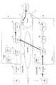
図1は、比較例としての3GPPの移動通信システムの一例であるLTE,LTE−Aに基づく移動通信システム(「LTE網」という)の構成例を示す図である。図1には、無線端末(User Equipment(UE)と呼ばれる)1がLTE網を介して通信相手(correspondent node)であるインターネット(Internet)2上のサーバ(Server)3とデータ通信をするケースが例示されている。<Configuration example of mobile communication system (comparative example)>
FIG. 1 is a diagram illustrating a configuration example of a mobile communication system (referred to as an “LTE network”) based on LTE and LTE-A, which is an example of a 3GPP mobile communication system as a comparative example. FIG. 1 shows a case where a wireless terminal (called User Equipment (UE)) 1 performs data communication with a
LTE網は、無線網とコア網とを有し、無線網には、無線基地局(「eNodeB」と呼ばれる。以下「基地局」と表記)4が配置される。コア網5には、Mobility Management Entity(MME)6,Home Subscriber Server(HSS)7,Serving GateWay(S−
GW)8、Packet data network Gateway(P−GW)9,サービス網(service NW(NetWork))10が配置される。The LTE network includes a radio network and a core network, and a radio base station (referred to as “eNodeB”, hereinafter referred to as “base station”) 4 is arranged in the radio network. The
GW) 8, Packet data network Gateway (P-GW) 9, and service network (service NW (NetWork)) 10.
MME6は、無線端末(UE)の呼制御、S−GWおよびP−GWの選択などを行う。HSS7は加入者に関する情報のデータベースを保持しており、UE1の認証および位置登録に使用される。 The MME 6 performs call control of a radio terminal (UE), selection of S-GW and P-GW, and the like. The HSS 7 holds a database of information about subscribers and is used for authentication and location registration of UE1.
S−GW8は、基地局4を介して受信されるUEからのトラフィックをP−GWに転送する。P−GW9は、インターネット2のような外部網(パケットデータネットワーク(PDN)と呼ばれる)との接続点となるゲートウェイであり、S−GW8からのトラフィックをサービス網10へ送る。 The S-GW 8 transfers traffic from the UE received via the
サービス網10は、移動通信システムを提供する通信事業者(「キャリア」という)が独自に設定した網であり、キャリアがポリシ−に従って設定した所定のネットワークサービスが実行される。 The
基地局4は、地理的に分散した状態で、複数台設置される。図1では、1つの基地局4を例示している。また、S−GW8,P−GW9,サービス網10は、図1では1つずつ図示されているが、S−GW8,P−GW9,サービス網10のそれぞれは、コア網5において複数台設けられる。 A plurality of
UE1とサーバ3との間のトラヒックは、次のような経路を流れる。UE1からのトラヒックは、基地局4を通ってS−GW8に転送される。S−GW8は基地局4から受信したトラヒックをP−GW9へ転送する。P−GW9はS−GW8から受信したトラヒックをサービス網10へ転送する。 Traffic between UE1 and
このとき、P−GW9は、トラヒックに関して所定の動作を行う。例えば、P−GW9は、トラヒックの通過量(データ量)を計上する。或いは、P−GW9は、トラフィックの通過量(データ量)に応じて通信速度を制限する。但し、P−GW9の所定動作は、こ
れらに限定されない。At this time, the P-
サービス網10には、UE1へ提供する所定のネットワークサービスに係る様々な通信機器(装置)が設置される。通信機器(装置)は、インターネット2向けのゲートウェイ(Gateway)、即ち、交換機11を介してインターネットとサービス網(サービス網)1
0とを接続するゲートウェイを含む。さらに、サービス網10は、ウェブキャッシュサーバ(Web Cache Server),年齢制限などに伴う処理を行うコンテンツフィルタリングサーバ,メールサーバ,などから選択される少なくとも1つの通信機器(装置)を含むことができる。In the
Including a gateway connecting 0. Furthermore, the
但し、サービス網10に含まれる通信機器(装置)は、これらに制限されず、UE1に提供するネットワークサービスの種別を考慮して決定される。なお、本実施形態では、サービスの種別は、サービスを提供するサービス網10の種別として扱われ、サービス網10とリンクされたP−GWのアドレスを以て識別される。 However, the communication devices (devices) included in the
MME6は、UE1がLTE網に接続する(呼を確立する)場合に、UE1が利用するサービス網10に応じたP−GW9を選択する。複数のサービス網10が設けられる場合、各サービス網10に対応するP−GW9が予め設定される。 The
UE1は、LTE網への接続時にMME6によって選択されたP−GW9の利用を、LTE網から切断されるまで継続する。また、MME6は、UE1がLTE網に接続するとき、UE1の位置に応じたS−GW8を選択する。さらに、MME6は、UE1がLTE網に接続された後、UE1の移動に応じてS−GW8を再選択し、トラフィックの経路を切り替える。 The
このようにして、MME6がUE1に応じたS−GW8およびP−GW9を選択することによって、UE1の通信経路が設定される。P−GW9とサービス網10との間の通信経路は、例えばP−GW9が有する設定ファイルなどを用いて静的に設定(決定)される。 Thus, the communication path of UE1 is set when MME6 selects S-GW8 and P-GW9 according to UE1. The communication path between the P-
UE1は、現在加入している通信事業者(キャリア:以下、「第1キャリア」という)のLTE網のサービスエリア外において、第1キャリアと提携した他の通信事業者(以下、「第2キャリア」という)のLTE網を用いたローミングを行うことができる。UE1について、第1キャリアのLTE網はホーム網であり、第2キャリアのLTE網は在圏網(visited NW)である。 UE1 is connected to another carrier (hereinafter referred to as “second carrier”) in cooperation with the first carrier outside the service area of the LTE network of the currently subscribed carrier (carrier: hereinafter referred to as “first carrier”). Roaming using the LTE network. For UE1, the LTE network of the first carrier is a home network, and the LTE network of the second carrier is a visited network (visited NW).
図2は、UE1が在圏網(第2キャリアのLTE網(「第2キャリア網」ともいう)に3GPPで規定されたホームルーテッドでローミングしたときのデータ通信経路を示す。データ通信経路(トラヒックの経路)は、太線矢印で示される。 2 shows a data communication path when UE1 roams in a visited network (LTE network of a second carrier (also referred to as “second carrier network”) with home route specified by 3GPP. Are indicated by bold arrows.
図2において、在圏網は、ホーム網と同様に、第2キャリアの無線網を形成する基地局4aと、第2キャリアのコア網5aとを含む。コア網5aは、MME6aと、S−GW8aと、P−GW9aと、サービス網10aとを含む。サービス網10aは、交換機11aを介してインターネット2に接続される。なお、コア網5aのHSSは図示を省略してある。また、図2中の“(H)”は、通信機器がホーム網(第1キャリア)に属することを示し、“(V)”は、通信機器が在圏網(第2キャリア)に属することを示す。 In FIG. 2, the visited network includes a
ホームルーテッドが実施される場合、UE1から送出されるトラヒックは、在圏網(コア網5a)のS−GW8aからローミング事業者用のネットワークであるGRX/IPX
(GPRS Roaming eXchange/IP eXchange)12を経由し、ホーム網(コア網5)内のP−G
W9に転送される。トラヒックは、最終的にサービス網10からインターネット2を経てサーバ3に到達する。ホームルーテッドでは、ローミング端末であるUE1の通信経路が一旦ホーム網に戻り、インターネット2(外部網)に抜ける。このような通信経路の設定は、非効率である。例えば、ホーム網が日本にあり、在圏網およびサーバ3がアメリカにある場合では、UE1のデータ通信経路は、アメリカから一旦日本に戻り、インターネット2を介して再びアメリカに戻ることになる。When home routed is implemented, traffic sent from UE1 is GRX / IPX which is a network for roaming operators from S-
(GPRS Roaming eXchange / IP eXchange) 12 through PG in the home network (core network 5)
Transferred to W9. The traffic finally reaches the
3GPPでは、ホームルーテッドの他に、ローカルブレイクアウト(local breakout)と呼ばれるローミングの方式が規定されている。図3は、図2に示した第2キャリア網を用いて、ローカルブレイクアウトにてUE1がローミングするときのデータ通信経路を示す。ローカルブレイクアウトでは、UE1のトラフィックが通過するP−GWとして、ホーム網のP−GW9ではなく、在圏網内のP−GW9が選択される。トラフィックは、第2キャリアのサービス網10a,インターネット2を経てサーバ3に到達する。 In 3GPP, in addition to home routed, a roaming method called local breakout is defined. FIG. 3 shows a data communication path when UE1 roams in a local breakout using the second carrier network shown in FIG. In the local breakout, the P-
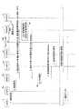
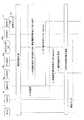
図4は、ローカルブレイクアウトの実施時におけるP−GWの選択手順の説明図である。図4において、P−GWの選択手順は、以下の通りである。 FIG. 4 is an explanatory diagram of a P-GW selection procedure when local breakout is performed. In FIG. 4, the selection procedure of P-GW is as follows.
[手順1]
UE1は、第2キャリアのLTE網にローミングする場合には、最初に、第2キャリアのLTE網への接続要求のメッセージを基地局4aを介してMME6aへ送信する(図4<1>)。接続要求のメッセージには、APN(Access Point Name)と、加入者IDなど
が含まれる。APNは、UE1の接続先の識別子であり、例えば、サービス網10の識別子である。図4の例では、APNとして、サービス網10aの識別子である“APN#b”が接続要求に含まれていると仮定する。[Procedure 1]
When roaming to the LTE network of the second carrier, the
[手順2]
MME6aは、接続要求を受け取ると、第1キャリアのHSS7に対し、UE1の認証要求を送信する(図4<2>)。[Procedure 2]
Upon receiving the connection request, the
[手順3]
HSS7は、認証要求に含まれるUE1の加入者IDに対応する加入者情報をデータベースから検索し、UE1との間で認証処理を実行する。HSS7は、認証結果を含む応答メッセージをMME6aへ返信する(図4<3>)。[Procedure 3]
The
[手順4]
MME6aは、認証が成功した場合、UE1のトラヒックを転送する第2キャリアのS−GW(図4中のS−GW8a)を選択するとともに、UE1から受信したAPN(APN#b)に基づく名前解決要求のメッセージをDomain Name System (DNS)サーバ1
3に送信する(図4<4>)。[Procedure 4]
When the authentication is successful, the
3 (FIG. 4 <4>).
[手順5]
DNSサーバ13は、APN(APN#b)に対応するP−GW9aのIPアドレス(Addr#b)をMME6aに返送する(図4<5>)。[Procedure 5]
The
[手順6]
MME6aは、手順5で選択したS−GW8aに対し、UE1のトラヒックを転送するP−GW9aのIPアドレスを通知する(図4<5>)。これによって、S−GW8aは、MME6aから指定されたP−GW9aとUE1のための通信経路をセットアップする。このとき、P−GW9aとサービス網10aとの間の通信経路は前述の通り静的に設定される。当該セットアップの通信手順、及び、以降のUE1の接続処理(呼設定手順)は
、 “3GPP TS23.401”の記載された規定に従ってなされる。ここでは、手順の詳細の説明は省略する。[Procedure 6]
The
以上説明した手順1〜手順6によって、UE1は、ホーム網を経由することなく通信相手(サーバ3)とデータ通信を行うことができる。 Through the
ローカルブレイクアウトでは、UE1とサーバ3とのデータ通信用の通信経路を形成するために、第2キャリアのLTE網(「第2キャリア網」ともいう)の設備(S−GW8a,P−GW9a,サービス網10a)を用いる。このため、UE1のデータ通信に関してなされる制御の内容や収集される情報の種別などが第2キャリアのポリシーに依存する。 In the local breakout, in order to form a communication path for data communication between the
このため、UE1がローミングをしない場合や、ホームルーテッドを実施した場合において、UE1に対して実施されるデータ通信の制御(アクセス制御、帯域制御等)やログ情報の収集が必ずしも第2キャリア網で実施されるとは限らない。従って、ローミングの場合には、UE1に係る制御の内容が一部に限定されたり、UE1に係るデータ通信に関して取得できる情報が限定されたりする可能性があった。 For this reason, when UE1 does not roam or when home routed, data communication control (access control, bandwidth control, etc.) and log information collection performed on UE1 are not necessarily performed by the second carrier network. Not necessarily implemented. Therefore, in the case of roaming, there is a possibility that the content of control related to UE1 is limited to a part or information that can be acquired regarding data communication related to UE1 may be limited.
本発明の実施形態では、上記したホームルーテッドおよびローカルブレイクアウトの欠点を回避することが可能な移動通信システムについて説明する。 In the embodiment of the present invention, a mobile communication system capable of avoiding the drawbacks of home routed and local breakout described above will be described.
<実施形態に係る移動通信システムの構成例>
実施形態に係る移動通信システムでは、Network Functions Virtualization(NFV)技術を利用して、第2キャリアのサービスエリア(例えば第2キャリア網)内に第1キャリアのネットワーク設備(通信機器およびサービス網)を設置する。第2キャリア網において、第1キャリアのネットワーク設備は、例えば、第2キャリアのネットワーク設備が設置される局舎内に配置される。<Example of Configuration of Mobile Communication System According to Embodiment>
In the mobile communication system according to the embodiment, network facilities (communication equipment and service network) of the first carrier are provided in the service area (for example, the second carrier network) of the second carrier using Network Functions Virtualization (NFV) technology. Install. In the second carrier network, the network equipment of the first carrier is arranged, for example, in a station where the network equipment of the second carrier is installed.
NFV技術とは、ネットワークを制御する通信機器の機能をソフトウェアとして実装し、汎用サーバ上に生成される仮想マシン(VM)上で実行する方式である。本実施形態では、第1キャリアのS−GW,P−GW,サービス網を形成する装置が有するネットワーク機能がソフトウェア化(仮想化)される。そして、汎用サーバ上に生成される仮想マシン上で、第1キャリアのS−GW,P−GW,サービス網を形成する装置としての仮想化ネットワーク機能(VNF: Virtualized Network Function)が動作する。 The NFV technology is a method in which the function of a communication device that controls a network is implemented as software and executed on a virtual machine (VM) generated on a general-purpose server. In this embodiment, the network functions of the devices forming the S-GW, P-GW, and service network of the first carrier are softwareized (virtualized). Then, on the virtual machine generated on the general-purpose server, a virtual network function (VNF) as a device forming the S-GW, P-GW, and service network of the first carrier operates.
例えば、汎用サーバには、ハイパバイザと呼ばれる仮想マシンを生成するためのミドルウェアが実装され、さらに、S−GW,P−GW,サービス網として動作するVNFのアプリケーションプログラムが実装される。汎用サーバが備えるプロセッサ(例えばCentral Processing Unit(CPU))がハイパバイザおよびアプリケーションプログラムを実
行することによって、汎用サーバは、S−GW,P−GW,サービス網が有するネットワーク機能(インターネット2と接続するゲートウェイなどの機能)を発揮することができる。For example, middleware for generating a virtual machine called a hypervisor is mounted on the general-purpose server, and further, an S-GW, a P-GW, and a VNF application program that operates as a service network are mounted. A processor (for example, Central Processing Unit (CPU)) included in the general-purpose server executes a hypervisor and an application program, so that the general-purpose server has a network function (gateway for connecting to the Internet 2) included in the S-GW, P-GW, and service network. Etc.).
なお、1つの汎用サーバがS−GW,P−GW,およびサービス網として動作するようにこれらのVNFが実装されても良く、S−GW,P−GW,サービス網が個別の汎用サーバに実装されても良い。或いは、S−GW,P−GW,サービス網のうちの二つが或る汎用サーバに実装され、残りが別の汎用サーバに実装されるようにしても良い。また、1つの汎用サーバに実装されるS−GW,P−GW,サービス網のそれぞれの数は任意である。 These VNFs may be mounted so that one general-purpose server operates as an S-GW, P-GW, and service network, and the S-GW, P-GW, and service network are mounted on individual general-purpose servers. May be. Alternatively, two of the S-GW, the P-GW, and the service network may be mounted on a general server, and the rest may be mounted on another general server. The number of S-GWs, P-GWs, and service networks mounted on one general-purpose server is arbitrary.
図5は、第1キャリアのP−GWおよびサービス網を第2キャリア網で仮想化した例を示す。第2キャリア網(コア網5a)がNFVに対応することによって、これまでホームルーテッドの実施時に使用されていたP−GW9およびサービス網10のネットワーク機能を仮想マシン(VM)上で動作させる。これにより、第2キャリア網に仮想のP−GW9Aおよび仮想のサービス網10Aが第2キャリア網(第2キャリアのサービスエリア)に配置された状態となる。 FIG. 5 shows an example in which the P-GW of the first carrier and the service network are virtualized by the second carrier network. Since the second carrier network (
この場合、MME6aがUE1の接続要求(APN(APN#a))に対応するP−GWとしてP−GW9Aを選択し、P−GW9AのIPアドレス(addr#a)をS−GW8aに通知することで、S−GW8,P−GW9A,サービス網10Aを経由するUE1の通信経路が構築される。このように、MME6aは、通信経路の形成を制御する。 In this case, the
図6は、第1キャリアのS−GW,P−GWおよびサービス網を第2キャリア網で仮想化した例を示す。図6の例では、第1キャリアのS−GW8,P−GW9,およびサービス網10のそれぞれが有するネットワーク機能が第2キャリア網(コア網5a)で仮想化されている。これにより、第1キャリアのS−GW8A,P−GW9A,およびサービス網10Aが第2キャリア網に設置された状態となる。 FIG. 6 shows an example in which the S-GW, P-GW and service network of the first carrier are virtualized by the second carrier network. In the example of FIG. 6, the network functions of the first carrier S-
MME6aは、UE1からの接続要求の受信時に、S−GW8Aを選択し、P−GW9AのIPアドレスをS−GW8Aに通知する。これによって、S−GW8A,P−GW9A,サービス網10Aの通信経路がコア網5aで形成される。 When receiving the connection request from UE1,
図5や図6に示した例によれば、UE1のデータ通信の通信経路は、P−GW9およびサービス網10を経由しないので、ホームルーテッドのように通信経路が非効率となるのを回避することができる。また、通信経路が第1キャリアのP−GW9Aおよびサービス網10Aを通過することで、通信経路がP−GW9およびサービス網10を通過する場合と同様の制御やデータ収集を行うことが可能となる。 According to the examples shown in FIG. 5 and FIG. 6, the communication path for data communication of UE1 does not pass through the P-
図5や図6のようなローミングでは、UE1のデータ通信経路の形成のために、第1キャリアのネットワーク機能を第2キャリア網においてVNFとして動作させる。そして、UE1が第2キャリア網へローミングした際に、UE1がこれらのVNFを使用してデータ通信を行う。このため、予め第2キャリア網(コア網5a)に第1キャリアのVNFを配備しておき、UE1が第2キャリア網に接続する際に配備されたVNFが選択されるための設定を行う。また、図6の例に示したように、S−GWを第1キャリアのVNFとして動作させる場合には、UE1が基地局間を移動するときに、必要に応じてS−GWが再選択されるようにする。 In roaming as shown in FIG. 5 and FIG. 6, the network function of the first carrier is operated as VNF in the second carrier network in order to form the data communication path of UE1. When UE1 roams to the second carrier network, UE1 performs data communication using these VNFs. For this reason, the VNF of the first carrier is deployed in advance in the second carrier network (
なお、インターネット2は、「外部網」の一例である。MME6aは、「端末の通信経路を制御する装置」の一例である。S−GW8A,P−GW9A,サービス網10Aのそれぞれは、「第1キャリアの通信機器」の一例である。HSS7は、「加入者情報の管理装置」の一例である。 The
<通信経路の制御システムの構成例>
図7は、第2キャリア網に第1キャリアのネットワーク設備(VNF)を配備してこれを用いた通信経路を形成させるシステム(通信経路の制御システム)の構成例を示す図である。通信経路の制御システムは、VNF配備サーバ21と、運用システム22と、VNF選択サーバ23とを含む。VNF選択サーバ23は、「サーバ」,「情報処理装置」の一例である。運用システム22は、「他の装置」の一例である。<Configuration example of communication path control system>
FIG. 7 is a diagram illustrating a configuration example of a system (communication path control system) in which a first carrier network facility (VNF) is provided in a second carrier network and a communication path using the first carrier network equipment (VNF) is formed. The communication path control system includes a
第1キャリアのVNFを第2キャリアの局舎(サービスエリア)内に配備しておき、U
E1が第2キャリア網に接続する際、MME6aがVNF選択サーバ23に使用するVNFを問い合わせる。これによって、UE1に関するデータ通信経路を形成するために配備済みVNF(S−GW8A,P−GW9A)が選択されるようにする。The VNF of the first carrier is deployed in the station (service area) of the second carrier, and U
When E1 connects to the second carrier network, the
図8は、VNF配備サーバ21、運用システム22、およびVNF選択サーバ23の機能ブロック構成例を示す図である。図8において、VNF配備サーバ21は、VNF配備要求受信部211と、VNF配備の実行部212と、VNF配備結果の通知部213とを含む。 FIG. 8 is a diagram illustrating a functional block configuration example of the
VNF配備要求受信部211は、運用システム22からVNF配備要求を受信する。VNF配備実行部212は、VNF配備受信部211で受信したVNF配備要求に対応するVNFを第2キャリアの局舎内の汎用サーバ15上に配備する。 The VNF deployment
VNF配備結果通知部213は、VNFの配備結果を運用システム22に通知する。通知内容は配備されたVNF(S−GW8A, P−GW9A)に割り当てられたアドレスを含む。アドレスは、例えばIPアドレスである。但し、IPアドレス以外のアドレスや識別子が適用され、別途対応テーブルを用いてアドレスや識別子からIPアドレスが割り出される構成が採用されても良い。VNFアドレス(S−GWアドレス,P−GWアドレス)は、「第1キャリアの通信機器を示す情報」の一例である。 The VNF deployment
運用システム22は、VNF配備要求の送信部221、VNF配備結果の受信部222、および配備済VNF情報の送信部223を含む。VNF配備要求の送信部221は、第1キャリアのポリシーに従って、配備要求するVNFに関する情報をVNF配備サーバ21に送信する。 The
VNF配備結果の受信部222は、VNFの配備結果をVNF配備サーバ21から受信する。配備済VNF情報の送信部223は、VNF配備結果の受信部222で受信された配備済みのVNF(S−GW8A, P−GW9A)のIPアドレス、およびVNFを配備した通信事業者(第1キャリア)のID(第1キャリアID:第1キャリアの識別子)をVNF選択サーバ23に送信する。 The VNF deployment
VNF選択サーバ23は、配備済VNF情報の受信部231、配備済みVNF情報の保存部232、VNFアドレス問い合わせの受信部233、VNFアドレスの検索部234、およびVNFアドレスの送信部235を含む。 The
配備済みVNF情報の受信部231は、運用システム22から受信したVNF(S−G
W8A, P−GW9A)のIPアドレスと、第1キャリアIDとを配備済みVNF情報の
保存部232に保存(記憶)する。The deployed VNF
W8A, P-GW9A) and the first carrier ID are stored (stored) in the
VNFアドレス問い合わせの受信部233は、MME6aからUE1のデータ通信に使用するVNFのIPアドレスの問い合わせを受信する。この問い合わせは、第1キャリアIDを含む。問い合わせに含まれる第1キャリアIDは、例えば、MME6aがUE1からの接続要求に含まれた第1キャリアIDを取得することによって得られる。或いは、MME6aがHSS7などの他の通信機器から得ることもできる。 The VNF address
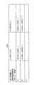
配備済VNF情報の保存部232は、データベースを有する。データベースの検索には、第1キャリアIDが検索鍵として使用される。図9は、保存部232で保存されるデータベース232Aのデータ構造例を示す。図9に示すように、データベース232Aは、第1キャリアIDと関連づけて、S−GWおよびP−GWのアドレスを記憶する。なお、図9では、サービス網10Aとして動作するVNFに関する情報を保存しないものとする
。検索鍵は、「端末に関係する鍵」の一例である。The deployed VNF
VNFアドレスの検索部234は、VNFアドレス問い合わせの受信部233で問い合わせが受信された場合に、配備済VNF情報の保存部232を参照し、第1キャリアIDに対応するVNF(S−GW,P−GW)のIPアドレスを検索(検出)する。 The VNF
このとき、第1キャリアIDに対応する複数のVNFのIPアドレスが登録されている場合には、複数のIPアドレスの1つがランダムに選択(検索)される。或いは、所定の優先順位に従って複数のIPアドレスの1つが選択(検索)されても良い。なお、選択対象のVNFがS−GWである場合には、UE1と接続された基地局4aが属するエリアを示すTAC(Tracking Area Code: 基地局をグルーピングしたID相当のコード)を元にS−GWを選択することも考えられる。TACは、第1キャリアIDの代わりに検索鍵として使用されても良く、第1キャリアIDとともに検索鍵として使用されても良い。TACは、「エリア識別子」の一例である。第1キャリアIDおよびTACのそれぞれは、「検索鍵」の一例である。 At this time, when a plurality of VNF IP addresses corresponding to the first carrier ID are registered, one of the plurality of IP addresses is randomly selected (searched). Alternatively, one of a plurality of IP addresses may be selected (searched) according to a predetermined priority order. When the VNF to be selected is S-GW, S-based on the TAC (Tracking Area Code: code corresponding to ID grouping base stations) indicating the area to which the
VNFアドレスの送信部235は、VNFアドレスの検索部234で検索されたVNFのIPアドレスをMME6aに送信(供給)する。これに対し、検索部234の検索の結果、対応するVNFアドレスがなかった場合は、送信部235は、対応VNFアドレスがない旨をMME6aに通知する。 The VNF
図10は、第1キャリアのVNFを第2キャリアの局舎に配備し、VNF選択サーバ23に配備済みのVNF情報が登録されるまでの流れを示す図である。図10において、第1に、運用システム22は、VNF配備サーバ21に対し、VNFを第2キャリアの局舎上に配備するよう指示する(配備要求を送信する)(図10<1>)。 FIG. 10 is a diagram illustrating a flow from when the VNF of the first carrier is deployed in the station of the second carrier and the deployed VNF information is registered in the
第2に、VNF配備サーバ21は、運用システム22からの指示に従って、配備要求に対応するVNFを第2キャリアの局舎に配備する(図10<2>)。図10の例では、S−GW8A,P−GW9A,サービス網10Aが配備された例を示す。S−GW8Aは配備しない場合もある。 Second, the
第3に、VNF配備サーバ21は、配備したVNF(S−GW,P−GW)に割当てられたIPアドレス(VNFアドレス)を運用システムに通知する(図10<3>)。第4(最後)に、運用システム22は、VNF選択サーバ23にVNFアドレス、および第1キャリアIDを通知し(図10<4>)、VNF選択サーバ23は、これをデータベース232Aに保存する。 Third, the
上記した実施形態によれば、仮想化されたP−GW9Aおよびサービス網10Aが第2キャリアのサービスエリアに配備され、これらを通過してインターネット2へ至るデータ通信経路が形成される(図5)。或いは、仮想化されたS−GW8A,P−GW9A,サービス網10Aが第2キャリアのサービスエリアに配備され、これらを通過してインターネット2へ至るデータ通信経路が形成される(図6)。これらによって、ホームルーテッドのように、非効率なデータ通信経路が形成されることを回避することができる。なお、データ通信経路を流れるデータは、テキスト,画像,動画,音声などの様々なデータを含む。 According to the above-described embodiment, the virtual P-
<変形例>
図8〜図10を用いて説明した例では、VNF選択サーバ23は、UE1を使用している加入者の契約状況を考慮しない。契約状況は、第2キャリアの局舎上に配備されている第1キャリアのVNFを使用してよいか否かを示す情報、UE1がAPNにより指定する
サービス網の種別を示す情報を含む。<Modification>
In the example described with reference to FIGS. 8 to 10, the
このため、第2キャリア網に接続した際に第1キャリアのVNFが配備されている第2キャリア網に第1キャリアのUEが接続した場合には、UE1の加入者の契約状況に依らず、UEがVNFを使用する。また、図8〜図10を用いて説明した例では、第1キャリアのUEが第2キャリア網にローミング接続する場合において、UEがAPNにより指定するサービス網の種別に依らず、第2キャリアの局舎に配備されたサービス網が使用される。このため、以下のような変形例が考えられる。 For this reason, when the UE of the first carrier is connected to the second carrier network where the VNF of the first carrier is connected when connected to the second carrier network, regardless of the contract status of the subscriber of UE1, The UE uses VNF. Further, in the example described with reference to FIGS. 8 to 10, when the UE of the first carrier roams to the second carrier network, regardless of the type of the service network designated by the UE by the APN, The service network deployed in the station building is used. For this reason, the following modifications can be considered.
<<変形例1>>
図11は、通信経路の制御システムの変形例を示す図である。UEの加入者の契約状況を考慮する場合、VNF選択サーバ23は、さらに以下のような動作を行う。
(a)VNFアドレス問い合わせの受信部233は、問い合わせに含まれたUEの加入者ID(UE(加入者)の識別子)を受信する。加入者IDは「端末の識別子」の一例である。<<
FIG. 11 is a diagram illustrating a modification of the communication path control system. When considering the contract status of the subscriber of the UE, the
(A) The VNF address
(b)VNFアドレスの検索部234は、加入者IDを用いて、第1キャリアのHSS7に対し、第2キャリアの局舎に配備されているVNFを使用してよいか否かを問い合わせる。HSS7は、VNF選択サーバ23から得た加入者IDに対応する加入者情報を検索する。加入者情報には、当該加入者がVNFの使用を許されているか否かを示す情報が含まれている。HSS7は、当該情報を確認することで、UE1に対するVNFの使用可否を判定する。HSS7は、VNF選択サーバ23に対し、判定結果(VNFの使用可、又はVNF使用不可)を返信する。(B) Using the subscriber ID, the VNF
(c)VNFアドレスの検索部234は、HSS7に対する問い合わせの結果、VNFの使用可を示す通知をHSS7から受信した場合には、保存部232を参照し、該当VNFのアドレスを検索する。これに対し、HSS7からVNF使用不可の通知がVNF選択サーバ23で受信された場合には、VNFアドレスの送信部235は、VNFの使用不可の旨をMME6aに通知する。この場合、MME6aは、例えば、通常のローミング方式(ホームルーテッドまたはローカルブレイクアウト)でデータ通信経路を形成する。(C) As a result of the inquiry to the
<<変形例2>>
また、UEがAPNにより指定するサービス網の種別を考慮する場合、VNF選択サーバ23は、以下のように変形される。図12および図13は、保存部232に記憶されるデータベースのデータ構造例を示す。<<
Further, when considering the type of service network designated by the UE by the APN, the
図12および図13に示すように、データベースは、P−GWのIPアドレスを検索するためのデータベース232Bと、S−GWのIPアドレスを検索するためのデータベース232Cとに分離される。 As shown in FIGS. 12 and 13, the database is divided into a
図12に示すように、データベース232Bには、第1キャリアIDおよびAPNに対応するP−GWのIPアドレスが検索される。P−GWのIPアドレスは、APNにて指定されるサービス網の種別に応じて用意される。APNは「サービス網の識別子」の一例である。 As shown in FIG. 12, the
図13に示すように、データベース232Cには、第1キャリアIDに対応するS−GWのIPアドレスが記憶される。S−GWは、APNに依存することなく選択されるからである。 As illustrated in FIG. 13, the IP address of the S-GW corresponding to the first carrier ID is stored in the
図12および図13に示したデータベース232Bおよびデータベース232Cが使用
される場合、例えば、図8に示すVNF選択サーバ23は、上述した動作に加えて以下のような動作を行う。When the
すなわち、VNF選択サーバ23におけるVNFアドレス問い合わせの受信部233は、MME6aからの問い合わせに含まれるAPNを取得する。APNは、UEによって指定され、例えば、UEの接続要求に含まれている。 That is, the VNF address
VNFアドレスの検索部234は、問い合わせ対象のVNFがP−GWであれば、保存部232のデータベース232Bを参照し、問い合わせに含まれた第1キャリアIDおよびAPNに対応するVNF(P−GW)のIPアドレスを読み出す。すなわち、第1キャリアIDおよびAPNがデータベース232Bの検索鍵として用いられる。APNは「検索鍵」の一例である。 If the inquiry target VNF is P-GW, the VNF
これに対し、問い合わせ対象のVNFがS−GWおよびP−GWであれば、上記したP−GWのIPアドレスの検索(読み出し)に加えて、データベース232Cから第1キャリアIDに対応するS−GWのIPアドレスを検索する(読み出す)。 On the other hand, if the VNFs to be inquired are S-GW and P-GW, in addition to the search (reading) of the IP address of the P-GW, the S-GW corresponding to the first carrier ID from the
上記した変形例2の構成は、変形例1の構成と組み合わせることができる。これにより、加入者の契約状況およびサービス網の種別の双方を考慮したVNF選択が可能となる。 The configuration of
変形例2によれば、APNに応じたサービス網10AとUE1とが接続されるように、P−GW9AのIPアドレスが決定される。これによって、UE1に対し、ホーム網で提供される所定のネットワークサービスと同等のネットワークサービスを提供することができる。 According to the second modification, the IP address of the P-
また、実施形態によれば、ローミング時のデータ通信に第1キャリアのネットワーク設備が使用される。このため、UE1のデータ通信に関して、ホーム網で実施されているのと同様の制御(例えば、アクセス制御や帯域制御など)や情報収集(例えば、ログ情報の収集)を行うことができる。 Further, according to the embodiment, the network equipment of the first carrier is used for data communication during roaming. For this reason, it is possible to perform the same control (for example, access control and bandwidth control) and information collection (for example, collection of log information) as those performed in the home network for the data communication of UE1.
なお、実施形態では、第1キャリアのネットワーク設備(通信機器ないし装置)として、汎用サーバ上で動作するVNFが示されているが、通信機器ないし装置がVNF(仮想ネットワーク機能)であることは必須要件ではない。すなわち、第2キャリアのサービスエリアに配置される第1キャリアのネットワーク設備(通信機器)は、実装置であっても良い。 In the embodiment, VNF operating on a general-purpose server is shown as the network equipment (communication equipment or device) of the first carrier. However, it is essential that the communication equipment or device is VNF (virtual network function). It is not a requirement. That is, the network equipment (communication equipment) of the first carrier arranged in the service area of the second carrier may be an actual device.
<ハードウェア構成例>
図14は、VNF選択サーバ23として動作する情報処理装置(コンピュータ)100のハードウェア構成例を示す図である。情報処理装置として、例えば、専用のサーバマシン、或いは汎用のコンピュータ(例えば、パーソナルコンピュータ(PC),ワークステーションなど)などを適用することができる。<Hardware configuration example>
FIG. 14 is a diagram illustrating a hardware configuration example of the information processing apparatus (computer) 100 that operates as the
情報処理装置100は、バスBを介して相互に接続されたプロセッサ101,主記憶装置102,補助記憶装置103,入力装置104,出力装置105,およびネットワークインタフェース(NIF)106を含む。 The
入力装置104は、例えば、キーボード、マウス等のポインティングデバイス等である。入力装置104から入力されたデータは、プロセッサに与えられる。出力装置105は、プロセッサ101の処理の結果を出力する。出力装置105は、例えば、スピーカ等の音声出力装置、ディスプレイ、プリンタを含む。 The input device 104 is, for example, a pointing device such as a keyboard and a mouse. Data input from the input device 104 is provided to the processor. The
NIF106は、ネットワークとの情報の入出力を行うインタフェース回路である。NIF106は、有線のネットワークと接続するインタフェース、無線のネットワークと接続するインタフェースとの少なくとも一方を含む。NIF106は、例えば、ネットワークインタフェースカード(NIC)、LAN(Local Area Network)カード、無線LANカード等である。NIF106で受信されたデータ等は、プロセッサ101に渡される。 The
補助記憶装置103は、様々なプログラムや、各プログラムの実行に際してプロセッサ101が使用するデータを格納する。補助記憶装置103は、例えば、EPROM(Erasable Programmable ROM)、ハードディスクドライブ(Hard Disk Drive)、フラッシュメモリ
、Solid State Drive(SSD)等の不揮発性のメモリである。補助記憶装置103は、
例えば、オペレーティングシステム(OS)、データ蓄積先決定プログラム、その他様々なアプリケーションプログラムを記憶する。補助記憶装置103は、USBメモリのような可搬記録媒体や、CD、DVDのようなディスク記録媒体を含み得る。The
For example, an operating system (OS), a data storage destination determination program, and various other application programs are stored. The
主記憶装置102は、プロセッサ101に、補助記憶装置103に格納されているプログラムをロードする記憶領域および作業領域を提供したり、バッファとして用いられたりする。主記憶装置102は、例えば、Random Access Memory(RAM)のような半導体メモリを用いて形成される。主記憶装置102はRead Only Memory(ROM)を含む場合もある。 The
プロセッサ101は、例えば、Central Processing Unit(CPU)、或いはマイクロ
プロセッサ(MPU)である。プロセッサ101は、補助記憶装置103に記憶された各種のプログラムを主記憶装置102にロードして実行する。これによって、情報処理装置100がVNF選択サーバとして動作するための様々な処理を実行する。プロセッサは、1つに限られず、複数備えられてもよい。The
プロセッサ101は、「制御装置」の一例である。主記憶装置102および補助記憶装置103のそれぞれは、「記憶装置」、「コンピュータ読み取り可能な記録媒体」の一例である。また、プロセッサ101によって実行される処理の一部又は全部は、半導体デバイスを用いたハードウェアロジックによってなされるようにしても良い。半導体デバイスは、例えば、Field Programmable Gate Array(FPGA)のようなプログラマブルロジ
ックデバイス(PLD),Application Specific Integrated Circuit(ASIC),Large Scale Integrated circuit(LSI),IC,ゲート回路の組み合わせ、電気・電子
回路を含む。The
プロセッサ101は、プログラムの実行によって、以下のような処理を行う。すなわち、プロセッサ101は、受信部231として、VNF情報(VPNアドレスおよび第1キャリアID)を保存部232に記憶する処理を行う。また、プロセッサ101は、受信部233として、問い合わせ(第1キャリアID,APN)を取得する処理を行う。 The
また、プロセッサ101は、検索部234として、VNFアドレス(P−GWのIPアドレス、又はS−GWおよびP−GWのIPアドレス)を保存部232から検索する処理を行う。また、プロセッサ101は、検索部234として、HSS7に問合せを行う。さらに、プロセッサ101は、送信部235としてVNFアドレスをMMEに通知する処理を行う。また、保存部232は、主記憶装置102または補助記憶装置103に記憶される。 Further, the
情報処理装置100は、VNF配備サーバ21として使用することができる。この場合、情報処理装置100の補助記憶装置103には、プロセッサ101が受信部211,V
NF配備実行部212,通知部213としての動作を行うための各種のプログラムが記憶(インストール)される。The
Various programs for performing operations as the NF
また、情報処理装置100は、運用システム22として使用することができる。この場合、情報処理装置100の補助記憶装置103には、プロセッサ101が送信部221,受信部222,送信部223としての動作を行うためのプログラムが記憶(インストール)される。 Further, the
また、情報処理装置100は、汎用サーバ15として使用することができる。この場合、情報処理装置100の補助記憶装置103には、上記したハイパバイザ,OS,VNF(S−GW,P−GW,サービス網内の装置)を実行するためのアプリケーションプログラムが記憶される。 Further, the
さらに、情報処理装置100は、MME6(6a),HSS7,S−GW8(8a),P−GW9(9a),サービス網10(10a)に含まれる装置(サーバ等),DNSサーバ13として使用することができる。 Furthermore, the
情報処理装置100がMME6(6a)として使用される場合、補助記憶装置103には、プロセッサ101の実行によって情報処理装置100がMME6(6a)として動作するための各種のプログラムが記憶される。 When the
情報処理装置100がHSS7として使用される場合、補助記憶装置103には、プロセッサ101の実行によって情報処理装置100がHSS7として動作するための各種のプログラムと、加入者データベースなどが記憶される。 When the
情報処理装置100がS−GW8(8a)として使用される場合、補助記憶装置103には、プロセッサ101の実行によって情報処理装置100がS−GW8(8a)として動作するための各種のプログラムが記憶される。 When the
情報処理装置100がP−GW9(9a)として使用される場合、補助記憶装置103には、プロセッサ101の実行によって情報処理装置100がP−GW9(9a)として動作するための各種のプログラムが記憶される。 When the
情報処理装置100がサービス網10の通信機器(装置)として使用される場合、補助記憶装置103には、プロセッサ101の実行によって情報処理装置100が当該通信機器(装置)として動作するための各種のプログラムが記憶される。 When the
なお、図8や図11に示した例では、UE1のデータ通信経路の形成の制御に第2キャリアのMME6aを使用する例が示されている。但し、第1キャリアのMMEを第2キャリアの局舎(サービスエリア)内で仮想化し、MME6aの代わりに仮想化されたMMEがVNF選択サーバ23への問い合わせおよび制御を行うようにしても良い。この場合、例えば、基地局4aが、接続されたUE1からの接続要求(発呼要求)を仮想化MMEへ転送するようにされる。 In the examples illustrated in FIG. 8 and FIG. 11, an example is shown in which the
また、図11に示した例では、HSS7が第1キャリア網(コア網5)にある例を示している。これに代えて、仮想化された第1キャリアのHSSが第2キャリアの局舎(サービスエリア)に配置され、VNF選択サーバ23がこの仮想化されたHSSに対して問合せを行うようにしても良い。 In the example shown in FIG. 11, the
<運用例>
VNF選択サーバ23は、独立した装置として設置することができる。或いは、VNF選択サーバ23は、HSS,MME,DNSサーバのそれぞれとして動作する情報処理装置(コンピュータ)に実装することもできる。実装は、例えば、VNF選択サーバ23として動作するための各種のプログラムを情報処理装置にインストールすることによってなされる。<Operation example>
The
また、配備対象のVNFとして、P−GWとサービス網を第2キャリアのサービスエリアに配備する場合、S−GWを含めて他社局舎内に配備する場合が考えられる。この場合、さらに、S−GWのアドレスを返送するVNF選択サーバ23とMMEとを同一の情報処理装置に実装し(同居させ)、P−GWのアドレスを返送するVNF選択サーバ23とHSSとを同一の情報処理装置に実装する(同居させる)ことが考えられる。すなわち、VNF選択サーバ23を、S−GWアドレス用のVNF選択サーバとP−GWアドレス用のVNF選択サーバとに分ける構成も考えられる。 In addition, when the P-GW and the service network are deployed in the service area of the second carrier as the deployment target VNF, the deployment may be performed in the other company's station including the S-GW. In this case, the
以下、運用例として、上述したパターンに関して、UE1が第2キャリア網にローミングする際の手順を示す。なお、運用例の説明では、UE1を使用している加入者の契約状況、およびUE1がAPNにより指定するサービス網の種別の両方が考慮される例について説明する。 Hereinafter, as an operation example, a procedure when UE1 roams to the second carrier network with respect to the above-described pattern is shown. In the description of the operation example, an example will be described in which both the contract status of the subscriber using the
<<運用例1>>
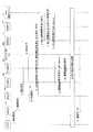
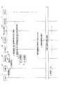
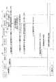
運用例1として、第2キャリアのサービスエリアに配備される対象のVNFがP−GWおよびサービス網であり(図5参照)、VNF選択サーバ23が独立した装置であるパターンにおけるローミング時の手順について説明する。図15は、運用例1のローミング手順を示すシーケンス図である。<< Operation Example 1 >>
As an operation example 1, a procedure at the time of roaming in a pattern in which the target VNF deployed in the service area of the second carrier is the P-GW and the service network (see FIG. 5), and the
(手順1)
図15において、第1キャリアの加入端末であるUE1は、在圏網(第2キャリア網)へローミングする場合には、基地局4aに接続要求(発呼要求)のメッセージを送信する。接続要求は、第1キャリアのID,加入者ID(UE1の識別子),UE1で指定されたAPNを含む。(Procedure 1)
In FIG. 15, UE1 which is a subscriber terminal of the first carrier transmits a connection request (call request) message to
(手順2〜4)
基地局4aは、MME6aにUE1から受信された接続要求を転送する(手順2)。接続要求を受信したMME6aは、第1キャリアのHSS7に対し、UE1の認証要求のメッセージを送信する(手順3)。認証要求を受信したHSS7は、UE1との間で認証処理を行い、MME6aに対して認証結果のメッセージを送信する(手順4)。(Procedure 2-4)
The
(手順4A,手順5)
認証結果を受信したMME6aは、認証が成功した場合、既存の方法によりS−GW選択処理を行う(手順4A)。また、MME6aは、第1キャリアのP−GWのIPアドレスの解決のために、VNF選択サーバ23にVNF選択要求のメッセージを送信する(手順5)。VNF選択要求は、選択対象のVNF種別がP−GWである旨,第1キャリアID,加入者ID,およびAPNを含む。(
The
(手順6)
VNF選択要求を受信したVNF選択サーバ23(VNF選択サーバ23として動作する情報処理装置100のプロセッサ101)は、VNFの使用可否(加入者情報要求)をHSS7に問い合わせる。問合せは、加入者IDを含む。(Procedure 6)
The
(手順7)
HSS7は、加入者IDを元に加入者データベースから加入者情報を検索し、加入者情報に含まれたVNF使用可否を示す情報(使用可または使用不可:加入者情報応答)をVNF選択サーバ23に応答する。(Procedure 7)
The
(手順8)
HSS7からの応答を受信したVNF選択サーバ23(プロセッサ101)は、HSS7に対する問い合わせ結果、VNFが使用可であれば、問い合わせに含まれた選択対象のVNF種別に基づき、保存部232(データベース232B(図12))を参照する。VNF選択サーバ23(プロセッサ101)は、問い合わせに含まれた第1キャリアIDおよびAPNに対応するP−GWのIPアドレス(P−GWアドレス)をデータベース232Bから読み出す(検索する)。そして、VNF選択サーバ23(プロセッサ101)は、P−GWアドレスをMME6aに送信(供給)する。(Procedure 8)
The VNF selection server 23 (processor 101) that has received the response from the
(手順9)
P−GWアドレスを受信したMME6aは、S−GW選択処理で得たS−GWアドレス(S−GWのIPアドレス)を持つS−GW8aに対し、通信経路の確立要求のメッセージを送信する。この通信経路の確立要求はP−GWアドレスを含む。(Procedure 9)
Receiving the P-GW address, the
(手順10)
通信経路の確立要求を受信したS−GW8aは、P−GWアドレスを有するP−GW9Aに対し、通信経路の確立要求のメッセージを送信する。その後、P−GW9AとAPNで指定したUE1の接続先であるサービス網10Aとの通信経路が確立される。さらに、基地局4aとUE1との間で無線経路が確立される。(Procedure 10)
The S-
その後の手順(呼確立の手順)の詳細は説明を省略する。大略すると、S−GW8aは、通信経路の確立完了をMME6aに送る。MME6aは、基地局4aに対し、UE1との無線通信経路の確立要求を与える。基地局4aとUE1との間で無線通信経路が確立されると、MME6aは、S−GW8aに対し、通信経路の更新要求を送信する。S−GW8aは、通信経路の更新処理を行うことで、S−GW8aと基地局4aとの間の通信経路と無線通信経路とを接続する。 Details of the subsequent procedure (call establishment procedure) will be omitted. In brief, the S-
また、サービス網10に含まれるゲートウェイは、交換機11aを介してインターネット2に接続し、UE1の通信相手であるサーバ3(図5)との経路を確立する。このようにして、UE1とサーバ3との間のデータ通信経路(UE1→基地局4a→S−GW8a→P−GW9A,サービス網10A→インターネット2→サーバ3)が確立される。 Further, the gateway included in the
そして、UE1は第2キャリアのサービスエリアに配置された第1キャリアの通信設備(VNF)を用いてインターネット2へ接続し、サーバ3へデータを送ることができる(手順11)。 Then, the
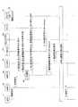
<<運用例1−1>>
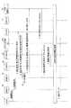
上記した運用例1の手順では、手順3と手順6との2回、HSS7にアクセスしている。HSS7へのアクセスを一回で済ませる運用例1の変形例を運用例1−1として図16を用いて説明する。<< Operation Example 1-1 >>
In the procedure of the operation example 1 described above, the
(手順1〜3)
図16において、運用例1−1における手順1および手順2は運用例1と同じである。MME6aは、HSS7に対し、UE1の認証要求と加入者情報要求とを同時に送信する(手順3)。認証要求および加入者情報要求は加入者IDを含む。(
In FIG. 16,
(手順4)
認証要求および加入者情報要求を受信したHSS7は、加入者IDを元にUE1の認証処理を行う。認証が成功すると、HSS7は、加入者情報から判定したVNFの使用可否を示す情報を認証結果とともにMME6aへ送信する。(Procedure 4)
The
(手順5)
MME6aは、HSS7に対する問合せの結果、VNFが使用可である場合には、運用例1の手順5で説明した処理と同様の処理を行う。(Procedure 5)
When the VNF is usable as a result of the inquiry to the
(手順6)
VNF選択サーバ23(プロセッサ101)は、問い合わせのあったVNFについて、保存部232を参照し、第1キャリアIDおよびAPNに対応するP−GWアドレスを検索する。VNF選択サーバ23(プロセッサ101)は、P−GWアドレスをMME6aに送信(供給)する。このように、運用例1−1では、VNFの使用可否の問い合わせが手順3で既に行われているため、運用例1における手順6および手順7の処理は行われない。(Procedure 6)
The VNF selection server 23 (processor 101) searches the P-GW address corresponding to the first carrier ID and the APN with reference to the
(手順7〜9)
その後、手順7〜9として、運用例1(図15)の手順9〜11と同様の処理が実行される。これによって、UE1がサーバ3に対してデータを送信可能となる。(Procedures 7-9)
Thereafter, as
<<運用例2>>
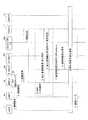
運用例2として、第2キャリアのサービスエリアに配備される対象のVNFがP−GWおよびサービス網であり(図5参照)、VNF選択サーバ23をHSS7と同居させたパターンにおけるローミング時の手順について説明する。図17は、運用例2のローミング手順を示すシーケンス図である。同居とは、HSS7として動作する情報処理装置100にVNF選択サーバ23として動作するためのプログラムを実装し、情報処理装置100がHSS7およびVNF選択サーバ23として動作することを意味する。<< Operation Example 2 >>
As operation example 2, the target VNF to be deployed in the service area of the second carrier is the P-GW and the service network (see FIG. 5), and the procedure at the time of roaming in the pattern where the
(手順1〜4)
運用例2における手順1〜4は、運用例1における手順1〜4と同様であるので説明を省略する。(
Since
(手順5)
MME6aは、認証が成功した場合、既存の方法によりS−GW選択処理を行うとともに、HSS7に対し、VNF選択要求を送信する。VNF選択要求は、VNF種別(P−GW), 第1キャリアID, 加入者ID, およびAPNを含む。VNF選択要求がHSS7に送信される。このため、運用例1と異なり、運用例1の手順6および手順7に相当する手順はない。(Procedure 5)
When the authentication is successful, the
(手順5A,手順6)
HSS7(プロセッサ101)は、加入者IDに基づき加入者情報を検索し、加入者(UE1)のVNFの使用可否を判定する(手順5A)。VNFが使用可である場合、HSS7(プロセッサ101)は、VNF選択サーバ23として動作し、保存部232を参照して第1キャリアIDおよびAPNに対応するP−GWアドレスを検索する。HSS7は、得られたP−GWアドレスをMME6aに送信(供給)する(手順6)。(
The HSS 7 (processor 101) searches the subscriber information based on the subscriber ID, and determines whether or not the VNF of the subscriber (UE1) can be used (
(手順7〜9)
運用例2の手順7〜9は、運用例1の手順9〜11と同じであるので説明を省略する。運用例2では、VNF選択サーバ23の宛先とHSS7と同じにすることができ、管理す
るアドレスを減らすことができる。HSS7は、第1キャリア網にあるため、VNF選択サーバ23を第2キャリア網やその近傍(遠隔地)に配置する場合よりも管理を容易にし得る。(Procedures 7-9)
Since the
<<運用例2−1>>
運用例2(図17)では、手順3と手順5との2回HSS7にアクセスしている。HSS7へのアクセスを一回で済ませる運用例2の変形例を運用例2−1として図18を用いて説明する。<< Operation Example 2-1 >>
In the operation example 2 (FIG. 17), the
(手順1〜3)
図18に示す手順1および手順2は、運用例2(図17)と同じであるので説明を省略する。MME6aは、UE1の認証要求とともにVNF選択要求をHSS7に送信する(手順3)。(
Since
(手順3A,手順4)
認証要求およびVNF選択要求を受信したHSS7(プロセッサ101)は、UE1の認証処理を行い、認証処理が成功すると、加入者IDを元にVNFの使用可否を判定する(手順3A)。VNFが使用可である場合、HSS7(プロセッサ101)は、VNF選択サーバ23として動作し、第1キャリアIDおよびAPNに対応するP−GWアドレスを保存部232から検索する。HSS7(プロセッサ101)は、P−GWアドレスを含む応答メッセージ(認証応答+VNF選択応答)をMME6aに送る(供給する)(手順4)。(
The HSS 7 (processor 101) that has received the authentication request and the VNF selection request performs an authentication process for the
(手順4A,手順5〜7)
MME6aは、S−GW選択処理を行う(手順4A)。その後の手順5〜7は、運用例1における手順9〜11と同じであるので説明を省略する。(
The
<<運用例3>>
運用例3では、以下のパターンにおけるローミング時の手順を説明する。すなわち、第2キャリアのサービスエリアに配備される対象のVNFがP−GWおよびサービス網である(図5参照)。また、VNF選択サーバ23とMME6aとが同一の情報処理装置100に実装されている。図19は、運用例3のローミング手順を示すシーケンス図である。<< Operation Example 3 >>
In Operation Example 3, a procedure for roaming in the following pattern will be described. That is, the target VNFs deployed in the service area of the second carrier are the P-GW and the service network (see FIG. 5). In addition, the
(手順1〜4)
図19における手順1〜4は、運用例1(図15)における手順1〜4と同じであるので説明を省略する。(
Since
(手順4A,手順5,手順6)
MME6a(プロセッサ101)は、認証が成功した場合、既存の方法によりS−GW選択処理を行う(手順4A)。さらに、MME6a(プロセッサ101)は、P−GW選択処理を行うため、加入者IDを含む加入者情報要求をHSS7に問い合わせる(手順5)。HSS7は、加入者IDを元にUE1のVNFの使用可否を判定し、判定結果を加入者情報応答としてMME6aに送信する(手順6)。(
When the authentication is successful, the
(手順7)
MME6a(情報処理装置100のプロセッサ101)は、HSS7からの加入者情報応答がVNFの使用可を示す場合、VNF選択サーバ23のプログラムを実行する。プロセッサ101は、第1キャリアIDおよびAPNに対応するP−GWアドレスを保存部232から検索し、情報処理装置100内のMME6aのプログラムに供給する。すると、MME6a(プロセッサ101)は、S−GW選択処理で得たS−GWアドレスを持つS
−GWに対し、通信経路の確立要求を送信する。通信経路の確立要求は、P−GWアドレスを含む。(Procedure 7)
When the subscriber information response from the
-Send a communication path establishment request to the GW. The communication path establishment request includes a P-GW address.
(手順8,9)
手順8および手順9は、運用例1における手順10および手順11と同様であるので説明を省略する。(
Since
運用例3では、情報処理装置100がMME6aがVNF選択サーバ23として動作する。これにより、MME6aがS−GWおよびP−GWを他の装置に問い合わせる手間を省くことができる。 In Operation Example 3, the
上述したように、運用例3では、検索鍵である第1キャリアIDと検索結果であるP−GWアドレスの受け渡しは、MME6aのプログラム(ルーチン或いはプロセス)とVNF選択サーバ23のプログラム(ルーチン或いはプロセス)との間で行われる。換言すれば、検索されたP−GWアドレスは、情報処理装置100内のMME6aに供給される。 As described above, in the operation example 3, the first carrier ID as the search key and the P-GW address as the search result are transferred between the program (routine or process) of the
このように、情報処理装置100にMME6aとVNF選択サーバ23とが実装された場合でも、検索鍵に対応するP−GWアドレス(第1キャリアの通信機器を示す情報)が検索され、UE1の通信経路を形成する装置(MME6a)に供給される。このことは、後述する他の運用例3−1,運用例7,運用例7−1においても当てはまる。 As described above, even when the
<<運用例3−1>>
運用例3(図19)では、手順3と手順5との2回HSS7にアクセスしている。HSS7へのアクセスを一回で済ませる運用例3の変形例を運用例3−1として図20を用いて説明する。<< Operation Example 3-1 >>
In the operation example 3 (FIG. 19), the
(手順1〜4)
図20に示す手順1および手順2は、運用例3(図19)の手順1および手順2と同じであるので説明を省略する。手順3および手順4は、運用例1−1(図16)の手順3および手順4と同じであるので説明を省略する。(
Since
(手順5,手順6)
MME6aは、認証が成功した場合、既存の方法によりS−GW選択処理を行う(手順5)。また、HSS7からの応答がVNFの使用可を示す場合には、MME6aは、VNF選択サーバ23として動作し、P−GW選択処理を行う(手順6)。P−GW選択処理の結果として、MME6aは、第1キャリアIDおよびAPNに対応するP−GWアドレスを検索する。(
When the authentication is successful, the
(手順7〜9)
MME6aは、S−GW選択処理で得たS−GWアドレスを持つS−GWに、P−GWアドレスを含む通信経路の確立要求を送信する(手順7)。手順8および手順9は、運用例3の手順8および9と同じであるので、説明を省略する。(Procedures 7-9)
The
<<運用例4>>
運用例4として、第2キャリアのサービスエリアへの配備対象のVNFがP−GWおよびサービス網であり(図5)、VNF選択サーバ23をDNSサーバ13と同居させた(同一の情報処理装置100に実装した)パターンにおけるローミング時の手順を説明する。図21は、運用例4のローミング手順を示すシーケンス図である。<< Operation Example 4 >>
As operation example 4, the VNFs to be deployed in the service area of the second carrier are the P-GW and the service network (FIG. 5), and the
(手順1〜4)
図21において、手順1〜4は、運用例1における手順1〜4と同じであるので説明を省略する。(
In FIG. 21,
(手順4A,手順5)
MME6aは、認証が成功した場合、既存の方法によりS−GW選択処理を行う(手順4A)。また、MME6aは、DNSサーバ13に対し、P−GWアドレスを要求するVNF選択要求を送信する。VNF選択要求は、第1キャリアID,加入者ID,およびAPNを含む。(
When the authentication is successful, the
(手順6、手順7)
DNSサーバ13(プロセッサ101)は、加入者IDを含む加入者情報要求をHSS7に問い合わせる(手順6)。HSS7は、加入者IDを用いて判定したVNF使用可否(加入者情報応答)をDNSサーバ13に応答する(手順7)。(
The DNS server 13 (processor 101) inquires of the
(手順8〜11)
DNSサーバ13(プロセッサ101)は、HSS7からの応答がVNFの使用可を示す場合には、VNF選択サーバ23として動作し、第1キャリアIDおよびAPNに対応するP−GWアドレスを保存部232から検索する。DNSサーバ13は、P−GWアドレスをMME6aに送信(供給)する(手順8)。手順9〜11は、運用例1の手順9〜11と同じであるので説明を省略する。(Procedures 8-11)
When the response from the
<<運用例4−1>>
運用例4では、手順3および手順6の2回HSS7にアクセスしている。HSS7へのアクセスを一回で済ませる運用例4の変形例を運用例4−1として図22を用いて説明する。<< Operation Example 4-1 >>
In the operation example 4, the
(手順1〜4)
図22において、手順1および手順2は、運用例1(図15)の手順1および手順2と同じであるので説明を省略する。また、手順3および4は、運用例1−1(図16)の手順3および手順4と同じであるため説明を省略する。(
In FIG. 22,
(手順4A,手順5)
MME6aは、HSS7からの問い合わせ結果がVNFの使用可を示す場合には、運用例4の手順4Aおよび手順5と同じ手順4Aおよび手順5を実施する。(
When the inquiry result from the
(手順6〜9)
DNSサーバ13(プロセッサ101)は、VNF選択要求に基づき、第1キャリアIDおよびAPNに対応するP−GWアドレスを保存部232から得てMME6aへ送る(手順6)。その後の手順7〜9は、運用例4における手順9〜11と同じであるため説明を省略する。(Procedures 6-9)
Based on the VNF selection request, the DNS server 13 (processor 101) obtains the P-GW address corresponding to the first carrier ID and the APN from the
<<運用例5>>
運用例5として、配備対象のVNFがS−GW, P−GW, サービス網であり(図6)、VNF選択サーバが独立した装置である(情報処理装置100に実装された)場合の運用例について説明する。図23は、運用例5のローミング手順を示すシーケンス図である。<< Operation Example 5 >>
As an operation example 5, an operation example when the VNF to be deployed is an S-GW, a P-GW, and a service network (FIG. 6), and the VNF selection server is an independent device (implemented in the information processing apparatus 100). Will be described. FIG. 23 is a sequence diagram illustrating the roaming procedure of the operation example 5.
(手順1〜4)
図23において、手順1〜4は、運用例1における手順1〜4と同じであるので説明を省略する。(
In FIG. 23,
(手順5)
認証結果を受信したMME6aは、認証が成功した場合、第1キャリアのS−GWおよびP−GWのIPアドレスの解決のために、VNF選択サーバ23にVNF選択要求のメッセージを送信する。VNF選択要求は、選択対象のVNF種別がS−GWおよびP−GWである旨,第1キャリアID,加入者ID,およびAPNを含む。また、VNF選択要求は、第1キャリアのS−GW選択のために、TACを含むことも考えられる。(Procedure 5)
When the authentication is successful, the
(手順6,手順7)
手順6および手順7は、運用例1の手順6および手順7と同じであるため説明を省略する。(
Since the
(手順8)
HSS7からの応答を受信したVNF選択サーバ23(プロセッサ101)は、HSS7に対する問い合わせ結果、VNFが使用可であれば、問い合わせに含まれた選択対象のVNF種別に基づき、保存部232(データベース232B(図12))を参照する。VNF選択サーバ23(プロセッサ101)は、問い合わせに含まれた第1キャリアIDおよびAPNに対応するP−GWのIPアドレス(P−GWアドレス)をデータベース232Bから読み出す。また、VNF選択サーバ23(プロセッサ101)は、問い合わせに含まれた第1キャリアIDに対応するS−GWのIPアドレス(S−GWアドレス)をデータベース232C(図13)から読み出す。そして、VNF選択サーバ23(プロセッサ101)は、S−GWアドレスおよびP−GWアドレスをMME6aに送信する。(Procedure 8)
The VNF selection server 23 (processor 101) that has received the response from the
(手順9)
S−GWアドレスおよびP−GWアドレスを受信したMME6aは、受信したS−GWアドレスを持つS−GW8Aに対し、通信経路の確立要求のメッセージを送信する。この通信経路の確立要求は受信したP−GWアドレスを含む。(Procedure 9)
Receiving the S-GW address and the P-GW address, the
(手順10,手順11)
その後の手順10および手順11は、運用例1の手順10および手順11と同じであるため説明を省略する。(
Since the
<<運用例5−1>>
運用例5(図23)では、手順3と手順6との2回HSS7にアクセスしている。HSS7へのアクセスを一回で済ませる運用例5の変形例を運用例5−1として図24を用いて説明する。<< Operation Example 5-1 >>
In the operation example 5 (FIG. 23), the
(手順1〜4)
図24に示す手順1および手順2は、運用例5(図23)と同じであるので説明を省略する。手順3および4は、運用例1−1(図16)の手順3および手順4と同じであるため説明を省略する。(
Since
(手順5)
HSS7に対する問合せの結果、VNFが使用可である場合には、MME6aは、図23の手順5で送信するVNF選択要求をVNF選択サーバ23に送信する。(Procedure 5)
As a result of the inquiry to the
(手順6)
VNF選択サーバ23(プロセッサ101)は、問い合わせのあったVNFについて、保存部232を参照し、第1キャリアIDおよびAPNに対応するP−GWアドレスを取得するとともに、第1キャリアIDに対応するS−GWアドレスを取得する。VNF選択
サーバ23(プロセッサ101)は、S−GWアドレスおよびP−GWアドレスをMME6aに送信する。このように、運用例5−1では、VNFの使用可否の問い合わせが手順3で既に行われているため、運用例5における手順6および手順7の処理は行われない。(Procedure 6)
The VNF selection server 23 (processor 101) refers to the
(手順7〜9)
その後、手順7〜9として、運用例5(図23)の手順9〜11と同様の処理が実行される。これによって、UE1がサーバ3に対してデータを送信可能となる。(Procedures 7-9)
Thereafter, as
<<運用例5−2>>
運用例5および運用例5−1の手順でデータ通信を開始したUE1が第2キャリア網内を移動する(ハンドオーバする)場合の手順を図25のシーケンス図を用いて説明する。<< Operation Example 5-2 >>
The procedure in the case where UE1 that has started data communication in the procedure of operation example 5 and operation example 5-1 moves (hands over) in the second carrier network will be described with reference to the sequence diagram of FIG.
(手順1)
UE1の移動手順(ハンドオーバ手順)がなされると、MME6aは、UE1の移動に伴いS−GW8Aの切替が必要か否かを判断するため、VNF選択サーバ23に対し、VNF選択要求を送信する。VNF選択要求は、VNF種別(S−GW),第1キャリアI
D,加入者IDを含む。また、VNF選択要求は、TACを含むことも考えられる。(Procedure 1)
When the movement procedure (handover procedure) of UE1 is performed, the
D, including subscriber ID. Further, the VNF selection request may include TAC.
(手順2)
VNF選択要求を受信したVNF選択サーバ23(プロセッサ101)は、VNF選択要求に含まれた第1キャリアIDに対応するS−GWアドレスを保存部232から読み出す。このとき、TACを元に選択することも考えられる。そして、VNF選択サーバ23は、S−GWアドレスをMME6aに送信する。(Procedure 2)
The VNF selection server 23 (processor 101) that has received the VNF selection request reads the S-GW address corresponding to the first carrier ID included in the VNF selection request from the
(手順3)
MME6aは、受信したS−GWアドレスが以前のS−GWアドレスから変更されている場合、S−GWの切替が必要と判定する。この場合、MME6aは、手順2で得たS−GWアドレスを持つS−GW(S−GW8Bとする)に、通信経路の確立要求を送信する。確立要求は、P−GW9AのP−GWアドレスを含む。(Procedure 3)
When the received S-GW address has been changed from the previous S-GW address, the
(手順4)
S−GW8Bは、手順3で得たP−GWアドレスを持つP−GW9Aに、通信経路変更要求を送信する。その後、データ通信経路の変更処理が行われ、最終的に、UE1は、新たな(ハンドオーバ先の)基地局4aおよびS−GW8Bを経由するデータ通信経路でサーバ3と通信することができる。(Procedure 4)
The S-GW 8B transmits a communication path change request to the P-
<<運用例6>>
運用例6として、配備対象のVNFがS−GW, P−GW, サービス網であり(図6)、VNF選択サーバ23がHSS7に同居した場合の運用例について説明する。図26は、運用例6のローミング手順を示すシーケンス図である。<< Operation Example 6 >>
As an operation example 6, an operation example in which the VNF to be deployed is an S-GW, a P-GW, and a service network (FIG. 6) and the
(手順1〜4)
図26において、手順1〜4は、運用例1の手順1〜4と同じであるので説明を省略する。(
In FIG. 26,
(手順5)
MME6aは、認証が成功した場合、既存の方法によりS−GW選択処理を行うとともに、HSS7に対し、VNF選択要求を送信する。VNF選択要求は、VNF種別(S−GW,P−GW), 第1キャリアID, 加入者ID, およびAPNを含む。また、S−GW選択のために、TACを含むことも考えられる。(Procedure 5)
When the authentication is successful, the
(手順5A,手順6)
HSS7(プロセッサ101)は、加入者IDに基づき加入者情報を検索し、加入者(UE1)のVNFの使用可否を判定する(手順5A)。VNFが使用可である場合、HSS7(プロセッサ101)は、VNF選択サーバ23として動作し、保存部232を参照して第1キャリアIDおよびAPNに対応するP−GWアドレスと、第1キャリアIDに対応するS−GWアドレスを検索する。S−GWアドレスの選択にTACを用いることもあり得る。HSS7は、得られたS−GWアドレスおよびP−GWアドレスをMME6aに送信する(手順6)。(
The HSS 7 (processor 101) searches the subscriber information based on the subscriber ID, and determines whether or not the VNF of the subscriber (UE1) can be used (
(手順7〜9)
運用例6の手順7〜9は、運用例1の手順9〜11と同じであるので説明を省略する。運用例6は、運用例2について説明したような利点を得ることができる。(Procedures 7-9)
Since the
<<運用例6−1>>
運用例6(図26)では、手順3と手順5との2回HSS7にアクセスしている。HSS7へのアクセスを一回で済ませる運用例6の変形例を運用例6−1として図27を用いて説明する。<< Operation Example 6-1 >>
In the operation example 6 (FIG. 26), the
(手順1〜3)
図27に示す手順1および手順2は、運用例6(図26)と同じであるので説明を省略する。MME6aは、UE1の認証要求とともにVNF選択要求をHSS7に送信する(手順3)。(
Since
(手順3A,手順4)
認証要求およびVNF選択要求を受信したHSS7(プロセッサ101)は、UE1の認証処理を行い、認証処理が成功すると、加入者IDを元にVNFの使用可否を判定する(手順3A)。VNFが使用可である場合、HSS7(プロセッサ101)は、VNF選択サーバ23として動作し、第1キャリアIDおよびAPNに対応するP−GWアドレスと第1キャリアIDに対応するS−GWアドレスとを保存部232から取得する。HSS7(プロセッサ101)は、S−GWアドレスおよびP−GWアドレスを含む応答メッセージ(認証応答+VNF選択応答)をMME6aに送る(手順4)。(
The HSS 7 (processor 101) that has received the authentication request and the VNF selection request performs an authentication process for the
(手順5〜7)
手順5〜7は、例えば、運用例6における手順9〜11と同じ処理であるので説明を省略する。(Procedures 5-7)
For example, the
<<運用例6−2>>
運用例6および運用例6−1の手順でデータ通信を開始したUE1が第2キャリア網内を移動する(ハンドオーバする)場合の手順を図28のシーケンス図を用いて説明する。<< Operation Example 6-2 >>
The procedure in the case where UE1 that has started data communication in the procedure of operation example 6 and operation example 6-1 moves (hands over) in the second carrier network will be described with reference to the sequence diagram of FIG.
(手順1)
UE1の移動手順(ハンドオーバ手順)がなされると、MME6aは、UE1の移動に伴いS−GW8Aの切替が必要か否かを判断するため、HSS7に対し、VNF選択要求を送信する。VNF選択要求は、VNF種別(S−GW),第1キャリアID,加入者I
Dを含む。また、VNF選択要求は、TACを含むことも考えられる。(Procedure 1)
When the movement procedure (handover procedure) of UE1 is performed, the
D is included. Further, the VNF selection request may include TAC.
(手順2)
VNF選択要求を受信したHSS7(プロセッサ101)は、VNF選択サーバ23として動作し、VNF選択要求に含まれた第1キャリアIDに対応するS−GWアドレスを
保存部232から読み出す。このとき、TACを元にS−GWアドレスを選択することも考えられる。そして、HSS7は、S−GWアドレスをMME6aに送信する。(Procedure 2)
The HSS 7 (processor 101) that has received the VNF selection request operates as the
(手順3)
MME6aは、受信したS−GWアドレスが以前のS−GWアドレスから変更されている場合、S−GWの切替が必要と判定する。この場合、MME6aは、手順2で得たS−GWアドレスを持つS−GW(S−GW8Bとする)に、通信経路の確立要求を送信する。確立要求は、P−GW9AのP−GWアドレスを含む。(Procedure 3)
When the received S-GW address has been changed from the previous S-GW address, the
(手順4)
S−GW8Bは、手順3で得たP−GWアドレスを持つP−GW9Aに、通信経路変更要求を送信する。その後、データ通信経路の変更処理が行われ、最終的に、UE1は、新たな(ハンドオーバ先の)基地局4aおよびS−GW8Bを経由するデータ通信経路でサーバ3と通信することができる。(Procedure 4)
The S-GW 8B transmits a communication path change request to the P-
<<運用例7>>
運用例7として、第2キャリアのサービスエリアに配備される対象のVNFがS−GW,P−GW,サービス網であり(図6)、VNF選択サーバ23をMME6aと同居させた(同一の情報処理装置100に実装した)パターンにおけるローミング時の手順を説明する。図29は、運用例7のローミング手順を示すシーケンス図である。<< Operation Example 7 >>
As operation example 7, VNFs to be deployed in the service area of the second carrier are S-GW, P-GW, and service network (FIG. 6), and
(手順1〜4)
図29における手順1〜4は、運用例1(図15)における手順1〜4と同じであるので説明を省略する。(
Since
(手順5,手順6)
MME6a(プロセッサ101)は、認証が成功した場合、S−GWおよびP−GW選択処理を行うため、加入者IDを含む加入者情報要求をHSS7に問い合わせる(手順5)。HSS7は、加入者IDを元にUE1のVNFの使用可否を判定し、判定結果を加入者情報応答としてMME6aに送信する(手順6)。(
When the authentication is successful, the
(手順7)
MME6a(プロセッサ101)は、HSS7からの加入者情報応答がVNFの使用可を示す場合、VNF選択サーバ23として動作し、第1キャリアIDおよびAPNに対応するP−GWアドレスを保存部232から検索する。また、MME6aは、第1キャリアIDに対応するS−GWアドレスを検索する。S−GWアドレスは、TACを元に検索する場合も考えられる。TACの利用は以下の運用例においても同様である(逐一の説明は省略する)。そして、MME6a(プロセッサ101)は、保存部232から得たS−GWアドレスを持つS−GWに対し、通信経路の確立要求を送信する。通信経路の確立要求は、P−GWアドレスを含む。(Procedure 7)
When the subscriber information response from the
(手順8,9)
手順8および手順9は、運用例1における手順10および手順11と同様であるので説明を省略する。運用例7は、運用例3と同様の利点を得ることができる。(
Since
<<運用例7−1>>
運用例7(図29)では、手順3と手順5との2回HSS7にアクセスしている。HSS7へのアクセスを一回で済ませる運用例7の変形例を運用例7−1として図30を用いて説明する。<< Operation Example 7-1 >>
In the operation example 7 (FIG. 29), the
(手順1〜4)
図30に示す手順1および手順2は、運用例7(図29)の手順1および手順2と同じであるので説明を省略する。手順3および手順4は、運用例1−1(図16)の手順3および手順4と同じであるので説明を省略する。(
Since
(手順5,手順6)
MME6aは、HSS7からの応答が認証の成功とVNF使用許可とを示す場合、VNF選択サーバ23として動作し、第1キャリアIDに対応するS−GWアドレスを保存部232から検索する(手順5)。また、MME6aは、VNF選択サーバ23として動作し、第1キャリアIDおよびAPNに対応するP−GWアドレスを保存部232から検索する(手順6)。(
When the response from the
(手順7〜9)
手順7〜9は、運用例7(図29)における手順7〜9と同じであるので、説明を省略する。(Procedures 7-9)
Since the
<<運用例7−2>>
運用例7および運用例7−1の手順でデータ通信を開始したUE1が第2キャリア網内を移動する(ハンドオーバする)場合の手順を図31のシーケンス図を用いて説明する。<< Operation Example 7-2 >>
The procedure in the case where UE1 that has started data communication in the procedure of operation example 7 and operation example 7-1 moves (hands over) in the second carrier network will be described with reference to the sequence diagram of FIG.
(手順1)
UE1の移動手順(ハンドオーバ手順)がなされると、MME6aは、UE1の移動に伴いS−GW8Aの切替が必要か否かを判断するため、VNF選択サーバ23として動作し、第1キャリアIDに対応するS−GWアドレスを保存部232から読み出す。MME6aは、読み出したS−GWアドレスが以前のS−GWアドレスから変更されている場合、S−GWの切替が必要と判定する。(Procedure 1)
When the UE1 movement procedure (handover procedure) is performed, the
(手順2)
この場合、MME6aは、手順1で得たS−GWアドレスを持つS−GW(S−GW8Bとする)に、通信経路の確立要求を送信する。確立要求は、P−GW9AのP−GWアドレスを含む。(Procedure 2)
In this case, the
(手順3)
S−GW8Bは、手順3で得たP−GWアドレスを持つP−GW9Aに、通信経路変更要求を送信する。その後、データ通信経路の変更処理が行われ、最終的に、UE1は、新たな(ハンドオーバ先の)基地局4aおよびS−GW8Bを経由するデータ通信経路でサーバ3と通信することができる。(Procedure 3)
The S-GW 8B transmits a communication path change request to the P-
<<運用例8>>
運用例8として、配備対象のVNFがS−GW,P−GW,サービス網であり(図6)、VNF選択サーバ23をDNSサーバ13と同居させた(同一の情報処理装置100に実装した)パターンにおけるローミング時の手順を説明する。図32は、運用例8のローミング手順を示すシーケンス図である。<< Operation Example 8 >>
As operation example 8, the VNFs to be deployed are S-GW, P-GW, and service network (FIG. 6), and the
(手順1〜4)
図32において、手順1〜4は、運用例1における手順1〜4と同じであるので説明を省略する。(
In FIG. 32,
(手順5)
MME6aは、認証が成功した場合、DNSサーバ13に対し、S−GWアドレスおよ
びP−GWアドレスを要求するVNF選択要求を送信する。VNF選択要求は、VNF種別(S−GW,P−GW),第1キャリアID,加入者ID,およびAPNを含む。(Procedure 5)
When the authentication is successful, the
(手順6、手順7)
DNSサーバ13(プロセッサ101)は、加入者IDを含む加入者情報要求をHSS7に問い合わせる(手順6)。HSS7は、加入者IDを用いて判定したVNF使用可否(加入者情報応答)をDNSサーバ13に応答する(手順7)。(
The DNS server 13 (processor 101) inquires of the
(手順8〜11)
DNSサーバ13(プロセッサ101)は、HSS7からの応答がVNFの使用可を示す場合には、VNF選択サーバ23として動作する。このとき、DNSサーバ13(プロセッサ101)は、第1キャリアIDに対応するS−GWアドレスを保存部232から検索する。また、DNSサーバ13は、第1キャリアIDおよびAPNに対応するP−GWアドレスを保存部232から検索する。DNSサーバ13は、S−GWアドレスおよびP−GWアドレスをMME6aに送信する(手順8)。手順9〜11は、運用例1の手順9〜11と同じであるので説明を省略する。(Procedures 8-11)
The DNS server 13 (processor 101) operates as the
<<運用例8−1>>
運用例8では、手順3および手順6の2回HSS7にアクセスしている。HSS7へのアクセスを一回で済ませる運用例8の変形例を運用例8−1として図33のシーケンス図を用いて説明する。<< Operation Example 8-1 >>
In the operation example 8, the
(手順1〜4)
図33において、手順1および手順2は、運用例1(図15)の手順1および手順2と同じであるので説明を省略する。また、手順3および4は、運用例1−1(図16)の手順3および手順4と同じであるため説明を省略する。(
In FIG. 33,
(手順5)
MME6aは、HSS7からの問い合わせ結果がVNFの使用可を示す場合には、運用例8の手順5と同じ手順5を実施する。(Procedure 5)
When the inquiry result from the
(手順6〜9)
DNSサーバ13(プロセッサ101)は、VNF選択要求に基づき、第1キャリアIDに対応するS−GWアドレスと、第1キャリアIDおよびAPNに対応するP−GWアドレスとを保存部232から得てMME6aへ送る(手順6)。その後の手順7〜9は、運用例8における手順9〜11と同じであるため説明を省略する。(Procedures 6-9)
Based on the VNF selection request, the DNS server 13 (processor 101) obtains the S-GW address corresponding to the first carrier ID and the P-GW address corresponding to the first carrier ID and APN from the
<<運用例8−2>>
運用例8および運用例8−1の手順でデータ通信を開始したUE1が第2キャリア網内を移動する(ハンドオーバする)場合の手順を図34のシーケンス図を用いて説明する。<< Operation Example 8-2 >>
A procedure in the case where UE1 that has started data communication in the procedure of operation example 8 and operation example 8-1 moves (hands over) in the second carrier network will be described with reference to the sequence diagram of FIG.
(手順1)
UE1の移動手順(ハンドオーバ手順)がなされると、MME6aは、UE1の移動に伴いS−GW8Aの切替が必要か否かを判断するため、DNSサーバ13に対し、VNF選択要求を送信する。VNF選択要求は、VNF種別(S−GW),第1キャリアID,
加入者IDを含む。(Procedure 1)
When the movement procedure (handover procedure) of UE1 is performed, the
Includes subscriber ID.
(手順2)
VNF選択要求を受信したDNSサーバ13(プロセッサ101)は、VNF選択サーバ23として動作し、VNF選択要求に含まれた第1キャリアIDに対応するS−GWア
ドレスを保存部232から読み出す。そして、DNSサーバ13は、S−GWアドレスをMME6aに送信する。(Procedure 2)
The DNS server 13 (processor 101) that has received the VNF selection request operates as the
(手順3)
MME6aは、受信したS−GWアドレスが以前のS−GWアドレスから変更されている場合、S−GWの切替が必要と判定する。この場合、MME6aは、手順2で得たS−GWアドレスを持つS−GW(S−GW8Bとする)に、通信経路の確立要求を送信する。確立要求は、P−GW9AのP−GWアドレスを含む。(Procedure 3)
When the received S-GW address has been changed from the previous S-GW address, the
(手順4)
S−GW8Bは、手順3で得たP−GWアドレスを持つP−GW9Aに、通信経路変更要求を送信する。その後、データ通信経路の変更処理が行われ、最終的に、UE1は、新たな(ハンドオーバ先の)基地局4aおよびS−GW8Bを経由するデータ通信経路でサーバ3と通信することができる。(Procedure 4)
The S-GW 8B transmits a communication path change request to the P-
<<運用例9>>
運用例9として、以下のような形態におけるローミング手順について説明する。配備対象のVNFがS−GW,P−GW,サービス網である(図6)。また、VNF選択サーバ23として、S−GWの選択用のVNF選択サーバ23aとP−GWの選択用のVNF選択サーバ23bとが用意されている。VNF選択サーバ23aは、DNSサーバ13として動作する情報処理装置100に実装されている。また、VNF選択サーバ23bは、HSS7として動作する情報処理装置100に実装されている。図35は、運用例9のローミング手順を示すシーケンス図である。<< Operation Example 9 >>
As operation example 9, a roaming procedure in the following form will be described. The VNFs to be deployed are S-GW, P-GW, and service network (FIG. 6). Further, as the
(手順1〜4)
図35において、運用例9の手順1〜4は、運用例1(図15)の手順1〜4と同じであるので説明を省略する。(
In FIG. 35,
(手順5)
MME6aは、認証が成功した場合、DNSサーバ13に、S−GWアドレスを解決するため、VNF選択要求を送信する。VNF選択要求は、VNF種別(S−GW),第1
キャリアID, 加入者IDを含む。(Procedure 5)
When the authentication is successful, the
Includes carrier ID and subscriber ID.
(手順6,手順7)
運用例9の手順6および手順7は、運用例1(図15)の手順6および手順7と同じであるので説明を省略する。(
Since
(手順8)
DNSサーバ13(プロセッサ101)は、HSS7に対する問い合わせの結果がVNF使用可を示す場合には、VNF選択サーバ23bとして動作し、保存部232のデータベース232Cを検索し、第1キャリアIDに対応するS−GWアドレスを読み出す。DNSサーバ13は、検索したS−GWアドレスをMME6aに送信する。(Procedure 8)
The DNS server 13 (processor 101) operates as the
(手順8a)
S−GWアドレスを受信したMME6aは、HSS7に対し、P−GWアドレス解決のため、VNF選択要求を送信する。VNF選択要求は、VNF種別(P−GW),第1キ
ャリアID,加入者IDおよびAPNを含む。(
The
(手順8b)
HSS7(プロセッサ101)は、加入者IDに基づき加入者情報を検索し、加入者(
UE1)のVNFの使用可否を判定する(手順5A)。VNFが使用可である場合、HSS7(プロセッサ101)は、VNF選択サーバ23として動作し、保存部232のデータベース232Bを参照して第1キャリアIDおよびAPNに対応するP−GWアドレスを検索する。HSS7は、得られたP−GWアドレスをMME6aに送信する。(Procedure 8b)
The HSS 7 (processor 101) retrieves the subscriber information based on the subscriber ID, and the subscriber (
UE1) determines whether or not VNF can be used (
(手順9)
P−GWアドレスを受信したMME6aは、DNSサーバ13(VNF選択サーバ23a)から受信したS−GWアドレスを持つS−GW8Aに対し、通信経路の確立要求のメッセージを送信する。この通信経路の確立要求はP−GWアドレスを含む。(Procedure 9)
The
(手順10)
通信経路の確立要求を受信したS−GW8Aは、P−GWアドレスを有するP−GW9Aに対し、通信経路の確立要求のメッセージを送信する。その後、P−GW9AとAPNで指定したUE1の接続先であるサービス網10Aとの通信経路が確立される。さらに、基地局4aとUE1との間で無線経路が確立される。(Procedure 10)
The S-
その後の手順(呼確立の手順)は、運用例1と同様であるので説明を省略する。最終的に、UE1は、確立されたデータ通信経路を用いてサーバ3へデータを送ることができる(手順11)。 Since the subsequent procedure (call establishment procedure) is the same as that of the operation example 1, description thereof is omitted. Eventually, the
<<運用例9−1>>
運用例9では、手順3および手順6の2回HSS7にアクセスしている。HSS7へのアクセスを一回で済ませる運用例9の変形例を運用例9−1として図36のシーケンス図を用いて説明する。<< Operation Example 9-1 >>
In the operation example 9, the
(手順1〜4)
運用例9−1の手順1および手順2は、運用例1の手順1および手順2(図15)と同じである。また、運用例9−1の手順3および手順4は、運用例2の手順3および手順4と同じである。このため、これらの手順1〜4の説明は省略する。(
(手順5)
MME6aは、HSS7に対する問い合わせ結果として、P−GWアドレスと使用可否の結果とを受け取る。VNFの使用が許可されている場合には、MME6aは、DNSサーバ13(VNF選択サーバ23a)に、S−GWアドレス解決のために、VNF選択要求を送信する。VNF選択要求は、VNF種別(S−GW),第1キャリアID, 加入者
IDを含む。(Procedure 5)
The
(手順6)
DNSサーバ13は、VNF選択サーバ23aとして動作し、保存部232(データベース232C)から第1キャリアに対応するS−GWアドレスを読み出し、MME6aへ送信する。(Procedure 6)
The
(手順7〜9)
S−GWアドレスを受信したMME6aは、このS−GWアドレスを持つS−GW8Aに対し、通信経路の確立要求のメッセージを送信する。この通信経路の確立要求はP−GWアドレスを含む。以降の手順8および手順9は、運用例9と同じであるので説明を省略する。(Procedures 7-9)
The
なお、上記した運用例9および9以外にも、VNF選択サーバ23aとVNF選択サーバ23bとをHSS7,DNSサーバ13,MME6aに分散配置する組み合わせが存在
する。但し、詳細な説明は省略する。In addition to the above operation examples 9 and 9, there is a combination in which the
<実施形態の効果>
実施形態によれば、UE1の第2キャリア網でのローミング時に、第1キャリアのP−GW9Aおよびサービス網10を経由しインターネット2(外部網)へ至るUE1のデータ通信経路を形成することができる。これによって、ホームルーテッドの実施時における非効率なデータ通信経路が形成されるのを回避することができる。<Effect of embodiment>
According to the embodiment, when the UE1 roams in the second carrier network, the data communication path of the UE1 that reaches the Internet 2 (external network) via the P-
また、実施形態によれば、UE1で指定されたAPNに対応するサービス網10と接続されるP−GWアドレスが選択される。これによって、UE1に対し、ホーム網に接続したときと同等のネットワークサービスを提供することができる。 In addition, according to the embodiment, the P-GW address connected to the
また、実施形態によれば、第2キャリア網にて第1キャリアのネットワーク設備を経由するデータ通信経路を形成することができるので、データ通信に対してホーム網で実施されているのと同等の制御や情報収集を実行することができる。 In addition, according to the embodiment, since the data communication path via the network equipment of the first carrier can be formed in the second carrier network, it is equivalent to that implemented in the home network for data communication. Control and information collection can be executed.
なお、実施形態では3GPPの移動通信システムの一例として、LTE網について説明したが、3GPP、或いは他の標準化団体で規定された他の無線通信規格に基づく移動通信システムであっても良い。また、網は、携帯電話網に限られず、無線LAN網であっても良い。要は、移動通信網が適合又は準拠する無線通信規格は限定されない。 In the embodiment, the LTE network has been described as an example of a 3GPP mobile communication system. However, a mobile communication system based on 3GPP or another wireless communication standard defined by another standardization organization may be used. Further, the network is not limited to the mobile phone network, and may be a wireless LAN network. In short, the wireless communication standard to which the mobile communication network conforms or complies is not limited.
上述した実施形態の構成は、適宜組み合わせることができる。上述した実施形態は、以下の付記を開示する。以下の付記は、適宜組み合わせることができる。 The configurations of the above-described embodiments can be combined as appropriate. The embodiment described above discloses the following supplementary notes. The following supplementary notes can be combined as appropriate.
(付記1)第1キャリアの端末を収容する前記第1キャリアの通信機器を前記第1キャリアのサービスエリア外にある第2キャリアのサービスエリアに配置し、
情報処置装置が、
前記端末が前記第2キャリアのサービスエリアでデータ通信を行う場合に前記第1キャリアのサービスエリアを経由することなく前記第2キャリアのサービスエリアを経由して外部網に至る前記端末の通信経路を形成する前記第1キャリアの通信機器を示す情報を記憶し、
前記端末が前記第2キャリアのサービスエリアでデータ通信を行う場合に、前記記憶した前記第1キャリアの通信機器を示す情報の中から、前記端末に関係する鍵にて、前記通信経路を制御する装置で使用される前記第1キャリアの通信機器を示す情報を検索する、ことを含む情報処理装置の通信経路制御方法。(1)(Appendix 1) The communication device of the first carrier that accommodates the terminal of the first carrier is arranged in the service area of the second carrier outside the service area of the first carrier,
Information processing device
When the terminal performs data communication in the service area of the second carrier, the communication path of the terminal that reaches the external network through the service area of the second carrier without passing through the service area of the first carrier Storing information indicating the communication device of the first carrier to be formed;
When the terminal performs data communication in the service area of the second carrier, the communication path is controlled with a key related to the terminal from the stored information indicating the communication device of the first carrier. A method for controlling a communication path of an information processing apparatus, comprising: searching for information indicating a communication device of the first carrier used in the apparatus. (1)
(付記2)前記検索鍵を用いて前記端末に所定のネットワークサービスを提供する前記通信経路を形成する前記第1キャリアの通信機器を示す情報を検索する
付記1に記載の情報処理装置の通信経路制御方法。(2)(Supplementary note 2) Communication path of information processing apparatus according to
(付記3)前記装置から前記鍵を受信し、前記装置へ検索された前記第1キャリアの通信機器を示す情報を送信する
付記1または2に記載の情報処理装置の通信経路制御方法。(3)(Additional remark 3) The communication path control method of the information processing apparatus of
(付記4)前記装置から受信される前記端末の識別子を用いて前記端末による前記第1キャリアの通信機器の使用可否を判定する
付記1から3のいずれか1項に記載の情報処理装置の通信経路制御方法。(4)(Additional remark 4) Communication of the information processing apparatus of any one of
(付記5)前記端末の識別子を前記端末の加入者情報の管理装置に送信し、
前記管理装置から前記端末による前記第1キャリアの通信機器の使用可否を示す情報を
受信する
付記4に記載の情報処理装置の通信経路制御方法。(5)(Supplementary Note 5) Sending the identifier of the terminal to the subscriber information management device of the terminal,
The communication path control method of the information processing apparatus according to
(付記6)前記端末の識別子と関連づけて予め記憶した前記端末の加入者情報に基づいて前記端末による前記第1キャリアの通信機器の使用可否を判定する
付記4に記載の情報処理装置の通信経路制御方法。(6)(Supplementary note 6) The communication path of the information processing apparatus according to
(付記7)前記装置から前記端末の識別子と前記鍵とを受信し、
前記端末の識別子を用いて判定した前記第1キャリアの通信機器の使用可否の結果が使用可であるときに前記鍵を用いて検索した前記第1キャリアの通信機器を示す情報を前記装置へ送信する
付記6に記載の情報処理装置の通信経路制御方法。(7)(Supplementary Note 7) Receiving the terminal identifier and the key from the device,
Information indicating the communication device of the first carrier searched using the key is transmitted to the device when the result of availability of the communication device of the first carrier determined using the identifier of the terminal is usable The communication path control method of the information processing apparatus according to
(付記8)前記装置から前記端末の認証要求をさらに受信し、
前記第1キャリアの通信機器を示す情報とともに、前記認証要求に対する前記端末の認証結果を示す情報を前記装置へ送信する
付記5に記載の情報処理装置の通信経路制御方法。(Appendix 8) Further receiving an authentication request for the terminal from the device,
The communication path control method for an information processing apparatus according to
(付記9)前記情報処理装置内の前記装置へ検索された前記第1キャリアの通信機器を示す情報を供給する
付記1または2に記載の情報処理装置の通信経路制御方法。(8)(Additional remark 9) The communication path control method of the information processing apparatus of
(付記10)前記第1キャリアの通信機器を示す情報として、前記通信経路を前記第2キャリアのサービスエリアに設けられた前記第1キャリアのサービス網に接続する第1の通信機器の情報を検索する
付記1から9のいずれか1項に記載の情報処理装置の通信経路制御方法。(9)(Supplementary Note 10) As information indicating the communication device of the first carrier, information on the first communication device that connects the communication path to the service network of the first carrier provided in the service area of the second carrier is searched. The communication path control method for an information processing apparatus according to any one of
(付記11)前記第1キャリアの通信機器を示す情報として、前記第1の通信機器に前記サービス網への接続を指示する第2の通信機器の情報を検索する
付記10に記載の情報処理装置の通信経路制御方法。(10)(Additional remark 11) Information processing apparatus of
(付記12)前記第2のサービスエリアに対する前記第1キャリアの通信機器の配置を制御する他の装置からそれぞれ受信される配置済みの前記第1キャリアの通信機器を示す情報と当該情報の検索鍵とを関連づけて記憶する
付記1から11のいずれか1項に記載の情報処理装置の通信経路制御方法。(Supplementary Note 12) Information indicating the arranged communication device of the first carrier received from another device that controls the arrangement of the communication device of the first carrier with respect to the second service area, and a search key for the information The communication path control method for an information processing apparatus according to any one of
(付記13)前記検索鍵は、前記第1キャリアの識別子を含む
付記1から12のいずれか1項に記載の情報処理装置の通信経路制御方法。(Supplementary note 13) The communication path control method for the information processing apparatus according to any one of
(付記14)前記検索鍵は、前記第1キャリアの識別子と前記サービス網の識別子とを含む
付記10から13のいずれか1項に記載の情報処理装置の通信経路制御方法。(Supplementary note 14) The communication path control method for an information processing apparatus according to any one of
(付記15)前記第1キャリアの通信機器は、仮想ネットワーク機能である
付記1から13のいずれか1項に記載の情報処理装置の通信経路制御方法。(11)(Supplementary note 15) The communication path control method for an information processing apparatus according to any one of
(付記16)端末が加入した第1キャリアのサービスエリア外にある第2キャリアのサービスエリアに配置され且つ前記端末が前記第2キャリアのサービスエリアでデータ通信を行う場合に前記第1キャリアのサービスエリアを経由することなく前記第2キャリアのサービスエリアを経由して外部網に至る前記端末の通信経路を形成する前記第1キャリアの
通信機器を示す情報を記憶する記憶装置と、
前記端末が前記第2キャリアのサービスエリアでデータ通信を行う場合に、前記記憶した前記第1キャリアの通信機器を示す情報の中から、前記端末に関係する鍵にて、前記通信経路を制御する装置で使用される前記第1キャリアの通信機器を示す情報を検索する制御装置と、
を含む情報処理装置。(12)(Supplementary Note 16) When the terminal is placed in the service area of the second carrier outside the service area of the first carrier to which the terminal has subscribed and the terminal performs data communication in the service area of the second carrier, the service of the first carrier A storage device that stores information indicating the communication device of the first carrier that forms the communication path of the terminal that reaches the external network via the service area of the second carrier without passing through the area;
When the terminal performs data communication in the service area of the second carrier, the communication path is controlled with a key related to the terminal from the stored information indicating the communication device of the first carrier. A control device for retrieving information indicating the communication device of the first carrier used in the device;
An information processing apparatus including: (12)
1・・・無線端末(UE)
2・・・インターネット
4,4a・・・無線基地局
5,5a・・・コア網
6,6a・・・MME
7・・・HSS
8,8a,8A・・・S−GW
9,9a,9A・・・P−GW
10,10a,10A・・・サービス網
22・・・運用システム
23・・・VNF選択サーバ
101・・・プロセッサ
102・・・主記憶装置
103・・・補助記憶装置
232・・・保存部
234・・・検索部1 ... Wireless terminal (UE)
2 ...
7 ... HSS
8, 8a, 8A ... S-GW
9, 9a, 9A ... P-GW
10, 10a, 10A ...
Claims (12)
Translated fromJapanese情報処置装置が、
前記端末が前記第2キャリアのサービスエリアでデータ通信を行う場合に前記第1キャリアのサービスエリアを経由することなく前記第2キャリアのサービスエリアを経由して外部網に至る前記端末の通信経路を形成する前記第1キャリアの通信機器を示す情報を記憶し、
前記端末が前記第2キャリアのサービスエリアでデータ通信を行う場合に、前記記憶した前記第1キャリアの通信機器を示す情報の中から、前記端末に関係する鍵にて前記通信経路を制御する装置で使用される前記第1キャリアの通信機器を示す情報を検索する、
ことを含む情報処理装置の通信経路制御方法。Placing the communication device of the first carrier accommodating the terminal of the first carrier in the service area of the second carrier outside the service area of the first carrier;
Information processing device
When the terminal performs data communication in the service area of the second carrier, the communication path of the terminal that reaches the external network through the service area of the second carrier without passing through the service area of the first carrier Storing information indicating the communication device of the first carrier to be formed;
When the terminal performs data communication in the service area of the second carrier, an apparatus for controlling the communication path with a key related to the terminal from the stored information indicating the communication device of the first carrier Searching for information indicating the communication device of the first carrier used in
A communication path control method for an information processing apparatus.
請求項1に記載の情報処理装置の通信経路制御方法。The communication path control method of the information processing apparatus according to claim 1, wherein information indicating the communication device of the first carrier that forms the communication path for providing a predetermined network service to the terminal is searched using the key.
請求項1または2に記載の情報処理装置の通信経路制御方法。3. The communication path control method for an information processing apparatus according to claim 1, wherein the key is received from the apparatus, and information indicating the searched communication device of the first carrier is transmitted to the apparatus.
請求項1から3のいずれか1項に記載の情報処理装置の通信経路制御方法。4. The communication path control method for an information processing apparatus according to claim 1, wherein whether or not the communication device of the first carrier can be used by the terminal is determined using an identifier of the terminal received from the apparatus. 5. .
前記管理装置から前記端末による前記第1キャリアの通信機器の使用可否を示す情報を受信する
請求項4に記載の情報処理装置の通信経路制御方法。Transmitting the terminal identifier to the subscriber information management device of the terminal;
The communication path control method of the information processing apparatus according to claim 4, wherein information indicating whether or not the terminal can use the communication device of the first carrier is received from the management apparatus.
請求項4に記載の情報処理装置の通信経路制御方法。5. The communication path control method for an information processing apparatus according to claim 4, wherein whether or not the communication device of the first carrier can be used by the terminal is determined based on subscriber information of the terminal stored in advance in association with the identifier of the terminal.
前記端末の識別子を用いて判定した前記第1キャリアの通信機器の使用可否の結果が使用可であるときに前記鍵を用いて検索した前記第1キャリアの通信機器を示す情報を前記装置へ送信する
請求項6に記載の情報処理装置の通信経路制御方法。Receiving the terminal identifier and the key from the device;
Information indicating the communication device of the first carrier searched using the key is transmitted to the device when the result of availability of the communication device of the first carrier determined using the identifier of the terminal is usable A communication path control method for an information processing apparatus according to claim 6.
請求項1または2に記載の情報処理装置の通信経路制御方法。The communication path control method for an information processing apparatus according to claim 1 or 2, wherein information indicating the searched communication device of the first carrier is supplied to the apparatus in the information processing apparatus.
請求項1から8のいずれか1項に記載の情報処理装置の通信経路制御方法。The information of the first communication device that connects the communication path to the service network of the first carrier provided in the service area of the second carrier is searched as information indicating the communication device of the first carrier. 9. A communication path control method for an information processing apparatus according to any one of items 1 to 8.
請求項9に記載の情報処理装置の通信経路制御方法。The communication path of the information processing apparatus according to claim 9, wherein information of a second communication device that instructs the first communication device to connect to the service network is searched as information indicating the communication device of the first carrier. Control method.
請求項1から10のいずれか1項に記載の情報処理装置の通信経路制御方法。The communication path control method for an information processing apparatus according to claim 1, wherein the communication device of the first carrier has a virtual network function.
前記端末が前記第2キャリアのサービスエリアでデータ通信を行う場合に、前記記憶した前記第1キャリアの通信機器を示す情報の中から、前記端末に関係する鍵にて、前記通信経路を制御する装置で使用される前記第1キャリアの通信機器を示す情報を検索する制御装置と、
を含む情報処理装置。When the terminal is arranged in the service area of the second carrier outside the service area of the first carrier to which the terminal subscribes and the terminal performs data communication in the service area of the second carrier, the terminal passes through the service area of the first carrier. A storage device that stores information indicating the communication device of the first carrier that forms the communication path of the terminal that reaches the external network without going through the service area of the second carrier,
When the terminal performs data communication in the service area of the second carrier, the communication path is controlled with a key related to the terminal from the stored information indicating the communication device of the first carrier. A control device for retrieving information indicating the communication device of the first carrier used in the device;
An information processing apparatus including:
Priority Applications (2)
| Application Number | Priority Date | Filing Date | Title |
|---|---|---|---|
| JP2014241682AJP2016103771A (en) | 2014-11-28 | 2014-11-28 | Communication path control method and information processing device |
| US14/930,521US20160157084A1 (en) | 2014-11-28 | 2015-11-02 | Communication control apparatus, communication system, and communication control method |
Applications Claiming Priority (1)
| Application Number | Priority Date | Filing Date | Title |
|---|---|---|---|
| JP2014241682AJP2016103771A (en) | 2014-11-28 | 2014-11-28 | Communication path control method and information processing device |
Publications (1)
| Publication Number | Publication Date |
|---|---|
| JP2016103771Atrue JP2016103771A (en) | 2016-06-02 |
Family
ID=56080045
Family Applications (1)
| Application Number | Title | Priority Date | Filing Date |
|---|---|---|---|
| JP2014241682APendingJP2016103771A (en) | 2014-11-28 | 2014-11-28 | Communication path control method and information processing device |
Country Status (2)
| Country | Link |
|---|---|
| US (1) | US20160157084A1 (en) |
| JP (1) | JP2016103771A (en) |
Cited By (6)
| Publication number | Priority date | Publication date | Assignee | Title |
|---|---|---|---|---|
| JP2017050861A (en)* | 2016-07-26 | 2017-03-09 | 株式会社ソラコム | Communication system and communication method |
| WO2018003954A1 (en)* | 2016-07-01 | 2018-01-04 | 株式会社ソラコム | Communication system and communication method |
| JP2018023172A (en)* | 2017-11-09 | 2018-02-08 | 株式会社ソラコム | Communication system and communication method |
| JP2018142761A (en)* | 2017-02-24 | 2018-09-13 | 株式会社ソラコム | Communication system and communication method |
| JP2019220972A (en)* | 2015-02-20 | 2019-12-26 | 日本電気株式会社 | Virtual network system, virtual network control method, virtual network control arrangement, and virtual network control program |
| JP2022016708A (en)* | 2017-02-24 | 2022-01-21 | 株式会社ソラコム | Communication system and communication method |
Families Citing this family (16)
| Publication number | Priority date | Publication date | Assignee | Title |
|---|---|---|---|---|
| US9578664B1 (en)* | 2013-02-07 | 2017-02-21 | Sprint Communications Company L.P. | Trusted signaling in 3GPP interfaces in a network function virtualization wireless communication system |
| JP6477863B2 (en)* | 2015-03-18 | 2019-03-06 | 日本電気株式会社 | COMMUNICATION SYSTEM, COMMUNICATION DEVICE, COMMUNICATION METHOD, AND PROGRAM |
| US9565168B1 (en) | 2015-05-05 | 2017-02-07 | Sprint Communications Company L.P. | System and method of a trusted computing operation mode |
| US9686240B1 (en) | 2015-07-07 | 2017-06-20 | Sprint Communications Company L.P. | IPv6 to IPv4 data packet migration in a trusted security zone |
| US9749294B1 (en) | 2015-09-08 | 2017-08-29 | Sprint Communications Company L.P. | System and method of establishing trusted operability between networks in a network functions virtualization environment |
| US10542115B1 (en) | 2015-10-01 | 2020-01-21 | Sprint Communications Company L.P. | Securing communications in a network function virtualization (NFV) core network |
| US9811686B1 (en) | 2015-10-09 | 2017-11-07 | Sprint Communications Company L.P. | Support systems interactions with virtual network functions in a trusted security zone |
| US9781016B1 (en) | 2015-11-02 | 2017-10-03 | Sprint Communications Company L.P. | Dynamic addition of network function services |
| CN107222324B (en)* | 2016-03-22 | 2021-05-14 | 华为技术有限公司 | Service configuration method and device of network service |
| JP7010215B2 (en) | 2016-04-27 | 2022-01-26 | 日本電気株式会社 | Communication method, authentication server and method for authentication server |
| US10250498B1 (en) | 2016-10-03 | 2019-04-02 | Sprint Communications Company L.P. | Session aggregator brokering of data stream communication |
| CN109997334B (en)* | 2016-10-06 | 2022-08-09 | 康维达无线有限责任公司 | Session management with relaying and charging for indirect connectivity of internet of things applications in 3GPP networks |
| US10348488B1 (en) | 2017-08-25 | 2019-07-09 | Sprint Communications Company L.P. | Tiered distributed ledger technology (DLT) in a network function virtualization (NFV) core network |
| US11924925B2 (en)* | 2019-07-26 | 2024-03-05 | Parallel Wireless, Inc. | 5G enhanced HetNet gateway |
| US11847205B1 (en) | 2020-10-26 | 2023-12-19 | T-Mobile Innovations Llc | Trusted 5G network function virtualization of virtual network function elements embedded on a system-on-chip |
| US12323225B2 (en)* | 2022-01-28 | 2025-06-03 | Hughes Network Systems, Llc | Systems and methods for enabling data and voice communications via satellite network |
Citations (2)
| Publication number | Priority date | Publication date | Assignee | Title |
|---|---|---|---|---|
| JP2012161078A (en)* | 2011-01-28 | 2012-08-23 | Ntt Docomo Inc | Method and apparatus for determining server which should respond to service request |
| WO2012132010A1 (en)* | 2011-03-31 | 2012-10-04 | 富士通株式会社 | Gateway device and gateway selection method |
Family Cites Families (5)
| Publication number | Priority date | Publication date | Assignee | Title |
|---|---|---|---|---|
| CN102123477B (en)* | 2010-01-08 | 2015-06-10 | 中兴通讯股份有限公司 | Access realization method and device of M2M (Machine to Machine) core network |
| US8812670B2 (en)* | 2011-10-11 | 2014-08-19 | Telefonaktiebolaget L M Ericsson (Publ) | Architecture for virtualized home IP service delivery |
| US8660129B1 (en)* | 2012-02-02 | 2014-02-25 | Cisco Technology, Inc. | Fully distributed routing over a user-configured on-demand virtual network for infrastructure-as-a-service (IaaS) on hybrid cloud networks |
| CN105684365B (en)* | 2013-02-12 | 2020-03-24 | 慧与发展有限责任合伙企业 | Network control of network functions using software defined flow mapping and virtualization |
| CN103703724B (en)* | 2013-08-15 | 2015-06-10 | 华为技术有限公司 | A method of distributing resources |
- 2014
- 2014-11-28JPJP2014241682Apatent/JP2016103771A/enactivePending
- 2015
- 2015-11-02USUS14/930,521patent/US20160157084A1/ennot_activeAbandoned
Patent Citations (2)
| Publication number | Priority date | Publication date | Assignee | Title |
|---|---|---|---|---|
| JP2012161078A (en)* | 2011-01-28 | 2012-08-23 | Ntt Docomo Inc | Method and apparatus for determining server which should respond to service request |
| WO2012132010A1 (en)* | 2011-03-31 | 2012-10-04 | 富士通株式会社 | Gateway device and gateway selection method |
Cited By (16)
| Publication number | Priority date | Publication date | Assignee | Title |
|---|---|---|---|---|
| JP2019220972A (en)* | 2015-02-20 | 2019-12-26 | 日本電気株式会社 | Virtual network system, virtual network control method, virtual network control arrangement, and virtual network control program |
| US10841296B2 (en) | 2015-02-20 | 2020-11-17 | Nec Corporation | Virtual network system, virtual network control method, orchestration apparatus, control apparatus, and control method and control program of control apparatus |
| US11792182B2 (en) | 2015-02-20 | 2023-10-17 | Nec Corporation | Virtual network system, virtual network control method, orchestration apparatus, control apparatus, and control method and control program of control apparatus |
| US11765644B2 (en) | 2016-07-01 | 2023-09-19 | Soracom, Inc. | Communication system and communication method |
| WO2018003954A1 (en)* | 2016-07-01 | 2018-01-04 | 株式会社ソラコム | Communication system and communication method |
| JP2018007020A (en)* | 2016-07-01 | 2018-01-11 | 株式会社ソラコム | Communication system and communication method |
| US12143923B2 (en) | 2016-07-01 | 2024-11-12 | Soracom, Inc. | Communication system and communication method |
| US11197234B2 (en) | 2016-07-01 | 2021-12-07 | Soracom, Inc. | Communication system and communication method |
| CN114500608B (en)* | 2016-07-01 | 2024-01-02 | 株式会社宙连 | Communication system and communication method |
| CN114500608A (en)* | 2016-07-01 | 2022-05-13 | 株式会社宙连 | Communication system and communication method |
| JP2017050861A (en)* | 2016-07-26 | 2017-03-09 | 株式会社ソラコム | Communication system and communication method |
| JP2018142761A (en)* | 2017-02-24 | 2018-09-13 | 株式会社ソラコム | Communication system and communication method |
| JP7321235B2 (en) | 2017-02-24 | 2023-08-04 | 株式会社ソラコム | Communication system and communication method |
| JP2022016708A (en)* | 2017-02-24 | 2022-01-21 | 株式会社ソラコム | Communication system and communication method |
| JP7584209B2 (en) | 2017-02-24 | 2024-11-15 | 株式会社ソラコム | COMMUNICATION SYSTEM AND COMMUNICATION METHOD |
| JP2018023172A (en)* | 2017-11-09 | 2018-02-08 | 株式会社ソラコム | Communication system and communication method |
Also Published As
| Publication number | Publication date |
|---|---|
| US20160157084A1 (en) | 2016-06-02 |
Similar Documents
| Publication | Publication Date | Title |
|---|---|---|
| JP2016103771A (en) | Communication path control method and information processing device | |
| CN113438268B (en) | Apparatus, method and computer program related to SCP and SEPP information stored in NRF | |
| CN109951884B (en) | Session establishment method and device | |
| JP6784263B2 (en) | Communication system, management device, and communication method | |
| CN111466110B (en) | Edge computing relocation | |
| US20200323029A1 (en) | Session Processing Method and Apparatus | |
| JP6102942B2 (en) | Wireless communication system | |
| CN108401275A (en) | user equipment registration method, network controller and network communication system | |
| JP2021534658A (en) | Service flow Transmission method and device and communication method and device | |
| CN111586690B (en) | A communication method and device | |
| CN112134643B (en) | Method and device for transmitting service message | |
| CN110636475B (en) | Data processing method and device | |
| CN110944366B (en) | Private network switching method, private network type notification method and device | |
| US10863555B2 (en) | Access method, apparatus, device, and system | |
| CN110138885A (en) | Address distribution method and device | |
| CN116438824A (en) | Method, device and system for reallocating core network devices in wireless network | |
| US20190387397A1 (en) | Lawful Interception Method, Apparatus, And System | |
| JPWO2017141810A1 (en) | Transmission device selection method, gateway selection method, and communication system | |
| CN103313319A (en) | Different-network switching method and terminal based on AP (application processor) in Android system | |
| EP2850912B1 (en) | Efficient distribution of signaling messages in a mobility access gateway or local mobility anchor | |
| CN107926066B (en) | Service flow transmission method and device | |
| CN113950111A (en) | Session switching method and device | |
| WO2014202151A1 (en) | Selection of virtual machines or virtualized network entities | |
| CN116420393B (en) | Identification sending method and communication device | |
| US20160044562A1 (en) | Method of switching connection to femtocell and wifi ap in sdn |
Legal Events
| Date | Code | Title | Description |
|---|---|---|---|
| A621 | Written request for application examination | Free format text:JAPANESE INTERMEDIATE CODE: A621 Effective date:20170804 | |
| A977 | Report on retrieval | Free format text:JAPANESE INTERMEDIATE CODE: A971007 Effective date:20180423 | |
| A131 | Notification of reasons for refusal | Free format text:JAPANESE INTERMEDIATE CODE: A131 Effective date:20180605 | |
| A02 | Decision of refusal | Free format text:JAPANESE INTERMEDIATE CODE: A02 Effective date:20181204 |