JP2016101301A - Reclining chair - Google Patents
Reclining chairDownload PDFInfo
- Publication number
- JP2016101301A JP2016101301AJP2014240819AJP2014240819AJP2016101301AJP 2016101301 AJP2016101301 AJP 2016101301AJP 2014240819 AJP2014240819 AJP 2014240819AJP 2014240819 AJP2014240819 AJP 2014240819AJP 2016101301 AJP2016101301 AJP 2016101301A
- Authority
- JP
- Japan
- Prior art keywords
- frame
- legrest
- leg
- reclining chair
- seat
- Prior art date
- Legal status (The legal status is an assumption and is not a legal conclusion. Google has not performed a legal analysis and makes no representation as to the accuracy of the status listed.)
- Pending
Links
- 210000001364upper extremityAnatomy0.000claimsabstractdescription27
- 229920002635polyurethanePolymers0.000claimsdescription6
- 239000004814polyurethaneSubstances0.000claimsdescription6
- 230000008878couplingEffects0.000abstract1
- 238000010168coupling processMethods0.000abstract1
- 238000005859coupling reactionMethods0.000abstract1
- 230000000284resting effectEffects0.000abstract1
- 230000008961swellingEffects0.000abstract1
- 210000002414legAnatomy0.000description49
- 210000002683footAnatomy0.000description10
- 210000003423ankleAnatomy0.000description6
- 239000002184metalSubstances0.000description5
- 238000010586diagramMethods0.000description3
- 239000012141concentrateSubstances0.000description2
- 210000003127kneeAnatomy0.000description2
- 239000000463materialSubstances0.000description2
- 230000001012protectorEffects0.000description2
- 210000003371toeAnatomy0.000description2
- 238000005452bendingMethods0.000description1
- 229920003002synthetic resinPolymers0.000description1
- 239000000057synthetic resinSubstances0.000description1
Images


Landscapes
- Chairs For Special Purposes, Such As Reclining Chairs (AREA)
Abstract
Description
Translated fromJapanese本発明は、レッグレストを座部の前方から引き出すことができるリクライニング椅子に関するもので、更に詳しくは、そのレッグレストに足を安定して置くことができるリクライニング椅子に関するものである。 The present invention relates to a reclining chair capable of pulling out a legrest from the front of a seat, and more particularly to a reclining chair capable of stably placing a foot on the legrest.
現在、足を伸ばしたままで休めるレッグレストを備えたリクライニング椅子が広く使用されている。
このレッグレストを備えるリクライニング椅子は、座った後、前方に伸ばした足部がレッグレストにより支持されるものである。
そのため使用者は足を伸ばしたままの姿勢で休息することがきるので、老人等に多く使用されている。
このようなレッグレストを備えるリクライニング椅子としては、折り畳み可能な椅子で、使用しない場合は折り畳んでおき、必要な時にのみ展開して使用するものがある。
このように折り畳むことで嵩張らなくなるので保管スペースが小さくなることもあり極めて便利である。Currently, reclining chairs with leg rests that allow you to rest with your legs extended are widely used.
The reclining chair provided with this legrest is such that, after sitting, the legs extended forward are supported by the legrest.
For this reason, the user can rest in a posture with his legs extended, and is often used by elderly people and the like.
As a reclining chair provided with such a legrest, there is a foldable chair that is folded when not in use and used only when necessary.
By folding in this way, it becomes bulky, so the storage space can be reduced, which is extremely convenient.
このようなレッグレストを備えるリクライニング椅子で折り畳みのできるものとして、特許文献1に記載されているような折畳式肘掛椅子が知られている。
この特許文献1に記載されている折畳式肘掛椅子は、背もたれにリンクロッドを介して足のせを連結し、座席に対して背もたれの位置変化に応じて足のせの位置を変化させるように構成した折畳式肘掛椅子である。
そして、リンクロッドの後端と背もたれとの間にクランク部材を介在させ、クランク部材を背もたれに対し折畳方向とは反対方向にのみ自由に回動可能に連結し、クランク部材が背もたれに形成させた対応する係止部と協動する支持部を有することを特徴としている。A foldable armchair described in Patent Document 1 is known as one that can be folded by a reclining chair having such a legrest.
The foldable armchair described in Patent Document 1 is configured to connect a footrest to a backrest via a link rod, and to change the position of the footrest according to a position change of the backrest with respect to the seat. This is a folding armchair.
Then, a crank member is interposed between the rear end of the link rod and the backrest, and the crank member is connected to the backrest so as to be freely rotatable only in the direction opposite to the folding direction, so that the crank member is formed on the backrest. It has the support part which cooperates with the corresponding locking part.
また特許文献2に記載されているような折畳式のリクライニング椅子も知られている。
この特許文献2に記載されているリクライニング椅子は、レッグレストを備え、アームレストの操作によりバックレストを傾倒・起立させるようにしたアームレスト操作式のリクライニング椅子であり、前記レッグレストフレームが前記座部フレームの前方から引き出し可能となっているものである。A folding reclining chair as described in Patent Document 2 is also known.
The reclining chair described in Patent Document 2 is an armrest-operating type reclining chair that includes a legrest and is configured to tilt and stand up the backrest by operating the armrest, and the legrest frame is the seat frame. It can be pulled out from the front.
しかし、上述した各特許文献に記載の折畳式肘掛椅子やリクライニング椅子は、足のせ(レッグレスト)が平らであり、そこに足部を乗せた場合、必ずしも足先の居心地が良くない。
何故なら、足を伸ばした状態では、下脚(踝から膝まで)とレッグレスト上面との間に空間が生じて足が安定しないのである。However, the foldable armchair and the reclining chair described in each of the above-mentioned patent documents have a flat footrest (legrest), and when the foot is placed on the armrest, the comfort of the toe is not always good.
This is because when the legs are extended, a space is created between the lower leg (from the heel to the knee) and the upper surface of the legrest, and the legs are not stable.
そのため踵にのみ脚の荷重が集中して、極端な時には痛みを生じることさえある。
更に、大柄な下脚の長い人にとっては、足先がフットレストより飛び出してしまう。
その結果、座席のフレームの先端に足首の裏付近が直接当る状態となり、そこで足荷重が支えられるため痛みを感じることとなる(図16参照)。
このように、従来のこれらの椅子は足の安定が悪く、また痛みを感じることもあり、フットレストの機能としては必ずしも十分満足できるものではなかった。As a result, the load on the legs concentrates only on the heel, and in extreme cases it can even cause pain.
Furthermore, for those who have a large lower leg, the toes protrude from the footrest.
As a result, the vicinity of the back of the ankle directly hits the front end of the frame of the seat, and the foot load is supported there, so that pain is felt (see FIG. 16).
Thus, these conventional chairs have poor foot stability and may feel pain, and the function of the footrest is not always satisfactory.
本発明は、このような問題点を背景になされたもので、足がレッグレストの上に置かれた状態で足が安定するリクライニング椅子を提供することを課題とするものである。 The present invention has been made against the background of such problems, and an object of the present invention is to provide a reclining chair in which the foot is stable in a state where the foot is placed on the legrest.
本発明者らは、このような問題点を解決するために鋭意検討したところ、レッグレストに膨出部を設けここに前脚を乗せることで、足首が動きにくくなることを見出し、この知見をもとに、本発明を完成するに至った。 The present inventors have intensively studied to solve such problems, and found that an ankle can hardly move by providing a bulging portion on the legrest and placing a front leg here, and this knowledge is also obtained. At the same time, the present invention has been completed.
すなわち本発明は、(1)、レッグレスト部を備え、アームレストの操作によりバックレストを傾倒・起立させるようにしたアームレスト操作式のリクライニング椅子であって、レッグレストフレームと、バックレストフレームと、前記バックレストフレームの下端部に枢支される座部フレームと、 前脚フレームと後脚フレームの左右上方端部の交差部を枢支してなる脚部と、後端側を前記バックレストフレームに枢支され前端側を上方に回動可能とし、かつ内部に前記交差部を所望の位置に係止可能とした係止部を有するアームレストフレームとを具備し、前記座部フレームの開放する側の両端部は下方に鈍角状に折り曲げられた湾曲部が形成され、該湾曲部の端部には連結棒が設けられており、前記レッグレストフレームが前記座部フレームの前方から引き出し可能であり、該レッグレストフレームの開放する側の両端部近傍には連結棒が設けられ、連結棒の両端部から突出する先端には、それぞれ当接部材が取り付けられており、前記レッグレストフレームが引き出される際には、その当接部材が座席フレームの湾曲部に滑らかに当接して徐々に停止するものであり、レッグレストフレームに備わったレッグレスト部が先部に足載せ用の膨大部を有しているリクライニング椅子に存する。 That is, the present invention is (1) an armrest-operating type reclining chair comprising a legrest portion and tilting / standing up the backrest by operating the armrest, wherein the legrest frame, the backrest frame, A seat frame that is pivotally supported at the lower end of the backrest frame, a leg that pivotally supports the intersection of the left and right upper ends of the front leg frame and the rear leg frame, and a rear end that pivots on the backrest frame. An armrest frame having a locking portion that is supported so that the front end side can be turned upward and that the crossing portion can be locked at a desired position, and both ends on the side where the seat frame opens The portion is formed with a bent portion bent at an obtuse angle downward, a connecting rod is provided at an end of the bent portion, and the legrest frame is attached to the seat portion frame. A connecting rod is provided in the vicinity of both ends of the legrest frame on the opening side, and a contact member is attached to each end protruding from both ends of the connecting rod. When the legrest frame is pulled out, the contact member smoothly contacts the curved portion of the seat frame and gradually stops, and the legrest portion provided on the legrest frame is at the front portion. It exists in the reclining chair which has a huge part for a footrest.
すなわち本発明は、(2)、レッグレスト部は、被覆シートよりなり、膨大部の空部に詰め部材が充填されている上記(1)記載のリクライニング椅子に存する。 That is, the present invention resides in (2) the reclining chair according to the above (1), wherein the legrest part is made of a covering sheet, and the stuffing member is filled in the empty part of the enormous part.
すなわち本発明は、(3)、被覆シートは、その前端にループ部が形成されており、レッグレストフレームの横フレームが巻き込まれ、該ループ部にS字状バネが挿入されることにより取り付けられている上記(1)記載のリクライニング椅子に存する。 That is, according to the present invention, (3), the covering sheet has a loop portion formed at the front end thereof, and the horizontal frame of the legrest frame is wound around and an S-shaped spring is inserted into the loop portion. It exists in the reclining chair as described in said (1).
すなわち本発明は、(4)、被覆シートは、その後端にループ部が形成されており、このループ部に連結棒が挿入されて取り付けられている上記(1)記載のリクライニング椅子に存する。 That is, the present invention resides in (4) the reclining chair according to (1), wherein the covering sheet has a loop portion formed at the rear end thereof, and a connecting rod is inserted and attached to the loop portion.
すなわち本発明は、(5)、膨大部の詰め部材は、ポリウレタンチップが充填されることにより形成されている上記(1)記載のリクライニング椅子に存する。 That is, the present invention resides in (5) the reclining chair according to the above (1), wherein the stuffing member of the enormous portion is formed by being filled with a polyurethane chip.
すなわち本発明は、(6)、前記座部フレームは、その対向する側部の略中間部の前側部位がピンP3によって前記前脚フレームの略中間部に枢支され、その対向する側部の後端部位がピンP4によって前記バックレストフレームの下端近傍に枢支され、前記後脚フレームの略中間部よりやや下方の部位がピンP5によって連結リンクに枢支され、前記ピンP1ないし前記ピンP5を枢軸としてリクライニング椅子が折り畳まれる上記(1)〜(5)のいずれか1項に記載のリクライニング椅子に存する。 That is, according to the present invention, (6) the front portion of the substantially intermediate portion of the opposite side portion of the seat frame is pivotally supported by the pin P3 on the substantially intermediate portion of the front leg frame, and the rear portion of the opposite side portion is supported. An end portion is pivotally supported by the pin P4 in the vicinity of the lower end of the backrest frame, and a portion slightly below the substantially middle portion of the rear leg frame is pivotally supported by the connection link by the pin P5, and the pins P1 to P5 are It exists in the reclining chair of any one of said (1)-(5) by which a reclining chair is folded as a pivot.
なお、本発明の目的に沿ったものであれば上記(1)〜(6)を適宜組み合わせた構成も当然採用可能である。 In addition, as long as the objective of this invention is followed, the structure which combined said (1)-(6) suitably can be employ | adopted naturally.
1)本発明によれば、レッグレストフレームが座部フレームの前方から引き出し可能であり、レッグレストフレームに備わったレッグレスト部が先部に足載せ用の膨大部を有しているので、レッグレストフレームの横フレームに足首が当たることはない。
また、膨大部の上に踝の上付近が乗るので脚が安定性する。
バックレストフレームの傾倒角度に関係なく、レッグレスト部分の長さ(奥行き)を着座者の体格や好みに応じて調整することができる。1) According to the present invention, the legrest frame can be pulled out from the front of the seat frame, and the legrest part provided on the legrest frame has a huge part for footrest at the front part. The ankle does not hit the side frame of the rest frame.
In addition, the leg is stable because the area near the top of the heel rides on the huge part.
Regardless of the tilt angle of the backrest frame, the length (depth) of the legrest portion can be adjusted according to the physique and preference of the seated person.
2)レッグレスト部は、被覆シートよりなり、膨大部の空部に詰め部材が充填されているので、膨大部に柔らかいクッション性を与えることができ、また容易に製造が可能である。 2) The leg rest part is made of a covering sheet, and since the stuffing member is filled in the empty part of the enormous part, the enormous part can be given a soft cushioning property and can be easily manufactured.
3)被覆シートは、その前端にループ部が形成されており、レッグレストフレームの横フレームが巻き込まれ、該ループ部にS字状バネが挿入されることにより取り付けられているので、レッグレストフレームに被覆シートを容易に取り付けることができ、且つ取り付け後の固定が確実である。 3) The covering sheet has a loop portion formed at the front end thereof, and is attached by inserting a lateral frame of the legrest frame and inserting an S-shaped spring into the loop portion. The covering sheet can be easily attached to the cover, and the fixing after the attachment is reliable.
4)被覆シートは、その後端にループ部が形成されており、このループ部に連結棒が挿入されて取り付けられているので、同様に、レッグレストフレームに被覆シートを容易に取り付けることができ、且つ取り付け後の固定が確実である。 4) The covering sheet has a loop portion formed at the rear end thereof, and since the connecting rod is inserted and attached to the loop portion, similarly, the covering sheet can be easily attached to the legrest frame, And fixing after attachment is reliable.
5)膨大部の詰め部材は、ポリウレタンチップが充填されることにより形成されているので、柔らかい弾性が確保でき、耐久性がある。 5) Since the stuffed member of the enormous portion is formed by filling with a polyurethane chip, it can ensure soft elasticity and is durable.
6)座部フレームは、その対向する側部の略中間部の前側部位がピンP3によって前脚フレームの略中間部に枢支され、その対向する側部の後端部位がピンP4によってバックレストフレームの下端近傍に枢支され、後脚フレームの略中間部よりやや下方の部位がピンP5によって連結リンクに枢支され、ピンP1ないしピンP5を枢軸としてリクライニング椅子が折り畳まれるようになっているので、折り畳みを簡単に行うことができ、また持ち運びや設置等の取り扱いが容易となる。 6) In the seat frame, the front part of the substantially middle part of the opposite side part is pivotally supported by the substantially middle part of the front leg frame by the pin P3, and the rear end part of the opposite side part is supported by the pin P4. Since the pivot part is pivotally supported in the vicinity of the lower end of the rear leg frame, the part slightly below the middle part of the rear leg frame is pivotally supported by the connecting link by the pin P5, and the reclining chair is folded around the pins P1 to P5 as the pivot. It can be easily folded and can be easily carried and handled.
本発明の実施の形態に係るリクライニング椅子10について以下に説明する。
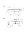
図1は、本発明の実施の形態に係るリクライニング椅子の概略斜視図であり、図2は、図1のリクライニング椅子からクッション部を取り外した概略斜視図である。
また図3は、図1のリクライニング椅子のクッション部の概略斜視図である。
図4は、図2のリクライニング椅子の概略側面図であり、図5は、図4においてX方向から見た部分拡大図である。The reclining
FIG. 1 is a schematic perspective view of a reclining chair according to an embodiment of the present invention, and FIG. 2 is a schematic perspective view in which a cushion portion is removed from the reclining chair of FIG.
FIG. 3 is a schematic perspective view of a cushion portion of the reclining chair of FIG.
4 is a schematic side view of the reclining chair of FIG. 2, and FIG. 5 is a partially enlarged view of FIG. 4 viewed from the X direction.
本発明の実施の形態に係るリクライニング椅子10は、図1〜図3に示すように、全体の骨組みを形作るためのリクライニング椅子フレーム11と、それに取り付けられたクッション部材12とから構成されている。 As shown in FIGS. 1 to 3, the reclining
リクライニング椅子フレーム11は、バックレストフレーム13と、座部フレーム14と、脚部を構成する前脚フレーム15及び後脚フレーム16とを備える。
そして腕部を乗せるためのアームレスト17と足部を乗せるためのレッグレストフレーム19と備えている。
またバックレストフレーム13と座部フレーム14とには、クッション部材12を取り付けた状態において、適宜な弾発力を与えるためのS字状ばね20(波ばね)とを備えている。The
An armrest 17 for placing the arm portion and a
Further, the
クッション部材12は、背当て部に相当する部分であるバックレストクッション部12aと座部に相当する部分である座部クッション部12bとよりなり、リクライニング椅子フレーム11に取り付けた状態から引き離すことにより取り外すことができる。
そして、バックレストクッション部12aの上部背面にはバックレストフレーム13の上部に被せる袋状部(図示しない)が形成されており、この袋状部をバックレストフレーム13の上部に被せることにより、バックレストクッション部12aがバックレストフレーム13に装着されるようになっている。
また座部クッション部12bは座部フレーム14の上に載置された状態となる。The
A bag-like portion (not shown) that covers the upper portion of the
Further, the
バックレストフレーム13は、図2に示すように、金属製のパイプを折り曲げて下方が開放するU字状に形成されており、複数(図2の例では2本)のS字状ばね20が取り付けられている。 As shown in FIG. 2, the
一方、座部フレーム14には、クッション部材12のうちバッグレストクッション部12aが取り付けられる。
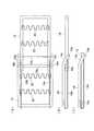
図7は、座部フレーム14を示し、図7(A)はその平面図で、図7(B)はその側面図である。
図に示すように、座部フレーム14は金属製のパイプを折り曲げて一方(図7において右側)が開放するU字状に形成されており、複数(図2,図7の例では2本)のS字状ばね20が取り付けられている。On the other hand, the bag
7 shows the
As shown in the figure, the
また、座部フレーム14の開放する側の両端部は下方に鈍角状に折り曲げられた湾曲部14cが形成されており、この鈍角状に折り曲げられた湾曲部14c端部には連結棒14aが設けられている。
(尚、連結棒14aは、座部フレーム14と一体化しておくことも当然可能である。)
さらに、座部フレーム14の対向する側部の内側にはそれぞれ案内ロッド14bが配置され、この案内ロッド14bの基端側はU字状に折り曲げられており、その端部が座部フレーム14の対向する側部の内側に挿入係止されている。
また、(図4に示すように、)座部フレーム14の対向する側部の略中間部の前側部位がピンP3によって前脚フレーム15の略中間部に枢支されている。Further, both ends of the
(Note that the connecting
Further, guide
In addition, as shown in FIG. 4, the front portion of the substantially intermediate portion of the opposite side portion of the
前脚フレーム15は、図1,図2に示すように、金属製のパイプを折り曲げて上方が開放するU字状に形成されており、床に接する部分にはプロテクター21が嵌め込まれている。
また、前脚フレーム15は、長さ方向の途中から前方に滑らかに屈曲している。As shown in FIGS. 1 and 2, the
The
後脚フレーム16も、図1,図2に示すように、前脚フレーム15と同様に、金属製のパイプを折り曲げて上方が開放するU字状に形成されており、床に接する部分にはプロテクター21が嵌め込まれている。
また、後脚フレーム16は、長さ方向の途中から後方に滑らかに屈曲している。
そのため、前脚フレーム15と後脚フレーム16の開脚時に、座部フレームの安定性が増す。As shown in FIGS. 1 and 2, the
Further, the
Therefore, the stability of the seat frame is increased when the
そして、図4に示すように、前脚フレーム15と後脚フレーム16との左右上端部は交差して交差部を形成しており、この交差部は後述する傾倒位置決め用のピンP1によって枢支されている。
この交差部においては、前脚フレーム15と後脚フレーム16とを、直接、ピンP1で枢着していてもよいし、一方の前脚フレーム15の上端に傾倒位置決め用のピンP1を取り付け、該上端から下がった位置の前脚フレーム15に後脚フレーム15を他方のピンで枢着することも可能である。
また一方の後脚フレーム16の上端に傾倒位置決め用のピンP1を取り付け、該上端から下がった位置の後脚フレーム16に前脚フレーム15を他方のピンで枢着することも可能である。
アームレスト17は、合成樹脂材によりできており内部が中空に一体成形されている。As shown in FIG. 4, the left and right upper ends of the
At this intersection, the
It is also possible to attach a tilting positioning pin P1 to the upper end of one
The
図6は、アームレストを示し、図6(A)はその係止部を含む断面図で、図6(B)はその底面図である。
このアームレスト17の後側はピンP2によりバックレストフレーム13に枢支され、これにより前側がピンP2を支点として、仮想線で示すように上方回動できるようになっている。
アームレストフレーム17の側部の各内面には、側面視で鋸刃状をなす複数個の係止突起17aが形成された係止部17bが設けられている。FIG. 6 shows an armrest, FIG. 6 (A) is a sectional view including the locking portion, and FIG. 6 (B) is a bottom view thereof.
The rear side of the
Each inner surface of the side portion of the
図6(A),図6(B)に示すように、係止突起17a間には前述したピンP1の両端部P1aが係止され、これによりバックレスト13の傾倒位置、すなわち傾倒角度が決定される。
このようにピンP1の両端部P1aが前後方向に移動され、係止突起17a間に係止されるとき、係止突起17aの先端部が鋸刃状に形成されているので、ピンP1の両端部P1aの移動及び係止が容易かつ確実に行うことができる。As shown in FIGS. 6 (A) and 6 (B), both end portions P1a of the pin P1 described above are locked between the locking
Thus, when the both ends P1a of the pin P1 are moved in the front-rear direction and locked between the locking
連結リンク18は、図4,図5に示すように、その上方にピンP4を備え、その下方にピンP5を備えている。
そして、図5に示すように、座部フレーム14の対向する側部の後端部位がピンP4によってバックレストフレーム13の下端近傍に枢支され、後脚フレーム16の略中間部よりやや下方の部位がピンP5によって連結リンク18に枢支されている。
レッグレストフレーム19は、レッグレスト部が取り付けられるところである。As shown in FIGS. 4 and 5, the connecting
As shown in FIG. 5, the rear end portion of the opposite side portion of the
The
図8は、レッグレストフレームを示し、図8(A)はその平面図で、図8(B)はその側面図で、図8(C)はその端面図である。
図8に示すように、金属製のパイプにより後端側が開放されてU字状に形成されており、複数(図8の例では2本)のS字状ばね20が取り付けられている。
また、レッグレストフレーム19の開放する側の両端部近傍には連結棒19aが設けられている。
そして、連結棒19aの両端部から突出する軸19bの先端にはそれぞれ当接部材19c(例えば、円形の当接部材)が取り付けられ、当接部材19cはレッグレストフレーム19の対向する側部の外側に位置している。FIG. 8 shows a legrest frame, FIG. 8 (A) is a plan view thereof, FIG. 8 (B) is a side view thereof, and FIG. 8 (C) is an end view thereof.
As shown in FIG. 8, the rear end side is opened by a metal pipe and is formed in a U shape, and a plurality (two in the example of FIG. 8) of S-shaped
In addition, connecting
Then, a
図7に示す座部フレーム14と図8に示すレッグレストフレーム19とは、案内ロッド14bを介して組み付けられている。 The
図9は、座部フレームとレッグレストフレームを組み付けた状態を示し、図9(A)はその平面図で、図9(B)はその側面図で、図9(C)は図9(A)及び図9(B)に示すレッグレストフレームが座部フレーム14に完全に押し込まれた状態を示す側面図である。 9 shows a state in which the seat frame and the legrest frame are assembled, FIG. 9A is a plan view thereof, FIG. 9B is a side view thereof, and FIG. 9C is FIG. ) And FIG. 9B are side views showing a state in which the legrest frame is completely pushed into the
図9(A)は、レッグレストフレーム19が座部フレーム14の前方に最大限引き出された状態を示す平面図であり、図9(B)はレッグレストフレーム19が座部フレーム14の前方に最大限引き出された状態を示す側面図である。
また、図9(C)はレッグレストフレーム19が座部フレーム14の下方に完全に押し込まれた状態を示す側面図である。9A is a plan view showing a state in which the
FIG. 9C is a side view showing a state in which the
レッグレストフレーム19は、座部フレーム14の連結棒14aにより下方から支持されるとともに、案内ロッド14bに案内されて座部フレーム14に対して前後方向に引き出され、あるいは押し込まれる。
なお、前述したように案内ロッド14bの一方端はU字状に屈曲されて座部フレーム14に挿入係止され、他方の端である自由端は中空状のレッグレストフレーム19の内部に挿入されている。The
As described above, one end of the
レッグレストフレーム19が座部フレーム14に対して前後方向に引き出され、あるいは押し込まれる際、レッグレストフレーム19の当接部材19cは座部フレーム14の下面に沿って移動する。 When the
そして、図9(A),図9(B)に示すように、レッグレストフレーム19が座部フレーム14の前方に最大限に引き出されると、当接部材19cは座部フレーム14の湾曲部14cの基端部(すなわち先に向かって)に滑らかに当接する。
すなわちレッグレストフレーム19は鈍角状の湾曲部14cにより徐々に停止していくので、強く引き出しても衝撃がない。As shown in FIGS. 9A and 9B, when the
That is, since the
そしてレッグレストフレーム19は円形の当接部材19cと連結棒14aにより片持ち状に支持される。
すなわち、レッグレストフレーム19が連結棒14aを支点として先端部が下がるのを当接部材19cが座部フレーム14に当たることにより防止している。
この状態でレッグレストフレーム19の先部に荷重を加えても、当接部材19cが座部フレーム14の下面に当たって支えるため、レッグレストフレーム19の先部はこれ以上下がらない。The
In other words, the
Even if a load is applied to the front portion of the
また、図9(C)に示すように、レッグレストフレーム19が座部フレーム14の下方に完全に押し込まれた状態のとき、レッグレストフレーム19の前端部は連結棒14aにより支持されるとともに、その後端部は案内ロッド14bの基端部側(後端側)に当接している。 Further, as shown in FIG. 9C, when the
さて、リクライニング椅子10は、次にように、全体を折り畳むことができる。
図10は、リクライニング椅子を折り畳んだ状態を説明する図であり、図10(A)はクッション部を載置する前の状態、図10(B)は図10(A)に示す折り畳み状態の上にクッション部を載置した状態を示す。Now, the reclining
10A and 10B are diagrams for explaining a state in which the reclining chair is folded. FIG. 10A is a state before the cushion portion is placed, and FIG. 10B is a top view of the folded state shown in FIG. Shows a state where the cushion portion is placed.
リクライニング椅子10のリクライニング椅子フレーム11は、バックレストフレーム13、レッグレストフレーム19を含む座部フレーム14、前脚フレーム15、後脚フレーム16、アームレスト17のそれぞれが、ピンP1〜P5のいずれかを介し、相互に枢動可能に枢支されているので、バックレストフレーム13と座部フレーム14とを合わせるように折り畳むと、図10(A)に示すように、リクライニング椅子フレーム11全体を折り畳むことができる。 The
さらに、図10(B)に示すように、図10(A)に示すリクライニング椅子フレーム11全体を折り畳んだ状態の上にクッション部材12を載置すると、リクライニング椅子10をコンパクトにまとめることができる。
この場合、図のように紐等を使うと保管に便利である。
このため、リクライニング椅子10は、持ち運びや設置等の取り扱いが容易となり、また、不使用時の保管に際しスペースを取らない。Furthermore, as shown in FIG. 10 (B), when the
In this case, using a string or the like as shown in the figure is convenient for storage.
For this reason, the reclining
(レッグレスト)
次に、本発明の主なる特徴点であるレッグレストフレーム19について説明する。
レッグレストフレーム19は前記座部フレーム14の前方から引き出し可能であることは既に述べた。
本発明の主なる特徴点は、レッグレストフレーム19に備わっているレッグレスト部Fが足部、詳しくは人の前脚を載せた場合、安定良く支持することができることである。
すなわち、レッグレスト部Fには、その先方に上面がなだらかな膨大部F1が設けられている。(Legrest)
Next, the
As described above, the
The main feature of the present invention is that the legrest portion F provided in the
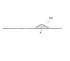
That is, the legrest part F is provided with a huge part F1 with a gentle upper surface at the tip.
図11は、レッグレスト部Fの構造を示す斜視図であり、図12は、レッグレスト部Fの構造を説明する断面図である。
レッグレストフレーム19には、フレーム自体やS字状バネ20を覆うための被覆シートfが取り付けられているが、これを利用してレッグレスト部Fが形成されている。
すなわち被覆シートfは前方に膨大部F1が設けられており、このような膨大部F1が設けられた被覆シートfをレッグレストフレーム19に取り付けることにより、レッグレスト部Fが出来上がる。FIG. 11 is a perspective view showing the structure of the legrest portion F, and FIG. 12 is a cross-sectional view illustrating the structure of the legrest portion F.
A covering sheet f for covering the frame itself and the S-shaped
That is, the covering sheet f is provided with an enormous portion F1 on the front, and the leg rest portion F is completed by attaching the covering sheet f provided with such an enlarging portion F1 to the
図13は、レッグレスト部Fをレッグレストフレーム19に取り付けた様態を説明する断面図である。
具体的には、被覆シートfの前端にはループ部が形成されており、レッグレストフレーム19の横フレームを巻き込むようにして、ループ部にS字状バネ20を挿入することにより、被覆シートfが取り付けられている。FIG. 13 is a cross-sectional view illustrating a state in which the legrest portion F is attached to the
Specifically, a loop portion is formed at the front end of the covering sheet f, and the covering sheet f is inserted by inserting an S-shaped
また被覆シートfの後端にも、ループ部が形成されており、このループ部に連結棒19aを挿入することにより取り付けられている。
被覆シートfの前方の膨大部F1は、被覆シートf空部に、クッション材、例えば、ポリウレタンチップが充填されることにより形成されている。
この膨大部F1の一部に図示しない充填口(ファスナーにより開閉自在)が設けられており、この充填口からポリウレタンチップの出し入れが可能である。
膨大部F1のクッション性を硬くするには、より多くポリウレタンチップ等の詰め物を充填すればよい。
被覆シートfの膨大部以外の部分にも少し詰め物を充填して肉厚にすると、接触性が柔らかくなる。Also, a loop portion is formed at the rear end of the covering sheet f, and is attached by inserting a connecting
The enormous portion F1 in front of the cover sheet f is formed by filling the empty space of the cover sheet f with a cushion material, for example, a polyurethane chip.
A filling port (not shown) that can be opened and closed by a fastener is provided in a part of the enormous portion F1, and the polyurethane chip can be taken in and out from the filling port.
In order to make the cushioning property of the enormous portion F1 harder, more padding such as polyurethane chips may be filled.
When a portion other than the enormous portion of the covering sheet f is filled with a little padding to increase the thickness, the contact property becomes soft.
図14は、肉厚にした被覆シートfを示す断面図である。
人の前脚を置く部分全体に詰め物を充填して厚みのある被覆シートfにしている。
ここで膨大部F1の形としては、断面でいうと、例えば半円形状、角が曲面の矩形状、三角形状、等が採用される。FIG. 14 is a cross-sectional view showing the cover sheet f having a large thickness.
The entire portion where the person's front leg is placed is filled with a filling to form a thick covering sheet f.
Here, as the shape of the enormous portion F1, in terms of a cross section, for example, a semicircular shape, a rectangular shape with a curved corner, a triangular shape, or the like is adopted.
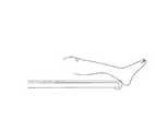
図15は、レッグレスト部Fを引き出して脚部を乗せた状態を示す概略図である。
この状態では、踵の上の部分が膨大部Fに当接するため、前脚が極めて安定した状態となる。
レッグレストフレーム19の横フレームの膨大部F1を不用意にいきなり足裏で押し込むようなことがあっても、座席フレーム14の湾曲部14cに当接部材19cが当接するため弾圧的な反力が作用し大した衝撃とならない。FIG. 15 is a schematic view showing a state in which the leg rest F is pulled out and the legs are put on.
In this state, since the upper part of the heel is in contact with the enormous part F, the front legs are in a very stable state.
Even if the enormous portion F1 of the lateral frame of the
参考までに、図16に、従来のような平たいレッグレスト部Fを略的に示す。
この状態では、下脚(踝から膝まで)とレッグレスト上面との間に空間が生じて足が安定しないのである。
踵の上の部分(足首の部分)がレッグレストフレーム19の横フレームに直接圧接するため、荷重が集中し圧迫を受けた痛みとなる。
本発明の実施の形態に係るリクライニング椅子10の利点を再度述べる。For reference, FIG. 16 schematically shows a conventional flat leg rest F.
In this state, a space is created between the lower leg (from the heel to the knee) and the upper surface of the legrest, and the foot is not stable.
Since the upper part of the heel (ankle part) is in direct contact with the lateral frame of the
The advantages of the
レッグレストフレーム19が座部フレーム14の前方から引き出し可能であるので、バックレストフレーム13の傾倒角度に関係なく、レッグレスト部分の長さ(奥行き)を着座者の体格や好みに応じて調整することができる。 Since the
また、前脚フレーム15と後脚フレーム16の開脚時に、座部フレーム14の前方端が後方端より高く傾斜しているので、着座者が安定して着座できる。
その上、座ったまま、レッグレストフレーム19を引っ込める場合、下方に引き込む動作となるため引っ込め易い。Further, when the
In addition, when the
また、前脚フレーム15は長さ方向の途中から前方に滑らかに屈曲し、後脚フレーム16は長さ方向の途中から後方に滑らかに屈曲しているので、着座時にリクライニング椅子10が安定する。
また、リクライニング椅子10が容易に折り畳まれるので、持ち運びや設置等の取り扱いが容易となり、また、不使用時の保管に際しスペースを取らない。
またレッグレスト部Fが先部に足載せ用の膨大部F1有しているので、レッグレストフレーム19の横フレームに足首が直接当たることはない。
また、膨大部F1上に踝の上付近が乗るので脚が安定性する。Further, since the
In addition, since the
Moreover, since the leg rest part F has the enormous part F1 for footrest at the front part, the ankle does not directly hit the lateral frame of the
Moreover, since the vicinity of the top of the heel is on the enormous portion F1, the legs are stable.
以上、本発明のリクライニング椅子の実施の形態について、説明したが、必ずしも実施の形態に限られるものではない。
例えば、図4と異なって、ピンP4及びピンP3を同じ高さ位置にしている例である。
図17は、そのリクライニング椅子の概略側面図であり、レッグレスト部Fを有するレッグレストフレーム19を引き出した状態を示す。
ピンP4及びピンP3とを同じ高さ位置にしているが、座る人の脚の先はやや上がり気味になる。
例えば、バックレストフレーム13を座部フレーム14に向け折り畳む構造であれば適用可能である。
またアームレスト17と前脚フレーム15及び後脚フレーム16の係止構造は、レールとネジを用いたものも当然採用可能である。
また前脚フレーム15及び後脚フレーム16は、途中から屈曲しているが、真っ直ぐになっていてもよい。As mentioned above, although embodiment of the reclining chair of this invention was described, it is not necessarily restricted to embodiment.
For example, unlike FIG. 4, the pin P4 and the pin P3 are the same height position.
FIG. 17 is a schematic side view of the reclining chair, showing a state in which the
Although the pin P4 and the pin P3 are at the same height position, the tip of the leg of the seated person is slightly raised.
For example, any structure that folds the
Further, as a locking structure of the armrest 17, the
The
本発明のリクライニング椅子は、座部フレームの前方から引き出し可能なレッグレストを設け、レッグレストフレーム19に備わったレッグレスト部F先部に足載せ用の膨大部F1を有しているものであり、レッグレストフレーム19の横フレームに、直接、足首が当たることはない。
また、膨大部F1の上に踝の上付近が乗るので脚が安定性する。
このことはリクライニング椅子以外の各椅子にも利用可能である。The reclining chair of the present invention is provided with a leg rest that can be pulled out from the front of the seat frame, and has a large portion F1 for footrest at the front end of the leg rest F provided on the
Moreover, since the vicinity of the top of the heel rides on the enormous portion F1, the legs are stable.
This is also applicable to each chair other than the reclining chair.
10…リクライニング椅子
11…リクライニング椅子フレーム
12…クッション部材
12a…バックレストクッション部
12b…座部クッション部
13…バックレストフレーム
14…座部フレーム
14a…連結棒
14b…案内ロッド
14c…湾曲部
15…前脚フレーム
16…後脚フレーム
17…アームレスト
17a…係止突起
17b…係止部
18…連結リンク
19…レッグレストフレーム
19a…連結棒
19b…軸
19c…当接部材
20…S字状ばね
21…プロテクター
P1〜P5…ピン
P1a…ピンP1の両端部
F…レッグレスト部
F1…膨大部DESCRIPTION OF
Claims (6)
Translated fromJapaneseレッグレストフレームと、
バックレストフレームと、
前記バックレストフレームの下端部に枢支される座部フレームと、
前脚フレームと後脚フレームの左右上方端部の交差部を枢支してなる脚部と、
後端側を前記バックレストフレームに枢支され前端側を上方に回動可能とし、かつ内部に前記交差部を所望の位置に係止可能とした係止部を有するアームレストフレームとを具備し、
前記座部フレームの開放する側の両端部は下方に鈍角状に折り曲げられた湾曲部が形成され、該湾曲部の端部には連結棒が設けられており、
前記レッグレストフレームが前記座部フレームの前方から引き出し可能であり、
該レッグレストフレームの開放する側の両端部近傍には連結棒が設けられ、連結棒の両端部から突出する先端には、それぞれ当接部材が取り付けられており、前記レッグレストフレームが引き出される際には、その当接部材が座席フレームの湾曲部に滑らかに当接して徐々に停止するものであり、
レッグレストフレームに備わったレッグレスト部が先部に足載せ用の膨大部を有していることを特徴とするリクライニング椅子。An armrest-operated reclining chair that includes a legrest and tilts and stands up by operating the armrest.
Legrest frame,
Backrest frame,
A seat frame pivotally supported by the lower end of the backrest frame;
A leg part pivotally supporting the intersection of the left and right upper ends of the front leg frame and the rear leg frame;
An armrest frame having a locking part pivotally supported by the backrest frame on the rear end side and capable of rotating the front end side upward, and capable of locking the intersecting part at a desired position.
Both ends on the opening side of the seat frame are formed with a bent portion bent obtusely downward, and a connecting rod is provided at the end of the bent portion,
The legrest frame can be pulled out from the front of the seat frame;
A connecting rod is provided in the vicinity of both ends on the opening side of the legrest frame, and a contact member is attached to each of the tips protruding from both ends of the connecting rod, and the legrest frame is pulled out. The contact member smoothly contacts the curved portion of the seat frame and gradually stops,
A reclining chair characterized in that a legrest part provided in a legrest frame has a huge part for footrest at a front part.
In the seat frame, the front portion of the substantially intermediate portion of the opposite side portion is pivotally supported by the pin P3 on the substantially intermediate portion of the front leg frame, and the rear end portion of the opposite side portion is supported by the pin P4. It is pivotally supported in the vicinity of the lower end of the frame, a portion slightly below the middle part of the rear leg frame is pivotally supported by the connecting link by the pin P5, and the reclining chair is folded around the pins P1 to P5 as the pivot. The recliner chair according to claim 1, wherein the recliner chair is a feature.
Priority Applications (1)
| Application Number | Priority Date | Filing Date | Title |
|---|---|---|---|
| JP2014240819AJP2016101301A (en) | 2014-11-28 | 2014-11-28 | Reclining chair |
Applications Claiming Priority (1)
| Application Number | Priority Date | Filing Date | Title |
|---|---|---|---|
| JP2014240819AJP2016101301A (en) | 2014-11-28 | 2014-11-28 | Reclining chair |
Publications (1)
| Publication Number | Publication Date |
|---|---|
| JP2016101301Atrue JP2016101301A (en) | 2016-06-02 |
Family
ID=56087843
Family Applications (1)
| Application Number | Title | Priority Date | Filing Date |
|---|---|---|---|
| JP2014240819APendingJP2016101301A (en) | 2014-11-28 | 2014-11-28 | Reclining chair |
Country Status (1)
| Country | Link |
|---|---|
| JP (1) | JP2016101301A (en) |
Cited By (2)
| Publication number | Priority date | Publication date | Assignee | Title |
|---|---|---|---|---|
| JP2018130316A (en)* | 2017-02-15 | 2018-08-23 | パラマウントベッド株式会社 | Body support device |
| CN110621198A (en)* | 2017-05-23 | 2019-12-27 | 野醍冷却器有限责任公司 | Portable chair and method of forming a portable chair |
Citations (3)
| Publication number | Priority date | Publication date | Assignee | Title |
|---|---|---|---|---|
| JP3182099B2 (en)* | 1996-10-31 | 2001-07-03 | 株式会社奥村組 | Removal method of shield excavator from arrival port |
| JP5255004B2 (en)* | 2010-01-28 | 2013-08-07 | アキテーヌジャパン株式会社 | Reclining chair |
| JP2014046160A (en)* | 2012-09-04 | 2014-03-17 | Masahiro Kamei | Reclining chair with ottoman |
- 2014
- 2014-11-28JPJP2014240819Apatent/JP2016101301A/enactivePending
Patent Citations (3)
| Publication number | Priority date | Publication date | Assignee | Title |
|---|---|---|---|---|
| JP3182099B2 (en)* | 1996-10-31 | 2001-07-03 | 株式会社奥村組 | Removal method of shield excavator from arrival port |
| JP5255004B2 (en)* | 2010-01-28 | 2013-08-07 | アキテーヌジャパン株式会社 | Reclining chair |
| JP2014046160A (en)* | 2012-09-04 | 2014-03-17 | Masahiro Kamei | Reclining chair with ottoman |
Cited By (5)
| Publication number | Priority date | Publication date | Assignee | Title |
|---|---|---|---|---|
| JP2018130316A (en)* | 2017-02-15 | 2018-08-23 | パラマウントベッド株式会社 | Body support device |
| CN110621198A (en)* | 2017-05-23 | 2019-12-27 | 野醍冷却器有限责任公司 | Portable chair and method of forming a portable chair |
| JP2020521535A (en)* | 2017-05-23 | 2020-07-27 | イエティ クーラーズ、エルエルシー | Portable chair and method of forming a portable chair |
| JP7216017B2 (en) | 2017-05-23 | 2023-01-31 | イエティ クーラーズ、エルエルシー | Portable chair and method of forming a portable chair |
| CN110621198B (en)* | 2017-05-23 | 2024-01-26 | 野醍冷却器有限责任公司 | Portable chair and method of forming a portable chair |
Similar Documents
| Publication | Publication Date | Title |
|---|---|---|
| CN104661568B (en) | Chair components with exterior coverings | |
| JP7411628B2 (en) | Push-up mechanism and chair | |
| US4555136A (en) | Furniture construction | |
| CN104540419A (en) | Chair | |
| JP5339548B2 (en) | Chair with backrest | |
| TW202023443A (en) | Folding chair | |
| JP5802090B2 (en) | Folding chair | |
| JP2016101301A (en) | Reclining chair | |
| JP5255004B2 (en) | Reclining chair | |
| TW201016170A (en) | Chair with tilting backrest | |
| CN111436783A (en) | A reclining lounge chair | |
| US20110156465A1 (en) | Dissembled chair with deployable stirrups | |
| JP5972432B2 (en) | Folding chair | |
| JP4183679B2 (en) | Reclining chair | |
| ITTO20100992A1 (en) | TRANSFORMABLE ARMCHAIR IN CHAISE LONGUE | |
| JP2014046160A (en) | Reclining chair with ottoman | |
| CN212213142U (en) | A reclining lounge chair | |
| US2704115A (en) | Folding contour chair constructions | |
| KR101673092B1 (en) | Chair that feet-prop is included | |
| JP5935320B2 (en) | Chair | |
| JP2004041400A (en) | Rocking chair | |
| KR20100034425A (en) | Chair | |
| KR20120063643A (en) | A chair with waist supports | |
| JP6168857B2 (en) | Chair massage machine | |
| JP3135449U (en) | Mechanism to lay the chair diagonally |
Legal Events
| Date | Code | Title | Description |
|---|---|---|---|
| A131 | Notification of reasons for refusal | Free format text:JAPANESE INTERMEDIATE CODE: A131 Effective date:20160825 | |
| A977 | Report on retrieval | Free format text:JAPANESE INTERMEDIATE CODE: A971007 Effective date:20160830 | |
| A02 | Decision of refusal | Free format text:JAPANESE INTERMEDIATE CODE: A02 Effective date:20170228 |