JP2016099627A - Method of controlling the flash time of external flash lamp - Google Patents
Method of controlling the flash time of external flash lampDownload PDFInfo
- Publication number
- JP2016099627A JP2016099627AJP2015224804AJP2015224804AJP2016099627AJP 2016099627 AJP2016099627 AJP 2016099627AJP 2015224804 AJP2015224804 AJP 2015224804AJP 2015224804 AJP2015224804 AJP 2015224804AJP 2016099627 AJP2016099627 AJP 2016099627A
- Authority
- JP
- Japan
- Prior art keywords
- flash
- time
- photosensitive member
- flashable
- row
- Prior art date
- Legal status (The legal status is an assumption and is not a legal conclusion. Google has not performed a legal analysis and makes no representation as to the accuracy of the status listed.)
- Pending
Links
Images


Classifications
- G—PHYSICS
- G03—PHOTOGRAPHY; CINEMATOGRAPHY; ANALOGOUS TECHNIQUES USING WAVES OTHER THAN OPTICAL WAVES; ELECTROGRAPHY; HOLOGRAPHY
- G03B—APPARATUS OR ARRANGEMENTS FOR TAKING PHOTOGRAPHS OR FOR PROJECTING OR VIEWING THEM; APPARATUS OR ARRANGEMENTS EMPLOYING ANALOGOUS TECHNIQUES USING WAVES OTHER THAN OPTICAL WAVES; ACCESSORIES THEREFOR
- G03B15/00—Special procedures for taking photographs; Apparatus therefor
- G03B15/02—Illuminating scene
- G03B15/03—Combinations of cameras with lighting apparatus; Flash units
- G03B15/04—Combinations of cameras with non-electronic flash apparatus; Non-electronic flash units
- G03B15/0452—Electrical ignition means connected to the shutter
- G03B15/0457—Ignition mechanisms for sequential ignition of flash lamps
- G—PHYSICS
- G01—MEASURING; TESTING
- G01J—MEASUREMENT OF INTENSITY, VELOCITY, SPECTRAL CONTENT, POLARISATION, PHASE OR PULSE CHARACTERISTICS OF INFRARED, VISIBLE OR ULTRAVIOLET LIGHT; COLORIMETRY; RADIATION PYROMETRY
- G01J1/00—Photometry, e.g. photographic exposure meter
- G01J1/10—Photometry, e.g. photographic exposure meter by comparison with reference light or electric value provisionally void
- G—PHYSICS
- G03—PHOTOGRAPHY; CINEMATOGRAPHY; ANALOGOUS TECHNIQUES USING WAVES OTHER THAN OPTICAL WAVES; ELECTROGRAPHY; HOLOGRAPHY
- G03B—APPARATUS OR ARRANGEMENTS FOR TAKING PHOTOGRAPHS OR FOR PROJECTING OR VIEWING THEM; APPARATUS OR ARRANGEMENTS EMPLOYING ANALOGOUS TECHNIQUES USING WAVES OTHER THAN OPTICAL WAVES; ACCESSORIES THEREFOR
- G03B2215/00—Special procedures for taking photographs; Apparatus therefor
- G03B2215/05—Combinations of cameras with electronic flash units
- G03B2215/0514—Separate unit
- G03B2215/0517—Housing
- G03B2215/0553—Housing with second integrated flash
Landscapes
- Physics & Mathematics (AREA)
- General Physics & Mathematics (AREA)
- Spectroscopy & Molecular Physics (AREA)
- Studio Devices (AREA)
- Stroboscope Apparatuses (AREA)
- Exposure Control For Cameras (AREA)
Abstract
Description
Translated fromJapanese本発明は、フラッシュランプの技術に関し、特に、携帯装置に用いられる外付けフラッシュランプの撮影方法に関する。 The present invention relates to flash lamp technology, and more particularly, to a method for photographing an external flash lamp used in a portable device.
デジタル撮影の画素および品質が進歩するにつれて、携帯装置(例えば携帯電話、タブレットコンピュータなど)に撮影機能が備え付けられることが趨勢となっている。しかしながら、これらの内蔵されたデジタルカメラは、低い光源または逆光の状況下においては、従来のデジタルカメラに匹敵するものではない。 As pixels and quality of digital photography advance, mobile devices (eg, mobile phones, tablet computers, etc.) are increasingly equipped with photography functions. However, these built-in digital cameras are not comparable to conventional digital cameras under low light source or backlight conditions.
内蔵されたデジタルカメラもLED(発光ダイオード)補助光ランプが設置されているが、携帯装置の電池容量およびLED放熱などの問題により、LED補助光ランプの補助光量が大きく制限される。携帯装置と被写体との距離が1メートルを超えた場合、LEDは、十分な光源を提供できず、感光部材が適度に露出させる。 The built-in digital camera also has an LED (light emitting diode) auxiliary light lamp, but the auxiliary light quantity of the LED auxiliary light lamp is greatly limited due to problems such as battery capacity of the portable device and LED heat dissipation. When the distance between the portable device and the subject exceeds 1 meter, the LED cannot provide a sufficient light source, and the photosensitive member is appropriately exposed.
キセノンフラッシュランプは、短時間内に大量の補助光源を提供することができるため、従来のデジタルカメラには、よくキセノンフラッシュランプが設置されている。キセノンフラッシュランプは、充電装置により、低電圧の電池電源を高圧電源に転換され、並びに大容量の高圧コンデンサに蓄蔵される。メカニカルシャッタに合わせて、適切な時間にキセノンフラッシュランプがトリガーリングされることによって、高圧コンデンサに蓄蔵された電気エネルギが、非常に短い時間で高輝度の補助光源に転換され、感光部材が低い光源または逆光の状況下で、適度に露出させる。キセノンフラッシュランプは、数十μFから数百μFで、三百から四百ボルトの電圧を耐えることができる高圧コンデンサが必要である。これらのコンデンサの体積は、非常に大きいため、携帯装置が軽薄短小の場合、負担可能な範囲ではない。よって、携帯装置の体積および重量を増加させない前提下で、外付けキセノンフラッシュランプは、実行可能で必要な選択肢となっている。 Since a xenon flash lamp can provide a large amount of auxiliary light source in a short time, a xenon flash lamp is often installed in a conventional digital camera. The xenon flash lamp is converted from a low-voltage battery power source to a high-voltage power source by a charging device and stored in a large-capacity high-voltage capacitor. When the xenon flash lamp is triggered at an appropriate time according to the mechanical shutter, the electrical energy stored in the high-voltage capacitor is converted into a high-intensity auxiliary light source in a very short time, and the photosensitive member is low. Proper exposure under light or backlight conditions. A xenon flash lamp requires a high voltage capacitor that can withstand a voltage of several hundred to four hundred volts by several tens of μF to several hundred μF. Since the volume of these capacitors is very large, when the portable device is light and thin, it is not in a range that can be borne. Therefore, the external xenon flash lamp is a viable and necessary option under the assumption that the volume and weight of the portable device are not increased.
高圧コンデンサの容量およびキセノンランプチューブの規格により、キセノンフラッシュランプの閃光時間は約数十ミリ秒から数百ミリ秒に至る。如何に正確な時点に閃光することにより、あらゆる感光部材が均等に露出させるかは、外付けキセノンフラッシュランプが実行可能であるか否かのもう一つの重要な課題である。一般的に携帯装置の備え付けられる撮影装置は、CMOS感光部材であり、並びにメカニカルシャッタは、備え付けられず、ローリングシャッタ(rolling shutter)が使用されている。図1に示すとおりである。図1は、先行技術のローリングシャッタを示している。図1をご参照ください。図1において、各線は、感光部材の各線の感光時間を示す。一つのフレーム(frame)内における各列感光部材の露出時間の長さは、同様であるが、各列の露出開始および終了時間は、すべて前の列と所定の遅延時間が隔たっている。この遅延時間内に撮影装置は、感光部材の情報を読み取り、並びにリセットを完成することによって、次のフレームの露出を進行する。撮影状況および撮影装置の設定が異なることによって、各列の露出時間は、約数ミリ秒から数百ミリ秒に至る。 Depending on the capacity of the high-pressure capacitor and the standard of the xenon lamp tube, the flash time of the xenon flash lamp ranges from several tens of milliseconds to several hundreds of milliseconds. How to expose all photosensitive members evenly by flashing at an accurate time is another important issue whether or not an external xenon flash lamp is feasible. In general, a photographing device provided in a portable device is a CMOS photosensitive member, and a mechanical shutter is not provided, and a rolling shutter is used. As shown in FIG. FIG. 1 shows a prior art rolling shutter. Please refer to Fig.1. In FIG. 1, each line indicates the exposure time of each line of the photosensitive member. The length of the exposure time of each row photosensitive member within one frame is the same, but the exposure start and end times of each row are all separated from the previous row by a predetermined delay time. Within this delay time, the photographing apparatus reads the information on the photosensitive member and completes the reset, thereby advancing the exposure of the next frame. Depending on the shooting conditions and the settings of the shooting device, the exposure time of each row ranges from about several milliseconds to several hundred milliseconds.
しかしながら、ローリングシャッタの制限により、外付けキセノンフラッシュランプは、しばしば最良の閃光時機を探し出すことができないため、撮影品質を高めることができない。 However, due to the limitations of the rolling shutter, external xenon flash lamps often cannot find the best flash timing and therefore cannot improve the shooting quality.
本発明の目的は、外付けフラッシュランプの閃光時間を制御する方法を提供することにある。 An object of the present invention is to provide a method for controlling the flash time of an external flash lamp.
外付けフラッシュランプの閃光時間を制御する方法は、携帯装置と外付けフラッシュランプとが組み合わせ、撮影の補光を行う時に用いられる。携帯装置は、N列の感光部材を有し、Nは自然数である。また、この方法は、特定事件を検測することを含む。この特定事件の発生時間は、第一列感光部材の露出開始時間が固定時間の長さであることに相対している。単一の閃光可能期間が存在するか否かを判断し、この期間内での閃光は、各列の感光部材により受け取ることができる。単一の閃光可能期間が存在するとき、特定事件の発生されたメッセージを外付けフラッシュランプに通知することによって、外付けフラッシュランプが特定事件から所定の遅延時間後、閃光指示がトリガーリングされる。よって、外付けフラッシュランプの閃光時間が単一の閃光可能期間内に入らせる。単一の閃光可能期間が存在しないとき、特定事件の発生されたメッセージを外付けフラッシュランプに通知することによって、外付けフラッシュランプが特定事件から所定の遅延時間後、閃光指示がトリガーリングされ、外付けフラッシュランプの第一回閃光時間が制御される。並びに、第一回閃光を行う後の所定の時間後に第二回閃光が行われる。 The method of controlling the flash time of the external flash lamp is used when a portable device and an external flash lamp are combined to perform supplementary light for photographing. The portable device has N rows of photosensitive members, where N is a natural number. The method also includes probing specific events. The occurrence time of this specific event is relative to the fact that the exposure start time of the first row photosensitive member is a fixed time. It is determined whether there is a single flashable period, and flash within this period can be received by each row of photosensitive members. When there is a single flashable period, the flash indication is triggered after a predetermined delay time from the specific event by notifying the external flash lamp of the message that occurred for the specific event. . Therefore, the flash time of the external flash lamp is set within a single flashable period. When there is no single flashable period, the flash indication is triggered after a predetermined delay time from the specific event by notifying the external flash lamp of the message that occurred in the specific event, The first flash time of the external flash lamp is controlled. In addition, the second flash is performed after a predetermined time after the first flash.
そのうち一つの好ましい態様において、単一の閃光可能期間が存在するか否かを判断するステップは、環境光の強度を検出することを含む。環境光の強度と予め設定した閾値とを比較する。環境光の強度が予め設定した閾値より低い場合、単一の閃光可能期間が存在すると判断する。逆に、環境光の強度が予め設定した閾値より高い場合は、単一の閃光可能期間が存在しないと判断する。 In one preferred embodiment, the step of determining whether there is a single flashable period includes detecting the intensity of ambient light. The ambient light intensity is compared with a preset threshold value. If the ambient light intensity is lower than a preset threshold value, it is determined that there is a single flashable period. Conversely, if the intensity of the ambient light is higher than a preset threshold value, it is determined that there is no single flashable period.
そのうち一つの好ましい態様において、当該方法は、異なるメーカに対応する携帯装置の予め設定した閾値を、外付けフラッシュランプの記憶装置に保存する、または、携帯装置が外付けフラッシュランプを制御するのに用いられるアプリケーションソフトウェアに設定することをさらに含む。 In one of the preferred embodiments, the method stores a preset threshold value of a portable device corresponding to a different manufacturer in an external flash lamp storage device, or the portable device controls the external flash lamp. It further includes setting to application software to be used.
そのうち一つの好ましい態様において、当該方法は、第二回閃光を行う後の所定の時間後に第三回閃光を行うステップをさらに含む。In one of the preferred embodiments, the method further includes performing a third flash after a predetermined time after performing the second flash.
そのうち一つの好ましい態様において、単一の閃光可能期間が存在するか否かのステップは、環境光の強度を検出することを含む。環境光の強度と予め設定した第一閾値および第二閾値とを比較する。そのうち、予め設定した第二閾値は、予め設定した第一閾値より大きい。環境光の強度が予め設定した第一閾値より小さい場合、閃光可能期間が存在すると判断する。環境光の強度が予め設定した第一閾値より大きく、かつ予め設定した第二閾値より小さい場合は、二回の閃光が行われる必要があると判断する。また、環境光の強度が予め設定した第二閾値より大きい場合は、三回またはさらに多数回の閃光が行われる必要があると判断する。 In one preferred embodiment, the step of determining whether there is a single flashable period includes detecting the intensity of ambient light. The ambient light intensity is compared with the first threshold value and the second threshold value set in advance. Among these, the preset second threshold value is larger than the preset first threshold value. If the ambient light intensity is smaller than the preset first threshold, it is determined that there is a flashable period. If the ambient light intensity is greater than a preset first threshold and less than a preset second threshold, it is determined that two flashes need to be performed. If the ambient light intensity is greater than a preset second threshold value, it is determined that three or more flashes need to be performed.
そのうち一つの好ましい態様において、当該方法は、異なるメーカに対応する携帯装置の予め設定した閾値を、外付けフラッシュランプの記憶装置に保存する、または、携帯装置が外付けフラッシュランプを制御するのに用いられるアプリケーションソフトウェアに設定することをさらに含む。 In one of the preferred embodiments, the method stores a preset threshold value of a portable device corresponding to a different manufacturer in an external flash lamp storage device, or the portable device controls the external flash lamp. It further includes setting to application software to be used.
そのうち一つの好ましい態様において、第一回閃光は、多くともP個目の感光部材列までカバーすることができる。また、第二回閃光は、多くともQ個目の感光部材の列までカバーすることができる。よって、P+Q<Nのとき、第二回閃光を行う後の所定の時間後に第三回閃光が行われる。そのうちP、Qは自然数である。 In one preferred embodiment, the first flash can cover at most the Pth photosensitive member array. Further, the second flash can cover at most the column of the Qth photosensitive member. Therefore, when P + Q <N, the third flash is performed after a predetermined time after the second flash is performed. Of these, P and Q are natural numbers.
そのうち一つの好ましい態様において、第一列感光部材は、第a列以前の感光部材と共同の閃光可能期間を有することができるが、第b列以後の感光部材と共同の閃光可能期間を有することができない。また、第N列感光部材は、第c列以後の感光部材と共同の閃光可能期間を有することができるが、第d列以前の感光部材と共同の閃光可能期間を有することができない。よって、第一回閃光は、第1列感光部材が露出を終了する時間の前に入る。並びに第X列感光部材の露出時間内に入り、かつ第二回閃光は、第N列感光部材が露出を開始する時間の後に入る。並びに第Y列感光部材の露出時間内に入る。そのうち、d≦X≦a、c≦Y≦bであり、a、b、c、d、X、Yは、自然数である。 In one of the preferred embodiments, the first row photosensitive member may have a flashable period jointed with the photosensitive member before the a-th row, but may have a flashable period jointed with the photosensitive member after the b-th row. I can't. The Nth row photosensitive member may have a flashable period jointed with the photosensitive members after the cth row, but cannot have a flashable period shared with the photosensitive members before the dth row. Therefore, the first flash comes before the time when the first row photosensitive member finishes exposure. In addition, the exposure time of the X-th row photosensitive member enters, and the second flash enters after the time when the N-th row photosensitive member starts exposure. In addition, the exposure time of the Yth row photosensitive member is entered. Among them, d ≦ X ≦ a and c ≦ Y ≦ b, and a, b, c, d, X, and Y are natural numbers.
そのうち一つの好ましい態様において、単一の閃光可能期間が存在するか否かを判断するステップは、テスト撮影プログラムを起動することを含む。テスト撮影プログラムにおいて、当時の環境光の強度によりフレームの露出が行われる。露出後のフレームを検査し、感光部材の輝度と参照閾値とを比較する。並びに参照閾値より輝度の低い感光部材があるか否かを判断する。参照閾値より輝度の低い感光部材がなければ、単一の閃光可能期間が存在すると判断する。参照閾値より輝度の低い感光部材があれば、単一の閃光可能期間が存在しないと判断する。In one preferred embodiment, the step of determining whether there is a single flashable period includes invoking a test imaging program. In the test shooting program, the frame is exposed according to the ambient light intensity at that time. The exposed frame is inspected, and the brightness of the photosensitive member is compared with a reference threshold value. In addition, it is determined whether there is a photosensitive member whose luminance is lower than the reference threshold. If there is no photosensitive member whose luminance is lower than the reference threshold, it is determined that there is a single flashable period. If there is a photosensitive member whose luminance is lower than the reference threshold, it is determined that there is no single flashable period.
そのうち一つの好ましい態様において、当該方法は、感光部材の輝度が参照閾値より高い列数(P)を検査し、並びに感光部材の総列数(N)と比較することによって、閃光回数を決定することをさらに含む。当該遅延時間は、フラッシュランプの遅延時間および特定事件から閃光可能期間までの時間によって決定される。 In one preferred embodiment, the method determines the number of flashes by examining the number of columns (P) where the brightness of the photosensitive member is greater than a reference threshold and comparing it to the total number of columns (N) of the photosensitive member. In addition. The delay time is determined by the delay time of the flash lamp and the time from the specific event to the flashable period.
また、本発明は、外付けフラッシュランプの閃光時間を制御する方法を提供した。当該方法は、携帯装置と外付けフラッシュランプとが組み合わせられたとき、撮影の補光を行うのに用いられる。携帯装置は、複数列の感光部材を有する。当該方法は、外付けフラッシュランプの第一回閃光時間を制御し、並びに第一回閃光を行う後の所定の時間後に第二回またはさらに多数回の閃光が行われることを含む。そのうち、あらゆる閃光回数を総合して、すべての感光部材を露出させることによって、感光部材がフラッシュランプの露出により取得された映像が組み合わせられ、一枚の写真が構成される。 The present invention also provides a method for controlling the flash time of an external flash lamp. This method is used for supplementing photographing when a portable device and an external flash lamp are combined. The portable device has a plurality of rows of photosensitive members. The method includes controlling the first flash time of the external flash lamp and performing a second or more flashes after a predetermined time after the first flash. Of these, all the flashes are combined and all the photosensitive members are exposed, so that the images obtained by the exposure of the flash lamps are combined with each other to compose one photo.
本発明の目的、技術内容、特徴および達成された効果についてさらに理解を深めるために、以下具体的な実施形態に対して詳細な説明を加える。 In order to further understand the objects, technical contents, features, and effects achieved by the present invention, detailed descriptions will be added to specific embodiments below.
(第一実施形態)
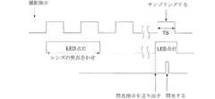
図2は、本発明の第一実施形態における閃光に適切な時間を示す図である。図2をご参照ください。閃光に適切な時間はたったt1およびt2の間に位置する。この時間内での閃光は、各列の感光部材により受信することができる。即ち、この閃光可能期間は、あらゆる感光部材の露出時間の重複区間である。もし閃光時間がt1より早ければ、後列における感光部材が露出することができない。もし閃光時間がt2より遅ければ、前列の感光部材が露出することができない。しかしながら、携帯装置は、通常マルチタスキング(multi−tasking)を実行するため、使用者がシャッタを押してからt1またはt2までの遅延時間は、決して固定ではない。そのため、先行技術では、外付けフラッシュランプの閃光時間がt1およびt2の間に安定的に制御される実行可能で信頼性の高い方法がなかったことで、外付けキセノンフラッシュランプの使用が深刻に制限されている。そこで、本発明は、図2に基づき、撮影方法を提示することによって、外付けフラッシュランプの閃光時間がt1およびt2の間に安定的に制御することができる。(First embodiment)
FIG. 2 is a diagram showing a time appropriate for flashing in the first embodiment of the present invention. Please refer to Figure 2. An appropriate time for the flash is only between t1 and t2. The flash within this time can be received by each row of photosensitive members. That is, the flashable period is an overlapping interval of exposure times of all photosensitive members. If the flash time is earlier than t1, the photosensitive members in the rear row cannot be exposed. If the flashing time is later than t2, the photosensitive members in the front row cannot be exposed. However, since the mobile device normally performs multi-tasking, the delay time from the user pressing the shutter to t1 or t2 is not fixed. Therefore, in the prior art, there was no feasible and reliable method in which the flash time of the external flash lamp was stably controlled between t1 and t2, so the use of the external xenon flash lamp became serious. Limited. Therefore, the present invention can stably control the flash time of the external flash lamp between t1 and t2 by presenting a photographing method based on FIG.
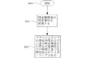
図3は、本実施形態の撮影方法を示す流れ図である。図3をご参照ください。撮影方法として携帯装置の外付けキセノンフラッシュランプを使用し、携帯装置が撮影時に、補光動作が進行される。この撮影方法は以下のステップを含む。 FIG. 3 is a flowchart showing the photographing method of the present embodiment. Please refer to FIG. As a photographing method, an external xenon flash lamp of a portable device is used, and a light supplement operation is performed when the portable device is photographing. This imaging method includes the following steps.
ステップS300:開始。 Step S300: Start.
ステップS301:閃光可能期間前の特定事件を検測する。図2をご参照ください。一般的に、携帯装置の使用されている画素取り込み装置は、上述のローリングシャッタ(rolling shutter)であるため、携帯装置内部の感光部材は、一つ一つ順次に露出する。また、携帯装置内部の各感光部材を露出する方法として積分方式が使用されているため、図2に示すように、閃光可能期間は、取り込まれた特定フレームの時間t1および時間t2の間に位置する。図2からわかるように、時間t1および時間t2は、最後列感光部材の露出開始(積分開始)時間から第一列感光部材の露出終了(積分終了)時間までを指す。もしこの時間内に閃光すれば、各掃引線は、すべて積分方式により感光が進行する。 Step S301: A specific event before the flashable period is measured. Please refer to Figure 2. Generally, a pixel capturing device used in a portable device is the above-described rolling shutter, so that the photosensitive members inside the portable device are sequentially exposed one by one. Further, since the integration method is used as a method of exposing each photosensitive member inside the portable device, the flashable period is located between time t1 and time t2 of the captured specific frame as shown in FIG. To do. As can be seen from FIG. 2, time t1 and time t2 indicate from the exposure start (integration start) time of the last row photosensitive member to the exposure end (integration end) time of the first row photosensitive member. If the flashing occurs within this time, each sweep line is exposed to light by an integral method.
携帯装置が、使用者によりシャッタ指示が押されたことが確認されたとき、測光、焦点合わせなどの準備作業が進行され、取り込もうとする特定フレームおよび感光部材の露出時間が決定される。このとき、外付けフラッシュ装置の閃光可能期間t1〜t2を知ることができる。たとえば、設計者は、特定のアプリケーションプログラムを設計することによって、特定フレームの時間を事前に推測し、または、その他のハードウェアの信号を利用することにより、特定フレームの時間を判定することができる。よって、本実施形態において特定事件の発生時間を取り入れ、事前に推測する基礎となる。この特定事件の発生時間は、上述の閃光可能期間に相対して固定した時間の長さである。即ち相対的に安定的で知ることが可能な時間である。閃光可能期間は、第1列感光部材の露出時間に相対して特定な関係を有するため、特定事件の発生する時間は、第1列感光部材の露出開始時間に相対して固定した時間の長さであると言える。 When it is confirmed that the user has pressed the shutter instruction by the user, the preparatory work such as photometry and focusing proceeds, and the exposure time of the specific frame to be captured and the photosensitive member is determined. At this time, the flashable periods t1 to t2 of the external flash device can be known. For example, the designer can determine the time of a specific frame by designing a specific application program in advance, or by using a signal of other hardware. . Therefore, in the present embodiment, the occurrence time of the specific incident is taken and becomes a basis for estimating in advance. The occurrence time of this specific event is the length of time fixed relative to the above flashable period. In other words, it is a relatively stable and knowable time. Since the flashable period has a specific relationship relative to the exposure time of the first row photosensitive member, the time at which the specific event occurs is the length of time fixed relative to the exposure start time of the first row photosensitive member. That's right.
携帯装置におけるアプリケーションプログラム(例えば携帯電話のアプリケーションプログラム)の実現方法を例にして説明すれば、携帯電話のアプリケーションプログラムは、上述した特定フレームの第一列感光部材が露出開始時間を取り込み、上述の特定事件にすることができる。このとき、固定時間の長さは、第一列感光部材の露出開始時間から最後列感光部材の露出開始時間までである。上述の特定事件は、上述の特定フレームの第K列感光部材の露出開始時間であってもよい。このとき、固定時間の長さは、第K例感光部材の露出開始時間から最後列感光部材の露出開始時間までである。また、上述の特定事件は、上述した特定フレームの前N個フレームの第K列感光部材の露出開始時間であってもよい。このとき、固定時間の長さは、N個フレームの時間に、第K列感光部材の露出開始時間から最後列感光部材の露出開始時間までを加えた時間の長さである。上述の特定事件は、特定フレームの前N個フレームの第K列感光部材の露出終了時間であってもよい。このとき、もし第K列感光部材の露出終了時間が最後列感光部材の露出開始時間より早ければ、上述の固定時間の長さは、N個フレームの時間に、第K列感光部材の露出終了時間から最後列感光部材の露出開始時間までの長さを加えた時間の長さである。もし第K列感光部材の露出終了時間が最後列感光部材の露出開始時間より遅ければ、上述の固定時間の長さは、N−1個フレーム時間に、第K列感光部材の露出終了時間から最後列感光部材の露出開始時間までの時間を加えた時間の長さである。以上は、閃光可能期間の最後の時点を「固定時間の長さ」の計算基礎としているが、時間t1および時間t2の間における任意の時点を「固定時間の長さ」の計算基礎としても同価である。 For example, a method for realizing an application program (for example, a mobile phone application program) in a mobile device will be described. The mobile phone application program captures the exposure start time by the first row photosensitive member of the specific frame described above. Can be a specific case. At this time, the length of the fixed time is from the exposure start time of the first row photosensitive member to the exposure start time of the last row photosensitive member. The specific event described above may be the exposure start time of the Kth row photosensitive member of the specific frame described above. At this time, the length of the fixed time is from the exposure start time of the Kth example photosensitive member to the exposure start time of the last row photosensitive member. Further, the specific event described above may be the exposure start time of the Kth row photosensitive member of N frames before the specific frame described above. At this time, the length of the fixed time is the length of time obtained by adding from the exposure start time of the Kth row photosensitive member to the exposure start time of the last row photosensitive member to the time of N frames. The specific event described above may be the exposure end time of the Kth row photosensitive member of the Nth frame before the specific frame. At this time, if the exposure end time of the Kth row photosensitive member is earlier than the exposure start time of the last row photosensitive member, the above-mentioned fixed time is equal to the Nth frame time. This is the length of time obtained by adding the length from the time to the exposure start time of the last row photosensitive member. If the exposure end time of the Kth row photosensitive member is later than the exposure start time of the last row photosensitive member, the length of the fixed time is N-1 frame time from the exposure end time of the Kth row photosensitive member. This is the length of time added to the exposure start time of the last row photosensitive member. In the above, the last time point of the flashable period is used as the basis for calculating the “fixed time length”, but any time point between time t1 and time t2 can be used as the basis for calculating the “fixed time length”. Value.
外付けハードウェアの角度から言えば、上述の特定事件は、携帯装置の内蔵された発光ダイオード補助光ランプの信号であってもよい。図4は、本実施形態における撮影方法に採用された携帯装置に内蔵された発光ダイオード補助光ランプの信号を表すオシログラムである。図4をご参照ください。携帯装置が撮影を行うとき、内蔵された発光ダイオード補助光ランプの第一回発光は、レンズが光線を集束していることを表す。内蔵された発光ダイオード補助光ランプの第二回発光は、画像取り込み(感光する)の動作が進行しはじめることを表す。よって、本発明のステップS301において、上述の特定事件は、発光ダイオード補助光ランプの第一回発光または発光ダイオード補助光ランプの第二回発光であってもよい。 In terms of the angle of external hardware, the specific event described above may be a signal of a light emitting diode auxiliary light lamp built in the portable device. FIG. 4 is an oscillogram representing a signal of a light emitting diode auxiliary light lamp built in the portable device employed in the photographing method according to the present embodiment. Please refer to FIG. When the portable device takes a picture, the first light emission of the built-in light emitting diode auxiliary light lamp indicates that the lens focuses the light beam. The second light emission of the built-in light emitting diode auxiliary light lamp indicates that the image capturing (photosensitive) operation starts to proceed. Therefore, in step S301 of the present invention, the specific event described above may be the first light emission of the light emitting diode auxiliary light lamp or the second light emission of the light emitting diode auxiliary light lamp.
ステップS302:フラッシュランプの遅延時間および上述の特定事件から閃光可能期間までの時間に基づき、閃光指示がトリガーリングされることによって、外付けフラッシュランプの閃光時間が閃光可能期間内に入らせる。フラッシュランプそのものは、トリガーリングされた閃光指示を受け取ってから実際に閃光するまで、遅延時間を有する。よって、上述の特定事件から閃光可能期間までの時間を考慮するほか、フラッシュランプそのものの遅延時間も考慮したほうがよい。簡単に言えば、上述の特定事件から閃光可能期間までの時間が固定値であり、フラッシュランプそのものの遅延時間も既知値であるため、これに基づいてどの時点に閃光指示がトリガーリングされるかを決定することができる。たとえば、トリガーリングされた閃光指示を受け取ってから実際に閃光するまでの遅延時間がtd(即ち、遅延時間tdの基準始点は閃光指示がトリガーリングされた時点である。)であれば、閃光指示がトリガーリングされる時間は、t1−tdからt2−tdの間にある。または、遅延時間tdの基準始点を上述の特定事件の時間から計算し、並びに上述の特定事件の発生時間がt0とすれば、閃光時間は、t1−t0<td<t2−t0という関係式を満たす必要があり、td終了後に直ちに外付けフラッシュ装置が閃光するよう、指示する。遅延時間tdの始点を計算するとき、上述の特定事件の時間と差異がある場合、その差異も考慮範囲に入れ、遅延時間tdの定義によって決定する必要がある。 Step S302: The flash instruction is triggered based on the delay time of the flash lamp and the time from the above-mentioned specific event to the flashable period, so that the flash time of the external flash lamp enters the flashable period. The flash lamp itself has a delay time from receiving the triggered flash instruction until it actually flashes. Therefore, it is better to consider the delay time of the flash lamp itself in addition to the time from the above-mentioned specific event to the flashable period. To put it simply, the time from the above-mentioned specific incident to the flashable period is a fixed value, and the delay time of the flash lamp itself is also a known value, so based on which point the flash instruction is triggered Can be determined. For example, if the delay time from the receipt of the triggered flash instruction to the actual flash is td (that is, the reference start point of the delay time td is the time when the flash instruction is triggered), the flash instruction. The time that is triggered is between t1-td and t2-td. Alternatively, if the reference start point of the delay time td is calculated from the time of the above-mentioned specific event and the occurrence time of the above-mentioned specific event is t0, the flashing time can be expressed by the relational expression t1-t0 <td <t2-t0. Instructs the external flash device to flash immediately after the end of td. When calculating the start point of the delay time td, if there is a difference from the time of the specific event described above, the difference needs to be taken into consideration and determined by the definition of the delay time td.
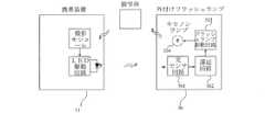
前述の外付けフラッシュランプは、ハードウェアにより接続され、携帯装置の備え付けられているユニバーサルシリアルバスポートまたはヘッドホンジャックにより電気的に結合され、携帯装置内部のソフトウェアにより特定事件が判断される。たとえば、感光開始時間または発光ダイオードにより信号が点灯されることによって、閃光技術が行われる。本発明の内容から、光結合の方法を実施形態として採用してもよい。図5は、本実施形態における撮影方法に採用された外付けフラッシュランプのシステム構成図である。図5をご参照ください。この外付けフラッシュランプ50が携帯装置と非電気的に接続される場合、外付けフラッシュランプ50は、光センサ回路501、遅延回路502、フラッシュランプ駆動回路503およびキセノンランプ504を含む。光センサ回路により携帯装置51における発光ダイオード補助光ランプの発光を検知し、上述の特定事件とする。よって、キセノンランプ504が閃光時間(t1〜t2)に閃光するよう、駆動される。 The external flash lamp described above is connected by hardware and is electrically coupled by a universal serial bus port or a headphone jack provided in the portable device, and a specific event is determined by software inside the portable device. For example, a flashing technique is performed by turning on a signal by a light exposure start time or a light emitting diode. From the content of the present invention, an optical coupling method may be adopted as an embodiment. FIG. 5 is a system configuration diagram of an external flash lamp employed in the photographing method according to the present embodiment. Please refer to FIG. When the
このほか、上述の実施形態においては、光結合の方法により実施しているが、本発明の技術領域から無線を採用してもよい。たとえばWIFI、近距離無線通信(Near Field Communication,NFC)またはブルートゥース(登録商標)の方法、携帯装置がシャッタ音を発する方法を結合して実施してもよい。故に、本発明はこれに限らない。 In addition, in the above-described embodiment, the optical coupling method is used, but wireless may be adopted from the technical field of the present invention. For example, a method of WIFI, near field communication (NFC) or Bluetooth (registered trademark), or a method in which a portable device emits a shutter sound may be combined. Therefore, the present invention is not limited to this.
さらに、一般的に言えば、上述のいくつかの特定事件の発生する時間は、上述の閃光可能期間に相対して固定した時間の長さである。即ち、相対的に安定的で知ることが可能な時間である。しかしながら、設計者は、上述のいくつかの事件に誤差がないことを保障することができない。よって、本発明は、上述のいくつかの特定事件の発生時間が上述の閃光可能期間の時間に相対して、誤差が許容可能な範囲より小さければ、(たとえば、閃光可能期間の二分の一以内である。)本発明の引き受け可能な範囲に属する。 Furthermore, generally speaking, the time of occurrence of some of the specific events described above is a fixed amount of time relative to the flashable period described above. That is, it is a relatively stable and knowable time. However, the designer cannot guarantee that there are no errors in some of the above cases. Thus, the present invention is not limited to the above-mentioned flashable period of time if the error is smaller than an acceptable range (for example, within one half of the flashable period). It belongs to the range that can be undertaken by the present invention.
図6および図2をご参照ください。図2に示す状況のように、一般的に閃光可能期間を探し出すことが可能である。閃光可能期間内での閃光は、各列の感光部材により受け取ることができる。しかしながら、環境光が比較的に強いまたは逆光撮影のような特殊状況下において、各列の感光部材の露出時間が短縮された場合、あらゆる感光部材の露出時間の重複区間を探し出すことができないかもしれない。図6に例示する状況のように、第1列感光部材が露出終了後に、第N−3列感光部材がやっと露出しはじめるため、第1列感光部材は、第N−3列以後の感光部材と共同の閃光可能期間を有することができない。(同様に、第2列感光部材は、第N−2列以後の感光部材と共同の閃光可能期間を有することができない。これによって類推することができる。) Please refer to Fig. 6 and Fig. 2. As in the situation shown in FIG. 2, it is generally possible to find a flashable period. The flash within the flashable period can be received by each row of photosensitive members. However, if the exposure time of the photosensitive members in each row is shortened under special circumstances such as relatively strong ambient light or backlighting, it may not be possible to find the overlapping sections of the exposure times of all photosensitive members. Absent. As the situation illustrated in FIG. 6, since the N-3th row photosensitive member finally begins to be exposed after the exposure of the first row photosensitive member, the first row photosensitive member is the photosensitive member after the N-3rd row. Can't have a joint flashable period with. (Similarly, the second row photosensitive member cannot have a flashable period jointly with the photosensitive members after the N-2nd row. This can be analogized.)
本発明に基づき、外付けフラッシュランプの閃光時間を制御する方法は、閃光可能期間が存在するか否かを判断することを含む。閃光可能期間内での閃光は、各列の感光部材により受け取ることができる。もしそうでなければ、二回またはさらに多数回の閃光が行われる。即ち、図6に示す状況下において、外付けフラッシュランプ50は、一回の閃光があらゆる感光部材により受け取ることができない状況を検出可能であるため、多数回の閃光が行われることができる。 In accordance with the present invention, a method for controlling the flash time of an external flash lamp includes determining whether a flashable period exists. The flash within the flashable period can be received by each row of photosensitive members. If not, two or more flashes are performed. That is, in the situation shown in FIG. 6, the
(第二実施形態)
図7をご参照ください。詳しく言えば、第二実施形態において、まず環境光の強度(ステップS701)が検出される。並びに、環境光の強度と予め設定した閾値とを比較(ステップS702)する。閃光の必要性を判断するため、いわゆる「環境光」は、撮影方向の環境光が比較的に良い。環境光の強度が予め設定した閾値より小さい場合、感光部材の露出時間が十分に長いことを表し、あらゆる感光部材の露出時間の重複区間を探し出すことができるため、一回の閃光のみで、あらゆる感光部材を露出(ステップS703)させる。逆に、環境光の強度が予め設定した閾値より大きい場合、感光部材の露出時間が、一回の閃光であらゆる感光部材が受け取ることができない程度に短縮されるため、第一回閃光を行う後の所定の時間後に第二回閃光(ステップS704)が行われる。(Second embodiment)
Please refer to FIG. Specifically, in the second embodiment, the intensity of ambient light (step S701) is first detected. In addition, the intensity of the ambient light is compared with a preset threshold value (step S702). In order to determine the necessity of flash, the so-called “ambient light” is relatively good in the photographing direction. If the ambient light intensity is smaller than the preset threshold, it means that the exposure time of the photosensitive member is sufficiently long, and it is possible to find the overlapping section of the exposure time of every photosensitive member. The photosensitive member is exposed (step S703). Conversely, if the ambient light intensity is greater than a preset threshold, the exposure time of the photosensitive member is shortened to the extent that any photosensitive member cannot be received with a single flash, so after the first flash is performed. The second flash (step S704) is performed after a predetermined time.
図6をご参照ください。第1列感光部材は、第N−4列(図示せず)以前の感光部材と共同の閃光可能期間を有することができるが、第N−3列以後の感光部材と共同の閃光可能期間を有することができない。また、第N列感光部材は、第5列(図示せず)以後の感光部材と共同の閃光可能期間を有することができるが、第4列以前の感光部材と共同の閃光可能期間を有することができない。よって、任意に二回の閃光を手配することができる。第一回閃光が第1列感光部材の露出終了時間の前に入らせ、並びに第X列感光部材の露出時間内に入るようにする。かつ第二回閃光が第N列感光部材の露出開始時間の後に入らせ、並びに第Y列感光部材の露出時間内に入るようにする。図6に例示するように、4≦X≦N−4、5≦Y≦N−3であり、即ち、第一回閃光は、必ず第1列感光部材の露出時間内(X≦N−4)に入り、かつ、第一回閃光は、必ず第N列感光部材が露出開始以前において最後に露出を終了する感光部材(4≦X)までカバーする必要がある。また、第二回閃光は、必ず第N列感光部材の露出時間内(5≦Y)に入り、かつ第二回閃光は、必ず第1列感光部材が露出終了後に最初に露出を開始する感光部材(Y≦N−3)までカバーする必要がある。 Please refer to FIG. The first row photosensitive member may have a flashable period jointed with a photosensitive member before the N-4th row (not shown), but may have a flashable period jointed with the photosensitive member after the N-3rd row. Cannot have. In addition, the Nth row photosensitive member may have a flashable period jointly with the photosensitive members after the fifth row (not shown), but has a flashable period jointly with the photosensitive members before the fourth row. I can't. Therefore, it is possible to arrange two flashes arbitrarily. The first flash is made to enter before the exposure end time of the first row photosensitive member, and to be within the exposure time of the X row photosensitive member. The second flash is made to enter after the exposure start time of the Nth row photosensitive member, and within the exposure time of the Yth row photosensitive member. As illustrated in FIG. 6, 4 ≦ X ≦ N−4 and 5 ≦ Y ≦ N−3, that is, the first flash is always within the exposure time of the first row photosensitive member (X ≦ N−4). ) And the first flash must always cover up to the photosensitive member (4 ≦ X) where exposure ends last before the exposure of the Nth row photosensitive member. In addition, the second flash always enters the exposure time (5 ≦ Y) of the Nth row photosensitive member, and the second flash always starts the exposure first after the exposure of the first row photosensitive member. It is necessary to cover up to the member (Y ≦ N−3).
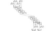
さらにひどい状況下で、二回の閃光もあらゆる感光部材により受け取ることができない場合は、三回またはさらに多数回の閃光を手配する必要がある。図8に例示した状況である。 In more severe situations, if two flashes cannot be received by any photosensitive member, it is necessary to arrange for three or more flashes. This is the situation illustrated in FIG.
(第三実施形態)
図9をご参照ください。この状況下において、第三実施形態では、まず環境光の強度を検出する(ステップS801)。並びに環境光の強度と予め設定した閾値とを比較する(ステップS802)。環境光の強度が予め設定した第一閾値より小さい場合、感光部材の露出時間が十分に長いことを表し、あらゆる感光部材の露出時間の重複区間を探し出すことができるため、一回の閃光のみで、あらゆる感光部材を露出することができる(ステップS803)。環境光の強度が予め設定した第一閾値より大きい場合は、続いて、環境光の強度が予め設定した第二閾値より大きいか否かを判断する(ステップS804)。環境光の強度が予め設定した第一閾値より大きく、かつ予め設定した第二閾値より小さい場合、二回の閃光であらゆる感光部材が受け取ることができるようにすることが十分であることを表す(ステップS805)。環境光の強度が予め設定した第二閾値より大きい場合、二回の閃光であらゆる感光部材が受け取ることができない状況を表し、三回の閃光を行う必要がある(ステップS806)。そのうち、予め設定した第二閾値は、予め設定した第一閾値より大きい。(Third embodiment)
Please refer to FIG. Under this situation, in the third embodiment, first, the intensity of ambient light is detected (step S801). In addition, the ambient light intensity is compared with a preset threshold value (step S802). If the intensity of the ambient light is smaller than the preset first threshold, it means that the exposure time of the photosensitive member is sufficiently long, and it is possible to search for overlapping sections of the exposure time of all photosensitive members, so only one flash is required. Any photosensitive member can be exposed (step S803). If the ambient light intensity is greater than a preset first threshold value, it is then determined whether the ambient light intensity is greater than a preset second threshold value (step S804). If the ambient light intensity is greater than a preset first threshold and less than a preset second threshold, it is sufficient to allow any photosensitive member to receive with two flashes ( Step S805). If the intensity of the ambient light is greater than the preset second threshold value, it represents a situation where any photosensitive member cannot be received with two flashes, and it is necessary to perform three flashes (step S806). Among these, the preset second threshold value is larger than the preset first threshold value.
明らかに、第四回またはさらに多数回の閃光が行われる必要がある場合は、それに対応する閾値を予め設定することができる。並びに上述の方法と類似した方法により判断を行うことができるため、ここでは詳細な説明を省略する。 Obviously, if a fourth or even more flashes need to be performed, a corresponding threshold can be preset. In addition, since the determination can be performed by a method similar to the above-described method, detailed description is omitted here.
二回またはさらに多数回の閃光が行われる場合、一部の感光部材列が重複して露出する可能性がある。たとえば、第一回の露出は、第1からj列までカバーし、第二回閃光は、第(j−n)から第K列までカバーする可能性がある。これは、本発明の達成しようとする機能を妨げない。また、二回またはさらに多数回の閃光が行われる場合、これらの閃光は、必ずしも同一フレームの露出時間内に行うとは限らない。たとえば、前の一つのフレームの露出時間内に第一回閃光を行うことによって、一部分の感光部材列をカバーし、別の一つのフレームの露出時間内に第一回閃光を行うことによって、他の部分の感光部材の列をカバーする。次いで、閃光を受け取った感光部材の取得された映像を組み合わせ、一枚の写真が構成される。 When two or more flashes are performed, a part of the photosensitive member rows may be exposed in an overlapping manner. For example, the first exposure may cover the first to jth rows and the second flash may cover the (jn) th to Kth rows. This does not interfere with the function to be achieved by the present invention. Further, when two or more flashes are performed, these flashes are not necessarily performed within the exposure time of the same frame. For example, by performing the first flash within the exposure time of one previous frame, covering a part of the photosensitive member row, and performing the first flash within the exposure time of another one frame, The row of photosensitive members in the portion is covered. Next, the captured images of the photosensitive members that have received the flash are combined to form a single photograph.
図6および図8をご参照ください。二回の閃光によって、あらゆる感光部材が十分に受け取ることができるか否かは、概念上、以下の角度から判断することができる。第一回閃光は、必ず第1列感光部材の露出終了時間前に入り、かつ第二回閃光は、必ず第N列感光部材の露出開始時間後に入る。第一回閃光が多くともP個目の感光部材列(即ち、第1列感光部材の露出終了時間前に、すでに露出を開始した最後の一列の感光部材が第P列である。)までカバーすることができ、かつ第二回閃光が多くともQ個目の感光部材列(即ち、第N列感光部材の露出開始時間後に、最初に露出を終了した感光部材が第N−Q−1列である。)までカバーすることができれば、P+Q<Nのとき、少なくとも第三回閃光が必要とする。図8に例示したように、P=4、Q=4(一般的に、あらゆる感光部材の露出時間が同じであれば、P=Qになる。)であるため、N>8のとき、二回の閃光は、あらゆる感光部材が受け取ることができないことで、少なくとも第三回閃光が必要とする。三回の閃光を超えるか否かを判断することも、類似した方法を応用することができる。即ち、第一回閃光が多くともP個目の感光部材列までカバーすることができ、第二回閃光が多くともQ個目の感光部材列までカバーすることができ、第三回閃光が多くともR個目の感光部材列までカバーすることができれば、P+Q+R<Nのとき、少なくとも第四回閃光が必要となる。 Refer to Fig. 6 and Fig. 8. Whether or not every photosensitive member can be sufficiently received by two flashes can be conceptually determined from the following angles. The first flash always comes before the exposure end time of the first row photosensitive member, and the second flash always comes after the exposure start time of the Nth row photosensitive member. The first flash is covered up to the Pth photosensitive member row (that is, the last photosensitive member already started exposure before the first row photosensitive member exposure time is the Pth row). And the second flash is at most the Qth photosensitive member row (that is, the photosensitive member that has been exposed first after the exposure start time of the Nth row photosensitive member is the N-Q-1th row). If P + Q <N, at least the third flash is required. As illustrated in FIG. 8, P = 4 and Q = 4 (generally, P = Q if exposure times of all photosensitive members are the same). Therefore, when N> 8, two The flash of one time cannot be received by any photosensitive member, so at least the third flash is required. A similar method can be applied to determine whether or not three flashes are exceeded. That is, the first flash can cover up to the Pth photosensitive member row, the second flash can cover up to the Qth photosensitive member row, and the third flash If it is possible to cover up to the Rth photosensitive member row, at least the fourth flash is required when P + Q + R <N.
感光部材は、環境光の変化に応じて、露出時間が変更される。これは、携帯装置内部におけるハードウェアおよび設定と関わりがあるため、異なるメーカの携帯装置によって、異なる変化量を有するかもしれない。しかしながら、基本的に、よい撮影効果を達成するために、携帯装置のメーカが異なるが、環境光の変化に応じて感光部材の露出時間が変更されることに対して、その変化量は大体同じである。よって、本発明において、外付けフラッシュランプ50は、携帯装置の外部アセンブリであるが、前述のように、環境光の強度と比較する予め設定した閾値(予め設定した第一または第二閾値)を事前に設定可能である。たとえば、予め設定した閾値を外付けフラッシュランプ50に保存する、または、移動装置が外付けフラッシュランプ50を制御するのに用いられるアプリケーションソフトウェアに設定することができる。 The exposure time of the photosensitive member is changed according to the change in ambient light. This is related to the hardware and settings inside the mobile device, so it may have different amounts of variation by mobile devices from different manufacturers. However, basically, in order to achieve a good shooting effect, the manufacturer of the portable device is different, but the exposure time of the photosensitive member is changed according to the change of the ambient light, but the change amount is almost the same. It is. Therefore, in the present invention, the
(第四実施形態)
第四実施形態において、異なるメーカの携帯装置に応じたより正確な効果を求めるために、外付けフラッシュランプ50は、携帯装置の関連情報を取得することができる。図10をご参照ください。たとえば、事前に異なるメーカの携帯装置に基づき、対応する閾値を予め設定し(予め設定した第一または第二閾値)、外付けフラッシュランプ50の記憶装置(記憶体505)に保存する。撮影しようとするとき、外付けフラッシュランプ50の処理回路506と携帯装置とが通信を行うことによって、携帯装置のメーカ型番または関連属性が取得される。並びに記憶装置に保存された予め設定した閾値(予め設定した第一または第二閾値)を参照することによって、二回またはさらに多数回の閃光が必要であるか否かを計算する。(Fourth embodiment)
In the fourth embodiment, the
前述の「環境光の強度と予め設定した閾値とを比較する」ことは、環境光の関連情報を取得する必要があることを表す。外付けフラッシュランプ50は、携帯装置によりこの情報を取得することができる。または、外付けフラッシュランプ50内部に環境光検出部材を設置することによって、環境光の関連情報を取得することができる。 The above-mentioned “comparing the intensity of ambient light with a preset threshold value” indicates that it is necessary to acquire related information of ambient light. The
(第五実施形態)
図11をご参照ください。第五実施形態において、一部のメーカ型番の携帯装置の対応する予め設定する閾値(予め設定する第一または第二閾値)が未知の場合、検測プログラムによって、適切な閃光回数を設定することができる。本実施形態において、例えば、携帯装置と外付けフラッシュランプとを組み合わせ、撮影しようとするとき、テスト撮影プログラムを起動する(ステップS901)。テスト撮影プログラムにおいて、携帯装置と外付けフラッシュランプとを組み合わせ、当時の環境光の強度に基づき、フレームの露出が行われる(ステップS902)。次いで、露出後のフレームを検査し、感光部材の輝度と参照閾値とを比較し(ステップS903)、並びに参照閾値より輝度の低い感光部材があるか否かを判断する(ステップS904)。もし参照閾値より輝度の低い感光部材がなければ、一回の閃光で十分である(ステップS905)。逆に、参考閾値より輝度の低い感光部材があれば、参照閾値より輝度の高い感光部材の列数(P)を検査し、並びに感光部材の総列数(N)と比較を行う(ステップS906、S907)。1<(N/P)<2の場合、閃光回数は2である。もし2<(N/P)<3の場合、閃光回数は3である。これによって類推する。このように、適切な閃光回数を探し出すことができる(ステップS908)。(Fifth embodiment)
Please refer to FIG. In the fifth embodiment, when the preset threshold value (the preset first or second threshold value) corresponding to the portable device of some manufacturer model number is unknown, an appropriate number of flashes is set by the inspection program. Can do. In the present embodiment, for example, when a portable device and an external flash lamp are combined for shooting, a test shooting program is started (step S901). In the test photographing program, the portable device and the external flash lamp are combined, and the frame is exposed based on the ambient light intensity at that time (step S902). Next, the exposed frame is inspected, the brightness of the photosensitive member is compared with the reference threshold value (step S903), and it is determined whether there is a photosensitive member whose brightness is lower than the reference threshold value (step S904). If there is no photosensitive member whose luminance is lower than the reference threshold, a single flash is sufficient (step S905). On the other hand, if there is a photosensitive member whose luminance is lower than the reference threshold, the number (P) of photosensitive members whose luminance is higher than the reference threshold is inspected and compared with the total number (N) of photosensitive members (step S906). , S907). When 1 <(N / P) <2, the number of flashes is 2. If 2 <(N / P) <3, the number of flashes is 3. By analogy with this. In this way, an appropriate number of flashes can be found (step S908).
上述のように、本発明は、特定事件を利用している。この特定事件の発生時間は、閃光可能時間に相対して安定的で知ることが可能である。かつフラッシュランプの遅延時間の制御と合わせ、フラッシュランプがトリガーリングされることによって、フラッシュランプを閃光するとき、閃光可能時間内に入らせる。このほか、一回の閃光で、あらゆる感光部材をカバーすることができない場合、多数回の閃光を行うことができる。よって、本発明の撮影方法により、感光部材が低い光源または逆光の状況下において適度に露出させることで、携帯装置の撮影品質を高める効果を果たす。 As described above, the present invention utilizes a specific case. The occurrence time of this specific event is stable and can be known relative to the flashable time. In combination with the control of the delay time of the flash lamp, the flash lamp is triggered so that the flash lamp enters the flashable time when flashing. In addition, when it is not possible to cover all the photosensitive members with a single flash, a large number of flashes can be performed. Therefore, the photographing method of the present invention has an effect of improving the photographing quality of the portable device by exposing the photosensitive member appropriately under a low light source or backlight condition.
もう一つの実施方法において、多数回の閃光における第一回閃光の発生時間は、前述の特定事件から計算して所定の遅延時間ではなく、外付けフラッシュランプまたは携帯装置が自ら決定された初期閃光時間である。初期閃光時間後、本発明に基づき、一回の撮影において、第二回または多数回の閃光をさらに行うことができる。たとえば、外付けフラッシュランプまたは携帯装置により初期閃光時間が自ら決定されるが、前述の判断方法により、一回の閃光があらゆる感光部材を十分に露出させない場合、同じ写真のために二回または多数回の閃光を行うことができる。また、一回の閃光であらゆる感光部材を十分に露出させることができるとしても、いつ閃光したらあらゆる感光部材を十分に露出させるかが確定しない場合も多数回の閃光を行ってもよい。 In another method of implementation, the first flash occurrence time in a large number of flashes is not a predetermined delay time calculated from the specific event described above, but an initial flash lamp or portable device determined by itself. It's time. After the initial flash time, according to the present invention, a second or multiple flashes can be further performed in one shooting. For example, if the initial flash time is determined by an external flash lamp or a portable device, but the above-mentioned judgment method does not sufficiently expose all the photosensitive members, one or two flashes for the same photograph. You can make one flash. Further, even if all the photosensitive members can be sufficiently exposed with a single flash, it is possible to perform a large number of flashes even when it is not certain when all the photosensitive members are sufficiently exposed when flashing.
本発明の好ましい実施形態における詳細な説明に記載された具体的な実施形態は、単なる本発明の技術内容を説明するのに用いられるだけで、本発明を上述の実施形態に制限することではない。本発明の思想、目的および特許請求の範囲内でのあらゆる変化の実施は、すべて本発明の特許請求の範囲に属する。たとえば、本発明の方法を実施するステップにおいて、必ずしも前後関係のステップではなく、順序を置換または並行して実施することができる。(たとえば、図9におけるステップS802およびS804は、順序を置換または並行して実施することができる。)よって、本発明の保護範囲は、特許請求の範囲を基準とする。 The specific embodiments described in the detailed description of the preferred embodiments of the present invention are merely used to describe the technical contents of the present invention, and do not limit the present invention to the above-described embodiments. . All changes that come within the spirit, purpose, and scope of the invention fall within the scope of the claims. For example, the steps of performing the method of the present invention are not necessarily contextual steps, and the order may be replaced or performed in parallel. (For example, steps S802 and S804 in FIG. 9 can be carried out in order or in parallel.) Therefore, the protection scope of the present invention is based on the claims.
S300〜S302:ステップ
S700〜S704:ステップ
S800〜S806:ステップ
S900〜S908:ステップ
50:外付けフラッシュランプ
501:光センサ回路
502:遅延回路
503:フラッシュランプ駆動回路
504:キセノンランプ
505:記憶体
506:処理回路
51:携帯装置S300 to S302: Steps S700 to S704: Steps S800 to S806: Steps S900 to S908: Steps
50: External flash lamp
501: Optical sensor circuit
502: Delay circuit
503: Flash lamp driving circuit
504: Xenon lamp
505: Memory
506: Processing circuit
51: Portable device
Claims (11)
Translated fromJapanese特定事件を検測し、前記特定事件の発生時間は、第1列感光部材の露出開始時間に相対して固定した時間の長さであるステップと、
単一の閃光可能期間が存在するか否かを判断かを判断し、単一の閃光可能期間内での閃光は、各列の感光部材により受け取り可能であるステップと、
単一の閃光可能期間が存在する場合、前記特定事件の発生情報を前記外付けフラッシュランプに通知することによって、前記外付けフラッシュランプが前記特定事件から所定の遅延時間後に、閃光指示がトリガーリングされることで、前記外付けフラッシュランプの閃光時間を単一の閃光可能期間内に入らせるステップと、
単一の閃光可能期間が存在しない場合、前記特定事件の発生情報を前記外付けフラッシュランプに通知することによって、前記外付けフラッシュランプが前記特定事件から所定の遅延時間後に、閃光指示がトリガーリングされ、前記外付けフラッシュランプの第一回閃光時間が制御され、並びに前記第一回閃光から所定の時間後に第二回閃光が行われるステップと、を含むことを特徴とする外付けフラッシュランプの閃光時間を制御する方法。When a portable device and an external flash lamp are combined, the method is used for supplementing photographing, wherein the portable device has N rows of photosensitive members, where N is a natural number,
Measuring a specific event, and the occurrence time of the specific event is a fixed length of time relative to the exposure start time of the first row photosensitive member; and
Determining whether there is a single flashable period, the flash within a single flashable period being receivable by each row of photosensitive members;
When there is a single flashable period, the flash indication is triggered after a predetermined delay time from the specific event by notifying the external flash lamp of the occurrence information of the specific event. A step of causing the flash time of the external flash lamp to fall within a single flashable period;
When a single flashable period does not exist, the flash indication is triggered after a predetermined delay time from the specific event by notifying the external flash lamp of the occurrence information of the specific event. The first flash time of the external flash lamp is controlled, and the second flash is performed after a predetermined time from the first flash. A method to control the flash duration.
環境光の強度を検測するステップと、
前記環境光の強度と予め設定した閾値とを比較するステップと、
前記環境光の強度が前記予め設定した閾値より小さい場合、単一の閃光可能期間が存在すると判断するステップと、
前記環境光の強度が前記予め設定した閾値より大きい場合は、単一の閃光可能期間が存在しないと判断するステップと、を含むことを特徴とする請求項1に記載の外付けフラッシュランプの閃光時間を制御する方法。Determining whether there is a single flashable period,
A step of measuring the intensity of ambient light;
Comparing the ambient light intensity with a preset threshold;
Determining that there is a single flashable period if the ambient light intensity is less than the preset threshold;
The flash of the external flash lamp according to claim 1, further comprising: determining that there is no single flashable period when the intensity of the ambient light is greater than the preset threshold value. How to control time.
環境光の強度を検測するステップと、
前記環境光の強度と予め設定した第一閾値または第二閾値とを比較し、前記予め設定した第二閾値は前記予め設定した第一閾値より大きいことと、
前記環境光の強度が前記予め設定した第一閾値より小さい場合、単一の閃光可能期間が存在すると判断するステップと、
前記環境光の強度が前記予め設定した第一閾値より大きく、かつ前記予め設定した第二閾値より小さい場合、二回の閃光が行われる必要があると判断するステップと、
前記環境光の強度が前記予め設定した第二閾値より大きい場合、三回または多数回の閃光が行われる必要があると判断するステップと、を含むことを特徴とする請求項1に記載の外付けフラッシュランプの閃光時間を制御する方法。The step of determining whether there is a single flashable period is:
A step of measuring the intensity of ambient light;
Comparing the ambient light intensity with a preset first threshold or second threshold, the preset second threshold being greater than the preset first threshold;
Determining that there is a single flashable period if the ambient light intensity is less than the preset first threshold;
If the ambient light intensity is greater than the preset first threshold and less than the preset second threshold, determining that two flashes need to be performed;
And determining that it is necessary to perform three or more flashes if the intensity of the ambient light is greater than the preset second threshold. A method of controlling the flashing time of the attached flash lamp.
第N列感光部材は、第c列以後の感光部材と共同の閃光可能期間を有することが可能であり、第d列以前の感光部材と共同の閃光可能期間を有しておらず、
前記第一回閃光は、第1列感光部材が露出を終了する前、かつ第X列感光部材の露出時間内に行い、
第二回閃光は、第N列感光部材が露出を開始する後、かつ第Y列感光部材の露出時間内に行い、d≦X≦a、c≦Y≦bであり、a、b、c、d、X、Yは自然数であることを特徴とする請求項1に記載の外付けフラッシュランプの閃光時間を制御する方法。The first row photosensitive member may have a flashable period jointed with the photosensitive member before the a-th row, and may not have a flashable period shared with the photosensitive member after the b-th row,
The N-th row photosensitive member may have a flashable period jointed with the photosensitive members after the c-th row, and may not have a flashable period shared with the photosensitive members before the d-th row,
The first flash is performed before the exposure of the first row photosensitive member and within the exposure time of the X row photosensitive member,
The second flash is performed after the exposure of the Nth row photosensitive member and within the exposure time of the Yth row photosensitive member, and d ≦ X ≦ a and c ≦ Y ≦ b, and a, b, c The method of claim 1, wherein d, X, and Y are natural numbers.
テスト撮影プログラムを起動し、テスト撮影プログラムにおいて、当時の環境光の強度に基づき、フレームの露出が行われるステップと、
露出後のフレームを検査し、感光部材の輝度と参照閾値とを比較し、並びに参照閾値より輝度の低い感光部材があるか否かを判断するステップと、
参照閾値より輝度の低い感光部材がない場合、単一の閃光可能期間が存在すると判断するステップと、
参照閾値より輝度の低い感光部材がある場合は、単一の閃光可能期間が存在しないと判断するステップと、を含むことを特徴とする請求項1に記載の外付けフラッシュランプの閃光時間を制御する方法。The step of determining whether there is a single flashable period is:
Start the test shooting program, and in the test shooting program, the frame is exposed based on the ambient light intensity at the time,
Inspecting the exposed frame, comparing the brightness of the photosensitive member to a reference threshold, and determining whether there is a photosensitive member having a brightness lower than the reference threshold;
Determining that there is a single flashable period if there is no photosensitive member having a brightness lower than the reference threshold;
The flash time of the external flash lamp according to claim 1, further comprising the step of determining that there is no single flashable period when there is a photosensitive member whose brightness is lower than a reference threshold value. how to.
前記携帯装置は、複数列の感光部材を有し、
前記外付けフラッシュランプの第一回閃光時間を制御し、並びに前記第一回閃光後の所定の時間後に第二回または多数回の閃光が行われ、前記すべての閃光回数を総合することにより、あらゆる感光部材を露出させることで、感光部材のフラッシュランプの露出により取得された映像が組み合わされ、一枚の写真を構成することを特徴とする外付けフラッシュランプの閃光時間を制御する方法。When a portable device and an external flash lamp are combined, a method used to supplement light for shooting,
The portable device has a plurality of rows of photosensitive members,
By controlling the first flash time of the external flash lamp, and a second or multiple flashes after a predetermined time after the first flash, and by combining all the flash times, A method for controlling the flashing time of an external flash lamp, comprising exposing all the photosensitive members to combine images acquired by exposure of the flash lamps of the photosensitive members to form a single photograph.
Applications Claiming Priority (6)
| Application Number | Priority Date | Filing Date | Title |
|---|---|---|---|
| TW103140180ATWI563845B (en) | 2014-11-19 | 2014-11-19 | Method for taking photo with extension flash module of mobile device |
| TW103140180 | 2014-11-19 | ||
| TW104107362 | 2015-03-09 | ||
| TW104107362ATWI584040B (en) | 2015-03-09 | 2015-03-09 | Method for controlling flash timing of extension flash module |
| TW104119387ATWI563846B (en) | 2015-06-16 | 2015-06-16 | Method for controlling flash timing of extension flash module |
| TW104119387 | 2015-06-16 |
Publications (1)
| Publication Number | Publication Date |
|---|---|
| JP2016099627Atrue JP2016099627A (en) | 2016-05-30 |
Family
ID=56077820
Family Applications (1)
| Application Number | Title | Priority Date | Filing Date |
|---|---|---|---|
| JP2015224804APendingJP2016099627A (en) | 2014-11-19 | 2015-11-17 | Method of controlling the flash time of external flash lamp |
Country Status (2)
| Country | Link |
|---|---|
| JP (1) | JP2016099627A (en) |
| KR (2) | KR20160059981A (en) |
Citations (2)
| Publication number | Priority date | Publication date | Assignee | Title |
|---|---|---|---|---|
| US20030007088A1 (en)* | 2001-06-01 | 2003-01-09 | Nokia Corporation | Control of a flash unit in a digital camera |
| JP2005106890A (en)* | 2003-09-29 | 2005-04-21 | Nec Corp | Flash unit for personal digital assistant device, flash control system and flash control method |
- 2015
- 2015-11-17JPJP2015224804Apatent/JP2016099627A/enactivePending
- 2015-11-18KRKR1020150161835Apatent/KR20160059981A/ennot_activeCeased
- 2016
- 2016-11-18KRKR1020160154121Apatent/KR20160135691A/ennot_activeWithdrawn
Patent Citations (2)
| Publication number | Priority date | Publication date | Assignee | Title |
|---|---|---|---|---|
| US20030007088A1 (en)* | 2001-06-01 | 2003-01-09 | Nokia Corporation | Control of a flash unit in a digital camera |
| JP2005106890A (en)* | 2003-09-29 | 2005-04-21 | Nec Corp | Flash unit for personal digital assistant device, flash control system and flash control method |
Also Published As
| Publication number | Publication date |
|---|---|
| KR20160135691A (en) | 2016-11-28 |
| KR20160059981A (en) | 2016-05-27 |
Similar Documents
| Publication | Publication Date | Title |
|---|---|---|
| JP2016099626A (en) | Method of controlling the flash time of external flash lamp | |
| US8150255B2 (en) | Flash control for electronic rolling shutter | |
| US9638791B2 (en) | Methods and apparatus for performing exposure estimation using a time-of-flight sensor | |
| US10025163B2 (en) | Flash unit and emitted light amount control method | |
| CN104580924A (en) | Flashlight power adjusting method and terminal | |
| US9706096B2 (en) | Method for taking photo with extension flash module of mobile device | |
| US9473692B2 (en) | Image processing apparatus, imaging apparatus, and determination method for controlling light emission | |
| US20070212053A1 (en) | Image recording apparatus, image recording method, and computer-readable recording medium | |
| US20180041676A1 (en) | Image pickup apparatus and control method | |
| KR20100104050A (en) | Method and apparatus for controlling flash emission | |
| JP2009150993A5 (en) | ||
| CN106303268A (en) | Method for controlling flash time of external flash lamp | |
| CN106878607A (en) | Method and electronic device for image generation based on electronic device | |
| US9389489B2 (en) | Photographing apparatus for recognizing type of external device, method of controlling the photographing apparatus, and the external device | |
| JP2016099627A (en) | Method of controlling the flash time of external flash lamp | |
| JP2017108336A (en) | Imaging device, control method thereof, and control program | |
| US9706130B2 (en) | Camera having HDR during pre-flash | |
| US20170118395A1 (en) | Auto-focus control in a camera to prevent oscillation | |
| JP2012063664A (en) | Photometric device and electronic camera | |
| CN104639841A (en) | Portable electronic device and camera shooting light supplement method | |
| TWI584040B (en) | Method for controlling flash timing of extension flash module | |
| KR101575628B1 (en) | A method for controlling the amount of flash light in a digital video signal processing apparatus | |
| TW201701646A (en) | Method for controlling flash timing of extension flash module | |
| JP2017097288A (en) | Imaging device, control method thereof, and control program | |
| US9876960B2 (en) | Image pickup apparatus that has two photometric means, control method therefor, and storage medium |
Legal Events
| Date | Code | Title | Description |
|---|---|---|---|
| A977 | Report on retrieval | Free format text:JAPANESE INTERMEDIATE CODE: A971007 Effective date:20170125 | |
| A131 | Notification of reasons for refusal | Free format text:JAPANESE INTERMEDIATE CODE: A131 Effective date:20170207 | |
| A02 | Decision of refusal | Free format text:JAPANESE INTERMEDIATE CODE: A02 Effective date:20170919 |