JP2016096846A - Hollow needle, equipment with needle, and medical equipment - Google Patents
Hollow needle, equipment with needle, and medical equipmentDownload PDFInfo
- Publication number
- JP2016096846A JP2016096846AJP2014233715AJP2014233715AJP2016096846AJP 2016096846 AJP2016096846 AJP 2016096846AJP 2014233715 AJP2014233715 AJP 2014233715AJP 2014233715 AJP2014233715 AJP 2014233715AJP 2016096846 AJP2016096846 AJP 2016096846A
- Authority
- JP
- Japan
- Prior art keywords
- needle
- hollow needle
- hollow
- tube
- tip
- Prior art date
- Legal status (The legal status is an assumption and is not a legal conclusion. Google has not performed a legal analysis and makes no representation as to the accuracy of the status listed.)
- Pending
Links
Images


Landscapes
- Infusion, Injection, And Reservoir Apparatuses (AREA)
Abstract
Translated fromJapaneseDescription
Translated fromJapanese本発明は、流体の注入や採取等を行う際に用いられる中空針、針付器具及び医療器具に関する。 The present invention relates to a hollow needle, an instrument with a needle, and a medical instrument that are used when fluid is injected or collected.
体内への薬液の注入や血液の採取等に用いられる中空の医療用針において、穿刺時の痛みを軽減すべく、針管の細径化や、穿刺抵抗を低減させるような刃面加工が施されている。また医療用針は、通常、金属材料で製造されるが、製造コストを低減すべく、金属材料に代えて、合成樹脂材料を用いて射出成形により一体的に形成された合成樹脂製針もある。合成樹脂製針において、金属製針と同等の穿刺性能を実現することは容易ではないが、種々の試みがなされている。 In hollow medical needles used for injecting medicinal solutions into the body and collecting blood, etc., the needle surface is reduced to reduce the diameter of the needle tube and reduce puncture resistance in order to reduce pain during puncture. ing. Medical needles are usually manufactured from a metal material, but there are also synthetic resin needles that are integrally formed by injection molding using a synthetic resin material instead of a metal material in order to reduce manufacturing costs. . In synthetic resin needles, it is not easy to achieve puncturing performance equivalent to that of metal needles, but various attempts have been made.
例えば、刃面の外縁部に角部を形成することで刃先を鋭利な形状とし、穿刺抵抗を低減した合成樹脂製針が提案されている(例えば特許文献1参照)。また刃面に錐体を形成することで、刃先を鋭利にするとともに、刃先部分の強度(剛性)を金属製針と同等程度まで向上させた合成樹脂製針も提案されている(例えば特許文献2参照)。 For example, a synthetic resin needle has been proposed in which corners are formed at the outer edge of the blade surface to make the blade edge sharp and the puncture resistance is reduced (see, for example, Patent Document 1). In addition, a synthetic resin needle has also been proposed in which a cone is formed on the blade surface to sharpen the blade edge, and the strength (rigidity) of the blade edge portion is improved to the same level as a metal needle (for example, Patent Documents). 2).
特許文献1に記載の合成樹脂製針のように、刃面の外縁部に角部を設け刃先を鋭利にすることで穿刺抵抗を低減させ、穿刺時の痛みを軽減することは可能であるが、刃先が外縁に設けられているので穿刺時に針管に対して加わる力が偏り、針管が撓んでしまう恐れがある。 Like the synthetic resin needle described in
特許文献2に記載の合成樹脂製針のように、刃面に錐体を設けることで刃先を鋭利にするとともに、刃先部分の強度を向上させることで穿刺抵抗を低減することも可能であるが、刃面に錐体を設けるための面積が必要となり、針管の細径化の妨げとなってしまう。 Like the synthetic resin needle described in
このように射出成形により製造される中空針において、針管を細径化しつつ、金属製の中空針と同等の穿刺性能を確保することは実現されていない。 Thus, in the hollow needle manufactured by injection molding, it is not realized that the puncture performance equivalent to that of a metal hollow needle is ensured while reducing the diameter of the needle tube.
本発明の目的は、十分な強度を有するとともに穿刺性能の高い中空針、針付器具及び医療器具を提供することである。 An object of the present invention is to provide a hollow needle, a needle-equipped device, and a medical device that have sufficient strength and high puncture performance.
本発明は、中空の針管の先端部に針先が形成され、前記針先の最先端部に刃先が形成された中空針であって、前記針先は、互いに交差することで前記刃先を形成する2つ以上の刃面と、流体の出入口となる2つ以上の流通口とを備え、それぞれの前記流通口は、互いに異なる前記刃面に設けられ、前記針管の中空部と連通するように形成されていることを特徴とする中空針である。 The present invention is a hollow needle in which a needle tip is formed at a distal end portion of a hollow needle tube, and a blade tip is formed at the most distal end portion of the needle tip, and the needle tips cross each other to form the blade tip Two or more blade surfaces and two or more flow ports serving as fluid inlets and outlets, each of the flow ports being provided on the blade surfaces different from each other, and communicating with the hollow portion of the needle tube It is a hollow needle characterized by being formed.
また本発明において、前記刃先は、前記針管の中心軸上に形成されていることを特徴とする。 In the present invention, the cutting edge is formed on a central axis of the needle tube.
また本発明において、前記刃面は、前記針管の中心軸に向かって凹むように湾曲して形成された曲面であることを特徴とする。 Further, in the present invention, the blade surface is a curved surface formed so as to be concave toward the central axis of the needle tube.
また本発明の中空針は、合成樹脂で形成されていることを特徴とする。 The hollow needle of the present invention is formed of a synthetic resin.
また本発明の中空針は、さらに被取付体に連結可能な針基を備え、前記針基は、前記針管に一体的に形成されていることを特徴とする。 The hollow needle of the present invention further includes a needle base that can be connected to an attached body, and the needle base is formed integrally with the needle tube.
また本発明は、前記中空針と筒体とを備え、前記中空針と前記筒体とが一体的に形成されていることを特徴とする針付器具である。 Moreover, this invention is the instrument with a needle | hook characterized by including the said hollow needle and a cylinder, and forming the said hollow needle and the said cylinder integrally.
また本発明は、前記中空針を備える医療器具である。 Moreover, this invention is a medical device provided with the said hollow needle.
本発明の中空針は、針先に互いに交差することで刃先を形成する2つ以上の刃面を備えていることで、刃先が針管の外縁よりも内側に形成される。これにより穿刺時に針先及び針管に加わる力の偏りが軽減され、針管の撓み等を抑制することができ、中空針の強度及び穿刺性能を向上させることができる。また本発明の中空針は、2つ以上の流通口を備えているので、万が一、一方の流通口が閉塞したとしても、流体の注出又は吸引を継続して行うことができる。さらに本発明の中空針は、形状が単純であり低コストで製造可能である。 The hollow needle of the present invention is provided with two or more blade surfaces that form the cutting edge by intersecting with each other at the needle tip, so that the cutting edge is formed inside the outer edge of the needle tube. Thereby, the bias of the force applied to the needle tip and the needle tube at the time of puncturing can be reduced, the bending of the needle tube can be suppressed, and the strength and puncture performance of the hollow needle can be improved. In addition, since the hollow needle of the present invention includes two or more flow ports, even if one of the flow ports is blocked, the fluid can be continuously poured out or sucked. Furthermore, the hollow needle of the present invention has a simple shape and can be manufactured at low cost.
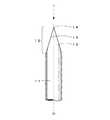
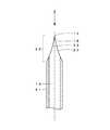
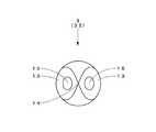
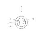
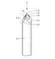
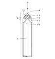
図1は、本発明の第1実施形態の中空針1の斜視図である。図2は、図1の中空針1の正面図である。図3は、図1の中空針1の側面図である。図4は、図1の中空針1の平面図である。図5は、図1の中空針1の底面図である。図6は、図2の中空針1の切断線A−Aの断面図である。図7(a)は、図6のB部の部分拡大図である。図7(b)、図7(c)は、図7(a)の中空針1の変形例を示す部分拡大図である。図8(a)は、図6のC部の部分拡大図である。図8(b)は、図8(a)の中空針1の変形例を示す部分拡大図である。 FIG. 1 is a perspective view of a
本実施形態の中空針1は、円筒体の針管11の先端部に針先12を有し、針先12の最先端部に刃先14を有する中空針であって、針先12が正面視において逆V字状となるように2つの刃面13が形成されており、針管11の中空部16と連通するように各刃面13に2つの流通口15が形成されている。 The
中空針1の用途は、特定の用途に限定されるものではなく、例えば、人又は動物の体内へ薬液を注入する際の注射針や、採血を行う際の採血針又は留置針の内針、薬液が充填された容器のゴム栓を穿刺するびん針、薬液混合用の吸引針、その他、物体に穿刺し流体の注出又は吸引を行う用途に幅広く用いることができる。また中空針1の材料は、特定の材料に限定されるものではなく、例えば、金属や合成樹脂、繊維状の充填材を含む合成樹脂等を用途に応じて選択することができる。 The use of the
針管11は、先端部に針先12を有する円筒管であり、針先12の最先端部に形成された鋭利な刃先14を突き当てて押し込むことで被穿刺物(図示省略)を穿刺し、中空部16から流通口15を介して流体の注出又は吸引を行う。針管11は、例えば、針基(図示省略)などに支持され、針基を介して薬液注入用のシリンジ(図示省略)や採血用の採血管ホルダ等に連結される。 The
針管11の長さ、外径及び内径の大きさは、用途によって適宜決めることができる。なお針管11は、外径が小さい程、穿刺した際に人体が痛みを感じる痛点を避けることができる。一例を挙げると、外径が0.18〜0.30mm、内径が0.07〜0.17mmのものが人体に穿刺する医療用針として特に好ましく用いられている。ただし、これに限定されるものではない。また針管11は、穿刺時に針管11にかかる力を分散すべく、外周面が先細のテーパ状に形成されていてもよい。さらに針管11は、薬液等の注入抵抗を低減すべく、内周面が先細のテーパ状に形成されていてもよい。 The length, the outer diameter, and the inner diameter of the
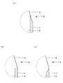
また針管11の中空部16の縁は、図7(a)に示すように刃面13と一体に外側に傾斜して形成されているが、これに限定されるものではなく、例えば、図7(b)に示すように水平に形成されていてもよく、図7(c)に示すように内側に傾斜して形成されていてもよい。 Further, the edge of the
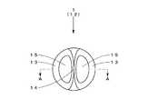
針先12は、半円球体に2つの刃面13が平面状に形成された形状をしており、2つの刃面13が交差して形成された刃先14と、針管11の中空部16と連通するように各刃面13に形成された2つの流通口15とを有する。 The
なお本実施形態において、針先12の天井面18は、図8(a)に示すように水平に形成されているが、これに限定されるものではなく、例えば、図8(b)に示すように上に凸の円弧状に形成されていてもよい。 In the present embodiment, the
2つの刃面13は、針先12が正面視(図2)において逆V字状になるように、針管11の中心軸Oを挟んで対称に、針管11の中心軸Oに対して傾斜するように平面状に形成されており、針管11の中心軸O上で互いに交差し、鋭利な刃先14を形成している。 The two
なお本実施形態において、2つの刃面13は、正面視における針管11の中心軸Oに対する刃先14と刃面13の基端とを結んだ直線の角度である刃先角度が同一となるように形成されているが、本発明の中空針において、各刃面における刃先角度は、特定の角度に限定されるものではなく、少なくとも刃先が針管の外縁よりも内側に形成されるように決められていればよい。 In this embodiment, the two
また本実施形態において、2つの刃面13は、刃面13を正面から見たときにリング状に形成されており、各刃面13の内周が流通口15の輪郭に一致しているが、これに限定されるものではなく、例えば、後述する第5実施形態の中空針5のように刃面53の内周と流通口55の輪郭とが必ずしも一致していなくてもよい。 In the present embodiment, the two
次に本実施形態の中空針1の作用について説明する。中空針1は、刃先14を被穿刺物に突き当てて押し込むことで穿刺される。また中空針1からの流体の注出又は吸引は、2つの流通口15を介して中空部16から行われる。 Next, the effect | action of the
本実施形態の中空針1では、針管11の中心軸O上に刃先14が形成されているので、穿刺時に針管11に加わる力の偏りが軽減され、針管11の撓み等を抑制することができ、強度及び穿刺性能を向上させることができる。これにより、例えば、樹脂製の中空針において、強度を確保しつつ細径化することが可能となる。また形状が単純なので低コストで製造可能である。 In the
さらに流通口15を2つ備えているので、万が一、一方が閉塞してしまった場合でも、流体の注出又は吸引を継続して行うことができる。このとき注出時又は吸引時の流体の抵抗の増大を防止すべく、1つの流通口15の面積が中空部16の断面積以上になるように流通口15が形成されていると、より好ましい。 Furthermore, since the two
図9は、本発明の第2実施形態の中空針2の軸方向に切断した断面図である。図1から図8に示す第1実施形態の中空針1と同一の構成には同一の符号を付して説明を省略する。第2実施形態の中空針2は、第1実施形態の中空針1と基本的構成は同じであるが、刃面23の形状が異なる。 FIG. 9 is a cross-sectional view of the
本実施形態の中空針2は、2つの刃面23が針管21の中心軸Oに向かって凹むように湾曲した曲面状に針先22に形成されている。なお針管21の胴部は、第1実施形態の中空針1の針管11の胴部と同一形状である。 The
このような刃面形状とすることで、中空針2の穿刺抵抗を低減させることができる。本発明の中空針において、刃面の形状は、特定の形状に限定されるものではなく、穿刺性能や製造コスト等を考慮し、適宜最適な形状を採用することができる。 By setting it as such a blade surface shape, the puncture resistance of the
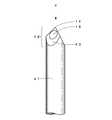
図10は、本発明の第3実施形態の中空針3の斜視図である。図11は、図10の中空針3の正面図である。図12は、図10の中空針3の側面図である。図13は、図10の中空針3の平面図である。図14は、図10の中空針3の底面図である。図1から図8に示す第1実施形態の中空針1と同一の構成には同一の符号を付して説明を省略する。第3実施形態の中空針3は、第1実施形態の中空針1と基本的構成は同じであるが、針先32の形状が異なる。 FIG. 10 is a perspective view of the
本実施形態の中空針3は、針先32の形状が半紡錘体に平面状の2つの刃面13が形成された形状になっている。このような針先形状とすることで、刃先14がより鋭利になるとともに、穿刺時に針管31に加わる力の偏りをより軽減させることができる。なお針管31の胴部は、第1実施形態の中空針1の針管11の胴部と同一形状である。 In the
本発明の中空針において、針先形状は、特定の形状に限定されるものではなく、穿刺性能や製造コスト等を考慮し、適宜最適な形状を採用することができる。 In the hollow needle of the present invention, the shape of the needle tip is not limited to a specific shape, and an optimum shape can be appropriately adopted in consideration of puncture performance, manufacturing cost, and the like.
図15は、本発明の第4実施形態の中空針4の斜視図である。図16は、図15の中空針4の正面図である。図17は、図10の中空針4の側面図である。図18は、図10の中空針4の平面図である。図19は、図10の中空針4の底面図である。図1から図8に示す第1実施形態の中空針1と同一の構成には同一の符号を付して説明を省略する。第4実施形態の中空針4は、第1実施形態の中空針1と基本的構成は同じであるが、刃面43の数が異なる。 FIG. 15 is a perspective view of the
本実施形態の中空針4は、針先42に刃面43が3つ形成されている。3つの刃面43は、刃先角度が同一であり、平面視(図18)において、120度の間隔で形成されている。3つの刃面43は、一点で交差しており、該一点において刃先14を形成している。また流通口15は、針管41の中空部16と連通するように各刃面43に形成されている。なお針管41の胴部は、第1実施形態の中空針1の針管11の胴部と同一形状である。 In the
本実施形態の中空針4のように、本発明の中空針において、刃面の数は、特定の数に限定されるものではなく、4つ以上であってもよい。また各刃面同士の間隔は、特定の角度に限定されるものではない。また本発明の中空針において、流通口は、少なくとも2つ以上形成されていればよく、刃面が3つ以上形成されている場合には流通口が形成されていない刃面があってもよい。 Like the
図20は、本発明の第5実施形態の中空針5の斜視図である。図1から図8に示す第1実施形態の中空針1と同一の構成には同一の符号を付して説明を省略する。第5実施形態の中空針5は、第1実施形態の中空針1と基本的構成は同じであるが、流通口55が針先52から針管51の胴部にかけて形成されている。 FIG. 20 is a perspective view of the
本実施形態の中空針5は、流通口55が正面視において長円形に形成されている。流通口55は、各刃面53から針管51の胴部にかけて針管51の中空部16に貫通するように形成されている。このように流通口55を形成することで流通口55の面積を大きくすることができる。 As for the
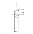
図21は、本発明の第6実施形態の中空針6の斜視図である。図1から図8に示す第1実施形態の中空針1と同一の構成には同一の符号を付して説明を省略する。第6実施形態の中空針6は、第1実施形態の中空針1に針基61が一体的に形成された中空針である。 FIG. 21 is a perspective view of the
中空針6は、針管11の基端部に一体的に形成された円筒キャップ様の針基61を備える。針基61は、例えば、注射器や採血管ホルダ等に連結可能な公知の針基と同様の構成、形状で形成することができる。 The
本実施形態の中空針6は、針管11と針基61とを射出成形等により一体的に形成することができるので、低コストで製造することができる。なお針基61は、針管11の基端部ではなく、針管11の途中から形成されていてもよい。 The
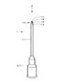
図22は、本発明の第7実施形態の針付器具7の斜視図である。図1から図8に示す第1実施形態の中空針1と同一の構成には同一の符号を付して説明を省略する。第7実施形態の針付器具7は、第1実施形態の中空針1にシリンジ71が一体的に形成された針付医療器具である。 FIG. 22 is a perspective view of the needle-equipped
本実施形態の針付器具7は、針管11の基端部に一体的に形成された円筒状のシリンジ71を備える。シリンジ71は、例えば、注射器等に用いられる公知のシリンジと同様の構成、形状で形成することができる。 The needled
本実施形態の針付器具7は、針管11とシリンジ71とを射出成形等により一体的に形成することができるので、低コストで製造することができる。なおシリンジ71は、針管11の基端部ではなく、針管11の途中から形成されていてもよい。また第6実施形態の中空針6の針基61からシリンジ71を一体的に形成してもよい。 The needled
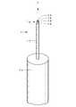
図23は、本発明の第8実施形態の針付器具8の軸方向に切断した断面図である。なお図23において、針先12の構成要素の符号は省略している。図1から図8に示す第1実施形態の中空針1と同一の構成には同一の符号を付して説明を省略する。第8実施形態の針付器具8は、中空針81と採血管ホルダ82とが一体的に形成された針付医療器具である。 FIG. 23 is a cross-sectional view of the needle-equipped
本実施形態の針付器具8では、中空針81の針管83の両端部に第1実施形態の中空針1と同一の針先12が形成されている。なお針管83の胴部は、第1実施形態の中空針1の針管11の胴部と同一形状である。 In the needle-equipped
採血管ホルダ82は、針管83の中間部分の外周面から一体的に形成されている。採血管ホルダ82は、採血時に用いられる公知の採血管ホルダであり、採血管を挿入可能に円筒状に形成されており、端部に持ち手となるフランジ85を備える。 The blood collection tube holder 82 is integrally formed from the outer peripheral surface of the intermediate portion of the needle tube 83. The blood collection tube holder 82 is a known blood collection tube holder used at the time of blood collection, is formed in a cylindrical shape so that a blood collection tube can be inserted, and includes a
なお採血管ホルダ82の内側に位置する針先12は、例えば、公知の採血管の栓を穿刺する用途に用いるものであり、人体に穿刺する用途に用いるものではないので、採血管ホルダ82の外側の針先12ほどの強度や穿刺性能が求められていない。このため採血管ホルダ82の内側の針先に要求される強度、穿刺性能、外径の大きさ等によっては、採血管ホルダ82の内側の針先は、他の公知のものを採用してもよい。 The
本実施形態の針付器具8は、中空針81と採血管ホルダ82とを射出成形等により一体的に形成することができるので、低コストで製造することができる。 The needled
以上、第1から第8実施形態の中空針1、2、3、4、5、6、針付器具7、8を用いて、本発明の中空針、針付器具及び医療器具を説明したが、本発明の中空針、針付器具及び医療器具は、上記実施形態に限定されるものではなく、要旨を変更しない範囲で変形して使用することができる。例えば、針管は、円筒体に限定されるものではなく、用途によっては角筒体等でもよい。 As described above, the hollow needle, the needle-equipped device, and the medical device of the present invention have been described using the
本発明の中空針、針付器具及び医療器具において、各実施形態の特徴を組合せたものを使用してもよいことは言うまでもない。例えば、第3から第6実施形態の中空針3、4、5、6においても、第2実施形態の中空針2のように、刃面が曲面状に形成されていてもよい。 Needless to say, the hollow needle, the needle-equipped device, and the medical device of the present invention may be a combination of the features of the embodiments. For example, in the
また針管は、流通口とは別に筒部に薬液注入や採血用の孔が設けられていてもよく、公知の硬膜外針のように先端部が曲がっていてもよい。さらに針管は、直管に限定されるものではなく、3方向以上に分岐していてもよい。 Further, the needle tube may be provided with a hole for injecting a drug solution or collecting blood in the cylinder part separately from the circulation port, and the tip part may be bent like a known epidural needle. Furthermore, the needle tube is not limited to a straight tube, and may be branched in three or more directions.
また本発明の中空針及び針付器具は、医療用途に限定されるものではなく、工業用途等、広く産業用途に用いることができる。さらに産業用途において、特に、細径な中空針及び針付器具として好適に用いることができる。 Further, the hollow needle and the instrument with a needle of the present invention are not limited to medical use, and can be widely used for industrial use such as industrial use. Furthermore, in industrial applications, it can be suitably used as a thin hollow needle and a needled instrument.
以上のとおり、図面を参照しながら好適な実施形態を説明したが、当業者であれば、本明細書を見て、自明な範囲内で種々の変更及び修正を容易に想定するであろう。従って、そのような変更及び修正は、請求の範囲から定まる発明の範囲内のものと解釈される。 As described above, the preferred embodiments have been described with reference to the drawings. However, those skilled in the art will readily understand various changes and modifications within the obvious scope by looking at the present specification. Therefore, such changes and modifications are interpreted as being within the scope of the invention defined by the claims.
1、2、3、4、5、6 中空針
7、8 針付器具
11、21、31、41、51、83 針管
12、22、32、42、52 針先
13、23、43、53 刃面
14 刃先
15、55 流通口
16 中空部
61 針基
71 シリンジ
82 採血管ホルダ1, 2, 3, 4, 5, 6
Claims (7)
Translated fromJapanese前記針先は、互いに交差することで前記刃先を形成する2つ以上の刃面と、流体の出入口となる2つ以上の流通口とを備え、
それぞれの前記流通口は、互いに異なる前記刃面に設けられ、前記針管の中空部と連通するように形成されていることを特徴とする中空針。A hollow needle in which a needle tip is formed at the tip of a hollow needle tube, and a blade tip is formed at the most distal end of the needle tip,
The needle tip includes two or more blade surfaces forming the blade edge by crossing each other, and two or more flow ports serving as a fluid inlet / outlet port,
Each said through-flow port is provided in the said mutually different blade surface, and is formed so that it may connect with the hollow part of the said needle tube, The hollow needle characterized by the above-mentioned.
前記針基は、前記針管に一体的に形成されていることを特徴とする請求項1から4のいずれか1項に記載の中空針。Furthermore, it has a needle base that can be connected to the mounted body,
The hollow needle according to any one of claims 1 to 4, wherein the needle base is formed integrally with the needle tube.
前記中空針と前記筒体とが一体的に形成されていることを特徴とする針付器具。A hollow needle according to any one of claims 1 to 5 and a cylindrical body,
The hollow needle and the cylindrical body are formed integrally with a needled instrument.
Priority Applications (1)
| Application Number | Priority Date | Filing Date | Title |
|---|---|---|---|
| JP2014233715AJP2016096846A (en) | 2014-11-18 | 2014-11-18 | Hollow needle, equipment with needle, and medical equipment |
Applications Claiming Priority (1)
| Application Number | Priority Date | Filing Date | Title |
|---|---|---|---|
| JP2014233715AJP2016096846A (en) | 2014-11-18 | 2014-11-18 | Hollow needle, equipment with needle, and medical equipment |
Publications (1)
| Publication Number | Publication Date |
|---|---|
| JP2016096846Atrue JP2016096846A (en) | 2016-05-30 |
Family
ID=56075242
Family Applications (1)
| Application Number | Title | Priority Date | Filing Date |
|---|---|---|---|
| JP2014233715APendingJP2016096846A (en) | 2014-11-18 | 2014-11-18 | Hollow needle, equipment with needle, and medical equipment |
Country Status (1)
| Country | Link |
|---|---|
| JP (1) | JP2016096846A (en) |
Cited By (4)
| Publication number | Priority date | Publication date | Assignee | Title |
|---|---|---|---|---|
| JP2020104440A (en)* | 2018-12-28 | 2020-07-09 | セイコーエプソン株式会社 | Printers and cartridges |
| JP2021527520A (en)* | 2018-06-18 | 2021-10-14 | ベクトン ディキンソン アンド カンパニー リミテッド | Vial adapter |
| WO2023132550A3 (en)* | 2022-01-04 | 2023-12-21 | 서석배 | Needle and needle tip comprising same |
| US12138434B2 (en) | 2018-03-19 | 2024-11-12 | Terumo Kabushiki Kaisha | Puncture needle and catheter assembly |
Citations (9)
| Publication number | Priority date | Publication date | Assignee | Title |
|---|---|---|---|---|
| JPS51119791U (en)* | 1975-03-26 | 1976-09-28 | ||
| JPS62194347U (en)* | 1986-05-30 | 1987-12-10 | ||
| JPH06327772A (en)* | 1993-03-23 | 1994-11-29 | Terumo Corp | Plastic cannula and its production |
| JPH08252925A (en)* | 1995-03-16 | 1996-10-01 | Matsushita Electric Ind Co Ltd | Liquid supply needle |
| JPH1119186A (en)* | 1997-07-07 | 1999-01-26 | Otsuka Pharmaceut Factory Inc | Plastic 2-hole double-ended needle |
| JP2001061944A (en)* | 1999-08-30 | 2001-03-13 | Showa Denko Kk | Transfer needle |
| JP2005525880A (en)* | 2002-05-16 | 2005-09-02 | スコット・ラボラトリーズ・インコーポレイテッド | Drug container insertion mechanism and method |
| US20090099535A1 (en)* | 2005-06-20 | 2009-04-16 | Yuean Wang | Disposable Needle for Syringes and Infusions and the Manufacture Thereof |
| JP2011167230A (en)* | 2010-02-16 | 2011-09-01 | Terumo Corp | Mixing implement |
- 2014
- 2014-11-18JPJP2014233715Apatent/JP2016096846A/enactivePending
Patent Citations (9)
| Publication number | Priority date | Publication date | Assignee | Title |
|---|---|---|---|---|
| JPS51119791U (en)* | 1975-03-26 | 1976-09-28 | ||
| JPS62194347U (en)* | 1986-05-30 | 1987-12-10 | ||
| JPH06327772A (en)* | 1993-03-23 | 1994-11-29 | Terumo Corp | Plastic cannula and its production |
| JPH08252925A (en)* | 1995-03-16 | 1996-10-01 | Matsushita Electric Ind Co Ltd | Liquid supply needle |
| JPH1119186A (en)* | 1997-07-07 | 1999-01-26 | Otsuka Pharmaceut Factory Inc | Plastic 2-hole double-ended needle |
| JP2001061944A (en)* | 1999-08-30 | 2001-03-13 | Showa Denko Kk | Transfer needle |
| JP2005525880A (en)* | 2002-05-16 | 2005-09-02 | スコット・ラボラトリーズ・インコーポレイテッド | Drug container insertion mechanism and method |
| US20090099535A1 (en)* | 2005-06-20 | 2009-04-16 | Yuean Wang | Disposable Needle for Syringes and Infusions and the Manufacture Thereof |
| JP2011167230A (en)* | 2010-02-16 | 2011-09-01 | Terumo Corp | Mixing implement |
Cited By (8)
| Publication number | Priority date | Publication date | Assignee | Title |
|---|---|---|---|---|
| US12138434B2 (en) | 2018-03-19 | 2024-11-12 | Terumo Kabushiki Kaisha | Puncture needle and catheter assembly |
| JP2021527520A (en)* | 2018-06-18 | 2021-10-14 | ベクトン ディキンソン アンド カンパニー リミテッド | Vial adapter |
| JP7303220B2 (en) | 2018-06-18 | 2023-07-04 | ベクトン ディキンソン アンド カンパニー リミテッド | vial adapter |
| JP2023120377A (en)* | 2018-06-18 | 2023-08-29 | ベクトン ディキンソン アンド カンパニー リミテッド | vial adapter |
| US11986440B2 (en) | 2018-06-18 | 2024-05-21 | Becton Dickinson and Company Limited | Piercing member for vial adapter |
| JP7524417B2 (en) | 2018-06-18 | 2024-07-29 | ベクトン ディキンソン アンド カンパニー リミテッド | Vial Adapter |
| JP2020104440A (en)* | 2018-12-28 | 2020-07-09 | セイコーエプソン株式会社 | Printers and cartridges |
| WO2023132550A3 (en)* | 2022-01-04 | 2023-12-21 | 서석배 | Needle and needle tip comprising same |
Similar Documents
| Publication | Publication Date | Title |
|---|---|---|
| JP5250919B2 (en) | Needle tip | |
| JP2016096846A (en) | Hollow needle, equipment with needle, and medical equipment | |
| KR20030037261A (en) | Medical bevel needle | |
| JP2023076687A (en) | 5-beveled cannula for blood collection device | |
| JP6861621B2 (en) | Pen needle assembly | |
| WO2011122350A1 (en) | Puncture needle and puncture tool | |
| JP5437510B1 (en) | Two-chamber syringe | |
| CA2800539C (en) | Port device | |
| AU2011252213A1 (en) | Port device | |
| JP6873976B2 (en) | Discharger with improved perforated tip | |
| JP2016059427A (en) | Hollow needle, appliance with needle, and medical appliance | |
| JP2002165881A (en) | Synthetic resin needle | |
| US8911405B2 (en) | Needle device | |
| JP6198694B2 (en) | Needle | |
| CN106039463A (en) | Injection needle, injection needle unit and fluid injection device | |
| US8382714B2 (en) | Rail-guided epidural-spinal needle | |
| JP6524392B2 (en) | Syringe with injection needle | |
| JP2018078978A (en) | Synthetic resin injection needle | |
| JP6343399B2 (en) | Medical liquid applicator | |
| CN204890809U (en) | Medical treatment is with needle and supporting components of medical treatment with needle | |
| CN221490103U (en) | Oblique needle tip and bone opening device | |
| RU57601U1 (en) | DEVICE FOR DUTYING AND ADMINISTRATION OF MEDICINES IN THE HOLLOW BODY BODY | |
| CN209826798U (en) | Biopsy needle | |
| JP2021106715A (en) | Injection needle and method for using injection needle | |
| CN208405588U (en) | Syringe needle for transfusion device |
Legal Events
| Date | Code | Title | Description |
|---|---|---|---|
| A621 | Written request for application examination | Free format text:JAPANESE INTERMEDIATE CODE: A621 Effective date:20171113 | |
| A131 | Notification of reasons for refusal | Free format text:JAPANESE INTERMEDIATE CODE: A131 Effective date:20180711 | |
| A977 | Report on retrieval | Free format text:JAPANESE INTERMEDIATE CODE: A971007 Effective date:20180713 | |
| A02 | Decision of refusal | Free format text:JAPANESE INTERMEDIATE CODE: A02 Effective date:20190125 |