JP2016096249A - Shield cover and electronic device - Google Patents
Shield cover and electronic deviceDownload PDFInfo
- Publication number
- JP2016096249A JP2016096249AJP2014231644AJP2014231644AJP2016096249AJP 2016096249 AJP2016096249 AJP 2016096249AJP 2014231644 AJP2014231644 AJP 2014231644AJP 2014231644 AJP2014231644 AJP 2014231644AJP 2016096249 AJP2016096249 AJP 2016096249A
- Authority
- JP
- Japan
- Prior art keywords
- shield cover
- semiconductor element
- bonding member
- thermal bonding
- metal plate
- Prior art date
- Legal status (The legal status is an assumption and is not a legal conclusion. Google has not performed a legal analysis and makes no representation as to the accuracy of the status listed.)
- Pending
Links
Images


Landscapes
- Shielding Devices Or Components To Electric Or Magnetic Fields (AREA)
- Cooling Or The Like Of Electrical Apparatus (AREA)
- Cooling Or The Like Of Semiconductors Or Solid State Devices (AREA)
- Devices For Indicating Variable Information By Combining Individual Elements (AREA)
Abstract
Description
Translated fromJapanese本発明は、シールドカバー及び電子装置に関するものである。 The present invention relates to a shield cover and an electronic device.
近年、スマートフォンやタブレット等の表示画面を有する携帯端末となる電子装置が普及しており、これらのスマートフォンやタブレット等は、携帯性の観点から、軽量化の他、薄型化が求められている。ところで、スマートフォンやタブレット等においては、CPU(Central Processing Unit)、パワーマネージメントチップ、無線通信チップ等の半導体素子が搭載されているが、これらの半導体素子は、動作させると熱が発生する。このように半導体素子において熱が発生し高温になると、半導体素子における機能が低下するため、半導体素子を冷却することが必須となる。 In recent years, electronic devices serving as mobile terminals having display screens such as smartphones and tablets have become widespread, and these smartphones, tablets, and the like are required to be lighter and thinner in terms of portability. By the way, in smart phones, tablets, and the like, semiconductor elements such as a CPU (Central Processing Unit), a power management chip, and a wireless communication chip are mounted. When these semiconductor elements are operated, heat is generated. As described above, when heat is generated in the semiconductor element and the temperature is increased, the function of the semiconductor element is deteriorated, so that the semiconductor element must be cooled.
半導体素子を冷却する方法としては、冷却ファン等の可動部品により放熱するアクティブ機構の他、可動部品を用いることなく放熱板等により放熱を行うパッシブ機構がある。スマートフォンやタブレット等においては、携帯性の観点より軽量化や薄型化が求められていることから、パッシブ機構が好ましいとされている。パッシブ機構では、半導体素子において発生した熱が、半導体素子と放熱板等との間に形成された熱伝導部材を介して、放熱板等に熱伝導され、放熱板等において放熱されることにより、半導体素子が冷却される。 As a method of cooling the semiconductor element, there is an active mechanism that radiates heat using a movable part such as a cooling fan, and a passive mechanism that radiates heat using a heat radiating plate or the like without using a movable part. In smart phones, tablets, and the like, passive mechanisms are preferred because they are required to be lightweight and thin from the viewpoint of portability. In the passive mechanism, the heat generated in the semiconductor element is thermally conducted to the heat radiating plate or the like through the heat conducting member formed between the semiconductor element and the heat radiating plate, and is radiated in the heat radiating plate or the like. The semiconductor element is cooled.
このような熱伝導部材は、一般的には、熱接合材料(TIM:Thermal Interface Material)により形成されている。熱接合材料は、表面粘着性を有しており、熱導電性が高く、柔軟性を有する材料であり、半導体素子と放熱板との隙間を埋めることにより、熱抵抗を低減させることができるため、半導体素子において発生した熱を速やかに熱伝導させることができる。 Such a heat conducting member is generally formed of a thermal bonding material (TIM: Thermal Interface Material). The thermal bonding material is a material having surface adhesiveness, high thermal conductivity, and flexibility, and can reduce thermal resistance by filling the gap between the semiconductor element and the heat sink. The heat generated in the semiconductor element can be quickly conducted.
図1に基づきスマートフォンやタブレット等の電子装置の構造を説明する。スマートフォンやタブレット等の電子装置においては、CPU等の半導体素子910は、プリント基板920にハンダ付けされており、半導体素子910の周囲には、半導体素子910から発生する電磁波をシールドするため導電性を有する金属材料により形成されたシールドカバー930及びシールド支柱部940が設けられている。シールド支柱部940は、導電性を有する材料により、半導体素子910を囲むように形成され、プリント基板920にハンダ付けされており、接地電位に接続されている。シールドカバー930はシールド支柱部940にはめ込むことができるように形成されており、シールドカバー930をシールド支柱部940にはめ込むことにより、シールドカバー930により、プリント基板920に設置されている半導体素子910を覆うことができる。具体的には、シールドカバー930は、上面930aと側面930bとにより形成されており、側面930bは、シールド支柱部940の外形よりも若干大きな形状で形成されている。よって、シールド支柱部940が内側となるように、シールドカバー930の側面930bをはめ込むことにより、シールドカバー930により、プリント基板920の上に設置されている半導体素子910を覆うことができる。 The structure of an electronic device such as a smartphone or tablet will be described with reference to FIG. In an electronic device such as a smartphone or a tablet, a
半導体素子910とシールドカバー930との間には、半導体素子910及びシールドカバー930の内側の面と接触するように、第1の熱接合部材951が設けられている。また、シールドカバー930と液晶パネル961の裏面における金属板960との間には、シールドカバー930の外側の面及び金属板960と接触するように、第2の熱接合部材952が設けられている。尚、一般的には、第1の熱接合部材951及び第2の熱接合部材952は、5〜20%圧縮して用いられるため、設置される部分の間隔よりも若干厚く形成されている。 A first
また、シールド支柱部940は、接地電位に接続されているため、シールド支柱部940と側面930bにおいて接触しているシールドカバー930も接地電位となっている。このように、シールドカバー930を接地電位にすることにより、シールドカバー930において、半導体素子910を動作させた際に半導体素子910より発生した電磁波を遮蔽する効果を高めることができる。これにより、半導体素子910より発生した電磁波により、液晶パネル961の表示等に及ぼす悪影響を抑制することができる。 Further, since the
このような電子装置においては、半導体素子910とシールドカバー930との間隔W1やシールドカバー930と金属板960との間隔W2を狭くすることにより、電子装置を薄型化することができる。しかしながら、薄型化のため部品の寸法を短くした分、部品における公差を狭くすることは困難であるため、不具合が生じる場合がある。 In such an electronic device, the electronic device can be thinned by narrowing the interval W1 between the
具体的には、実際に電子装置を構成する部品を製造する際には、長さや厚さ等にバラツキが生じる。このため、例えば、第2の熱接合部材952における厚さが設計値よりも厚く形成された場合や、間隔W2が設計値よりも狭く形成された場合には、液晶パネル961が金属板960側から受ける力により撓み表示画面ににじみが発生し、表示品位が低下する場合がある。また、電子装置の筐体などの外観等が変形してしまう場合がある。この傾向は、電子装置を薄型化すればするほど顕著になる。即ち、電子装置の薄型化のため、部品の寸法を短くし、熱接合部材の厚さを薄くしても、それに対応して公差を狭めることは困難であるため、薄型化した場合には、上述した不具合が生じることが顕著になる。 Specifically, when manufacturing components that actually constitute an electronic device, variations in length, thickness, and the like occur. For this reason, for example, when the thickness of the second
このため、液晶パネルの表示品位を低下させたり、電子装置の外観を変形させる等の不具合が生じることなく、薄型化することが可能な電子装置に用いられるシールドカバーが求められている。 For this reason, there is a need for a shield cover used in an electronic device that can be reduced in thickness without causing problems such as degrading the display quality of a liquid crystal panel or deforming the appearance of the electronic device.
本実施の形態の一観点によれば、基板の上に設置された半導体素子を覆う、金属材料により形成されたシールドカバーであって、上面の中央部分におけるシールドカバー上面部と、前記上面の中央部分に開口を有するシールドカバー外枠部と、を有し、前記シールドカバー上面部と前記シールドカバー外枠部は、導電性弾性部材により接続されており、前記半導体素子と前記シールドカバー上面部との間には、前記半導体素子から前記シールドカバー上面部に熱を伝導させる第1の熱接合部材が設置され、前記シールドカバー上面部と表示パネルの裏面に設けられた金属板との間には、前記シールドカバー上面部から前記金属板に熱を伝導させる第2の熱接合部材が設置されることを特徴とする。 According to one aspect of the present embodiment, a shield cover formed of a metal material that covers a semiconductor element placed on a substrate, the shield cover upper surface portion in the center portion of the upper surface, and the center of the upper surface A shield cover outer frame portion having an opening in a portion, and the shield cover upper surface portion and the shield cover outer frame portion are connected by a conductive elastic member, and the semiconductor element and the shield cover upper surface portion In between, a first thermal bonding member that conducts heat from the semiconductor element to the upper surface portion of the shield cover is installed, and between the upper surface portion of the shield cover and a metal plate provided on the back surface of the display panel The second heat bonding member for conducting heat from the upper surface of the shield cover to the metal plate is installed.
開示のシールドカバーによれば、液晶パネルの表示品位を低下させたり、電子装置の外観を変形させる等の不具合が生じることなく、電子装置を薄型化することができる。 According to the disclosed shield cover, it is possible to reduce the thickness of the electronic device without causing problems such as lowering the display quality of the liquid crystal panel and deforming the appearance of the electronic device.
実施するための形態について、以下に説明する。尚、同じ部材等については、同一の符号を付して説明を省略する。 The form for implementing is demonstrated below. In addition, about the same member etc., the same code | symbol is attached | subjected and description is abbreviate | omitted.
〔第1の実施の形態〕
第1の実施の形態における電子装置について説明する。本実施の形態における電子装置は、スマートフォンやタブレット等の電子装置である。具体的には、図2に示されるように、CPU等の半導体素子10が、プリント基板20にハンダ付けされており、半導体素子10の周囲には、シールドカバー30及びシールド支柱部40が設けられている。シールドカバー30は、半導体素子10から発生する電磁波をシールドするため金属材料により形成されている。シールドカバー30が取り付けられるシールド支柱部40は、導電性を有する金属材料等により、半導体素子10を囲むように形成され、プリント基板20にハンダ付けされており、接地電位に接続されている。[First Embodiment]
The electronic device according to the first embodiment will be described. The electronic device in the present embodiment is an electronic device such as a smartphone or a tablet. Specifically, as shown in FIG. 2, a
シールドカバー30は、上面の中央部分に設置されるシールドカバー上面部31と、上面の中央部分に開口が形成されているシールドカバー外枠部32とを有している。シールドカバー上面部31は、シールドカバー外枠部32における開口よりも若干大きな形状で形成されている。シールドカバー外枠部32は、中央に開口を有する上面32aと側面32bとにより形成されている。シールドカバー外枠部32とシールドカバー上面部31とは、シールドカバー外枠部32の上面32aにおける外側の面とシールドカバー上面部31における外側の面とが、導電性弾性部材33により接続されている。導電性弾性部材33は、導電性ゴム等の導電性を有する樹脂材料により形成されており、導電性と弾性の双方の機能を備えている。 The
本実施の形態においては、シールドカバー外枠部32をシールド支柱部40にはめ込むことにより、プリント基板20の上の半導体素子10をシールドカバー30により覆うことができる。即ち、シールドカバー外枠部32における側面32bは、シールド支柱部40の外形よりも若干大きな形状で形成されており、シールド支柱部40が内側となるように、シールドカバー外枠部32の側面32bをはめ込むことができるように形成されている。 In the present embodiment, the
半導体素子10とシールドカバー上面部31との間には、半導体素子10及びシールドカバー上面部31の内側の面と接触するように、第1の熱接合部材51が設けられている。また、シールドカバー上面部31と表示パネル61の裏面における金属板60との間には、シールドカバー上面部31の外側の面及び金属板60と接触するように、第2の熱接合部材52が設けられている。 A first
尚、シールド支柱部40は接地電位となっているため、シールド支柱部40と側面32bにおいて接触しているシールドカバー外枠部32及びシールドカバー外枠部32と導電性弾性部材33により接続されているシールドカバー上面部31も接地電位となっている。このように、シールドカバー外枠部32及びシールドカバー上面部31を接地電位にすることにより、シールドカバー30において、半導体素子10を動作させた際に半導体素子10より発生する電磁波を遮蔽する効果を高めることができる。これにより、半導体素子10より発生した電磁波により、表示パネル61の表示等に及ぼす悪影響を抑制することができる。 Since the
本実施の形態においては、半導体素子10は、CPU、パワーマネージメントチップ、無線通信チップ、メモリ等であり、動作させた場合に発熱する。表示パネル61は、液晶パネル、EL(Electro Luminescence:エレクトロルミネッセンス)パネル等の画像を表示することのできるパネルである。 In the present embodiment, the
熱接合材料としては、一般的には、液状の放熱グリース、使用される温度範囲内において相転移温度を有し固体と液体の間で相転移する熱伝導性フェイズチェンジマテリアル、固体で柔軟性のある放熱シート等がある。このうち、液状の放熱グリースや、熱伝導性フェイズチェンジマテリアルは、弾性を有しておらず、また、液体等になるため、電子装置における振動等により流動する可能性がある。従って、第1の熱接合部材51及び第2の熱接合部材52として用いる場合には、固体で柔軟性のある放熱シートが好ましい。 In general, the thermal bonding material is a liquid thermal grease, a thermally conductive phase change material that has a phase transition temperature within the temperature range to be used and a phase transition between the solid and the liquid, and a solid and flexible material. There are some heat dissipation sheets. Among these, the liquid heat-dissipating grease and the heat conductive phase change material do not have elasticity and become liquid or the like, and thus may flow due to vibration or the like in the electronic device. Therefore, when using as the 1st
尚、第1の熱接合部材51及び第2の熱接合部材52を放熱シートにより形成した場合には、発明者による経験に基づく知見より、放熱シートの熱伝導率の範囲は、1W/mK以上、10W/mK以下が好ましい。放熱シートの熱伝導率が、1W/mK未満の場合には、充分な放熱をすることができず、また、10W/mKを超えるものは、柔軟性も低下し、価格も高くなるため、電子装置を製造することが困難となり、低価格で製造することに適さないからである。また、放熱シートのアスカーC硬度は、30以下であることが好ましい。放熱シートは柔軟性が求められるため、適度な軟らかさを有するものが好ましいからである。 In addition, when the 1st
また、第1の熱接合部材51と第2の熱接合部材52とは、アスカーC硬度が異なるものであることが好ましく、更には、第1の熱接合部材51は第2の熱接合部材52よりも軟らかいものであることが好ましい。第1の熱接合部材51は第2の熱接合部材52よりも軟らかいと、力を受けた場合に第1の熱接合部材51が変形するため、受けた力を第1の熱接合部材51側にリリースすることができるため、力のリリース方向を一方向にすることができるからである。 Further, it is preferable that the first
シールドカバー30は、電磁波を吸収し遮蔽する機能を有しており、接地電位に接続されている。シールドカバー30は、導電性を有するとともに、所望の剛性が求められるため、金属材料により形成されていることが好ましい。具体的には、シールドカバー30は、ステンレスや、Al、Cu、Ni、Mgを含む金属材料(合金を含む)により形成されていることが好ましい。 The
表示パネル61の裏面に設けられた金属板60は、表示パネル61の保護等の機能の他、熱拡散板または放熱板としての機能が求められるため、金属材料により形成されている。具体的には、ステンレスや、Al、Cu、Ni、Mgを含む金属材料(合金を含む)により形成されていることが好ましい。また、金属板60には、熱伝導を補助するため、グラファイトシート等の熱伝導シートが張り付けられていてもよい。 The
次に、本実施の形態の電子装置について、より詳細に説明する。具体的には、半導体素子10とシールドカバー30のシールドカバー上面部31との間隔W1が0.4mm±0.1mm、シールドカバー30のシールドカバー上面部31と金属板60との間隔W2が0.4mm±0.1mmとなる設計値の場合について説明する。 Next, the electronic device of this embodiment will be described in more detail. Specifically, the interval W1 between the
シールドカバー30におけるシールドカバー外枠部32及びシールドカバー上面部31は、厚さが約0.1mm厚のアルミニウム合金により形成されている。シールドカバー外枠部32及びシールドカバー上面部31は、各々プレス加工により作製されている。導電性弾性部材33として、EM導電7KBG(富士高分子工業株式会社製)が用いられている。本実施の形態においては、シールドカバー外枠部32の上面32aの外側の面とシールドカバー上面部31の外側の面とを導電性弾性部材33により接続することにより、シールドカバー30が作製されている。 The shield cover
シールドカバー外枠部32と導電性弾性部材33との接続、及び、シールドカバー上面部31と導電性弾性部材33との接続は、熱圧着によりなされており、例えば、アマルファ(メック株式会社)により行ってもよい。アマルファは、金属の表面を化学処理し、樹脂材料との接合に最適な表面を形成することにより、接着剤を用いることなく、金属と樹脂材料とを一体化する技術である。 The connection between the shield cover
第1の熱接合部材51は、設計厚み0.5mmのTC−50SP−1.7(信越化学工業株式会社製:アスカーC硬度2)により形成されている。また、第2の熱接合部材52は、設計厚み0.5mmのTC−50CAT−20(信越化学工業株式会社製:アスカーC硬度20)により形成されている。従って、アスカーC硬度は、第2の熱接合部材52よりも第1の熱接合部材51が低くなっている。即ち、第1の熱接合部材51は、第2の熱接合部材52よりも軟らかい材料により形成される。尚、熱接合部材は、通常、5%〜20%圧縮して用いられるため、20%圧縮した際の厚さが設計値の中央値となるように形成されている。 The first
本実施の形態においては、第2の熱接合部材52の厚さが設計厚みよりも厚く形成されていたり、間隔W2が設計値の中央値よりも狭く形成されている場合には、図3に示されるように、第2の熱接合部材52により、シールドカバー上面部31が押される。このように、硬い第2の熱接合部材52により、シールドカバー上面部31が押されて動き、軟らかい第1の熱接合部材51が変形することにより、力が吸収される。これにより、表示パネル61に加わる力を抑制することができるため、表示パネル61における表示画面がにじむことを防ぐことができ、また、電子装置の外観等の変形を防ぐことができる。この際、シールドカバー外枠部32とシールドカバー上面部31とを接続している伸縮性を有する導電性弾性部材33が伸び、シールドカバー上面部31は接地電位が保たれるため、電磁シールドとしての機能が損なわれることはない。 In the present embodiment, when the thickness of the second
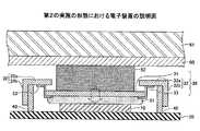
〔第2の実施の形態〕
次に、第2の実施の形態について説明する。本実施の形態は、図4に示されるように、シールドカバー外枠部32の上面32aの内側の面とシールドカバー上面部31の内側の面とを導電性弾性部材33により接続することにより、シールドカバー30が作製されている電子装置である。導電性弾性部材33による接続部分を変更しても、シールドカバー30が、シールドカバー外枠部32とシールドカバー上面部31が導電性弾性部材33により接続されていれば、第1の実施の形態と同様の効果を得ることができる。[Second Embodiment]
Next, a second embodiment will be described. In the present embodiment, as shown in FIG. 4, the inner surface of the
図5は、本実施の形態において、第2の熱接合部材52の厚さが設計厚みよりも厚く形成されていたり、間隔W2が設計値の中央値よりも狭く形成されている場合の状態を示す。これらの場合には、第1の実施の形態と同様に、硬い第2の熱接合部材52により、シールドカバー上面部31が押され、軟らかい第1の熱接合部材51が変形することにより、力が吸収される。 FIG. 5 shows a state where the thickness of the second
尚、上記以外の内容については、第1の実施の形態と同様である。 The contents other than the above are the same as in the first embodiment.
〔第3の実施の形態〕
次に、第3の実施の形態について説明する。本実施の形態は、図6に示されるように、シールドカバー外枠部32の上面32aの内側の面とシールドカバー上面部31の外側の面とを導電性弾性部材33により接続することにより、シールドカバー30が作製されている電子装置である。導電性弾性部材33による接続部分を変更しても、シールドカバー30が、シールドカバー外枠部32とシールドカバー上面部31が導電性弾性部材33により接続されていれば、第1の実施の形態と同様の効果を得ることができる。[Third Embodiment]
Next, a third embodiment will be described. In this embodiment, as shown in FIG. 6, the inner surface of the
図7は、本実施の形態において、第2の熱接合部材52の厚さが設計厚みよりも厚く形成されていたり、間隔W2が設計値の中央値よりも狭く形成されている場合の状態を示す。これらの場合には、第1の実施の形態と同様に、硬い第2の熱接合部材52により、シールドカバー上面部31が押され、軟らかい第1の熱接合部材51が変形することにより、力が吸収される。 FIG. 7 shows a state where the thickness of the second
尚、上記以外の内容については、第1の実施の形態と同様である。 The contents other than the above are the same as in the first embodiment.
〔第4の実施の形態〕
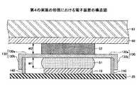
次に、第4の実施の形態における電子装置について説明する。本実施の形態における電子装置は、図8に示されるように、CPU等の半導体素子10が、プリント基板20にハンダ付けされており、半導体素子10の周囲には、シールドカバー130及び導電性弾性支柱部140が設けられている。シールドカバー130は、半導体素子10から発生する電磁波をシールドするため金属材料により形成されている。シールドカバー130が取り付けられる導電性弾性支柱部140は、半導体素子10を囲むように形成されて、プリント基板20に設置されており、接地電位に接続されている。本実施の形態においては、導電性弾性支柱部140は、導電性ゴム等により形成されており、導電性と弾性の双方の機能を備えている。[Fourth Embodiment]
Next, an electronic device according to a fourth embodiment will be described. As shown in FIG. 8, in the electronic device according to the present embodiment, a
シールドカバー130は、上面130aと側面130bとを有しており、シールドカバー130の側面130bを導電性弾性支柱部140にはめ込むことにより、プリント基板20に設置されている半導体素子10をシールドカバー130により覆うことができる。具体的には、シールドカバー130の側面130bは、導電性弾性支柱部140の外形よりも若干大きな形状で形成されており、導電性弾性支柱部140が内側となるように、シールドカバー130の側面130bをはめ込むことができるように形成されている。これにより、プリント基板20に取り付けられている半導体素子10をシールドカバー130により覆うことができる。 The
半導体素子10とシールドカバー130の上面130aとの間には、半導体素子10及びシールドカバー130の上面130aの内側の面と接触するように、第1の熱接合部材51が設けられている。また、シールドカバー130の上面130aと表示パネル61の裏面における金属板60との間には、シールドカバー130の上面130aの外側の面及び金属板60と接触するように、第2の熱接合部材52が設けられている。 A first
尚、導電性弾性支柱部140は、接地電位に接続されているため、導電性弾性支柱部140と側面130bにおいて接触しているシールドカバー130も接地電位となっている。このように、シールドカバー130を接地電位にすることにより、シールドカバー130において、半導体素子10を動作させた際に半導体素子10より発生する電磁波を遮蔽する効果を高めることができる。これにより、半導体素子10より発生した電磁波により、表示パネル61の表示等に及ぼす悪影響を抑制することができる。 Since the conductive
より詳細に本実施の形態の電子装置について説明する。具体的には、半導体素子10とシールドカバー130の上面130aとの間隔W1が0.4mm±0.1mm、シールドカバー130の上面130aと金属板60との間隔W2が0.4mm±0.1mmとなる設計値の場合について説明する。 The electronic device of this embodiment will be described in more detail. Specifically, the interval W1 between the
シールドカバー130は、厚さが約0.1mm厚のアルミニウム合金をプレス加工により、シールドカバー130の上面130aと側面130bとを形成することにより形成されている。導電性弾性支柱部140は、導電性のシリコンゴムにより形成されており、銀ペースト等の導電性接着剤により、プリント基板20に接続されている。 The
第1の熱接合部材51は、設計厚み0.5mmのTC−50SP−1.7(信越化学工業株式会社製:アスカーC硬度2)により形成されている。また、第2の熱接合部材52は、設計厚み0.5mmのTC−50CAT−20(信越化学工業株式会社製:アスカーC硬度20)により形成されている。従って、アスカーC硬度は、第2の熱接合部材52よりも第1の熱接合部材51が低くなっている。即ち、第1の熱接合部材51は、第2の熱接合部材52よりも軟らかい材料により形成される。尚、熱接合部材は、通常、5%〜20%圧縮して用いられるため、20%圧縮した際の厚さが設計値の中央値となる厚さとなるように形成されている。 The first
本実施の形態においては、第2の熱接合部材52の厚さが設計厚みよりも厚く形成されていたり、間隔W2が設計値の中央値よりも狭く形成されている場合には、図9に示されるように、第2の熱接合部材52により、シールドカバー130の上面130aが押される。このように、硬い第2の熱接合部材52により、シールドカバー130の上面130aが押されて動き、軟らかい第1の熱接合部材51が変形することにより、力が吸収される。これにより、表示パネル61に加わる力を抑制することができるため、表示パネル61における表示画面がにじむことを防ぐことができ、また、電子装置の外観等の変形を防ぐことができる。この際、導電性弾性支柱部140は伸縮性を有しており縮むが、シールドカバー130は、導電性弾性支柱部140と接触しており、シールドカバー130は接地電位の状態が保たれるため、電磁シールドとしての機能が損なわれることはない。 In the present embodiment, when the thickness of the second
尚、上記以外の内容については、第1の実施の形態と同様である。 The contents other than the above are the same as in the first embodiment.
〔第5の実施の形態〕
次に、第5の実施の形態における電子装置について説明する。本実施の形態における電子装置は、図10に示されるように、CPU等の半導体素子10は、プリント基板20にハンダ付けされており、半導体素子10の周囲には、シールドカバー230及びシールド支柱部40が設けられている。シールドカバー230が取り付けられるシールド支柱部40は、導電性を有する金属材料等により、半導体素子10を囲むように形成され、プリント基板20にハンダ付けされており、接地電位に接続されている。[Fifth Embodiment]
Next, an electronic device according to a fifth embodiment will be described. In the electronic device according to the present embodiment, as shown in FIG. 10, a
図11〜図14に基づきシールドカバー230について説明する。シールドカバー230は、上面の中央部分に上面部中央領域231、上面部中央領域231の周囲に上面部周辺領域232が形成されており、上面部中央領域231と上面部周辺領域232との間には、エキスパンドメタル領域233が形成されている。尚、図11は、シールドカバー230の上面図であり、図12は断面図であり、図12(a)は、エキスパンドメタル領域233が広がっていない状態、図12(b)は、エキスパンドメタル領域233が広がっている状態を示す。 The
シールドカバー230は、上面部周辺領域232の周囲が折り曲げられており側面部234が形成されている。エキスパンドメタル領域233は、図13(a)に示されるように、シールドカバー230の上面において複数の切り込み233aを設けることにより形成されている。本実施の形態においては、エキスパンドメタル領域233は、上面部中央領域231と上面部周辺領域232との間に6重の切り込み233aを設けることにより形成されている。尚、図10〜図15においては、便宜上、形成されている切り込み233aが4重の場合を示している。 The
これにより、シールドカバー230における上面部中央領域231に、上から力が加わることにより、エキスパンドメタル領域233において、切り込み233aの開口が広がり伸びる。尚、図14(a)は、図12(a)における状態のエキスパンドメタル領域233の断面の拡大図であり、図14(b)は、図12(b)における状態のエキスパンドメタル領域233の断面の拡大図である。 Accordingly, a force is applied to the upper surface
本実施の形態においては、シールドカバー230における側面部234をシールド支柱部40にはめ込むことにより、プリント基板20の上の半導体素子10をシールドカバー230により覆うことができるように形成されている。具体的には、シールドカバー230における側面部234は、シールド支柱部40の外形よりも若干大きな形状で形成されている。よって、シールド支柱部40が内側となるように、シールドカバー230における側面部234をはめ込むことができ、シールドカバー230における側面部234をはめ込むことにより、半導体素子10をシールドカバー230により覆うことができる。 In the present embodiment, the
半導体素子10とシールドカバー230における上面部中央領域231との間には、半導体素子10及びシールドカバー230における上面部中央領域231の内側の面と接触するように、第1の熱接合部材51が設けられている。また、シールドカバー230における上面部中央領域231と表示パネル61の裏面における金属板60との間には、シールドカバー230における上面部中央領域231の外側の面及び金属板60と接触するように、第2の熱接合部材52が設けられている。 Between the
尚、シールド支柱部40は、接地電位となっているため、シールド支柱部40と側面部234において接触しているシールドカバー230の全体も接地電位となっている。即ち、シールドカバー230における上面部中央領域231、上面部周辺領域232、エキスパンドメタル領域233、側面部234も接地電位となっている。このように、シールドカバー230の全体を接地電位にすることにより、シールドカバー230において、半導体素子10を動作させた際に半導体素子10より発生する電子波を遮蔽する効果を高めることができる。これにより、半導体素子10より発生した電磁波により、表示パネル61の表示等に及ぼす悪影響を抑制することができる。 In addition, since the shield support |
尚、シールドカバー230において、電磁シールドしようとするノイズとなる電磁波は、一般的には、周波数がMHz帯からGHz帯の電磁波である。このため、エキスパンドメタル領域233における切り込み233aにより形成される開口は、電磁波における波長の1/10以下であることが好ましい。例えば、周波数が100MHzの電磁波がノイズとなる場合、100MHzの電磁波の波長は3mmであるため、エキスパンドメタル領域233の切り込み233aの広がった開口が最大で0.3mmとなるように形成されていれば、十分なシールド効果が得られる。上記の場合、100MHzよりも低い周波数の電磁波では、波長はこれよりも長くなるため、100MHz以下の周波数の電磁波をすべて遮蔽することができる。従って、ノイズとなる電磁波のうち、最も周波数の高い電磁波に対応して切り込み233aを形成することにより、すべてのノイズとなる電磁波を遮蔽することができる。 Note that, in the
より詳細に本実施の形態の電子装置について説明する。具体的には、半導体素子10とシールドカバー230の上面部中央領域231との間隔W1が0.4mm±0.1mm、シールドカバー30の上面部中央領域231と金属板60との間隔W2が0.4mm±0.1mmとなる設計値の場合について説明する。 The electronic device of this embodiment will be described in more detail. Specifically, the interval W1 between the
シールドカバー230は、厚さが約0.1mm厚のアルミニウム合金により形成されており、プレス加工により作製されている。 The
第1の熱接合部材51は、設計厚み0.5mmのTC−50SP−1.7(信越化学工業株式会社製:アスカーC硬度2)により形成されている。第2の熱接合部材52は、設計厚み0.5mmのTC−50CAT−20(信越化学工業株式会社製:アスカーC硬度20)により形成されている。従って、アスカーC硬度は、第2の熱接合部材52よりも第1の熱接合部材51が低くなっている。即ち、第1の熱接合部材51は、第2の熱接合部材52よりも軟らかい材料により形成される。尚、熱接合部材は、通常、5%〜20%圧縮して用いられるため、20%圧縮した際の厚さが設計値の中央値となるように形成されている。 The first
本実施の形態においては、第2の熱接合部材52の厚さが設計厚みよりも厚く形成されていたり、間隔W2が設計値の中央値よりも狭く形成されている場合には、図15に示されるように、第2の熱接合部材52により、上面部中央領域231が押される。このように、硬い第2の熱接合部材52により、シールドカバー230における上面部中央領域231が押されて動き、軟らかい第1の熱接合部材51が変形することにより、力が吸収される。これにより、表示パネル61に加わる力を抑制することができるため、表示パネル61における表示画面がにじむことを防ぐことができ、また、電子装置の外観等の変形を防ぐことができる。この際、シールドカバー230における上面部中央領域231と上面部周辺領域232との間におけるエキスパンドメタル領域233が伸縮性を有しており伸びる。これにより、シールドカバー230における上面部中央領域231は接地電位の状態が保たれるため、電磁シールドとしての機能が損なわれることはない。 In the present embodiment, when the thickness of the second
〔第6の実施の形態〕
次に、第6の実施の形態における電子装置について説明する。本実施の形態における電子装置は、図16に示されるように、CPU等の半導体素子10が、プリント基板20にハンダ付けされており、半導体素子10の周囲には、シールドカバー30が設けられている。シールドカバー30は、半導体素子10から発生する電磁波をシールドするため金属材料により形成されている。シールドカバー30は、半導体素子10を囲むように形成され、プリント基板20に直接ハンダ付け等により取り付けられており、接地電位に接続されている。[Sixth Embodiment]
Next, an electronic device according to a sixth embodiment will be described. In the electronic device according to the present embodiment, as shown in FIG. 16, a
シールドカバー30は、上面の中央部分に設置されるシールドカバー上面部31と、上面の中央部分に開口が形成されているシールドカバー外枠部32とを有している。シールドカバー上面部31は、シールドカバー外枠部32における開口よりも若干大きな形状で形成されている。シールドカバー外枠部32は、中央に開口を有する上面32aと側面32bとにより形成されている。シールドカバー外枠部32とシールドカバー上面部31とは、シールドカバー外枠部32の上面32aにおける外側の面とシールドカバー上面部31における外側の面とが、導電性弾性部材33により接続されている。導電性弾性部材33は、導電性ゴム等の導電性を有する樹脂材料により形成されており、導電性と弾性の双方の機能を備えている。本実施の形態においては、シールドカバー30におけるシールドカバー外枠部32が、プリント基板20に直接ハンダ付け等により取り付けられている。 The
半導体素子10とシールドカバー上面部31との間には、半導体素子10及びシールドカバー上面部31の内側の面と接触するように、第1の熱接合部材51が設けられている。また、シールドカバー上面部31と表示パネル61の裏面における金属板60との間には、シールドカバー上面部31の外側の面及び金属板60と接触するように、第2の熱接合部材52が設けられている。 A first
尚、シールドカバー外枠部32は、接地電位に接続されているため、シールドカバー外枠部32と導電性弾性部材33により接続されているシールドカバー上面部31も接地電位となっている。このように、シールドカバー外枠部32及びシールドカバー上面部31を接地電位にすることにより、半導体素子10を動作させた際に半導体素子10より発生する電磁波をシールドカバー30において遮蔽する効果を高めることができる。これにより、半導体素子10より発生した電磁波により、表示パネル61の表示等に及ぼす悪影響を抑制することができる。 Since the shield cover
より詳細に本実施の形態の電子装置について説明する。具体的には、半導体素子10とシールドカバー30のシールドカバー上面部31との間隔W1が0.4mm±0.1mm、シールドカバー30のシールドカバー上面部31と金属板60との間隔W2が0.4mm±0.1mmとなる設計値の場合について説明する。 The electronic device of this embodiment will be described in more detail. Specifically, the interval W1 between the
シールドカバー30におけるシールドカバー外枠部32及びシールドカバー上面部31は、厚さが約0.1mm厚のアルミニウム合金により形成されている。 The shield cover
シールドカバー外枠部32と導電性弾性部材33との接続、及び、シールドカバー上面部31と導電性弾性部材33との接続は、熱圧着によりなされており、例えば、アマルファ(メック株式会社)により行ってもよい。 The connection between the shield cover
第1の熱接合部材51は、設計厚み0.5mmのTC−50SP−1.7(信越化学工業株式会社製:アスカーC硬度2)により形成されている。第2の熱接合部材52は、設計厚み0.5mmのTC−50CAT−20(信越化学工業株式会社製:アスカーC硬度20)により形成されている。 The first
本実施の形態においては、第2の熱接合部材52の厚さが設計厚みよりも厚く形成されていたり、間隔W2が設計値の中央値よりも狭く形成されている場合には、図17に示されるように、第2の熱接合部材52により、シールドカバー上面部31が押される。このように、硬い第2の熱接合部材52により、シールドカバー上面部31が押されて動き、軟らかい第1の熱接合部材51が変形することにより、力が吸収される。これにより、表示パネル61に加わる力を抑制することができるため、表示パネル61における表示画面がにじむことを防ぐことができ、また、電子装置の外観等の変形を防ぐことができる。この際、シールドカバー外枠部32とシールドカバー上面部31とを接続している伸縮性を有する導電性弾性部材33が伸びるため、シールドカバー上面部31は接地電位が保たれ、電磁シールドとしての機能が損なわれることはない。 In the present embodiment, when the thickness of the second
以上、実施の形態について詳述したが、特定の実施形態に限定されるものではなく、特許請求の範囲に記載された範囲内において、種々の変形及び変更が可能である。 Although the embodiment has been described in detail above, it is not limited to the specific embodiment, and various modifications and changes can be made within the scope described in the claims.
上記の説明に関し、更に以下の付記を開示する。
(付記1)
基板の上に設置された半導体素子を覆う、金属材料により形成されたシールドカバーであって、
上面の中央部分におけるシールドカバー上面部と、
前記上面の中央部分に開口を有するシールドカバー外枠部と、
を有し、前記シールドカバー上面部と前記シールドカバー外枠部は、導電性弾性部材により接続されており、
前記半導体素子と前記シールドカバー上面部との間には、前記半導体素子から前記シールドカバー上面部に熱を伝導させる第1の熱接合部材が設置され、
前記シールドカバー上面部と表示パネルの裏面に設けられた金属板との間には、前記シールドカバー上面部から前記金属板に熱を伝導させる第2の熱接合部材が設置されることを特徴とするシールドカバー。
(付記2)
前記導電性弾性部材は、導電性を有する樹脂材料により形成されていることを特徴とする付記1に記載のシールドカバー。
(付記3)
基板の上に設置された半導体素子を覆う、金属材料により形成されたシールドカバーであって、
上面の中央部分における上面部中央領域と、
前記上面部中央領域を囲む上面部周辺領域と、
前記上面部中央領域と前記上面部周辺領域との間に形成されたエキスパンドメタル領域と、
を有し、
前記エキスパンドメタル領域は、前記シールドカバーに複数の切り込みを設けることにより形成されており、
前記半導体素子と前記シールドカバーの前記上面部中央領域との間には、前記半導体素子から前記シールドカバーに熱を伝導させる第1の熱接合部材が設置され、
前記シールドカバーの前記上面部中央領域と表示パネルの裏面に設けられた金属板との間には、前記シールドカバーから前記金属板に熱を伝導させる第2の熱接合部材が設置されることを特徴とするシールドカバー。
(付記4)
前記シールドカバーは、前記半導体素子からの電磁波をシールドするものであることを特徴とする付記1から3のいずれかに記載のシールドカバー。
(付記5)
基板の上に設置された半導体素子と、
金属材料により形成された前記半導体素子を覆うシールドカバーと、
表示パネルの裏面に設けられた金属板と、
前記半導体素子と前記シールドカバーとの間に設置された前記半導体素子から前記シールドカバーに熱を伝導させる第1の熱接合部材と、
前記シールドカバーと前記金属板との間に設置された前記シールドカバーから前記金属板に熱を伝導させる第2の熱接合部材と、
を有し、
前記シールドカバーは、上面の中央部分におけるシールドカバー上面部と、前記上面の中央部分に開口を有するシールドカバー外枠部と、を有し、前記シールドカバー上面部と前記シールドカバー外枠部は、導電性弾性部材により接続されており、
前記第1の熱接合部材は、前記半導体素子と前記シールドカバー上面部との間に設置されており、
前記第2の熱接合部材は、前記シールドカバー上面部と前記金属板との間に設置されていることを特徴とする電子装置。
(付記6)
前記導電性弾性部材は、導電性を有する樹脂材料により形成されていることを特徴とする付記5に記載の電子装置。
(付記7)
基板の上に設置された半導体素子と、
金属材料により形成された前記半導体素子を覆うシールドカバーと、
表示パネルの裏面に設けられた金属板と、
前記半導体素子と前記シールドカバーとの間に設置された前記半導体素子から前記シールドカバーに熱を伝導させる第1の熱接合部材と、
前記シールドカバーと前記金属板との間に設置された前記シールドカバーから前記金属板に熱を伝導させる第2の熱接合部材と、
を有し、
前記シールドカバーは、上面の中央部分における上面部中央領域と、前記上面部中央領域を囲む上面部周辺領域と、前記上面部中央領域と前記上面部周辺領域との間に形成されたエキスパンドメタル領域とを有し、
前記エキスパンドメタル領域は、前記シールドカバーに複数の切り込みを設けることにより形成されており、
前記第1の熱接合部材は、前記半導体素子と前記シールドカバーの前記上面部中央領域との間に設置されており、
前記第2の熱接合部材は、前記シールドカバーの前記上面部中央領域と前記金属板との間に設置されていることを特徴とする電子装置。
(付記8)
前記基板には、導電性材料により形成されたシールド支柱部が設けられており、
前記シールド支柱部は、接地電位に接続されており、
前記シールドカバーは、前記シールド支柱部と接触して、前記シールド支柱部の一部又は全部を覆い設置されていることを特徴とする付記5から7のいずれかに記載の電子装置。
(付記9)
前記シールドカバーにおける側面が前記基板に接続され、接地電位に接続されていることを特徴とする付記5から7のいずれかに記載の電子装置。
(付記10)
基板の上に設置された半導体素子と、
金属材料により形成された前記半導体素子を覆うシールドカバーと、
表示パネルの裏面に設けられた金属板と、
前記半導体素子と前記シールドカバーとの間に設置された前記半導体素子から前記シールドカバーに熱を伝導させる第1の熱接合部材と、
前記シールドカバーと前記金属板との間に設置された前記シールドカバーから前記金属板に熱を伝導させる第2の熱接合部材と、
を有し、
前記基板には、導電性弾性部材により形成された導電性弾性支柱部が設けられており、
前記導電性弾性支柱部は、接地電位に接続されており、
前記シールドカバーは、前記導電性弾性支柱部と接触して、前記導電性弾性支柱部の一部又は全部を覆い設置されていることを特徴とする電子装置。
(付記11)
前記導電性弾性支柱部は、導電性を有する樹脂材料により形成されていることを特徴とする付記10に記載の電子装置。
(付記12)
前記第1の熱接合部材は、前記第2の熱接合部材よりも、硬度が低いことを特徴とする付記5から11のいずれかに記載の電子装置。
(付記13)
前記第1の熱接合部材及び前記第2の熱接合部材は、放熱シートであることを特徴とする付記5から12のいずれかに記載の電子装置。
(付記14)
前記表示パネルは、液晶パネルまたはエレクトロルミネッセンスパネルであることを特徴とする付記5から13のいずれかに記載の電子装置。In addition to the above description, the following additional notes are disclosed.
(Appendix 1)
A shield cover made of a metal material covering a semiconductor element installed on a substrate;
An upper surface portion of the shield cover in a central portion of the upper surface;
A shield cover outer frame portion having an opening in a central portion of the upper surface;
The shield cover upper surface part and the shield cover outer frame part are connected by a conductive elastic member,
Between the semiconductor element and the shield cover upper surface portion, a first thermal bonding member that conducts heat from the semiconductor element to the shield cover upper surface portion is installed,
Between the shield cover upper surface part and the metal plate provided on the back surface of the display panel, a second heat bonding member for conducting heat from the shield cover upper surface part to the metal plate is installed. Shield cover.
(Appendix 2)
The shield cover according to appendix 1, wherein the conductive elastic member is made of a conductive resin material.
(Appendix 3)
A shield cover made of a metal material covering a semiconductor element installed on a substrate;
A central region of the upper surface portion in the central portion of the upper surface;
An upper surface peripheral region surrounding the upper surface central region;
An expanded metal region formed between the upper surface central region and the upper surface peripheral region;
Have
The expanded metal region is formed by providing a plurality of cuts in the shield cover,
Between the semiconductor element and the central region of the upper surface portion of the shield cover, a first thermal bonding member that conducts heat from the semiconductor element to the shield cover is installed,
A second thermal bonding member that conducts heat from the shield cover to the metal plate is installed between the central region of the upper surface portion of the shield cover and the metal plate provided on the back surface of the display panel. Characteristic shield cover.
(Appendix 4)
The shield cover according to any one of appendices 1 to 3, wherein the shield cover shields electromagnetic waves from the semiconductor element.
(Appendix 5)
A semiconductor element installed on a substrate;
A shield cover that covers the semiconductor element formed of a metal material;
A metal plate provided on the back surface of the display panel;
A first thermal bonding member for conducting heat from the semiconductor element installed between the semiconductor element and the shield cover to the shield cover;
A second thermal bonding member for conducting heat from the shield cover installed between the shield cover and the metal plate to the metal plate;
Have
The shield cover includes a shield cover upper surface portion in a central portion of the upper surface, and a shield cover outer frame portion having an opening in the central portion of the upper surface, and the shield cover upper surface portion and the shield cover outer frame portion are Connected by a conductive elastic member,
The first thermal bonding member is installed between the semiconductor element and the shield cover upper surface part,
The second thermal bonding member is installed between the shield cover upper surface portion and the metal plate.
(Appendix 6)
The electronic device according to appendix 5, wherein the conductive elastic member is made of a conductive resin material.
(Appendix 7)
A semiconductor element installed on a substrate;
A shield cover that covers the semiconductor element formed of a metal material;
A metal plate provided on the back surface of the display panel;
A first thermal bonding member for conducting heat from the semiconductor element installed between the semiconductor element and the shield cover to the shield cover;
A second thermal bonding member for conducting heat from the shield cover installed between the shield cover and the metal plate to the metal plate;
Have
The shield cover includes an upper surface central region in a central portion of the upper surface, an upper surface peripheral region surrounding the upper surface central region, and an expanded metal region formed between the upper surface central region and the upper surface peripheral region. And
The expanded metal region is formed by providing a plurality of cuts in the shield cover,
The first thermal bonding member is installed between the semiconductor element and the central region of the upper surface portion of the shield cover,
The electronic device according to claim 1, wherein the second thermal bonding member is disposed between the central region of the upper surface portion of the shield cover and the metal plate.
(Appendix 8)
The substrate is provided with a shield post formed of a conductive material,
The shield post is connected to a ground potential;
The electronic device according to any one of appendices 5 to 7, wherein the shield cover is in contact with the shield support portion and is installed so as to cover part or all of the shield support portion.
(Appendix 9)
The electronic device according to any one of appendices 5 to 7, wherein a side surface of the shield cover is connected to the substrate and connected to a ground potential.
(Appendix 10)
A semiconductor element installed on a substrate;
A shield cover that covers the semiconductor element formed of a metal material;
A metal plate provided on the back surface of the display panel;
A first thermal bonding member for conducting heat from the semiconductor element installed between the semiconductor element and the shield cover to the shield cover;
A second thermal bonding member for conducting heat from the shield cover installed between the shield cover and the metal plate to the metal plate;
Have
The substrate is provided with a conductive elastic column portion formed of a conductive elastic member,
The conductive elastic strut portion is connected to a ground potential,
The electronic device according to claim 1, wherein the shield cover is in contact with the conductive elastic column portion and covers a part or all of the conductive elastic column portion.
(Appendix 11)
11. The electronic device according to
(Appendix 12)
The electronic device according to any one of appendices 5 to 11, wherein the first thermal bonding member has a lower hardness than the second thermal bonding member.
(Appendix 13)
The electronic device according to any one of appendices 5 to 12, wherein the first thermal bonding member and the second thermal bonding member are heat dissipation sheets.
(Appendix 14)
14. The electronic device according to any one of appendices 5 to 13, wherein the display panel is a liquid crystal panel or an electroluminescence panel.
10 半導体素子
20 プリント基板
30 シールドカバー
31 シールドカバー上面部
32 シールドカバー外枠部
32a シールドカバー外枠部の上面
32b シールドカバー外枠部の側面
33 導電性弾性部材
40 シールド支柱部
51 第1の熱接合部材
52 第2の熱接合部材
60 金属板
61 表示パネルDESCRIPTION OF
Claims (8)
Translated fromJapanese上面の中央部分におけるシールドカバー上面部と、
前記上面の中央部分に開口を有するシールドカバー外枠部と、
を有し、前記シールドカバー上面部と前記シールドカバー外枠部は、導電性弾性部材により接続されており、
前記半導体素子と前記シールドカバー上面部との間には、前記半導体素子から前記シールドカバー上面部に熱を伝導させる第1の熱接合部材が設置され、
前記シールドカバー上面部と表示パネルの裏面に設けられた金属板との間には、前記シールドカバー上面部から前記金属板に熱を伝導させる第2の熱接合部材が設置されることを特徴とするシールドカバー。A shield cover made of a metal material covering a semiconductor element installed on a substrate;
An upper surface portion of the shield cover in a central portion of the upper surface;
A shield cover outer frame portion having an opening in a central portion of the upper surface;
The shield cover upper surface part and the shield cover outer frame part are connected by a conductive elastic member,
Between the semiconductor element and the shield cover upper surface portion, a first thermal bonding member that conducts heat from the semiconductor element to the shield cover upper surface portion is installed,
Between the shield cover upper surface part and the metal plate provided on the back surface of the display panel, a second heat bonding member for conducting heat from the shield cover upper surface part to the metal plate is installed. Shield cover.
上面の中央部分における上面部中央領域と、
前記上面部中央領域を囲む上面部周辺領域と、
前記上面部中央領域と前記上面部周辺領域との間に形成されたエキスパンドメタル領域と、
を有し、
前記エキスパンドメタル領域は、前記シールドカバーに複数の切り込みを設けることにより形成されており、
前記半導体素子と前記シールドカバーの前記上面部中央領域との間には、前記半導体素子から前記シールドカバーに熱を伝導させる第1の熱接合部材が設置され、
前記シールドカバーの前記上面部中央領域と表示パネルの裏面に設けられた金属板との間には、前記シールドカバーから前記金属板に熱を伝導させる第2の熱接合部材が設置されることを特徴とするシールドカバー。A shield cover made of a metal material covering a semiconductor element installed on a substrate;
A central region of the upper surface portion in the central portion of the upper surface;
An upper surface peripheral region surrounding the upper surface central region;
An expanded metal region formed between the upper surface central region and the upper surface peripheral region;
Have
The expanded metal region is formed by providing a plurality of cuts in the shield cover,
Between the semiconductor element and the central region of the upper surface portion of the shield cover, a first thermal bonding member that conducts heat from the semiconductor element to the shield cover is installed,
A second thermal bonding member that conducts heat from the shield cover to the metal plate is installed between the central region of the upper surface portion of the shield cover and the metal plate provided on the back surface of the display panel. Characteristic shield cover.
金属材料により形成された前記半導体素子を覆うシールドカバーと、
表示パネルの裏面に設けられた金属板と、
前記半導体素子と前記シールドカバーとの間に設置された前記半導体素子から前記シールドカバーに熱を伝導させる第1の熱接合部材と、
前記シールドカバーと前記金属板との間に設置された前記シールドカバーから前記金属板に熱を伝導させる第2の熱接合部材と、
を有し、
前記シールドカバーは、上面の中央部分におけるシールドカバー上面部と、前記上面の中央部分に開口を有するシールドカバー外枠部と、を有し、前記シールドカバー上面部と前記シールドカバー外枠部は、導電性弾性部材により接続されており、
前記第1の熱接合部材は、前記半導体素子と前記シールドカバー上面部との間に設置されており、
前記第2の熱接合部材は、前記シールドカバー上面部と前記金属板との間に設置されていることを特徴とする電子装置。A semiconductor element installed on a substrate;
A shield cover that covers the semiconductor element formed of a metal material;
A metal plate provided on the back surface of the display panel;
A first thermal bonding member for conducting heat from the semiconductor element installed between the semiconductor element and the shield cover to the shield cover;
A second thermal bonding member for conducting heat from the shield cover installed between the shield cover and the metal plate to the metal plate;
Have
The shield cover includes a shield cover upper surface portion in a central portion of the upper surface, and a shield cover outer frame portion having an opening in the central portion of the upper surface, and the shield cover upper surface portion and the shield cover outer frame portion are Connected by a conductive elastic member,
The first thermal bonding member is installed between the semiconductor element and the shield cover upper surface part,
The second thermal bonding member is installed between the shield cover upper surface portion and the metal plate.
金属材料により形成された前記半導体素子を覆うシールドカバーと、
表示パネルの裏面に設けられた金属板と、
前記半導体素子と前記シールドカバーとの間に設置された前記半導体素子から前記シールドカバーに熱を伝導させる第1の熱接合部材と、
前記シールドカバーと前記金属板との間に設置された前記シールドカバーから前記金属板に熱を伝導させる第2の熱接合部材と、
を有し、
前記シールドカバーは、上面の中央部分における上面部中央領域と、前記上面部中央領域を囲む上面部周辺領域と、前記上面部中央領域と前記上面部周辺領域との間に形成されたエキスパンドメタル領域とを有し、
前記エキスパンドメタル領域は、前記シールドカバーに複数の切り込みを設けることにより形成されており、
前記第1の熱接合部材は、前記半導体素子と前記シールドカバーの前記上面部中央領域との間に設置されており、
前記第2の熱接合部材は、前記シールドカバーの前記上面部中央領域と前記金属板との間に設置されていることを特徴とする電子装置。A semiconductor element installed on a substrate;
A shield cover that covers the semiconductor element formed of a metal material;
A metal plate provided on the back surface of the display panel;
A first thermal bonding member for conducting heat from the semiconductor element installed between the semiconductor element and the shield cover to the shield cover;
A second thermal bonding member for conducting heat from the shield cover installed between the shield cover and the metal plate to the metal plate;
Have
The shield cover includes an upper surface central region in a central portion of the upper surface, an upper surface peripheral region surrounding the upper surface central region, and an expanded metal region formed between the upper surface central region and the upper surface peripheral region. And
The expanded metal region is formed by providing a plurality of cuts in the shield cover,
The first thermal bonding member is installed between the semiconductor element and the central region of the upper surface portion of the shield cover,
The electronic device according to claim 1, wherein the second thermal bonding member is disposed between the central region of the upper surface portion of the shield cover and the metal plate.
金属材料により形成された前記半導体素子を覆うシールドカバーと、
表示パネルの裏面に設けられた金属板と、
前記半導体素子と前記シールドカバーとの間に設置された前記半導体素子から前記シールドカバーに熱を伝導させる第1の熱接合部材と、
前記シールドカバーと前記金属板との間に設置された前記シールドカバーから前記金属板に熱を伝導させる第2の熱接合部材と、
を有し、
前記基板には、導電性弾性部材により形成された導電性弾性支柱部が設けられており、
前記導電性弾性支柱部は、接地電位に接続されており、
前記シールドカバーは、前記導電性弾性支柱部と接触して、前記導電性弾性支柱部の一部又は全部を覆い設置されていることを特徴とする電子装置。A semiconductor element installed on a substrate;
A shield cover that covers the semiconductor element formed of a metal material;
A metal plate provided on the back surface of the display panel;
A first thermal bonding member for conducting heat from the semiconductor element installed between the semiconductor element and the shield cover to the shield cover;
A second thermal bonding member for conducting heat from the shield cover installed between the shield cover and the metal plate to the metal plate;
Have
The substrate is provided with a conductive elastic column portion formed of a conductive elastic member,
The conductive elastic strut portion is connected to a ground potential,
The electronic device according to claim 1, wherein the shield cover is in contact with the conductive elastic column portion and covers a part or all of the conductive elastic column portion.
Priority Applications (1)
| Application Number | Priority Date | Filing Date | Title |
|---|---|---|---|
| JP2014231644AJP2016096249A (en) | 2014-11-14 | 2014-11-14 | Shield cover and electronic device |
Applications Claiming Priority (1)
| Application Number | Priority Date | Filing Date | Title |
|---|---|---|---|
| JP2014231644AJP2016096249A (en) | 2014-11-14 | 2014-11-14 | Shield cover and electronic device |
Publications (1)
| Publication Number | Publication Date |
|---|---|
| JP2016096249Atrue JP2016096249A (en) | 2016-05-26 |
Family
ID=56071894
Family Applications (1)
| Application Number | Title | Priority Date | Filing Date |
|---|---|---|---|
| JP2014231644APendingJP2016096249A (en) | 2014-11-14 | 2014-11-14 | Shield cover and electronic device |
Country Status (1)
| Country | Link |
|---|---|
| JP (1) | JP2016096249A (en) |
Cited By (17)
| Publication number | Priority date | Publication date | Assignee | Title |
|---|---|---|---|---|
| JP2018033594A (en)* | 2016-08-30 | 2018-03-08 | Hoya株式会社 | Processor for electronic endoscope and electronic endoscope system |
| WO2018088318A1 (en)* | 2016-11-11 | 2018-05-17 | 三菱電機株式会社 | Semiconductor device and manufacturing method therefor and wireless communication apparatus |
| FR3059466A1 (en)* | 2016-11-30 | 2018-06-01 | Sagemcom Broadband Sas | HEAT EXHAUST DEVICE |
| KR20190052334A (en)* | 2017-11-08 | 2019-05-16 | 에이엠텔레콤주식회사 | Radiant Heat Structure of Communication Apparatus |
| CN110140207A (en)* | 2016-12-26 | 2019-08-16 | 迪睿合电子材料有限公司 | Semiconductor device |
| WO2019193868A1 (en)* | 2018-04-04 | 2019-10-10 | デクセリアルズ株式会社 | Semiconductor device |
| JP2019220614A (en)* | 2018-06-21 | 2019-12-26 | デクセリアルズ株式会社 | Semiconductor device and semiconductor device manufacturing method |
| CN110730605A (en)* | 2018-07-16 | 2020-01-24 | 莱尔德电子材料(深圳)有限公司 | Shield, board level shield, apparatus and method |
| KR20200017115A (en)* | 2018-08-08 | 2020-02-18 | 삼성전자주식회사 | Electronic device including shielding member coupled with conductive plate covering opening of a shield can |
| CN111146163A (en)* | 2019-12-25 | 2020-05-12 | 苏州通富超威半导体有限公司 | Chip module and preparation method |
| JP2021044346A (en)* | 2019-09-10 | 2021-03-18 | Necプラットフォームズ株式会社 | Mounting board structure |
| JP2021174964A (en)* | 2020-04-30 | 2021-11-01 | 株式会社デンソー | Radar device |
| KR20220078088A (en)* | 2020-12-03 | 2022-06-10 | 주식회사 에이텍 | Structure for assembling IO shield on main board |
| WO2023112709A1 (en)* | 2021-12-14 | 2023-06-22 | オムロン株式会社 | Mounting board, and electric apparatus equipped with mounting board |
| WO2023153780A1 (en)* | 2022-02-08 | 2023-08-17 | 삼성전자 주식회사 | Heat dissipating structure and electronic apparatus including heat dissipating structure |
| WO2025005698A1 (en)* | 2023-06-28 | 2025-01-02 | 삼성전자 주식회사 | Electronic device comprising heat-dissipating member |
| US12238911B2 (en) | 2021-11-12 | 2025-02-25 | Samsung Electronics Co., Ltd. | Electronic device including sheilding structure |
- 2014
- 2014-11-14JPJP2014231644Apatent/JP2016096249A/enactivePending
Cited By (35)
| Publication number | Priority date | Publication date | Assignee | Title |
|---|---|---|---|---|
| JP2018033594A (en)* | 2016-08-30 | 2018-03-08 | Hoya株式会社 | Processor for electronic endoscope and electronic endoscope system |
| WO2018088318A1 (en)* | 2016-11-11 | 2018-05-17 | 三菱電機株式会社 | Semiconductor device and manufacturing method therefor and wireless communication apparatus |
| JPWO2018088318A1 (en)* | 2016-11-11 | 2019-10-03 | 三菱電機株式会社 | Semiconductor device, method for manufacturing the same, and wireless communication device |
| US11081449B2 (en) | 2016-11-11 | 2021-08-03 | Mitsubishi Electric Corporation | Semiconductor device and method for manufacturing the same and wireless communication apparatus |
| US10665527B2 (en) | 2016-11-30 | 2020-05-26 | Sagemcom Broadband Sas | Device for removing heat |
| FR3059466A1 (en)* | 2016-11-30 | 2018-06-01 | Sagemcom Broadband Sas | HEAT EXHAUST DEVICE |
| WO2018099729A1 (en)* | 2016-11-30 | 2018-06-07 | Sagemcom Broadband Sas | Device for removing heat |
| CN110140207A (en)* | 2016-12-26 | 2019-08-16 | 迪睿合电子材料有限公司 | Semiconductor device |
| CN110140207B (en)* | 2016-12-26 | 2023-08-01 | 迪睿合电子材料有限公司 | Semiconductor device with a semiconductor device having a plurality of semiconductor chips |
| KR20190052334A (en)* | 2017-11-08 | 2019-05-16 | 에이엠텔레콤주식회사 | Radiant Heat Structure of Communication Apparatus |
| JP7213621B2 (en) | 2018-04-04 | 2023-01-27 | デクセリアルズ株式会社 | semiconductor equipment |
| US11322425B2 (en) | 2018-04-04 | 2022-05-03 | Dexerials Corporation | Semiconductor device |
| WO2019193868A1 (en)* | 2018-04-04 | 2019-10-10 | デクセリアルズ株式会社 | Semiconductor device |
| JP2019186310A (en)* | 2018-04-04 | 2019-10-24 | デクセリアルズ株式会社 | Semiconductor device |
| JP7208720B2 (en) | 2018-06-21 | 2023-01-19 | デクセリアルズ株式会社 | Semiconductor device and method for manufacturing semiconductor device |
| WO2019244950A1 (en)* | 2018-06-21 | 2019-12-26 | デクセリアルズ株式会社 | Semiconductor device and method for producing semiconductor device |
| JP2019220614A (en)* | 2018-06-21 | 2019-12-26 | デクセリアルズ株式会社 | Semiconductor device and semiconductor device manufacturing method |
| US11329005B2 (en) | 2018-06-21 | 2022-05-10 | Dexerials Corporation | Semiconductor device and method of producing the same |
| CN110730605A (en)* | 2018-07-16 | 2020-01-24 | 莱尔德电子材料(深圳)有限公司 | Shield, board level shield, apparatus and method |
| KR102538757B1 (en)* | 2018-08-08 | 2023-06-01 | 삼성전자 주식회사 | Electronic device including shielding member coupled with conductive plate covering opening of a shield can |
| EP3811747A4 (en)* | 2018-08-08 | 2021-10-13 | Samsung Electronics Co., Ltd. | ELECTRONIC DEVICE WITH A SHIELD ELEMENT CONNECTED TO A CONDUCTIVE PLATE COVERING THE OPENING OF THE SHIELD LID |
| CN112514546A (en)* | 2018-08-08 | 2021-03-16 | 三星电子株式会社 | Electronic device including shield member connected to conductive plate covering shield case opening |
| KR20200017115A (en)* | 2018-08-08 | 2020-02-18 | 삼성전자주식회사 | Electronic device including shielding member coupled with conductive plate covering opening of a shield can |
| CN112514546B (en)* | 2018-08-08 | 2024-03-08 | 三星电子株式会社 | Electronic equipment containing shielding components |
| JP2021044346A (en)* | 2019-09-10 | 2021-03-18 | Necプラットフォームズ株式会社 | Mounting board structure |
| CN111146163A (en)* | 2019-12-25 | 2020-05-12 | 苏州通富超威半导体有限公司 | Chip module and preparation method |
| JP2021174964A (en)* | 2020-04-30 | 2021-11-01 | 株式会社デンソー | Radar device |
| KR102601885B1 (en)* | 2020-12-03 | 2023-11-15 | 주식회사 에이텍 | Structure for assembling IO shield on main board |
| KR20220078088A (en)* | 2020-12-03 | 2022-06-10 | 주식회사 에이텍 | Structure for assembling IO shield on main board |
| US12238911B2 (en) | 2021-11-12 | 2025-02-25 | Samsung Electronics Co., Ltd. | Electronic device including sheilding structure |
| WO2023112709A1 (en)* | 2021-12-14 | 2023-06-22 | オムロン株式会社 | Mounting board, and electric apparatus equipped with mounting board |
| JP2023087808A (en)* | 2021-12-14 | 2023-06-26 | オムロン株式会社 | Mounting substrates and electrical equipment mounted with mounting substrates |
| EP4425543A4 (en)* | 2021-12-14 | 2025-09-17 | Omron Tateisi Electronics Co | MOUNTING PLATE AND ELECTRICAL DEVICE WITH THE MOUNTING PLATE |
| WO2023153780A1 (en)* | 2022-02-08 | 2023-08-17 | 삼성전자 주식회사 | Heat dissipating structure and electronic apparatus including heat dissipating structure |
| WO2025005698A1 (en)* | 2023-06-28 | 2025-01-02 | 삼성전자 주식회사 | Electronic device comprising heat-dissipating member |
Similar Documents
| Publication | Publication Date | Title |
|---|---|---|
| JP2016096249A (en) | Shield cover and electronic device | |
| JP6707960B2 (en) | Electronics | |
| US10497641B2 (en) | Heat dissipation assembly and electronic device | |
| CN108141996B (en) | Flexible Electromagnetic Interference (EMI) Shield | |
| JP5967206B2 (en) | Electronics | |
| US20160242331A1 (en) | Electromagnetic shield structure for electronic device | |
| US20240324093A1 (en) | Circuit board assembly and electronic device | |
| US9389029B2 (en) | Heat transfer structure | |
| TW201626866A (en) | Electronic circuit board assembly including EMI shielding structure and thermal pad | |
| US10244668B2 (en) | Heat dissipating structure and electronic apparatus | |
| US20170163302A1 (en) | Heat transfer electromagnetic interference shield | |
| WO2020153068A1 (en) | Antenna module and communication device | |
| CN106304817A (en) | Electronic device | |
| CN104219933B (en) | Heat radiation mechanism of electronic device | |
| WO2014020787A1 (en) | Electronic component module and mounting body therefor | |
| US20240284636A1 (en) | Electronic Device | |
| US9391029B2 (en) | Electronic device | |
| US12353259B2 (en) | Touch module and terminal device | |
| JP2013171932A (en) | Heat radiator of electronic apparatus | |
| TWI547237B (en) | Shielding structure for emi-preventing of electronic component | |
| KR102538390B1 (en) | Radiating device for displaying apparatus and its manufacturing method | |
| KR20160004786A (en) | Semiconductor package module | |
| CN110446405B (en) | Flexible shielding cover and electronic device applying same | |
| TWI501467B (en) | Antenna integrated isolation hood and electronic device | |
| CN111107737B (en) | Shield case structure and electronic device |