JP2016095378A - Multi-display device, display, and image display method - Google Patents
Multi-display device, display, and image display methodDownload PDFInfo
- Publication number
- JP2016095378A JP2016095378AJP2014230978AJP2014230978AJP2016095378AJP 2016095378 AJP2016095378 AJP 2016095378AJP 2014230978 AJP2014230978 AJP 2014230978AJP 2014230978 AJP2014230978 AJP 2014230978AJP 2016095378 AJP2016095378 AJP 2016095378A
- Authority
- JP
- Japan
- Prior art keywords
- pixel
- line
- display
- lines
- image
- Prior art date
- Legal status (The legal status is an assumption and is not a legal conclusion. Google has not performed a legal analysis and makes no representation as to the accuracy of the status listed.)
- Granted
Links
Images


Landscapes
- Liquid Crystal Display Device Control (AREA)
- Control Of Indicators Other Than Cathode Ray Tubes (AREA)
- Liquid Crystal (AREA)
Abstract
Description
Translated fromJapanese本発明は、複数のディスプレイを用いて画像を表示するマルチディスプレイ装置、単一のディスプレイ、及びマルチディスプレイ装置を用いて画像を表示する方法に関する。 The present invention relates to a multi-display device that displays an image using a plurality of displays, a single display, and a method for displaying an image using the multi-display device.
複数のディスプレイを二次元状に並べてより大画面のディスプレイを構成したマルチディスプレイ装置がある。各ディスプレイが画像を表示することにより、複数の画像を組み合わせた一つの大画像がマルチディスプレイ装置に表示される。特許文献1には、マルチディスプレイ装置の例が開示されている。 There are multi-display devices in which a plurality of displays are arranged two-dimensionally to form a larger screen display. Each display displays an image, so that one large image obtained by combining a plurality of images is displayed on the multi-display device.
ディスプレイに表示される画像は、縦横に並んだ複数の画素からなる。より詳しくは、画像は、複数の画素が横方向に並んでなる画素ラインが縦に複数個並んでなる。ディスプレイに画像を表示する際には、各画素ラインを順次的に表示する。より詳しくは、一端にある画素ラインに含まれる画素が表示され、次に、隣接する二番目の画素ラインに含まれる画素が表示され、順次的に各画素ラインが表示され、最後に、他端にある画素ラインに含まれる画素が表示される。このため、二つの画素ラインが表示される時点の間には時間差が発生する。画像に含まれる画素ラインの数をNとすると、二つの画素ラインが表示される時点間の時間差は、複数の画素ラインの一端に存在し最初に表示される第1画素ラインと、他端に存在し最後に表示される第N画素ラインとの間で最も大きくなる。 An image displayed on the display is composed of a plurality of pixels arranged vertically and horizontally. More specifically, in the image, a plurality of pixel lines in which a plurality of pixels are arranged in the horizontal direction are arranged in the vertical direction. When an image is displayed on the display, each pixel line is sequentially displayed. More specifically, the pixels included in the pixel line at one end are displayed, then the pixels included in the adjacent second pixel line are displayed, each pixel line is displayed sequentially, and finally the other end The pixels included in the pixel line are displayed. For this reason, a time difference occurs between the time points when the two pixel lines are displayed. Assuming that the number of pixel lines included in the image is N, the time difference between the time points when the two pixel lines are displayed is the first pixel line that exists at one end of the plurality of pixel lines and is displayed at the other end. It becomes the largest among the Nth pixel lines that exist and are displayed last.
複数のディスプレイを縦に並べたマルチディスプレイ装置では、隣接する二つのディスプレイの境界部分において、一方のディスプレイが表示する画像に含まれる第N画素ラインと他方のディスプレイが表示する画像に含まれる第1画素ラインとが近接することになる。マルチディスプレイ装置で画像を表示する際、二つのディスプレイの境界部分では、近接している第1画素ラインと第N画素ラインとが表示される時間差が大きいので、画像の乱れが発生する。特に、マルチディスプレイ装置で動画を表示する場合には、二つのディスプレイの境界部分で画像のずれが発生する。 In the multi-display device in which a plurality of displays are arranged vertically, the first pixel included in the image displayed by the Nth pixel line included in the image displayed by one display and the image displayed by the other display at the boundary portion between two adjacent displays. The pixel line is in close proximity. When an image is displayed on the multi-display device, the boundary between the two displays has a large time difference in which the adjacent first pixel line and the Nth pixel line are displayed, resulting in image disturbance. In particular, when a moving image is displayed on a multi-display device, an image shift occurs at the boundary between two displays.
本発明は、斯かる事情に鑑みてなされたものであって、その目的とするところは、ディスプレイの境界部分での画像の乱れの発生を防止したマルチディスプレイ装置、ディスプレイ及び画像表示方法を提供することにある。 The present invention has been made in view of such circumstances, and an object of the present invention is to provide a multi-display device, a display, and an image display method that prevent the occurrence of image disturbance at the boundary portion of the display. There is.
本発明に係るマルチディスプレイ装置は、夫々に複数の画素が横方向に並んだ複数の画素ラインが縦方向に並んでなる画像を夫々に表示する複数のディスプレイを少なくとも縦方向に配列してあり、各ディスプレイは画像の表示時に各画素ラインを順次的に表示するマルチディスプレイ装置において、各ディスプレイは、画像を表示する際に複数の画素ラインの夫々を順次的に表示する順番を、一端の画素ラインを最初に表示して他端の画素ラインを最後に表示する順番とは異なる順番にしてあることを特徴とする。 In the multi-display device according to the present invention, a plurality of displays each displaying an image in which a plurality of pixel lines each having a plurality of pixels arranged in the horizontal direction are arranged in the vertical direction are arranged at least in the vertical direction, In a multi-display device in which each display sequentially displays each pixel line when displaying an image, each display sequentially displays the order of displaying each of the plurality of pixel lines when displaying an image. In the order different from the order in which the pixel lines at the other end are displayed first and the pixel lines at the other end are displayed last.
本発明に係るマルチディスプレイ装置は、各ディスプレイは、画像の表示時に、前記複数の画素ラインの内、両端の画素ラインを除く特定の画素ラインを最初に表示し、前記特定の画素ラインから両端の画素ラインに向けて順次的に各画素ラインを表示するように構成してあることを特徴とする。 In the multi-display apparatus according to the present invention, each display first displays a specific pixel line excluding the pixel lines at both ends of the plurality of pixel lines at the time of displaying an image. Each pixel line is sequentially displayed toward the pixel line.
本発明に係るマルチディスプレイ装置は、各ディスプレイは、画像に含まれる各画素を表示するための複数の素子がマトリクス状に配列されており、各画素ラインに対応する複数の素子に夫々接続された複数の信号線を含む回路と、前記複数の信号線の夫々へ前記複数の素子を動作させるための信号を供給するドライバとを備え、前記ドライバは、画像の表示時に、前記特定の画素ラインに対応する複数の素子に接続された信号線へ最初に信号を供給し、両端の画素ラインに対応する複数の素子に接続された信号線に向けて順次的に各信号線へ信号を供給するように構成してあることを特徴とする。 In the multi-display device according to the present invention, in each display, a plurality of elements for displaying each pixel included in the image are arranged in a matrix, and each display is connected to a plurality of elements corresponding to each pixel line. A circuit including a plurality of signal lines; and a driver for supplying a signal for operating the plurality of elements to each of the plurality of signal lines. The driver applies the specific pixel line to an image when displaying an image. A signal is first supplied to a signal line connected to a plurality of corresponding elements, and a signal is sequentially supplied to each signal line toward a signal line connected to the plurality of elements corresponding to the pixel lines at both ends. It is comprised by these.
本発明に係るマルチディスプレイ装置は、各ディスプレイは、画像の表示時に、前記複数の画素ラインの内、一端の画素ラインを最初に表示し、他端の画素ラインを次に表示し、両端の画素ラインから中央側の画素ラインに向けて、前記一端に近い画素ラインと前記他端に近い画素ラインとを交互に表示しながら、順次的に各画素ラインを表示するように構成してあることを特徴とする。 In the multi-display apparatus according to the present invention, each display displays a pixel line at one end first among the plurality of pixel lines, and then displays a pixel line at the other end when displaying an image. From the line toward the center pixel line, the pixel line close to the one end and the pixel line close to the other end are alternately displayed, and each pixel line is sequentially displayed. Features.
本発明に係るマルチディスプレイ装置は、各ディスプレイは、画像に含まれる各画素を表示するための複数の素子がマトリクス状に配列されており、各画素ラインに対応する複数の素子に夫々接続された複数の信号線を含む回路と、前記複数の信号線の夫々へ前記複数の素子を動作させるための信号を供給するドライバとを備え、前記ドライバは、画像の表示時に、前記一端の画素ラインに対応する複数の素子に接続された信号線へ最初に信号を供給し、前記他端の画素ラインに対応する複数の素子に接続された信号線へ次に信号を供給し、両端の画素ラインに対応する複数の素子に接続された信号線から中央側の画素ラインに対応する複数の素子に接続された信号線に向けて、前記一端に近い画素ラインに対応する複数の素子に接続された信号線と前記他端に近い画素ラインに対応する複数の素子に接続された信号線とへ交互に信号を供給しながら、順次的に各信号線へ信号を供給するように構成してあることを特徴とする。 In the multi-display device according to the present invention, in each display, a plurality of elements for displaying each pixel included in the image are arranged in a matrix, and each display is connected to a plurality of elements corresponding to each pixel line. A circuit including a plurality of signal lines; and a driver for supplying a signal for operating the plurality of elements to each of the plurality of signal lines. The driver is connected to the pixel line at the one end during image display. A signal is first supplied to a signal line connected to a plurality of corresponding elements, a signal is then supplied to a signal line connected to a plurality of elements corresponding to the pixel line on the other end, and the pixel lines on both ends are supplied. Connected to a plurality of elements corresponding to a pixel line close to the one end from a signal line connected to a plurality of corresponding elements toward a signal line connected to a plurality of elements corresponding to the central pixel line A signal is sequentially supplied to each signal line while alternately supplying a signal to a signal line connected to a plurality of elements corresponding to the pixel line and the pixel line close to the other end. Features.
本発明に係るディスプレイは、夫々に複数の画素が横方向に並んだ複数の画素ラインが縦方向に並んでなる画像を表示するために、各画素ラインを順次的に表示するディスプレイにおいて、複数の画素ラインの夫々を順次的に表示する順番を、一端の画素ラインを最初に表示して他端の画素ラインを最後に表示する順番とは異なる順番にしてあることを特徴とする。 The display according to the present invention is a display that sequentially displays each pixel line in order to display an image in which a plurality of pixel lines each having a plurality of pixels arranged in the horizontal direction are arranged in the vertical direction. The order in which each of the pixel lines is sequentially displayed is different from the order in which the pixel line at one end is displayed first and the pixel line at the other end is displayed last.
本発明に係る画像表示方法は、夫々に複数の画素が横方向に並んだ複数の画素ラインが縦方向に並んでなる画像を夫々に表示する複数のディスプレイを少なくとも縦方向に配列してあり、各ディスプレイは画像の表示時に各画素ラインを順次的に表示するマルチディスプレイ装置で、画像を表示する方法において、各ディスプレイは、前記複数の画素ラインの内、両端の画素ラインを除く特定の画素ラインを最初に表示し、前記特定の画素ラインから両端の画素ラインに向けて順次的に各画素ラインを表示することを特徴とする。 In the image display method according to the present invention, a plurality of displays each displaying an image in which a plurality of pixel lines each having a plurality of pixels arranged in the horizontal direction are arranged in the vertical direction are arranged at least in the vertical direction, Each display is a multi-display device that sequentially displays each pixel line when displaying an image. In the method for displaying an image, each display is a specific pixel line excluding the pixel lines at both ends of the plurality of pixel lines. Are first displayed, and each pixel line is sequentially displayed from the specific pixel line toward the pixel lines at both ends.
本発明に係る画像表示方法は、夫々に複数の画素が横方向に並んだ複数の画素ラインが縦方向に並んでなる画像を夫々に表示する複数のディスプレイを少なくとも縦方向に配列してあり、各ディスプレイは画像の表示時に各画素ラインを順次的に表示するマルチディスプレイ装置で、画像を表示する方法において、各ディスプレイは、前記複数の画素ラインの内、一端の画素ラインを最初に表示し、他端の画素ラインを次に表示し、両端の画素ラインから中央側の画素ラインに向けて、前記一端に近い画素ラインと前記他端に近い画素ラインとを交互に表示しながら、順次的に各画素ラインを表示することを特徴とする。 In the image display method according to the present invention, a plurality of displays each displaying an image in which a plurality of pixel lines each having a plurality of pixels arranged in the horizontal direction are arranged in the vertical direction are arranged at least in the vertical direction, Each display is a multi-display device that sequentially displays each pixel line when displaying an image. In the method for displaying an image, each display first displays a pixel line at one end of the plurality of pixel lines, The other pixel line is displayed next, and the pixel lines close to the one end and the pixel lines close to the other end are alternately displayed from the pixel lines at both ends toward the central pixel line, and sequentially. Each pixel line is displayed.
本発明にあっては、マルチディスプレイ装置は、複数のディスプレイの境界部分において乱れの無い画像を表示することが可能であり、動画を表示する際にも、画像のずれの発生を防止することが可能である等、優れた効果を奏する。 In the present invention, the multi-display device can display an image without disturbance at a boundary portion between a plurality of displays, and can prevent the occurrence of image shift even when displaying a moving image. It has excellent effects such as being possible.
以下本発明をその実施形態を示す図面に基づき具体的に説明する。
(実施形態1)
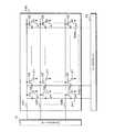
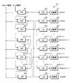
図1は、マルチディスプレイ装置の構成を示すブロック図である。マルチディスプレイ装置は、例えば、店舗又は公共スペース等に設置され、ニュース又は広告等の各種の情報を表す画像を表示する情報ディスプレイである。マルチディスプレイ装置は、複数のディスプレイ1を備えている。ディスプレイ1は、液晶パネルを用いて画像を表示する液晶ディスプレイであり、正面視で矩形に形成されている。複数のディスプレイ1は、画像表示方向を同一方向にして少なくとも縦方向に配列されており、全体で矩形をなしている。複数のディスプレイ1が組み合わさることにより、矩形の巨大なディスプレイが構成されている。なお、図中には縦に三個のディスプレイ1を配列した例を示したが、マルチディスプレイ装置は、二個のディスプレイ1が配列された形態でもよく、四個以上のディスプレイ1が配列された形態でもよい。また、マルチディスプレイ装置は、横方向にも複数のディスプレイ1が配列された形態であってもよい。Hereinafter, the present invention will be specifically described with reference to the drawings illustrating embodiments thereof.
(Embodiment 1)
FIG. 1 is a block diagram illustrating a configuration of a multi-display device. The multi-display device is an information display that is installed in, for example, a store or a public space, and displays images representing various types of information such as news or advertisements. The multi-display device includes a plurality of
マルチディスプレイ装置は、外部から画像データを入力される入力部22と、画像処理を行う画像処理部21とを備えている。画像処理部21には、複数のディスプレイ1の夫々が接続されている。画像処理部21は、入力部22に入力された画像データが表す画像の大きさを拡大し、拡大した画像を複数の部分画像に分割する。複数の部分画像の夫々は、複数のディスプレイ1のいずれか一つが表示すべき画像である。画像処理部21は、各ディスプレイ1が表示すべき部分画像を表すデータを各ディスプレイ1へ入力する。 The multi-display apparatus includes an
図2は、ディスプレイ1の構成を示すブロック図である。ディスプレイ1は、液晶パネル11と、液晶パネル11の背後に配置されたバックライト14とを備えている。液晶パネル11は、背後からバックライト14に照明され、画像を表示する。液晶パネル11は、液晶層と、カラーフィルタと、液晶層に電圧を印加するための電極層及びアクティブマトリクス回路と、二枚の偏光板とを含んで構成されている。 FIG. 2 is a block diagram showing the configuration of the
図3は、アクティブマトリクス回路の構成を示す模式的回路図である。アクティブマトリクス回路110では、複数の信号線が格子状に配線されている。また、画素に対応する液晶に電圧を印加する複数の画素電極31がマトリクス状に配置されている。夫々の画素電極31は信号線の交差点に対応している。各画素電極31にはTFT(thin film transistor)等のアクティブ素子32が接続されている。各アクティブ素子32は各画素電極31が対応する交差点で交差した二本の信号線に接続されている。アクティブ素子32がTFTである場合、横方向に沿った信号線にアクティブ素子32のゲートが接続されており、縦方向に沿った信号線にアクティブ素子32のソースが接続されている。横方向に沿った信号線をゲート線と言い、縦方向に沿った信号線をソース線と言う。ディスプレイ1が表示する画像に含まれる画素の数を、縦方向にN個、横方向にM個とする。画素電極31及びアクティブ素子32は、縦方向にN個、横方向にM個並んでいる。また、N本のゲート線331〜33Nが平行に配線され、M本のソース線341〜34Mが平行に配線されている。いずれかのゲート線及びソース線に信号が流れることにより、ゲート線及びソース線に接続されたアクティブ素子32がオン状態となり、アクティブ素子32に接続された画素電極31が動作し、液晶に電圧を印加する。夫々のゲート線は、ディスプレイ1で表示すべき画像に含まれる夫々の画素ラインに含まれる複数の画素に対応する複数の画素電極31にアクティブ素子32を介して接続されている。一のゲート線に信号が流れ、並行して各ソース線に信号が流れた場合は、一の画素ラインに含まれる画素に対応する画素電極31が動作し、一の画素ラインが表示される。 FIG. 3 is a schematic circuit diagram showing the configuration of the active matrix circuit. In the
ディスプレイ1は、複数のゲート線に接続されたゲートドライバ12と、複数のソース線に接続されたソースドライバ13とを備えている。ゲートドライバ12は、複数のゲート線に供給するための信号を生成し、生成した信号を順次各ゲート線へ供給する。ソースドライバ13は、複数のソース線に供給するための信号を生成し、生成した信号を順次各ソース線に供給する。また、ディスプレイ1は、制御部16と、画像の表示タイミングを制御するタイミングコントローラ15と備えている。タイミングコントローラ15は、制御部16に接続されており、ゲートドライバ12及びソースドライバ13が接続されている。制御部16は、画像処理部21に接続されており、部分画像を表すデータを画像処理部21から入力される。制御部16は、入力されたデータを調整し、調整したデータをタイミングコントローラ15へ入力する。タイミングコントローラ15は、制御部16から入力されたデータを、ゲートドライバ12及びソースドライバ13を駆動用信号へ変換し、駆動用信号をゲートドライバ12及びソースドライバ13へ入力する。ゲートドライバ12及びソースドライバ13が駆動用信号に応じて駆動し、各画素に対応する画素電極31が動作し、各画素が表示され、画像が表示される。 The
ディスプレイ1は、電源部18と、バックライト14へ電力を供給するバックライト用ドライバ17とを備えている。電源部18は、マルチディスプレイ装置が備える図示しない電源、又はマルチディスプレイ装置外の電源から電力を供給される。電源部18は、バックライトドライバ17、制御部16、タイミングコントローラ15、ゲートドライバ12及びソースドライバ13へ駆動用の電力を供給する。バックライト用ドライバ17は、電源部18からの電力をバックライト14点灯用の電力へ変換し、変換した電力をバックライト14へ供給する。 The
従来のマルチディスプレイ装置を用いた従来の画像表示方法を説明する。図4は、従来のゲートドライバの構成を示すブロック図である。Nは偶数であり、N/2=Hとする。ゲートドライバは、N個のシフトレジスタ(SR)、レベルシフタ(LS)及び供給部を含んでいる。タイミングコントローラから、各シフトレジスタへクロック信号が入力され、第1のシフトレジスタ711へトリガ信号が入力される。シフトレジスタ711は、トリガ信号の入力に応じて、信号を第1のレベルシフタ721へ入力し、レベルシフタ721は入力された信号のレベルを変換して第1の供給部731へ入力し、供給部731は第1ゲート線へ信号を供給する。第1ゲート線は、ディスプレイで表示すべき画像に含まれる第1画素ラインに含まれる複数の画素に対応する複数の画素電極にアクティブ素子を介して接続されている。第1ゲート線へ信号が供給されている状態で、ソースドライバは、各ソース線へ信号を供給する。これにより、第1ゲート線にアクティブ素子を介して接続されている画素電極が動作し、第1画素ラインに含まれる画素が表示される。このように、第1画素ラインが表示される。 A conventional image display method using a conventional multi-display device will be described. FIG. 4 is a block diagram showing a configuration of a conventional gate driver. N is an even number, and N / 2 = H. The gate driver includes N shift registers (SR), a level shifter (LS), and a supply unit. A clock signal is input from the timing controller to each shift register, and a trigger signal is input to the
シフトレジスタ711は、第2のシフトレジスタ712へトリガ信号を入力する。シフトレジスタ712は、信号を第2のレベルシフタ722へ入力し、レベルシフタ722は信号を第2の供給部732へ入力し、供給部732は第2ゲート線へ信号を供給する。この結果、第2画素ラインが表示される。同様にして、nを1〜Nの自然数として、第(n−1)のシフトレジスタは、第nのシフトレジスタへトリガ信号を入力し、第nのシフトレジスタは、信号を第nのレベルシフタへ入力し、第nのレベルシフタは信号を第nの供給部へ入力し、第nの供給部は第nゲート線へ信号を供給する。この結果、第n画素ラインが表示される。以上のようにして、第1画素ラインから第N画素ラインまで順に表示され、この結果、ディスプレイに画像が表示される。複数のディスプレイの夫々において、同様の方法で画像が表示される。 The
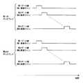
図5は、従来のマルチディスプレイ装置において各ゲート線への信号の供給タイミングを模式的に示すタイミングチャートである。第1のディスプレイ及び第2のディスプレイが縦方向に並んでいるとし、各ディスプレイにおける各ゲート線への信号の供給タイミングを示している。図中の横軸は時間であり、ゲート線に信号が供給されている状態を縦軸のハイで示している。第1及び第2のディスプレイの夫々において、画像が表示される際には、第1ゲート線から第Nゲート線まで、順次的に信号が供給され、各ゲート線に対応する第1画素ラインから第N画素ラインまで順次的に表示される。マルチディスプレイ装置の画面上では、第1のディスプレイが表示する第N画素ラインと第2のディスプレイが表示する第1画素ラインとが近接する。図5に示すように、第1ゲート線と第Nゲート線とは信号が供給されるタイミングが大きく異なるので、第1のディスプレイが表示する第N画素ラインと第2のディスプレイが表示する第1画素ラインとが表示される時点の間には、大きな時間差が発生する。 FIG. 5 is a timing chart schematically showing signal supply timing to each gate line in the conventional multi-display device. It is assumed that the first display and the second display are arranged in the vertical direction, and the signal supply timing to each gate line in each display is shown. The horizontal axis in the figure is time, and the state in which a signal is supplied to the gate line is indicated by high on the vertical axis. In each of the first and second displays, when an image is displayed, signals are sequentially supplied from the first gate line to the Nth gate line, and from the first pixel line corresponding to each gate line. The images are sequentially displayed up to the Nth pixel line. On the screen of the multi-display device, the Nth pixel line displayed by the first display and the first pixel line displayed by the second display are close to each other. As shown in FIG. 5, the first gate line and the Nth gate line are greatly different in the timing at which signals are supplied, so the Nth pixel line displayed on the first display and the first display displayed on the second display A large time difference occurs between the time points when the pixel lines are displayed.
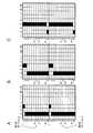
図6は、マルチディスプレイ装置で表示される画像の例を示す模式図である。画像は、第1及び第2のディスプレイが夫々に表示する画像からなり、各ディスプレイが表示する画像は、N×M個の画素からなっている。図6Aは、マルチディスプレイ装置で縦の直線が横方向へ移動する動画を表示する際の一つのフレームの画像である。図6Aに示す画像は、縦の直線からなる。図6Bは、図6Aに示す画像の次のフレームの画像である。図6Bでは、図6Aに比べて、直線を表示している画素の位置が異なっている。動画を表示する際には、図6Aに示す画像が、図6Bに示す画像へ切り替わることになる。 FIG. 6 is a schematic diagram illustrating an example of an image displayed on the multi-display device. The image is composed of images displayed on the first and second displays, respectively, and the image displayed on each display is composed of N × M pixels. FIG. 6A is an image of one frame when displaying a moving image in which a vertical straight line moves in the horizontal direction on the multi-display device. The image shown in FIG. 6A is composed of vertical straight lines. FIG. 6B is an image of the next frame of the image shown in FIG. 6A. In FIG. 6B, the position of the pixel displaying the straight line is different from that in FIG. 6A. When the moving image is displayed, the image shown in FIG. 6A is switched to the image shown in FIG. 6B.
図7は、従来のマルチディスプレイ装置において画像が切り替わる際に各画素の表示状態が変化する様子を示す模式図である。図7Aは、最初の画素ラインが変化した状態を示す。画像の表示時には第1画素ラインから第N画素ラインまで順次的に表示されるので、最初に第1画素ラインが変化する。即ち、第1画素ライン上で直線を表示している画素の位置が変化する一方で、他の画素ライン上では直線を表示している画素の位置は変化していない。第1及び第2のディスプレイの境界部分では、第1のディスプレイが表示する第N画素ラインと第2のディスプレイが表示する第1画素ラインとの間で、直線を表示している画素の位置がずれている。図7Bは、二番目に画素ラインが変化した状態を示す。第1画素ラインに続いて、第2画素ラインが変化する。同様にして、順次的に各画素ラインが変化していく。図7Cは、第N−1番目に画素ラインが変化した状態を示す。第1画素ラインから第(N−1)画素ラインまで、画素ライン上で直線を表示している画素の位置が変化しており、第N画素ライン上では未だ直線を表示している画素の位置は変化していない。この状態でも、第1のディスプレイが表示する第N画素ラインと第2のディスプレイが表示する第1画素ラインとの間で、直線を表示している画素の位置がずれている。最後に、第N画素ラインが変化し、図6Bに示すごとく画像が切り替わる。 FIG. 7 is a schematic diagram showing how the display state of each pixel changes when an image is switched in a conventional multi-display device. FIG. 7A shows a state in which the first pixel line has changed. Since an image is sequentially displayed from the first pixel line to the Nth pixel line when an image is displayed, the first pixel line is changed first. That is, the position of the pixel displaying the straight line on the first pixel line changes, while the position of the pixel displaying the straight line on the other pixel lines does not change. At the boundary between the first and second displays, the position of the pixel displaying a straight line is between the Nth pixel line displayed on the first display and the first pixel line displayed on the second display. It is off. FIG. 7B shows a state where the pixel line has changed second. Following the first pixel line, the second pixel line changes. Similarly, each pixel line changes sequentially. FIG. 7C shows a state in which the pixel line has changed in the (N-1) th. From the first pixel line to the (N−1) th pixel line, the position of the pixel displaying a straight line on the pixel line has changed, and the position of the pixel still displaying a straight line on the Nth pixel line Has not changed. Even in this state, the position of the pixel displaying the straight line is shifted between the Nth pixel line displayed on the first display and the first pixel line displayed on the second display. Finally, the Nth pixel line changes, and the images are switched as shown in FIG. 6B.
図7に示すように、従来のマルチディスプレイ装置では、画像が切り替わる際、第1のディスプレイが表示する第N画素ラインと第2のディスプレイが表示する第1画素ラインとの間で、画像を表示している画素の位置が長時間ずれている。この画素の位置のずれは、長時間発生しているので、人の目に認識可能な画像の乱れが発生することになる。従って、従来のマルチディスプレイ装置で動画を表示する場合には、ディスプレイの境界部分で画像のずれが発生する。 As shown in FIG. 7, in the conventional multi-display device, when an image is switched, an image is displayed between the Nth pixel line displayed on the first display and the first pixel line displayed on the second display. The position of the current pixel is shifted for a long time. Since the displacement of the pixel position occurs for a long time, an image disturbance that can be recognized by human eyes occurs. Accordingly, when a moving image is displayed on a conventional multi-display device, an image shift occurs at the boundary portion of the display.
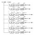
本実施形態に係るマルチディスプレイ装置では、各ディスプレイが画素ラインを表示する順番を従来と異ならせることによって、近接する画素ライン間で画像を表示している画素の位置が長時間ずれることを防止する。図8は、実施形態1に係るゲートドライバ12の構成を示すブロック図である。ゲートドライバ12の各構成部分は、電源部18から電力を供給されて動作する。タイミングコントローラ15から、各シフトレジスタへクロック信号が入力され、第1のシフトレジスタ41へトリガ信号が入力され、第2のシフトレジスタ42から第Nのシフトレジスタ4Nまで、順次的にトリガ信号が入力されるようになっている。シフトレジスタ41は、第Hのレベルシフタ5Hに接続されている。このため、シフトレジスタ41は、レベルシフタ5Hへ信号を入力し、レベルシフタ5Hは信号を第Hの供給部6Hへ入力し、供給部6Hは第Hのゲート線33Hへ信号を供給する。従って、本実施形態に係るディスプレイ1では、N個のゲート線の内でゲート線33Hに最初に信号が供給され、N個の画素ラインの内で第H画素ラインが最初に表示される。 In the multi-display device according to this embodiment, the display order of the pixel lines on each display is different from the conventional order, thereby preventing the position of the pixel displaying the image from shifting between adjacent pixel lines for a long time. . FIG. 8 is a block diagram illustrating a configuration of the
第2のシフトレジスタ42は、第(H+1)のレベルシフタ5(H+1)に接続されている。このため、シフトレジスタ42は、レベルシフタ5(H+1)へ信号を入力し、最終的に第(H+1)のゲート線33(H+1)へ信号が供給される。第3のシフトレジスタ43は、第(H−1)のレベルシフタ5(H−1)に接続されている。このため、シフトレジスタ43は、レベルシフタ5(H−1)へ信号を入力し、最終的に第(H−1)のゲート線33(H−1)へ信号が供給される。図示していないものの、第4のシフトレジスタは第(H+2)のレベルシフタに接続され、第5のシフトレジスタは第(H−2)のレベルシフタに接続されている。第(N−1)のシフトレジスタ4(N−1)は第1のレベルシフタ51に接続され、第Nのシフトレジスタ4Nは第Nのレベルシフタ5Nに接続されている。このため、最後から二番目に第1のゲート線331に信号が供給され、最後に第Nのゲート線33Nに信号が供給される。このように、ゲートドライバ12は、平行に配線されたN本のゲート線の内、両端の中間にあるゲート線33Hへ最初に信号を供給し、一端のゲート線3Nに近い側のゲート線と他端のゲート線331に近い側のゲート線とへ交互に信号を供給しながら、ゲート線33Hからゲート線331及びゲート線33Nに向けて順次的に各ゲート線へ信号を供給するようになっている。以上のような順番で各ゲート線に信号が供給され、各画素ラインが表示され、ディスプレイ1に画像が表示される。 The
図9は、実施形態1に係るマルチディスプレイ装置において各ゲート線へ信号を供給するタイミングを模式的に示すタイミングチャートである。縦に並んだ第1及び第2のディスプレイ1における各ゲート線への信号の供給タイミングを示している。図中の横軸は時間であり、ゲート線に信号が供給されている状態を縦軸のハイで示している。第H画素ラインに対応するゲート線33Hに最初に信号が供給され、ゲート線33Nに近い側のゲート線とゲート線331に近い側のゲート線とへ交互に信号が供給されながら、ゲート線331及びゲート線33Nに向けて順次的に各ゲート線に信号が供給される。ディスプレイ1は、各ゲート線に対応する画素ラインを順次的に表示する。ゲート線331とゲート線33Nとは、信号が供給されるタイミングが非常に近くなっている。このため、第1のディスプレイ1が表示する第N画素ラインと第2のディスプレイ1が表示する第1画素ライン1との間では、表示される際の時間差が非常に小さくなっている。 FIG. 9 is a timing chart schematically showing the timing of supplying signals to the gate lines in the multi-display device according to the first embodiment. The signal supply timing to each gate line in the first and
図10は、実施形態1に係るマルチディスプレイ装置において画像が切り替わる際に各画素の表示状態が変化する様子を示す模式図である。図10には、図6に示すように縦の直線からなる画像が切り替わる際の表示状態を示す。図10Aは、図6Aに示す状態から最初の画素ラインが変化した状態を示す。最初に第H画素ラインが変化する。第H画素ライン上で直線を表示している画素の位置が変化する一方で、他の画素ライン上では直線を表示している画素の位置は変化していない。第1及び第2のディスプレイ1の境界部分では、第1のディスプレイ1が表示する第N画素ラインと第2のディスプレイ1が表示する第1画素ラインとの間では、直線を表示している画素の位置はずれていない。図10Bは、二番目に画素ラインが変化した状態を示す。第H画素ラインに続いて、第(H+1)画素ラインが変化する。図10Cは、三番目に画素ラインが変化した状態を示す。ひき続いて、第(H−1)画素ラインが変化する。同様にして、第N画素ラインに近い側の画素ラインと第1画素ラインに近い側の画素ラインとが交互に変化しながら、第1画素ライン及び第N画素ラインに向けて順次的に各画素ラインが変化していく。 FIG. 10 is a schematic diagram illustrating a state in which the display state of each pixel changes when an image is switched in the multi-display apparatus according to the first embodiment. FIG. 10 shows a display state when an image composed of vertical straight lines is switched as shown in FIG. FIG. 10A shows a state in which the first pixel line has changed from the state shown in FIG. 6A. First, the Hth pixel line changes. While the position of the pixel displaying a straight line on the Hth pixel line changes, the position of the pixel displaying a straight line does not change on the other pixel lines. Pixels displaying a straight line between the Nth pixel line displayed on the
図10Dは、第N−2番目に画素ラインが変化した状態を示す。第2画素ラインから第(N−1)画素ラインまで、画素ライン上で直線を表示している画素の位置が変化している。この状態でも、第1のディスプレイ1が表示する第N画素ラインと第2のディスプレイ1が表示する第1画素ラインとの間では、直線を表示している画素の位置はずれていない。図10Eは、第N−1番目に画素ラインが変化した状態を示す。第1画素ライン上で直線を表示している画素の位置が変化し、第1のディスプレイ1が表示する第N画素ラインと第2のディスプレイ1が表示する第1画素ラインとの間で、直線を表示している画素の位置がずれる。次に、図6Bに示したように、第N画素ライン上で直線を表示している画素の位置が変化し、第1のディスプレイ1が表示する第N画素ラインと第2のディスプレイ1が表示する第1画素ラインとの間での画素の位置のずれは解消される。 FIG. 10D shows a state in which the pixel line has changed in the (N−2) th. From the second pixel line to the (N−1) th pixel line, the position of the pixel displaying a straight line on the pixel line is changed. Even in this state, the position of the pixel displaying the straight line is not shifted between the Nth pixel line displayed on the
図10に示すように、第1のディスプレイ1が表示する第N画素ラインと第2のディスプレイ1が表示する第1画素ラインとは、近接しているものの、画像が切り替わる際、画像を表示している画素の位置のずれは非常に短時間で解消される。また、他の隣接する画素ラインの間においても、画像を表示している画素の位置のずれは非常に短時間で解消される。従って、近接する画素ライン間で画像を表示している画素の位置が長時間ずれることが防止される。 As shown in FIG. 10, although the Nth pixel line displayed on the
以上詳述したごとく、本実施形態に係るマルチディスプレイ装置は、各ディスプレイ1において、複数の画素ラインが縦方向に並んでなる画像を表示する際に、N個の画素ラインの内、略中央に位置する第H画素ラインを最初に表示し、第N画素ラインに近い側の画素ラインと第1画素ラインに近い側の画素ラインとを交互に表示しながら、第1画素ライン及び第N画素ラインに向けて順次的に各画素ラインを表示する。このように、各画素ラインを表示する順番を従来と異ならせることにより、ディスプレイ1が第1画素ラインと第N画素ラインとを表示する時点の間の時間差が非常に小さくなる。縦に並んだ二つのディスプレイ1の境界部分では、一方のディスプレイ1の第N画素ラインと他方のディスプレイ1の第1画素ラインとが近接しているものの、第1画素ラインと第N画素ラインとが表示される時点間の時間差が小さいので、人の目に認識可能な画像の乱れは発生しない。また、動画を表示する場合等、マルチディスプレイ装置で表示する画像を切り替える場合、ディスプレイ1の境界部分で近接する画素ライン間で画像を表示している画素の位置が長時間ずれることが防止される。このため、画像を表示している画素の位置のずれは使用者には認識されない。従って、本実施形態に係るマルチディスプレイ装置は、乱れの無い画像を表示することが可能であり、動画を表示する際にも、画像のずれの発生を防止することが可能である。 As described above in detail, the multi-display device according to the present embodiment displays the image in which the plurality of pixel lines are arranged in the vertical direction on each
(実施形態2)
図11は、実施形態2に係るゲートドライバ12の構成を示すブロック図である。マルチディスプレイ装置のゲートドライバ12以外の構成は、実施形態1と同様である。タイミングコントローラ15から、第Hのシフトレジスタ4Hへトリガ信号が入力され、シフトレジスタ4Hは、第Hのレベルシフタ5Hへ信号を入力し、レベルシフタ5Hは信号を第Hの供給部6Hへ入力し、供給部6Hは第Hのゲート線33Hへ信号を供給する。従って、本実施形態に係るディスプレイ1でも、N個のゲート線の内でゲート線33Hに最初に信号が供給され、N個の画素ラインの内で第H画素ラインが最初に表示される。(Embodiment 2)
FIG. 11 is a block diagram illustrating a configuration of the
シフトレジスタ4Hは、第(H+1)のシフトレジスタ4(H+1)に接続されており、トリガ信号をシフトレジスタ4(H+1)へ入力するようになっている。シフトレジスタ4(H+1)は第(H+1)のレベルシフタ5(H+1)へ信号を入力し、最終的に第(H+1)のゲート線33(H+1)へ信号が供給される。シフトレジスタ4(H+1)は、第(H−1)のシフトレジスタ4(H−1)に接続されており、トリガ信号をシフトレジスタ4(H−1)へ入力するようになっている。このように、複数のシフトレジスタは、シフトレジスタ4Hから、第Nのシフトレジスタ3Nに近い側のシフトレジスタと第1のシフトレジスタ41に近い側のシフトレジスタとへ交互にトリガ信号を入力しながら、シフトレジスタ41及びシフトレジスタ3Nに向けて順次的にトリガ信号を入力するように互いに接続されている。第2のシフトレジスタ42は第(N−1)のシフトレジスタ4(N−1)へトリガ信号を入力し、シフトレジスタ4(N−1)は第1のシフトレジスタ41へトリガ信号を入力し、シフトレジスタ41は第Nのシフトレジスタ4Nへトリガ信号を入力する。 The
シフトレジスタが以上のように接続されていることによって、本実施形態においても、最初にゲート線33Hへ信号が供給され、ゲート線331及びゲート線33Nに向けて、第Nのゲート線33Nに近い側のゲート線と第1のゲート線331に近い側のゲート線とへ交互に信号が供給されながら、順次的に各ゲート線に信号が供給される。従って、本実施形態においても、実施形態1と同様に、ディスプレイ1は、複数の画素ラインが縦方向に並んでなる画像を表示する際に、N個の画素ラインの内、略中央に位置する第H画素ラインを最初に表示し、第N画素ラインに近い側の画素ラインと第1画素ラインに近い側の画素ラインとを交互に表示しながら、第1画素ライン及び第N画素ラインに向けて順次的に各画素ラインを表示する。 Since the shift registers are connected as described above, also in the present embodiment, a signal is first supplied to the
本実施形態においても、ディスプレイ1が第1画素ラインと第N画素ラインとを表示する時点間の時間差が非常に小さくなり、縦に並んだ二つのディスプレイ1の境界部分では、画像の乱れは発生しない。また、マルチディスプレイ装置で表示する画像を切り替える場合、近接する画素ライン間で画像を表示している画素の位置が長時間ずれることが防止される。従って、本実施形態においても、マルチディスプレイ装置は、乱れの無い画像を表示することが可能であり、動画を表示する際にも、画像のずれの発生を防止することが可能である。 Also in the present embodiment, the time difference between the time points when the
なお、実施形態1及び2におけるゲートドライバ12の構成は例であり、画素ラインの表示される順番が実施形態1及び2で示した順番になる限り、ゲートドライバ12の構成はその他の構成であってもよい。例えば、ゲートドライバ12は、複数のレベルシフタと複数の供給部との間の配線が従来と異なっている形態であってもよい。 Note that the configuration of the
(実施形態3)
図12は、実施形態3に係るゲートドライバ12の構成を示すブロック図である。マルチディスプレイ装置のゲートドライバ12以外の構成は、実施形態1と同様である。タイミングコントローラ15から、各シフトレジスタへクロック信号が入力され、第1のシフトレジスタ41へトリガ信号が入力され、第2のシフトレジスタ42から第Nのシフトレジスタ4Nまで、順次的にトリガ信号が入力されるようになっている。シフトレジスタ41は、第1のレベルシフタ51へ信号を入力し、レベルシフタ51は信号を供給部61へ入力し、供給部61は第1のゲート線331へ信号を供給する。従って、本実施形態に係るディスプレイ1では、ゲート線331に最初に信号が供給され、N個の画素ラインの内で第1画素ラインが最初に表示される。(Embodiment 3)
FIG. 12 is a block diagram illustrating a configuration of the
第2のシフトレジスタ42は、第Nのレベルシフタ5Nに接続されている。このため、シフトレジスタ42は、レベルシフタ5Nへ信号を入力し、最終的に第Nのゲート線33Nへ信号が供給される。第3のシフトレジスタ43は、第2のレベルシフタ52に接続されている。このため、シフトレジスタ43は、レベルシフタ52へ信号を入力し、最終的に第2のゲート線332へ信号が供給される。図示していないものの、第4のシフトレジスタは第(N−1)のレベルシフタ5(N−1)に接続されている。また、第(N−1)のシフトレジスタ4(N−1)は第Hのレベルシフタ5Hに接続され、第Nのシフトレジスタ4Nは第(H+1)のレベルシフタ5(H+1)に接続されている。このため、最後から二番目にゲート線33Hに信号が供給され、最後にゲート線33(H+1)に信号が供給される。このように、ゲートドライバ12は、平行に配線されたN本のゲート線の内、一端にあるゲート線331へ最初に信号を供給し、他端にあるゲート線33Nへ次に信号を供給し、ゲート線331及びゲート線33Nから中央側のゲート線に向けて、一端のゲート線331に近い側のゲート線と他端のゲート線33Nに近い側のゲート線とへ交互に信号を供給しながら、各ゲート線へ信号を供給するようになっている。以上のような順番で各ゲート線に信号が供給され、各画素ラインが表示され、ディスプレイ1に画像が表示される。 The
図13は、実施形態3に係るマルチディスプレイ装置において各ゲート線へ信号を供給するタイミングを模式的に示すタイミングチャートである。縦に並んだ第1及び第2のディスプレイ1における各ゲート線への信号の供給タイミングを示している。図中の横軸は時間であり、ゲート線に信号が供給されている状態を縦軸のハイで示している。第1画素ラインに対応するゲート線331に最初に信号が供給され、第N画素ラインに対応するゲート線33Nに次に信号が供給され、ゲート線331に近い側のゲート線とゲート線33Nに近い側のゲート線とへ交互に信号が供給されながら、中央側のゲート線に向けて順次的に各ゲート線に信号が供給される。ディスプレイ1は、各ゲート線に対応する画素ラインを順次的に表示する。本実施形態においても、ゲート線331とゲート線33Nとは、信号が供給されるタイミングが非常に近くなっている。このため、第1のディスプレイ1が表示する第N画素ラインと第2のディスプレイ1が表示する第1画素ライン1とが表示される時点の間の時間差は、非常に小さくなっている。 FIG. 13 is a timing chart schematically showing the timing of supplying signals to the gate lines in the multi-display device according to the third embodiment. The signal supply timing to each gate line in the first and
図14は、実施形態3に係るマルチディスプレイ装置において画像が切り替わる際に各画素の表示状態が変化する様子を示す模式図である。図14Aは、図6Aに示す状態から最初の画素ラインが変化した状態を示す。最初に第1画素ラインが変化する。第1画素ライン上で直線を表示している画素の位置が変化する一方で、他の画素ライン上では直線を表示している画素の位置は変化していない。第1及び第2のディスプレイ1の境界部分では、第1のディスプレイ1が表示する第N画素ラインと第2のディスプレイ1が表示する第1画素ラインとの間で、直線を表示している画素の位置がずれている。図14Bは、二番目に画素ラインが変化した状態を示す。第1画素ラインに続いて、第N画素ラインが変化する。この時点で、第1のディスプレイ1が表示する第N画素ラインと第2のディスプレイ1が表示する第1画素ラインとの間での画素の位置のずれは解消される。 FIG. 14 is a schematic diagram illustrating how the display state of each pixel changes when an image is switched in the multi-display apparatus according to the third embodiment. FIG. 14A shows a state in which the first pixel line has changed from the state shown in FIG. 6A. First, the first pixel line changes. While the position of the pixel displaying the straight line on the first pixel line changes, the position of the pixel displaying the straight line on the other pixel line does not change. Pixels displaying a straight line between the Nth pixel line displayed on the
図14Cは、三番目に画素ラインが変化した状態を示す。ひき続いて、第2画素ラインが変化する。同様にして、第1画素ライン及び第N画素ラインから中央側の画素ラインに向けて、第1画素ラインに近い側の画素ラインと第N画素ラインに近い側の画素ラインとが交互に変化しながら、順次的に各画素ラインが変化していく。図14Dは、第N−2番目に画素ラインが変化した状態を示す。第1画素ラインから第(H−1)画素ラインまで、更に第(H+2)画素ラインから第N画素ラインまで、画素ライン上で直線を表示している画素の位置が変化している。図14Eは、第N−1番目に画素ラインが変化した状態を示す。第H画素ラインが変化する。次に、図6Bに示したように、第(H+1)画素ラインが変化し、画像の切り替えが終了する。 FIG. 14C shows a state where the pixel line is changed third. Subsequently, the second pixel line changes. Similarly, a pixel line closer to the first pixel line and a pixel line closer to the Nth pixel line alternately change from the first pixel line and the Nth pixel line toward the central pixel line. However, each pixel line changes sequentially. FIG. 14D shows a state in which the pixel line has changed in the (N−2) th. From the first pixel line to the (H-1) pixel line, and further from the (H + 2) pixel line to the Nth pixel line, the position of the pixel displaying a straight line on the pixel line is changed. FIG. 14E shows a state where the pixel line has changed in the (N-1) th. The Hth pixel line changes. Next, as shown in FIG. 6B, the (H + 1) th pixel line changes, and the image switching is completed.
図14に示すように、第1のディスプレイ1が表示する第N画素ラインと第2のディスプレイ1が表示する第1画素ラインとは、近接しているものの、画像が切り替わる際、画像を表示している画素の位置のずれは非常に短時間で解消される。また、他の隣接する画素ラインの間においても、画像を表示している画素の位置のずれは非常に短時間で解消される。従って、近接する画素ライン間で画像を表示している画素の位置が長時間ずれることが防止される。 As shown in FIG. 14, although the Nth pixel line displayed on the
以上詳述したごとく、本実施形態に係るマルチディスプレイ装置は、各ディスプレイ1において、最初に第1画素ラインを表示し、次に第N画素ラインを表示し、第1画素ライン及び第N画素ラインから中央側の画素ラインに向けて、第1画素ラインに近い側の画素ラインと第N画素ラインに近い側の画素ラインとを交互に表示しながら、順次的に各画素ラインを表示する。このように、本実施形態でも、各画素ラインを表示する順番が従来と異なっており、ディスプレイ1が第1画素ラインと第N画素ラインとを表示する時点の間の時間差が非常に小さい。このため、縦に並んだ二つのディスプレイ1の境界部分では、一方のディスプレイ1の第N画素ラインと他方のディスプレイ1の第1画素ラインとが近接しているものの、画像の乱れは発生しない。また、動画を表示する場合等、マルチディスプレイ装置で表示する画像を切り替える場合、ディスプレイ1の境界部分で近接する画素ライン間で画像を表示している画素の位置が長時間ずれることが防止される。従って、本実施形態においても、マルチディスプレイ装置は、乱れの無い画像を表示することが可能であり、動画を表示する際にも、画像のずれの発生を防止することが可能である。 As described above in detail, the multi-display device according to the present embodiment first displays the first pixel line, then displays the Nth pixel line on each
なお、実施形態3におけるゲートドライバ12の構成は一例であり、画素ラインの表示される順番が実施形態3で示した順番になる限り、ゲートドライバ12の構成はその他の構成であってもよい。例えば、ゲートドライバ12は、複数のシフトレジスタの相互の接続が従来と異なっている形態であってもよく、複数のレベルシフタと複数の供給部との間の配線が従来と異なっている形態であってもよい。 The configuration of the
以上の実施形態1〜3においては、画素ライン及びゲート線の数Nが偶数である例を示したが、Nは奇数であってもよい。Nが奇数である場合は、(N+1)/2=Hである。また、実施形態1〜3で示した第1画素ラインに近い側の画素ラインと第N画素ラインに近い側の画素ラインとを交互に表示する順番は、一例であり、マルチディスプレイ装置は、逆の順番で画素ラインを表示する形態であってもよい。例えば、実施形態1及び2では、最初に第H画素ラインを表示し、次に第(H+1)画素ラインを表示し、次に第(H−1)画素ラインを表示する例を示したが、マルチディスプレイ装置は、第H画素ラインの次に第(H−1)画素ラインを表示し、次に第(H+1)画素ラインを表示する順番で各画素ラインを表示してもよい。また例えば、実施形態3では、最初に第1画素ラインを表示し、次に第N画素ラインを表示する例を示したが、マルチディスプレイ装置は、最初に第N画素ラインを表示し、次に第1画素ラインを表示する順番で各画素ラインを表示してもよい。また、実施形態1〜3においては、第1画素ラインに近い側の画素ラインと第N画素ラインに近い側の画素ラインとを交互に表示する順番を全てのディスプレイ1で同一にした例を示したが、マルチディスプレイ装置は、上下に隣接したディスプレイ1の間で各画素ラインを表示する順番を逆にしてもよい。例えば、第1のディスプレイ1で最初に第1画素ラインを表示し次に第N画素ラインを表示する順番で各画素ラインを表示し、第2のディスプレイ1で最初に第N画素ラインを表示し次に第1画素ラインを表示する順番で各画素ラインを表示してもよい。この場合は、第1のディスプレイ1の第N画素ラインと第2のディスプレイ1の第1画素ラインとが表示される時点間の時間差がより小さくなり、画像のずれの発生がより軽減される。 In the above first to third embodiments, an example in which the number N of pixel lines and gate lines is an even number is shown, but N may be an odd number. When N is an odd number, (N + 1) / 2 = H. The order of alternately displaying the pixel lines closer to the first pixel line and the pixel lines closer to the Nth pixel line shown in the first to third embodiments is an example, and the multi-display device is reversed. The pixel lines may be displayed in this order. For example, in the first and second embodiments, the H-th pixel line is displayed first, then the (H + 1) -th pixel line is displayed, and then the (H-1) -th pixel line is displayed. The multi-display device may display each pixel line in the order of displaying the (H−1) th pixel line next to the Hth pixel line and then displaying the (H + 1) th pixel line. For example, in the third embodiment, the first pixel line is displayed first, and then the Nth pixel line is displayed. However, the multi-display apparatus first displays the Nth pixel line, and then displays the Nth pixel line. You may display each pixel line in the order which displays a 1st pixel line. In the first to third embodiments, an example is shown in which the order in which the pixel lines closer to the first pixel line and the pixel lines closer to the Nth pixel line are alternately displayed is the same in all the
また、実施形態1〜3では、ゲートドライバ12の構成を従来と異ならせた形態を示したが、マルチディスプレイ装置は、ゲートドライバ12の構成を変更する方法とは異なる方法で、画素ラインを表示する順番を従来と異ならせた形態であってもよい。また、実施形態1〜3では、液晶パネル11を用いて画像を表示する形態を示したが、マルチディスプレイ装置は、複数の画素ラインを順次的に表示することによって画像を表示するディスプレイであれば、液晶パネルを用いたディスプレイとは異なるディスプレイを備えた形態であってもよい。 Further, in the first to third embodiments, the configuration in which the configuration of the
以上のように、本発明に係るマルチディスプレイ装置は、夫々に複数の画素が横方向に並んだ複数の画素ラインが縦方向に並んでなる画像を夫々に表示する複数のディスプレイ(1)を少なくとも縦方向に配列してあり、各ディスプレイ(1)は画像の表示時に各画素ラインを順次的に表示するマルチディスプレイ装置において、各ディスプレイ(1)は、画像を表示する際に複数の画素ラインの夫々を順次的に表示する順番を、一端の画素ラインを最初に表示して他端の画素ラインを最後に表示する順番とは異なる順番にしてあることを特徴とする。 As described above, the multi-display device according to the present invention includes at least a plurality of displays (1) each displaying an image in which a plurality of pixel lines each having a plurality of pixels arranged in the horizontal direction are arranged in the vertical direction. In a multi-display device that is arranged in the vertical direction and each display (1) sequentially displays each pixel line when displaying an image, each display (1) has a plurality of pixel lines when displaying an image. The order in which each is sequentially displayed is different from the order in which the pixel line at one end is displayed first and the pixel line at the other end is displayed last.
本発明に係るマルチディスプレイ装置は、各ディスプレイ(1)は、画像の表示時に、前記複数の画素ラインの内、両端の画素ラインを除く特定の画素ラインを最初に表示し、前記特定の画素ラインから両端の画素ラインに向けて順次的に各画素ラインを表示するように構成してあることを特徴とする。 In the multi-display device according to the present invention, each display (1) first displays a specific pixel line excluding the pixel lines at both ends of the plurality of pixel lines at the time of displaying an image. Each pixel line is displayed sequentially from the pixel toward the pixel lines at both ends.
本発明に係るマルチディスプレイ装置は、各ディスプレイ(1)は、画像に含まれる各画素を表示するための複数の素子(31、32)がマトリクス状に配列されており、各画素ラインに対応する複数の素子(31、32)に夫々接続された複数の信号線(331〜33N)を含む回路(110)と、前記複数の信号線(331〜33N)の夫々へ前記複数の素子(31、32)を動作させるための信号を供給するドライバ(12)とを備え、前記ドライバ(12)は、画像の表示時に、前記特定の画素ラインに対応する複数の素子(31、32)に接続された信号線(33H)へ最初に信号を供給し、両端の画素ラインに対応する複数の素子(31、32)に接続された信号線(331、33N)に向けて順次的に各信号線へ信号を供給するように構成してあることを特徴とする。 In the multi-display device according to the present invention, each display (1) has a plurality of elements (31, 32) for displaying each pixel included in an image arranged in a matrix and corresponds to each pixel line. A circuit (110) including a plurality of signal lines (331 to 33N) respectively connected to the plurality of elements (31, 32) and the plurality of elements (31, 31) to each of the plurality of signal lines (331 to 33N). And a driver (12) for supplying a signal for operating 32), and the driver (12) is connected to a plurality of elements (31, 32) corresponding to the specific pixel line when displaying an image. First, a signal is supplied to the signal line (33H) and sequentially supplied to each signal line toward the signal lines (331, 33N) connected to the plurality of elements (31, 32) corresponding to the pixel lines at both ends. Supply signal Characterized in that are configured to.
本発明に係るマルチディスプレイ装置は、各ディスプレイ(1)は、画像の表示時に、前記複数の画素ラインの内、一端の画素ラインを最初に表示し、他端の画素ラインを次に表示し、両端の画素ラインから中央側の画素ラインに向けて、前記一端に近い画素ラインと前記他端に近い画素ラインとを交互に表示しながら、順次的に各画素ラインを表示するように構成してあることを特徴とする。 In the multi-display device according to the present invention, each display (1) first displays a pixel line at one end of the plurality of pixel lines and then displays a pixel line at the other end when displaying an image. From the pixel lines at both ends toward the pixel line on the center side, the pixel lines close to the one end and the pixel lines close to the other end are alternately displayed, and each pixel line is sequentially displayed. It is characterized by being.
本発明に係るマルチディスプレイ装置は、各ディスプレイ(1)は、画像に含まれる各画素を表示するための複数の素子(31、32)がマトリクス状に配列されており、各画素ラインに対応する複数の素子(31、32)に夫々接続された複数の信号線(331〜33N)を含む回路(110)と、前記複数の信号線(331〜33N)の夫々へ前記複数の素子(31、32)を動作させるための信号を供給するドライバ(12)とを備え、前記ドライバ(12)は、画像の表示時に、前記一端の画素ラインに対応する複数の素子(31、32)に接続された信号線(331)へ最初に信号を供給し、前記他端の画素ラインに対応する複数の素子(31、32)に接続された信号線(33N)へ次に信号を供給し、両端の画素ラインに対応する複数の素子(31、32)に接続された信号線(331、33N)から中央側の画素ラインに対応する複数の素子(31、32)に接続された信号線に向けて、前記一端に近い画素ラインに対応する複数の素子(31、32)に接続された信号線と前記他端に近い画素ラインに対応する複数の素子(31、32)に接続された信号線とへ交互に信号を供給しながら、順次的に各信号線へ信号を供給するように構成してあることを特徴とする。 In the multi-display device according to the present invention, each display (1) has a plurality of elements (31, 32) for displaying each pixel included in an image arranged in a matrix and corresponds to each pixel line. A circuit (110) including a plurality of signal lines (331 to 33N) respectively connected to the plurality of elements (31, 32) and the plurality of elements (31, 31) to each of the plurality of signal lines (331 to 33N). And a driver (12) for supplying a signal for operating 32), and the driver (12) is connected to a plurality of elements (31, 32) corresponding to the pixel line at the one end when displaying an image. The first signal is supplied to the signal line (331), the signal is next supplied to the signal line (33N) connected to the plurality of elements (31, 32) corresponding to the pixel line at the other end, Compatible with pixel lines From the signal line (331, 33N) connected to the plurality of elements (31, 32) to the signal line connected to the plurality of elements (31, 32) corresponding to the central pixel line, Signals are alternately transmitted to the signal lines connected to the plurality of elements (31, 32) corresponding to the near pixel line and the signal lines connected to the plurality of elements (31, 32) corresponding to the pixel line near the other end. It is characterized in that the signal is sequentially supplied to each signal line while supplying the signal.
本発明に係るディスプレイ(1)は、夫々に複数の画素が横方向に並んだ複数の画素ラインが縦方向に並んでなる画像を表示するために、各画素ラインを順次的に表示するディスプレイ(1)において、複数の画素ラインの夫々を順次的に表示する順番を、一端の画素ラインを最初に表示して他端の画素ラインを最後に表示する順番とは異なる順番にしてあることを特徴とする。 The display (1) according to the present invention is a display that sequentially displays each pixel line in order to display an image in which a plurality of pixel lines each having a plurality of pixels arranged in the horizontal direction are arranged in the vertical direction. In 1), the order in which each of the plurality of pixel lines is sequentially displayed is different from the order in which the pixel line at one end is displayed first and the pixel line at the other end is displayed last. And
本発明に係る画像表示方法は、夫々に複数の画素が横方向に並んだ複数の画素ラインが縦方向に並んでなる画像を夫々に表示する複数のディスプレイ(1)を少なくとも縦方向に配列してあり、各ディスプレイ(1)は画像の表示時に各画素ラインを順次的に表示するマルチディスプレイ装置で、画像を表示する方法において、各ディスプレイ(1)は、前記複数の画素ラインの内、両端の画素ラインを除く特定の画素ラインを最初に表示し、前記特定の画素ラインから両端の画素ラインに向けて順次的に各画素ラインを表示することを特徴とする。 In the image display method according to the present invention, a plurality of displays (1) each displaying an image in which a plurality of pixel lines each having a plurality of pixels arranged in the horizontal direction are arranged in the vertical direction are arranged at least in the vertical direction. Each display (1) is a multi-display device that sequentially displays each pixel line when displaying an image. In the method of displaying an image, each display (1) has both ends of the plurality of pixel lines. Specific pixel lines other than the pixel line are displayed first, and each pixel line is sequentially displayed from the specific pixel line toward the pixel lines at both ends.
本発明に係る画像表示方法は、夫々に複数の画素が横方向に並んだ複数の画素ラインが縦方向に並んでなる画像を夫々に表示する複数のディスプレイ(1)を少なくとも縦方向に配列してあり、各ディスプレイ(1)は画像の表示時に各画素ラインを順次的に表示するマルチディスプレイ装置で、画像を表示する方法において、各ディスプレイ(1)は、前記複数の画素ラインの内、一端の画素ラインを最初に表示し、他端の画素ラインを次に表示し、両端の画素ラインから中央側の画素ラインに向けて、前記一端に近い画素ラインと前記他端に近い画素ラインとを交互に表示しながら、順次的に各画素ラインを表示することを特徴とする。 In the image display method according to the present invention, a plurality of displays (1) each displaying an image in which a plurality of pixel lines each having a plurality of pixels arranged in the horizontal direction are arranged in the vertical direction are arranged at least in the vertical direction. Each display (1) is a multi-display device that sequentially displays each pixel line when displaying an image. In the method for displaying an image, each display (1) is one end of the plurality of pixel lines. The first pixel line, the second pixel line next, and the pixel lines near the one end and the pixel lines near the other end from the pixel lines at both ends toward the central pixel line. Each pixel line is sequentially displayed while being alternately displayed.
本発明においては、マルチディスプレイ装置は、複数の画素ラインが縦方向に並んでなる画像を表示する複数のディスプレイ(1)を少なくとも縦方向に配列してある。各ディスプレイ(1)は、複数の画素ラインの夫々表示する順番を、最初に一端の画素ラインを表示して最後に他端の画素ラインを表示する順番とは異なる順番にする。これにより、両端の画素ラインを表示する時点の間の時間差が小さくなる。縦に並んだ二つのディスプレイ(1)の境界部分では、両端の画素ラインが近接しているものの、両端の画素ラインを表示する時点間の時間差が小さいので、画像の乱れは発生しない。特に、マルチディスプレイ装置で動画を表示する際に、二つのディスプレイ(1)の境界部分で画像のずれが発生しない。 In the present invention, in the multi-display device, a plurality of displays (1) for displaying an image in which a plurality of pixel lines are arranged in the vertical direction are arranged at least in the vertical direction. In each display (1), the display order of each of the plurality of pixel lines is set to an order different from the order in which the pixel line at one end is displayed first and the pixel line at the other end is finally displayed. Thereby, the time difference between the time points when the pixel lines at both ends are displayed becomes small. Although the pixel lines at both ends are close to each other at the boundary portion between the two displays (1) arranged vertically, the time difference between the time points when the pixel lines at both ends are displayed is small, so that the image is not disturbed. In particular, when displaying a moving image on a multi-display device, no image shift occurs at the boundary between the two displays (1).
本発明においては、マルチディスプレイ装置は、各ディスプレイ(1)において、複数の画素ラインの内、両端を除く特定の画素ラインを最初に表示し、両端の画素ラインに向けて順次的に各画素ラインを表示する。これにより、両端の画素ラインの夫々が表示される時間差が小さくなる。 In the present invention, in each display (1), the multi-display device first displays specific pixel lines except for both ends of the plurality of pixel lines, and sequentially displays each pixel line toward the pixel lines at both ends. Is displayed. Thereby, the time difference in which each of the pixel lines at both ends is displayed is reduced.
本発明においては、各ディスプレイ(1)は、各画素を表示するための複数の素子(31、32)が配列された回路(110)を備え、各画素ラインに対応する複数の素子(31、32)に夫々接続された複数の信号線(331〜33N)に各素子(31、32)を動作させるための信号を供給することによって、各画素ラインを表示させる。ディスプレイ(1)は、画像の表示時に、特定の画素ラインに対応する複数の素子(31、32)に接続された信号線(33H)へ信号を供給し、両端の画素ラインに対応する複数の素子(31、32)に接続された信号線(331,33N)に向けて順次的に各信号線へ信号を供給する。これにより、ディスプレイ(1)は、特定の画素ラインを最初に表示し、両端の画素ラインに向けて順次的に各画素ラインを表示する。 In the present invention, each display (1) includes a circuit (110) in which a plurality of elements (31, 32) for displaying each pixel is arranged, and a plurality of elements (31, 31) corresponding to each pixel line. Each pixel line is displayed by supplying a signal for operating each element (31, 32) to a plurality of signal lines (331 to 33N) respectively connected to 32). The display (1) supplies a signal to a signal line (33H) connected to a plurality of elements (31, 32) corresponding to a specific pixel line and displays a plurality of pixels corresponding to the pixel lines at both ends when displaying an image. Signals are sequentially supplied to the signal lines toward the signal lines (331, 33N) connected to the elements (31, 32). Thereby, the display (1) displays a specific pixel line first, and displays each pixel line sequentially toward the pixel lines at both ends.
本発明においては、マルチディスプレイ装置は、各ディスプレイ(1)において、複数の画素ラインの内、一端の画素ラインを最初に表示し、他端の画素ラインを次に表示し、両端の画素ラインから中央側の画素ラインに向けて順次的に各画素ラインを表示する。これにより、両端の画素ラインの夫々が表示される時間差が小さくなる。 In the present invention, in each display (1), the multi-display device displays the pixel line at one end first among the plurality of pixel lines, displays the pixel line at the other end next, and starts from the pixel lines at both ends. Each pixel line is sequentially displayed toward the central pixel line. Thereby, the time difference in which each of the pixel lines at both ends is displayed is reduced.
本発明においては、各ディスプレイ(1)は、各画素を表示するための複数の素子(31、32)が配列された回路(110)を備え、各画素ラインに対応する複数の素子(31、32)に夫々接続された複数の信号線(331〜33N)に各素子(31、32)を動作させるための信号を供給することによって、各画素ラインを表示させる。ディスプレイ(1)は、画像の表示時に、一端の画素ラインに対応する複数の素子(31、32)に接続された信号線(331)へ信号を供給し、次に他端の画素ラインに対応する複数の素子(31、32)に接続された信号線(33N)へ信号を供給し、中央側の画素ラインに対応する複数の素子(31、32)に接続された信号線に向けて順次的に各信号線へ信号を供給する。これにより、ディスプレイ(1)は、一端の画素ラインを最初に表示し、他端の画素ラインを次に表示し、中央側の画素ラインに向けて順次的に各画素ラインを表示する。 In the present invention, each display (1) includes a circuit (110) in which a plurality of elements (31, 32) for displaying each pixel is arranged, and a plurality of elements (31, 31) corresponding to each pixel line. Each pixel line is displayed by supplying a signal for operating each element (31, 32) to a plurality of signal lines (331 to 33N) respectively connected to 32). The display (1) supplies a signal to the signal line (331) connected to the plurality of elements (31, 32) corresponding to the pixel line at one end, and then corresponds to the pixel line at the other end when displaying an image. A signal is supplied to the signal line (33N) connected to the plurality of elements (31, 32), and sequentially toward the signal line connected to the plurality of elements (31, 32) corresponding to the central pixel line. Thus, a signal is supplied to each signal line. Thereby, the display (1) displays the pixel line at one end first, displays the pixel line at the other end next, and sequentially displays each pixel line toward the central pixel line.
1 ディスプレイ
11 液晶パネル
110 アクティブマトリクス回路
12 ゲートドライバ
13 ソースドライバ
21 画像処理部
331〜33N ゲート線
41〜4N シフトレジスタ
51〜5N レベルシフタ
61〜6N 供給部DESCRIPTION OF
Claims (8)
Translated fromJapanese各ディスプレイは、画像を表示する際に複数の画素ラインの夫々を順次的に表示する順番を、一端の画素ラインを最初に表示して他端の画素ラインを最後に表示する順番とは異なる順番にしてあること
を特徴とするマルチディスプレイ装置。A plurality of displays each displaying an image in which a plurality of pixel lines each having a plurality of pixels arranged in the horizontal direction are arranged in the vertical direction are arranged in at least the vertical direction. In a multi-display device that sequentially displays lines,
Each display has an order in which each of a plurality of pixel lines is sequentially displayed when an image is displayed, which is different from the order in which one pixel line is displayed first and the other pixel line is displayed last. A multi-display device characterized by that.
を特徴とする請求項1に記載のマルチディスプレイ装置。Each display first displays a specific pixel line excluding the pixel lines at both ends of the plurality of pixel lines when displaying an image, and sequentially displays each pixel line from the specific pixel line toward the pixel lines at both ends. The multi-display device according to claim 1, wherein the multi-display device is configured to display a pixel line.
画像に含まれる各画素を表示するための複数の素子がマトリクス状に配列されており、各画素ラインに対応する複数の素子に夫々接続された複数の信号線を含む回路と、
前記複数の信号線の夫々へ前記複数の素子を動作させるための信号を供給するドライバとを備え、
前記ドライバは、
画像の表示時に、前記特定の画素ラインに対応する複数の素子に接続された信号線へ最初に信号を供給し、両端の画素ラインに対応する複数の素子に接続された信号線に向けて順次的に各信号線へ信号を供給するように構成してあること
を特徴とする請求項2に記載のマルチディスプレイ装置。Each display
A plurality of elements for displaying each pixel included in the image are arranged in a matrix, and a circuit including a plurality of signal lines respectively connected to the plurality of elements corresponding to each pixel line;
A driver for supplying a signal for operating the plurality of elements to each of the plurality of signal lines;
The driver is
When an image is displayed, a signal is first supplied to signal lines connected to a plurality of elements corresponding to the specific pixel line, and sequentially toward signal lines connected to a plurality of elements corresponding to the pixel lines at both ends. The multi-display device according to claim 2, wherein a signal is supplied to each signal line.
を特徴とする請求項1に記載のマルチディスプレイ装置。When displaying an image, each display first displays a pixel line at one end of the plurality of pixel lines, then displays a pixel line at the other end next, and directs the pixel line from both ends toward the pixel line on the center side. The pixel lines close to the one end and the pixel lines close to the other end are alternately displayed, and each pixel line is sequentially displayed. Multi display device.
画像に含まれる各画素を表示するための複数の素子がマトリクス状に配列されており、各画素ラインに対応する複数の素子に夫々接続された複数の信号線を含む回路と、
前記複数の信号線の夫々へ前記複数の素子を動作させるための信号を供給するドライバとを備え、
前記ドライバは、
画像の表示時に、前記一端の画素ラインに対応する複数の素子に接続された信号線へ最初に信号を供給し、前記他端の画素ラインに対応する複数の素子に接続された信号線へ次に信号を供給し、両端の画素ラインに対応する複数の素子に接続された信号線から中央側の画素ラインに対応する複数の素子に接続された信号線に向けて、前記一端に近い画素ラインに対応する複数の素子に接続された信号線と前記他端に近い画素ラインに対応する複数の素子に接続された信号線とへ交互に信号を供給しながら、順次的に各信号線へ信号を供給するように構成してあること
を特徴とする請求項4に記載のマルチディスプレイ装置。Each display
A plurality of elements for displaying each pixel included in the image are arranged in a matrix, and a circuit including a plurality of signal lines respectively connected to the plurality of elements corresponding to each pixel line;
A driver for supplying a signal for operating the plurality of elements to each of the plurality of signal lines;
The driver is
When an image is displayed, a signal is first supplied to a signal line connected to a plurality of elements corresponding to the pixel line at the one end, and then to a signal line connected to a plurality of elements corresponding to the pixel line at the other end. A pixel line close to the one end from a signal line connected to a plurality of elements corresponding to the pixel lines at both ends toward a signal line connected to a plurality of elements corresponding to the central pixel line While sequentially supplying signals to the signal lines connected to the plurality of elements corresponding to and the signal lines connected to the plurality of elements corresponding to the pixel lines close to the other end, signals are sequentially sent to the signal lines. The multi-display apparatus according to claim 4, wherein the multi-display apparatus is configured to supply
複数の画素ラインの夫々を順次的に表示する順番を、一端の画素ラインを最初に表示して他端の画素ラインを最後に表示する順番とは異なる順番にしてあること
を特徴とするディスプレイ。In a display that sequentially displays each pixel line in order to display an image in which a plurality of pixel lines each having a plurality of pixels arranged in the horizontal direction are arranged in the vertical direction,
The display in which each of the plurality of pixel lines is sequentially displayed is different from the order in which the pixel line at one end is displayed first and the pixel line at the other end is displayed last.
各ディスプレイは、前記複数の画素ラインの内、両端の画素ラインを除く特定の画素ラインを最初に表示し、前記特定の画素ラインから両端の画素ラインに向けて順次的に各画素ラインを表示すること
を特徴とする画像表示方法。A plurality of displays each displaying an image in which a plurality of pixel lines each having a plurality of pixels arranged in the horizontal direction are arranged in the vertical direction are arranged in at least the vertical direction. In a method of displaying an image on a multi-display device that sequentially displays lines,
Each display first displays a specific pixel line excluding the pixel lines at both ends of the plurality of pixel lines, and sequentially displays each pixel line from the specific pixel line toward the pixel lines at both ends. An image display method characterized by the above.
各ディスプレイは、前記複数の画素ラインの内、一端の画素ラインを最初に表示し、他端の画素ラインを次に表示し、両端の画素ラインから中央側の画素ラインに向けて、前記一端に近い画素ラインと前記他端に近い画素ラインとを交互に表示しながら、順次的に各画素ラインを表示すること
を特徴とする画像表示方法。A plurality of displays each displaying an image in which a plurality of pixel lines each having a plurality of pixels arranged in the horizontal direction are arranged in the vertical direction are arranged in at least the vertical direction. In a method of displaying an image on a multi-display device that sequentially displays lines,
Each display first displays a pixel line at one end of the plurality of pixel lines, then displays a pixel line at the other end next, toward the pixel line on the center side from the pixel lines at both ends, and at the one end. An image display method characterized by sequentially displaying each pixel line while alternately displaying near pixel lines and pixel lines near the other end.
Priority Applications (1)
| Application Number | Priority Date | Filing Date | Title |
|---|---|---|---|
| JP2014230978AJP6591741B2 (en) | 2014-11-13 | 2014-11-13 | Multi-display device, display, and image display method |
Applications Claiming Priority (1)
| Application Number | Priority Date | Filing Date | Title |
|---|---|---|---|
| JP2014230978AJP6591741B2 (en) | 2014-11-13 | 2014-11-13 | Multi-display device, display, and image display method |
Publications (2)
| Publication Number | Publication Date |
|---|---|
| JP2016095378Atrue JP2016095378A (en) | 2016-05-26 |
| JP6591741B2 JP6591741B2 (en) | 2019-10-16 |
Family
ID=56071713
Family Applications (1)
| Application Number | Title | Priority Date | Filing Date |
|---|---|---|---|
| JP2014230978AActiveJP6591741B2 (en) | 2014-11-13 | 2014-11-13 | Multi-display device, display, and image display method |
Country Status (1)
| Country | Link |
|---|---|
| JP (1) | JP6591741B2 (en) |
Cited By (2)
| Publication number | Priority date | Publication date | Assignee | Title |
|---|---|---|---|---|
| KR20190032109A (en)* | 2017-09-19 | 2019-03-27 | 에스케이텔레콤 주식회사 | Image display method |
| JP2020071469A (en)* | 2018-11-01 | 2020-05-07 | 宏正自動科技股▲ふん▼有限公司 | Image control device, display wall system using the same, and control method for outputting image to display wall |
Citations (6)
| Publication number | Priority date | Publication date | Assignee | Title |
|---|---|---|---|---|
| JPH06259048A (en)* | 1993-03-09 | 1994-09-16 | Kuromatetsuku Kk | Screen dividing device |
| JPH09330054A (en)* | 1996-06-12 | 1997-12-22 | Nagoya Denki Kogyo Kk | Lighting control method and display device using the same |
| JP2006330329A (en)* | 2005-05-26 | 2006-12-07 | Seiko Epson Corp | Multi-projection display |
| JP2013142868A (en)* | 2012-01-12 | 2013-07-22 | Sharp Corp | Display device and display method |
| WO2014010059A1 (en)* | 2012-07-12 | 2014-01-16 | Necディスプレイソリューションズ株式会社 | Image display device, image display system, and image display method |
| WO2014010010A1 (en)* | 2012-07-09 | 2014-01-16 | Necディスプレイソリューションズ株式会社 | Device for driving liquid-crystal panel, method for driving liquid-crystal panel, and liquid-crystal display device |
- 2014
- 2014-11-13JPJP2014230978Apatent/JP6591741B2/enactiveActive
Patent Citations (6)
| Publication number | Priority date | Publication date | Assignee | Title |
|---|---|---|---|---|
| JPH06259048A (en)* | 1993-03-09 | 1994-09-16 | Kuromatetsuku Kk | Screen dividing device |
| JPH09330054A (en)* | 1996-06-12 | 1997-12-22 | Nagoya Denki Kogyo Kk | Lighting control method and display device using the same |
| JP2006330329A (en)* | 2005-05-26 | 2006-12-07 | Seiko Epson Corp | Multi-projection display |
| JP2013142868A (en)* | 2012-01-12 | 2013-07-22 | Sharp Corp | Display device and display method |
| WO2014010010A1 (en)* | 2012-07-09 | 2014-01-16 | Necディスプレイソリューションズ株式会社 | Device for driving liquid-crystal panel, method for driving liquid-crystal panel, and liquid-crystal display device |
| WO2014010059A1 (en)* | 2012-07-12 | 2014-01-16 | Necディスプレイソリューションズ株式会社 | Image display device, image display system, and image display method |
Cited By (5)
| Publication number | Priority date | Publication date | Assignee | Title |
|---|---|---|---|---|
| KR20190032109A (en)* | 2017-09-19 | 2019-03-27 | 에스케이텔레콤 주식회사 | Image display method |
| WO2019059633A1 (en)* | 2017-09-19 | 2019-03-28 | 에스케이텔레콤 주식회사 | Image display method |
| KR101979410B1 (en)* | 2017-09-19 | 2019-05-16 | 에스케이텔레콤 주식회사 | Image display method |
| US11175874B2 (en) | 2017-09-19 | 2021-11-16 | Sk Telecom Co., Ltd. | Image display method |
| JP2020071469A (en)* | 2018-11-01 | 2020-05-07 | 宏正自動科技股▲ふん▼有限公司 | Image control device, display wall system using the same, and control method for outputting image to display wall |
Also Published As
| Publication number | Publication date |
|---|---|
| JP6591741B2 (en) | 2019-10-16 |
Similar Documents
| Publication | Publication Date | Title |
|---|---|---|
| JP6355182B2 (en) | TFT array substrate | |
| JP5618397B2 (en) | Liquid crystal display | |
| JP5175977B2 (en) | 3D display device | |
| US20080284758A1 (en) | Liquid crystal display and method of driving the same | |
| CN113470559B (en) | Driving circuit, driving method, display panel and device | |
| TW200525485A (en) | Driving circuit for a display device | |
| JP5676219B2 (en) | Driving device for liquid crystal display panel | |
| JP2017083768A (en) | Drive circuit for display devices, and display device | |
| US9953605B2 (en) | Active matrix substrate and display panel | |
| KR102169032B1 (en) | Display device | |
| JP2018013575A (en) | Display control device and display panel module | |
| JP2008216436A (en) | Image display apparatus | |
| JP2007225898A (en) | Liquid crystal display device and its driving method | |
| JP3957403B2 (en) | Liquid crystal display device and driving method thereof | |
| JP6591741B2 (en) | Multi-display device, display, and image display method | |
| WO2004097787A1 (en) | Array substrate for display device and display device | |
| KR101272177B1 (en) | Rotation driving method for liquid crystal display device | |
| JP3056631B2 (en) | Liquid crystal display | |
| JP2005250065A (en) | Display panel driving method, driver, and program for driving display panel | |
| JP2007140379A (en) | Display device and driving method of display device | |
| JP2008015401A5 (en) | ||
| JP2014098863A (en) | Display device and display method | |
| KR101208424B1 (en) | Liquid Crystal Display Device and driving method as the same | |
| JP2012173499A (en) | Method for driving liquid crystal display device | |
| JP2008145921A (en) | Driving circuit for active matrix display device |
Legal Events
| Date | Code | Title | Description |
|---|---|---|---|
| A621 | Written request for application examination | Free format text:JAPANESE INTERMEDIATE CODE: A621 Effective date:20170925 | |
| A977 | Report on retrieval | Free format text:JAPANESE INTERMEDIATE CODE: A971007 Effective date:20180720 | |
| A131 | Notification of reasons for refusal | Free format text:JAPANESE INTERMEDIATE CODE: A131 Effective date:20180807 | |
| A521 | Request for written amendment filed | Free format text:JAPANESE INTERMEDIATE CODE: A523 Effective date:20181002 | |
| A131 | Notification of reasons for refusal | Free format text:JAPANESE INTERMEDIATE CODE: A131 Effective date:20190319 | |
| A521 | Request for written amendment filed | Free format text:JAPANESE INTERMEDIATE CODE: A523 Effective date:20190417 | |
| TRDD | Decision of grant or rejection written | ||
| A01 | Written decision to grant a patent or to grant a registration (utility model) | Free format text:JAPANESE INTERMEDIATE CODE: A01 Effective date:20190903 | |
| A61 | First payment of annual fees (during grant procedure) | Free format text:JAPANESE INTERMEDIATE CODE: A61 Effective date:20190919 | |
| R150 | Certificate of patent or registration of utility model | Ref document number:6591741 Country of ref document:JP Free format text:JAPANESE INTERMEDIATE CODE: R150 |