JP2016088613A - Refillable containers and packages - Google Patents
Refillable containers and packagesDownload PDFInfo
- Publication number
- JP2016088613A JP2016088613AJP2014229035AJP2014229035AJP2016088613AJP 2016088613 AJP2016088613 AJP 2016088613AJP 2014229035 AJP2014229035 AJP 2014229035AJP 2014229035 AJP2014229035 AJP 2014229035AJP 2016088613 AJP2016088613 AJP 2016088613A
- Authority
- JP
- Japan
- Prior art keywords
- holder
- retainer
- bag
- opening
- accommodated
- Prior art date
- Legal status (The legal status is an assumption and is not a legal conclusion. Google has not performed a legal analysis and makes no representation as to the accuracy of the status listed.)
- Granted
Links
Images


Landscapes
- Packages (AREA)
Abstract
Translated fromJapaneseDescription
Translated fromJapanese本発明は、詰替え可能な容器であって内容物の漏出の抑制が考慮されたもの、並びに当該容器を用いた包装体に関する。 The present invention relates to a refillable container in which suppression of leakage of contents is considered and a package using the container.
粉ミルクなどの内容物が入れられた袋を、容器本体に収容するようにした詰替え可能な容器が種々提案されている。特許文献1が開示する容器は、内容物が入れられた袋と、この袋が挿入される容器本体と、当該容器本体の開口部に嵌め込まれる際に袋の開封口を拡開する拡開部材とを備えている。拡開部材は、下向きに延在するファンネル(漏斗)状のガイド部を有し、このガイド部が開封口に侵入しつつこれを拡開する。 Various refillable containers have been proposed in which bags containing contents such as powdered milk are accommodated in a container body. The container disclosed in Patent Document 1 includes a bag containing contents, a container main body into which the bag is inserted, and an expansion member that expands the opening of the bag when fitted into the opening of the container main body. And. The spreading member has a funnel-shaped guide portion extending downward, and the guide portion spreads while entering the opening.
しかしながら、特許文献1の容器では、拡開された袋の開封口と拡開部材との間隙から、内容物が容器本体内に漏出する場合が少なくない。 However, in the container of Patent Document 1, the contents often leak into the container body from the gap between the opening of the opened bag and the expanding member.
そこで本発明の目的は、詰替え可能な容器において、内容物が容器本体内に漏出するおそれを抑制することにある。 Therefore, an object of the present invention is to suppress the risk of the contents leaking into the container body in a refillable container.
本発明に係る詰替え可能な容器は、
内容物が入れられた袋を収容可能な容器本体と、
前記袋の開封口の近傍に内方から接して当該開封口を拡開状態に保持可能なリテーナと、
を備えた詰替え可能な容器であって、
前記容器本体に収容されること、前記袋を収容すること、及び前記リテーナを保持することが可能なホルダであって、前記リテーナを保持するためのリテーナ保持部、及び前記袋の少なくとも下面を保持するための袋保持部を有するホルダを更に備え、
開封された前記袋を前記ホルダ内に収容した状態で、前記リテーナによって前記袋の前記開封口を拡開状態に保持するように前記リテーナを前記リテーナ保持部で保持したときに、前記ホルダによって、前記リテーナと前記袋との間の高さ方向の相対移動が規制されることを特徴とする。The refillable container according to the present invention is
A container body capable of accommodating a bag containing contents;
A retainer capable of contacting the inside of the opening of the bag from the inside and holding the opening in an expanded state;
A refillable container comprising:
A holder capable of being accommodated in the container body, accommodating the bag, and retaining the retainer, and retainer holding portion for retaining the retainer, and at least a lower surface of the bag A holder having a bag holding part for
When the retainer is held by the retainer holding part so that the opening of the bag is held in an expanded state by the retainer while the opened bag is accommodated in the holder, The relative movement in the height direction between the retainer and the bag is restricted.
本発明では、開封された袋をホルダ内に収容した状態で、リテーナによって袋の開封口を拡開状態に保持するように前記リテーナを前記リテーナ保持部で保持すると、ホルダによって、リテーナと袋との間の高さ方向の相対移動が規制される。このため、開封された袋をホルダ内に収容してリテーナをセットする行程を、容器本体の外で行うことにより、袋の開封口とリテーナとの適切な相対位置関係を容易に確立できると共に、この適切な相対位置関係を維持したままこれらを容器本体に収容することができ、したがって内容物が容器本体内に漏出するおそれを抑制することができる。 In the present invention, when the opened bag is accommodated in the holder, the retainer is held by the retainer holding portion so that the opening of the bag is held in an expanded state by the retainer. The relative movement in the height direction is restricted. For this reason, an appropriate relative positional relationship between the opening of the bag and the retainer can be easily established by performing the process of storing the opened bag in the holder and setting the retainer outside the container body, These can be accommodated in the container main body while maintaining this appropriate relative positional relationship, and therefore the risk of the contents leaking into the container main body can be suppressed.
好適には、前記ホルダはその側面及び底面の少なくとも一方に少なくとも1つの制御開口部を有し、当該制御開口部を通じて、当該ホルダ内に収容された前記袋の外面にユーザが前記ホルダの外から接触して前記袋の姿勢を制御可能である。 Preferably, the holder has at least one control opening on at least one of a side surface and a bottom surface of the holder, and the user can access the outer surface of the bag accommodated in the holder through the control opening from the outside of the holder. The posture of the bag can be controlled by contact.
この態様では、開封された袋をホルダ内に収容してリテーナをセットする行程を、容器本体の外で行うときに、袋の開封口とリテーナとの適切な相対位置関係の確立を更に容易化することができる。 In this aspect, when the process of storing the opened bag in the holder and setting the retainer is performed outside the container body, establishment of an appropriate relative positional relationship between the bag opening and the retainer is further facilitated. can do.
好適には、少なくとも一つの前記制御開口部は、前記ホルダの側面から底面に亘り延在している。 Preferably, the at least one control opening extends from the side surface to the bottom surface of the holder.
この態様では、袋の姿勢の水平方向の変更と上下方向の変更とを容易化することができる。 In this aspect, the horizontal change and the vertical change of the bag posture can be facilitated.
好適には、開封された前記袋を前記ホルダ内に収容した状態で、前記リテーナによって前記袋の前記開封口を拡開状態に保持するように前記リテーナを前記リテーナ保持部で保持すると、前記袋の前記開封口の少なくとも一部の移動が、前記リテーナの外面と前記ホルダの内面とによって規制される。 Preferably, when the opened bag is accommodated in the holder, the retainer is held by the retainer holding portion so that the opening of the bag is held in an expanded state by the retainer. The movement of at least a part of the opening is controlled by the outer surface of the retainer and the inner surface of the holder.
この態様では、袋の開封口とリテーナとの相対位置関係の悪化や、両者の間の隙間の発生及び拡大を抑制することができる。 In this aspect, it is possible to suppress the deterioration of the relative positional relationship between the bag opening and the retainer, and the generation and expansion of a gap between the two.
好適には、開封された前記袋を前記ホルダ内に収容した状態で、前記リテーナによって前記袋の前記開封口を拡開状態に保持するように前記リテーナを前記リテーナ保持部で保持すると、前記リテーナの外面と前記ホルダの内面との間で、前記袋の開封口の少なくとも一部が挟持される。 Preferably, the retainer is held by the retainer holding portion so that the opened opening of the bag is held in an expanded state by the retainer while the opened bag is accommodated in the holder. At least a part of the opening of the bag is sandwiched between the outer surface of the bag and the inner surface of the holder.
この態様では、袋の開封口とリテーナとの相対位置関係の悪化や、両者の間の隙間の発生及び拡大を、更に効果的に抑制することができる。 In this aspect, the deterioration of the relative positional relationship between the bag opening and the retainer, and the generation and expansion of a gap between the two can be more effectively suppressed.
好適には、前記ホルダの前記上面開口部には、略水平方向かつ外向きに延在するホルダタブが設けられており、当該ホルダタブの先端は、前記ホルダが前記容器本体に収容されているときに、前記容器本体の開口部の外縁よりも外向きに突出する。 Preferably, the upper surface opening of the holder is provided with a holder tab extending substantially horizontally and outward, and the tip of the holder tab is located when the holder is accommodated in the container body. And projecting outward from the outer edge of the opening of the container body.
この態様によれば、ホルダを容器本体内にセットする際に、ホルダタブを把持した手指の容器本体の開口部との干渉が抑制されるので、袋が収容されリテーナがセットされたホルダを、容器本体にセットする作業、及び容器本体から取り外す作業を容易にすることができる。 According to this aspect, when the holder is set in the container main body, interference with the opening of the container main body of the finger holding the holder tab is suppressed, so the holder in which the bag is accommodated and the retainer is set is The operation | work set to a main body and the operation | work removed from a container main body can be made easy.
好適には、容器は、前記リテーナと前記ホルダとを互いに固定するための固定構造を更に備える。 Preferably, the container further includes a fixing structure for fixing the retainer and the holder to each other.
この態様によれば、袋の開封口とリテーナとの相対位置関係を好適に維持でき、詰替え時や詰替え後における漏出の抑制を更に促進することができる。 According to this aspect, the relative positional relationship between the opening of the bag and the retainer can be suitably maintained, and suppression of leakage at the time of refilling or after refilling can be further promoted.
本発明の別の態様は、詰替え可能な容器の内部に、前記内容物が入れられた袋であって未開封のものを収容してなる包装体である。 Another aspect of the present invention is a package in which an unopened bag containing the contents is contained inside a refillable container.
この態様によれば、内容物が入れられた袋と容器とを一体的に製造・流通・販売することができ好適である。 According to this aspect, the bag and the container in which the contents are put can be manufactured, distributed, and sold integrally, which is preferable.
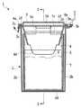
本発明の実施形態について、以下に図面に従って説明する。図1及び図2において、本発明の第1実施形態の詰替え可能な容器1(以下適宜「容器1」という)は、粉ミルクなどの粉状物の包装に用いられるものであり、容器本体2と、蓋体3と、リテーナ4と、ホルダ5とを有する。容器1は、内容物6が入れられた詰替え用の袋7を収容可能である。なお、内容物6は任意の粉体物又は粒体物とすることができる。 Embodiments of the present invention will be described below with reference to the drawings. 1 and 2, a refillable container 1 (hereinafter referred to as “container 1” as appropriate) according to the first embodiment of the present invention is used for packaging a powdery material such as powdered milk. A
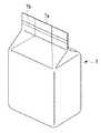
袋7は、周知のガセット袋であり、内容物6を収容した状態では、概ね矩形の底面形状を有する。図15に示されるように、袋7は、詰替え前には内容物6を収容した状態で密封されている。袋7は、封緘部7aにおいて、密封手段(例えばヒートシール)によって密封される。封緘部7aは、詰替えの際にユーザにより切り取り予定線7bに沿って切断され除去され、これによって袋7が開封される。切り取り予定線7bは、切り取りが袋7における予定された高さ位置で行われるように、開封案内構造(例えばミシン目など)によって構成されている。図16に示されるように、封緘部7aが除去されると、袋7には開封口7cが形成される。開封口7cには、ガセット袋の通常の仕様に起因して、内向きに折り込まれた内向きノッチ部7dが存在する。袋7の材料は任意であり、例えば樹脂フィルム、紙、不織布、金属箔又はこれらの任意の組合せからなるシート状材料を好適に用いることができる。 The
図1及び2において、容器本体2は、概ね直方体であって上面が開口部2a(図3参照)とされており、また前後壁2bと、左右壁2cと、底壁2dとを有する。容器本体2の内部は、底壁2dから開口部2aに向けていわゆる抜け勾配、すなわち底壁2dから開口部2aに向けて水平断面形状が徐々に拡大するように構成されている。開口部2aの近傍には、水平方向かつ外向きに突出する支持リム2e(図1参照)、及び上向きに突出する係合リム2f(図2参照)が設けられている。支持リム2eは、開口部2aの全周にわたって延在しており、後述するリテーナ4、ホルダ5及び蓋体3の支持を促進すると共に、容器本体2を補強している。係合リム2fは、開口部2aの全周のうち、後述するホルダ5の係合リム5h(図2参照)に相当する部分を除いた部分にわたって延在している。 1 and 2, the
蓋体3は、容器本体2の開口部2aを覆うように構成されている。蓋体3には、2つの支持アーム3a及びこれらに両端が固定された回動軸3b(図2・図9参照)を有する。回動軸3bに対応して、図4に示されるように、容器本体2には下向きアーム2g及び一対の上向きアーム2hが設けられている。下向きアーム2gの下面及び上向きアーム2hの上面にはそれぞれ溝が設けられており、これらの溝の間で回動軸3が挟まれて、回動自在に支持される。 The
蓋体3にはまた、可撓性のあるいは旋回可能な固定具3c(図1・図2・図4参照)が設けられている。固定具3cには係止孔3d(図1参照)が設けられており、これによって、固定具3cが容器本体2の係止片2i(図2参照)に係合し、蓋体3を閉鎖状態にロックすることができる。蓋体3の縁部には、その全周に亘り、後述するリテーナ4の嵌合部4aの上面に嵌合するための嵌合部3eが設けられている。この嵌合はスナップ係合とすることができる。 The
リテーナ4は、袋7の開封口7cの近傍に内方から接して、当該開封口7cを拡開状態に保持可能に構成されている。図1・図2・図5等に示されるように、リテーナ4は、嵌合部4aと、リテーナタブ4bと、ファンネル部4cとを有する。嵌合部4aは、容器本体2及びホルダ5に嵌合可能である。リテーナタブ4bは、ユーザによるリテーナ4の保持を促進するものであり、嵌合部4aの平面視における2つの短辺の中央部から、略水平方向かつ外向きにそれぞれ延在する。ファンネル部4cは、平面視で概ね矩形の環状ないし枠状をなしており、袋7の開封口7cの内側への挿入を支援するために、これに囲まれた部分の水平断面形状が下方ほど小さくされている。ファンネル部4cの平面視における2つの短辺の下端部には、袋7への挿入を容易にするための挿入補助片4dがそれぞれ斜め下向きに延設されている。 The
リテーナ4は更に、その形状を保持すると共に、不図示のスプーンで内容物6を取り出した後に、余分な量を掻きとって定量する為の仕切り板4e(図1・図5)を有する。 The
ホルダ5は、容器本体2に収容されること、袋7を収容すること、及びリテーナ4を保持することが可能である。ホルダ5は、筒状部5aと、下向きに延在する袋保持部5bと、上向きに延在する2つのアーム5c,5cとを有する。筒状部5aは、平面視で概ね矩形の環状ないし枠状をなしている。筒状部5aは、上方に向けていわゆる抜け勾配、すなわち上方に向けて水平断面形状が徐々に拡大するように構成されている。 The
袋保持部5bは、概ねループ状をなしており、筒状部5aの平面視における2つの長辺の各中央部分からそれぞれ下向きに延在する垂下片5d,5dと、これら垂下片5d,5dの下端部を連結する底部片5eとを有する。垂下片5d,5dの間隔も抜け勾配、すなわち上方に向けて間隔が徐々に拡大するように構成されている。底部片5eは、その概ね水平な上面で、袋7の底部を保持することができる。なお、図1・図2では理解の容易のために、袋7の底部が底部片5eから浮上して描かれているが、現実の使用の際には袋7の底部は底部片5eの上面に当接する。ホルダ5は底部片5eによって自立可能である。 The
袋保持部5bに隣接するホルダ5の左右側方には、2つの制御開口部5f,5fが形成される。制御開口部5f,5Fは十分な大きさを有するため、この制御開口部5f,5fを通じて、ホルダ5内に収容された袋7の外面に、ユーザがホルダ5の外から接触して、袋7の姿勢を制御することが可能である。制御開口部5f,5fは、ホルダ5の側面から底面に亘り延在しており、これによって袋7の側面及び底面をそれぞれ部分的に露出させている。 Two
2つのアーム5cは、筒状部5aの平面視における短辺の中央部から、斜め上向きに延在している。アーム5cの先端は、略水平方向かつ外向きに延在するホルダタブ5gとされている。ホルダタブ5gは、ユーザによるホルダ5の保持を促進するものである。上述したリテーナ4のリテーナタブ4bの外周縁部には、その全周にわたって、下向きに突出する係合リム4f(図1・図3参照)が設けられており、この係合リム4fによって、リテーナタブ4bとホルダタブ5gとを互いに嵌合させることができる。この嵌合はスナップ係合とすることができる。ホルダタブ5gはリテーナ4を保持することができ、したがって、ホルダタブ5gの上面は本発明におけるリテーナ保持部を構成する。 The two
ホルダタブ5gの基部には、上向きの係合リム5hが設けられている。係合リム5hには、上述したリテーナ4の嵌合部4aが嵌合する。係合リム5h及び嵌合部4aの少なくとも一方には、両者を互いにスナップ係合させるための構造、例えば突起、凹部や通孔を設けることができる。 An
アーム5cの上端部の近傍であってホルダタブ5gの下側には、図3に示されるように、容器本体2の開口部2aと嵌合するための突起5iが設けられている。この嵌合はスナップ係合とすることができる。突起5iはアーム5cの幅方向の全体に亘って延在していても良く、また一部のみに亘っていても、単一のアーム5cにつき複数設けても良い。 As shown in FIG. 3, a protrusion 5i for fitting with the
容器1の各部の材質には、任意のものを用いることができ、特に樹脂が好適である。例えば、容器本体2・蓋体3・ホルダ5をポリエチレンとし、リテーナ4をポリプロピレンとするのが特に好適であるが、これらに限られない。容器本体2・蓋体3・リテーナ4・ホルダ5のうち任意のものを、透明又は半透明としても良い。 Arbitrary things can be used for the material of each part of the container 1, and resin is especially suitable. For example, it is particularly preferable that the
以上のとおり構成された本発明の第1実施形態の容器1を用いて、袋7の詰め替えを行う方法について説明する。 A method for refilling the
まず、図6に示されるように、開封した袋7を、ホルダ5にセット(すなわち収容)する。袋7は、ホルダ5の袋保持部5bに保持され、袋7の底面がホルダ5の底部片5eの上面に接する。これによって、袋7の開封口7cとホルダ5との高さ方向の適切な相対位置関係が確立される。 First, as shown in FIG. 6, the opened
次に、図7に示されるように、袋7の開封口7cの内向きノッチ部7dをホルダ5の内周面に向けて外向きに拡げながら、リテーナ4をホルダ5にセット(すなわち収容)する。このときユーザは、リテーナ4のリテーナタブ4bを、ホルダ5のホルダタブ5gに嵌合させる。リテーナ4はホルダタブ5gの上面で保持される。その結果、リテーナ4によって袋7の開封口7cが拡開状態に保持され、かつそのときに、ホルダ5によって、リテーナ4と袋7との間の高さ方向の相対移動が規制され、袋7の開封口7cとリテーナ4との適切な相対位置関係が確立される。 Next, as shown in FIG. 7, the
このようにしてリテーナ4がホルダ5にセットされると、これらを容器本体2内にセットする前であれば、ホルダ5の制御開口部5f,5fを通じて、ホルダ5内に収容された袋7の外面に、ユーザがホルダ5の外から手指でアクセスすなわち接触して、ホルダ5内における袋7の姿勢を制御することが可能である。したがって、袋7の開封口7cの一部又は全部が、ホルダ5の筒状部5aとリテーナ4のファンネル部4cとの間から外れたり、筒状部5aとファンネル部4cとの間でしわになって詰まるなどの不適切なセット状態が生じた場合には、リテーナ4とホルダ5とを容器本体2内にセットする前であれば、これを容易に外部から視認できると共に、必要に応じてリテーナタブ4bとホルダタブ5gとの嵌合を解除してリテーナ4をホルダ5から浮上させ、制御開口部5fを通じた袋への直接のアクセスにより袋7の姿勢を変更してから、リテーナ4を再びセットするなどの修正を容易に行うことができる。 When the
次に、図8に示されるように、リテーナ4がセットされたホルダ5を、容器本体2内にセットする。このとき、ホルダ5によって袋7が保持されているため、袋7の開封口7cとリテーナ4との適切な相対位置関係を維持したまま、リテーナ4がセットされたホルダ5を容器本体2に収容することができる。また、ホルダ5の保持部5bによって、袋7の側面が保持されるため、袋7が重みで膨らみ挿入しづらくなる事態が防止され、セットし易くなる。リテーナ4の嵌合部4aは、容器本体2の係合リム2fに嵌合し、リテーナタブ4bは2つの係合リム2fの間の領域に納まる。ここでリテーナタブ4及びホルダタブ5の先端は、容器本体2の開口部の外縁(支持リム2eの外縁)よりも外向きに突出するので、ホルダ5を容器本体2内にセットする際に、リテーナタブ4及びホルダタブ5を把持した手指の容器本体2との干渉が抑制され、リテーナ4及びホルダ5を容器本体2にセットする作業を容易にすることができる。 Next, as shown in FIG. 8, the
以上のようにして、図9に示されるように、リテーナ4及びホルダ5が容器本体2内にセットされる。ユーザは蓋体3を閉じて、容器本体2の開口部を被覆し、固定具3cを容器本体2の係止片2iに係合させることで、蓋体3を閉鎖状態にロックすることができる。 As described above, the
以上のとおり、本実施形態の容器1は、容器本体2に収容されることが可能なホルダ5であって、リテーナ4を保持するためのリテーナ保持部、及び袋7の少なくとも下面を保持するための袋保持部5bを有するホルダ5を更に備えた。その結果、開封された袋7をホルダ5内に収容した状態で、リテーナ4によって袋7の開封口7cを拡開状態に保持するようにリテーナ4をリテーナ保持部(ホルダタブ5gの上面)で保持すると、ホルダ5によって、リテーナ4と袋7との間の高さ方向の相対移動が規制される。このため、開封された袋7をホルダ5内に収容してリテーナ4をセットする行程を、容器本体2の外で行うことにより、袋7の開封口7cとリテーナ4との適切な相対位置関係を容易に確立できると共に、この適切な相対位置関係を崩れないように維持したままこれらを容器本体2に収容することができ、したがって内容物6が容器本体2内に漏出するおそれを抑制することができる。 As described above, the container 1 of the present embodiment is a
また、本実施形態では、ホルダ5はその側面及び底面の少なくとも一方に少なくとも1つの制御開口部5fを有し、当該制御開口部5fを通じて、ホルダ5内に収容された袋7の外面にユーザがホルダ5の外から接触して袋7の姿勢を制御可能である。したがって、開封された袋7をホルダ5内に収容してリテーナ4をセットする行程を、容器本体2の外で行うときに、袋7の開封口7cとリテーナ4との適切な相対位置関係の確立や再確立を更に容易化することができる。 Further, in the present embodiment, the
また、本実施形態では、少なくとも一つの制御開口部5fは、ホルダ5の側面から底面に亘り延在している。したがって、袋7の姿勢の水平方向の変更と上下方向の変更とを容易化することができる。 In the present embodiment, at least one
また、本実施形態では、開封された袋7をホルダ5内に収容した状態で、リテーナ4によって袋7の開封口7cを拡開状態に保持するようにリテーナ4をリテーナ保持部(ホルダタブ5gの上面)で保持すると、袋7の開封口7cの少なくとも一部の移動(特に、水平方向の移動)が、リテーナ4の外面とホルダ5の内面とによって規制される。その結果、リテーナ4とホルダ5との間における袋7のしわや折れの発生が抑制され、これによって、袋7の開封口7cとリテーナ4との相対位置関係の悪化や、両者の間の隙間の発生及び拡大を抑制することができる。 In the present embodiment, the
また、本実施形態では、開封された袋7をホルダ5内に収容した状態で、リテーナ4によって袋7の開封口7cを拡開状態に保持するようにリテーナ4をリテーナ保持部(ホルダタブ5gの上面)で保持すると、リテーナ4の外面とホルダ5の内面との間で、袋7の開封口7cの少なくとも一部が挟持される。したがって、袋7の開封口7cとリテーナ4との相対位置関係の悪化や、両者の間の隙間の発生及び拡大を、更に効果的に抑制することができる。なお、リテーナ4の外面とホルダ5の内面との間における開封口7cの移動の規制及び挟持は、いずれも、リテーナ4及びホルダ5の全周にわたる領域で行われてもよく、また一部のみで行われても良い。 In the present embodiment, the
また、本実施形態では、ホルダ5の上面開口部には、略水平方向かつ外向きに延在するホルダタブ5gが設けられており、ホルダタブ5gの先端は、ホルダ5が容器本体2に収容されているときに、容器本体2の開口部の外縁よりも外向きに突出する。したがって、ホルダ5を容器本体2内にセットする際に、ホルダタブ5gを把持した手指の容器本体2の開口部との干渉が抑制されるので、袋7が収容されリテーナ4がセットされたホルダ5を、容器本体2にセットする作業、及び容器本体2から取り外す作業を容易にすることができる。但しホルダタブ5gの存在しない領域においては、容器本体2の支持リム2e(図1・図3参照)はホルダタブ5g及びリテーナタブ4bと等しい側方位置や、これらよりも外側の側方位置にまで延在していても良い。 Moreover, in this embodiment, the
また、本実施形態では、容器1は、リテーナ4とホルダ5とを互いに固定するための固定構造である係合リム4fを更に備える。したがって、袋7の開封口7cとリテーナ4との相対位置関係を好適に維持でき、詰替え時や詰替え後における漏出の抑制を更に促進することができる。なお、リテーナ4とホルダ5とを互いに固定するための固定構造は、本実施形態における態様に限られず、各種の他の固定構造を採用できる。そのような他の固定構造は、例えばリテーナ4とホルダ5との一方に設けた突起が、他方に設けた相補構造の孔に嵌合する形式のものであってもよい。固定構造としてはスナップ係合を用いるものが、係合及び分離の繰返しが可能である点で特に好適である。 In the present embodiment, the container 1 further includes an
本実施形態に係る容器1を用いて、容器1の内部に、内容物6が入れられた袋7であって未開封のものを収容してなる包装体(図示せず)を構成することができる。この態様によれば、内容物6が入れられた袋7と容器とを一体的に製造・流通・販売することができ好適である。 Using the container 1 according to the present embodiment, a package body (not shown) configured to accommodate an
なお、リテーナ4をホルダ5にセットしたとき、リテーナ4のファンネル部4cと、ホルダ5の筒状部5aとの間には、隙間があってもなくても良い。隙間がない場合には、ファンネル部4cと筒状部5aとの間で、袋7の開封口7cが挟持されることになり、リテーナ4と袋7との間からの内容物6の漏出を抑制でき、またこの挟持に係る摩擦力によって、リテーナ4と袋7の相対位置関係を好適に維持することができる。また隙間が多少ある場合にも、ファンネル部4cと筒状部5aとの間で、袋7の開封口7cの移動が規制されることになり、袋7のしわや折れの発生を抑制できるため、リテーナ4と袋7との相対位置関係を好適に維持することができる。隙間が小さいほど、内容物6の漏れを抑制するために有利であるが、この目的でリテーナ4のファンネル部4cの水平断面形状をより大きく設計すると、それだけ、リテーナ4をセットする際に袋7の開封口7cの近傍を座屈させてしまい、当該間隙の密封を促進できないおそれが大きくなってしまう。したがって、当該隙間の大きさは、袋7の素材の機械的特性(特に硬さ)などに応じて実験的に定めるのが好適である。 When the
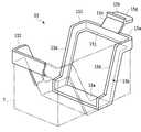
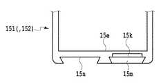
次に、本発明の第2実施形態について説明する。図10ないし図12に示される第2実施形態は、リテーナ14及びホルダ15を用いるものである。図10において、ホルダ15は、第1半体151と、第2半体152とから構成されている。これら第1半体151、第2半体152は、概ね互いに同一の形状を有するが、第1半体151にのみ、アーム15cが設けられている。アーム15cには、ホルダタブ15g及び係合リム15hが設けられている。これらアーム15c、ホルダタブ15g及び係合リム15hの形状及び構造は、上述した第1実施形態におけるアーム5c、ホルダタブ5g及び係合リム5hとそれぞれ同様である。第1半体151は、ループ状の袋保持部15bを有し、袋保持部15bは、2つの斜行片15d,15d及び底部片15eから構成されている。袋7の底部は、底部片15eの上面に当接して支持される。第1半体151の短辺15aと、2つの斜行片15d,15dとにわたって、畝状のリブ15jが設けられている。 Next, a second embodiment of the present invention will be described. The second embodiment shown in FIGS. 10 to 12 uses a
第1半体151と第2半体152とを相互に結合するための結合構造は、図10では図示を省略されており、図11・図12に示されている。図11・図12において、底部片15eには、先端に爪15kを有する嵌合突起15mと、この嵌合突起15mと相補的な断面形状を有する嵌合溝15nとが設けられている。嵌合溝15nの奥には、爪15kが嵌合可能な係合部15pが設けられている。嵌合溝15nの断面形状は、図12に示されるような蟻溝形である。 The coupling structure for coupling the
図13において、リテーナ14は、嵌合部14aと、リテーナタブ14bと、ファンネル部14cとを有する。第1半体151にのみホルダタブ15gが設けられていることに対応して、リテーナタブ14bは1つだけ設けられている。リテーナタブ14の先端には、ホルダタブ15gと嵌合するための係合リム14fが設けられている。 In FIG. 13, the
ファンネル部14cは、概ね鉛直方向に延在する鉛直壁部14gと、その下端部から斜行する斜行壁部14hとを有する。これら鉛直壁部14gと斜行壁部14hとの境界である頂部14iは、ホルダ15にリテーナ14がセットされたときに、ホルダ15のリブ15jよりもわずかに上に位置し、かつ頂部14iの頂点がリブ15jの頂点よりも外側に位置する。これによって、セットされた袋7の開封部7cの近傍を略クランク状にわずかに弾性変形させ、その姿勢及び形状の維持を促進することができる。このとき、ファンネル部14cとリブ15jとの間には隙間があってもなくても良い。 The
リテーナ14はまた、ホルダ15にセットされたときに第2半体152の短辺15aを挟持するための挟持片14jを有する。挟持片14jは短辺15aの両端部を挟持するように、平面視におけるリテーナ14の短辺の2箇所に設けられているが、短辺15aの全体にわたる幅に設けても良い。第2実施形態の残余の構成は、上述した第1実施形態と同様である。 The
以上のとおり構成された第2実施形態では、開封した袋7を、ホルダ15にセット(すなわち収容)し、次に、袋7の開封口7cをホルダ15の内周面に向けて外向きに拡げながら、リテーナ4をホルダ5にセット(すなわち収容)する。このとき、袋7の開封口7cは、その図13中の左右両端部において、リテーナ14のファンネル部14cとホルダ15の短辺15aとの間に配置される。開封口7cの移動は、リテーナ14のファンネル部14cの外面とホルダ15の短辺15aの内面とによって規制される。 In the second embodiment configured as described above, the opened
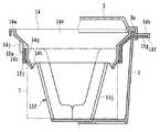
図14は、ホルダの別の構成例を示す。別の構成例に係るホルダ25は、第1半体251及び第2半体252を有する。これら第1半体251及び第2半体252は、例えば射出成型により一体的に形成され、両者の間にヒンジ部25aを有する。第2半体252には、先端に爪25bを有する嵌合突起25cが設けられ、第1半体251には、爪25bと相補的な断面形状を有する係合溝25cが設けられている。ヒンジ部25aを支点に、第2半体を図中矢印A方向に旋回させ、二点鎖線Bの姿勢に引き起こして、爪25bと係合溝25cとを係合させることにより、ホルダ25を使用可能な状態にすることができる。なお、この別の構成例に係るホルダ25では、第1半体251及び第2半体252の両方にアーム15c、ホルダタブ15g及び係合リム15hが設けられている。この変形例のホルダ25によれば、第1半体251と第2半体252とを一体的に製造及び管理でき、また組立前の保管スペースを抑制することができる。 FIG. 14 shows another configuration example of the holder. The
なお、本発明の範囲は上記各実施形態のみに限らず、特許請求の範囲によって規定される本発明の思想に包含されるあらゆる変形例や応用例、均等物が本発明に含まれる。従って本発明は、限定的に解釈されるべきではなく、本発明の思想の範囲内に帰属する他の任意の技術にも適用することが可能である。例えば、ホルダの袋保持部はループ状としたが、袋の下面の少なくとも一部を保持しうるもの、特に水平方向に延在する要素を有するものであれば、ループ状に限らず他の形状であっても良い。 Note that the scope of the present invention is not limited to the above-described embodiments, and includes all modifications, applications, and equivalents included in the concept of the present invention defined by the claims. Therefore, the present invention should not be construed as being limited, and can be applied to any other technique belonging to the scope of the idea of the present invention. For example, the bag holding portion of the holder has a loop shape, but is not limited to the loop shape, as long as it can hold at least a part of the lower surface of the bag, and particularly has an element extending in the horizontal direction. It may be.
制御開口部のないホルダを用いても良い。制御開口部はホルダの側面のみ、あるいは底面のみにわたるものであっても良く、位置・形状及び個数は任意である。ホルダタブ及びリテーナタブの位置・形状及び個数も任意である。ホルダタブ及びリテーナタブの形状は、互いに対応していなくても良い。ホルダタブ及びリテーナタブとは別途に、前記リテーナを保持するためのリテーナ保持部や、リテーナとホルダとを互いに固定するための固定構造を設けても良い。ホルダはその一部又は全部がメッシュ状ないし多孔状であっても良い。 A holder without a control opening may be used. The control opening may extend only on the side surface of the holder or only on the bottom surface, and the position, shape and number are arbitrary. The position, shape, and number of holder tabs and retainer tabs are also arbitrary. The shapes of the holder tab and the retainer tab may not correspond to each other. In addition to the holder tab and the retainer tab, a retainer holding portion for holding the retainer and a fixing structure for fixing the retainer and the holder to each other may be provided. A part or all of the holder may be mesh or porous.
本発明の容器は、食品以外の他の物品、例えば粉状洗剤などの包装にも使用できる。また上記各実施形態では、容器及び袋の平面視形状は略矩形としたが、円形や楕円形など他の形状であっても良く、かかる構成も本発明の範疇に属するものである。 The container of the present invention can also be used for packaging other articles than food, such as powder detergents. In each of the above embodiments, the shape of the container and the bag in plan view is substantially rectangular. However, other shapes such as a circle and an ellipse may be used, and such a configuration also belongs to the category of the present invention.
1 詰替え可能な容器
2 容器本体
3 蓋体
4 リテーナ
4b リテーナタブ
4f 係合リム
5,15,25 ホルダ
5b 袋保持部
5f,15f,25f 制御開口部
5g,15g ホルダタブ
6 内容物
7 袋DESCRIPTION OF SYMBOLS 1
Claims (8)
Translated fromJapanese前記袋の開封口の近傍に内方から接して当該開封口を拡開状態に保持可能なリテーナと、
を備えた詰替え可能な容器であって、
前記容器本体に収容されること、前記袋を収容すること、及び前記リテーナを保持することが可能なホルダであって、前記リテーナを保持するためのリテーナ保持部、及び前記袋の少なくとも下面を保持するための袋保持部を有するホルダを更に備え、
開封された前記袋を前記ホルダ内に収容した状態で、前記リテーナによって前記袋の前記開封口を拡開状態に保持するように前記リテーナを前記リテーナ保持部で保持したときに、前記ホルダによって、前記リテーナと前記袋との間の高さ方向の相対移動が規制されることを特徴とする詰替え可能な容器。A container body capable of accommodating a bag containing contents;
A retainer capable of contacting the inside of the opening of the bag from the inside and holding the opening in an expanded state;
A refillable container comprising:
A holder capable of being accommodated in the container body, accommodating the bag, and retaining the retainer, and retainer holding portion for retaining the retainer, and at least a lower surface of the bag A holder having a bag holding part for
When the retainer is held by the retainer holding part so that the opening of the bag is held in an expanded state by the retainer while the opened bag is accommodated in the holder, A refillable container characterized in that relative movement in the height direction between the retainer and the bag is restricted.
前記ホルダはその側面及び底面の少なくとも一方に少なくとも1つの制御開口部を有し、当該制御開口部を通じて、当該ホルダ内に収容された前記袋の外面にユーザが前記ホルダの外から接触して前記袋の姿勢を制御可能であることを特徴とする詰替え可能な容器。Refillable container according to claim 1,
The holder has at least one control opening on at least one of a side surface and a bottom surface thereof, and the user comes into contact with the outer surface of the bag accommodated in the holder from the outside of the holder through the control opening. A refillable container characterized in that the posture of the bag can be controlled.
少なくとも一つの前記制御開口部は、前記ホルダの側面から底面に亘り延在していることを特徴とする詰替え可能な容器。A refillable container according to claim 1 or 2,
The refillable container, wherein at least one of the control openings extends from a side surface to a bottom surface of the holder.
開封された前記袋を前記ホルダ内に収容した状態で、前記リテーナによって前記袋の前記開封口を拡開状態に保持するように前記リテーナを前記リテーナ保持部で保持すると、前記袋の前記開封口の少なくとも一部の移動が、前記リテーナの外面と前記ホルダの内面とによって規制されることを特徴とする詰替え可能な容器。A refillable container according to any one of claims 1 to 3,
When the retainer is held by the retainer holding part so that the opening of the bag is held in an expanded state by the retainer in a state where the opened bag is accommodated in the holder, the opening of the bag The refillable container is characterized in that at least a part of the movement is restricted by the outer surface of the retainer and the inner surface of the holder.
開封された前記袋を前記ホルダ内に収容した状態で、前記リテーナによって前記袋の前記開封口を拡開状態に保持するように前記リテーナを前記リテーナ保持部で保持すると、前記リテーナの外面と前記ホルダの内面との間で、前記袋の開封口の少なくとも一部が挟持されることを特徴とする詰替え可能な容器。Refillable container according to claim 4,
When the retainer is held by the retainer holding portion so that the opening of the bag is held in an expanded state by the retainer in a state where the opened bag is accommodated in the holder, the outer surface of the retainer and the retainer A refillable container, wherein at least a part of the opening of the bag is sandwiched between the inner surface of the holder.
前記ホルダの前記上面開口部には、略水平方向かつ外向きに延在するホルダタブが設けられており、
当該ホルダタブの先端は、前記ホルダが前記容器本体に収容されているときに、前記容器本体の開口部の外縁よりも外向きに突出することを特徴とする詰替え可能な容器。A refillable container according to any one of claims 1 to 5,
The upper surface opening of the holder is provided with a holder tab extending substantially horizontally and outwardly,
The refillable container, wherein the tip of the holder tab protrudes outward from the outer edge of the opening of the container body when the holder is accommodated in the container body.
前記リテーナと前記ホルダとを互いに固定するための固定構造を更に備えたことを特徴とする詰替え可能な容器。A refillable container according to any one of claims 1 to 6,
A refillable container, further comprising a fixing structure for fixing the retainer and the holder to each other.
Priority Applications (1)
| Application Number | Priority Date | Filing Date | Title |
|---|---|---|---|
| JP2014229035AJP6515494B2 (en) | 2014-11-11 | 2014-11-11 | Refillable container and package |
Applications Claiming Priority (1)
| Application Number | Priority Date | Filing Date | Title |
|---|---|---|---|
| JP2014229035AJP6515494B2 (en) | 2014-11-11 | 2014-11-11 | Refillable container and package |
Publications (2)
| Publication Number | Publication Date |
|---|---|
| JP2016088613Atrue JP2016088613A (en) | 2016-05-23 |
| JP6515494B2 JP6515494B2 (en) | 2019-05-22 |
Family
ID=56018412
Family Applications (1)
| Application Number | Title | Priority Date | Filing Date |
|---|---|---|---|
| JP2014229035AActiveJP6515494B2 (en) | 2014-11-11 | 2014-11-11 | Refillable container and package |
Country Status (1)
| Country | Link |
|---|---|
| JP (1) | JP6515494B2 (en) |
Citations (4)
| Publication number | Priority date | Publication date | Assignee | Title |
|---|---|---|---|---|
| US2352503A (en)* | 1941-04-16 | 1944-06-27 | Container Corp | Container |
| JP2003165575A (en)* | 2001-09-18 | 2003-06-10 | Wakoudou Kk | Powder storage container and inner lid member for the powder storage container |
| JP2005053536A (en)* | 2003-08-04 | 2005-03-03 | Yoshikazu Taniguchi | Storage box |
| JP2014208540A (en)* | 2013-03-29 | 2014-11-06 | 株式会社吉野工業所 | Storage case |
- 2014
- 2014-11-11JPJP2014229035Apatent/JP6515494B2/enactiveActive
Patent Citations (4)
| Publication number | Priority date | Publication date | Assignee | Title |
|---|---|---|---|---|
| US2352503A (en)* | 1941-04-16 | 1944-06-27 | Container Corp | Container |
| JP2003165575A (en)* | 2001-09-18 | 2003-06-10 | Wakoudou Kk | Powder storage container and inner lid member for the powder storage container |
| JP2005053536A (en)* | 2003-08-04 | 2005-03-03 | Yoshikazu Taniguchi | Storage box |
| JP2014208540A (en)* | 2013-03-29 | 2014-11-06 | 株式会社吉野工業所 | Storage case |
Also Published As
| Publication number | Publication date |
|---|---|
| JP6515494B2 (en) | 2019-05-22 |
Similar Documents
| Publication | Publication Date | Title |
|---|---|---|
| JP2015042560A (en) | Packaging stopper and packaging box connected using the same | |
| JP2019151386A (en) | Household tissue paper storage container | |
| JP2017013854A (en) | Structure | |
| JP2015196520A (en) | Container for microwave oven and package for microwave oven | |
| JP2016088613A (en) | Refillable containers and packages | |
| JP5748973B2 (en) | Volatilizer container | |
| JP6286267B2 (en) | Exterior container and filling container | |
| JP2016084157A (en) | Refillable container and package | |
| JP6994985B2 (en) | Storage container | |
| JP6586798B2 (en) | Storage container | |
| JP7300837B2 (en) | Household tissue paper storage container | |
| JP6757045B2 (en) | container | |
| JP2015146932A (en) | Extraction bag and packaging sheet | |
| JP3217964U (en) | Buffer for packing semiconductor wafer storage container | |
| JP6982929B2 (en) | Refill packaging for cosmetics and refill packaging containers for cosmetics | |
| KR200477901Y1 (en) | packaging container | |
| JP5117237B2 (en) | Household thin paper storage container | |
| JP3209888U (en) | Packaging container, wet sheet packaging structure | |
| JP2012197110A (en) | Gusset bag and refilling container set | |
| JP2019196222A (en) | Pouch container dispenser | |
| JP5862169B2 (en) | Dripper | |
| JP2008230649A (en) | Packaging bag | |
| JP2013067403A (en) | Spout | |
| WO2024224718A1 (en) | Container set, container holder, and bag container | |
| KR102050781B1 (en) | Container for packing a food |
Legal Events
| Date | Code | Title | Description |
|---|---|---|---|
| A621 | Written request for application examination | Free format text:JAPANESE INTERMEDIATE CODE: A621 Effective date:20171019 | |
| A977 | Report on retrieval | Free format text:JAPANESE INTERMEDIATE CODE: A971007 Effective date:20180717 | |
| A131 | Notification of reasons for refusal | Free format text:JAPANESE INTERMEDIATE CODE: A131 Effective date:20180821 | |
| A521 | Request for written amendment filed | Free format text:JAPANESE INTERMEDIATE CODE: A523 Effective date:20181019 | |
| TRDD | Decision of grant or rejection written | ||
| A01 | Written decision to grant a patent or to grant a registration (utility model) | Free format text:JAPANESE INTERMEDIATE CODE: A01 Effective date:20190319 | |
| A61 | First payment of annual fees (during grant procedure) | Free format text:JAPANESE INTERMEDIATE CODE: A61 Effective date:20190401 | |
| R150 | Certificate of patent or registration of utility model | Ref document number:6515494 Country of ref document:JP Free format text:JAPANESE INTERMEDIATE CODE: R150 | |
| R250 | Receipt of annual fees | Free format text:JAPANESE INTERMEDIATE CODE: R250 | |
| R250 | Receipt of annual fees | Free format text:JAPANESE INTERMEDIATE CODE: R250 | |
| R250 | Receipt of annual fees | Free format text:JAPANESE INTERMEDIATE CODE: R250 | |
| R250 | Receipt of annual fees | Free format text:JAPANESE INTERMEDIATE CODE: R250 |