JP2016087409A - Joint assembly, connection set including the joint assembly, and assembly set including the connection set - Google Patents
Joint assembly, connection set including the joint assembly, and assembly set including the connection setDownload PDFInfo
- Publication number
- JP2016087409A JP2016087409AJP2015033724AJP2015033724AJP2016087409AJP 2016087409 AJP2016087409 AJP 2016087409AJP 2015033724 AJP2015033724 AJP 2015033724AJP 2015033724 AJP2015033724 AJP 2015033724AJP 2016087409 AJP2016087409 AJP 2016087409A
- Authority
- JP
- Japan
- Prior art keywords
- connecting portion
- rotation axis
- fitting
- rotation
- rotating member
- Prior art date
- Legal status (The legal status is an assumption and is not a legal conclusion. Google has not performed a legal analysis and makes no representation as to the accuracy of the status listed.)
- Pending
Links
- 230000037431insertionEffects0.000claimsdescription39
- 238000003780insertionMethods0.000claimsdescription39
- 230000004308accommodationEffects0.000claimsdescription28
- 230000002093peripheral effectEffects0.000claimsdescription15
- 238000005553drillingMethods0.000claimsdescription2
- 230000008878couplingEffects0.000abstractdescription6
- 238000010168coupling processMethods0.000abstractdescription6
- 238000005859coupling reactionMethods0.000abstractdescription6
- 238000009434installationMethods0.000description3
- 238000004519manufacturing processMethods0.000description1
Images


Classifications
- F—MECHANICAL ENGINEERING; LIGHTING; HEATING; WEAPONS; BLASTING
- F16—ENGINEERING ELEMENTS AND UNITS; GENERAL MEASURES FOR PRODUCING AND MAINTAINING EFFECTIVE FUNCTIONING OF MACHINES OR INSTALLATIONS; THERMAL INSULATION IN GENERAL
- F16B—DEVICES FOR FASTENING OR SECURING CONSTRUCTIONAL ELEMENTS OR MACHINE PARTS TOGETHER, e.g. NAILS, BOLTS, CIRCLIPS, CLAMPS, CLIPS OR WEDGES; JOINTS OR JOINTING
- F16B2/00—Friction-grip releasable fastenings
- F16B2/20—Clips, i.e. with gripping action effected solely by the inherent resistance to deformation of the material of the fastening
- A—HUMAN NECESSITIES
- A63—SPORTS; GAMES; AMUSEMENTS
- A63H—TOYS, e.g. TOPS, DOLLS, HOOPS OR BUILDING BLOCKS
- A63H33/00—Other toys
- A63H33/04—Building blocks, strips, or similar building parts
- A63H33/042—Mechanical, electrical, optical, pneumatic or hydraulic arrangements; Motors
- F—MECHANICAL ENGINEERING; LIGHTING; HEATING; WEAPONS; BLASTING
- F16—ENGINEERING ELEMENTS AND UNITS; GENERAL MEASURES FOR PRODUCING AND MAINTAINING EFFECTIVE FUNCTIONING OF MACHINES OR INSTALLATIONS; THERMAL INSULATION IN GENERAL
- F16B—DEVICES FOR FASTENING OR SECURING CONSTRUCTIONAL ELEMENTS OR MACHINE PARTS TOGETHER, e.g. NAILS, BOLTS, CIRCLIPS, CLAMPS, CLIPS OR WEDGES; JOINTS OR JOINTING
- F16B7/00—Connections of rods or tubes, e.g. of non-circular section, mutually, including resilient connections
- F16B7/04—Clamping or clipping connections
- F—MECHANICAL ENGINEERING; LIGHTING; HEATING; WEAPONS; BLASTING
- F16—ENGINEERING ELEMENTS AND UNITS; GENERAL MEASURES FOR PRODUCING AND MAINTAINING EFFECTIVE FUNCTIONING OF MACHINES OR INSTALLATIONS; THERMAL INSULATION IN GENERAL
- F16C—SHAFTS; FLEXIBLE SHAFTS; ELEMENTS OR CRANKSHAFT MECHANISMS; ROTARY BODIES OTHER THAN GEARING ELEMENTS; BEARINGS
- F16C11/00—Pivots; Pivotal connections
- F16C11/04—Pivotal connections
- F16C11/045—Pivotal connections with at least a pair of arms pivoting relatively to at least one other arm, all arms being mounted on one pin
- F—MECHANICAL ENGINEERING; LIGHTING; HEATING; WEAPONS; BLASTING
- F16—ENGINEERING ELEMENTS AND UNITS; GENERAL MEASURES FOR PRODUCING AND MAINTAINING EFFECTIVE FUNCTIONING OF MACHINES OR INSTALLATIONS; THERMAL INSULATION IN GENERAL
- F16C—SHAFTS; FLEXIBLE SHAFTS; ELEMENTS OR CRANKSHAFT MECHANISMS; ROTARY BODIES OTHER THAN GEARING ELEMENTS; BEARINGS
- F16C11/00—Pivots; Pivotal connections
- F16C11/04—Pivotal connections
- F16C11/06—Ball-joints; Other joints having more than one degree of angular freedom, i.e. universal joints
- F16C11/0604—Construction of the male part
- F16C11/0609—Construction of the male part made from two or more parts
Landscapes
- Engineering & Computer Science (AREA)
- General Engineering & Computer Science (AREA)
- Mechanical Engineering (AREA)
- Pivots And Pivotal Connections (AREA)
- Toys (AREA)
Abstract
Description
Translated fromJapanese本発明は、組立関節に関し、特に組立式のおもちゃに使用される組立関節に関する。 The present invention relates to an assembly joint, and more particularly to an assembly joint used for an assembly type toy.
たくさんの部材により組成される組立式のおもちゃには、各部材を互いに可動的に接続するために、一般に関節、例えば特許文献1に記載されている関節を用いて接続する。 In order to connect the members movably to each other, the assembled toy composed of many members is generally connected using a joint, for example, a joint described in Patent Document 1.
特許文献1に記載されている関節は、図1に示されるように、一端に第1の枢接部111が形成されている第1の回動部11と、一端に第2の枢接部121が形成されている第2の回動部12と、係合部材13と、により構成されている。第1の回動部11と第2の回動部12とは、所定の軸線L1を軸心として相対的に回動できるように、係合部材13により第1の枢接部111及び第2の枢接部121が互いに枢接されている。 As shown in FIG. 1, the joint described in Patent Document 1 includes a
しかし、特許文献1に記載されている関節は、第1の枢接部111及び第2の枢接部121が、所定の軸線L1を軸心としてしか回動できないので、可動範囲が狭いという欠点がある。 However, the joint described in Patent Document 1 has a drawback that the movable range is narrow because the first
また、関節以外に、例えば特許文献2に記載されている係合装置を用いて接続することもできる。 Moreover, it can also connect using the engaging apparatus described in
特許文献2に記載されている係合装置は、図2に示されるように、複数の円形の係合孔141が開けられているメス部材14と、円柱状に形成されているオス部材15と、により構成されている。オス部材15は、真中から外側へ張り出すように形成されているフランジ部151を有している。オス部材15の一端をフランジ部151に当接するまで係合孔141に挿し込むことにより、メス部材14はオス部材15と係合することができる。また、オス部材15は、その他端が他の係合孔141が開けられている部材に挿し込んで係合することができる。 As shown in FIG. 2, the engagement device described in
また、図3に示されるように、オス部材15には、取外し孔152が更に開けられている。オス部材15をメス部材14から取り外す際に、棒などの道具を取外し孔152に挿し込み、てこの原理でオス部材15をメス部材14から取り外すことができる。 As shown in FIG. 3, the
しかし、特許文献2に記載されている係合装置は、オス部材15と係合孔141の周縁との間の摩擦力だけで係合するので、製造精度が足りなければ、該2つのパーツを係合する摩擦力が生じず、または挿し込むこと自体ができないことが起こる恐れがある。また、オス部材15は円形に形成されているので、メス部材14はオス部材15を軸心として回転できて、その回転により両部材の間の係合姿勢を維持しにくく、更にメス部材14がオス部材15から外れる恐れもある。 However, since the engagement device described in
上記問題点に鑑みて、本発明は、関節の枢接部分がより多い回転方向で回転可能な組立関節の提供を目的とする。 In view of the above-described problems, an object of the present invention is to provide an assembly joint that can rotate in a rotation direction in which the joint portion of the joint is larger.
上記目的を達成すべく、本発明は、所定の第1の回転軸線に沿って延伸する連接柱と、前記連接柱の一端に配置されている第1の連結部と、中空に形成されて前記第1の連結部を外から包みながら、前記第1の連結部に対して前記第1の回転軸線を軸心として相対的に回動できるように前記第1の連結部に取付けられている回動部材と、前記回動部材を更に外から包みながら、前記回動部材に対して前記第1の回転軸線と略直交する第2の回転軸線を軸心として相対的に回動できるように取付けられている第2の連結部と、を有していることを特徴とする組立関節を提供する。 In order to achieve the above-mentioned object, the present invention provides a connecting column extending along a predetermined first rotation axis, a first connecting portion disposed at one end of the connecting column, and formed in a hollow shape. While wrapping the first connection portion from the outside, a rotation attached to the first connection portion so that the first connection portion can be rotated relative to the first connection portion with the first rotation axis as an axis. The moving member and the rotating member are wrapped so as to be relatively rotatable about the second rotating axis that is substantially orthogonal to the first rotating axis while wrapping the rotating member from the outside. And a second connecting portion. The assembly joint is provided with the second connecting portion.
また、本発明は、上記の組立関節、及び、第1の開口を有する収容空間が開けられている本体部材と、前記収容空間に挿し込んで前記本体部材に接続できる接続部材とを有する接続装置、を備える接続セットであって、前記接続部材は、所定の延伸方向に沿って延伸するように形成される柱状の基部と、前記基部の一端から外側へ張り出し、前記所定の延伸方向と直交する断面が非円形になっている第1のフランジ部と、前記基部の前記一端から更に延伸して前記収容空間に挿し込むことができ、且つ可撓性を有し前記基部に対して揺動できるように形成される第1の挿入部と、前記第1の挿入部の前記収容空間に挿し込むことができる先端に形成される第1の係合突起と、を有するように形成されており、前記本体部材は、前記第1の開口の端縁が前記第1のフランジ部の非円形断面に対応して前記第1のフランジ部を受入れることができるように形成されていると共に、前記収容空間内に、前記接続部材の前記第1の挿入部が前記収容空間に挿入まれる際に、前記第1の挿入部が前記収容空間に挿し込まれる方向における両端がそれぞれ前記第1のフランジ部と前記第1の係合突起とに当接して前記第1の挿入部を係止することができる縮径部が形成されていることを特徴とする接続セットをも提供する。 In addition, the present invention provides a connecting device including the above-described assembly joint, a main body member in which a housing space having a first opening is opened, and a connecting member that can be inserted into the housing space and connected to the main body member. The connection member includes a columnar base formed so as to extend along a predetermined extending direction, and projects outward from one end of the base, and is orthogonal to the predetermined extending direction. A first flange portion having a non-circular cross section, and can be further extended from the one end of the base portion and inserted into the accommodating space, and has flexibility and can swing with respect to the base portion. A first insertion portion formed as described above, and a first engagement protrusion formed at a tip that can be inserted into the accommodation space of the first insertion portion, The main body member has the first opening. An end edge is formed so as to be able to receive the first flange portion corresponding to a non-circular cross section of the first flange portion, and the first space of the connection member is formed in the housing space. When the insertion portion is inserted into the accommodation space, both ends in the direction in which the first insertion portion is inserted into the accommodation space abut against the first flange portion and the first engagement protrusion, respectively. The connection set is also characterized in that a reduced diameter portion capable of locking the first insertion portion is formed.
更に、本発明は、上記の接続セット、及び、前記接続セットが有する前記接続部材を前記本体部材から取り外すことができる取外し道具、を有する組立セットであって、前記取外し道具は、手で操作しやすいように所定の延伸方向に沿って延伸して形成される把握部と、前記接続部材の前記基部に対応して、前記第1のフランジ部と前記第2のフランジ部との間にある箇所を両側から挟むことができるように二股に分かれる2つの取外し突起を有する挟持部と、を有し、前記接続部材の前記第1のフランジ部が前記第1の開口に嵌まり込むように前記接続部材が前記本体部材の前記収容空間に挿し込まれて係合されている際、前記2つの取外し突起が前記基部の両側を挟むと、前記挟持部が前記第1の開口の端縁に接触してその接触部分を支点として前記2つの取外し突起が前記第2のフランジ部に当接するように前記把握部を揺動すると、前記2つの取外し突起が前記第2のフランジ部に対して、前記接続部材が前記収容空間に挿し込まれる方向の反対方向に向かう力を加えるによって、前記接続部材を前記収容空間から引き抜くことができることを特徴とする組立セットをも提供する。 Furthermore, the present invention is an assembly set comprising the above connection set and a removal tool capable of removing the connection member of the connection set from the main body member, wherein the removal tool is operated by hand. A location between the first flange portion and the second flange portion corresponding to the base portion of the connection member and a grasping portion formed by extending along a predetermined extending direction so as to be easy A clamping portion having two removal projections that are split into two so as to be sandwiched from both sides, and the connection is performed so that the first flange portion of the connection member fits into the first opening. When the two removal projections sandwich the both sides of the base portion when the member is inserted and engaged in the housing space of the main body member, the sandwiching portion comes into contact with the edge of the first opening. Support the contact When the grasping portion is swung so that the two removal protrusions are in contact with the second flange portion, the two removal protrusions are in contact with the second flange portion, and the connection member is in the housing space. An assembly set is also provided in which the connecting member can be pulled out from the housing space by applying a force in the direction opposite to the insertion direction.
上記の構成によれば、本発明は、第1の連結部が回動部材に取り付けられている上、その回動部材が更に第2の連結部に取り付けられているので、第1の連結部は、回動部材と共に所定の第2の回転軸線を軸心として回転できるだけでなく、更に所定の第1の回転軸線を軸心としても回転できる。従って、従来の組立関節と比べて、より多い回転方向で枢接部分が回転可能な組立関節を提供することができる。 According to the above configuration, the first connecting portion is attached to the rotating member, and the rotating member is further attached to the second connecting portion. In addition to rotating with the rotating member about the predetermined second rotation axis, it can also rotate about the predetermined first rotation axis. Therefore, it is possible to provide an assembly joint in which the pivotal portion can rotate in a larger number of rotation directions compared to the conventional assembly joint.
以下では添付の図面を参照しながら、本発明の各好ましい実施形態について説明する。 Hereinafter, preferred embodiments of the present invention will be described with reference to the accompanying drawings.
(第1の実施形態)
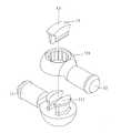
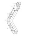
図4は、本発明の第1の実施形態を示す斜視図であり、図5は、この第1の実施形態を示す分解図である。(First embodiment)
FIG. 4 is a perspective view showing the first embodiment of the present invention, and FIG. 5 is an exploded view showing the first embodiment.
本発明の第1の実施形態は、図4及び図5に示されるように、第1の回転軸線L2に沿って延伸して円柱状に形成された連接柱21と、連接柱21の一端に連接柱21と一体に成形された球体状の第1の連結部22と、中空球体状に形成されて第1の連結部22を外から包む球体部237及び中空円柱状に形成されて連接柱21を外から包む円柱体部236を有しながら、第1の連結部22に対して第1の回転軸線L2を軸心として相対的に回動できるように第1の連結部22に取付けられている回動部材23と、回動部材23を更に外から包むことができるよう、中空の略球体状に形成されながら、回動部材23に対して第1の回転軸線L2と略直交する第2の回転軸線L3を軸心として相対的に回動できるように取付けられている第2の連結部24と、第2の連結部24に連接され、一端に挿入孔310が開けられているメス部材31が形成されている本体部材3と、連接柱21の前記一端の反対端に連接され、挿入孔310に挿し込んでメス部材31と係合できるオス部材4と、を有している組立関節2である。 As shown in FIGS. 4 and 5, the first embodiment of the present invention includes a connecting
この実施形態において、連接柱21はオス部材4と一体に成形され、第2の連結部24は本体部材3と一体に成形されている。 In this embodiment, the connecting
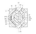
図6は、この第1の実施形態における回動部材23の分解斜視図であり、図7は、この第1の実施形態における回動部材23の正面図であり、図8は、図4におけるVIII−VIII線に沿う正面断面図であり、図9は、図4におけるIX−IX線に沿う側面断面図である。 FIG. 6 is an exploded perspective view of the rotating
図6〜図9に示されるように、連接柱21は、第1の連結部22から第2の連結部24外に延伸し、第1の連結部22の第1の回転軸線L2を軸心として回動できると共に第2の回転軸線L3を軸心として揺動することができる。 As shown in FIGS. 6 to 9, the connecting
第1の連結部22の表面には、互いに間を空け、且つ第1の回転軸線L2を囲むように並ぶ複数の第1の嵌合部221が凹陥するように形成されている。 A plurality of first
第2の連結部24は、その回動部材23に向かう内表面に互いに間を空け、且つ第2の回転軸線L3を囲むように並ぶ複数の第3の嵌合部242が凹陥するように形成されている。また、この第2の連結部24は、連接柱21及び回動部材23における連接柱21を外から包む円柱体部236が通過でき、且つ第1の連結部22及び回動部材23の第2の連結部24に対する第2の回転軸線L3を軸心とする回動において連接柱21及び円柱体部236の揺動に対応し、第2の回転軸線L3を囲むように延伸する穿設孔241が開けられ、そして、第2の回転軸線L3に沿って互いに反対の両側それぞれに設置孔243が開けられている。 The second connecting
回動部材23の球体部237は、図6に示されるように、中空に形成されて第1の連結部22を外から包む球状本体2371と、球状本体2371に取り付けられている2つの弾性プレート2372と、を有している。 As shown in FIG. 6, the
球状本体2371には、複数の第1の嵌合部221及び複数の第3の嵌合部242が配置される位置に対応し、且つ第2の回転軸線L3を囲む所定の周面に沿って延伸するように開けられる帯状孔2373が形成されている。 The spherical
弾性プレート2372は、それぞれ、帯状孔2373の2つの連接柱21に近い周縁から、前記所定の周面に沿って、互いに接触しないように連接柱21から離れた周縁へ延伸するように球状本体2371に取り付けられていると共に、球状本体2371に対する揺動で交互に第1の連結部22と第2の連結部24とに接近したり離間したりすることができるように形成されている。 Each of the
弾性プレート2372の第1の連結部22に向かう内表面には、それぞれ、向かい合う2つの第1の嵌合部221と凹凸嵌合できるように突出する上、第1の連結部22を第1の回転軸線L2を軸心として回動すると、嵌合していた第1の嵌合部221から離れて、その回動に応じて向かい合う位置に移動してきた他の第1の嵌合部221と嵌合することができる上、且つ第1の連結部22側へ付勢されている第2の嵌合部234が2つ形成されている。 The inner surface of the
更に、弾性プレート2372の第2の連結部24に向かう外表面には、それぞれ、向かい合う3つの第3の嵌合部242と凹凸嵌合できるように突出する上、回動部材23を第2の回転軸線L3を軸心として回動すると、嵌合していた第3の嵌合部242から離れて、その回動に応じて向かい合う位置に移動してきた他の第3の嵌合部242と嵌合することができる上、且つ第2の連結部24側へ付勢されている第4の嵌合部235が3つ形成されている。 Furthermore, the outer surface of the
即ち、弾性プレート2372は、第1の連結部22に向かう内表面に第1の嵌合部221と凹凸嵌合できる第2の嵌合部234が2つ形成され、第2の連結部24に向かう外表面に第3の嵌合部242と凹凸嵌合できる第4の嵌合部235が3つ形成されており、外表面側の第4の嵌合部235が第3の嵌合部242から離れると、内表面側の第2の嵌合部234が第1の嵌合部221に嵌まり込んで凹凸嵌合し、また、内表面側の第2の嵌合部234が第1の嵌合部221から離れると、外表面側の第4の嵌合部235が第3の嵌合部242に嵌まり込んで凹凸嵌合するように、第1の連結部22の第1の嵌合部221と、第2の連結部24の第3の嵌合部242と、の間で弾性的に揺動するように構成されている。 That is, the
また、図7に示されるように、2つの弾性プレート2372と球状本体2371との間には、第2の回転軸線L3を囲む2つの第1の隙間232が画成され、2つの弾性プレート2372の間には、2つの第1の隙間232と連通する第2の隙間233が画成されている。 As shown in FIG. 7, two
そして、回動部材23の外表面には、第2の回転軸線L3に沿って互いに反対の両方向へ突出して第2の連結部24の2つの設置孔243を挿通する2つの回転軸231が形成されている。 Then, two
本体部材3には、図4及び図5に示されるように、本体部材3を第1の回転軸線L2と略直交する方向に沿って貫通して、2つの第1の開口321及び第2の開口322を有する収容空間32が開けられている。 As shown in FIGS. 4 and 5, the
なお、連接柱21の前記一端の反対端及び第2の連結部24には、他のおもちゃを構成する部材、例えばメス部材、オス部材、関節部材、本体部材、などを形成または連接することができる。 Note that a member constituting another toy, for example, a female member, a male member, a joint member, a main body member, or the like may be formed or connected to the end opposite to the one end of the connecting
図10は、2つの上記第1の実施形態を互いに係合することを示す斜視図であり、図11は、上記第1の実施形態における組立関節2が回動された状態を示す斜視図である。 FIG. 10 is a perspective view showing that the two first embodiments are engaged with each other, and FIG. 11 is a perspective view showing a state where the
上記の構成によれば、本発明が有する組立関節2は、第1の回転軸線L2及び第2の回転軸線L3を軸心として回動でき、例えば、図10に示されるように、この実施形態2つを互いに係合して、そして、図10の左側の組立関節2の第1の連結部(図中に示されていない)を第1の回転軸線L2を軸心として回動して、2つの本体部材3の収容空間32の開口方向が互いに略直交する状態にすることができ、また、図11に示されるように、図11の左側の組立関節2の回動部材及び第1の連結部を第2の回転軸線L3を軸心として回動することにより、連接柱が穿設孔(図中に示されていない)に沿って揺動して、2つの本体部材3の延伸方向が互いに略直交する状態にすることもできる。 According to said structure, the
(第2の実施形態)
図12は、本発明の第2の実施形態を示す分解図である。(Second Embodiment)
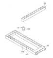
FIG. 12 is an exploded view showing a second embodiment of the present invention.
本発明の第2の実施形態は、上記第1の実施形態と類似する構成を有するので、ここでは詳しい説明を省略し、その相違点のみを説明する。 Since the second embodiment of the present invention has a configuration similar to that of the first embodiment, detailed description thereof will be omitted here, and only the differences will be described.
図12に示されるように、本発明の第2の実施形態は、回動部材23における2つの弾性プレート2372の第2の嵌合部234及び第4の嵌合部235が、それぞれ3つずつ形成され、そして、本体部材3の収容空間32が3つ形成され、そして、相隣する2つの収容空間32の開口方向が、互いに略直交している。それ以外、第1の実施形態と同じ構成を有する。 As shown in FIG. 12, the second embodiment of the present invention includes three second
この第2の実施形態の構成によれば、3つの収容空間32の開口方向により、より多くの姿勢で他の部材に連接できる。 According to the structure of this 2nd Embodiment, it can be connected with another member with more attitude | positions with the opening direction of the three
なお、第2の嵌合部234、第4の嵌合部235及び収容空間32の数は、本実施形態に限らず、必要に応じて適宜に設定できる。 In addition, the number of the 2nd
(第3の実施形態)
図13は、本発明の第3の実施形態を示す斜視図である。(Third embodiment)
FIG. 13 is a perspective view showing a third embodiment of the present invention.
本発明の第3の実施形態は、上記第1の実施形態と類似する構成を有するので、ここでは詳しい説明を省略し、その相違点のみを説明する。 Since the third embodiment of the present invention has a configuration similar to that of the first embodiment, detailed description thereof will be omitted here, and only the differences will be described.
本発明の第3の実施形態は、図13に示されるように、上記第1の実施形態の組立関節2、及び、上記第1の実施形態の本体部材3と、収容空間32に挿し込んで本体部材3に接続できる接続部材33とを有する接続装置を備える接続セット、並び接続部材33を本体部材3から取り外すことができる取外し道具5を有する組立セットである。 As shown in FIG. 13, the third embodiment of the present invention is inserted into the
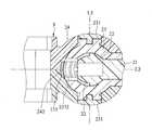
図14は、この第3の実施形態における接続部材33が本体部材3に係合された状態を示す断面図である。 FIG. 14 is a cross-sectional view showing a state in which the
接続部材33は、図13と図14に示されるように、基部331と、第1のフランジ部332と、第2のフランジ部333と、第1の挿入部334と、第2の挿入部335と、第1の係合突起336と、第2の係合突起337と、を有するように形成されている。 As shown in FIGS. 13 and 14, the connecting
基部331は、第1の延伸方向L4に沿って延伸するように柱状に形成されている。 The
第1のフランジ部332及び第2のフランジ部333は、基部331の両端それぞれから外側へ張り出し、互いに間を空けて、第1の延伸方向L4と直交する断面が非円形に形成されている。 The
第1の挿入部334及び第2の挿入部335は、基部331の前記両端からそれぞれ延伸して収容空間32に挿し込むことができ、且つ可撓性を有し、基部331に対して揺動できるように4つの板状のものとして形成されている。 The
第1の係合突起336及び第2の係合突起337それぞれは、第1の挿入部334の収容空間32に挿し込むことができる先端と第2の挿入部335の収容空間32に挿し込むことができる先端に形成されている。 Each of the
なお、第1の挿入部334及び第2の挿入部335は、上記ではそれぞれ4つの板状のものとして構成したが、数量はこれに限定されない。In addition, although the
本体部材3は、第1の開口321の端縁及び第2の開口322の端縁が第1のフランジ部332と第2のフランジ部333との非円形断面に対応して第1のフランジ部332と第2のフランジ部333とを受入れることができるように形成されていると共に、収容空間32内には、接続部材33の第1の挿入部334が収容空間32に挿し込まれる際に、第1の挿入部334が収容空間32に挿し込まれる方向における両端がそれぞれ第1のフランジ部332と第1の係合突起336とに当接して第1の挿入部334を係止することができる縮径部323が形成されている。また、接続部材33の第2の挿入部335が収容空間32に挿し込まれると、第2の挿入部335が収容空間32に挿し込まれる方向における縮径部323の両端が、それぞれ第2のフランジ部333と第2の係合突起337とに当接して第2の挿入部335を係止することができる。 The
この実施形態において、第1のフランジ部332と第2のフランジ部333とは、形及び大きさが同じ四角形に形成され、第1の開口321の端縁及び第2の開口322の端縁は、第1のフランジ部332及び第2のフランジ部333に対応して、形及び大きさが同じく四角形に形成されている。 In this embodiment, the
図15は、上記第3の実施形態における接続部材33で2つの本体部材3を接続することを示す斜視図である。 FIG. 15 is a perspective view showing that the two
上記の構成によれば、図15に示されるように、接続部材33の第1の挿入部334と第2の挿入部335それぞれを2つの本体部材3それぞれが有する収容空間32に挿し込むことにより、2つの本体部材3を接続できる。更に、第1のフランジ部332と第2のフランジ部333との第1の延伸方向L4と直交する断面が非円形に形成されているので、接続部材33が挿し込まれた本体部材3は、第1の延伸方向L4を軸心として回転することがなく、該回転により従来の両部材の間の係合姿勢を維持しにくいという欠点及び本体部材3が接続部材33から外れやすいという欠点を解消できる。 According to said structure, as FIG. 15 shows, by inserting each of the
取外し道具5は、図13に示されるように、手で操作しやすいように第2の延伸方向L5に沿って延伸して形成される把握部51と、第2の延伸方向L5と所定の角度を成す第3の延伸方向L6に沿って延伸するように形成されている上、接続部材33の基部331に対応して、第1のフランジ部332と第2のフランジ部333との間にある箇所を両側から挟むことができるように二股に分かれる2つの取外し突起521を有する挟持部52と、を有している。 As shown in FIG. 13, the
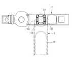
図16は、この第3の実施形態において取外し道具5を用いて接続部材33を本体部材3から取り外すことを示す上視図であり、図17は、この第3の実施形態において取外し道具5を用いて接続部材33を本体部材3から取り外すことを示す側面断面図であり、図18は、この第3の実施形態において取外し道具5を用いて接続部材33を本体部材3から取り外すことを示す側面断面図である。 FIG. 16 is a top view showing removal of the connecting
この取外し道具5の構成によれば、例えば、接続部材33の第1のフランジ部332が第1の開口321に嵌まり込むように接続部材33が本体部材3の収容空間32に挿し込まれて係合されている際、図16と図17に示されるように、2つの取外し突起521で基部331の両側を挟むことができる。そして、図17と図18に示されるように、挟持部52が第1の開口321の端縁に接触してその接触部分を支点として2つの取外し突起521が第2のフランジ部333に当接するように把握部51を揺動すると、2つの取外し突起521が第2のフランジ部333に対して、接続部材33を収容空間32に挿し込む方向の反対方向に向かう力を加えるによって、接続部材33を収容空間32から引き抜くことができる。 According to the configuration of the
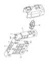
図19は、上記第3の実施形態における接続部材33を用いて本体部材3を他の部材と接続することを示す斜視図である。 FIG. 19 is a perspective view showing that the
なお、接続部材33は、本体部材3を他の収容空間32が開けられている部材と接続することもできる。例えば図19に示されるように、接続部材33を用いて本体部材3を、アーマーのような形に形成され、収容空間32が開けられている部材と接続することができる。 In addition, the
本発明の組立関節は、2つの部材を互いに可動的に接続する組立式のおもちゃに適用することができる。特に、多様な可動範囲が必要な組立式のおもちゃに適用することに好適である。 The assembly joint of the present invention can be applied to an assembly type toy in which two members are movably connected to each other. In particular, it is suitable for application to an assembling-type toy that requires various movable ranges.
L2 第1の回転軸線
L3 第2の回転軸線
2 組立関節
21 連接柱
22 第1の連結部
221 第1の嵌合部
23 回動部材
231 回転軸
232 第1の隙間
233 第2の隙間
234 第2の嵌合部
235 第4の嵌合部
236 円柱体部
237 球体部
2371 球状本体
2372 弾性プレート
2373 帯状孔
24 第2の連結部
241 穿設孔
242 第3の嵌合部
243 設置孔
3 本体部材
31 メス部材
310 挿入孔
32 収容空間
321 第1の開口
322 第2の開口
323 縮径部
33 接続部材
331 基部
332 第1のフランジ部
333 第2のフランジ部
334 第1の挿入部
335 第2の挿入部
336 第1の係合突起
337 第2の係合突起
4 オス部材
5 取外し道具
51 把握部
52 挟持部
521 取外し突起
L4 第1の延伸方向
L5 第2の延伸方向
L6 第3の延伸方向L2 First rotation axis L3
Claims (15)
Translated fromJapanese前記連接柱の一端に配置されている第1の連結部と、
中空に形成されて前記第1の連結部を外から包みながら、前記第1の連結部に対して前記第1の回転軸線を軸心として相対的に回動できるように前記第1の連結部に取付けられている回動部材と、
前記回動部材を更に外から包みながら、前記回動部材に対して前記第1の回転軸線と略直交する第2の回転軸線を軸心として相対的に回動できるように取付けられている第2の連結部と、を有していることを特徴とする組立関節。A connecting column extending along a predetermined first axis of rotation;
A first connecting portion disposed at one end of the connecting column;
The first connecting portion is formed in a hollow shape so that the first connecting portion can be rotated relative to the first connecting portion about the first rotation axis while wrapping the first connecting portion from the outside. A rotating member attached to the
The second rotation axis that is substantially orthogonal to the first rotation axis is attached to the rotation member so as to be relatively rotatable about the second rotation axis while wrapping the rotation member from the outside. And an assembling joint.
前記回動部材は、前記第1の連結部を外から包むことができるように、中空の略球体状に形成されており、
前記第2の連結部は、前記回動部材を外から包むことができるように、中空の略球体状に形成されていることを特徴とする請求項1に記載の組立関節。The first connecting portion is formed in a substantially spherical shape,
The rotating member is formed in a hollow, substantially spherical shape so as to wrap the first connecting portion from the outside,
2. The assembly joint according to claim 1, wherein the second connecting portion is formed in a hollow and substantially spherical shape so as to wrap the rotating member from the outside.
前記回動部材の前記第1の連結部に向かう内表面には、向かい合う少なくとも1つの前記第1の嵌合部と凹凸嵌合できる上、前記第1の連結部と前記回動部材とが前記第1の回転軸線を軸心として相対回動すると、嵌合していた前記第1の嵌合部から離れて、その回動に応じて向かい合う位置に移動してきた他の前記第1の嵌合部と嵌合することができる第2の嵌合部が少なくとも1つ形成されていることを特徴とする請求項1または請求項2に記載の組立関節。On the surface of the first connecting portion, a plurality of first fitting portions are formed so as to be spaced apart from each other and so as to surround the first rotation axis,
The inner surface of the rotating member that faces the first connecting portion can be concavo-convexly fitted with at least one of the first fitting portions facing each other, and the first connecting portion and the rotating member are When the relative rotation is performed with the first rotation axis as the axis, the other first fitting that has moved away from the first fitting portion that has been fitted and moved to a position facing it in accordance with the rotation. The assembly joint according to claim 1, wherein at least one second fitting portion that can be fitted to the portion is formed.
前記球状本体には、前記複数の第1の嵌合部が配置される位置に対応し且つ前記第2の回転軸線を囲む所定の周面に沿って延伸するように開けられる帯状孔が形成されており、
前記弾性プレートは、前記帯状孔の前記連接柱に近い周縁から、前記所定の周面に沿って前記連接柱から離れた周縁へ延伸するように前記球状本体に取り付けられていると共に、前記第2の嵌合部は、前記弾性プレートの前記第1の連結部に向かう内表面に形成されている上、前記第1の連結部側へ付勢されており、
この構成により、前記回動部材が前記第1の連結部に対して前記第1の回転軸線を軸心として相対回動すると、前記弾性プレートは、前記第2の嵌合部の嵌合していた前記第1の嵌合部から離れて、その回動に応じて向かい合う位置に移動してきた他の前記第1の嵌合部と嵌合する動きに対応して前記球状本体に対して揺動することができるようになっていることを特徴とする請求項3に記載の組立関節。The rotating member has a spherical body that is hollow and wraps the first connecting portion from the outside, and an elastic plate that is attached to the spherical body.
The spherical main body is formed with a band-shaped hole that corresponds to a position where the plurality of first fitting portions are disposed and is opened so as to extend along a predetermined peripheral surface surrounding the second rotation axis. And
The elastic plate is attached to the spherical body so as to extend from a peripheral edge of the belt-shaped hole close to the connecting column to a peripheral edge separated from the connecting column along the predetermined peripheral surface, and the second plate The fitting portion is formed on the inner surface of the elastic plate toward the first connection portion, and is biased toward the first connection portion.
With this configuration, when the rotating member rotates relative to the first connecting portion about the first rotation axis, the elastic plate is fitted to the second fitting portion. Further, it swings with respect to the spherical main body in response to the movement to be engaged with the other first fitting portion which has moved away from the first fitting portion and moved to a position facing the first fitting portion. The assembly joint according to claim 3, wherein the assembly joint can be made.
前記回動部材の前記第2の連結部に向かう外表面には、向かい合う少なくとも1つの前記第3の嵌合部と凹凸嵌合できる上、前記回動部材と前記第2の連結部とが前記第2の回転軸線を軸心として相対回動すると、嵌合していた前記第3の嵌合部から離れて、その回動に応じて向かい合う位置に移動してきた他の前記第3の嵌合部と嵌合することができる第4の嵌合部が少なくとも1つ形成されていることを特徴とする請求項1または請求項2に記載の組立関節。A plurality of third fitting portions are formed on the inner surface of the second connecting portion that faces the rotating member, and are arranged so as to be spaced apart from each other and surround the second rotation axis.
On the outer surface of the rotating member that faces the second connecting portion, at least one third fitting portion that faces the concave and convex portions can be fitted, and the rotating member and the second connecting portion are connected to each other. When the second rotation axis is rotated relative to the axis, the other third fitting is moved away from the fitted third fitting portion and moved to the opposite position in accordance with the rotation. The assembly joint according to claim 1, wherein at least one fourth fitting portion that can be fitted to the portion is formed.
前記球状本体には、前記複数の第3の嵌合部が配置される位置に対応し且つ前記第2の回転軸線を囲む所定の周面に沿って延伸するように開けられる帯状孔が形成されており、
前記弾性プレートは、前記帯状孔の前記連接柱に近い周縁から、前記所定の周面に沿って、前記連接柱から離れた周縁へ延伸するように前記球状本体に取り付けられていると共に、前記第4の嵌合部は、前記弾性プレートの前記第2の連結部に向かう外表面に形成されている上、前記第2の連結部側へ付勢されており、
この構成により、前記回動部材が前記第2の連結部に対して前記第2の回転軸線を軸心として相対回動すると、前記弾性プレートは、前記第3の嵌合部の嵌合していた前記第4の嵌合部から離れて、その回動に応じて向かい合う位置に移動してきた他の前記第4の嵌合部と嵌合する動きに対応して前記球状本体に対して揺動することができるようになっていることを特徴とする請求項5に記載の組立関節。The rotating member has a spherical body that is hollow and wraps the first connecting portion from the outside, and an elastic plate that is attached to the spherical body.
The spherical body is formed with a band-shaped hole that corresponds to a position where the plurality of third fitting portions are disposed and is opened so as to extend along a predetermined peripheral surface surrounding the second rotation axis. And
The elastic plate is attached to the spherical body so as to extend from the peripheral edge of the belt-shaped hole near the connecting column to the peripheral edge away from the connecting column along the predetermined peripheral surface. 4 is formed on the outer surface of the elastic plate toward the second connecting portion, and is biased toward the second connecting portion.
With this configuration, when the rotating member rotates relative to the second connecting portion about the second rotation axis, the elastic plate is fitted to the third fitting portion. Further, it swings with respect to the spherical main body in response to the movement to be engaged with the other fourth fitting portion which has moved away from the fourth fitting portion and moved to a position facing in accordance with the rotation of the fourth fitting portion. The assembly joint according to claim 5, wherein the assembly joint is configured to be able to perform the above operation.
前記帯状孔が沿って延伸する前記所定の周面は、前記複数の第1の嵌合部が配置される位置と、前記複数の第3の嵌合部が配置される位置と、に共に対応しており、
前記弾性プレートは、前記所定の周面に沿って延伸すると共に、前記第2の連結部に向かう外表面に、向かい合う少なくとも1つの前記第3の嵌合部と凹凸嵌合できる上、前記回動部材と前記第2の連結部とが前記第2の回転軸線を軸心として相対回動すると、嵌合していた前記第3の嵌合部から離れて、その回転に応じて向かい合う位置に移動してきた他の前記第3の嵌合部と嵌合することができる第4の嵌合部が少なくとも1つ形成されていることを特徴とする請求項4に記載の組立関節。A plurality of third fitting portions are formed on the inner surface of the second connecting portion that faces the rotating member, and are arranged so as to be spaced apart from each other and surround the second rotation axis.
The predetermined peripheral surface extending along the band-shaped hole corresponds to both a position where the plurality of first fitting portions are arranged and a position where the plurality of third fitting portions are arranged. And
The elastic plate extends along the predetermined peripheral surface, and can be concavo-convexly fitted with at least one third fitting portion facing the outer surface toward the second connecting portion, and can be rotated. When the member and the second connecting portion rotate relative to each other about the second rotation axis, the member moves away from the fitted third fitting portion and moves to a position facing each other according to the rotation. The assembly joint according to claim 4, wherein at least one fourth fitting portion that can be fitted with the other third fitting portion is formed.
前記連接柱は、前記第1の連結部から前記第2の連結部に形成される前記穿設孔を経由して前記第2の連結部外に延伸し、前記第1の連結部の前記第1の回転軸線を軸心として回動できると共に前記第2の回転軸線を軸心として揺動できることを特徴とする請求項1〜請求項7いずれか一項に記載の組立関節。The second connecting portion extends from the first connecting portion in the rotation of the first connecting portion and the rotating member with respect to the second connecting portion with respect to the second rotation axis. Corresponding to the swinging of the connecting column, a drilling hole extending so as to surround the second rotation axis is formed,
The connecting column extends from the first connecting portion to the outside of the second connecting portion through the drilled hole formed in the second connecting portion, and the first connecting portion includes the first connecting portion. The assembly joint according to any one of claims 1 to 7, wherein the assembly joint is capable of rotating about one rotation axis as an axis and swinging about the second rotation axis.
前記接続部材は、所定の第1の延伸方向に沿って延伸するように形成される柱状の基部と、前記基部の一端から外側へ張り出し、前記第1の延伸方向と直交する断面が非円形になっている第1のフランジ部と、前記基部の前記一端から更に延伸して前記収容空間に挿し込むことができ、且つ可撓性を有し、前記基部に対して揺動できるように形成される第1の挿入部と、前記第1の挿入部の前記収容空間に挿し込むことができる先端に形成される第1の係合突起と、を有するように形成されており、
前記本体部材は、前記第1の開口の端縁が前記第1のフランジ部の非円形断面に対応して前記第1のフランジ部を受入れることができるように形成されていると共に、前記収容空間内に、前記接続部材の前記第1の挿入部が前記収容空間に挿し込まれる際に、前記第1の挿入部が前記収容空間に挿し込まれる方向における両端がそれぞれ前記第1のフランジ部と前記第1の係合突起とに当接して前記第1の挿入部を係止することができる縮径部が形成されていることを特徴とする接続セット。The assembly joint according to any one of claims 1 to 9, a main body member in which a housing space having a first opening is opened, and a connection that can be inserted into the housing space and connected to the main body member A connection set comprising a connection device having a member,
The connecting member has a columnar base formed so as to extend along a predetermined first extending direction, and projects outward from one end of the base, and a cross section orthogonal to the first extending direction is non-circular The first flange portion and the base portion are further extended from the one end of the base portion so as to be inserted into the housing space, and have flexibility and swing with respect to the base portion. And a first engaging protrusion formed at a tip that can be inserted into the accommodation space of the first insertion portion, and
The main body member is formed so that an edge of the first opening can receive the first flange portion corresponding to a non-circular cross section of the first flange portion, and the accommodating space. Inside, when the 1st insertion part of the connecting member is inserted in the accommodation space, both ends in the direction in which the 1st insertion part is inserted in the accommodation space are the first flange part, respectively. A connection set, characterized in that a reduced-diameter portion capable of abutting on the first engagement protrusion and locking the first insertion portion is formed.
前記接続部材の前記第2の挿入部が前記第2の開口を経由して前記収容空間に挿し込まれる際に、前記第2の挿入部が前記収容空間に挿し込まれる方向における前記縮径部の両端が、それぞれ前記第2のフランジ部と前記第2の係合突起とに当接して前記第2の挿入部を係止することができることを特徴とする請求項12または請求項13に記載の接続セット。The main body member has a second opening on the opposite side of the first opening so as to communicate with the accommodation space, and an end edge of the second opening is the second flange portion. Is formed so as to be able to receive the second flange portion corresponding to the non-circular cross section of
The reduced diameter portion in a direction in which the second insertion portion is inserted into the accommodation space when the second insertion portion of the connection member is inserted into the accommodation space via the second opening. The both ends of each can contact | abut to the said 2nd flange part and the said 2nd engaging protrusion, respectively, and can latch the said 2nd insertion part, The Claim 12 or Claim 13 characterized by the above-mentioned. Connection set.
前記取外し道具は、
手で操作しやすいように所定の延伸方向に沿って延伸して形成される把握部と、
前記接続部材の前記基部に対応して、前記第1のフランジ部と前記第2のフランジ部との間にある箇所を両側から挟むことができるように二股に分かれる2つの取外し突起を有する挟持部と、を有し、
前記接続部材の前記第1のフランジ部が前記第1の開口に嵌まり込むように前記接続部材が前記本体部材の前記収容空間に挿し込まれて係合されている際、前記2つの取外し突起が前記基部の両側を挟むことができ、前記挟持部が前記第1の開口の端縁に接触してその接触部分を支点として前記2つの取外し突起が前記第2のフランジ部に当接するように前記把握部を揺動すると、前記2つの取外し突起が前記第2のフランジ部に対して、前記接続部材が前記収容空間に挿し込まれる方向の反対方向に向かう力を加えるによって、前記接続部材を前記収容空間から引き抜くことができることを特徴とする組立セット。An assembly set comprising the connection set according to any one of claims 12 to 14, and a removal tool capable of removing the connection member of the connection set from the main body member,
The removal tool is:
A grasping portion formed by stretching along a predetermined stretching direction so that it can be easily operated by hand;
Corresponding to the base portion of the connecting member, a sandwiching portion having two removal projections that are divided into two forks so that a portion between the first flange portion and the second flange portion can be sandwiched from both sides And having
When the connection member is inserted and engaged in the housing space of the main body member so that the first flange portion of the connection member is fitted into the first opening, the two removal protrusions Can sandwich both sides of the base so that the clamping part contacts the edge of the first opening and the two removal projections abut against the second flange part with the contact part as a fulcrum. When the grasping portion is swung, the two removal protrusions apply a force to the second flange portion in a direction opposite to the direction in which the connection member is inserted into the accommodating space, thereby The assembly set can be pulled out from the housing space.
Applications Claiming Priority (2)
| Application Number | Priority Date | Filing Date | Title |
|---|---|---|---|
| TW103138061 | 2014-11-03 | ||
| TW103138061ATWI531732B (en) | 2014-11-03 | 2014-11-03 | Joint, the joint having a gripping means, and combinations thereof |
Publications (1)
| Publication Number | Publication Date |
|---|---|
| JP2016087409Atrue JP2016087409A (en) | 2016-05-23 |
Family
ID=53191468
Family Applications (1)
| Application Number | Title | Priority Date | Filing Date |
|---|---|---|---|
| JP2015033724APendingJP2016087409A (en) | 2014-11-03 | 2015-02-24 | Joint assembly, connection set including the joint assembly, and assembly set including the connection set |
Country Status (4)
| Country | Link |
|---|---|
| US (1) | US20160123360A1 (en) |
| EP (1) | EP3015149A3 (en) |
| JP (1) | JP2016087409A (en) |
| TW (1) | TWI531732B (en) |
Cited By (2)
| Publication number | Priority date | Publication date | Assignee | Title |
|---|---|---|---|---|
| JP2019072250A (en)* | 2017-10-17 | 2019-05-16 | 株式会社タカラトミー | Toy component removal structure |
| WO2022249777A1 (en)* | 2021-05-28 | 2022-12-01 | 株式会社バンダイ | Model component and joint structure |
Families Citing this family (4)
| Publication number | Priority date | Publication date | Assignee | Title |
|---|---|---|---|---|
| CN207871542U (en)* | 2017-12-06 | 2018-09-18 | 变形立方产品设计有限公司 | Building block monomer and building block assembly |
| US11794124B2 (en)* | 2018-10-02 | 2023-10-24 | Snap Ships LLC | Connection systems for toy construction pieces, toy construction pieces including the same, and toy construction kits including the same |
| CN113027898A (en)* | 2019-12-09 | 2021-06-25 | 何天斌 | Node connecting piece and node connecting assembly |
| DE102021102576A1 (en) | 2021-02-04 | 2022-08-04 | Airbus Operations Gmbh | Articulated connector for connecting several components |
Citations (3)
| Publication number | Priority date | Publication date | Assignee | Title |
|---|---|---|---|---|
| JPH0249682A (en)* | 1988-08-11 | 1990-02-20 | Takara Co Ltd | Two-member movable connection structure in toys |
| US20070281582A1 (en)* | 2003-12-15 | 2007-12-06 | Annette Himstedt | Doll Joint |
| JP3184234U (en)* | 2013-04-01 | 2013-06-20 | 有限会社ダイスプロジェクト | Doll toy movable connecting member and doll toy |
Family Cites Families (5)
| Publication number | Priority date | Publication date | Assignee | Title |
|---|---|---|---|---|
| US892105A (en)* | 1907-12-18 | 1908-06-30 | Edwin A Rives | Combined pipe support and clamp. |
| US2855232A (en)* | 1957-06-19 | 1958-10-07 | Gen Motors Corp | Resiliently mounted ball joint |
| JPS6138315U (en)* | 1984-08-13 | 1986-03-10 | 株式会社 ニフコ | ball joint |
| DE3530633A1 (en)* | 1985-08-28 | 1987-03-05 | Trw Ehrenreich Gmbh | BALL JOINT |
| US5704727A (en)* | 1995-10-31 | 1998-01-06 | Dana Corporation | Ball and socket joint assembly with self-centering retainer ring |
- 2014
- 2014-11-03TWTW103138061Apatent/TWI531732B/ennot_activeIP Right Cessation
- 2015
- 2015-02-24JPJP2015033724Apatent/JP2016087409A/enactivePending
- 2015-03-31USUS14/674,162patent/US20160123360A1/ennot_activeAbandoned
- 2015-04-21EPEP15164495.2Apatent/EP3015149A3/ennot_activeWithdrawn
Patent Citations (3)
| Publication number | Priority date | Publication date | Assignee | Title |
|---|---|---|---|---|
| JPH0249682A (en)* | 1988-08-11 | 1990-02-20 | Takara Co Ltd | Two-member movable connection structure in toys |
| US20070281582A1 (en)* | 2003-12-15 | 2007-12-06 | Annette Himstedt | Doll Joint |
| JP3184234U (en)* | 2013-04-01 | 2013-06-20 | 有限会社ダイスプロジェクト | Doll toy movable connecting member and doll toy |
Cited By (4)
| Publication number | Priority date | Publication date | Assignee | Title |
|---|---|---|---|---|
| JP2019072250A (en)* | 2017-10-17 | 2019-05-16 | 株式会社タカラトミー | Toy component removal structure |
| WO2022249777A1 (en)* | 2021-05-28 | 2022-12-01 | 株式会社バンダイ | Model component and joint structure |
| JP2022182793A (en)* | 2021-05-28 | 2022-12-08 | 株式会社バンダイ | Model parts and joint structures |
| JP7198871B2 (en) | 2021-05-28 | 2023-01-04 | 株式会社バンダイ | Model parts and joint structures |
Also Published As
| Publication number | Publication date |
|---|---|
| EP3015149A3 (en) | 2016-06-15 |
| TW201617533A (en) | 2016-05-16 |
| EP3015149A2 (en) | 2016-05-04 |
| US20160123360A1 (en) | 2016-05-05 |
| TWI531732B (en) | 2016-05-01 |
Similar Documents
| Publication | Publication Date | Title |
|---|---|---|
| JP2016087409A (en) | Joint assembly, connection set including the joint assembly, and assembly set including the connection set | |
| US8333526B2 (en) | Three degree of freedom universal joint | |
| US7670077B2 (en) | Rotatable joint and connecting device used for the same | |
| CN101871485B (en) | hinge structure | |
| KR102224027B1 (en) | Male connector and connection system for cooling pipe | |
| JP2015502181A5 (en) | ||
| JP5930501B2 (en) | Engaging device, and engaging device set including the engaging device and a tool for removing the engaging device | |
| CA2914943C (en) | Coupling device | |
| TWI725573B (en) | Flex-head tool | |
| CN105927661B (en) | Joint for climbing frame | |
| US7409817B1 (en) | Bicycle chain splitter | |
| JP3140838U (en) | Hinge structure | |
| JP5969535B2 (en) | model | |
| US20110051429A1 (en) | Table lamp and rotary joint thereof | |
| TW201910067A (en) | Drive tool with universal twist structure | |
| JP2010261590A (en) | Fluid pipe coupling device | |
| US20120103126A1 (en) | Joint mechanism for robot | |
| WO2010001740A1 (en) | Construction blocks | |
| KR101890668B1 (en) | Block connector | |
| WO2018220875A1 (en) | Assembly set | |
| TWM449665U (en) | Structure of universal joint | |
| CN104019121B (en) | Universal joint | |
| CN211912729U (en) | Combination components | |
| JP6981396B2 (en) | Pushbutton switch | |
| JP2012149731A (en) | Cabinet linking member |
Legal Events
| Date | Code | Title | Description |
|---|---|---|---|
| A131 | Notification of reasons for refusal | Free format text:JAPANESE INTERMEDIATE CODE: A131 Effective date:20160509 | |
| A02 | Decision of refusal | Free format text:JAPANESE INTERMEDIATE CODE: A02 Effective date:20170306 |