JP2016085430A - Virtual image display device - Google Patents
Virtual image display deviceDownload PDFInfo
- Publication number
- JP2016085430A JP2016085430AJP2014220043AJP2014220043AJP2016085430AJP 2016085430 AJP2016085430 AJP 2016085430AJP 2014220043 AJP2014220043 AJP 2014220043AJP 2014220043 AJP2014220043 AJP 2014220043AJP 2016085430 AJP2016085430 AJP 2016085430A
- Authority
- JP
- Japan
- Prior art keywords
- light
- incident
- diffraction grating
- light guide
- exit
- Prior art date
- Legal status (The legal status is an assumption and is not a legal conclusion. Google has not performed a legal analysis and makes no representation as to the accuracy of the status listed.)
- Withdrawn
Links
- 238000002834transmittanceMethods0.000claimsdescription6
- 230000015556catabolic processEffects0.000abstractdescription6
- 238000006731degradation reactionMethods0.000abstractdescription6
- 239000012780transparent materialSubstances0.000abstract4
- 230000003287optical effectEffects0.000description34
- 238000010586diagramMethods0.000description16
- 230000000694effectsEffects0.000description11
- 230000008859changeEffects0.000description10
- 230000005540biological transmissionEffects0.000description8
- 230000007423decreaseEffects0.000description5
- 239000011521glassSubstances0.000description5
- 230000004048modificationEffects0.000description4
- 238000012986modificationMethods0.000description4
- 230000009466transformationEffects0.000description4
- 230000004907fluxEffects0.000description3
- 238000000034methodMethods0.000description3
- 230000008569processEffects0.000description3
- 239000011347resinSubstances0.000description3
- 229920005989resinPolymers0.000description3
- 230000006866deteriorationEffects0.000description2
- 230000002238attenuated effectEffects0.000description1
- 239000003086colorantSubstances0.000description1
- 239000005329float glassSubstances0.000description1
- 239000003292glueSubstances0.000description1
- 239000004973liquid crystal related substanceSubstances0.000description1
- 238000004519manufacturing processMethods0.000description1
- QSHDDOUJBYECFT-UHFFFAOYSA-NmercuryChemical compound[Hg]QSHDDOUJBYECFT-UHFFFAOYSA-N0.000description1
- 229910052753mercuryInorganic materials0.000description1
- 239000007787solidSubstances0.000description1
- 238000011144upstream manufacturingMethods0.000description1
Images


Classifications
- G—PHYSICS
- G02—OPTICS
- G02B—OPTICAL ELEMENTS, SYSTEMS OR APPARATUS
- G02B27/00—Optical systems or apparatus not provided for by any of the groups G02B1/00 - G02B26/00, G02B30/00
- G02B27/01—Head-up displays
- G02B27/0101—Head-up displays characterised by optical features
- G—PHYSICS
- G02—OPTICS
- G02B—OPTICAL ELEMENTS, SYSTEMS OR APPARATUS
- G02B27/00—Optical systems or apparatus not provided for by any of the groups G02B1/00 - G02B26/00, G02B30/00
- G02B27/0025—Optical systems or apparatus not provided for by any of the groups G02B1/00 - G02B26/00, G02B30/00 for optical correction, e.g. distorsion, aberration
- G02B27/0037—Optical systems or apparatus not provided for by any of the groups G02B1/00 - G02B26/00, G02B30/00 for optical correction, e.g. distorsion, aberration with diffracting elements
- G—PHYSICS
- G02—OPTICS
- G02B—OPTICAL ELEMENTS, SYSTEMS OR APPARATUS
- G02B27/00—Optical systems or apparatus not provided for by any of the groups G02B1/00 - G02B26/00, G02B30/00
- G02B27/01—Head-up displays
- G02B27/0101—Head-up displays characterised by optical features
- G02B2027/011—Head-up displays characterised by optical features comprising device for correcting geometrical aberrations, distortion
- G—PHYSICS
- G02—OPTICS
- G02B—OPTICAL ELEMENTS, SYSTEMS OR APPARATUS
- G02B6/00—Light guides; Structural details of arrangements comprising light guides and other optical elements, e.g. couplings
- G02B6/0001—Light guides; Structural details of arrangements comprising light guides and other optical elements, e.g. couplings specially adapted for lighting devices or systems
- G02B6/0011—Light guides; Structural details of arrangements comprising light guides and other optical elements, e.g. couplings specially adapted for lighting devices or systems the light guides being planar or of plate-like form
- G02B6/0013—Means for improving the coupling-in of light from the light source into the light guide
- G02B6/0023—Means for improving the coupling-in of light from the light source into the light guide provided by one optical element, or plurality thereof, placed between the light guide and the light source, or around the light source
- G—PHYSICS
- G02—OPTICS
- G02B—OPTICAL ELEMENTS, SYSTEMS OR APPARATUS
- G02B6/00—Light guides; Structural details of arrangements comprising light guides and other optical elements, e.g. couplings
- G02B6/0001—Light guides; Structural details of arrangements comprising light guides and other optical elements, e.g. couplings specially adapted for lighting devices or systems
- G02B6/0011—Light guides; Structural details of arrangements comprising light guides and other optical elements, e.g. couplings specially adapted for lighting devices or systems the light guides being planar or of plate-like form
- G02B6/0033—Means for improving the coupling-out of light from the light guide
- G02B6/005—Means for improving the coupling-out of light from the light guide provided by one optical element, or plurality thereof, placed on the light output side of the light guide
- G—PHYSICS
- G02—OPTICS
- G02B—OPTICAL ELEMENTS, SYSTEMS OR APPARATUS
- G02B6/00—Light guides; Structural details of arrangements comprising light guides and other optical elements, e.g. couplings
- G02B6/24—Coupling light guides
- G02B6/26—Optical coupling means
- G02B6/34—Optical coupling means utilising prism or grating
Landscapes
- Physics & Mathematics (AREA)
- General Physics & Mathematics (AREA)
- Optics & Photonics (AREA)
- Diffracting Gratings Or Hologram Optical Elements (AREA)
- Instrument Panels (AREA)
Abstract
Description
Translated fromJapanese本発明は、虚像表示装置に関する。 The present invention relates to a virtual image display device.
従来、ビデオプロジェクターから投射された画像を虚像として視認させるフラットパネルプロジェクションディスプレイが知られている(例えば、特許文献1参照)。
この特許文献1に記載のプロジェクションディスプレイは、透明ロッド及び透明スラブと、ビデオプロジェクターと、2つのミラーと、を有する。
透明スラブは、屈折率が選択されたのりによって積層された複数のフロートガラスが研磨されて立方体スラブとなった構造を有し、のりとガラスとの間に形成される界面が、水平に対して45°となるように配置される。透明ロッドは、上記透明スラブと同様に形成されるが、当該ロッドは、透明スラブの厚み寸法に対応する略方形の断面を有する。ビデオプロジェクターは、上記2つのミラーを介して、上記透明ロッドのロッド軸に対して平行とはならない角度にて、画像を形成する光線を透明ロッドに出射する。2. Description of the Related Art Conventionally, a flat panel projection display that visually recognizes an image projected from a video projector as a virtual image is known (see, for example, Patent Document 1).
The projection display described in
A transparent slab has a structure in which a plurality of float glasses laminated by a paste having a refractive index selected are polished to form a cubic slab, and the interface formed between the paste and the glass is horizontal. It arrange | positions so that it may become 45 degrees. The transparent rod is formed in the same manner as the transparent slab, but the rod has a substantially square cross section corresponding to the thickness dimension of the transparent slab. The video projector emits a light beam that forms an image to the transparent rod through the two mirrors at an angle that is not parallel to the rod axis of the transparent rod.
このようなプロジェクションディスプレイでは、透明ロッド内に入射された光線は、当該透明ロッド内をロッド軸に沿って進行する。そして、内部を進行する光線は、のりとガラスとの界面にて部分的に反射されて垂直方向に外部に出射され、これにより、透明ロッドから透明スラブ内に入射される。また、透明スラブ内に入射された光線は、透明ロッドと同様に、それぞれの上記界面にて部分的に反射され、当該透明スラブにおける各界面に応じた位置から水平方向に光線が出射される。そして、当該光線の進行方向に観察者が位置することで、当該光線により形成される画像を観察可能となる。すなわち、ビデオプロジェクターにより出射された光線の出射位置は、透明ロッドにより垂直方向に広げられ、透明スラブにより水平方向に広げられる。
このようなプロジェクションディスプレイは、例えば、ヘッドアップディスプレイに適用される。In such a projection display, the light beam incident on the transparent rod travels along the rod axis in the transparent rod. Then, the light beam traveling inside is partially reflected at the interface between the glue and the glass and is emitted to the outside in the vertical direction, so that it enters the transparent slab from the transparent rod. Similarly to the transparent rod, the light beam incident on the transparent slab is partially reflected at each of the interfaces, and the light beam is emitted in a horizontal direction from a position corresponding to each interface in the transparent slab. Then, when an observer is positioned in the traveling direction of the light beam, an image formed by the light beam can be observed. That is, the emission position of the light beam emitted by the video projector is expanded in the vertical direction by the transparent rod, and is expanded in the horizontal direction by the transparent slab.
Such a projection display is applied to a head-up display, for example.
上記特許文献1に記載のプロジェクションディスプレイは、例えばヘッドアップディスプレイに適用された場合のように、観察位置が固定されて、虚像である表示画像にのみピントが合う用途に用いられる場合には問題ない。
しかしながら、上記透明スラブの構成では、上記界面にて一部の光が反射されて観察者の眼に届くため、任意の観察位置から当該表示画像が観察される用途では、透明スラブの存在が認識されやすく、界面の存在及び界面間の隙間が表示画像に重畳されて、ノイズとなって認識されやすいという問題がある。The projection display described in
However, in the configuration of the transparent slab, part of the light is reflected at the interface and reaches the observer's eyes. Therefore, in applications where the display image is observed from an arbitrary observation position, the presence of the transparent slab is recognized. There is a problem that the presence of the interface and the gap between the interfaces are superimposed on the display image and are easily recognized as noise.
具体的に、上記透明スラブでは、上記界面での反射が生じるごとに、当該界面を介して出射される光線全体の輝度が低下する。このため、透明スラブ内での光線の進行方向における上流側の界面にて反射される光線の輝度と、下流側の界面にて反射される光線の輝度とが異なる。このような輝度の相違により、各界面の存在及び界面間の隙間が視認されやすくなり、ひいては、透明スラブ越しに観察される画像が劣化するという問題がある。
このような問題から、画像の劣化を抑制できる他の構成が要望されてきた。Specifically, in the transparent slab, every time reflection occurs at the interface, the brightness of the entire light beam emitted through the interface decreases. For this reason, the brightness | luminance of the light ray reflected in the upstream interface in the advancing direction of the light ray in a transparent slab differs from the brightness | luminance of the light ray reflected in a downstream interface. Due to such a difference in brightness, the presence of each interface and the gap between the interfaces are easily visible, and as a result, there is a problem that an image observed through the transparent slab deteriorates.
Due to such problems, there has been a demand for another configuration capable of suppressing image degradation.
本発明は、画像の劣化を抑制できる虚像表示装置を提供することを目的の1つとする。 An object of the present invention is to provide a virtual image display device capable of suppressing image degradation.
本発明の一態様に係る虚像表示装置は、第1入射面を介して内部に入射される表示光束を繰り返し内面反射させて、前記第1入射面から離れる第1方向側に進行させるとともに、外部との界面の少なくとも1つの面であって前記第1方向に延びる第1出射面のそれぞれの領域から前記表示光束の一部の光を外部に出射する第1導光体と、入射される光を回折して前記第1導光体内に入射させる第1入射側回折格子と、前記第1導光体から入射される光を回折する第1出射側回折格子と、を備えることを特徴とする。 In the virtual image display device according to one aspect of the present invention, the display light beam incident on the inside through the first incident surface is repeatedly reflected on the inner surface to travel toward the first direction away from the first incident surface, and to the outside. A first light guide that emits part of the light beam of the display light beam from each region of the first emission surface that extends in the first direction, and the incident light. A first incident-side diffraction grating that diffracts the light incident on the first light guide and a first emission-side diffraction grating that diffracts the light incident from the first light guide. .
なお、第1入射側回折格子は、第1入射面と対向する位置に配置されてもよく、当該第1入射面とは反対側の第1導光体の面と対向する位置(第1導光体を挟んで第1入射面と対向する位置)に配置されてもよい。
前者の場合には、第1入射側回折格子は、透過型回折格子により構成でき、当該第1入射側回折格子により回折された表示光束は、第1入射面を介して第1導光体内に入射され、当該第1導光体内を進行する。すなわち、第1入射側回折格子は、入射される光を回折して、前記第1入射面を介して前記第1導光体内に入射させる透過型回折格子となる。
後者の場合には、第1入射側回折格子は、反射型回折格子により構成でき、第1入射面から第1導光体内に入射された表示光束は、第1入射側回折格子に入射されて回折され、第1導光体内を進行する。すなわち、第1入射側回折格子は、第1導光体から入射される光を回折して第1導光体内に入射させる反射型回折格子となる。The first incident-side diffraction grating may be arranged at a position facing the first incident surface, and a position facing the surface of the first light guide on the side opposite to the first incident surface (first guide). It may be arranged at a position facing the first incident surface across the light body.
In the former case, the first incident-side diffraction grating can be constituted by a transmissive diffraction grating, and the display light beam diffracted by the first incident-side diffraction grating is passed through the first incident surface into the first light guide. Incident light travels through the first light guide. That is, the first incident-side diffraction grating is a transmissive diffraction grating that diffracts incident light and enters the first light guide through the first incident surface.
In the latter case, the first incident side diffraction grating can be constituted by a reflection type diffraction grating, and the display light beam incident on the first light guide from the first incident surface is incident on the first incident side diffraction grating. Diffracted and travels through the first light guide. In other words, the first incident-side diffraction grating is a reflective diffraction grating that diffracts the light incident from the first light guide and enters the first light guide.
また、第1出射側回折格子も同様に、第1出射面と対向する位置に配置されてもよく、当該第1出射面とは反対側の第1導光体の面と対向する位置(第1導光体を挟んで第1入射面と対向する位置)に配置されてもよい。
前者の場合には、第1出射側回折格子は、透過型回折格子により構成でき、当該第1出射面から出射された表示光束は、第1出射側回折格子により回折されて、虚像表示装置の外部に出射される。すなわち、第1出射側回折格子は、第1出射面から入射される光を回折して、虚像表示装置の外部に出射する透過型回折格子となる。
後者の場合には、第1出射側回折格子は、反射型回折格子により構成でき、第1導光体内を上記第1方向に進行しつつ第1出射側回折格子に入射された表示光束は、当該第1出射側回折格子により回折されて、第1出射面から第1導光体の外部、すなわち、虚像表示装置の外部に出射される。すなわち、第1出射側回折格子は、第1導光体から入射される光を回折して、回折された光が第1出射面を介して外部に出射される方向に進行させる反射型回折格子となる。Similarly, the first exit-side diffraction grating may be disposed at a position facing the first exit surface, and a position facing the surface of the first light guide opposite to the first exit surface (first It may be arranged at a position facing the first incident surface across one light guide.
In the former case, the first exit-side diffraction grating can be constituted by a transmissive diffraction grating, and the display light beam emitted from the first exit surface is diffracted by the first exit-side diffraction grating, and the virtual image display device It is emitted to the outside. That is, the first emission side diffraction grating is a transmission type diffraction grating that diffracts the light incident from the first emission surface and emits the light to the outside of the virtual image display device.
In the latter case, the first exit-side diffraction grating can be constituted by a reflection-type diffraction grating, and the display light beam incident on the first exit-side diffraction grating while traveling in the first direction within the first light guide is The light is diffracted by the first emission side diffraction grating and emitted from the first emission surface to the outside of the first light guide, that is, to the outside of the virtual image display device. In other words, the first output-side diffraction grating diffracts the light incident from the first light guide and causes the diffracted light to travel to the outside through the first output surface. It becomes.
ここで、回折格子は、入射される光の波長が大きいほど回折角(入射光と回折格子の法線とのなす角)が大きい。このため、第1入射側回折格子は、入射される表示光束を構成する光を、それぞれの波長毎に異なる回折角で回折する。これにより、それぞれ波長が異なる光は、それぞれ異なる領域にて内面反射を繰り返しつつ第1導光体内を第1方向側に進行する。一方、第1出射側回折格子は、第1導光体から入射される光を、波長毎に異なる回折角にて回折する。このような虚像表示装置から出射される光が入射される位置に観察者が位置すれば、当該光により形成される画像を虚像として観察できる。この際、第1導光体を第1方向に長く形成し、当該第1方向に長い第1出射側回折格子を第1導光体に設けることにより、第1方向における任意の位置で、入射された表示光束により形成される画像を、第1導光体の奥側(光の出射側とは反対側)に位置する虚像として視認できる。 Here, the diffraction grating has a larger diffraction angle (angle formed between the incident light and the normal line of the diffraction grating) as the wavelength of incident light is larger. For this reason, the first incident-side diffraction grating diffracts the light constituting the incident display light beam at a different diffraction angle for each wavelength. Accordingly, light having different wavelengths travels in the first direction in the first light guide while repeating internal reflection in different regions. On the other hand, the first exit-side diffraction grating diffracts the light incident from the first light guide at a different diffraction angle for each wavelength. If an observer is located at a position where light emitted from such a virtual image display device is incident, an image formed by the light can be observed as a virtual image. At this time, the first light guide is formed long in the first direction, and the first emission-side diffraction grating long in the first direction is provided in the first light guide, so that the light is incident at an arbitrary position in the first direction. The image formed by the displayed display light beam can be visually recognized as a virtual image located on the back side (the side opposite to the light emission side) of the first light guide.
このような虚像表示装置では、第1入射側回折格子による光の回折角が波長によって異なることにより、それぞれの波長の光が第1導光体内を異なる光路にて進行する。また、表示光束を第1入射側回折格子に集約して入射させれば、当該表示光束による画像の一部を形成する光と、他の一部を形成する光とで、第1導光体内を進行する際の光路を異ならせることができる。そして、第1導光体内を進行する光が、当該第1導光体内を進行する過程にて、又は、第1出射面から出射された後にて第1出射側回折格子を介することにより、波長毎に異なる回折角で回折されるので、当該光を虚像表示装置の外部に分散して出射させることができる他、当該光の出射角を波長毎に調整できる。
このような虚像表示装置によれば、第1方向に対して傾斜する複数の半透過層が内部に形成された導光体(例えば、上記透明スラブ)に表示光束を入射させ、それぞれの半透過層によって反射された光を出射する構成を採用した場合に生じる輝度変化の発生を抑制できる。従って、当該輝度変化が視認されて、出射される光によって形成される画像が劣化することを抑制できる。In such a virtual image display device, the diffraction angle of the light by the first incident side diffraction grating differs depending on the wavelength, so that the light of each wavelength travels in the first light guide through different optical paths. Further, if the display light beam is incident on the first incident side diffraction grating in a concentrated manner, the first light guide body is composed of light that forms part of the image by the display light beam and light that forms the other part. The optical path when traveling can be made different. Then, the light traveling in the first light guide passes through the first exit-side diffraction grating in the process of traveling through the first light guide or after being emitted from the first exit surface. Since each light is diffracted at a different diffraction angle, the light can be dispersed and emitted to the outside of the virtual image display device, and the emission angle of the light can be adjusted for each wavelength.
According to such a virtual image display device, a display light beam is incident on a light guide (for example, the transparent slab) in which a plurality of semi-transmissive layers inclined with respect to the first direction are formed. Generation | occurrence | production of the luminance change which arises when the structure which radiate | emits the light reflected by the layer is employ | adopted can be suppressed. Accordingly, it is possible to suppress degradation of the image formed by the emitted light when the luminance change is visually recognized.
上記一態様では、前記第1入射側回折格子と、前記第1出射側回折格子とは、それぞれ同じ波長の光が入射された際の回折角が同じであることが好ましい。
上記一態様によれば、第1入射側回折格子に入射された光が出射される際の回折角と、第1出射側回折格子に入射された光が出射される際の回折角とは、当該光の波長毎にそれぞれ同じとなる。これによれば、第1入射側回折格子への光の入射角(第1入射側回折格子の光入射面の法線に対する入射光の角度)と、第1出射側回折格子からの当該光の出射角(第1出射側回折格子の光出射面の法線に対する出射光の角度)とを、同じ角度にすることができる。従って、虚像表示装置からの光の出射角を容易に調整できる他、当該光によって形成される画像を観察者が視認しやすくすることができる。In the above aspect, it is preferable that the first incident-side diffraction grating and the first emission-side diffraction grating have the same diffraction angle when light having the same wavelength is incident thereon.
According to the above aspect, the diffraction angle when the light incident on the first incident-side diffraction grating is emitted and the diffraction angle when the light incident on the first output-side diffraction grating is emitted are: It becomes the same for each wavelength of the light. According to this, the incident angle of the light to the first incident side diffraction grating (the angle of the incident light with respect to the normal of the light incident surface of the first incident side diffraction grating) and the light from the first output side diffraction grating The exit angle (the angle of the emitted light with respect to the normal of the light exit surface of the first exit side diffraction grating) can be made the same angle. Therefore, the emission angle of light from the virtual image display device can be easily adjusted, and an image formed by the light can be easily viewed by an observer.
上記一態様では、第2入射面を介して内部に入射される前記表示光束を繰り返し内面反射させて、前記第1方向に略直交する第2方向側に進行させるとともに、外部との界面の少なくとも1つの面であって前記第2方向に延びる第2出射面のそれぞれの領域から前記表示光束の一部の光を前記第1入射面に向けて出射する第2導光体を備えることが好ましい。
上記一態様によれば、第1導光体が、上記第1方向及び上記第2方向に長く形成され、当該第1導光体に表示光束を導く第2導光体が第2方向に長く形成されていれば、第2導光体内を第2方向側に進行する表示光束を、第2出射面のそれぞれの領域から第1入射面を介して第1導光体内に入射させることができる。これによれば、第2導光体によって表示光束を第2方向に分散させて出射できるとともに、第1導光体によって当該表示光束を第1方向に分散させて出射できる。従って、当該表示光束により形成される画像を視認可能な範囲を、第1方向及び第2方向のそれぞれに拡大できる。In the above aspect, the display light beam incident on the inside through the second incident surface is repeatedly reflected on the inner surface to travel to the second direction side substantially orthogonal to the first direction, and at least an interface with the outside It is preferable to include a second light guide that emits a part of the light beam of the display light beam from each region of the second emission surface that is one surface and extends in the second direction toward the first incidence surface. .
According to the above aspect, the first light guide is formed long in the first direction and the second direction, and the second light guide that guides the display light beam to the first light guide is long in the second direction. If formed, the display light beam traveling in the second direction in the second light guide can be incident on the first light guide from the respective regions of the second exit surface via the first entrance surface. . According to this, the display light beam can be emitted in the second direction dispersed by the second light guide, and the display light beam can be emitted in the first direction by the first light guide. Therefore, the range in which an image formed by the display light beam can be visually recognized can be expanded in each of the first direction and the second direction.
上記一態様では、入射される光を回折して前記第2導光体内に入射させる第2入射側回折格子と、前記第2導光体から入射される光を回折する第2出射側回折格子と、を備えることが好ましい。 In the above aspect, the second incident-side diffraction grating that diffracts incident light and enters the second light guide, and the second output-side diffraction grating that diffracts light incident from the second light guide. And preferably.
なお、第2入射側回折格子は、上記第1入射側回折格子と同様に、第2入射面と対向する位置に配置されてもよく、当該第2入射面とは反対側の第2導光体の面と対向する位置(第2導光体を挟んで第2入射面と対向する位置)に配置されてもよい。
前者の場合には、第2入射側回折格子は、透過型回折格子により構成でき、当該第2入射側回折格子により回折された表示光束は、第2入射面を介して第2導光体内に入射され、当該第2導光体内を進行する。すなわち、第2入射側回折格子は、入射される光を回折して、前記第2入射面を介して前記第2導光体内に入射させる透過型回折格子となる。
後者の場合には、第2入射側回折格子は、反射型回折格子により構成でき、第2入射面から第2導光体内に入射された表示光束は、第2入射側回折格子に入射されて回折され、第2導光体内を進行する。すなわち、第2入射側回折格子は、第2導光体から入射される光を回折して第2導光体内に入射させる反射型回折格子となる。Similarly to the first incident side diffraction grating, the second incident side diffraction grating may be arranged at a position facing the second incident surface, and the second light guide on the side opposite to the second incident surface. You may arrange | position in the position (position facing a 2nd incident surface on both sides of a 2nd light guide) which opposes the surface of a body.
In the former case, the second incident side diffraction grating can be constituted by a transmission type diffraction grating, and the display light beam diffracted by the second incident side diffraction grating is passed through the second incident surface into the second light guide. Incident light travels through the second light guide. That is, the second incident side diffraction grating is a transmission type diffraction grating that diffracts incident light and makes it incident on the second light guide through the second incident surface.
In the latter case, the second incident side diffraction grating can be constituted by a reflection type diffraction grating, and the display light beam incident on the second light guide from the second incident surface is incident on the second incident side diffraction grating. Diffracted and travels through the second light guide. That is, the second incident-side diffraction grating is a reflective diffraction grating that diffracts the light incident from the second light guide and enters the second light guide.
また、第2出射側回折格子も、第1出射側回折格子と同様に、第2出射面と対向する位置に配置されてもよく、当該第2出射面とは反対側の第2導光体の面と対向する位置(第2導光体を挟んで第2出射面と対向する位置)に配置されてもよい。
前者の場合には、第2出射側回折格子は、透過型回折格子により構成でき、当該第2出射面から出射された表示光束は、第2出射側回折格子により回折されて、第1導光体に向けて出射される。すなわち、第2出射側回折格子は、第2出射面から入射される光を回折して、第1導光体に向けて出射する透過型回折格子となる。
後者の場合には、第2出射側回折格子は、反射型回折格子により構成でき、第2導光体内を上記第2方向に進行しつつ第2出射側回折格子に入射された表示光束は、当該第2出射側回折格子により回折されて、第2出射面から第1導光体に向けて出射される。すなわち、第2出射側回折格子は、第2導光体から入射される光を回折して、回折された光が第2出射面を介して外部に出射される方向に進行させる反射型回折格子となる。Similarly to the first output-side diffraction grating, the second output-side diffraction grating may be disposed at a position facing the second output surface, and the second light guide on the side opposite to the second output surface. May be disposed at a position facing the surface (position facing the second emission surface across the second light guide).
In the former case, the second exit-side diffraction grating can be constituted by a transmissive diffraction grating, and the display light beam emitted from the second exit surface is diffracted by the second exit-side diffraction grating to be the first light guide. It is emitted toward the body. That is, the second emission side diffraction grating is a transmission type diffraction grating that diffracts the light incident from the second emission surface and emits the light toward the first light guide.
In the latter case, the second exit-side diffraction grating can be constituted by a reflection-type diffraction grating, and the display light beam incident on the second exit-side diffraction grating while traveling in the second direction in the second light guide is The light is diffracted by the second emission side diffraction grating and emitted from the second emission surface toward the first light guide. In other words, the second output-side diffraction grating diffracts the light incident from the second light guide and causes the diffracted light to travel outward in the direction of exiting through the second output surface. It becomes.
上記一態様によれば、上記第1入射側回折格子及び第1出射側回折格子と同様に、表示光束が第2入射側回折格子に入射されることにより、当該表示光束を構成する光の波長及び当該光の第2入射側回折格子に対する入射角に応じて、当該表示光束を構成する光が第2導光体内を進行する際の光路を異ならせることができる。そして、第2導光体内を進行する光が、当該第2導光体内を進行する過程にて、又は、第2出射面から出射された後にて第2出射側回折格子を介することにより、波長毎に異なる回折角で回折されるので、当該光を第1導光体に向けて分散して出射させることができる他、当該光の出射角を波長毎に調整できる。
従って、第1導光体に入射させる表示光束を、第2方向に確実に分散して出射させることができる。According to the one aspect, similarly to the first incident side diffraction grating and the first emission side diffraction grating, the wavelength of light constituting the display light beam when the display light beam is incident on the second incident side diffraction grating. In addition, according to the incident angle of the light with respect to the second incident side diffraction grating, the optical path when the light constituting the display light beam travels through the second light guide can be made different. Then, the light traveling in the second light guide passes through the second exit-side diffraction grating in the process of traveling through the second light guide or after being emitted from the second exit surface. Since each light is diffracted at different diffraction angles, the light can be dispersed and emitted toward the first light guide, and the emission angle of the light can be adjusted for each wavelength.
Therefore, the display light beam incident on the first light guide can be reliably dispersed and emitted in the second direction.
上記一態様では、前記第2出射面と、前記第1入射面とは、互いに対向する位置に配置され、前記第2入射側回折格子と、前記第2出射側回折格子とは、それぞれ同じ波長の光が入射された際の回折角が同じであることが好ましい。
なお、第2出射面と第1入射面とが互いに対向する位置に配置される場合には、これら第2出射面と第1入射面との間に、第2出射側回折格子や第1入射側回折格子が介在される場合も含まれる。
上記一態様によれば、第2出射面と第1入射面とは、互いに対向する位置に配置されるので、当該第2出射面から出射された光を、第1入射面に入射させやすくすることができる。
また、第2入射側回折格子に入射された光が出射される際の回折角と、第2出射側回折格子に入射された光が出射される際の回折角とは、当該光の波長毎にそれぞれ同じとなる。これによれば、上記第1入射側回折格子及び第1出射側回折格子の関係と同様に、第2入射側回折格子に対する光の入射角と、第2出射側回折格子からの光の出射角とを、同じ角度にすることができる。従って、第2導光体から第1導光体に入射される光の進行方向を把握しやすくすることができ、当該第2導光体から第1導光体に、光を確実に入射させることができる。In the one aspect, the second exit surface and the first entrance surface are disposed at positions facing each other, and the second entrance side diffraction grating and the second exit side diffraction grating have the same wavelength. It is preferable that the diffraction angles when the light is incident are the same.
When the second exit surface and the first entrance surface are arranged at positions facing each other, a second exit side diffraction grating or a first entrance is provided between the second exit surface and the first entrance surface. The case where a side diffraction grating is interposed is also included.
According to the above aspect, the second exit surface and the first entrance surface are disposed at positions facing each other, so that light emitted from the second exit surface can be easily incident on the first entrance surface. be able to.
Also, the diffraction angle when the light incident on the second incident side diffraction grating is emitted and the diffraction angle when the light incident on the second output side diffraction grating is emitted are for each wavelength of the light. Are the same. According to this, similarly to the relationship between the first incident side diffraction grating and the first output side diffraction grating, the incident angle of light with respect to the second incident side diffraction grating and the output angle of light from the second output side diffraction grating Can be at the same angle. Accordingly, it is possible to easily grasp the traveling direction of light incident on the first light guide from the second light guide, and light is reliably incident on the first light guide from the second light guide. be able to.
上記一態様では、前記第1出射面に応じて配置され、前記第1導光体の外部に出射される光の進行方向を調整する方向調整層を有することが好ましい。
なお、方向調整層としては、複数のプリズムが形成された層を例示できる。また、方向調整層の位置としては、例えば、上記第1出射側回折格子が第1出射面と対向する位置に配置される場合には、当該第1出射側回折格子の光出射側が挙げられ、また例えば、上記第1出射側回折格子が第1出射面とは反対側の第1導光体の面と対向する位置に配置される場合には、当該第1出射面の光出射側が挙げられる。In the said one aspect | mode, it is preferable to have a direction adjustment layer which is arrange | positioned according to a said 1st output surface and adjusts the advancing direction of the light radiate | emitted outside the said 1st light guide.
In addition, as a direction adjustment layer, the layer in which the some prism was formed can be illustrated. In addition, as the position of the direction adjustment layer, for example, when the first emission side diffraction grating is disposed at a position facing the first emission surface, the light emission side of the first emission side diffraction grating can be cited, Further, for example, when the first emission side diffraction grating is disposed at a position facing the surface of the first light guide opposite to the first emission surface, the light emission side of the first emission surface can be mentioned. .
ここで、第1出射側回折格子からの光の出射角は、当該第1出射側回折格子の特性に依存するため、表示光束の中心となる光(以下、中心光という)の出射角が、第1出射面の法線に沿わない場合がある。
例えば、第1出射側回折格子と第1入射側回折格子とが、同じ回折格子(同じ特性を有する回折格子)である場合には、上記中心光を第1出射面の法線に沿って出射させるために、第1入射側回折格子の光入射面の法線に沿って当該光入射面に表示光束を入射させると、当該第1入射側回折格子を介して第1導光体内を進行する表示光束のうち、一部の光が第1方向側に進行しない可能性がある。このため、第1入射側回折格子の光入射面に対して中心軸が傾斜するように表示光束を入射させる必要がある。しかしながら、この場合には、第1導光体の外部に出射される上記中心光は、第1出射側回折格子を経由する過程にて、当該第1出射側回折格子の光出射面から傾斜して出射されてしまい、当該中心光の出射方向が上記第1出射面の法線に沿わないこととなる。
このように、上記中心光が第1出射面の法線に沿って進行しない場合には、観察者は、視方向を当該第1出射面に対して傾斜させる必要があり、画像を観察しづらい。Here, since the exit angle of light from the first exit-side diffraction grating depends on the characteristics of the first exit-side diffraction grating, the exit angle of light that is the center of the display light beam (hereinafter referred to as center light) is In some cases, the normal line of the first emission surface does not follow.
For example, when the first emission side diffraction grating and the first incident side diffraction grating are the same diffraction grating (diffraction grating having the same characteristics), the central light is emitted along the normal line of the first emission surface. Therefore, when the display light beam is incident on the light incident surface along the normal line of the light incident surface of the first incident side diffraction grating, the light beam travels through the first light guide through the first incident side diffraction grating. There is a possibility that part of the display light beam does not travel in the first direction. For this reason, it is necessary to make the display light beam incident so that the central axis is inclined with respect to the light incident surface of the first incident side diffraction grating. However, in this case, the central light emitted to the outside of the first light guide is inclined from the light exit surface of the first exit side diffraction grating in the process of passing through the first exit side diffraction grating. As a result, the emission direction of the central light does not follow the normal line of the first emission surface.
As described above, when the central light does not travel along the normal line of the first emission surface, the observer needs to incline the viewing direction with respect to the first emission surface, and it is difficult to observe the image. .
これに対し、上記方向調整層が配置されることにより、当該方向調整層を通過する光の進行方向を調整できる。このため、例えば、上記中心光が第1出射面の法線に沿って出射されるように、方向調整層を通過する全ての光の進行方向を当該方向調整層によって調整できる。従って、虚像表示装置により虚像として視認される画像(表示光束により形成される画像)を観察しやすくすることができる。 On the other hand, the traveling direction of light passing through the direction adjusting layer can be adjusted by arranging the direction adjusting layer. For this reason, for example, the traveling direction of all the light passing through the direction adjustment layer can be adjusted by the direction adjustment layer so that the central light is emitted along the normal line of the first emission surface. Therefore, it is possible to easily observe an image (image formed by the display light beam) visually recognized as a virtual image by the virtual image display device.
上記一態様では、前記第1出射側回折格子は、前記第1方向に向かうに従って、回折効率が上昇する特性を有することが好ましい。
なお、回折効率は、入射光のエネルギーのうち、回折光としてどの程度のエネルギーを取り出せるかを示す値であり、入射光の光量に対する出射光の光量の割合を示す。このため、回折効率は、回折格子が透過型回折格子である場合には、入射光の光量に対する透過光の光量の割合となり、回折格子が反射型回折格子である場合には、入射光の光量に対する反射光の光量の割合となる。
ここで、上記のように、第1導光体に入射された光は、内面反射を繰り返しつつ第1方向側に進行し、第1出射側回折格子及び第1出射面を介して、一部の光が虚像表示装置の外部に出射される。すなわち、虚像表示装置から出射される光は、当該光の出射位置が第1方向側となるにつれ、一定の割合で減光される。このことから、虚像表示装置からの出射光量は、第1方向に向かうに従って下がることとなる。このため、観察者の位置が第1方向に向かうに従って、視認される画像の輝度は低減される。
これに対し、第1出射側回折格子が、上記特性を有することにより、虚像表示装置からの出射光量を、第1方向において均一化できる。従って、第1方向においてそれぞれ異なる位置にて、略同じ輝度の画像を視認できる。In the one aspect, it is preferable that the first emission-side diffraction grating has a characteristic that diffraction efficiency increases as it goes in the first direction.
The diffraction efficiency is a value indicating how much energy can be extracted as diffracted light from the energy of incident light, and indicates the ratio of the amount of emitted light to the amount of incident light. Therefore, the diffraction efficiency is the ratio of the amount of transmitted light to the amount of incident light when the diffraction grating is a transmission type diffraction grating, and the amount of incident light when the diffraction grating is a reflection type diffraction grating. The ratio of the amount of reflected light with respect to.
Here, as described above, the light incident on the first light guide travels in the first direction while repeating internal reflection, and partly passes through the first output diffraction grating and the first output surface. Is emitted outside the virtual image display device. That is, the light emitted from the virtual image display device is attenuated at a certain rate as the emission position of the light becomes the first direction side. Therefore, the amount of light emitted from the virtual image display device decreases as it goes in the first direction. For this reason, the brightness | luminance of the image visually recognized is reduced as an observer's position goes to a 1st direction.
On the other hand, since the first emission side diffraction grating has the above characteristics, the amount of light emitted from the virtual image display device can be made uniform in the first direction. Therefore, it is possible to visually recognize images having substantially the same luminance at different positions in the first direction.
上記一態様では、前記第1出射側回折格子の光入射側及び光出射側の少なくともいずれかに配置され、前記第1方向に向かうに従って、入射される光の透過率が上昇する特性、及び、当該光の反射効率が低減される特性のいずれかを有する透過光量調整層を備えることが好ましい。
上記一態様によれば、第1出射側回折格子自体が上記特性を有する場合と同様に、虚像表示装置からの出射光量を第1方向において均一化できるので、第1方向においてそれぞれ異なる位置にて、略同じ輝度の画像を視認できる。In the above aspect, the first light emitting side diffraction grating is disposed on at least one of the light incident side and the light emitting side of the first output side diffraction grating, and has a characteristic of increasing the transmittance of incident light toward the first direction, and It is preferable to provide a transmitted light amount adjustment layer having any of the characteristics that reduce the light reflection efficiency.
According to the above aspect, the amount of light emitted from the virtual image display device can be made uniform in the first direction, similarly to the case where the first emission side diffraction grating itself has the above characteristics, and therefore at different positions in the first direction. An image with substantially the same brightness can be visually recognized.
上記一態様では、前記表示光束は、10nm以上の波長幅を有する少なくとも1つの色光を含むことが好ましい。
このような色光としては、赤、緑及び青のそれぞれに分類される光を例示できる。また、10nm以上の波長幅を有する色光は、単一の色に分類可能であれば、波長が連続していても連続していなくてもよい。In the one aspect, it is preferable that the display light beam includes at least one color light having a wavelength width of 10 nm or more.
Examples of such colored light include light classified into red, green, and blue. Further, the colored light having a wavelength width of 10 nm or more may or may not have continuous wavelengths as long as it can be classified into a single color.
ここで、波長幅が比較的狭い色光を含む表示光束が、第1入射側回折格子に入射される場合には、当該色光は、第1入射側回折格子から略同じ回折角で回折されて第1導光体内を進行する。このため、第1導光体内を第1方向側に進行する当該色光の光路は、略同じとなり、当該色光は、第1出射面及び第1出射側回折格子を介して、虚像表示装置において第1方向に略等間隔の位置から出射されることになる。このような場合、当該色光においては、虚像表示装置からの出射位置があまり分散されず、上記複数の半透過層を有する導光体を採用した場合の輝度変化が生じる可能性がある。
これに対し、当該色光が10nm以上の波長幅を有することにより、同じ色に分類されるものの波長が異なる光が第1入射側回折格子に入射されるので、第1導光体内の光路をそれぞれ異ならせることができる。従って、虚像表示装置において、当該色に分類される光の出射位置を確実に分散させることができるので、上記輝度変化の発生を確実に抑制できる。Here, when a display light beam including colored light having a relatively narrow wavelength width is incident on the first incident-side diffraction grating, the colored light is diffracted from the first incident-side diffraction grating at substantially the same diffraction angle. 1 Proceed through the light guide. For this reason, the optical path of the color light traveling in the first direction in the first light guide is substantially the same, and the color light is transmitted through the first exit surface and the first exit side diffraction grating in the virtual image display device. The light is emitted from substantially equal intervals in one direction. In such a case, in the color light, the emission position from the virtual image display device is not dispersed so much, and there is a possibility that the luminance changes when the light guide having the plurality of semi-transmissive layers is employed.
On the other hand, when the colored light has a wavelength width of 10 nm or more, light having different wavelengths but having different wavelengths is incident on the first incident-side diffraction grating. Can be different. Accordingly, in the virtual image display device, the emission positions of the light classified into the color can be reliably dispersed, so that the occurrence of the luminance change can be reliably suppressed.
[第1実施形態]
以下、本発明の第1実施形態について、図面に基づいて説明する。
[虚像表示装置の概略構成]
図1は、本実施形態に係る虚像表示装置1の概略構成を示す斜視図である。また、図2及び図3は、それぞれ、虚像表示装置1を示す横断面図及び縦断面図である。なお、図3においては、投射装置2の図示を省略している。
本実施形態に係る虚像表示装置1は、図1〜図3に示すように、画像を形成する表示光束を投射する投射装置2と、当該表示光束が入射される入射側導光装置3と、当該入射側導光装置3と一部が互いに対向する位置に配置され、入射側導光装置3から入射される表示光束を分散させて出射する出射側導光装置4と、を備える。[First Embodiment]
Hereinafter, a first embodiment of the present invention will be described based on the drawings.
[Schematic configuration of virtual image display device]
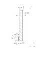
FIG. 1 is a perspective view showing a schematic configuration of a virtual
As shown in FIGS. 1 to 3, the virtual
この虚像表示装置1では、投射装置2から投射された表示光束は、入射側導光装置3に入射される。入射側導光装置3に入射された表示光束は、内面反射を繰り返しつつ、入射側導光装置3の長軸方向(後述するX方向であり、本発明の第2方向)に進行して、外部との界面である出射面31Bに到達する。この出射面31Bに到達した表示光束のうち、一部の光は、当該出射面31Bにて内面反射されて上記長軸方向に更に進行するが、他の光は、外部に出射され、当該出射面31Bと対向する出射側導光装置4に入射される。この出射側導光装置4に入射された光は、上記長軸方向に対する直交方向(後述するY方向であり、本発明の第1方向)に出射側導光装置4内を内面反射しつつ進行し、外部との界面を構成する出射面41Bに到達する。この出射面41Bに到達した光のうち、一部の光は、当該出射面41Bにて内面反射されて上記直交方向に更に進行するが、他の光は、外部に出射されて画像として視認される。このような画像は、出射側導光装置4の奥側に位置する虚像として視認される。 In the virtual
これら入射側導光装置3及び出射側導光装置4は、それぞれ、導光体と、当該導光体の光入射側及び光出射側に配置される回折格子とを有し、詳しくは後述するが、当該各回折格子が、入射される表示光束を構成する光の入射角と、当該光の波長とに応じた回折角にて当該光を分離及び出射する。これにより、複数の半透過層での反射によって内部を通過する光の一部を順に分離及び出射する導光体で観察される輝度変化の発生を抑制し、虚像として視認される画像の劣化を抑制している。 Each of the incident-side
このような虚像表示装置1の構成のうち、投射装置2については、後に詳述する。
なお、以下の説明及び図において、X、Y及びZ方向は、それぞれ互いに直交する方向である。本実施形態では、Z方向を水平方向に沿う一方向とし、X方向を、水平方向に沿い、かつ、Z方向とは反対側から見て左から右に向かう方向とし、Y方向を、鉛直方向とは反対方向(下から上に向かう方向)とする。Of the configuration of the virtual
In the following description and drawings, the X, Y, and Z directions are directions orthogonal to each other. In this embodiment, the Z direction is one direction along the horizontal direction, the X direction is along the horizontal direction, and the direction from the left to the right when viewed from the opposite side to the Z direction, and the Y direction is the vertical direction. And the opposite direction (from bottom to top).
[入射側導光装置の構成]
入射側導光装置3は、投射装置2から入射される画像を出射側導光装置4に導く機能を有する。この入射側導光装置3は、図1〜図3に示すように、入射側導光体31、入射側回折格子32及び出射側回折格子33を有する。
入射側導光体31は、本発明の第2導光体に相当するものであり、ガラス及び樹脂等の透光性部材により、長軸方向がX方向に沿う略四角柱状に形成されている。この入射側導光体31は、X方向側の一部が出射側導光装置4の一部とZ方向において重なるように、当該出射側導光装置4と対向する位置に配置される。
このような入射側導光体31は、それぞれXY平面に沿う第1面311及び第2面312と、それぞれXZ平面に沿う第3面313及び第4面314と、それぞれYZ平面に沿う第5面315及び第6面316と、を有する。これらのうち、投射装置2及び出射側導光装置4に対向する第1面311を除いた各面312〜316には、全反射層が全面に形成されている。[Configuration of incident-side light guide device]
The incident side
The incident-side
Such an incident side
第1面311は、投射装置2からの表示光束が入射される面であり、また、入射側導光体31内を進行した光が出射される面である。
詳述すると、第1面311において出射側導光装置4とZ方向にて重ならない領域のうち、X方向とは反対側の領域に、上記表示光束が入射される入射面31A(本発明の第2入射面に相当)が設定されている。
また、第1面311において出射側導光装置4とZ方向にて重なる領域は、入射側導光体31の内部をX方向側に進行した光が出射される出射面31B(本発明の第2出射面に相当)が設定されている。
更に、第1面311において、入射面31A及び出射面31B以外の領域には、上記全反射層が形成されている。The
More specifically, of the
In addition, the region of the
Further, the total reflection layer is formed on the
入射側回折格子32は、本発明の第2入射側回折格子に相当し、上記入射面31Aを覆うように取り付けられる。この入射側回折格子32は、入射面31Aから入射された光が入射側導光体31内を繰り返し内面反射されてX方向側に進行するように、当該光を回折する。すなわち、入射側回折格子32は、投射装置2からZ方向に投射された表示光束が入射され、当該表示光束を構成する光を、それぞれの波長に応じた回折角で回折させて、入射面31Aに入射させる。
出射側回折格子33は、本発明の第2出射側回折格子に相当し、上記出射面31Bを覆うように取り付けられる。この出射側回折格子33は、入射側導光体31から入射された光が、出射面31Bから出射される光の進行方向側(すなわち、X方向に直交するZ方向とは反対側)に進行するように、入射された光を回折する。すなわち、出射側回折格子33は、出射面31Bから入射される光(上記表示光束を構成する光)を、それぞれの波長に応じた回折角で回折させて、後述する出射側導光装置4の入射側回折格子42に入射させる。The incident
The exit
これら入射側回折格子32及び出射側回折格子33は、入射光の回折に関して、それぞれ同じ特性を有する。具体的に、各回折格子32,33は、それぞれに同じ波長の光が入射された際に、同じ回折角で回折させる特性を有する。このため、例えば、赤色光に分類される波長660nmの光が、各回折格子32,33のそれぞれに入射された場合、それぞれの回折面に入射される光の進行方向に対する、当該回折面から回折されて出射される光の進行方向の角度(回折角)は、それぞれ同じである。他の波長の光(少なくとも可視光領域の光)も同様である。
なお、これら回折格子32,33は、透過型回折格子であるが、ホログラムシートによって構成してもよい。The incident
The
[入射側導光装置に入射された画像を形成する表示光束の光路]
図4は、入射側導光装置3に入射された光の光路を示す模式図である。詳述すると、図4は、表示光束により形成される画像のX方向における一端及び他端を形成する光の光路を示す図である。
ここで、入射側導光装置3における表示光束の光路について説明する。
図4に示すように、投射装置2から投射される表示光束は、所定の画角を有する。この表示光束は、中心軸CAがZ方向に対して傾斜する方向(換言すると、入射側回折格子32の回折面に対して傾斜する方向)に投射され、当該入射側回折格子32を介して入射側導光体31内に入射される。この際、当該表示光束による画像のX方向における一端側を形成する所定波長の光(以下、一端光という)L1は、図4に一点鎖線で示すように、当該入射側回折格子32の特性に応じた回折角で回折された後、入射側導光体31内に入射される。また、他端側を形成する同波長の光(以下、他端光という)L2は、図4に点線で示すように、当該入射側回折格子32にて同じ回折角で回折された後、入射側導光体31内に入射される。すなわち、一端光L1及び他端光L2は、それぞれ、入射側回折格子32に対する入射角が異なることから、それぞれ異なる出射角で入射側回折格子32から回折されて、入射面31Aを介して入射側導光体31内に導入される。[The optical path of the display light beam forming the image incident on the incident side light guide device]
FIG. 4 is a schematic diagram illustrating an optical path of light incident on the incident-side
Here, the optical path of the display light beam in the incident side
As shown in FIG. 4, the display light beam projected from the
入射側導光体31内に導入された上記一端光L1は、全反射層が形成された界面(面311〜316)にて内面反射を繰り返しつつ、X方向側に進行する。そして、出射面31Bのそれぞれの領域に到達した一端光のうち、一部の光(所定割合の光)は、出射面31Bを通過して出射側回折格子33に入射され、当該出射側回折格子33の特性に応じた回折角で回折されて出射される。一方、他の光は、出射面31Bにて内面反射されて、再びX方向側に進行し、上記界面にて内面反射された後、再び出射面31Bに入射される。そして、当該他の光のうち、更に一部の光が、出射面31B及び出射側回折格子33を介して外部に出射され、残りの光が、当該出射面31Bにて内面反射される。このようにして、上記一端光L1は、入射側導光体31にて内面反射されつつX方向側に進行する際に、出射面31Bに入射されるごとに、一部の光が外部に出射される。 The one-end light L1 introduced into the incident-side
また、入射面31Aに対して傾斜して入射側導光体31内に導入された上記他端光L2も、内面反射を繰り返しつつ、X方向側に進行する。そして、出射面31Bに入射された他端光L2のうち、一部の光(所定割合の光)は、出射面31Bを通過して出射側回折格子33に入射され、当該出射側回折格子33の特性に応じた回折角で回折されて出射される。一方、他の光は、出射面31Bにて内面反射されて、再びX方向側に進行し、更に上記界面にて内面反射された後、再び出射面31Bに入射される。このように、他端光L2は、上記一端光L1と同様に、入射側導光体31にて内面反射されつつX方向側に進行する際に、出射面31Bに入射されるごとに、一部の光が外部に出射される。
これら光が観察者に届くことにより、上記所定の画角の画像が観察される。Further, the other end light L2 that is inclined with respect to the
When these lights reach the observer, an image with the predetermined angle of view is observed.
[入射側導光装置に入射された各波長の光の光路]
ここで、回折格子は、入射された光を、当該光の波長によって異なる回折角にて回折させて出射する機能を有する。この回折角は、光の波長が大きいほど大きくなる。
このため、入射側回折格子32に入射された表示光束を構成する各波長の光は、それぞれ異なる角度にて入射側回折格子32から出射され、入射側導光体31内に入射される。[Optical path of light of each wavelength incident on incident side light guide device]
Here, the diffraction grating has a function of diffracting incident light at a different diffraction angle depending on the wavelength of the light. This diffraction angle increases as the wavelength of light increases.
Therefore, light of each wavelength constituting the display light beam incident on the incident
図5は、入射側導光装置3に入射された表示光束PLを構成し、それぞれ波長が異なる第1色光C1、第2色光C2及び第3色光C3の光路を示す模式図である。
例えば、それぞれ同じ色に分類されるものの波長が異なる第1色光C1(点線)、第2色光C2(一点鎖線)及び第3色光C3(二点鎖線)が、入射側回折格子32に対して入射された場合、それぞれ異なる回折角で回折されることから、図5に示すように、入射側導光体31内への各色光C1〜C3の入射角も異なる。FIG. 5 is a schematic diagram illustrating the optical paths of the first color light C1, the second color light C2, and the third color light C3 that constitute the display light beam PL that is incident on the incident-side
For example, the first color light C1 (dotted line), the second color light C2 (one-dot chain line), and the third color light C3 (two-dot chain line) that are classified into the same color but have different wavelengths are incident on the incident-
これら各色光C1〜C3が、入射側導光体31内を内面反射しつつX方向側に進行し、当該各色光C1〜C3のそれぞれの一部が、出射面31Bから出射されて、出射側回折格子33に入射されると、それぞれ波長に応じた回折角にて回折されて出射される。この際、入射側回折格子32と出射側回折格子33とは、波長に応じた回折角が同じ特性を有することから、出射側回折格子33からの第1色光C1、第2色光C2及び第3色光C3の出射角は、それぞれ同じとなる。
このように、入射される光の波長に応じて入射側回折格子32からの出射角、ひいては、入射側導光体31内への入射角が異なることから、それぞれの波長の光の光路は異なり、当該それぞれの波長の光は、出射側回折格子33から同じ出射角で出射されるものの、出射面31Bにおける各光の出射位置は異なることとなる。Each of the color lights C1 to C3 travels in the X direction while being internally reflected in the incident side
As described above, since the exit angle from the incident-
ここで、例えば、中心軸に対して傾斜する複数の半透過層が内部に形成された導光体に表示光束を入射させ、それぞれの半透過層にて反射させることで、当該表示光束の一部の光を導光体外に出射する構成では、出射される光の輝度変化から、当該半透過層の存在が視認されてしまう。また、このような光が、虚像として視認される画像に重畳されて視認されると、当該画像が劣化する。
これに対し、上記各色光C1〜C3のように、入射側導光体31内をX方向側に進行した光は、同じ色に分類される光であっても、当該光の波長によって、出射側回折格子33における異なる位置から出射される。すなわち、表示光束が、複数の色に分類される所定の波長幅の色光を含む光束であれば、当該表示光束に含まれる光は、出射側回折格子33においてそれぞれ異なる位置から出射される。これによれば、当該出射側回折格子33から光を分散して出射できる。従って、入射側導光体31内の構造が視認されるような事態を抑制できる他、視認される画像の劣化を抑制できる。
なお、詳しくは後述するが、出射側導光装置4の構成も、入射側導光装置3と同様である。このため、投射装置2は、比較的波長幅の広い複数の色光により構成される表示光束を、上記入射側導光装置3に投射する。この投射装置2の構成は、後に詳述する。Here, for example, a display light beam is made incident on a light guide body in which a plurality of semi-transmissive layers inclined with respect to the central axis are formed, and reflected by each semi-transmissive layer. In the configuration in which the light of the part is emitted out of the light guide, the presence of the semi-transmissive layer is visually recognized from the luminance change of the emitted light. In addition, when such light is superimposed on an image that is visually recognized as a virtual image, the image is deteriorated.
On the other hand, as in the color lights C1 to C3, the light traveling in the X direction side in the incident side
In addition, although mentioned later in detail, the structure of the output side
[出射側導光装置の構成]
出射側導光装置4は、入射側導光装置3から入射される表示光束を、出射側導光装置4に対してZ方向とは反対側に分散して出射することにより、当該表示光束により形成される画像を虚像として視認させる機能を有する。このような出射側導光装置4は、入射側導光装置3と同様の構成を有し、具体的には、図1〜図3に示すように、出射側導光体41、入射側回折格子42及び出射側回折格子43を備える。[Configuration of Output-side Light Guide Device]
The exit-side
出射側導光体41は、本発明の第1導光体に相当するものであり、ガラス及び樹脂等の透光性部材により、略矩形の板状に形成されている。この出射側導光体41は、Y方向とは反対側の端部が、出射面31Bを覆う出射側回折格子33とZ方向において重なるように、XY平面に沿って配置される。また、出射側導光体41におけるY方向の寸法は、出射側回折格子33におけるY方向の寸法より大きい。
このような出射側導光体41は、それぞれXY平面に沿う第1面411及び第2面412と、それぞれXZ平面に沿う第3面413及び第4面414と、それぞれYZ平面に沿う第5面415及び第6面416と、を有する。これらのうち、第1面411及び第2面412を除いた各面413〜416には、全反射層が全面に形成されている。The emission side
Such an output side
第2面412において、入射側導光装置3とZ方向にて重なる領域は、当該入射側導光装置3から出射された表示光束が入射される入射面41A(本発明の第1入射面に相当)とされている。この入射面41AにおけるX方向の寸法は、入射側導光装置3から出射される表示光束の全てが入射されるように、出射側回折格子33におけるX方向の寸法と略一致する。この第2面412において入射面41A以外の領域には、全反射層が形成されている。
第1面411の略全面は、出射側導光体41内を進行した光が出射される出射面41B(本発明の第1出射面に相当)とされている。
このような出射側導光体41は、詳しくは後述するが、入射面41Aから入射された表示光束を、外部との界面(主に第1面411及び第2面412)にて内面反射させつつ、入射面41Aから離れる方向であるY方向側に進行させる。この際、出射面41Bのそれぞれの領域にて入射された光の一部は、当該出射面41Bから外部に出射され、残りの光は、当該出射面41Bにて内面反射され、更にY方向側に進行する。A region of the
A substantially entire surface of the
As will be described in detail later, such an exit-side
入射側回折格子42は、本発明の第1入射側回折格子に相当し、上記入射面41Aを覆うように、当該入射面41Aに取り付けられる。この入射側回折格子42は、入射面41Aから入射された光が出射側導光体41内を繰り返し内面反射されてY方向側に進行するように、当該光を回折する。すなわち、入射側回折格子42は、上記出射側回折格子33から入射される表示光束に含まれる光を、それぞれの光の波長に応じた回折角にて回折させ、入射面41Aに入射させる。
出射側回折格子43は、本発明の第1出射側回折格子に相当し、上記出射面41Bを覆うように、当該出射面41Bに取り付けられる。この出射側回折格子43は、出射側導光体41から入射された光が、出射面41Bから出射される光の進行方向側(Y方向に直交するZ方向とは反対側)に進行するように、入射された光を回折する。すなわち、出射側回折格子43は、出射面41Bから出射された光を、それぞれの光の波長に応じた回折角にて回折させて外部に出射する。The incident
The exit
ここで、入射側回折格子42及び出射側回折格子43は、上記回折格子32,33の関係と同様に、入射光の回折に関して、それぞれ同じ特性を有する。このため、入射側回折格子42を介して出射側導光体41内に入射された光は、当該出射側導光体41の出射面41Bから出射側回折格子43に入射され、当該光が入射側回折格子42に入射された際の入射角と同じ角度となる出射角にて出射側回折格子43から出射される。
なお、これら回折格子42,43は、上記回折格子32,33と同様に透過型回折格子であるが、ホログラムシートによって構成してもよい。Here, the incident-
The
[出射側導光装置に入射された光の光路]
図6及び図7は、出射側導光装置4に入射された光の光路を示す模式図である。なお、図6及び図7においては、出射側導光装置4に入射される上記表示光束を構成する光のうち、投射装置2から投射された表示光束の中心軸に沿って上記入射側導光装置3に入射され、当該入射側導光装置3から出射側導光装置4に入射される所定波長の光の光路が示されている。
入射側回折格子42には、上記出射側回折格子33の略全面から、上記表示光束を構成する光が入射される。具体的に、当該表示光束の所定部位を形成する所定波長の光のみに言及した場合でも、図6に示すように、当該所定波長の光は、出射側回折格子33のX方向における複数箇所から入射側回折格子42に入射される。そして、入射側回折格子42は、入射された光を、当該入射側回折格子42が有する特性、及び、当該光の波長に応じた回折角で回折させて、入射面41Aから出射側導光体41内に入射させる。この際、当該入射側回折格子42は、入射された光の進行方向をY方向側に導くように設定されている。このため、出射側導光体41内に導入された光は、図7に示すように、Z方向とは反対側に進行するとともに、Y方向側に進行し、出射面41Bのそれぞれの領域に到達する。[The optical path of the light incident on the exit-side light guide device]
6 and 7 are schematic views showing the optical path of the light incident on the exit-side
The light constituting the display light beam is incident on the incident
出射面41Bに到達した光のうち、一部の光(所定割合の光)は、上記と同様に、当該出射面41Bから外部に出射され、当該出射面41Bに配置された出射側回折格子43に入射される。また、他の光は、当該出射面41Bにて内面反射されて、Z方向側及びY方向側に更に進行する。この光は、他の界面にて内面反射されて再び出射面41Bに入射され、当該光の一部が、更に外部に出射される。このように、出射側導光体41内に導入された光は、内面反射を繰り返しつつ、Y方向側に進行する。 Of the light reaching the
出射側回折格子43に入射された光は、当該出射側回折格子43に対する光の入射角と、当該光の波長とに応じた回折角で回折されて、出射側導光装置4に対してZ方向とは反対側に出射される。
ここで、出射側回折格子43と、入射側回折格子42とは、それぞれ同じ特性を有するので、出射側回折格子43は、入射された光を、当該光が入射側回折格子42に入射された際の入射角と同じ角度の出射角で出射する。このため、図6及び図7に示すように、入射側回折格子42の回折面に対して傾斜して光が入射される場合には、同じ角度だけ傾斜する方向に、当該光が出射側回折格子43から出射される。これにより、観察者は、出射側回折格子43に対してZ方向とは反対側で、かつ、当該光の入射範囲内に位置していれば、どの位置に居ても、出射される光により形成される画像、すなわち、投射装置2が入射側回折格子32に投射した画像が、出射側導光装置4に対してZ方向側に位置する虚像として視認される。The light incident on the output
Here, since the exit
[投射装置の構成]
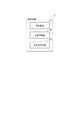
図8は、投射装置2の構成を示すブロック図である。
投射装置2は、画像情報に応じた画像を形成及び投射する。この投射装置2は、図8に示すように、光源装置21、光変調装置22及び投射光学装置23を有する。
これらのうち、光変調装置22は、光源装置21から出射された光を変調して、画像情報に応じた画像を形成する。このような光変調装置22としては、少なくとも1つの透過型又は反射型の液晶パネルを採用できる他、マイクロミラーを用いたデバイス(例えばDMD(Digital Micromirror Device))を採用できる。
投射光学装置23は、光変調装置22により形成された画像を、表示光束として投射する。この際、投射光学装置23は、当該表示光束を上記入射側回折格子32の略中央に集約させて出射する。[Configuration of Projection Device]
FIG. 8 is a block diagram illustrating a configuration of the
The
Among these, the
The projection
光源装置21は、上記光変調装置22に光を出射する。ここで、上記回折格子32,33,42,43は、入射された表示光束に含まれる各波長の光を、当該光の波長に応じた回折角で分離及び出射する。このことから、光源装置21は、所定の波長幅を有する色光を出射して、光変調装置に、当該色光が含まれる画像を形成させる。
具体的に、光源装置21は、赤、緑及び青に分類される各色光を含む光を出射するが、それぞれの色光は、所定の波長幅(例えば10nm以上の波長幅)を有する光により構成される。この波長幅は、連続していても、連続していなくてもよい。このような光を光源装置21が出射することにより、上記輝度変化の発生が抑制されることとなる。
なお、このような光を出射する光源装置21としては、超高圧水銀ランプ等の放電光源ランプを有する構成を例示できる他、LED(Light Emitting Diode)を有する構成を例示できる。The
Specifically, the
In addition, as the
[第1実施形態の効果]
以上説明した本実施形態に係る虚像表示装置1によれば、以下の効果がある。
入射面41Aの光入射側に位置する入射側回折格子42は、入射される表示光束を構成する光が出射側導光体41内を繰り返し内面反射されてX方向側に進行するように、当該光を、それぞれの波長毎に異なる回折角で回折する。これにより、それぞれ波長が異なる光は、それぞれ異なる領域にて内面反射を繰り返しつつ、入射面41Aから離れる方向であるY方向側に進行し、出射面41Bにおいてそれぞれ異なる領域に入射される。出射面41Bの当該各位置から出射されたそれぞれの光は、出射側回折格子43を通過する際に、それぞれの波長に応じた回折角で再度回折されて出射される。これにより、当該出射側回折格子43に対してZ方向に対向し、かつ、Y方向における任意の位置で、入射された光により形成される画像を、出射側導光体41に対するZ方向側に位置する虚像として視認できる。[Effect of the first embodiment]
The virtual
The incident-
入射側回折格子42による回折により、出射側導光体41内に入射される光の入射角は、波長によって異なる。これにより、それぞれの波長の光は、出射側導光体41内を異なる光路にて進行するので、当該光を出射面41Bにおけるそれぞれ異なる位置から分散して出射させることができる。
また、入射側回折格子42を介して入射される光の入射角は、図4に示したように、表示光束における位置によって異なる。このことから、当該表示光束を構成する光の位置に応じて、出射側導光体41内での光路を異ならせることができる。これにより、出射面41Bにおけるそれぞれの光の入射位置を異ならせることができ、ひいては、当該光を出射面41B及び出射側回折格子43を介して、分散して出射させることができる。また、出射面41Bから出射された光は、出射側回折格子43を介して外部に出射されることにより、出射面41Bからの光の出射角を波長毎に調整できる。
このような虚像表示装置1によれば、Y方向に対して傾斜する複数の半透過層が内部に形成された導光体に表示光束を入射させ、それぞれの半透過層によって反射された光を出射する構成を採用した場合に生じる輝度変化の発生を抑制できる。従って、当該輝度変化が視認されて、出射される光によって形成される画像が劣化することを抑制できる。Due to diffraction by the incident
Further, the incident angle of the light incident through the incident
According to such a virtual
入射側回折格子42と出射側回折格子43とは、入射光の回折に関して、それぞれ同じ特性を有する。このため、入射側回折格子42による回折角と、出射側回折格子43による回折角とは、入射される光の波長毎にそれぞれ同じとなる。これによれば、入射側回折格子42への光の入射角と、出射側回折格子43からの当該光の出射角とを、同じ角度にすることができる。従って、虚像表示装置1からの光の出射角を容易に調整できる他、当該光によって形成される画像を観察者が視認しやすくすることができる。 The incident
入射側導光体31は、内部に入射された光を繰り返し内面反射させてX方向側に進行させるとともに、外部との界面である出射面31Bにて内面反射させる際に、一部の光を外部に出射して、上記出射側導光装置4に入射させる。これによれば、入射側導光体31がX方向に長く形成され、出射側導光体41が、X方向及びY方向に長く形成されていることにより、表示光束を構成する光を、入射側導光装置3によりX方向に分散させ、当該出射側導光装置4によりY方向に分散させて出射できる。従って、表示光束により形成される画像を視認可能な範囲を、X方向及びY方向のそれぞれに拡大できる。 The incident-side
入射側導光装置3は、上記入射側導光体31に加えて、入射側回折格子32と、出射側回折格子33と、を備える。これによれば、入射側回折格子32を介して表示光束を入射側導光体31内に入射させることにより、当該表示光束に含まれる光の波長及び当該光の入射角に応じて、それぞれの光が入射側導光体31内を進行する際の光路を異ならせることができる。これにより、当該光を出射側回折格子33においてそれぞれ異なる位置に入射させることができる。この出射側回折格子33は、それぞれ入射された光を波長毎に異なる回折角で回折させて、入射側導光装置3の外部に出射させるので、当該光を入射側導光装置3の外部に、確実に分散して出射させることができる他、当該外部への光の出射角を波長毎に調整できる。従って、出射側導光装置4に入射させる表示光束を、X方向に確実に分散して出射させることができる。 The incident side
出射面31Bと入射面41Aとは、互いに対向する位置に配置されるので、入射側導光装置3の出射側回折格子33から出射された光を、出射側導光装置4の入射側回折格子42に入射させやすくすることができる。
また、入射側回折格子32に入射された光が出射される際の回折角と、出射側回折格子33に入射された光が出射される際の回折角とは、当該光の波長毎にそれぞれ同じとなる。これによれば、入射側回折格子42及び出射側回折格子43の関係と同様に、入射側回折格子32に対する光の入射角と、出射側回折格子33からの光の出射角とを、同じ角度にすることができる。従って、入射側導光装置3から出射側導光装置4に入射される光の進行方向を把握しやすくすることができ、入射側導光装置3から出射側導光装置4に、光を確実に入射させることができる。Since the
The diffraction angle when the light incident on the incident
ここで、波長幅が比較的狭い色光を含む表示光束が、入射側回折格子32、ひいては、入射側回折格子42に入射される場合には、当該色光は、それぞれ略同じ回折角で回折されて入射側導光体31及び出射側導光体41に入射される。このため、同じ色に分類されるもののそれぞれ波長が異なる光は、導光体31,41内を略同じ光路で進行するため、出射面31B,41Bにおける略同じ位置に入射される。このような場合、同じ色に分類される光が、出射面31B,41Bにおける略同じ位置から出射されてしまうため、当該光が分散されず、上記複数の半透過層を有する導光体を採用した場合の輝度変化が生じる可能性がある。
これに対し、それぞれの色光が上記所定の波長幅(10nm以上の波長幅)を有することにより、入射側回折格子32,42を介して入射面31A,41Aに入射される際の入射角を異ならせることができる。これにより、導光体31,41内において、同じ色に分類されるものの波長が異なる色光の光路を異ならせることができ、それぞれの色光の出射面31B,41Bへの入射位置を異ならせることができる。従って、出射面31B,41Bにおいて、それぞれの色光の出射位置を分散させることができるので、当該輝度変化の発生を抑制でき、ひいては、視認される画像の劣化を抑制できる。Here, when a display light beam including colored light having a relatively narrow wavelength width is incident on the incident-
On the other hand, since each color light has the predetermined wavelength width (wavelength width of 10 nm or more), the incident angles when entering the incident surfaces 31A and 41A via the incident-
[第1実施形態の変形]
上記虚像表示装置1では、内面反射を繰り返して進行する光は、出射面31B,41Bに到達する毎に、所定割合の光が外部に出射され、残りの光が内面反射されることから、出射面31B,41Bから出射される光の光量(輝度)は、導光体31,41内を進行する光の進行方向に向かうに従って少なくなる(低くなる)。具体的に、出射側回折格子33からの出射光量は、入射面31Aから遠ざかるX方向に向かうに従って少なくなり、また、出射側回折格子43からの出射光量は、入射面41Aから遠ざかるY方向に向かうに従って少なくなる。このため、X方向とは反対側で、かつ、Y方向とは反対側にて視認される画像に比べて、X方向側で、かつ、Y方向側にて視認される画像の輝度は低くなる。
このように、観察位置によって、観察される画像の輝度が異なるという現象が生じる。[Modification of First Embodiment]
In the virtual
In this way, a phenomenon occurs in which the brightness of the observed image differs depending on the observation position.
これに対し、出射側回折格子33,43の回折効率を、部位によって異ならせてもよい。
例えば、出射側回折格子33を、入射側導光体31内における光の進行方向であるX方向に向かうに従って、回折効率が上昇する特性を有する構成としてもよい。このように構成された出射側回折格子33では、当該X方向に向かうに従って、入射光の光量に対する出射光の光量の割合が高くなる。換言すると、当該出射側回折格子33は、X方向に向かうに従って、入射される光の透過率が上昇し、また、当該光の反射効率が低減される特性を有する。これにより、入射側導光装置3(出射側回折格子33)から出射される光の光量を、X方向で略均一にすることができる。
同様に、出射側回折格子43を、出射側導光体41内における光の進行方向であるY方向に向かうに従って、回折効率が上昇する特性を有する構成としてもよい。このように構成された出射側回折格子43では、当該Y方向に向かうに従って、入射光の光量に対する出射光の光量の割合が高くなる。換言すると、当該出射側回折格子43は、Y方向に向かうに従って、入射される光の透過率が上昇し、また、当該光の反射効率が低減される特性を有する。これにより、出射側導光装置4(出射側回折格子43)から出射される光の光量を、Y方向で略均一にすることができる。On the other hand, the diffraction efficiencies of the exit
For example, the exit-
Similarly, the exit-
図9及び図10は、上記虚像表示装置1の変形である虚像表示装置1Aの構成と、当該虚像表示装置1Aを構成する入射側導光装置3A及び出射側導光装置4Aを通過する光の光路を示す模式図である。これらのうち、図9は、XZ平面での虚像表示装置1Aの構成を示し、図10は、YZ平面での虚像表示装置1Aの構成を示している。なお、これら図9及び図10においては、投射装置2の図示を省略している。
また、例えば、図9及び図10に示す虚像表示装置1Aのように、出射面31Bと出射側回折格子33との間、及び、出射面41Bと出射側回折格子43との間に、透過光量調整層34,44を配置してもよい。
この虚像表示装置1Aは、虚像表示装置1と同様に、投射装置2、入射側導光装置3A及び出射側導光装置4Aを備える。これらのうち、入射側導光装置3Aは、出射面31Bと出射側回折格子33との間に透過光量調整層34が配置されている他は、上記入射側導光装置3と同様の構成及び機能を有する。また、出射側導光装置4Aは、出射面41Bと出射側回折格子43との間に透過光量調整層44が配置されている他は、上記出射側導光装置4と同様の構成を有する。9 and 10 show a configuration of the virtual
Further, for example, as in the virtual
Similar to the virtual
透過光量調整層34は、入射側導光体31内における光の進行方向であるX方向に向かうに従って、入射される光の透過率が上昇する特性、及び、当該光の反射効率が低減される特性のいずれかを有する。この透過光量調整層34により、図9に示すように、出射面31BにおけるX方向のそれぞれの出射位置から、透過光量調整層34及び出射側回折格子33を介して外部に出射される光の光量を、それぞれ略同じにできる。
また、透過光量調整層44は、出射側導光体41内における光の進行方向であるY方向に向かうに従って、入射される光の透過率が上昇する特性、及び、当該光の反射効率が低減される特性のいずれかを有する。この透過光量調整層44により、図10に示すように、出射面41BにおけるY方向のそれぞれの出射位置から、透過光量調整層44及び出射側回折格子43を介して外部に出射される光の光量を、それぞれ略同じにできる。The transmitted light
Further, the transmitted light
従って、出射側回折格子33,43が、導光体31,41内における光の進行方向に向かうに従って、回折効率が上昇する特性を有することにより、或いは、上記透過光量調整層34,44が各導光装置3A,4Aに設けられることにより、出射側回折格子43に対向する任意の位置にてそれぞれ観察される画像の輝度を均一化できる。
なお、上記透過光量調整層34は、出射側回折格子33の光出射側に配置されていてもよく、光入射側及び光出射側のそれぞれに配置されていてもよい。
同様に、上記透過光量調整層44は、出射側回折格子43の光出射側に配置されていてもよく、光入射側及び光出射側のそれぞれに配置されていてもよい。Therefore, the exit
The transmitted light
Similarly, the transmitted light
[第2実施形態]
次に、本発明の第2実施形態について説明する。
本実施形態に係る虚像表示装置は、上記虚像表示装置1と同様の構成に加えて、出射側導光装置4を構成する出射側回折格子43の光出射側に、当該出射側回折格子43から出射された光の進行方向を調整する方向調整層が配置されている。この点で、本実施形態に係る虚像表示装置は、上記虚像表示装置1と相違する。なお、以下の説明では、既に説明した部分と同一又は略同一である部分については、同一の符号を付して説明を省略する。[Second Embodiment]
Next, a second embodiment of the present invention will be described.
In addition to the same configuration as the virtual
図11は、本実施形態に係る虚像表示装置1Bの構成、及び、当該虚像表示装置1Bから出射される光の光路を示す模式図である。なお、図11では、投射装置2の図示を省略している。
本実施形態に係る虚像表示装置1Bは、図11に示すように、上記出射側導光装置4に代えて出射側導光装置4Bを有する他は、上記虚像表示装置1と同様の構成及び機能を有する。また、出射側導光装置4Bは、上記出射側導光装置4の構成に加えて、方向調整層45を更に有する。FIG. 11 is a schematic diagram illustrating a configuration of the virtual
As shown in FIG. 11, the virtual
方向調整層45は、出射側回折格子43の光出射側に位置し、当該出射側回折格子43を覆うように配置されている。この方向調整層45は、出射側回折格子43から入射される光の進行方向を調整する機能を有する。具体的に、方向調整層45は、投射装置2から投射された表示光束の中心となる光(上記中心光であり、画像の中心を形成する光)が、当該方向調整層45の法線方向(出射側回折格子43の法線方向)に沿って出射されるように、当該方向調整層45を通過する全ての光の進行方向を調整する。このような方向調整層45は、複数の微小なプリズムが形成されたプリズムシートにより構成できる。 The
[第2実施形態の効果]
以上説明した本実施形態に係る虚像表示装置1Bによれば、上記虚像表示装置1と同様の効果を奏することができる他、以下の効果を奏することができる。
方向調整層45が出射側回折格子43の光出射側に配置されていることにより、当該出射側回折格子43から出射される上記中心光の進行方向が、当該出射側回折格子43の法線(すなわち、出射面41Bの法線)に沿わない場合でも、当該中心光が出射側回折格子43の法線及び出射面41Bの法線に沿って出射されるように、当該方向調整層45を通過する光の進行方向を調整できる。従って、出射側回折格子43及び出射面41Bに対して視方向を傾斜させることなく、出射側導光装置4から出射された光により形成される画像を視認できるので、当該画像を視認しやすくすることができる。[Effects of Second Embodiment]
According to the virtual
Since the
なお、このような虚像表示装置1Bが有する出射側回折格子33,43を、上記第1実施形態の変形で示した特性を有する構成としてもよい。また、当該虚像表示装置1Bが、上記透過光量調整層34,44を有する構成としてもよい。これらの場合、いずれの観察位置においても、それぞれ略同じ輝度の画像を視認できるという効果を享受でできる。 In addition, it is good also as a structure which has the characteristic shown by the deformation | transformation of the said 1st Embodiment of the output
[第3実施形態]
次に、本発明の第3実施形態について説明する。
本実施形態に係る虚像表示装置は、上記虚像表示装置1と同様の構成を有する。ここで、当該虚像表示装置1においては、投射装置2は、入射側導光装置3に対してZ方向とは反対側に位置し、Z方向に上記表示光束を投射する構成であった。これに対し、本実施形態に係る虚像表示装置では、投射装置は、入射側導光装置3に対してY方向側に位置し、Y方向とは反対方向に上記表示光束を投射する。この点で、本実施形態に係る虚像表示装置と、上記虚像表示装置1とは相違する。なお、以下の説明では、既に説明した部分と同一又は略同一である部分については、同一の符号を付して説明を省略する。[Third Embodiment]
Next, a third embodiment of the present invention will be described.
The virtual image display device according to the present embodiment has the same configuration as the virtual
図12は、本実施形態に係る虚像表示装置1Cの概略構成を示す斜視図である。
本実施形態に係る虚像表示装置1Cは、図12に示すように、投射装置2、入射側導光装置3C及び出射側導光装置4Cと、これらを内部に収納する筐体5とを備え、上記虚像表示装置1と同様の機能を有する。
なお、本実施形態では、X、Y及びZ方向は、上記第1及び第2実施形態にて示したX、Y及びZ方向とそれぞれ同じ方向とする。FIG. 12 is a perspective view showing a schematic configuration of a virtual image display device 1C according to the present embodiment.
As shown in FIG. 12, the virtual image display device 1C according to the present embodiment includes the
In this embodiment, the X, Y, and Z directions are the same as the X, Y, and Z directions shown in the first and second embodiments, respectively.
投射装置2は、本実施形態では、表示光束の投射方向がY方向とは反対方向となるように、入射側導光装置3のY方向側に位置する。
入射側導光装置3Cは、上記入射側導光装置3と同様に、長軸方向がX方向に沿う入射側導光体31と、入射側回折格子32及び出射側回折格子33と、を備える。しかしながら、本実施形態では、入射側回折格子32は、入射側導光体31においてY方向側を向く第3面313におけるX方向とは反対側の領域である入射面31Aを覆うように取り付けられ、出射側回折格子33は、当該第3面313におけるX方向側の領域である出射面31Bを覆うように取り付けられている。そして、各面311,312,314〜316の全面と、第3面313における入射面31A及び出射面31B以外の領域とには、全反射層が形成されている。すなわち、入射側導光装置3Cは、入射側導光体31の第1面311がY方向側を向くように配置した入射側導光装置3と同じ構成である。
このような入射側導光装置3Cに対して投射装置2から投射された表示光束は、それぞれY方向側を向く入射側回折格子32及び入射面31Aを介して、入射側導光体31内に入射され、内面反射を繰り返しつつX方向側に進行し、同じくY方向側を向く出射面31B及び出射側回折格子33を介して、出射側導光装置4Cに向けて出射される。In the present embodiment, the
Similar to the incident-side
The display light beam projected from the
出射側導光装置4Cは、上記出射側導光装置4と同様に、XY平面に沿って配置される略矩形板状の出射側導光体41、入射側回折格子42及び出射側回折格子43を有する。しかしながら、本実施形態においては、入射側回折格子42は、出射側導光体41においてY方向とは反対側の第4面414に取り付けられており、当該第4面414が、出射側導光体41における入射面41Aとされている。また、出射側回折格子43は、出射側導光体41においてZ方向とは反対側の第1面411に取り付けられており、当該第1面411が、出射側導光体41における出射面41Bとされている。
なお、他の面412,413,415,416の全面には、それぞれ全反射層が形成されている。The output-side
A total reflection layer is formed on the entire surface of the
このような出射側導光装置4Cにおいて、出射側回折格子33から入射側回折格子42を介して出射側導光体41内に入射された光は、全反射層が形成された411〜413,415,416(主には第2面412と出射面41Bとの間)にて内面反射を繰り返しつつY方向側に進行する。この際、出射面41Bに到達した光の一部(所定割合の光)が、上記と同様に、出射面41Bから出射され、他の光が、当該出射面41Bにて内面反射されて、更にY方向側に進行し、再び出射面41Bに入射される。このようにして出射面41Bから出射された光は、出射側回折格子43を介して、虚像表示装置1C外に出射される。
このようにして、上記虚像表示装置1Cから出射された光による画像は、上記虚像表示装置1から出射された光による画像と同様に、X方向及びY方向におけるそれぞれの観察位置にて、虚像として視認される。In such an exit-side
In this way, the image by the light emitted from the virtual image display device 1C is a virtual image at each observation position in the X direction and the Y direction, similarly to the image by the light emitted from the virtual
[第3実施形態の効果]
以上説明した本実施形態に係る虚像表示装置1Cによれば、上記虚像表示装置1と同様の効果を奏することができる。
なお、このような虚像表示装置1Cが有する出射側回折格子33,43を、上記第1実施形態の変形で示した特性を有する構成としてもよい。また、当該虚像表示装置1Bが、上記透過光量調整層34,44を有する構成としてもよい。これらの場合、いずれの観察位置においても、それぞれ略同じ輝度の画像を視認できるという効果を奏することができる。更に、上記方向調整層45を、出射側回折格子43の光出射側に配置してもよい。[Effect of the third embodiment]
According to the virtual image display device 1C according to the present embodiment described above, the same effects as those of the virtual
In addition, it is good also as a structure which has the characteristic shown by the deformation | transformation of the said 1st Embodiment of the output
[第4実施形態]
次に、本発明の第4実施形態について説明する。
本実施形態に係る虚像表示装置は、上記虚像表示装置1Bと同様の構成を有する。ここで、当該虚像表示装置1Bでは、入射側回折格子32,42及び出射側回折格子33,43は、それぞれ透過型回折格子により構成され、それぞれ入射面31A,41A及び出射面31B,41Bに対向する位置に配置されていた。これに対し、本実施形態に係る虚像表示装置では、入射側回折格子及び出射側回折格子は、それぞれ反射型回折格子により構成され、入射側導光体31及び出射側導光体41に対する位置が異なる。この点で、本実施形態に係る虚像表示装置と上記虚像表示装置1とは相違する。なお、以下の説明では、既に説明した部分と同一又は略同一である部分については、同一の符号を付して説明を省略する。[Fourth Embodiment]
Next, a fourth embodiment of the present invention will be described.
The virtual image display device according to the present embodiment has the same configuration as the virtual
図13は、本実施形態に係る虚像表示装置1Dの構成、及び、当該虚像表示装置1Dから出射される光の光路を示す模式図である。
本実施形態に係る虚像表示装置1Dは、図13に示すように、投射装置2(図示省略)と、当該投射装置2から表示光束が入射される入射側導光装置3Dと、当該表示光束が入射側導光装置3Dを介して入射される出射側導光装置4Dとを備え、当該虚像表示装置1Bと同様の機能を有する。FIG. 13 is a schematic diagram illustrating a configuration of the virtual
As shown in FIG. 13, the virtual
図14は、入射側導光装置3Dの構成、及び、入射側導光装置3Dを通過する光の光路を示す模式図である。
入射側導光装置3Dは、図14に示すように、第2導光体に相当する入射側導光体31と、第2入射側回折格子に相当する入射側回折格子32Dと、第2出射側回折格子に相当する出射側回折格子33Dと、透過光量調整層34と、を有し、上記入射側導光装置3Aと同様の機能を有する。
入射側導光体31は、上記のように、長軸方向がX方向に沿う略四角柱状に形成されている。この入射側導光体31における第1面311のX方向とは反対側の領域には、投射装置2から表示光束が入射される入射面31Aが設定され、X方向側の領域には、出射側導光装置4Dに向けて表示光束を出射する出射面31Bが設定されている。また、入射側導光体31の各面312〜316のうち、面313〜316には、全反射層が形成されているが、第1面311及び当該第1面311とは反対側に位置する第2面312には、一部(入射側回折格子32Dと出射側回折格子33D及び透過光量調整層34との間)を除いて、全反射層が形成されていない。FIG. 14 is a schematic diagram illustrating a configuration of the incident-side
As shown in FIG. 14, the incident-side
As described above, the incident-side
入射側回折格子32Dは、反射型回折格子により構成され、第2面312と対向する位置に配置されている。詳述すると、入射側回折格子32Dは、入射側導光体31を挟んで入射面31Aと対向する位置に配置されている。この入射側回折格子32Dには、入射面31Aを介して入射側導光体31内に入射された表示光束が入射される。そして、入射側回折格子32Dは、入射された表示光束を構成する光を、当該光の波長に応じた回折角、及び、当該入射側回折格子32Dの入射面に対する入射角に応じた角度にて回折して、入射側導光体31の他の面(例えば第1面311)に臨界角以上の角度にて入射されるように、当該光を反射させる。このような入射側回折格子32Dにより反射された光は、入射側導光体31内を繰り返し内面反射しつつ、X方向側に進行する。 The incident
出射側回折格子33Dは、入射光の回折に関して上記入射側回折格子32Dと同じ特性を有する反射型回折格子により構成され、第2面312と対向する位置に配置されている。詳述すると、出射側回折格子33Dは、入射側導光体31を挟んで上記出射面31Bと対向する位置に配置されている。この出射側回折格子33Dには、入射側導光体31内をX方向側に進行して第2面312に入射された光の一部が入射される。そして、出射側回折格子33Dは、波長及び当該出射側回折格子33Dの入射面に対する入射角に応じて、入射された光を回折して反射させる。この出射側回折格子33Dによって回折された光は、上記出射面31Bの臨界角より小さな角度にて当該出射面31Bに入射され、当該出射面31Bから入射側導光装置3Dの外部に出射される。 The exit
透過光量調整層34は、第2面312と出射側回折格子33Dとの間に配置される。この透過光量調整層34は、入射される光のうち、一部の光を透過させて出射側回折格子33Dに入射させるとともに、他の一部の光を、当該透過光量調整層34に対する入射角と同じ角度にて反射させる。この透過光量調整層34は、X方向に向かうに従って、入射される光の反射効率が低減される特性を有する。 The transmitted light
このような入射側導光装置3D内に入射面31Aを介して投射装置2から入射された表示光束は、入射側回折格子32Dによって回折されて反射され、内面反射を繰り返しつつ入射側導光体31内をX方向に進行する。そして、第2面312に到達した表示光束のうち、一部の光は、透過光量調整層34にて反射されて更にX方向に進行し、内面反射を繰り返して、再び第2面312に到達する。一方、第2面312に到達した表示光束のうち、他の光は、透過光量調整層34を介して出射側回折格子33Dに入射され、当該出射側回折格子33Dによって回折されて反射される。この出射側回折格子33Dによって反射された光は、第2面312とは反対側に位置する出射面31BからZ方向とは反対方向に出射され、出射側導光装置4Dに入射される。この際、透過光量調整層34は、X方向に向かうに従って反射効率が低減される特性を有することから、X方向において出射側回折格子33Dに入射される光の光量は略同じとなり、これにより、X方向において入射側導光装置3Dから出射される光の光量を均一化できる。 The display light beam incident from the
出射側導光装置4Dは、図13に示すように、第1導光体に相当する出射側導光体41と、第1入射側回折格子に相当する入射側回折格子42Dと、第1出射側回折格子に相当する出射側回折格子43Dと、透過光量調整層44と、方向調整層45と、を有し、上記出射側導光装置4Bと同様の機能を有する。
出射側導光体41は、上記のように、XY平面に沿う略矩形板状に形成されている。この出射側導光体41においてZ方向側の面である第2面412のY方向とは反対側の領域には、入射側導光装置3Dから表示光束が入射される入射面41Aが設定されている。また、当該第2面412に対向する第1面411のY方向側の領域には、出射側導光体41内を進行した表示光束を外部に出射して、当該表示光束により形成される画像を視認可能とする出射面41Bが設定されている。更に、出射側導光体41の各面413〜416には、全反射層が形成されているが、第1面411及び第2面412には、全反射層が形成されていない。As shown in FIG. 13, the exit-side
As described above, the emission-side
入射側回折格子42Dは、反射型回折格子により構成され、第1面411のY方向とは反対側の領域と対向する位置に配置されている。詳述すると、入射側回折格子42Dは、出射側導光体41を挟んで入射面41Aと対向する位置に配置されている。この入射側回折格子42Dは、入射面41Aを介して出射側導光体41内に入射された表示光束が入射される。そして、入射側回折格子42Dは、上記入射側回折格子32Dと同様に、入射された表示光束を構成する光を、当該光の波長に応じた回折角、及び、当該入射側回折格子42Dの入射面に対する入射角に応じた角度にて回折して、出射側導光体41の他の面(例えば第2面412)に臨界角以上の角度にて入射されるように、当該光を反射させる。このような入射側回折格子42Dにより反射された光は、出射側導光体41内を繰り返し内面反射しつつ、Y方向側に進行する。 The incident
出射側回折格子43Dは、入射光の回折に関して上記入射側回折格子42Dと同じ特性を有する反射型回折格子により構成され、第2面412のY方向側の領域と対向する位置に配置されている。詳述すると、出射側回折格子43Dは、出射側導光体41を挟んで出射面41Bに対向する位置に配置されている。この出射側回折格子43Dには、出射側導光体41内をY方向側に進行して第2面412に入射された光の一部が入射される。そして、出射側回折格子43Dは、波長及び当該出射側回折格子43Dの入射面に対する入射角に応じて、入射された光を回折して反射させる。この出射側回折格子43Dによって回折された光は、上記出射面41Bの臨界角より小さな角度にて当該出射面41Bに入射され、当該出射面41Bから出射側導光装置4D、ひいては、虚像表示装置1Dの外部に出射される。 The exit
透過光量調整層44は、第2面412と出射側回折格子43Dとの間に配置される。この透過光量調整層44は、上記透過光量調整層34と同様に、入射される光のうち、一部の光を透過させて出射側回折格子43Dに入射させるとともに、他の一部の光を、当該透過光量調整層44に対する入射角と同じ角度にて反射させる。この透過光量調整層44は、Y方向に向かうに従って、入射される光の反射効率が低減される特性を有する。
方向調整層45は、出射面41Bに応じた位置で、当該出射面41Bの光出射側に配置されている。この方向調整層45は、上記中心光(表示光束により形成される画像の中心を形成する光)が、当該方向調整層45の法線方向(出射面41Bの法線方向)に沿って出射されるように、当該方向調整層45を通過する全ての光の進行方向を調整する。The transmitted light
The
このような出射側導光装置4Dに入射面41Aを介して入射側導光装置3Dから入射された表示光束は、入射側回折格子42Dによって回折されて反射され、内面反射を繰り返しつつ出射側導光体41内をY方向に進行する。そして、第2面412に到達した表示光束のうち、一部の光は、透過光量調整層44にて反射されて更にY方向に進行し、内面反射を繰り返して、再び第2面412に到達する。一方、第2面412に到達した表示光束のうち、他の光は、透過光量調整層44を介して出射側回折格子43Dに入射され、当該出射側回折格子43Dによって回折されて反射される。この出射側回折格子43Dによって反射された光は、当該第2面412とは反対側に位置する出射面41BからZ方向とは反対方向に出射され、これにより、当該光は、虚像表示装置1D外に出射される。この際、透過光量調整層44は、Y方向に向かうに従って反射効率が低減される特性を有することから、Y方向において出射側回折格子43Dに入射される光の光量は略同じとなる。これにより、出射側導光装置4Dから出射される光の光量、すなわち、虚像表示装置1Dから出射される光の光量を、X方向及びY方向において均一化できる。 The display light beam incident on the exit-side
[第4実施形態の効果]
以上説明した本実施形態に係る虚像表示装置1Dによれば、上記虚像表示装置1Bと同様の効果を奏することができる。
なお、上記虚像表示装置1Dでは、方向調整層45は省略してもよい。一方、各回折格子32D,33D,42D,43Dに、上記回折効率の上昇特性を設定してもよい。更に、出射面31B,41Bに、内面反射を繰り返しつつ導光体31,41内を進行する光と、出射側回折格子33D,43Dによって回折された光とが、区別されて出射されるように、所定の光学特性を有する層を位置させてもよい。[Effect of Fourth Embodiment]
According to the virtual
In the virtual
[実施形態の変形]
本発明は、上記実施形態に限定されるものではなく、本発明の目的を達成できる範囲での変形、改良等は本発明に含まれるものである。
上記各実施形態では、虚像表示装置1,1A〜1Dは、投射装置2から出射された光をX方向に分散させて出射する入射側導光装置3,3A,3C,3Dと、当該入射側導光装置3,3C,3Dから入射される光をY方向に分散させて出射する出射側導光装置4,4A〜4Dと、を備える構成とした。しかしながら、本発明はこれに限らない。すなわち、虚像表示装置は、投射装置2と、入射側導光装置3,3A,3C,3D及び出射側導光装置4,4A〜4Dのいずれかとにより構成されていてもよい。[Modification of Embodiment]
The present invention is not limited to the above-described embodiment, and modifications, improvements, and the like within the scope that can achieve the object of the present invention are included in the present invention.
In the above embodiments, the virtual
例えば、図4及び図5において示したように、入射側導光装置3は、投射装置2から入射される表示光束を、当該入射側導光装置3の長軸方向であるX方向に分散させて出射する。このため、当該入射側導光装置3による光の出射側で、かつ、X方向に沿ってそれぞれ設定された複数の観察位置のそれぞれに観察者が位置すれば、当該投射装置2から投射された表示光束により形成される画像を、虚像として視認できる。
この際、入射側導光装置3は、長軸方向がX方向に沿うように配置しなくてもよく、例えば、Y方向に沿うように配置してもよい。For example, as shown in FIGS. 4 and 5, the incident-side
At this time, the incident-side
一方、図7において示したように、出射側導光装置4は、入射側導光装置3によってX方向に分散された光が入射され、当該光をY方向に分散させて出射する。このため、出射側導光装置4の入射側回折格子42に上記表示光束を入射させれば、出射側導光装置4による光の出射側で、かつ、Y方向に沿ってそれぞれ設定された複数の観察位置のそれぞれに位置する観察者が、当該投射装置2から投射された表示光束により形成される画像を虚像として視認できる。更に、当該入射側回折格子42に対して互いに重ならないように同じ画像又はそれぞれ異なる画像を入射させれば、X方向においてそれぞれ異なる位置に設定された観察位置にて、それぞれ同じ画像や、異なる画像を虚像として視認できる。 On the other hand, as shown in FIG. 7, the output-side
上記第1〜第3実施形態では、入射側回折格子32,42は、入射側導光体31,41の入射面31A,41Aと対向する位置に配置され、出射側回折格子33,43は、出射面31B,41Bと対向する位置に配置された。そして、これら回折格子32,33,42,43は、透過型回折格子により構成した。また、上記第4実施形態では、入射側回折格子32D,42Dは、導光体31,41を挟んで入射面31A,41Aと対向する位置に配置され、出射側回折格子33D,43Dは、導光体31,41を挟んで出射面31B,41Bと対向する位置に配置された。そして、これら回折格子32D,33D,42D,43Dは、反射型回折格子により構成した。しかしながら、本発明はこれに限らない。すなわち、入射側導光装置及び出射側回折格子のそれぞれに採用される2つの回折格子のうち、一方が透過型回折格子により構成され、他方が反射型回折格子により構成されていてもよい。また、入射側導光装置及び出射側導光装置のうち、一方の導光装置が2つの透過型回折格子を有し、他方が2つの反射型回折格子を有する構成としてもよい。すなわち、各導光装置における回折格子の特性及び配置は、適宜変更可能である。 In the first to third embodiments, the incident-
上記各実施形態では、入射側回折格子32,32D及び出射側回折格子33,33Dは、それぞれ同じ波長の光が入射された際の回折角が同じであるとし、入射側回折格子42,42D及び出射側回折格子43,43Dも同様であるとした。しかしながら、本発明はこれに限らない。すなわち、入射側回折格子32,32D及び出射側回折格子33,33Dのそれぞれの回折角は異なっていてもよく、入射側回折格子42,42D及び出射側回折格子43,43Dのそれぞれの回折角は異なっていてもよい。
上記各実施形態では、入射側導光体31の出射面31Bと、出射側導光体41の入射面41Aとは、互いに対向する位置に配置されるとした。しかしながら、本発明はこれに限らない。例えば、プリズムや他の導光部材を介して、出射面31Bから出射された光を、入射面41Aに導く構成としてもよい。In each of the above embodiments, the incident
In each of the embodiments described above, the
上記第1〜第3実施形態では、観察者に向けて光を出射する出射側導光装置4に表示光束を導く入射側導光装置3は、入射側導光体31の入射面31Aに表示光束を入射させる入射側回折格子32と、当該入射側導光体31の出射面31Bから入射される表示光束を回折させる出射側回折格子33と、を有するとした。また、上記第4実施形態では、観察者に向けて光を出射する出射側導光装置4Dに表示光束を導く入射側導光装置3Dは、入射側導光体31内にて繰り返し内面反射させてX方向に進行させるように、入射面31Aを介して入射された表示光束を回折して反射させる入射側回折格子32Dと、対向する出射面41Bを介して外部に出射されるように、入射側導光体31から入射される表示光束を回折する出射側回折格子33Dと、を有するとした。しかしながら、本発明はこれに限らない。例えば、入射側導光装置3,3A,3C,3Dに代えて、回折格子32,33を設けずに、光の進行方向に対して傾斜して配置された複数の半透過層(ハーフミラー)が内部に形成され、当該複数の半透過層のそれぞれによって分離された光を上記出射側導光装置4の入射側回折格子42に入射させる構成を採用してもよい。また、入射側導光装置3において、出射側回折格子33に代えて、部分反射層を入射側導光体31に形成してもよい。このような構成によっても、入射側導光体31に入射された表示光束を内面反射させつつ、当該導光体31の長軸方向(中心軸に沿う方向)に進行させて、当該部分反射層にて、表示光束を分散して出射できる。 In the first to third embodiments, the incident-side
上記第2実施形態では、出射側導光装置4Bを構成する出射側回折格子43の光出射側に方向調整層45を設けるとした。しかしながら、本発明はこれに限らない。すなわち、方向調整層45は設けられていなくてもよい。一方、入射側導光装置に方向調整層45を設ける構成としてもよい。この場合、出射面31Bの光出射側(当該出射面31Bの光出射側に出射側回折格子33が配置されている場合には、当該出射側回折格子33の光出射側)に、方向調整層45を配置すればよい。
また、虚像表示装置1Aでは、入射側導光装置3における入射側導光体31の出射面31Bと出射側回折格子33との間、及び、出射側導光装置4における出射側導光体41の出射面41Bと出射側回折格子43との間に、透過光量調整層34,44が配置された。また、虚像表示装置1Dでは、入射側導光装置3Dにおける入射側導光体31の第2面312と出射側回折格子33Dとの間、及び、出射側導光装置4Dにおける出射側導光体41の第2面412と出射側回折格子43Dとの間に、透過光量調整層34,44が配置された。しかしながら、本発明はこれに限らず、このような透過光量調整層34,44は、なくてもよい。
更に、出射側回折格子33,43は、当該回折格子33,43が設けられる導光体における光の進行方向に向かうに従って、入射光量に対する透過光量の割合が高くなる回折効率が上昇する特性を有するとした。しかしながら、本発明はこれに限らず、このような特性も有しない構成としてもよい。In the second embodiment, the
Further, in the virtual
Furthermore, the exit-
上記各実施形態では、投射装置2を構成する光源装置21は、赤、緑及び青に分類され、それぞれ10nm以上の波長幅を有する色光を含む光束を出射するとした。しかしながら、本発明はこれに限らない。すなわち、当該光束に含まれる色光は、赤、緑及び青の色光に限定されず、他の色光に分類される光が含まれていてもよく、10nm以上の波長幅を有する色光であれば、単色の表示光束(1つの色に分類される色光により構成される表示光束)を投射装置2が投射する構成であってもよい。また、上記入射側回折格子32,32D,42,42Dにより分離されて、出射側回折格子33,33D,43,43Dにて分散して出射可能であれば、光源装置21により出射され、ひいては、入射側導光装置3,3D及び出射側導光装置4,4Dに入射される光の波長幅は10nm以下であってもよく、単色の光であってもよい。 In each of the above embodiments, the
上記各実施形態では、入射側導光体31及び出射側導光体41は、ガラス及び樹脂等の透光性部材により略四角柱状及び矩形板状に形成されるとした。すなわち、各導光体31,41は、中実体であるとした。しかしながら、本発明はこれに限らない。すなわち、入射側導光体31及び出射側導光体41の少なくともいずれかが中空体であってもよい。 In each of the above embodiments, the incident side
上記各実施形態では、出射側導光体41の第1面411に、光を出射する出射面41Bが設定されていた。しかしながら、本発明はこれに限らない。すなわち、入射側導光装置3,3A,3C,3D及び出射側導光装置4,4A〜4Dにおいて光を出射する面は、どの面でもよい。例えば、第2面412に出射面41Bを設定してもよく、更には、第1面411及び第2面412のそれぞれに出射面41Bを設定する等、複数の面に出射面31B,41Bを設定してもよい。 In each of the above embodiments, the
上記第1、第2及び第4実施形態では、入射側導光体31の入射面31Aを第1面311に設定し、上記第3実施形態では、当該入射面31Aを、第3面313に設定した。また、上記第1、第2及び第4実施形態では、出射側導光体41の入射面41Aを第2面412に設定し、上記第3実施形態では、当該入射面41Aを、第4面414に設定した。しかしながら、本発明はこれに限らない。例えば、入射側導光体31の入射面31Aを第2面312に設定し、第1面311の全面に出射面31Bを設定してもよい。また、上記出射側導光装置4Cのように、出射側導光体41の第4面414に入射面41Aを設定し、第1面411全体を出射面41Bとしてもよい。
すなわち、各導光体31,41における入射面31A,41A及び出射面31B,41Bの位置は、適宜設定可能である。In the first, second, and fourth embodiments, the
That is, the positions of the entrance surfaces 31A and 41A and the exit surfaces 31B and 41B in the light guides 31 and 41 can be set as appropriate.
上記各実施形態では、虚像表示装置1,1A〜1Dは、観察者に視認される画像を形成する表示光束を投射する投射装置2を備えるとした。しかしながら、本発明はこれに限らない。すなわち、投射装置2が別途装着されてスクリーンとして機能する虚像表示装置として構成してもよい。 In each of the embodiments described above, the virtual
1,1A,1B,1C,1D…虚像表示装置、31…入射側導光体(第2導光体)、31A…入射面(第2入射面)、31B…出射面(第2出射面)、32,32D…入射側回折格子(第2入射側回折格子)、33,33D…出射側回折格子(第2出射側回折格子)、34…透過光量調整層、41…出射側導光体(第1導光体)、41A…入射面(第1入射面)、41B…出射面(第1出射面)、42,42D…入射側回折格子(第1入射側回折格子)、43,43D…出射側回折格子(第1出射側回折格子)、44…透過光量調整層、45…方向調整層。 DESCRIPTION OF
Claims (9)
Translated fromJapanese入射される光を回折して前記第1導光体内に入射させる第1入射側回折格子と、
前記第1導光体から入射される光を回折する第1出射側回折格子と、を備えることを特徴とする虚像表示装置。The display light beam incident on the inside through the first incident surface is repeatedly internally reflected and travels in the first direction away from the first incident surface, and is at least one surface of the interface with the outside, A first light guide that emits a part of the light of the display light beam from each region of the first emission surface extending in the first direction;
A first incident-side diffraction grating that diffracts incident light to enter the first light guide;
A virtual image display device comprising: a first exit-side diffraction grating that diffracts light incident from the first light guide.
前記第1入射側回折格子と、前記第1出射側回折格子とは、それぞれ同じ波長の光が入射された際の回折角が同じであることを特徴とする虚像表示装置。The virtual image display device according to claim 1,
The virtual image display device, wherein the first incident side diffraction grating and the first emission side diffraction grating have the same diffraction angle when light having the same wavelength is incident thereon.
第2入射面を介して内部に入射される前記表示光束を繰り返し内面反射させて、前記第1方向に略直交する第2方向側に進行させるとともに、外部との界面の少なくとも1つの面であって前記第2方向に延びる第2出射面のそれぞれの領域から前記表示光束の一部の光を前記第1入射面に向けて出射する第2導光体を備えることを特徴とする虚像表示装置。In the virtual image display device according to claim 1 or 2,
The display light beam incident on the inside through the second incident surface is repeatedly reflected on the inner surface to advance in the second direction substantially orthogonal to the first direction, and at least one surface of the interface with the outside. And a second light guide that emits part of the display light beam from each region of the second exit surface extending in the second direction toward the first entrance surface. .
入射される光を回折して前記第2導光体内に入射させる第2入射側回折格子と、
前記第2導光体から入射される光を回折する第2出射側回折格子と、を備えることを特徴とする虚像表示装置。The virtual image display device according to claim 3,
A second incident-side diffraction grating that diffracts incident light to enter the second light guide;
A virtual image display device comprising: a second exit-side diffraction grating that diffracts light incident from the second light guide.
前記第2出射面と、前記第1入射面とは、互いに対向する位置に配置され、
前記第2入射側回折格子と、前記第2出射側回折格子とは、それぞれ同じ波長の光が入射された際の回折角が同じであることを特徴とする虚像表示装置。The virtual image display device according to claim 4,
The second exit surface and the first entrance surface are disposed at positions facing each other,
The virtual image display device, wherein the second incident-side diffraction grating and the second emission-side diffraction grating have the same diffraction angles when light having the same wavelength is incident thereon.
前記第1出射面に応じて配置され、前記第1導光体の外部に出射される光の進行方向を調整する方向調整層を有することを特徴とする虚像表示装置。The virtual image display device according to any one of claims 1 to 5,
A virtual image display device comprising: a direction adjusting layer that is arranged according to the first emission surface and adjusts a traveling direction of light emitted to the outside of the first light guide.
前記第1出射側回折格子は、前記第1方向に向かうに従って、回折効率が上昇する特性を有することを特徴とする虚像表示装置。In the virtual image display device according to any one of claims 1 to 6,
The virtual image display device, wherein the first exit-side diffraction grating has a characteristic that diffraction efficiency increases as it goes in the first direction.
前記第1出射側回折格子の光入射側及び光出射側の少なくともいずれかに配置され、前記第1方向に向かうに従って、入射される光の透過率が上昇する特性、及び、当該光の反射効率が低減される特性のいずれかを有する透過光量調整層を備えることを特徴とする虚像表示装置。In the virtual image display device according to any one of claims 1 to 6,
A characteristic that the transmittance of the incident light increases as it goes in the first direction, and the reflection efficiency of the light is arranged on at least one of the light incident side and the light emitting side of the first output side diffraction grating A virtual image display device, comprising: a transmitted light amount adjustment layer having any of the characteristics that reduce the brightness.
前記表示光束は、10nm以上の波長幅を有する少なくとも1つの色光を含むことを特徴とする虚像表示装置。The virtual image display device according to any one of claims 1 to 8,
The virtual image display device, wherein the display light beam includes at least one color light having a wavelength width of 10 nm or more.
Priority Applications (5)
| Application Number | Priority Date | Filing Date | Title |
|---|---|---|---|
| JP2014220043AJP2016085430A (en) | 2014-10-29 | 2014-10-29 | Virtual image display device |
| US14/884,141US20160124223A1 (en) | 2014-10-29 | 2015-10-15 | Virtual image display apparatus |
| KR1020150147661AKR20160052334A (en) | 2014-10-29 | 2015-10-23 | Virtual image display apparatus |
| TW104135133ATW201617685A (en) | 2014-10-29 | 2015-10-26 | Virtual image display apparatus |
| CN201510701907.5ACN105572873A (en) | 2014-10-29 | 2015-10-26 | Visual image display apparatus |
Applications Claiming Priority (1)
| Application Number | Priority Date | Filing Date | Title |
|---|---|---|---|
| JP2014220043AJP2016085430A (en) | 2014-10-29 | 2014-10-29 | Virtual image display device |
Publications (2)
| Publication Number | Publication Date |
|---|---|
| JP2016085430Atrue JP2016085430A (en) | 2016-05-19 |
| JP2016085430A5 JP2016085430A5 (en) | 2017-11-16 |
Family
ID=55852492
Family Applications (1)
| Application Number | Title | Priority Date | Filing Date |
|---|---|---|---|
| JP2014220043AWithdrawnJP2016085430A (en) | 2014-10-29 | 2014-10-29 | Virtual image display device |
Country Status (5)
| Country | Link |
|---|---|
| US (1) | US20160124223A1 (en) |
| JP (1) | JP2016085430A (en) |
| KR (1) | KR20160052334A (en) |
| CN (1) | CN105572873A (en) |
| TW (1) | TW201617685A (en) |
Cited By (10)
| Publication number | Priority date | Publication date | Assignee | Title |
|---|---|---|---|---|
| JP2018087949A (en)* | 2016-11-30 | 2018-06-07 | セイコーエプソン株式会社 | Video display device and light guide device |
| JP2019517014A (en)* | 2016-06-21 | 2019-06-20 | アップル インコーポレイテッドApple Inc. | Display optical system |
| JP2019211757A (en)* | 2018-05-31 | 2019-12-12 | 中強光電股▲ふん▼有限公司 | Head-mounted display device |
| JP2019537062A (en)* | 2016-11-18 | 2019-12-19 | マジック リープ, インコーポレイテッドMagic Leap,Inc. | Waveguide optical multiplexer using crossed gratings |
| JP2021039350A (en)* | 2016-06-20 | 2021-03-11 | アコニア ホログラフィックス、エルエルシー | Pupil expansion |
| JP2021119378A (en)* | 2020-01-17 | 2021-08-12 | フサオ イシイ | Optical system of display using optical light guide |
| CN115335749A (en)* | 2020-06-27 | 2022-11-11 | 鲁姆斯有限公司 | Vehicle Head-Up Display (HUD) |
| US11513357B2 (en) | 2019-07-30 | 2022-11-29 | Seiko Epson Corporation | Image display device for providing uniform brightness in virtual image |
| US11650423B2 (en) | 2019-06-20 | 2023-05-16 | Magic Leap, Inc. | Eyepieces for augmented reality display system |
| US11774681B2 (en) | 2017-03-01 | 2023-10-03 | Akonia Holographics Llc | Ducted pupil expansion |
Families Citing this family (102)
| Publication number | Priority date | Publication date | Assignee | Title |
|---|---|---|---|---|
| GB0522968D0 (en) | 2005-11-11 | 2005-12-21 | Popovich Milan M | Holographic illumination device |
| GB0718706D0 (en) | 2007-09-25 | 2007-11-07 | Creative Physics Ltd | Method and apparatus for reducing laser speckle |
| US11726332B2 (en) | 2009-04-27 | 2023-08-15 | Digilens Inc. | Diffractive projection apparatus |
| US9335604B2 (en) | 2013-12-11 | 2016-05-10 | Milan Momcilo Popovich | Holographic waveguide display |
| WO2012136970A1 (en) | 2011-04-07 | 2012-10-11 | Milan Momcilo Popovich | Laser despeckler based on angular diversity |
| US10670876B2 (en) | 2011-08-24 | 2020-06-02 | Digilens Inc. | Waveguide laser illuminator incorporating a despeckler |
| EP2995986B1 (en) | 2011-08-24 | 2017-04-12 | Rockwell Collins, Inc. | Data display |
| WO2016020630A2 (en) | 2014-08-08 | 2016-02-11 | Milan Momcilo Popovich | Waveguide laser illuminator incorporating a despeckler |
| US20150010265A1 (en) | 2012-01-06 | 2015-01-08 | Milan, Momcilo POPOVICH | Contact image sensor using switchable bragg gratings |
| CN106125308B (en) | 2012-04-25 | 2019-10-25 | 罗克韦尔柯林斯公司 | Device and method for displaying images |
| WO2013167864A1 (en) | 2012-05-11 | 2013-11-14 | Milan Momcilo Popovich | Apparatus for eye tracking |
| US9933684B2 (en) | 2012-11-16 | 2018-04-03 | Rockwell Collins, Inc. | Transparent waveguide display providing upper and lower fields of view having a specific light output aperture configuration |
| US10209517B2 (en) | 2013-05-20 | 2019-02-19 | Digilens, Inc. | Holographic waveguide eye tracker |
| WO2015015138A1 (en) | 2013-07-31 | 2015-02-05 | Milan Momcilo Popovich | Method and apparatus for contact image sensing |
| US10359736B2 (en) | 2014-08-08 | 2019-07-23 | Digilens Inc. | Method for holographic mastering and replication |
| WO2016042283A1 (en) | 2014-09-19 | 2016-03-24 | Milan Momcilo Popovich | Method and apparatus for generating input images for holographic waveguide displays |
| EP3198192A1 (en) | 2014-09-26 | 2017-08-02 | Milan Momcilo Popovich | Holographic waveguide opticaltracker |
| WO2016113534A1 (en) | 2015-01-12 | 2016-07-21 | Milan Momcilo Popovich | Environmentally isolated waveguide display |
| US20180275402A1 (en) | 2015-01-12 | 2018-09-27 | Digilens, Inc. | Holographic waveguide light field displays |
| EP3248026B1 (en) | 2015-01-20 | 2019-09-04 | DigiLens Inc. | Holographic waveguide lidar |
| US9632226B2 (en) | 2015-02-12 | 2017-04-25 | Digilens Inc. | Waveguide grating device |
| WO2016146963A1 (en) | 2015-03-16 | 2016-09-22 | Popovich, Milan, Momcilo | Waveguide device incorporating a light pipe |
| WO2016156776A1 (en) | 2015-03-31 | 2016-10-06 | Milan Momcilo Popovich | Method and apparatus for contact image sensing |
| CN113759555B (en) | 2015-10-05 | 2024-09-20 | 迪吉伦斯公司 | Waveguide Display |
| CN109073889B (en) | 2016-02-04 | 2021-04-27 | 迪吉伦斯公司 | Holographic waveguide optical tracker |
| KR102526753B1 (en)* | 2016-02-26 | 2023-04-27 | 삼성전자주식회사 | Coherent backlight unit and three-dimensional image display device |
| CN108780224B (en) | 2016-03-24 | 2021-08-03 | 迪吉伦斯公司 | Method and apparatus for providing a polarization selective holographic waveguide device |
| US10890707B2 (en) | 2016-04-11 | 2021-01-12 | Digilens Inc. | Holographic waveguide apparatus for structured light projection |
| GB201609026D0 (en)* | 2016-05-23 | 2016-07-06 | Bae Systems Plc | Waveguide manufacturing method |
| GB2550958B (en)* | 2016-06-03 | 2022-02-23 | Bae Systems Plc | Waveguide structure |
| CN107783292B (en)* | 2016-08-30 | 2024-02-09 | 北京亮亮视野科技有限公司 | Head-wearing type visual equipment capable of collecting iris information of user |
| CN107870430B (en)* | 2016-09-26 | 2021-06-15 | 精工爱普生株式会社 | Optical Components and Display Devices |
| US10466479B2 (en)* | 2016-10-07 | 2019-11-05 | Coretronic Corporation | Head-mounted display apparatus and optical system |
| KR102721072B1 (en)* | 2016-11-01 | 2024-10-24 | 삼성전자주식회사 | Spectral detector and spectral detecting method using the spectral detector |
| EP4152077A1 (en) | 2016-11-30 | 2023-03-22 | Magic Leap, Inc. | Method and system for high resolution digitized display |
| WO2018102834A2 (en) | 2016-12-02 | 2018-06-07 | Digilens, Inc. | Waveguide device with uniform output illumination |
| US10545346B2 (en) | 2017-01-05 | 2020-01-28 | Digilens Inc. | Wearable heads up displays |
| US10409066B2 (en) | 2017-01-19 | 2019-09-10 | Coretronic Corporation | Head-mounted display device with waveguide elements |
| CN108873326A (en) | 2017-05-16 | 2018-11-23 | 中强光电股份有限公司 | Head-mounted display device |
| DE102017216525A1 (en) | 2017-09-19 | 2019-03-21 | Bayerische Motoren Werke Aktiengesellschaft | Head-up display device for a motor vehicle |
| WO2019079350A2 (en) | 2017-10-16 | 2019-04-25 | Digilens, Inc. | Systems and methods for multiplying the image resolution of a pixelated display |
| WO2019079014A1 (en) | 2017-10-16 | 2019-04-25 | Akonia Holographics Llc | Two-dimensional light homogenization |
| EP3710894B1 (en) | 2018-01-08 | 2025-07-30 | Digilens Inc. | Methods for fabricating optical waveguides |
| EP3710876A4 (en) | 2018-01-08 | 2022-02-09 | DigiLens Inc. | SYSTEMS AND METHODS OF FABRICATING WAVEGUIDE CELLS |
| US10732569B2 (en) | 2018-01-08 | 2020-08-04 | Digilens Inc. | Systems and methods for high-throughput recording of holographic gratings in waveguide cells |
| WO2019136476A1 (en) | 2018-01-08 | 2019-07-11 | Digilens, Inc. | Waveguide architectures and related methods of manufacturing |
| CN108254931B (en)* | 2018-01-22 | 2021-08-24 | 上海天马微电子有限公司 | Display device |
| CN110082907B (en)* | 2018-01-26 | 2021-02-23 | 华为技术有限公司 | Optical waveguide structure and display device |
| US10690851B2 (en) | 2018-03-16 | 2020-06-23 | Digilens Inc. | Holographic waveguides incorporating birefringence control and methods for their fabrication |
| EP3807699B1 (en) | 2018-06-15 | 2023-09-13 | Continental Automotive Technologies GmbH | Method for controlling an optical fiber and apparatus for generating a virtual image |
| JP2021528680A (en) | 2018-06-15 | 2021-10-21 | コンチネンタル オートモーティヴ ゲゼルシャフト ミット ベシュレンクテル ハフツングContinental Automotive GmbH | Optical waveguides for display devices |
| WO2019238856A1 (en) | 2018-06-15 | 2019-12-19 | Continental Automotive Gmbh | Apparatus for generating a virtual image, having micro-light sources |
| EP3807709B1 (en) | 2018-06-15 | 2025-03-05 | Continental Automotive Technologies GmbH | Optical element for a head-up-display |
| WO2019238846A1 (en) | 2018-06-15 | 2019-12-19 | Continental Automotive Gmbh | Head-up display for a vehicle |
| WO2019238854A1 (en) | 2018-06-15 | 2019-12-19 | Continental Automotive Gmbh | Head-up-display |
| EP3807700A1 (en) | 2018-06-15 | 2021-04-21 | Continental Automotive GmbH | Optical waveguide with protection against condensation water for a device for generating a virtual image |
| EP3807695B1 (en) | 2018-06-15 | 2024-04-24 | Continental Automotive Technologies GmbH | Optical waveguide for a display device |
| WO2019238840A1 (en) | 2018-06-15 | 2019-12-19 | Continental Automotive Gmbh | Head-up display with exactly aligned optical waveguides |
| EP3807701A1 (en) | 2018-06-15 | 2021-04-21 | Continental Automotive GmbH | Apparatus for generating a virtual image with spatially separated light sources |
| CN112272789B (en) | 2018-06-15 | 2022-10-04 | 大陆汽车有限责任公司 | Device for generating virtual images with variable projection distance |
| WO2019238842A1 (en) | 2018-06-15 | 2019-12-19 | Continental Automotive Gmbh | Apparatus for generating a virtual image having field point dependent aperture |
| WO2019238875A1 (en) | 2018-06-15 | 2019-12-19 | Continental Automotive Gmbh | Device for displaying a virtual image |
| WO2019238869A1 (en) | 2018-06-15 | 2019-12-19 | Continental Automotive Gmbh | Apparatus for generating a virtual image |
| DE112019003032A5 (en) | 2018-06-15 | 2021-03-18 | Continental Automotive Gmbh | Optical fiber for a head-up display |
| WO2019238872A1 (en) | 2018-06-15 | 2019-12-19 | Continental Automotive Gmbh | Device for producing a virtual image having a field-point-dependent aperture |
| DE102019208636A1 (en) | 2018-06-15 | 2019-12-19 | Continental Automotive Gmbh | Reality enrichment device with additional information |
| EP3807703B1 (en) | 2018-06-15 | 2023-12-27 | Continental Automotive Technologies GmbH | Device for generating a virtual image |
| WO2019238895A1 (en) | 2018-06-15 | 2019-12-19 | Continental Automotive Gmbh | Apparatus for displaying a virtual image |
| WO2019238877A1 (en) | 2018-06-15 | 2019-12-19 | Continental Automotive Gmbh | Apparatus for generating a virtual image with interference light suppression |
| WO2019238849A1 (en) | 2018-06-15 | 2019-12-19 | Continental Automotive Gmbh | Apparatus for generating a virtual image with interference light suppression |
| WO2019238896A2 (en) | 2018-06-15 | 2019-12-19 | Continental Automotive Gmbh | Apparatus for generating a virtual image with distortion element |
| WO2020023779A1 (en) | 2018-07-25 | 2020-01-30 | Digilens Inc. | Systems and methods for fabricating a multilayer optical structure |
| DE102018220331B4 (en) | 2018-11-27 | 2023-05-11 | Continental Automotive Technologies GmbH | Method and device for manufacturing a retarder, retarder for an optical system, device for generating a virtual image using such a retarder and means of locomotion with such a device |
| EP3663833A3 (en)* | 2018-12-05 | 2020-07-29 | HTC Corporation | Waveguide device and optical engine |
| US20200225471A1 (en) | 2019-01-14 | 2020-07-16 | Digilens Inc. | Holographic Waveguide Display with Light Control Layer |
| US20200247017A1 (en) | 2019-02-05 | 2020-08-06 | Digilens Inc. | Methods for Compensating for Optical Surface Nonuniformity |
| KR102866596B1 (en) | 2019-02-15 | 2025-09-29 | 디지렌즈 인코포레이티드. | Method and device for providing a holographic waveguide display using an integral grating |
| US20220283377A1 (en) | 2019-02-15 | 2022-09-08 | Digilens Inc. | Wide Angle Waveguide Display |
| WO2020186113A1 (en) | 2019-03-12 | 2020-09-17 | Digilens Inc. | Holographic waveguide backlight and related methods of manufacturing |
| DE102019206379A1 (en)* | 2019-05-03 | 2020-11-05 | Audi Ag | Lighting device with a flat carrier medium designed as a light guide |
| EP3980825A4 (en) | 2019-06-07 | 2023-05-03 | Digilens Inc. | WAVEGUIDES WITH TRANSMITTING AND REFLECTING GRIDS AND RELATED MANUFACTURING PROCESSES |
| EP4004646A4 (en) | 2019-07-29 | 2023-09-06 | Digilens Inc. | METHODS AND APPARATUS FOR MULTIPLYING THE IMAGE RESOLUTION AND FIELD OF VIEW OF A PIXELATED DISPLAY SCREEN |
| KR102775783B1 (en) | 2019-08-29 | 2025-02-28 | 디지렌즈 인코포레이티드. | Vacuum grid and method for manufacturing the same |
| US11269184B2 (en) | 2019-11-20 | 2022-03-08 | Coretronic Corporation | Head-mounted display device |
| US20230003931A1 (en)* | 2020-01-20 | 2023-01-05 | Naoki Nakamura | Light guide and virtual-image display device |
| JP7424396B2 (en)* | 2020-02-07 | 2024-01-30 | 株式会社島津製作所 | Display device and optical element used in the display device |
| DE102020205444B3 (en) | 2020-04-29 | 2021-07-08 | Continental Automotive Gmbh | Device for generating a virtual image with interference light suppression, a head-up display having such a device and a vehicle having such a device or head-up display |
| DE112021002533A5 (en) | 2020-04-29 | 2023-02-16 | Continental Automotive Technologies GmbH | Display device with stabilization and adjustment mechanism for anti-reflective strips |
| JP7353252B2 (en)* | 2020-09-09 | 2023-09-29 | 株式会社日立エルジーデータストレージ | Image display element and image display device using the same |
| DE102020211662B3 (en) | 2020-09-17 | 2021-07-22 | Continental Automotive Gmbh | Device for generating a virtual image with an adjustment mechanism for anti-reflective lamellas |
| WO2022105969A1 (en) | 2020-11-17 | 2022-05-27 | Continental Automotive Gmbh | Apparatus for generating a virtual image, comprising an adjustment mechanism for antireflective lamellae |
| JP2024502255A (en) | 2020-12-21 | 2024-01-18 | ディジレンズ インコーポレイテッド | Eye glow suppression in waveguide-based displays |
| WO2022150841A1 (en) | 2021-01-07 | 2022-07-14 | Digilens Inc. | Grating structures for color waveguides |
| US12158612B2 (en) | 2021-03-05 | 2024-12-03 | Digilens Inc. | Evacuated periodic structures and methods of manufacturing |
| WO2022188930A1 (en) | 2021-03-10 | 2022-09-15 | Continental Automotive Technologies GmbH | Display device with integrated defect detection for louvered blind lamellae |
| DE102021207972A1 (en) | 2021-07-23 | 2023-01-26 | Continental Automotive Technologies GmbH | Lamellar arrangement, method for producing a lamellar arrangement, cover arrangement with a lamellar arrangement |
| DE102021207973B3 (en) | 2021-07-23 | 2022-12-08 | Continental Automotive Technologies GmbH | Cover arrangement and head-up display for a means of transport with such a cover arrangement |
| DE102021207977B3 (en) | 2021-07-23 | 2022-12-08 | Continental Automotive Technologies GmbH | Cover arrangement and head-up display for a means of transport with such a cover arrangement |
| DE102021207976B3 (en) | 2021-07-23 | 2022-12-08 | Continental Automotive Technologies GmbH | Cover arrangement and head-up display for a means of transport with such a cover arrangement |
| DE102021207978B3 (en) | 2021-07-23 | 2023-01-05 | Continental Automotive Technologies GmbH | Head-up display for a vehicle and method for driving independently switchable areas of a head-up display |
| DE102022206420A1 (en) | 2021-07-23 | 2023-01-26 | Continental Automotive Technologies GmbH | Head-up display for a vehicle |
| KR20240017169A (en) | 2021-07-23 | 2024-02-06 | 콘티넨탈 오토모티브 테크놀로지스 게엠베하 | Lamella array, method of manufacturing lamella array, cover assembly with lamella array |
Citations (8)
| Publication number | Priority date | Publication date | Assignee | Title |
|---|---|---|---|---|
| US4711512A (en)* | 1985-07-12 | 1987-12-08 | Environmental Research Institute Of Michigan | Compact head-up display |
| JP2006349719A (en)* | 2005-06-13 | 2006-12-28 | Konica Minolta Photo Imaging Inc | Video display device and head mount display |
| JP2007011279A (en)* | 2005-05-30 | 2007-01-18 | Konica Minolta Photo Imaging Inc | Image display apparatus and head mount display |
| US20110176218A1 (en)* | 2008-09-16 | 2011-07-21 | Louahab Noui | waveguides |
| JP2012083458A (en)* | 2010-10-08 | 2012-04-26 | Seiko Epson Corp | Virtual image display device |
| CN102928981A (en)* | 2012-11-14 | 2013-02-13 | 中航华东光电有限公司 | Optical system of holographic optical waveguide helmet display |
| JP2014052408A (en)* | 2012-09-05 | 2014-03-20 | Olympus Corp | Display method and display device |
| WO2014156167A1 (en)* | 2013-03-28 | 2014-10-02 | パナソニック株式会社 | Image display device |
Family Cites Families (19)
| Publication number | Priority date | Publication date | Assignee | Title |
|---|---|---|---|---|
| GB0108838D0 (en)* | 2001-04-07 | 2001-05-30 | Cambridge 3D Display Ltd | Far field display |
| KR20020083737A (en)* | 2001-04-30 | 2002-11-04 | 삼성전자 주식회사 | Wearable display system |
| US6833955B2 (en)* | 2001-10-09 | 2004-12-21 | Planop Planar Optics Ltd. | Compact two-plane optical device |
| US7205960B2 (en)* | 2003-02-19 | 2007-04-17 | Mirage Innovations Ltd. | Chromatic planar optic display system |
| US20060132914A1 (en)* | 2003-06-10 | 2006-06-22 | Victor Weiss | Method and system for displaying an informative image against a background image |
| US7573640B2 (en)* | 2005-04-04 | 2009-08-11 | Mirage Innovations Ltd. | Multi-plane optical apparatus |
| DE602006010215D1 (en)* | 2005-09-07 | 2009-12-17 | Bae Systems Plc | PROJECTION DISPLAY WITH A STABLE WAVEGUIDE WITH RECTANGULAR CROSS-SECTION AND A PLATE-BASED WAVEGUIDE, WHICH HAVE EACH MOUNTING GRILLE |
| US9081178B2 (en)* | 2005-09-07 | 2015-07-14 | Bae Systems Plc | Projection display for displaying an image to a viewer |
| EP1952189B1 (en)* | 2005-11-21 | 2016-06-01 | Microvision, Inc. | Display with image-guiding substrate |
| WO2008071830A1 (en)* | 2006-12-14 | 2008-06-19 | Nokia Corporation | Display device having two operating modes |
| EP3667399A1 (en)* | 2007-06-04 | 2020-06-17 | Magic Leap, Inc. | A diffractive beam expander |
| EP2243051A1 (en)* | 2007-12-18 | 2010-10-27 | BAE Systems PLC | Improvemements in or relating to display projectors |
| US8331006B2 (en)* | 2008-02-13 | 2012-12-11 | Nokia Corporation | Display device and a method for illuminating a light modulator array of a display device |
| EP2373924B2 (en)* | 2008-12-12 | 2022-01-05 | BAE Systems PLC | Improvements in or relating to waveguides |
| EP2376970A1 (en)* | 2008-12-12 | 2011-10-19 | BAE Systems PLC | Improvements in or relating to waveguides |
| JP5918758B2 (en)* | 2010-07-06 | 2016-05-18 | シーリアル テクノロジーズ ソシエテ アノニムSeereal Technologies S.A. | Beam divergence and various collimators for holographic or stereoscopic displays |
| US8548290B2 (en)* | 2011-08-23 | 2013-10-01 | Vuzix Corporation | Dynamic apertured waveguide for near-eye display |
| JP5901192B2 (en)* | 2011-09-13 | 2016-04-06 | オリンパス株式会社 | Optical mechanism |
| US8736963B2 (en)* | 2012-03-21 | 2014-05-27 | Microsoft Corporation | Two-dimensional exit-pupil expansion |
- 2014
- 2014-10-29JPJP2014220043Apatent/JP2016085430A/ennot_activeWithdrawn
- 2015
- 2015-10-15USUS14/884,141patent/US20160124223A1/ennot_activeAbandoned
- 2015-10-23KRKR1020150147661Apatent/KR20160052334A/ennot_activeCeased
- 2015-10-26TWTW104135133Apatent/TW201617685A/enunknown
- 2015-10-26CNCN201510701907.5Apatent/CN105572873A/enactivePending
Patent Citations (8)
| Publication number | Priority date | Publication date | Assignee | Title |
|---|---|---|---|---|
| US4711512A (en)* | 1985-07-12 | 1987-12-08 | Environmental Research Institute Of Michigan | Compact head-up display |
| JP2007011279A (en)* | 2005-05-30 | 2007-01-18 | Konica Minolta Photo Imaging Inc | Image display apparatus and head mount display |
| JP2006349719A (en)* | 2005-06-13 | 2006-12-28 | Konica Minolta Photo Imaging Inc | Video display device and head mount display |
| US20110176218A1 (en)* | 2008-09-16 | 2011-07-21 | Louahab Noui | waveguides |
| JP2012083458A (en)* | 2010-10-08 | 2012-04-26 | Seiko Epson Corp | Virtual image display device |
| JP2014052408A (en)* | 2012-09-05 | 2014-03-20 | Olympus Corp | Display method and display device |
| CN102928981A (en)* | 2012-11-14 | 2013-02-13 | 中航华东光电有限公司 | Optical system of holographic optical waveguide helmet display |
| WO2014156167A1 (en)* | 2013-03-28 | 2014-10-02 | パナソニック株式会社 | Image display device |
Cited By (28)
| Publication number | Priority date | Publication date | Assignee | Title |
|---|---|---|---|---|
| JP7199402B2 (en) | 2016-06-20 | 2023-01-05 | アコニア ホログラフィックス、エルエルシー | pupil dilation |
| JP2021039350A (en)* | 2016-06-20 | 2021-03-11 | アコニア ホログラフィックス、エルエルシー | Pupil expansion |
| JP7022794B2 (en) | 2016-06-21 | 2022-02-18 | アップル インコーポレイテッド | Optical system for displays |
| JP2019517014A (en)* | 2016-06-21 | 2019-06-20 | アップル インコーポレイテッドApple Inc. | Display optical system |
| US12019238B2 (en) | 2016-06-21 | 2024-06-25 | Apple Inc. | Optical systems for displays |
| JP2020201496A (en)* | 2016-06-21 | 2020-12-17 | アップル インコーポレイテッドApple Inc. | Optical system for display |
| JP2023118966A (en)* | 2016-11-18 | 2023-08-25 | マジック リープ, インコーポレイテッド | Waveguide light multiplexer using crossed gratings |
| JP7321351B2 (en) | 2016-11-18 | 2023-08-04 | マジック リープ, インコーポレイテッド | Waveguide optical multiplexer using cross gratings |
| JP7649404B2 (en) | 2016-11-18 | 2025-03-19 | マジック リープ, インコーポレイテッド | Waveguide optical multiplexer using cross gratings. |
| US11378864B2 (en) | 2016-11-18 | 2022-07-05 | Magic Leap, Inc. | Waveguide light multiplexer using crossed gratings |
| JP2024114699A (en)* | 2016-11-18 | 2024-08-23 | マジック リープ, インコーポレイテッド | Waveguide optical multiplexer using cross gratings. |
| JP7496918B2 (en) | 2016-11-18 | 2024-06-07 | マジック リープ, インコーポレイテッド | Waveguide optical multiplexer using cross gratings. |
| JP2019537062A (en)* | 2016-11-18 | 2019-12-19 | マジック リープ, インコーポレイテッドMagic Leap,Inc. | Waveguide optical multiplexer using crossed gratings |
| JP2023033299A (en)* | 2016-11-18 | 2023-03-10 | マジック リープ, インコーポレイテッド | Waveguide optical multiplexer using cross gratings |
| JP7237830B2 (en) | 2016-11-18 | 2023-03-13 | マジック リープ, インコーポレイテッド | Waveguide optical multiplexer using cross gratings |
| US11609480B2 (en) | 2016-11-18 | 2023-03-21 | Magic Leap, Inc. | Waveguide light multiplexer using crossed gratings |
| JP6992251B2 (en) | 2016-11-30 | 2022-01-13 | セイコーエプソン株式会社 | Video display device and light guide device |
| JP2018087949A (en)* | 2016-11-30 | 2018-06-07 | セイコーエプソン株式会社 | Video display device and light guide device |
| US11774681B2 (en) | 2017-03-01 | 2023-10-03 | Akonia Holographics Llc | Ducted pupil expansion |
| JP2023001126A (en)* | 2018-05-31 | 2023-01-04 | 中強光電股▲ふん▼有限公司 | head mounted display |
| JP7406612B2 (en) | 2018-05-31 | 2023-12-27 | 中強光電股▲ふん▼有限公司 | head mounted display device |
| JP7171486B2 (en) | 2018-05-31 | 2022-11-15 | 中強光電股▲ふん▼有限公司 | head mounted display |
| JP2019211757A (en)* | 2018-05-31 | 2019-12-12 | 中強光電股▲ふん▼有限公司 | Head-mounted display device |
| US11650423B2 (en) | 2019-06-20 | 2023-05-16 | Magic Leap, Inc. | Eyepieces for augmented reality display system |
| US11513357B2 (en) | 2019-07-30 | 2022-11-29 | Seiko Epson Corporation | Image display device for providing uniform brightness in virtual image |
| JP2021119378A (en)* | 2020-01-17 | 2021-08-12 | フサオ イシイ | Optical system of display using optical light guide |
| JP2023532072A (en)* | 2020-06-27 | 2023-07-26 | ルーマス リミテッド | Vehicle head-up display (HUD) |
| CN115335749A (en)* | 2020-06-27 | 2022-11-11 | 鲁姆斯有限公司 | Vehicle Head-Up Display (HUD) |
Also Published As
| Publication number | Publication date |
|---|---|
| TW201617685A (en) | 2016-05-16 |
| US20160124223A1 (en) | 2016-05-05 |
| CN105572873A (en) | 2016-05-11 |
| KR20160052334A (en) | 2016-05-12 |
Similar Documents
| Publication | Publication Date | Title |
|---|---|---|
| JP2016085430A (en) | Virtual image display device | |
| CN106802487B (en) | Beam diameter amplifying element and display device | |
| JP4706737B2 (en) | Image display device | |
| JP4395802B2 (en) | Image display device | |
| JP6232863B2 (en) | Optical device and image display apparatus | |
| JP4450058B2 (en) | Image display device | |
| JP5949714B2 (en) | Head-up display device | |
| WO2014038434A1 (en) | Light source device | |
| US9880383B2 (en) | Display device | |
| KR20170030594A (en) | Light guide device and virtual image display apparatus | |
| JP2017125886A (en) | Head-up display device | |
| JP2015034877A (en) | Head-up display device | |
| WO2014122913A1 (en) | Head-up display device | |
| JP2016188901A (en) | Display device | |
| CN113703091A (en) | Optical waveguide system and near-eye display | |
| CN110780521A (en) | Light source device and projector | |
| WO2020179470A1 (en) | Image display device | |
| JP2011059661A (en) | Color separation synthesizing system and projection display device using the same | |
| JP2020101766A (en) | Light source device and projector | |
| JP2010101989A (en) | Display device | |
| JP2017040784A (en) | Light guide device and virtual image display device | |
| US20150002951A1 (en) | Optical Element | |
| WO2012120738A1 (en) | Light source, and projection display device using light source | |
| JP2012159856A (en) | Image display apparatus | |
| WO2021157044A1 (en) | Display device and optical element for use in said display device |
Legal Events
| Date | Code | Title | Description |
|---|---|---|---|
| RD03 | Notification of appointment of power of attorney | Free format text:JAPANESE INTERMEDIATE CODE: A7423 Effective date:20160623 | |
| A521 | Request for written amendment filed | Free format text:JAPANESE INTERMEDIATE CODE: A523 Effective date:20171005 | |
| A621 | Written request for application examination | Free format text:JAPANESE INTERMEDIATE CODE: A621 Effective date:20171005 | |
| A131 | Notification of reasons for refusal | Free format text:JAPANESE INTERMEDIATE CODE: A131 Effective date:20180703 | |
| A977 | Report on retrieval | Free format text:JAPANESE INTERMEDIATE CODE: A971007 Effective date:20180629 | |
| A761 | Written withdrawal of application | Free format text:JAPANESE INTERMEDIATE CODE: A761 Effective date:20180903 | |
| RD05 | Notification of revocation of power of attorney | Free format text:JAPANESE INTERMEDIATE CODE: A7425 Effective date:20180905 |