JP2016081497A - Image projection method and image projection system - Google Patents
Image projection method and image projection systemDownload PDFInfo
- Publication number
- JP2016081497A JP2016081497AJP2014254622AJP2014254622AJP2016081497AJP 2016081497 AJP2016081497 AJP 2016081497AJP 2014254622 AJP2014254622 AJP 2014254622AJP 2014254622 AJP2014254622 AJP 2014254622AJP 2016081497 AJP2016081497 AJP 2016081497A
- Authority
- JP
- Japan
- Prior art keywords
- image
- image display
- display area
- projection
- information
- Prior art date
- Legal status (The legal status is an assumption and is not a legal conclusion. Google has not performed a legal analysis and makes no representation as to the accuracy of the status listed.)
- Granted
Links
Images


Landscapes
- Projection Apparatus (AREA)
- Transforming Electric Information Into Light Information (AREA)
- User Interface Of Digital Computer (AREA)
Abstract
Translated fromJapaneseDescription
Translated fromJapanese本発明は、画像投影方法及び画像投影システムに関するものであり、特に詳しくは、所定のプロジェクター手段により、一つの被投影物に対して所定の画像が投影されている場合に於いて、当該所定の画像が示す所定の動きに応答して、リアルタイムに、別の被投影物に対して当該所定の画像若しくはそれと異なる画像が投影される様に構成された画像投影方法及び画像投影システムに関するものである。 The present invention relates to an image projecting method and an image projecting system, and in particular, in a case where a predetermined image is projected onto one projection object by a predetermined projector means, The present invention relates to an image projection method and an image projection system configured to project a predetermined image or a different image onto another projection object in real time in response to a predetermined movement indicated by the image. .
従来より、所望の画像データを所望のスクリーン(画像表示領域)上に表示して情報を第3者に伝達する方法は、一般的に知られており、それに関連する種々のシステムや装置が開発されて来ている。
然しながら、従来公知の当該画像表示システムは、固定された平面的なスクリーン(画像表示領域)上に、公知のプロジェクター手段を使用して、予め選択された所望の画像(静止画像及び動画像)を単に、連続的に或は間歇的に投影するに過ぎず、ズーム機能を活用して、同一の画像を拡大・縮小させる処理行って、当該表示画像に変化を与えることが出来る程度であり、又、複数種類の画像を連続的に或は間歇的に、当該固定された平面的なスクリーン(画像表示領域)上で投影しながら変化させる場合には、予め所望の画像を、表示する時間軸に沿って順番に所定のメモリー手段に記憶させておき、それに従って、順次に表示する事は可能であるが、何れにしても、予め設定されたシナリオに沿って、準備された画像が、単にそのシナリオに沿って、順番に表示されるに過ぎないので、当該画像表示効果は、極めて単純で、面白みに欠けているという欠点があった。Conventionally, a method for displaying desired image data on a desired screen (image display area) and transmitting information to a third party is generally known, and various systems and apparatuses related to the method have been developed. Have been.
However, the conventional image display system known in the art uses a known projector means on a fixed flat screen (image display area) to obtain desired images (still images and moving images) selected in advance. The image is merely projected continuously or intermittently, and the display function can be changed by enlarging or reducing the same image using the zoom function. When changing a plurality of types of images continuously or intermittently while projecting on the fixed flat screen (image display area), a desired image is displayed in advance on the time axis for display. It is possible to store the images in a predetermined memory means in order and display them sequentially in accordance with them, but in any case, the prepared image is simply displayed in accordance with a preset scenario. In the scenario Therefore, the image display effect is very simple and lacks interest.
そのため、従来より、任意の時点で、任意の画像を、任意の形式で、任意の画像表示領域に投影することによって、当該画像表示操作をアトラクティブに演出する事が可能な画像投影方法が関連業界で強く要望されて来ている。
係る従来の問題点を改良する方法として、例えば、特開2013−222280号公報(特許文献1)が知られている。
当該特許文献1に於いては、プロジェクターを使用して、所望の画像を所望のスクリーンSCに投影するシステムにおいて、操作デバイスの一つである、指示体70による、スクリーンSCに対する位置指示操作を検出し、検出した操作の位置に基づき画像の生成または更新を行い、当該スクリーンSCに投射する画像を更新させる様に構成するとともに、当該指示体70の当該スクリーンSCに対する配置姿勢を検出し、指示体70の配置姿勢が、描画の生成或は更新操作を実行できない状態にあると判定された場合に、当該描画手段による画像の生成或は更新処理を実行しないように構成した画像表示処理方法が開示されている。For this reason, there has conventionally been an image projection method that can produce an image display operation in an attractive manner by projecting an arbitrary image in an arbitrary format at an arbitrary time to an arbitrary image display area. Has been strongly requested.
As a method for improving such a conventional problem, for example, JP 2013-222280 A (Patent Document 1) is known.
In the
然しながら、当該特許文献1に於いては、固定された平面上のスクリーンSCを使用するものであると同時に、当該指示体70が、当該スクリーンSCに当接した際に、当該指示体70の操作スイッチが稼働して、当該指示体70の動きを当該スクリーンSC上に線状に二次元的に描画したり、当該スクリーンSC上に表示されている複数種の機能ボタンを選択させて、当該機能に対応する画像操作が実行されるか、当該プロジェクター手段に描画操作を行わせずに、当該プロジェクター手段とは別に設けられているパソコンより、当該プロジェクター手段を動作させて、予め作成されている、二次元的な画像情報を所定の順序に従って、当該スクリーンSC上に投射する様に構成された画像表示処理方法が開示されてはいるが、3次元空間内に配置された複数個の画像表示領域を任意に選択し、当該選択された特定の画像表示領域に対して、任意の画像情報を、特定のタイミングに従って、別の画像表示領域に移動して表示させると言う、動的でアトラクティブで、且つインターアクティブな画像表示動作を実現させる技術に関しては、何らの開示も示唆も見当たらないのである。However, in
従って、本発明の目的は、上記した従来技術の問題点を解決し、3次元空間内に配置された複数個の画像表示領域の中から任意の当該画像表示領域を選択し、当該選択された特定の画像表示領域に対して、選択された任意の画像情報を、投影操作している間に、特定のタイミングに従って、当該選択された特定の画像表示領域に投影されている当該選択された画像情報を、瞬時に且つリアルタイムに、別の画像表示領域に移動させて表示を継続させると言う、動的で、アトラクティブで、且つインターアクティブな画像表示動作を実現させる画像投影方法及びそのシステムを提供しようとするものである。Accordingly, an object of the present invention is to solve the above-described problems of the prior art, select an arbitrary image display area from a plurality of image display areas arranged in a three-dimensional space, and select the selected image display area. The selected image projected on the selected specific image display area according to a specific timing while projecting the selected arbitrary image information on the specific image display area Provided is an image projection method and system for realizing dynamic, attractive, and interactive image display operations, in which information is moved to another image display area in real time and in real time to continue display. It is something to try.
換言するならば、本発明は、様々な演出効果の可能性を広げることが出来る動体としての当該画像表示領域への所望の画像をマッピングする事を可能ならしめる新規な画像投影技術を提供するものであり、それによって、従来、実現が不可能であった、様々なアトラクティブな演出効果の可能性を広げることが出来る画像投影技術を提供するものである。In other words, the present invention provides a novel image projection technique that makes it possible to map a desired image to the image display area as a moving object that can expand the possibilities of various effects. Accordingly, the present invention provides an image projection technique that can expand the possibilities of various attractive effects that could not be realized in the past.
更に付言するならば、本発明は、従来の画像投射技術が、特定の固定された画像を固定され、静止されている画像表示領域、つまり、スクリーン手段に投影する、例えばプロジェクションマッピング等の方法で有ったのに対し、当該画像表示領域を動体として当該画像表示領域を動かしながら当該画像表示領域上に、二次元的では無く、3次元的な画像情報を投射してプロジェクションマッピングが実行される事により、動的、立体的でアトラクティブで意外性に富んだプロジェクションマッピングが行える画像投影技術を提供するものである。In addition, the present invention relates to a method such as projection mapping in which the conventional image projection technique projects a specific fixed image onto a fixed and stationary image display area, that is, a screen means. On the other hand, projection mapping is executed by projecting three-dimensional image information instead of two-dimensional images onto the image display area while moving the image display area using the image display area as a moving object. Therefore, the present invention provides an image projection technique capable of performing dynamic, three-dimensional, attractive and unexpected projection mapping.
本発明は、上記した目的を達成するため、以下に記載されたような、基本的な技術構成を採用するものである。
即ち、本発明の基本的な技術思想の第1の態様としては、少なくとも一つのプロジェクター手段、当該プロジェクター手段の投射領域内に配置されている少なくとも2つの独立した画像表示領域、当該個々の画像表示領域の少なくとも一つの動きを検出するモーションキャプチャー手段及び投影画像描画制御手段とから構成されている画像投影システムに於いて、一つの当該プロジェクター手段が、少なくとも選択された一つの第1の画像を、少なくとも選択された一つの第1の画像表示領域に投影するように操作されている状態に於いて、当該第1の画像表示領域に投影されている当該第1の画像上に、予め選択されている所定の動作状態の発生が検出された場合には、当該動作状態の発生を検出する特定の検出信号に応答して、瞬時に(リアルタイムに)当該第1の画像表示領域に投影されている当該第1の画像を、当該第1の画像表示領域とは異なる第2の画像表示領域に移動させて、第2の画像表示領域内で当該第1の画像の投影を継続する様に構成されている事を特徴とする画像投影方法であり、又、本発明に係る 第2の態様としては、少なくとも一つのプロジェクター手段、当該プロジェクター手段の投射領域空間内に配置されている少なくとも2つの独立した画像表示領域、当該個々の画像表示領域の少なくとも一つの動きを検出するモーションキャプチャー手段、モーションキャプチャーデータ処理手段及び投影画像描画制御手段とから構成されている画像投影システムに於いて、
使用される当該プロジェクター手段を選択する第1の工程、
当該プロジェクター手段の投射領域空間内に配置されている当該全ての画像表示領域の当該投射領域空間内に於ける3次元位置情報を、当該全ての画像表示領域に設けられているマーカーと当該モーションキャプチャーデータ処理手段に接続されているモーションキャプチャーカメラを介して検出する第2の工程、
当該プロジェクター手段の投射領域空間内に配置されている当該画像表示領域の少なくとも一つを選択する第3の工程、
当該選択された画像表示領域に関する、当該投射領域空間内に配置されている存在位置及び当該画像表示領域面の形状及び/又は投射方向に対する角度等の画像表示領域面情報をリアルタイムで表示する第4の工程、
当該選択された少なくとも一つの画像表示領域に対して投影すべき少なくとも一つの画像を選択する第5の工程、
当該選択された投射すべき画像を、当該投影画像描画制御手段により、当該選択された画像表示領域の当該画像表示領域面情報に基づいて、当該選択された画像表示領域に投影するに適した画像情報に修正する為の描画処理を行う第6の工程(尚、選択されていない他の、画像表示領域に対しては、画像投影は行わない。)
当該選択されて、当該投影画像描画制御手段により修正描画処理された修正投射画像を、当該プロジェクター手段を介して、当該選択された画像表示領域に投射する第7の工程、
当該描画処理された当該画像が投射されている当該選択された画像表示領域の当該投射領域空間内に於ける3次元位置情報を、当該モーションキャプチャー手段を介してリアルタイムでモニターする第8の工程、
当該画像表示領域の当該投射領域空間内に於ける3次元位置情報に所定の動作状態が発生しているか否かを検出する第9の工程、
当該画像表示領域に関する当該所定の動作状態が発生した場合、当該所定の動作状態が予め設定されているしきい値を超えているか否かを判断する第10の工程、
当該画像表示領域(第1の画像表示領域)に関する動作状態が予め設定されているしきい値を超えている場合には、当該選択されている画像が投射されている当該画像表示領域(第1の画像表示領域)とは異なる、当該プロジェクター手段の当該投射領域空間内に配置されている他の画像表示領域(第2の画像表示領域)を選択する第11の工程、
当該選択された他の画像表示領域(第2の画像表示領域)に関する当該画像表示領域面情報を当該モーションキャプチャーデータ処理手段から選択する第12の工程、
当該選択された他の画像表示領域(第2の画像表示領域)に関する当該画像表示領域面情報に基づいて、当該画像表示領域(第1の画像表示領域)に投影されている当該修正投射画像を、当該投影画像描画制御手段により、当該選択された他の画像表示領域(第2の画像表示領域)に投影するに適した画像情報に修正する為の描画処理を行う第13の工程、
当該画像表示領域(第1の画像表示領域)に対する当該先の修正投射画像の投射操作を中止し、当該選択された他の画像表示領域(第2の画像表示領域)に対して、新たに描画処理された修正画像を投射する第14の工程、
上記各工程を繰り返す第15の工程、
と、で構成されている特徴とする画像投影システムである。In order to achieve the above-described object, the present invention adopts a basic technical configuration as described below.
That is, as a first aspect of the basic technical idea of the present invention, at least one projector means, at least two independent image display areas arranged in the projection area of the projector means, and the individual image display In an image projection system comprising a motion capture means for detecting at least one movement of a region and a projection image drawing control means, one projector means takes at least one selected first image, In a state of being operated to project onto at least one selected first image display area, it is pre-selected on the first image projected onto the first image display area. Is detected in response to a specific detection signal for detecting the occurrence of the operation state ( The second image display area is moved by moving the first image projected on the first image display area to a second image display area different from the first image display area. The image projecting method is characterized in that the projection of the first image is continued in the image processing apparatus, and the second aspect according to the invention includes at least one projector means, the projector At least two independent image display areas arranged in the projection area space of the means, motion capture means for detecting at least one movement of the individual image display areas, motion capture data processing means, and projected image drawing control means; In the image projection system composed of
A first step of selecting the projector means to be used,
The three-dimensional position information in the projection area space of all the image display areas arranged in the projection area space of the projector means, the markers provided in all the image display areas, and the motion capture A second step of detecting via a motion capture camera connected to the data processing means;
A third step of selecting at least one of the image display areas arranged in the projection area space of the projector means;
4th which displays in real time image display area surface information, such as an existing position arranged in the projection area space, a shape of the image display area surface, and / or an angle with respect to the projection direction, regarding the selected image display area The process of
A fifth step of selecting at least one image to be projected on the selected at least one image display region;
An image suitable for projecting the selected image to be projected onto the selected image display area based on the image display area surface information of the selected image display area by the projection image drawing control means. A sixth step of performing a drawing process for correcting information (in addition, image projection is not performed for other image display areas not selected).
A seventh step of projecting the selected projection image, which has been selected and subjected to the correction drawing process by the projection image drawing control means, to the selected image display area via the projector means;
An eighth step of monitoring, in real time, the three-dimensional position information in the projection area space of the selected image display area onto which the rendered image is projected, via the motion capture means;
A ninth step of detecting whether or not a predetermined operation state has occurred in the three-dimensional position information in the projection area space of the image display area;
A tenth step of determining whether or not the predetermined operation state exceeds a preset threshold value when the predetermined operation state relating to the image display area occurs;
When the operation state regarding the image display area (first image display area) exceeds a preset threshold value, the image display area (first image) on which the selected image is projected. An eleventh step of selecting another image display area (second image display area) arranged in the projection area space of the projector means, which is different from the image display area of
A twelfth step of selecting, from the motion capture data processing means, the image display area surface information relating to the selected other image display area (second image display area);
Based on the image display area surface information regarding the selected other image display area (second image display area), the modified projection image projected on the image display area (first image display area) A thirteenth step of performing a drawing process for correcting the image information suitable for projection on the other selected image display area (second image display area) by the projection image drawing control means;
The projection operation of the previous modified projection image on the image display area (first image display area) is stopped, and a new drawing is performed on the selected other image display area (second image display area). A fourteenth step of projecting the processed modified image;
A fifteenth step of repeating the above steps,
And an image projection system characterized by the above.
更に、本発明に係る基本的技術思想の第3の態様としては、少なくとも一つのプロジェクター手段、当該プロジェクター手段の投射領域空間内に配置されている少なくとも2つの独立した画像表示領域、当該個々の画像表示領域の少なくとも一つの動きを検出するモーションキャプチャー手段、モーションキャプチャー手段と接続されているモーションキャプチャーデータ処理手段、当該モーションキャプチャーデータ処理手段及び当該プロジェクター手段と接続されている投影画像描画制御手段及び当該投影画像描画制御手段に接続されている画像情報格納手段とから構成されている画像投影システムに於いて、当該モーションキャプチャー手段は、少なくとも一つ、好ましくは複数個の、当該此処の画像表示領域の周辺部に配置されているモーションキャプチャーカメラを含んでおり、当該モーションキャプチャーデータ処理手段は、当該モーションキャプチャーカメラにより捕捉された当該それぞれの画像表示領域に配置された個々のマーカーに於ける3次元位置情報に基づいて、当該個々の画像表示領域毎の当該空間領域内於ける存在位置及び当該個々の画像表示領域の画像表示領域面の形状及び/又は投射方向に対する角度等を含む画像表示領域情報を演算処理してリアルタイムで決定する画像表示領域情報発生手段と、当該個々の画像表示領域に関する当該画像表示領域情報に基づいて、当該投射されている画像上に、予め選択されている所定の動作状態が発生しているか否かをリアルタイムで演算処理して決定する動作状態発生検出手段と、当該投射されている画像表示領域に投影されている当該画像上に、予め選択されている所定の動作状態の発生が検出された場合には、当該動作状態の発生を報知する特定の検出信号を出力する動作状態発生報知手段とが設けられており、一方、当該投影画像描画制御手段には、当該プロジェクター手段選択手段と、当該複数個の画像表示領域より選択された少なくとも一つの画像表示領域を選択する画像表示領域選択手段と、当該画像情報格納手段から投射すべき少なくとも一つの画像情報を選択する画像情報選択手段と、当該選択された一つの画像表示領域に関する当該画像表示領域情報を当該モーションキャプチャーデータ処理手段より取り込む画像表示領域情報取得手段54と、当該選択された投射すべき少なくとも一つの画像情報を、当該画像表示領域情報を基にして、当該選択された一つの画像表示領域内に投影するに適した画像情報に修正する描画処理手段と、当該描画処理手段により修正された当該選択された画像情報を当該選択されたプロジェクター手段を介して、当該選択された画像表示領域に投射する様に指示を行う投射指示手段と、当該モーションキャプチャーデータ処理手段から出力される、当該選択された一つの画像表示領域に於ける所定の動作状態の発生を報知する当該特定の検出信号を検知した場合には、当該特定の検出信号に応答して、瞬時に(リアルタイムに)、当該画像が選択投影されている画像表示領域とは異なる別の画像表示領域を別途選択する別の画像表示領域選択手段と、当該別途選択された当該画像表示領域に関する画像表示領域情報を当該モーションキャプチャーデータ処理手段から取り込む異なる画像表示領域情報取り込み手段と、当該取り込まれた、別途選択された当該画像表示領域に関する画像表示領域情報に基づいて、当該選択投影されている画像を、当該別途選択された画像表示領域内に投影するに適した画像情報に修正する別の描画処理手段と、当該別の描画処理手段により修正された当該選択された画像情報を、当該選択されたプロジェクター手段を介して、瞬時に(リアルタイムに)、当該別途選択された画像表示領域に投射する指示を行う別の投射指示手段、とを有する事を特徴とする画像投影装置である。 Furthermore, as a third aspect of the basic technical idea of the present invention, at least one projector means, at least two independent image display areas arranged in the projection area space of the projector means, and the individual images Motion capture means for detecting at least one movement of the display area, motion capture data processing means connected to the motion capture means, motion capture data processing means, projection image drawing control means connected to the projector means, and In the image projection system comprising image information storage means connected to the projection image drawing control means, the motion capture means has at least one, preferably a plurality of image display areas in this area. Placed in the periphery The motion capture data processing means includes a motion capture camera, and the motion capture data processing means performs the individual capture based on the three-dimensional position information in the individual markers arranged in the respective image display areas captured by the motion capture camera. Image display area information including the position of each image display area in the space area and the shape of the image display area of each image display area and / or the angle with respect to the projection direction is calculated and determined in real time. Whether or not a predetermined operation state selected in advance has occurred on the projected image based on the image display area information generating means to perform and the image display area information on the individual image display area Operation state generation detecting means for determining by calculating in real time, and the projected image When an occurrence of a predetermined operation state selected in advance is detected on the image projected on the display area, an operation state occurrence notification that outputs a specific detection signal for notifying the occurrence of the operation state The projection image drawing control means includes an image display area selection means for selecting at least one image display area selected from the plurality of image display areas. Means, image information selection means for selecting at least one image information to be projected from the image information storage means, and the image display area information relating to the selected one image display area from the motion capture data processing means. The image display area information acquisition means 54, the selected at least one image information to be projected, and the image display area information. Based on the drawing processing means for correcting the image information suitable for projection within the selected one image display area, and the selected image information corrected by the drawing processing means for the selected projector. A projection instruction means for giving an instruction to project the selected image display area via the means, and a predetermined image display area output from the motion capture data processing means in the selected one image display area. When the specific detection signal for notifying the occurrence of the operation state is detected, in response to the specific detection signal, instantaneously (in real time), the image is different from the image display area on which the image is selectively projected. Another image display area selection means for separately selecting another image display area, and image display area information relating to the separately selected image display area, Based on the different image display area information fetching means fetched from the char data processing means and the fetched image display area information relating to the separately selected image display area, the selected and projected image is selected separately. Another drawing processing means for correcting the image information suitable for projection in the image display area, and the selected image information corrected by the other drawing processing means via the selected projector means. And another projection instruction means for giving an instruction to project onto the separately selected image display area instantaneously (in real time).
本発明に係る当該画像投影方法、当該画像投影システム及び当該画像投影装置によれば、上記した様な基本的技術構成を採用した結果、簡易な構成でありながら、少なくとも一つのプロジェクター手段に対して、複数個の画像表示領域を配置し、当該3次元空間内に配置された当該複数個の画像表示領域の中から任意の当該画像表示領域を選択し、当該選択された特定の画像表示領域に対して、任意の画像情報を、継続的に投影操作を実行している間に、特定のタイミングに従って、当該選択された特定の画像表示領域で投影されている当該選択された画像情報を、瞬時に且つリアルタイムに、別の画像表示領域に移動させて表示させると言う、動的で、アトラクティブで、且つインターアクティブな画像表示動作を実現させる画像投影方法及びそのシステムを提供する事が可能となる。 According to the image projecting method, the image projecting system, and the image projecting device according to the present invention, as a result of adopting the basic technical configuration as described above, with respect to at least one projector means while having a simple configuration. A plurality of image display areas, an arbitrary image display area is selected from the plurality of image display areas arranged in the three-dimensional space, and the selected specific image display area On the other hand, while continuously performing arbitrary image information projection operations, the selected image information projected in the selected specific image display area according to specific timing is instantaneously displayed. An image projection method that realizes a dynamic, attractive, and interactive image display operation that is moved to another image display area and displayed in real time. It becomes possible to provide a Bisono system.
つまり、本発明によれば動的な投影物に対してプロジェクションマッピングが可能になり、従来では、当該プロジェクションマッピングでは、今迄まで表現が難しかったインタラクティブな映像演出を可能する事が出来る。
換言するならば、本発明は、様々な演出効果の可能性を広げることが出来る、動体としての当該画像表示領域への、所望の画像情報をマッピング処理する事を可能ならしめるものであり、それによって、従来、実現が不可能であった、様々なアトラクティブな演出効果の可能性を広げることが出来る画像投影技術が提供される事になる。That is, according to the present invention, it is possible to perform projection mapping on a dynamic projection, and conventionally, interactive video effects that have been difficult to express with the projection mapping can be realized.
In other words, the present invention makes it possible to perform mapping processing of desired image information to the image display area as a moving object, which can broaden the possibilities of various effects. Thus, it is possible to provide an image projection technique capable of expanding the possibilities of various attractive effects that could not be realized in the past.
更に付言するならば、本発明は、従来の画像投射技術が、特定の固定された画像を固定され、静止されている画像表示領域、つまり、スクリーン手段に投影する、例えばプロジェクションマッピング等の方法で有ったのに対し、当該画像表示領域を動体として当該画像表示領域を動かしながら当該画像表示領域上に、二次元的では無く、3次元的な画像情報を投射してプロジェクションマッピングが実行される事により、動的、立体的でアトラクティブで意外性に富んだプロジェクションマッピングが行える画像投影技術を提供するものである。In addition, the present invention relates to a method such as projection mapping in which the conventional image projection technique projects a specific fixed image onto a fixed and stationary image display area, that is, a screen means. On the other hand, projection mapping is executed by projecting three-dimensional image information instead of two-dimensional images onto the image display area while moving the image display area using the image display area as a moving object. Therefore, the present invention provides an image projection technique capable of performing dynamic, three-dimensional, attractive and unexpected projection mapping.
一方、従来に於いては、動いている物への投影を表現しょうとすると被投影体の動きを制御するモーションコントロール機能を備えた制御機で動きをプログラミングし且その動きに同期した投影映像を被投影体の動きに合わせたタイミングで投影する必要があり非常に複雑で実現が困難な表現方法であったが、発明に於いては、タイミングなどを合わせる必要がなく容易に制御出来るのみならず、被投影体の動きを制御する制御手段を使用しなくても実現できるので装置自体が簡易出且つ小型化されると言う効果が発揮される。 On the other hand, in the past, when trying to express the projection onto a moving object, the motion is programmed by a controller equipped with a motion control function that controls the movement of the projection object, and a projection image synchronized with the movement is displayed. Although it is an extremely complicated and difficult to realize expression method, it is necessary to project at the timing according to the movement of the projection object. Since it can be realized without using a control means for controlling the movement of the projection target, the effect that the apparatus itself can be easily produced and miniaturized is exhibited.
換言するならば、本発明は、様々な演出効果の可能性を広げることが出来る動体としての当該画像表示領域への所望の画像をマッピングする事を可能ならしめる新規な画像投影技術を提供するものであり、それによって、従来、実現が不可能であった、様々なアトラクティブな演出効果の可能性を広げることが出来る画像投影技術を提供される。In other words, the present invention provides a novel image projection technique that makes it possible to map a desired image to the image display area as a moving object that can expand the possibilities of various effects. Thus, an image projection technique capable of expanding the possibilities of various attractive effects that could not be realized conventionally is provided.
更に付言するならば、本発明は、従来の画像投射技術が、特定の固定された画像を固定され、静止されている画像表示領域、つまり、スクリーン手段に投影する、例えばプロジェクションマッピング等の方法で有ったのに対し、当該画像表示領域を動体として当該画像表示領域を動かしながら当該画像表示領域上に、二次元的では無く、3次元的な画像情報を投射してプロジェクションマッピングが実行される事により、動的、立体的でアトラクティブで意外性に富んだプロジェクションマッピングが行える画像投影技術を提供されるのである。In addition, the present invention relates to a method such as projection mapping in which the conventional image projection technique projects a specific fixed image onto a fixed and stationary image display area, that is, a screen means. On the other hand, projection mapping is executed by projecting three-dimensional image information instead of two-dimensional images onto the image display area while moving the image display area using the image display area as a moving object. Thus, an image projection technique capable of performing dynamic, three-dimensional, attractive, and unexpected projection mapping can be provided.
以下に本発明に係る当該画像投影方法の一具体例の構成を、図面を参照しながら詳細に説明する。
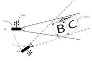
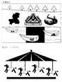
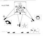
即ち、図1(A)は、本発明に於ける当該画像投影方法100を実現する為の画像投影システム100の基本的な構成の具体例を示すブロック図であって、図中、少なくとも一つのプロジェクター手段1、当該プロジェクター手段1の投射領域内2に配置されている少なくとも2つの独立した画像表示領域3、当該個々の画像表示領域3の少なくとも一つの動きを検出するモーションキャプチャー手段4及び投影画像描画制御手段5とから構成されている画像投影システム100に於いて、一つの当該プロジェクター手段1が、少なくとも選択された一つの第1の画像6を、少なくとも選択された一つの第1の画像表示領域31に投影するように操作されている状態に於いて、当該第1の画像表示領域31に投影されている当該第1の画像6上に、予め選択されている所定の動作状態61の発生が検出された場合には、当該動作状態61の発生を検出する特定の検出信号7に応答して、瞬時に(リアルタイムに)当該第1の画像表示領域31に投影されている当該第1の画像6を、当該第1の画像表示領域31とは異なる第2の画像表示領域32に移動させて、第2の画像表示領域32内で当該第1の画像6の投影を継続する様に構成されている事を特徴とする画像投影方法100を実施する為の構成を含むブロック図が示されている。Hereinafter, the configuration of a specific example of the image projection method according to the present invention will be described in detail with reference to the drawings.
That is, FIG. 1A is a block diagram showing a specific example of the basic configuration of the
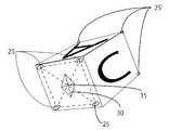
尚、図1(A)に於いては、当該プロジェクター手段1の投射領域2の3次元立体空間22内には、3個の当該画像表示領域31乃至33が配置されている例を示したものであり、又、当該3個の画像表示領域31乃至33の内で、当該第1の画像表示領域31には、画像情報として画像Cが投影されており、当該第2の画像表示領域32には、画像情報は投影されておらず、又、当該第3の画像表示領域33には、画像情報として画像Aが投影されている状態で、当該第1の画像表示領域31が点線で示す位置に変位すると言う、特定の動作状態61が発生した場合に、当該第1の画像表示領域31に投影されている当該画像Cの画像情報を当該第2の画像表示領域32に移動させて投影操作が継続される様に構成されている具体例を示している。 FIG. 1A shows an example in which three
一方、図1(B)には、上記した、当該画像投影システムに於いて、当該モーションキャプチャー手段4として、複数個、本具体例では、4個のモーションキャプチャーカメラ41乃至44が当該複数個の画像表示領域のそれぞれを実質的にカバーして監視出来る様に、当該各画像表示領域の周辺部位に、個別独立的に配置されており、当該各モーションキャプチャーカメラ41乃至44が個別に検出した、当該各画像表示領域毎の当該プロジェクター手段1の投射領域2の3次元立体空間22内に於ける3次元位置情報及び各画像表示領域毎の特定の動作状態61が発生した事を検知した特定動作状態発生検知信号7とは、適宜のハブ手段45を介して、モーションキャプチャーデータ処理手段8に伝達される様に構成されており、更には、当該投影画像描画制御手段5は、当該モーションキャプチャーデータ処理手段8から出力される当該所定の画像表示領域31に特定動作状態発生した事を検知する検知信号7に応答して、当該第1の画像表示領域31に投影されている当該第1の画像Bを当該第2の画像表示領域32に移動させて、当該第2の画像表示領域内に当該第1の画像Bを投影し、その状態を継続させると言う具体例の構成が示されている。
係る具体例に於いて、元の画像表示領域に表示されていた画像は、消滅させても良く、或いは当該画像表示を継続させるものであっても良い。
本具体例では、当該特定動作状態発生した事を検知する検知信号7を図1及び図4と図5に示す様に、当該モーションキャプチャーデータ処理手段8で発生させ、その信号を当該投影画像描画制御手段5に入力する例を示しているが、本発明に於いては、係る具体例に特定されるものではなく、当該モーションキャプチャーデータ処理手段8では、単に、特定の画像表示領域の動き状態を継続的にモニターする機能のみを付与しておき、当該特定の画像表示領域が、特定の動作状態を発生させたか否かの検知・判断手段と当該特定の動作状態発生報知手段とを当該投影画像描画制御手段5に設けて、当該投影画像描画制御手段5で、当該特定動作状態発生検知信号7を発生させるように構成したものであっても良い事は言うまでもない。
更に、本発明に於いける具体的が事例としては、例えば、一つの当該画像表示領域31を人が手に持って移動させている場合に於いて、当該人物が、当該画像表示領域31を、所定の方向に放り投げる様な動作をする事によって、それまで、当該画像表示領域31に投影されていた特定の画像情報を別の画像表示領域32に移動させるというアクション動作を実現出来る。
本発明では、更に、当該所定の画像表示領域31に投影されていた特定の画像を別の画像表示領域32に移動させる動作に同期させて、音声、音楽、チャイム等の音情報を発生させるように構成されたものであっても良い。On the other hand, in FIG. 1B, in the image projection system described above, as the motion capture means 4, a plurality of, in this example, four
In such a specific example, the image displayed in the original image display area may be erased, or the image display may be continued.
In this specific example, a
Furthermore, as a specific example in the present invention, for example, when a person moves one
In the present invention, sound information such as voice, music, and chime is generated in synchronization with an operation of moving a specific image projected on the predetermined
尚、当該図1(B)に示される本発明に係る具体例に於いては、当該プロジェクター手段1の投射領域2の3次元立体空間22内には、2個の当該画像表示領域31及び32が配置されている例を示したものであり、且つ、当該第1の画像表示領域31には、第1の画像表示領域として、矩形立方体を形成した画像表示領域を有しており、外観出来る3つの画像表示面には、それぞれA,B及びCの画像情報が、個別に投影されており、当該第2の画像表示領域32には、何らの画像情報は投影されていない状況に於いて、当該第1の画像表示領域31が、矢印61に示す方向に移動して、新たな画像表示領域3’に移動した場合に、当該第1の画像表示領域31の主要投射面に投射されていた画像情報Bを当該第2の画像表示領域32に移動させ、当該第2の画像表示領域32内に於いて、当該画像情報Bの投影処理操作を継続する様に構成された例を示している。
尚、上記具体例に於いては、当該第1の画像表示領域31の主要投射面に投射されていた画像情報Bを当該第2の画像表示領域32に移動させた場合、当該第1の画像表示領域31の主要投射面に投射されていた画像情報Bは、消滅させても良く、或いは、そのまま残留させるものであっても良く、更には、他の画像と取り換える事も可能である。1B, in the three-
In the specific example, when the image information B projected on the main projection surface of the first
処で、本発明に於いて使用される当該複数個の画像表示領域3(31、32、33・・・・・)のそれぞれは、何れも、投影面部分が略平面であって、その平面形状は、矩形、円形、多角形、楕円形、台形等を含む任意の形状を有するものであるか、或いは、当該投影面部分が3次元的立体形状を呈し、球面、球体、多角面構成体を含む任意の立体構成物で構成されている事が望ましい。
つまり、本発明に於いては、当該画像表示領域3としては、人物像、動物像、その他一般的な立体形状を有する物体の全てを対象として選択出来るのである。
更に、本発明に於いては、当該複数個の画像表示領域3(表示領域3(31、32、33・・・・・)のそれぞれは、当該プロジェクター手段1が形成する個別の投射領域22内の3次元空間23内に、任意に且つ独立して存在しており、且つ個々の当該画像表示領域3(31、32、33・・・・・)のそれぞれは、独立的に任意の方向に移動可能に構成されている事も、好ましい具体例である。By the way, each of the plurality of image display areas 3 (31, 32, 33...) Used in the present invention has a substantially flat projection surface portion, and the plane. The shape has an arbitrary shape including a rectangle, a circle, a polygon, an ellipse, a trapezoid, or the like, or the projection surface portion has a three-dimensional solid shape, and is a spherical surface, a sphere, or a polygonal structure. It is desirable that it is composed of an arbitrary three-dimensional structure including
In other words, in the present invention, the
Further, in the present invention, each of the plurality of image display areas 3 (display areas 3 (31, 32, 33...)) Is within an
一方、本発明に於ける当該複数個の画像表示領域3(31、32、33・・・・・)のそれぞれには、個別的に、当該個々の画像表示領域3(31、32、33・・・・・)の範囲並びに当該投影領域22内の3次元空間23内に於ける存在位置を表示する為に、複数個のマーカー25が付与されている事が必要である。
そして、本発明に於ける当該個々のマーカー25は、それぞれ個別に3次元位置情報を有している事が望ましい。On the other hand, each of the plurality of image display areas 3 (31, 32, 33. ..
And it is desirable that each
更に、本発明に於いては、当該モーションキャプチャー手段4を構成する一つ若しくは複数個のモーションキャプチャーカメラ41乃至44が常時、当該個々の画像表示領域3(31乃至33)毎に、当該個々の画像表示領域3(31乃至33)に配置されている当該マーカー25の存在位置を、3次元位置情報として検出し、当該個々の画像表示領域3の当該3次元位置情報をリアルタイムで当該画像投影システム100に設けられているモーションキャプチャーデータ処理手段8に報知する様に構成されている事が好ましい具体例の一つである。Furthermore, in the present invention, one or a plurality of
又、本発明に於ける当該画像投影システム100には、更に、当該モーションキャプチャーデータ処理手段8が設けられており、当該モーションキャプチャーデータ処理手段8は、当該モーションキャプチャーカメラ41乃至44が検出した、当該個々の画像表示領域3(31乃至33)毎の個々のマーカーの3次元位置情報から、当該個々の画像表示領域の当該空間領域内於ける存在位置及び当該個々の画像表示領域3(31乃至33)の画像表示領域面の形状及び/又は投射方向に対する角度等を含む画像表示領域情報26を演算処理してリアルタイムで決定する様に構成されている事が望ましい具体例の一つである。Further, the
一方、本発明に於いては、当該個々の独立した画像表示領域3(31乃至33)は、任意の時点で、任意の方向に、移動、回転、旋回、振動等の変位動作を個別に実行できる様に構成されている事が望ましい。
本発明に於ける当該画像表示領域3の個々の変位動作として、当該移動とは、当該画像表示領域3の個々を、所定の方向に所定の長さだけ並行的に移動するものであり、又、当該回転とは、当該画像表示領域3の個々を、所定の適宜の点を中心として所定の方向に、所定の角度だけ、平面的に回転移動する事を示唆するものであり、更に、当該旋回とは、当該画像表示領域3(31乃至33)の何れかにいて、当該画像表示領域3を貫通する回転軸線に沿って、所定の角度だけ、旋回させる操作をそれぞれ示している。
又、本発明に於ける当該振動とは、当該個々の独立した画像表示領域3を任意の方向に急速に上下動や左右動、揺動させる動作を示す。On the other hand, in the present invention, the individual independent image display areas 3 (31 to 33) individually perform displacement operations such as movement, rotation, turning, and vibration in an arbitrary direction at an arbitrary time. It is desirable that it is configured so that it can.
As the individual displacement operation of the
Further, the vibration in the present invention indicates an operation of rapidly moving the individual independent
又、本発明に於ける当該個々の独立した画像表示領域3(31乃至33)に於ける当該変位動作6は、任意のタイミングに於いて、適宜のプログラム等を利用して自動的若しくは手動的にそれぞれ独立的に実行されるものである。
例えば、当該画像表示領域3は、適宜の移動・変位可能な機械的装置(図示せず)に取り付けられていて、当該機械的装置を適宜のプログラムに従って、或いは、人為的入力操作によって、移動・変位させる事が可能である。
本発明に於いては、当該全ての画像表示領域3(31乃至33)に設けられている全てのマーカー25の当該3次元位置情報は、常時、リアルタイムで検出され、後述する様に、モーションキャプチャーデータ処理手段8に於いて、所定の演算処理が行われ、当該個々の画像表示領域3(31乃至33)の当該投影空間領域内於ける存在位置及び当該個々の画像表示領域3(31乃至33)の画像表示領域面の形状及び/又は投射方向に対する角度等を含む画像表示領域情報が、瞬時に且つリアルタイムで決定され、その結果が後述する投影画像描画制御手段5に送信される様に構成されている。Further, the
For example, the
In the present invention, the three-dimensional position information of all the
同様に、当該モーションキャプチャーデータ処理手段8に於いては、当該全てのマーカー25からリアルタイムに送信されて来た当該個々の画像表示領域3に関する3次元位置情報を基に、当該個々の画像表示領域3に付いて、適宜の時間差を以て適宜の差分情報を演算処理することにより、当該個々の画像表示領域3に付いての、移動或いは変位等に関する変位動作情報6を得る事が出来る。Similarly, in the motion capture data processing means 8, the individual image display area is based on the three-dimensional position information regarding the individual
本発明に於いては、後述する様に、係る変位動作情報6をリアルタイムで取得しながら、当該変位動作情報6の値を、予め定められた特定の閾値(しきい値)と比較して、当該変位動作情報6の値が、当該特定の閾値を超えたと判断された場合には、上記した様に、特定の動作状態発生検出信号7を当該モーションキャプチャーデータ処理手段8から出力させ、それが当該投影画像描画制御手段5に入力される事になる。In the present invention, as described later, while acquiring the
一方、本発明に於いては、当該投射領域2内に複数個の当該画像表示領域3(31乃至33)が配置されている場合、全ての当該各画像表示領域3(31乃至33)に対して、同一の画像情報を投影する事も可能であり、又、相互に異なる画像情報を投影する事も可能である。
更には、その一部の当該画像表示領域3に対しては、画像情報の投影を行わず、ブラインド状態にしておく事も可能である。On the other hand, in the present invention, when a plurality of the image display areas 3 (31 to 33) are arranged in the
Furthermore, it is possible to leave the
そして、本発明に於いて、例えば、図1(B)に示す様に、特定の画像表示領域3の一つである当該第1の画像表示領域31が、矢印61に示す方向に移動し変位した事に起因して、当該第1の画像表示領域31に対して当該特定の動作状態発生検出信号7が発生した場合には、当該第1の画像表示領域31にこれまで投影されていた画像情報である第1の画像情報Bを、これまでブラインド状態にあった当該第2の画像表示領域32の表示領域内に当該第1の画像情報Bを移動させ、そこに当該第1の画像情報Bを投影させ、その状態を継続させる事になる。
この場合、当該第1の画像表示領域31はブラインド状態としても良く、又、別途用意した第3の画像情報Xを投影するものであっても良い。In the present invention, for example, as shown in FIG. 1B, the first
In this case, the first
同様に、本発明に於いては、上記した画像移転操作に於いて、当該第1の画像表示領域31とは異なる第2の画像表示領域32に表示される画像は、当該第1の画像情報Bとは異なる画像情報Yであっても良い。
つまり、本発明に於いては、当該プロジェクター手段1の投射領域2内に配置されている少なくとも2つの独立した画像表示領域31乃至33のそれぞれの画像表示領域に対しては、同一若しくは相互に異なる画像が個別に投影される事も可能である。Similarly, in the present invention, in the image transfer operation described above, the image displayed in the second
That is, in the present invention, the image display areas of at least two independent
本発明に於いては、当該モーションキャプチャー手段4は、複数個のモーションキャプチャーカメラ41乃至44を含んでいる事が望ましく、特に好ましくは3個或いは3個以上のモーションキャプチャーカメラ41乃至44を含んでいるものであって、当該それぞれのモーションキャプチャーカメラ41乃至44は、それぞれが当該個々の画像表示領域31乃至33の何れかの外周面の略全域が見渡せる様な部位に分散して配置されている事が望ましい。
そして、当該それぞれのモーションキャプチャーカメラ41乃至44は、当該プロジェクター手段1と共通の原点(X=0,Y=0,Z=0)を持っている事が必要である。
一方、本発明に於ける当該マーカー25は、当該複数個の画像表示領域31乃至33のそれぞれに付いて、個別的に、当該個々の画像表示領域31乃至33に対応する個別の識別子を有しており、当該マーカー25が、当該個々の画像表示領域31乃至33に対応してそれぞれグループ分けされている事が望ましい。In the present invention, the motion capture means 4 preferably includes a plurality of
Each of the
On the other hand, the
一方、本発明に於いては、当該プロジェクター手段1により当該所定の画像表示領域31乃至33のそれぞれに対して投射される画像は動画像、アニメーション或いは静止画像であり、当該複数種類の動画像及び静止画像は、当該投影画像描画制御手段5に接続された適宜の記憶手段9内に予め記憶されている事が望ましい。
尚、本発明に於いては、3次元位置情報を取り扱うので、表示すべき当該画像は何れも2次元画像で有っても良く或いは3次元画像で有っても良いので、極めてアトラクティブな画像投影効果が得られる。On the other hand, in the present invention, the image projected onto each of the predetermined
In the present invention, since the three-dimensional position information is handled, any of the images to be displayed may be a two-dimensional image or a three-dimensional image. A projection effect is obtained.
更に、本発明においては、当該投影画像描画制御手段5は、常時、リアルタイムで、当該選択された画像表示領域31乃至33のそれぞれに対して、当該モーションキャプチャーデータ処理手段8から出力される当該選択された画像表示領域に関する位置情報及び当該画像表示領域の画像表示領域面の形状及び/又は投射方向に対する角度等の画像表示領域情報に基づいて、当該記憶手段9より選択された画像を、現時点に於ける当該選択された画像表示領域31乃至33の画像表示領域の状況に合わせた最適な画像となる様に描画処理し、当該描画処理した当該画像を当該選択された画像表示領域31乃至33に投射する様に構成されているものである。 Further, in the present invention, the projection image drawing control means 5 always outputs the selection output from the motion capture data processing means 8 for each of the selected
一方、本発明に於いては、当該一つのプロジェクター手段を使用する代わりに、図1(A)に示されている様に、複数個のプロジェクター手段1、1’が設けられている事も可能であり、当該個々のプロジェクター手段1、1’は、個別に、当該個々の独立した画像表示領域31乃至33の一部若しくは全部に、選択された個々の画像を投射する様に構成されている事も可能である。On the other hand, in the present invention, instead of using the one projector means, a plurality of projector means 1, 1 'may be provided as shown in FIG. The individual projector means 1, 1 ′ are individually configured to project selected individual images onto part or all of the individual independent
更に、本発明に於いて、当該特定の画像情報を当該所定の画像表示領域31から別の画像表示領域32に対して投影操作を移動変更する際に検出される当該変位動作は、当該個々の独立した画像表示領域31乃至33に於ける当該移動、回転、旋回、振動等に於ける移動長さ、回転角度、旋回角度で有っても良く、或いは当該移動速度、回転角速度、旋回角速度で有っても良く、或いは振動の振幅や振動回数等であっても良い。
又は、画像表示領域31乃至33の当該移動、回転、旋回等に於ける移動加速度、回転角加速度、旋回角加速度である事が望ましい。
何れにしても、上記した本発明に係る当該各処理操作、検出操作は、何れも当該画像表示領域3のそれぞれが、当該モーションキャプチャーカメラ41乃至44のキャプチャーエリア内のみにおいて有効である事は言うまでも無い。Further, in the present invention, the displacement operation detected when the specific image information is moved and changed from the predetermined
Alternatively, it is desirable that the
In any case, each of the processing operation and the detection operation according to the present invention described above is valid only in the capture area of the
此処で、本発明に於いて使用される当該モーションキャプチャー手段4とそれぞれの当該画像表示領域3に取り付けられる当該マーカー25について説明する。
本発明に於いて使用される当該マーカー25の特性或いは製造材料等は特に限定されるものではなく、赤外線を反射出来る特性を有するもので有れば、一般的に市販されている材質のマーカーを使用する事が可能である。
当該マーカー5の大きさも特に限定されるものではないが、例えば、高解像度のカメラや、赤外線カメラにより検出可能な範囲として、縦横が5mm程度の大きさを有するもので有れば使用可能であり、この程度の大きさのもので有れば、第3者からの目視による認識が出来ないので、好都合である。Here, the motion capture means 4 used in the present invention and the
The characteristics or manufacturing materials of the
The size of the
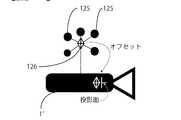
そして、本発明に於いては、当該マーカー5を選択された当該画像表示領域31乃至33のそれぞれに取り付けるものであるが、取り付け方法は、それぞれの当該画像表示領域31乃至33に対して、少なくとも3か所、好ましくは4か所張り付けるものであり、当該マーカー5の貼り付け場所は、当該それぞれの当該画像表示領域31乃至33の角部とする事が望ましい。
例えば、当該画像表示領域32の様に、画像表示領域が平面形状を有する場合には、図1(B)に示す様に、矩形形状の4つの角部に当該マーカー25を配置する事が可能であるが、例えば、当該画像表示領域31の様に、画像表示領域が立体矩形の6面体形状を有している場合には、その主たる外観面で画像情報Bが投影されている面の4隅にマーカー25を取り付けるものである。In the present invention, the
For example, when the image display area has a planar shape like the
一方、当該31に於けるその他の角部、及び外観上見えない角部に対しては、当該立体矩形6面体形状に付いての、縦、横、幅に関する長さ情報が知られていることを利用して、当該公知の補完手法を用いて、バーチャルマーカー25’を作成して添付する事が可能である。
つまり、例えばBOX状の当該画像表示領域31の底辺マーカーなどはモーションキャプチャー手段4のモーションキャプチャーカメラ41乃至44からでは撮影出来ない場所にあるので、そのような条件を補う為の手法である。
この手法で当該画像表示領域31に4点のマーカー25をつけるだけで隣接する面の頂点を疑似的に作り出す事が可能となる。
係る操作を実行する為に、例えば、モーションキャプチャーシステムに於いて一般的に使用されている“CORTEX”と称されているソフトを使用する事が出来る。On the other hand, length information about the vertical, horizontal, and width of the solid rectangular hexahedron shape is known for the other corners in 31 and corners that are not visible in appearance. Can be used to create and attach a virtual marker 25 'using the known complementing technique.
That is, for example, the bottom marker of the
With this method, it is possible to artificially create vertices of adjacent surfaces by simply attaching four
In order to execute such an operation, for example, software called “COREX” which is generally used in a motion capture system can be used.
当該それぞれのマーカー25間の相互関係に関しては、基本的には、マーカー25のつける場所が異なれば、マーカー間の距離が違うのでマーカー4点でも誤認識の可能性は低いので、同じマーカー数ででも違うグループと判断する事が可能であり、従って、マーカー25のつけ方とマーカー25の数により当該キャプチャーエリアに多数のグループを個別に認識させることが可能であるが、好ましくは、取り付けた当該画像表示領域31乃至33ごとにマーカー25をグループ分けする為に、グループ化されたマーカーグループに名前をつけ他のマーカーグループとの区別をつける事が望ましい。 Regarding the interrelationship between the
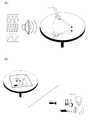
尚、本発明に於いては、当該それぞれの画像表示領域31乃至33に取り付けられたマーカー25から、当該各画像表示領域31乃至33の配置方向性と回転情報がわかるように、図2に示す様に、当該マーカーグループ25の3次元位置座標情報(XYZの座標値)をもとにセグメント30を疑似的に作成する事が望ましい具体例である。
具体的には、それぞれのマーカー25の中心点を直線で結びその交差点35上にセグメント30を作成するものである。
当該セグメント30はそれぞれのマーカー25の座標値を参照し、当該それぞれの画像表示領域31乃至33の方向情報と回転情報を検出する事が可能である。In the present invention, the
Specifically, the center point of each
The
次に、本発明に於いて使用されるモーションキャプチャー手段4の構成の一具体例について説明する。
即ち、本発明に於ける当該モーションキャプチャー手段4としては、光学式を採用する事が望ましいが、必ずしもこれに限定されるものではなく、例えば、一般的に公知となっている「磁気式」、「機械式」、「慣性センサ式」、「画像認識式」などのさまざまな方式を使用する事が可能である。
然しながら、データの精度、汎用性、システムの使い勝手、拡張性、被験者への負担(拘束性)、システム設置場所の自由度などの点を考慮すると当該「光学式」システムが優れており、結果として現在では、この方式がモーションキャプチャ−システムの主流になっている。
当該システムでは、3次元位置座標値は、当該画像表示領域3の表面にマーカ25を貼るだけで計測できる為、キャプチャする動作に制限が少なく、複数のキャプチャも可能という利点もある。Next, a specific example of the configuration of the motion capture means 4 used in the present invention will be described.
That is, as the motion capture means 4 in the present invention, it is desirable to adopt an optical system, but it is not necessarily limited to this, for example, a generally known “magnetic system”, Various methods such as “mechanical type”, “inertial sensor type”, and “image recognition type” can be used.
However, considering the data accuracy, versatility, usability of the system, expandability, burden on the subject (restraint), freedom of system installation location, etc., the “optical” system is superior. At present, this method has become the mainstream of motion capture systems.
In this system, since the three-dimensional position coordinate value can be measured simply by attaching the
一方、当該「光学式」システムの欠点としては、反射マーカが複数台のカメラから見えていなければならないという原理的な問題であり、従って、当該マーカ25が隠れてしまう状況では当該所定の座標位置データが取れないことになる。
然しながら、上記した公知のシステムの制御ソフトである“CORTEX”では、隠れたマーカの位置を他のマーカから計算し補間することも可能で、隠れ状況によっては十分に対応できるようになっている。
具体的には、一般的に使用されているモーションキャプチャーカメラ41乃至44を、投影エリアをカバーでき、且つそれぞれの当該画像表示領域31乃至33の周りをカバー出来るように設置し、X軸、Y軸、およびZ軸の原点(X=0,Y=0,Z=0)をリアルな空間でどの位置に設定するのかのキャリブレーション処理を従来公知の方法を使用して実行する。On the other hand, a disadvantage of the “optical” system is the principle problem that the reflective marker must be visible from a plurality of cameras. Therefore, in the situation where the
However, in the above-mentioned known system control software “COREX”, the position of the hidden marker can be calculated and interpolated from other markers, and can be sufficiently handled depending on the hidden situation.
Specifically,
次に、本発明に於ける当該画像投影装置100の構成に関する具体例を説明する。
即ち、本発明に係る当該画像投影装置100は、図1(A)に示す通り、少なくとも一つのプロジェクター手段1、当該プロジェクター手段1の投射領域空間2内に配置されている少なくとも2つの独立した画像表示領域3(31乃至33)、当該個々の画像表示領域3(31乃至33)の少なくとも一つの動きを検出するモーションキャプチャー手段4、当該モーションキャプチャー手段4と接続されているモーションキャプチャーデータ処理手段8、当該モーションキャプチャーデータ処理手段8及び当該プロジェクター手段1と接続されている投影画像描画制御手段5及び当該投影画像描画制御手段5に接続されている画像情報格納手段9とから構成されている画像投影システム100が示されている。Next, a specific example relating to the configuration of the
That is, the
そして、本発明に於ける当該画像投影システム100に於いて、当該モーションキャプチャー手段4は、少なくとも一つ、好ましくは複数個の当該此処の画像表示領域3(31乃至33)の周辺部に配置されているモーションキャプチャーカメラ41乃至44を含んでいる。In the
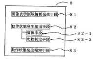
一方、本発明に於ける当該モーションキャプチャーデータ処理手段8は、図4に示す様に、当該モーションキャプチャーカメラ41乃至44により捕捉された当該それぞれの画像表示領域3(31乃至33)に配置された個々のマーカー25に於ける3次元位置情報に基づいて、当該個々の画像表示領域3(31乃至33)毎の当該空間領域23内於ける存在位置及び当該個々の画像表示領域3(31乃至33)の画像表示領域面の形状及び/又は投射方向に対する角度等を含む画像表示領域情報を演算処理してリアルタイムで決定する画像表示領域情報発生手段81と、当該個々の画像表示領域3(31乃至33)に関する当該画像表示領域情報に基づいて、当該投射されている画像上に、予め選択されている所定の動作状態が発生しているか否かをリアルタイムで演算処理して決定する動作状態発生検出手段82と、当該投射されている画像表示領域3(31乃至33)に投影されている当該画像上に、予め選択されている所定の動作状態の発生が検出された場合には、当該動作状態の発生を報知する特定の検出信号7を出力する動作状態発生報知手段83とが設けられている。On the other hand, the motion capture data processing means 8 in the present invention is arranged in each of the image display areas 3 (31 to 33) captured by the
又、本発明に於ける当該投影画像描画制御手段5には、図5に示す様に、当該プロジェクター手段選択手段51と、当該複数個の画像表示領域3(31乃至33)より選択された少なくとも一つの画像表示領域を選択する画像表示領域選択手段52と、当該画像情報格納手段9から投射すべき少なくとも一つの画像情報を選択する画像情報選択手段53と、当該選択された一つの画像表示領域に関する当該画像表示領域情報を当該モーションキャプチャーデータ処理手段8より取り込む画像表示領域情報取得手段54と、当該選択された投射すべき少なくとも一つの画像情報を、当該画像表示領域情報を基にして、当該選択された一つの画像表示領域内に投影するに適した画像情報に修正する描画処理手段55と、当該描画処理手段55により修正された当該選択された画像情報を当該選択されたプロジェクター手段1を介して、当該選択された画像表示領域3(31乃至33)に投射する様に指示を行う投射指示手段56と、当該モーションキャプチャーデータ処理手段8から出力される、当該選択された一つの画像表示領域に於ける所定の動作状態の発生を報知する当該特定の検出信号7を検知した場合には、当該特定の検出信号7に応答して、瞬時に(リアルタイムに)、当該画像が選択投影されている画像表示領域(第1の画像表示領域31)とは異なる別の画像表示領域(第2の画像表示領域32)を別途選択する別の画像表示領域選択手段57と、当該別途選択された当該画像表示領域(第2の画像表示領域32)に関する画像表示領域情報を当該モーションキャプチャーデータ処理手段8から取り込む異なる画像表示領域情報取り込み手段58と、当該取り込まれた、別途選択された当該画像表示領域(第2の画像表示領域32)に関する画像表示領域情報に基づいて、当該選択投影されている画像を、当該別途選択された画像表示領域(第2の画像表示領域32)内に投影するに適した画像情報に修正する別の描画処理手段59と、当該別の描画処理手段59により修正された当該選択された画像情報を、当該選択されたプロジェクター手段1を介して、瞬時に(リアルタイムに)、当該別途選択された画像表示領域(第2の画像表示領域32)に投射する様に指示を行う別の投射指示手段60、とを有するものである。Further, as shown in FIG. 5, the projection image drawing control means 5 in the present invention includes at least the projector means selection means 51 and at least one selected from the plurality of image display areas 3 (31 to 33). Image display area selection means 52 for selecting one image display area, image information selection means 53 for selecting at least one image information to be projected from the image information storage means 9, and the selected one image display area The image display area information acquisition means 54 that captures the image display area information related to the image from the motion capture data processing means 8 and the selected at least one image information to be projected, based on the image display area information, A drawing processing unit 55 that corrects image information suitable for projection within one selected image display area, and the drawing processing unit 55 A projection instruction means 56 for instructing the corrected image information to be projected onto the selected image display area 3 (31 to 33) via the selected projector means 1, and the motion When the
本発明に於いては、当該元の画像表示領域(第1の画像表示領域31)に対しては、元の画像(第1の画像B)の投射を停止しても良く、或は継続させても良く、或は別の画像Xを投射するものであっても良い。
更に、本発明に於いては、当該画像を特定の画像表示領域(第1の画像表示領域31)に対して投射する様に指示を行う投射指示手段56と、当該画像を別の特定の画像表示領域(第2の画像表示領域32)に対して投射する様に指示を行う当該別の投射指示手段60は、別々に独立して設けられていなくともよく、同一の手段であっても良い。
又、当該画像表示領域情報取得手段54と当該異なる画像表示領域情報取り込み手段58も別々に独立して設けられたものであっても良く或いは同一の手段であっても良い。In the present invention, the projection of the original image (first image B) may be stopped or continued for the original image display area (first image display area 31). Alternatively, another image X may be projected.
Further, in the present invention, the projection instruction means 56 for instructing to project the image onto the specific image display area (first image display area 31), and the image as another specific image. The other projection instruction means 60 for giving an instruction to project on the display area (second image display area 32) may not be provided separately and may be the same means. .
Further, the image display area information acquisition means 54 and the different image display area information acquisition means 58 may be provided separately and independently, or may be the same means.
一方、本発明に於いては、当該投射領域2内に3個以上の当該画像表示領域3が配置されている場合において、当該画像情報の移動が考慮されている少なくとも2つの当該画像表示領域3に対する同一或いは異なる画像情報の投射操作は、何らの影響を与えるものではなく、予め定められた手順に従って、別途独立的に投射操作が継続されるものである。
又、本発明に於いては、当該第1の画像表示領域31に、所定の動作状態が発生し、当該第1の画像表示領域31に投射されている第1の画像情報を当該第2の画像表示領域32に移動させて、投射を継続する場合、当該第2の画像表示領域32は、一つに限られるものではなく、複数個の別の画像表示領域33にも移動同時に或いは所定のタイミングを介してシリアルに移動させる事も出来る。On the other hand, in the present invention, when three or more
In the present invention, a predetermined operation state occurs in the first
一方、本発明に於いては、本システムにおいて投影できる画像の種類は、上記した通り、静止画、アニメーション、動画及び外部からのビデオ映像等が投影可能である。
そして、本発明に於いては、当該静止画、アニメーション或いは当該動画等は3Dバーチャルソフト内でファイル化して投影するものであり、又、当該外部からの映像はシステムの搭載されているビデオボードで圧縮され、例えば、MPEG2の形式に変換され3Dバーチャルソフトに転送され、リアルタイムに投影することが可能となる。(尚、MPEG2圧縮時に1F程度のディレイが発生する。)On the other hand, in the present invention, as described above, the types of images that can be projected in this system can project still images, animations, moving images, external video images, and the like.
In the present invention, the still image, animation, or moving image is projected as a file in 3D virtual software, and the video from the outside is a video board on which the system is mounted. It is compressed, converted into, for example, MPEG2 format, transferred to 3D virtual software, and can be projected in real time. (Note that a delay of about 1F occurs during MPEG2 compression.)
一方、本発明に於ける当該画像の描画方法は、特に限定されるものではないが、例えば、図3(A)に例示する様に、3Dバーチャルソフトで画像の描画開始位置と終了位置をモーションキャプチャー手段4からリアルタイムに流れてきたマーカー25の座標値を参照し、3Dバーチャルソフト上の座標値に変換し、変換された座標値をもとに描画する。
例えば、投影する画像が四角形の画像の場合、図3(B)に示す様に、
被投影体のマーカー(1)と3Dバーチャルソフト上の座標値(1)
被投影体のマーカー(2)と3Dバーチャルソフト上の座標値(2)
被投影体のマーカー(3)と3Dバーチャルソフト上の座標値(3)
被投影体のマーカー(4)と3Dバーチャルソフト上の座標値(4)
上記のように座標値の変換が行われその座標値を起点、終点としてソフトが画像を描画する。On the other hand, the drawing method of the image in the present invention is not particularly limited. For example, as illustrated in FIG. 3A, the drawing start position and the end position of the image are moved with the 3D virtual software. The coordinate value of the
For example, when the image to be projected is a square image, as shown in FIG.
Projector marker (1) and coordinate values on 3D virtual software (1)
Projector marker (2) and coordinate values on 3D virtual software (2)
Projector marker (3) and coordinate values on 3D virtual software (3)
Projector marker (4) and coordinate values on 3D virtual software (4)
As described above, the coordinate values are converted, and the software draws an image using the coordinate values as the start point and the end point.
本発明に於ける当該動体状態の被投影体である画像表示領域3への投影技術に関して付言するならば、従来公知の殆どのプロジェクションマッピングでは被投影体つまり画像表示領域3は動いているものではなく静体物である事が前提となっており、従って、当該投影される画像は動かない被投影体つまり画像表示領域3に合わせこむようにし、描画機側で再生させると決められたアニメーションを投影する技術でしかなかったのが実情である。
従って、従来の技術に於いては、当該投影される画像を当該被投影体につまり画像表示領域3に対して再生するタイミングが、プロジェクションマッピングが開始されるタイミングに固定されるという欠点が存在した。If it adds about the projection technique to the image display area |
Therefore, in the prior art, there is a drawback in that the timing for reproducing the projected image on the projection object, that is, the
然しながら、本発明のシステムはそのような制約を受けることはなく、3Dバーチャルソフトで被投影体つまり当該画像表示領域3ごとに投影する画像を持つことが出来、尚且つ、その画像を再生するタイミングをその投影される画像ごとに再生するタイミングのタイマーをもち、任意にタイミングで再生を開始できると言う作用効果を発揮する事が可能となる。
従来に於ける投影画像の種類も、通常のプロジェクションマッピングでは投影される画像は2次元の映像であるが、本発明に於いては、3Dバーチャルソフトで作成された3次元画像を使用する事が可能となる他、当該被投影体つまり当該画像表示領域3が静体状態、固定されている必要性がなく、動いていても、所望の画像情報を所定の選択された被投影体つまり当該画像表示領域3に投影することができる。However, the system of the present invention is not subject to such restrictions, and can have an image to be projected for each projection object, that is, the
In the conventional projection mapping, the projected image is a two-dimensional image in the normal projection mapping. However, in the present invention, a three-dimensional image created by 3D virtual software may be used. In addition to the above, it is not necessary that the projection object, that is, the
そして、本発明に於ける当該画像表示システム100に於いては、当該モーションキャプチャー手段4との連携によって、多面的な画像表示が可能になっている。
即ち、当該モーションキャプチャー手段4からおくられてくるデータは、当該マーカー25のX軸、Y軸、Z軸の3次元座標値を3Dバーチャルソフトが処理して3次元のCGを描画し、当該座標値の変化に追随して被投影体で有る当該画像表示領域3に投影する画像の形状をリアルタイムに当該画像表示領域3の形状に合わせて変化させることが出来るのである。
つまり、本発明に於いては、投影する為に必要とする画像コンテンツの数を複数種、多数持つ事が可能となる。In the
That is, the data sent from the motion capture means 4 is obtained by processing the 3D coordinate values of the X axis, the Y axis, and the Z axis of the
That is, in the present invention, it is possible to have a plurality of types and a large number of image contents necessary for projection.
この点が既存のプロジェクションマッピングとの大きな相違点である。
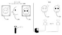
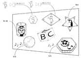
例えば、図6(A)に示す様に、従来の投影システムに於いて、投影する画像がアニメーションである場合、本発明の一具体例では、図6(B)に示す様に、被投影体である第1の画像表示領域31と別の被投影体ある第2の画像表示領域32とが相互に近づいた場合、(例えば、当該マーカー25の距離間が設定したしきい値より短くなった時)当該第1の画像表示領域31がアニメーションの前編を再生し、当該第2の画像表示領域32がアニメーションの後編を再生するという当該画像表示領域3を変えて、時間差で投影することがプログラミングで可能になる。
再生投射対象の当該画像表示領域3の数には、特に理論的には制限がないがCPUの演算処理に委ねられるところが大きい。This is a major difference from existing projection mapping.
For example, as shown in FIG. 6A, in the conventional projection system, when the image to be projected is an animation, in one specific example of the present invention, as shown in FIG. When the first
The number of the
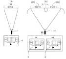
此処で、既存のプロジェクションマッピングと本発明に係るリアルタイム変化プロジェクションマッピングの違いを、図面を参照しながら説明するならば、当該既存のプロジェクションマッピングに於いては、図7(A)に示す様に、当該画像表示領域は固定されており、又、当該プロジェクター手段1も固定されており、更には、使用される投影画像は2次元画像情報に限られている。
一方、本発明に於ける当該画像表示システム100に於いては、図7(B)に示す様に、当該画像表示領域3は任意の方向に移動、回転、旋回が可能であり、又、当該プロジェクター手段1も固定されている場合と後述する様に、任意の方向に移動・変位可能となっており、更には、使用される投影画像は3次元画像情報を使用してリアルタイムで描画処理、投影操作処理が実行可能である。Here, if the difference between the existing projection mapping and the real-time change projection mapping according to the present invention will be described with reference to the drawings, in the existing projection mapping, as shown in FIG. The image display area is fixed, the projector means 1 is also fixed, and the projection image used is limited to two-dimensional image information.
On the other hand, in the
その為、本発明に於いては、リアルタイム変化に対応するプロジェクションマッピングを成立させる上で重要な要素となるのが現実の空間と3Dバーチャルソフトのスケール間を合わせるキャリブレーション操作が非常に重要な調整方法になります。
つまり、リアルな空間と3Dの仮想の空間の距離や方向などの値を一致させるキャリブレーション操作が必要となる。
本発明に於ける当該キャリブレーションに必要な要素としては、例えば、
(1)投影体と被投影体との距離と角度
(2)投影する投影体の画角サイズ
等であり、まずは、当該投影体と当該被投影体つまり画像表示領域3との距離間と角度を3Dバーチャルソフト内の投影体(VRカメラ)と被投影体(VR空間上のマーカー25)の距離間と角度合わせこむ必要がある。Therefore, in the present invention, a calibration operation that matches the real space and the scale of the 3D virtual software is an important factor in establishing projection mapping corresponding to real-time changes. Will be the way.
That is, a calibration operation is required to match values such as the distance and direction between the real space and the 3D virtual space.
As an element necessary for the calibration in the present invention, for example,
(1) Distance and angle between the projection body and the projection object (2) The angle of view size of the projection object to be projected, etc. Must be angle-adjusted with the distance between the projection object (VR camera) and the projection object (
3Dバーチャルソフト上のVRカメラは3Dバーチャルソフト上の見え方アングルと画角サイズを操作する機能であり、当該プロジェクター1の投影する画像は、当該VRカメラが見えている画像となる。
そして、当該距離間に関しては、当該モーションキャプチャー手段4のスケールの変換が必要となり、当該モーションキャプチャー手段4の距離間と3Dバーチャルソフトのスケール値が異なるため、当該モーションキャプチャー手段4のスケールを1/10倍にする。
この際、角度情報は変換する必要はない。
一方、投影する投影体の画角サイズに関しては、距離や回転情報はモーションキャプチャー手段4から送られてくる座標値を基に、現実の空間に合わせて3Dバーチャルソフトに同期させることができるが、投影するプロジェクター1の画角サイズ情報はマーカー25の座標値とは関係ないので送られて来ない。The VR camera on the 3D virtual software has a function of manipulating the viewing angle and the view angle size on the 3D virtual software, and the image projected by the
For the distance, the scale of the motion capture means 4 needs to be converted, and the scale value of the motion capture means 4 is different from the distance between the motion capture means 4 and the scale value of the 3D virtual software. 10 times.
At this time, the angle information need not be converted.
On the other hand, regarding the angle of view size of the projection object to be projected, the distance and rotation information can be synchronized with the 3D virtual software according to the actual space based on the coordinate values sent from the motion capture means 4, The angle-of-view size information of the
一方、当該プロジェクター1の投影する画角のサイズを求めて3Dバーチャルソフトに投影する画像の画角のサイズを設定する必要がある。
3Dバーチャルソフト上でプロジェクターをカメラとして置き換えているので3Dバーチャルソフト上のカメラから見える範囲がプロジェクターの投影範囲となる。
又、画角サイズの出し方に付いて説明するならば、当該被投影面(原点になる面)とプロジェクター1までの距離を測り、図8に示す様に、投影している映像の幅Wを測定する。
当該測定した数値を三角関数により求め画角サイズをFOVを出す。On the other hand, it is necessary to determine the angle of view of the image projected by the
Since the projector is replaced as a camera on the 3D virtual software, the range visible from the camera on the 3D virtual software is the projection range of the projector.
Further, to explain how to obtain the angle of view, the distance from the projection surface (the surface to be the origin) to the
The measured numerical value is obtained by a trigonometric function, and the field angle size is output as FOV.
次に、本発明に於いて、加速度計算を利用して当該第1の画像表示領域31に投影されている画像が当該第2の画像表示領域32に移動するときの仕組みに付いて説明するならば、基本的には、当該第1の画像表示領域31のマーカー25の移動距離をもとに加速度を計算することになる。
つまり、当該マーカー25の移動幅を単位時間の早さにおきかえる。
誤動作を防ぐため上限と下限のしきい値を設定する事が望ましい。
そして、当該上限よりも早ければ誤動作だと判断し、又、当該下限よりも遅ければ誤動作だと判断する。Next, in the present invention, a mechanism when an image projected on the first
That is, the movement width of the
It is desirable to set upper and lower thresholds to prevent malfunctions.
If it is earlier than the upper limit, it is determined as a malfunction, and if it is later than the lower limit, it is determined as a malfunction.
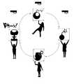
例えば、当該しきい値を、人が特定の被投影体である当該第1の画像表示領域31を立体矩形状の箱体物である場合に、当該箱体物有る方向に放り投げる際の感覚のスピード近傍の値に設定する。
更に、当該設定スピードは調整可能である。
つまり、本発明に係る当該画像表示方法或いはそのシステム100に於ける一つのアトラクティブなデモンストレーションとして、例えば、ステージ上で、演技者が、矩形状立方体(6面体)状の箱体物を手に持って、左右、上下に揺らせたり、回転させたり、或いは円を描く様に、動かしたりしている場合に、当該箱体物の一つの面、或いは複数の面(つまり、当該第1の画像表示領域31)に、適宜の画像情報を、当該プロジェクター手段1から同時に投射させておき、ある時点で、当該演技者が当該箱体物を空中に放り投げる様な動作をして、瞬間的に、当該箱体物に急激な移動動作を与えると、当該体物の当該面に投影されていた当該画像情報が、瞬時に且つリアルタイムで、別の画像表示領域3(例えば当該第2の画像表示領域32)の表面の適宜の部位に移動して、そこで、継続的に当該画像情報の投射が継続される様に設定する事が出来る。
本発明では、この様なパフォーマンスを随時、繰り返して実演する事が可能である。For example, when the first
Further, the set speed can be adjusted.
That is, as an attractive demonstration in the image display method or the
In the present invention, such a performance can be repeatedly demonstrated at any time.
本発明に於ける当該画像表示システム100に於いては、当該第1の画像表示領域31と当該第2の画像表示領域32のアスペクト比率が同じでない場合には、当該第1の画像表示領域31から当該第2の画像表示領域32への移動時間中にアスペクトの補正プログラミングを実施する事が望ましい。
更には、本発明に於いては、当該第1の画像表示領域31の頂点と当該第2の画像表示領域32の頂点の整合性を取り、移動先の画像の方向性が変わらないようにプログラミングする事も好ましい具体例である。
例えば、当該第1の画像表示領域3が四角形の場合、当該第1の画像表示領域31の頂点1、2、3、4が当該第2の画像表示領域32の頂点1、2、3、4へ移動するようにプログラミングする事になる。In the
Furthermore, in the present invention, programming is performed so that the apex of the first
For example, when the first
又、本発明に於いては、当該画像の移動に関しては、動体状態の当該第1の画像表示領域31から動体状態の当該第2の画像表示領域32への移動が可能であると同時に、動体状態の当該第1の画像表示領域31から静体状態の当該第3の画像表示領域33への移動も可能である。
尚、当該移動先の画像表示領域は動体であっても静止状態であってもプログラミング次第でどちらでも実施可能である。
本発明に係る当該画像表示システムに於いては、例えば、モーションキャプチャー手段4からリアルタイムに受信したマーカー25の座標値をもとにプログラミングした数値をもとに、当該各マーカー25の座標値を利用した加速度計算をおこない、動いている画像表示領域31から動いている画像表示領域33へ移動する画像をマッピングすると言う、プロジェクター手段1に接続されたコンピューターが実行可能なプログラムを提供する事も出来る。In the present invention, regarding the movement of the image, the moving object state can be moved from the first
It should be noted that the image display area of the moving destination can be implemented depending on programming regardless of whether it is a moving object or a stationary state.
In the image display system according to the present invention, for example, the coordinate value of each
通常は、当該プロジェクター手段1から投影される画像は2次元の平面の映像であるが、本発明に於いては3次元の画像情報の投影が可能となる。
つまり、当該モーションキャプチャー手段4からの座標値はマーカー25ごとにXYZの座標を持っているので3次元オブジェクトの投影が可能となる。
既にある技術としての画像認識では奥行きを正確に検出することは困難である。
本発明においては、ミリ単位での検出が可能であるため当該画像表示領域3に正確に所望の画像情報をマッピングできる。
即ち、従来公知のプロジェクションマッピングに於いては、キャリブレーションを実行するに際しては、被投影体に対してミリ単位のマッピングの調整が必要であったが、本発明に於ける当該投影システムに於いては、当該マーカー25を当該スクリーン手段つまり、画像表示領域3に取り付けるだけで、正確な座標情報が取得できるので、当該キャリブレーションに関する操作や作業が簡便化され非常に少ない手間で済むので、作業効率が改善されるとい優れた作用効果も発揮される。Normally, the image projected from the projector means 1 is a two-dimensional plane image, but in the present invention, it is possible to project three-dimensional image information.
That is, since the coordinate value from the motion capture means 4 has XYZ coordinates for each
It is difficult to accurately detect depth by image recognition as an existing technology.
In the present invention, detection in millimeter units is possible, so that desired image information can be accurately mapped to the
That is, in the conventionally known projection mapping, when calibration is performed, it is necessary to adjust the mapping in millimeter units with respect to the projection target. In the projection system according to the present invention, however, Since the accurate coordinate information can be acquired simply by attaching the
更に、本発明に於いては、当該プロジェクター手段1を動かしながら当該画像表示領域3に画像をマッピングするプロジェクターに接続されたコンピューターが実行可能なプログラムを提供出来る。
更に、本発明に於いては、当該モーションキャプチャー41乃至44からのマーカー25の座標値情報から当該プロジェクター手段1と当該画像表示領域3の距離と投影体の方向、角度情報をリアルタイムに検出することにより当該プロジェクター手段1及び当該画像表示領域3が双方とも動いていても当該画像表示領域3に投影されるテクスチャーを当該画像表示領域3の形状に合わせた画像をリアルタイムに変形させてマッピングさせることが可能である。
つまり、従来のプロジェクションマッピングは、当該プロジェクター手段1を固定して当該画像表示領域3まで投影するものであるが、当該プロジェクター手段1を固定しなければ正確な場所へのマッピングが出来ないからであった。
本発明に於ける当該画像表示システム100は.当該プロジェクター手段1’にもマーカー125をつけることにより当該プロジェクター手段1’を動かしながらでもマッピングが可能になる。Furthermore, in the present invention, it is possible to provide a program executable by a computer connected to a projector that maps an image to the
Furthermore, in the present invention, the distance between the projector means 1 and the
That is, in the conventional projection mapping, the
The
本発明に於ける当該画像表示装置100に於いては、更に、図4に示す様に、当該所定の画像表示領域3(31乃至33)に現在投射されている画像上に、予め選択されている所定の動作状態が発生しているか否かをリアルタイムで検出する動作状態発生検出手段82は、当該画像表示領域3が、平面的に若しくは立体的に移動、回転或は旋回の少なくとも何れかの変位動作の程度を当該画像表示領域情報に基づいてリアルタイムに演算して求める演算手段82−1と、当該求められた当該画像表示領域の変位動作が、予め設定されている所定の閾値(しきい値)を超えているか否かを判断する比較判定手段82−2とから構成されている。
一方、本発明に於ける当該画像表示領域3の変位動作は、当該画像表示領域3に於ける変位動作の加速度である事が好まし具体例の一つである。In the
On the other hand, the displacement operation of the
次に、本発明に於いて使用される当該画像表示システム100の好ましい具体例の構成例を、図面を参照しながら詳細に説明する。
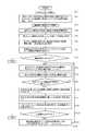
即ち、図9は、本発明に係る当該画像表示システム100の一具体例の構成を示すフローチャートであって、同図中には、少なくとも一つのプロジェクター手段1、当該プロジェクター手段1の投射領域空間23内に配置されている少なくとも2つの独立した画像表示領域3(31乃至33)、当該個々の画像表示領域3(31乃至33)の少なくとも一つの動きを検出するモーションキャプチャー手段4、モーションキャプチャーデータ処理手段8及び投影画像描画制御手段5とから構成されている画像投影システム100に於いて、
使用される当該プロジェクター手段1を選択する第21の工程(S−21)、
当該プロジェクター手段1の投射領域空間23内に配置されている当該全ての画像表示領域3(31乃至33)の当該投射領域空間23内に於ける3次元位置情報を、当該全ての画像表示領域3(31乃至33)に設けられているマーカー25と当該モーションキャプチャーデータ処理手段8に接続されているモーションキャプチャーカメラ41乃至44を介して検出する第22の工程(S−22)、
当該プロジェクター手段4の投射領域空間23内に配置されている当該画像表示領域3(31乃至33)の少なくとも一つを選択する第23の工程(S−23)、
当該選択された画像表示領域3(第1の画像表示領域31)に関する、当該次元位置データを使用して、当該選択された画像表示領域3(第1の画像表示領域31)の当該投射領域空間23内に配置されている存在位置及び当該画像表示領域面の形状及び/又は投射方向に対する角度等の画像表示領域面情報をリアルタイムで表示する第24の工程(S−24)、
当該選択された少なくとも一つの画像表示領域(第1の画像表示領域31)に対して投影すべき少なくとも一つの画像を選択する第25の工程(S−25)、
当該選択された投射すべき画像を、当該投影画像描画制御手段5により、当該選択された画像表示領域(第1の画像表示領域31)の当該画像表示領域面情報に基づいて、当該選択された画像表示領域31に投影するに適した画像情報に修正する為の描画処理を行う第26の工程(S−26)(尚、選択されていない他の、画像表示領域に対しては、画像投影は行わないか、既に別の画像が投影されている場合には、それに干渉はしない。)
当該選択されて、当該投影画像描画制御手段5により修正描画処理された修正投射画像を、当該プロジェクター手段1を介して、当該選択された画像表示領域(第1の画像表示領域31)に投射する第27の工程(S−27)、
当該描画処理された当該画像が投射されている当該選択された画像表示領域31の当該投射領域空間23内に於ける3次元位置情報を、当該モーションキャプチャー手段4を介してリアルタイムでモニターする第28の工程(S−28)、
画像表示領域31於ける当該投影画像の3次元位置情報から、当該投影画像に所定の動作状態61が発生しているか否かを検出する第29の工程(S−29)、
当該画像表示領域31に関して当該所定の動作状態61が発生した場合、当該所定の動作状態61が予め設定されているしきい値を超えているか否かを判断する第30の工程(S−30)、
当該画像表示領域(第1の画像表示領域31)に関する動作状態61が予め設定されているしきい値を超えている場合には、当該選択されている画像が投射されている当該画像表示領域(第1の画像表示領域31)とは異なる、当該プロジェクター手段1の当該投射領域空間23内に配置されている他の画像表示領域3(第2の画像表示領域32)を選択する第31の工程(S−31)、
当該選択された他の画像表示領域3(第2の画像表示領域32)に関する当該画像表示領域面情報を当該モーションキャプチャーデータ処理手段8から選択する第32の工程(S−32)、
当該選択された他の画像表示領域3(第2の画像表示領域32)に関する当該画像表示領域面情報に基づいて、当該画像表示領域(第1の画像表示領域31)に投影されている当該修正投射画像を、当該投影画像描画制御手段5により、当該選択された他の画像表示領域(第2の画像表示領域32)に投影するに適した画像情報に修正する為の再描画処理を行う第33の工程(S−33)、
当該画像表示領域(第1の画像表示領域31)に対する当該先の修正投射画像の投射操作を中止し、当該選択された他の画像表示領域(第2の画像表示領域32)に対して、新たに描画処理された再修正画像を投射する第34の工程(S−34)、
上記各工程を繰り返す第35の工程(S−35)、
と、で構成されている画像投影システム100が示されている。Next, a configuration example of a preferable specific example of the
That is, FIG. 9 is a flowchart showing the configuration of a specific example of the
A twenty-first step (S-21) for selecting the projector means 1 to be used;
The three-dimensional position information in the
A 23rd step (S-23) for selecting at least one of the image display areas 3 (31 to 33) arranged in the
The projection area space of the selected image display area 3 (first image display area 31) using the dimension position data relating to the selected image display area 3 (first image display area 31). A 24th step (S-24) for displaying in real time image display area surface information such as an existing position arranged in the
A twenty-fifth step (S-25) for selecting at least one image to be projected on the selected at least one image display region (first image display region 31);
The selected image to be projected is selected by the projection image drawing control means 5 based on the image display area surface information of the selected image display area (first image display area 31). A twenty-sixth step (S-26) for performing a drawing process for correcting image information suitable for projection on the image display area 31 (in addition, image projection is performed for other image display areas not selected. Or do not interfere with another image that has already been projected.)
The selected projection image that has been selected and subjected to the correction drawing process by the projection image
A 28th monitor for monitoring, in real time, the three-dimensional position information in the
A 29th step (S-29) of detecting whether or not a
A thirtieth step (S-30) of determining whether or not the
When the
A thirty-second step (S-32) of selecting, from the motion capture data processing means 8, the image display area surface information relating to the other selected image display area 3 (second image display area 32);
The correction projected on the image display area (first image display area 31) based on the image display area surface information regarding the selected other image display area 3 (second image display area 32). The projection image drawing control means 5 performs redrawing processing for correcting the projection image into image information suitable for projecting to the selected other image display region (second image display region 32). 33 steps (S-33),
The projection operation of the previous modified projection image on the image display area (first image display area 31) is stopped, and a new operation is performed on the selected other image display area (second image display area 32). A thirty-fourth step (S-34) of projecting the re-corrected image drawn on
A 35th step (S-35) in which the above steps are repeated,
The
更に、本発明に於いては、上記の画像投影システム100をコンピューターによる制御操作で全てが自動的にプログラミング処理されて実行されるものであり、従って、本発明に於ける更なる態様としては、上記した当該第1の工程乃至第18の工程の各機能をコンピューターで実現させる様に構成した事を特徴とする画像投影システム用プログラム100である。
本発明に於いては、上記した通り、当該プロジェクター手段1は一つでなくとも良く、2個或いはそれ以上の当該プロジェクター手段1、1‘、1“を組み合わせて使用する事が可能である。
例えば、当該プロジェクター手段1の数が増える事によって、投影する画像の数やその種類が増加し、それにより、複数個の当該画像表示領域3の数も増加させる事が可能となると同時に、一つの当該画像表示領域3に同時に組み合わせて投影される相互に異なる画像の数も増加させる事が可能となる。
又、例えば、複数個の当該プロジェクター手段1,1’を使用することにより、従来表現出来なかった、移動行為を組み合わせて、会場の雰囲気を盛り上げる演出が可能となる。Furthermore, in the present invention, the
In the present invention, as described above, the number of the projector means 1 is not necessarily one, and two or more projector means 1, 1 ′, 1 ″ can be used in combination.
For example, when the number of the projector means 1 is increased, the number and types of images to be projected are increased, whereby the number of the plurality of
In addition, for example, by using a plurality of the projector means 1 and 1 ′, it is possible to produce an atmosphere that enhances the atmosphere of the venue by combining moving actions that could not be expressed conventionally.
次に、本発明に係る当該画像投影方法に関する別の具体例を、図面を参照しながら詳細に説明する。
即ち、本発明に係る別の具体例は、基本的には、上記した具体例の中で、任意な方向に任意の速度で移動する画像表示領域の特定の画像表示面に、当該所定のプロジェクター手段から、所定の画像を当該画像表示領域の動きに完全に同期して追随しながら、確実に表示する様に構成した画像表示方法及びそのシステムである。
より具体的には、図1に示されている通り、少なくとも一つのプロジェクター手段1、当該プロジェクター手段1の投射領域2内に配置されている少なくとも1つの独立した移動可能に構成された画像表示領域3、当該画像表示領域3の動きを検出するモーションキャプチャー手段4及び投影画像描画制御手段5とから構成されている画像投影システム100に於いて、当該プロジェクター手段1は、少なくとも選択された一つの画像6を、当該画像表示領域3内に投影すると共に、当該画像表示領域3の移動動作に追随して、当該画像6が当該画像表示領域3に投影される様に移動する様に構成されている事を特徴とする画像投影方法或いはそのシステム100である。Next, another specific example relating to the image projection method according to the present invention will be described in detail with reference to the drawings.
That is, another specific example according to the present invention is basically the predetermined projector on a specific image display surface of an image display area that moves in an arbitrary direction at an arbitrary speed in the specific examples described above. An image display method and a system configured to display a predetermined image reliably while following a movement of the image display region in complete synchronization with the means.
More specifically, as shown in FIG. 1, at least one
つまり、図1(B)で示されている通り、本具体例に於いては、第1の段階で当該プロジェクター1が第1の位置31に配置されている当該第1の画像表示領域3(31)の画像表示領域面に例えばB或いはCの画像を投影して表示している場合に於いて。当該第1の画像表示領域3が第2の位置33に移動した場合でも、当該第1の画像表示領域3(33)の当該画像表示面には、同じ画像が投影される様に構成されているのである。That is, as shown in FIG. 1B, in this specific example, the first image display area 3 (in which the
ここで、本具体例での特徴的な技術構成を説明するならば、上記した具体例でも同じことが実行されているものであるが、当該独立した移動可能に構成された画像表示領域3は、当該プロジェクター手段1の投射領域2よりも小さい投射領域を有するものである事が必要であり、且つ当該画像表示領域3は、当該プロジェクター手段1の投射領域2内を自由に移動、回転、旋回、振動等の動作を自動的或いは手動で行う事が可能である様に構成されているものである。Here, if the characteristic technical configuration in this specific example is described, the same is executed in the above specific example, but the
又、本具体例に於いては、当該プロジェクター手段1の投射領域2内に移動可能に配置される当該画像表示領域3は1つに限定されるものではなく、複数個配置されるものであってもよく、その形状は、前記した具体例と同様に投影面部分が平面であってもよく、立体的であってもよいのであり、当該投影面部分が平面である場合には、その平面形状は、矩形、円形、多角形、楕円形、台形等を含む任意の形状を有するものであっても良く、或いは、当該投影面部分が3次元的立体形状を呈し、球面、球体、多角面構成体を含む任意の立体構成物で構成されているものであっても良い。In this specific example, the
更に、本具体例に於いては、当該それぞれの画像表示領域3には、同一の画像を投影する様に構成されているものであっても良く或いは、当該それぞれの画像表示領域3に個別に相互に異なる画像を投影する様にしたものであっても良い。
又、本発明に於ける上記具体例を含む具体例に於いては、それぞれの画像表示領域3に投影される画像は、動画であっても良く、静止画像であっても良く、更にその画像ソースとしては、適宜の記憶媒体から抽出した当該画像であっても良く、或いは、適宜のカメラ画像、ムービー画像、或いはテレビ画像や、携帯電話、スマートフォンを介してダウンロードされる適宜の画像であっても良い。Further, in this specific example, each
In the specific examples including the specific examples in the present invention, the image projected on each
つまり、本具体例を、感覚的に把握する為に、図23を参照して更に詳細に説明するならば、従来のプロジェクター手段1による特定画像の投影方法は、当該プロジェクター手段1の投影領域2の範囲と合致する大きさのスクリーンである画像表示領域3−0に対して、一つの画像を投影するシステムとなっているのに対し、本発明に於いては、図23に示す様に、当該プロジェクター手段1は、自己の投射領域2内に一つ或いは相互に独立した複数個の画像投影領域ウインドーW1〜W3を形成すると共に、当該各画像投影領域ウインドーW1〜W3を、当該それぞれの移動可能な画像表示領域3−1、3−2、3−3と対応させており、且つ当該それぞれの画像投影領域ウインドーW1〜W3は、個々に対応する当該画像表示領域3−1、3−2、3−3に適合する様に描画処理された特定の画像が、個別に投影される様に構成されており、更に、当該各ウインドーW1〜W3は、それぞれ対応する個別の画像表示領域3−1、3−2、3−3の移動動作に追随して当該自己の投射領域2内で移動する様に構成されているものである。That is, if this specific example is described in more detail with reference to FIG. 23 in order to grasp sensuously, the projection method of the specific image by the
そして、本具体例では、当該一つの当該プロジェクター手段1は、自己の投射領域2内に於いて、一つ乃至複数個の当該画像投影領域ウインドーW1〜W3を介して、当該自己の投射領域2内に配置された一つ或いは複数個の当該画像表示領域3−1、3−2、3−3のそれぞれに対して、個別に、同一或いは相互に異なる画像を、適宜のタイミングで、連続的或いは不連続的に投影出来る様に構成されているものである。
更に、本具体例に於いては、当該一つの画像表示領域3−1に投影されている第1の画像と当該別の画像表示領域3−2に投影されている第2の画像とは、任意に交換する事或いは、当該一つの画像表示領域に投影されている第1の画像を当該別の画像表示領域に投影させる様に切り替え操作が可能に構成されている事も好ましい具体例である。In the present specific example, the one projector means 1 has its
Furthermore, in this specific example, the first image projected on the one image display area 3-1 and the second image projected on the other image display area 3-2 are: It is also a preferable specific example that the switching operation can be performed so that the first image projected on the one image display area can be projected on the other image display area. .
又、本具体例に於いて、当該複数個の画像表示領域3は、当該プロジェクター手段1が形成する個別の投射領域2内の3次元空間内に、任意に且つ独立して存在しており、且つ個々の当該画像表示領域3は、独立的に任意の方向に移動可能に構成されている事が好ましい。
また、上記した本発明の先の具体例でも説明した通り、本具体例に於いても、当該複数個の画像表示領域3−1、3−2、3−3は、個別的に、当該個々の画像表示領域3の範囲並びに当該投影領域2内の3次元空間内に於ける存在位置を表示する為に、3次元位置情報を検出する為の複数個のマーカー52が付与されている事も好ましい具体例である。In this specific example, the plurality of
Further, as described in the previous specific example of the present invention, also in this specific example, the plurality of image display areas 3-1, 3-2 and 3-3 are individually In order to display the range of the
更に、本具体例に於いては、当該モーションキャプチャー手段4を構成するモーションキャプチャーカメラ41乃至44が常時、当該個々の画像表示領域3毎に、当該個々の画像表示領域3に配置されている当該マーカー26の存在位置を3次元位置情報として検出し、当該個々の画像表示領域3の当該3次元位置情報をリアルタイムで当該画像投影システム100設けられているモーションキャプチャーデータ処理手段8若しくは投影画像描画制御手段5に報知する様に構成されている事が望ましい。Further, in this specific example, the
一方、当該画像投影システム100には、更に、当該モーションキャプチャーデータ処理手段8が設けられており、当該モーションキャプチャーデータ処理手段8は、当該モーションキャプチャーカメラ41乃至44が検出した、当該個々の画像表示領域3毎のマーカー位置情報から、当該個々の画像表示領域3の当該投影空間領域2内於ける存在位置及び当該個々の画像表示領域3の画像表示領域面の形状及び/又は投射方向に対する角度等を含む画像表示領域面情報を演算処理してリアルタイムで決定する様に構成されている事が望ましい具体例である。
又、本具体例に於いては、当該個々の独立した画像表示領域3は、任意の時点で、任意の方向に、移動、回転、旋回、振動等の変位動作を個別に自動的或いは、マニュアル的に実行できる様に構成されているものである。
更に、本具体例に於いては、当該モーションキャプチャー手段4は、複数個、好ましくは3個の当該モーションキャプチャーカメラ41乃至43を含んでいる事が望ましい。On the other hand, the
Further, in this specific example, the individual independent
Furthermore, in this specific example, it is desirable that the motion capture means 4 includes a plurality, preferably three, of the
一方、当該マーカー25は、当該複数個の画像表示領域3のそれぞれに付いて、個別的に、当該個々の画像表示領域3に対応する識別子を有しており、当該マーカー25が、当該個々の画像表示領域3に対応してグループ分けされている事も望ましい具体例である。
本具体例に於いては、当該プロジェクター手段1は一つに限る事は無く、複数個同時に使用する事も可能であり、又、当該プロジェクター手段1により当該所定の画像表示領域3に投射される画像は動画像及び/又は静止画像であり、当該複数種類の動画像及び静止画像は、当該投影画像描画制御手段5に接続された適宜の記憶手段9内に予め記憶されている事が望ましい。On the other hand, the
In this specific example, the number of the projector means 1 is not limited to one, and a plurality of projector means 1 can be used at the same time. The images are moving images and / or still images, and the plurality of types of moving images and still images are preferably stored in advance in appropriate storage means 9 connected to the projection image drawing control means 5.
本具体例に於いて、複数個のプロジェクター手段1が設けられている場合には、当該個々のプロジェクター手段1は、個別に、当該個々の独立した画像表示領域3の一部若しくは全部に、選択された個々の画像を投射する様に構成されている事が望ましい具体例である。
本具体例に於いては、当該投影画像描画制御手段5は、常時、リアルタイムで、当該選択された画像表示領域3に対して、当該モーションキャプチャーデータ処理手段8から出力される当該選択された画像表示領域3に関する位置情報及び当該画像表示領域の画像表示領域面の形状及び/又は投射方向に対する角度等の画像表示領域面情報に基づいて、当該選択された画像を、現時点に於ける当該選択された画像表示領域3の状況に合わせた最適な画像となる様に、適宜、公知のプログラムを利用して、描画処理し、当該描画処理した当該画像を当該選択された画像表示領域3に投射する様に構成されているものである。In this specific example, when a plurality of projector means 1 are provided, the individual projector means 1 is selected individually for a part or all of the individual independent
In this specific example, the projection image drawing control means 5 always outputs the selected image output from the motion capture data processing means 8 to the selected
更に、本具体例では、当該プロジェクター手段1の投射領域2内に配置されている少なくとも1つの独立した画像表示領域3のそれぞれの画像表示領域に対して、同一若しくは相互に異なる画像が個別に投影される事も望ましい具体例である。Further, in this specific example, the same or different images are individually projected on each image display area of at least one independent
本発明に於ける更に別の具体例としては、少なくとも一つのプロジェクター手段1、当該プロジェクター手段1の投射領域空間2内に配置されている少なくとも1つの独立した画像表示領域3、当該個々の画像表示領域3の少なくとも一つの動きを検出するモーションキャプチャー手段4、モーションキャプチャー手段4と接続されているモーションキャプチャーデータ処理手段8、当該モーションキャプチャーデータ処理手段8及び当該プロジェクター手段1と接続されている投影画像描画制御手段5及び当該投影画像描画制御手段5に接続されている画像情報格納手段9とから構成されている画像投影システム100に於いて、当該モーションキャプチャー手段4は、少なくとも一つ、好ましくは複数個の、当該個々の画像表示領域3の周辺部に配置されているモーションキャプチャーカメラ41乃至44を含んでおり、当該モーションキャプチャーデータ処理手段8は、当該モーションキャプチャーカメラ41乃至44により捕捉された当該それぞれの画像表示領域3に配置された個々のマーカー25に於ける3次元位置情報に基づいて、当該個々の画像表示領域3毎の当該投影空間領域2内於ける存在位置及び当該個々の画像表示領域3の画像表示領域面の形状及び/又は投射方向に対する角度等を含む画像表示領域面情報を演算処理してリアルタイムで決定する画像表示領域面情報発生手段81が設けられており、一方、当該投影画像描画制御手段6には、当該プロジェクター手段選択手段51と、当該複数個の画像表示領域3より選択された少なくとも一つの画像表示領域3を選択する画像表示領域選択手段52と、当該画像情報格納手段9から投射すべき少なくとも一つの画像情報を選択する画像情報選択手段53と、当該選択された一つの画像表示領域3に関する当該画像表示領域面情報を当該モーションキャプチャーデータ処理手段8より取り込む画像表示領域情報取得手段54と、当該選択された投射すべき少なくとも一つの画像情報を、当該画像表示領域面情報を基にして、当該選択された一つの画像表示領域3内に投影するに適した画像情報に修正する描画処理手段55と、当該描画処理手段55により修正された当該選択された画像情報を当該選択されたプロジェクター手段1を介して、当該選択された画像表示領域3に投射する様に指示を行う投射指示手段56と、当該画像表示領域3の移動を検出し、当該画像表示領域3の移動先での当該画像表示領域3に関する画像表示領域面情報を基に、当該選択された画像情報を当該移動先での当該画像表示領域3に適した画像情報に修正する描画処理を行って再投影処理する手段56と、を有する事を特徴とする画像投影装置100である。
更に、本具体例では、前述した先の具体例で説明した通り、当該動作状態発生検出手段82と、当該動作状態発生報知手段83とが、当該投影画像描画制御手段5内に設けられている場合も有り得るものである。As another specific example in the present invention, at least one projector means 1, at least one independent
Furthermore, in this specific example, as described in the previous specific example, the operation state occurrence detection unit 82 and the operation state generation notification unit 83 are provided in the projection image
次に、図24を参照しながら、本発明に於ける更に異なる具体例の操作手順の一例を説明するならば、当該異なる具体例としては、少なくとも一つのプロジェクター手段1、当該プロジェクター手段1の投射領域空間2内に配置されている少なくとも1つの独立した画像表示領域3、当該個々の画像表示領域3の少なくとも一つの動きを検出するモーションキャプチャー手段4、モーションキャプチャーデータ処理手段8及び投影画像描画制御手段5とから構成されている画像投影システム100に於いて、
使用される当該プロジェクター手段1を選択する第1の工程(ステップS−1)後、当該プロジェクター手段1の投射領域空間2内に配置されている当該少なくとも1つの画像表示領域3の当該投射領域空間2内に於ける3次元位置情報を、当該全ての画像表示領域3に設けられているマーカー手段25と当該モーションキャプチャーデータ処理手段8に接続されているモーションキャプチャーカメラ41を介して検出する第2の工程(ステップS−2)が実行され、引き続き、当該プロジェクター手段1の投射領域空間2内に配置されている当該画像表示領域3の少なくとも一つを選択する第3の工程(ステップS−3)実行される。Next, with reference to FIG. 24, an example of the operation procedure of still another specific example in the present invention will be described. As the different specific example, at least one projector means 1, projection of the projector means 1 is described. At least one independent
After the first step of selecting the projector means 1 to be used (step S-1), the projection area space of the at least one
続いて、当該選択された画像表示領域3に関する、当該投射領域空間2内に配置されている存在位置及び当該画像表示領域面の形状、面積及び/又は投射方向に対する角度等の画像表示領域面情報をリアルタイムで検出する第4の工程(ステップS−4)が実行された後、当該選択された少なくとも一つの画像表示領域3に対して投影すべき少なくとも一つの画像を選択する第5の工程(ステップS−5)が実行される。
その後、当該選択された投射すべき画像を、当該投影画像描画制御手段5により、当該選択された画像表示領域3の当該画像表示領域面情報に基づいて、当該選択された画像表示領域3に投影するに適した画像情報に修正する為の描画処理を行う第6の工程(ステップS−6)(尚、選択されていない他の、画像表示領域に対しては、画像投影は行わない。)を経て、
当該選択されて、当該投影画像描画制御手段5により修正描画処理された修正投射画像を、当該プロジェクター手段1を介して、当該選択された画像表示領域3に投影する第7の工程(ステップS−7)が実施される。
此処で、要すれば、当該画像の投影操作が終了したか否かが判断され(第71の工程(ステップS−71)、YESであれば、当該プロセスはエンドとなるが、NOの場合には、極めて僅かな所定時間(瞬時時間)経過後、当該描画処理された当該画像が投射されている当該選択された画像表示領域3の当該投射領域空間3内に於ける3次元位置情報を、当該モーションキャプチャー手段4を介してリアルタイムで再モニターする第8の工程(ステップS−8)が実行される。Subsequently, with respect to the selected
Thereafter, the selected image to be projected is projected onto the selected
A seventh step (step S-) of projecting the selected projection display image that has been selected and subjected to the correction drawing process by the projection image
Here, if necessary, it is determined whether or not the projection operation of the image has been completed (the 71st step (step S-71). If YES, the process is ended, but if NO, The three-dimensional position information in the
再モニター後、要すれば先に得られた当該画像表示領域の3次元位置情報と今回得られた当該画像表示領域の3次元位置情報とを比較する第81の工程(ステップS−81)が実行され、その結果に基づいて、当該画像表示領域3が動いたか否かを判断する第9の工程(ステップS−9)が実行され、NOで有れば第8の工程に戻り、YESであれば、つまり当該画像表示領域が動いた場合には、当該画像表示領域3が移動した先の位置に於いて、当該画像表示領域3の新たな当該投射領域空間2内に於ける3次元位置情報に基づき、当該画像表示領域3が移動した先の位置に於ける当該画像表示領域3に関する、当該画像表示領域面情報をリアルタイムで検出する第10の工程(ステップS−10)が実行される。
その後、選択された投射すべき画像を、当該投影画像描画制御手段5により、当該選択された画像表示領域の新たに移動した移動先での当該画像表示領域3に関する画像表示領域面情報に基づいて、当該選択された画像表示領域3に投影するに適した画像情報に修正する為の描画処理を行う第11の工程(ステップS−11)を経て、当該描画処理された当該選択された投射すべき画像を、移動先の当該画像表示領域3に当該プロジェクター手段1を介して投影する第12の工程(ステップS−12)が実行される。After the remonitoring, if necessary, an 81st step (step S-81) for comparing the previously obtained three-dimensional position information of the image display area with the three-dimensional position information of the image display area obtained this time. The ninth step (step S-9) for determining whether or not the
Thereafter, the selected image to be projected is projected by the projection image drawing control means 5 on the basis of the image display area surface information relating to the
その後、此処で、要すれば、当該画像の投影操作が終了したか否かが判断され(第121の工程(ステップS−121)、YESであれば、当該プロセスはエンドとなるが、NOの場合には、極めて僅かな所定時間(瞬時時間)経過後、当該描画処理された当該画像が投射されている当該選択された画像表示領域3の当該投射領域空間3内に於ける3次元位置情報を、当該モーションキャプチャー手段4を介してリアルタイムで再モニターする第13の工程(ステップS−13)が実行され、第14の工程(ステップS−14として、第8の工程に戻り、上記第10の工程乃至第13の各工程を繰り返すことになる。
一方、本発明に於ける更に異なる具体例としては、上記したぐらい例に記載されている第1の工程乃至第15の工程の各機能をコンピューターで実現させる様に構成した画像投影システム用プログラムである。Thereafter, here, if necessary, it is determined whether or not the projection operation of the image has been completed (the 121st step (step S-121). If YES, the process is ended, but NO. In this case, after a very short predetermined time (instantaneous time) has elapsed, the three-dimensional position information in the
On the other hand, another specific example of the present invention is a program for an image projection system configured so that the functions of the first to fifteenth steps described in the examples as described above are realized by a computer. is there.
以下に、本発明に於ける当該画像投影システムを活用したイベント用投影マッピング方法の具体例を説明する。
即ち、図10に示す様に、例えばコンサート会場などの場を盛り上げる演出としてカメラで観客201、202の顔を撮影し、その映像を演者200の持っている被投影体つまり画像表示領域3に投影することにより観客201若しくは202の顔が演者200のすぐ近くに映しだされることになる。
その結果、当該映し出された映像(観客の顔)に演者が顔を近づけることにより観客201、202と演者200のバーチャルキスのような演出が可能となる。
カメラ2台まで映像入力可能のビデオボードなので2人の観客の撮影が可能である。Hereinafter, a specific example of the event projection mapping method using the image projection system according to the present invention will be described.
That is, as shown in FIG. 10, for example, the faces of the
As a result, an effect such as a virtual kiss between the
Since it is a video board that can input video up to two cameras, it can shoot two spectators.
一方、本発明に於ける更に別の具体例としては、当該少なくとも一つのプロジェクター手段1が移動可能に構成されている事を特徴とする画像投影システム或いは画像投影方法又はその装置100が実現できるのである。
つまり、従来に於いては、当該プロジェクター手段1そのものは、移動することは無く静止した状態で使用されるのが常識で有ったのに対し、本発明に於いては、当該プロジェクター手段1そのものを移動可能に構成する事が可能であり、それによって、適宜のロボット装置や演技者が当該プロジェクター手段1を自由に移動させながら、所望の当該画像表示領域3の所望の画像表示面に対して、リアルタイムで、或いは適宜のタイミングで、所望の画像情報を投影させる事が可能となり、従来予想もされなかった、極めてアトラクティブな投影操作が実現でき、視聴者も参加して、投影される画像に新鮮味が加味されて、会場の雰囲気を一層盛り上げる効果も期待できる。
その為に、本発明に於いては、当該移動可能に構成されているプロジェクター手段1には、別途マーカー125が設けられている事が必要である。On the other hand, as yet another specific example of the present invention, an image projection system or an image projection method or
That is, in the prior art, the projector means 1 itself was used in a stationary state without moving, whereas the projector means 1 itself was used in the present invention. Can be configured to be movable, so that an appropriate robot apparatus or actor can freely move the projector means 1 while moving the projector means 1 to a desired image display surface of the desired
Therefore, in the present invention, it is necessary that the projector means 1 configured to be movable is provided with a
更に、本発明の上記具体例に於いては、当該マーカー125は、当該個々の画像表示領域3(31乃至33)の3次元空間位置情報を規定している原点(0点)と共通の原点を持つ事が必要であり、当該移動可能に構成されているプロジェクター手段1の3次元空間23に於ける存在位置は、当該共通の原点に基づいて規定されるものである。Further, in the above specific example of the present invention, the
更に、上記した本発明に於ける当該具体例に於いては、当該マーカーの中心点と当該プロジェクター手段1に於ける投射原点との間には、通常所定の距離を持ったオフセット値が存在する為、当該オフセット値を0にする演算処理が実行される事が必要である。Further, in the specific example in the present invention described above, an offset value having a predetermined distance is usually present between the center point of the marker and the projection origin in the projector means 1. Therefore, it is necessary to perform an arithmetic process for setting the offset value to 0.
更に、本発明に於ける更に別の態様としては、上記した通り、従来全く世の中に存在していない、マーカーを付与された移動可能な携帯式プロジェクター手段1が提供されるのである。
此処で、移動可能な携帯式プロジェクター手段1について、更に説明するならば、図11に示す様に、当該携帯式プロジェクター手段1に付いても、当該画像表示領域3と同様にマーカー125をつけることにより当該携帯式プロジェクター手段1の投射面の位置と角度情報を検出することが出来る様になる。Furthermore, as yet another aspect of the present invention, as described above, there is provided a movable portable projector means 1 provided with a marker, which has never existed in the world.
Here, if the portable projector means 1 that can be moved is further described, as shown in FIG. 11, the
又、本発明に於いては、当該携帯式プロジェクター手段1が動いても当該画像表示領域3が共に動いていても互いのマーカー25と125の座標値の距離をリアルタイムに3Dバーチャルソフトが計算し当該画像表示領域3に投影している画像の大きさをリアルタイムに変形させていくことになる。
当該携帯式プロジェクター手段1の数は特に限定されるものではないが、その数はモーションキャプチャー手段4の処理演算能力に委ねられる。In the present invention, the 3D virtual software calculates the distance between the coordinate values of the
The number of the portable projector means 1 is not particularly limited, but the number is left to the processing operation capability of the motion capture means 4.
一方、本発明に於いては、上記した通り、当該携帯式プロジェクター手段1に於いては、当該携帯式プロジェクター手段1の投射面の中心と当該携帯式プロジェクター手段1に設けられた複数個の当該マーカー125の中心点126との間に所定のオフセット値が存在する為、例えば、当該モーションキャプチャー手段4で当該マーカー125のグループの中心点126から当該投射面迄のオフセット値を検出し、その検出値を3Dバーチャルソフトに設定して、所定のキャリブレーションを実行する。
例えば、モーションキャプチャー手段4に於ける独自のカムトラックというキャリブ方法によりオフセット値が割り出される。On the other hand, in the present invention, as described above, in the
For example, the offset value is determined by a calibrating method called a unique cam track in the motion capture means 4.
一方、当該携帯式移動可能プロジェクター手段1’を使用して適宜の投影操作を行う方法の一つの例として、図12に示す様に、一つの静止状態にある当該画像表示領域3(31)に対して、当該携帯式移動可能プロジェクター手段1’を当該3次元空間領域23内の適宜の部位P1から別の部位P2迄移動しながら所定の画像情報を投影する様に操作する事が可能である。
但し、この具体例に於いては、当該移動可能プロジェクター手段1’と当該画像表示領域3(31)は、何れも当該モーションキャプチャー手段4のキャプチャーエリア内に入っていることが条件となる。On the other hand, as an example of a method for performing an appropriate projection operation using the portable movable projector means 1 ′, as shown in FIG. 12, the image display area 3 (31) in one stationary state is displayed. On the other hand, it is possible to operate the portable movable projector means 1 ′ so as to project predetermined image information while moving from an appropriate part P1 in the three-
However, in this specific example, it is a condition that both the
又、図13に示されている具体例に於いては、当該携帯式移動可能プロジェクター手段1’と当該画像表示領域3(31)とが何れも移動可能な状態に於かれている場合であって、所定の部位D1から別の部位D2迄移動している当該画像表示領域3(31)に対して、当該携帯式移動可能プロジェクター手段1’を適宜の部位P1から別の部位P2迄移動しながら、所定の画像情報を投影する様に操作する事が可能である。
但し、この具体例に於いても、当該移動可能プロジェクター手段1’と当該画像表示領域3(31)は、何れも当該モーションキャプチャー手段4のキャプチャーエリア内に入っていることが条件となる。In the specific example shown in FIG. 13, the portable movable projector means 1 ′ and the image display area 3 (31) are both movable. Then, with respect to the image display area 3 (31) moving from a predetermined part D1 to another part D2, the portable movable projector means 1 ′ is moved from an appropriate part P1 to another part P2. However, it is possible to operate to project predetermined image information.
However, also in this specific example, it is a condition that both the
その他、図14に示されている通り、複数個の当該携帯式移動可能プロジェクター手段1’−1、1’−2、1’−3がそれぞれ個別に独立した部位Y1,Y2、及びY3に配置されている場合であって、当該当該携帯式移動可能プロジェクター手段1’−1からは、第1の画像情報Z1が当該画像表示領域3の所定の画像表示部分300内に投射される様に構成されており、又、当該携帯式移動可能プロジェクター手段1’−2からは、第2の画像情報Z2が同じ当該画像表示領域3の所定の画像表示部分300内に投射される様に構成されており、更に、当該携帯式移動可能プロジェクター手段1’−3からは、第3の画像情報Z3が、同じ当該画像表示領域3の所定の画像表示部分300内に投射される様に構成されており、それによって、当該画像表示領域3の所定の画像表示部分300内には、それら複数個の個別画像情報が組み合わされて一つの画像情報を形成出来る様に設定することも可能である。
上記具体例に於いても、当該それぞれの画像表示領域3には、マーカー25が付与されている事が必要であり、且つ当該それぞれの画像表示領域3は、当該それぞれのモーションキャプチャー手段4のキャプチャーエリア内に入っていることが必要条件となる。In addition, as shown in FIG. 14, a plurality of the portable movable projector means 1′-1, 1′-2, 1′-3 are individually arranged in independent portions Y1, Y2, and Y3. In this case, the portable movable projector means 1′-1 is configured such that the first image information Z1 is projected into the predetermined
Also in the specific example, each of the
勿論、上記具体例では、当該プロジェクター手段1は、移動可能な機能を有するものでなくとも良い。
つまり、本発明の於ける当該具体例に於いては、多数のプロジェクターを合わせこむことによって浮き出す文字や画像を発生させる事が可能であり、更には、正解の文字或いは画像を含む当該プロジェクター手段1をもった人が協力して答えを導き出すゲームのようなものも投影演出する事も可能である。Of course, in the above specific example, the
That is, in the specific example of the present invention, it is possible to generate characters and images that emerge by combining a large number of projectors, and furthermore, the projector means including correct characters or images. It is also possible to project a game like a game where people with 1 cooperate to derive an answer.
更に、本発明に於いては、上記の画像投影システム100をコンピューターによる制御操作で全てが自動的にプログラミング処理されて実行されるものであり、従って、本発明に於ける更なる態様としては、上記した当該第1の工程乃至第18の工程の各機能をコンピューターで実現させる様に構成した事を特徴とする画像投影システム用プログラム100である。
本発明に於いては、上記した通り、当該プロジェクター手段1は一つでなくとも良く、2個或いはそれ以上の当該プロジェクター手段1、1‘、1“を組み合わせて使用する事が可能である。Furthermore, in the present invention, the
In the present invention, as described above, the number of the projector means 1 is not necessarily one, and two or more projector means 1, 1 ′, 1 ″ can be used in combination.
例えば、当該プロジェクター手段1の数が増える事によって、投影する画像の数やその種類が増加し、それにより、複数個の当該画像表示領域3の数も増加させる事が可能となると同時に、一つの当該画像表示領域3に同時に組み合わせて投影される相互に異なる画像の数も増加させる事が可能となる。
又、例えば、複数個の当該プロジェクター手段1,1’を使用することにより、従来表現出来なかった、移動行為を組み合わせて、会場の雰囲気を盛り上げる演出が可能となる。For example, when the number of the projector means 1 is increased, the number and types of images to be projected are increased, whereby the number of the plurality of
In addition, for example, by using a plurality of the projector means 1 and 1 ′, it is possible to produce an atmosphere that enhances the atmosphere of the venue by combining moving actions that could not be expressed conventionally.
次に、本発明に係る当該画像投影方法に関する別の具体例を、図面を参照しながら詳細に説明する。
即ち、本発明に係る別の具体例は、基本的には、上記した具体例の中で、任意な方向に任意の速度で移動する画像表示領域の特定の画像表示面に、当該所定のプロジェクター手段から、所定の画像を当該画像表示領域の動きに完全に同期して追随しながら、確実に表示する様に構成した画像表示方法及びそのシステムである。
より具体的には、図1に示されている通り、少なくとも一つのプロジェクター手段1、当該プロジェクター手段1の投射領域2内に配置されている少なくとも1つの独立した移動可能に構成された画像表示領域3、当該画像表示領域3の動きを検出するモーションキャプチャー手段4及び投影画像描画制御手段5とから構成されている画像投影システム100に於いて、当該プロジェクター手段1は、少なくとも選択された一つの画像6を、当該画像表示領域3内に投影すると共に、当該画像表示領域3の移動動作に追随して、当該画像6が当該画像表示領域3に投影される様に移動する様に構成されている事を特徴とする画像投影方法或いはそのシステム100である。Next, another specific example relating to the image projection method according to the present invention will be described in detail with reference to the drawings.
That is, another specific example according to the present invention is basically the predetermined projector on a specific image display surface of an image display area that moves in an arbitrary direction at an arbitrary speed in the specific examples described above. An image display method and a system configured to display a predetermined image reliably while following a movement of the image display region in complete synchronization with the means.
More specifically, as shown in FIG. 1, at least one
つまり、図1(B)で示されている通り、本具体例に於いては、第1の段階で当該プロジェクター1が第1の位置31に配置されている当該第1の画像表示領域3(31)の画像表示領域面に例えばB或いはCの画像を投影して表示している場合に於いて。当該第1の画像表示領域3が第2の位置33に移動した場合でも、当該第1の画像表示領域3(33)の当該画像表示面には、同じ画像が投影される様に構成されているのである。That is, as shown in FIG. 1B, in this specific example, the first image display area 3 (in which the
ここで、本具体例での特徴的な技術構成を説明するならば、上記した具体例でも同じことが実行されているものであるが、当該独立した移動可能に構成された画像表示領域3は、当該プロジェクター手段1の投射領域2よりも小さい投射領域を有するものである事が必要であり、且つ当該画像表示領域3は、当該プロジェクター手段1の投射領域2内を自由に移動、回転、旋回、振動等の動作を自動的或いは手動で行う事が可能である様に構成されているものである。Here, if the characteristic technical configuration in this specific example is described, the same is executed in the above specific example, but the
又、本具体例に於いては、当該プロジェクター手段1の投射領域2内に移動可能に配置される当該画像表示領域3は1つに限定されるものではなく、複数個配置されるものであってもよく、その形状は、前記した具体例と同様に投影面部分が平面であってもよく、立体的であってもよいのであり、当該投影面部分が平面である場合には、その平面形状は、矩形、円形、多角形、楕円形、台形等を含む任意の形状を有するものであっても良く、或いは、当該投影面部分が3次元的立体形状を呈し、球面、球体、多角面構成体を含む任意の立体構成物で構成されているものであっても良い。
更に、本具体例に於いては、当該それぞれの画像表示領域3には、同一の画像を投影する様に構成されているものであっても良く或いは、当該それぞれの画像表示領域3に個別に相互に異なる画像を投影する様にしたものであっても良い。In this specific example, the
Further, in this specific example, each
又、本発明に於ける上記具体例を含む具体例に於いては、それぞれの画像表示領域3に投影される画像は、動画であっても良く、静止画像であっても良く、更にその画像ソースとしては、適宜の記憶媒体から抽出した当該画像であっても良く、或いは、適宜のカメラ画像、ムービー画像、或いはテレビ画像や、携帯電話、スマートフォンを介してダウンロードされる適宜の画像であっても良い。In the specific examples including the specific examples in the present invention, the image projected on each
つまり、本具体例を、感覚的に把握する為に、図23を参照して更に詳細に説明するならば、従来のプロジェクター手段1による特定画像の投影方法は、当該プロジェクター手段1の投影領域2の範囲と合致する大きさのスクリーンである画像表示領域3−0に対して、一つの画像を投影するシステムとなっているのに対し、本発明に於いては、図23に示す様に、当該プロジェクター手段1は、自己の投射領域2内に一つ或いは相互に独立した複数個の画像投影領域ウインドーW1〜W3を形成すると共に、当該各画像投影領域ウインドーW1〜W3を、当該それぞれの移動可能な画像表示領域3−1、3−2、3−3と対応させており、且つ当該それぞれの画像投影領域ウインドーW1〜W3は、個々に対応する当該画像表示領域3−1、3−2、3−3に適合する様に描画処理された特定の画像が、個別に投影される様に構成されており、更に、当該各ウインドーW1〜W3は、それぞれ対応する個別の画像表示領域3−1、3−2、3−3の移動動作に追随して当該自己の投射領域2内で移動する様に構成されているものである。That is, if this specific example is described in more detail with reference to FIG. 23 in order to grasp sensuously, the projection method of the specific image by the
そして、本具体例では、当該一つの当該プロジェクター手段1は、自己の投射領域2内に於いて、一つ乃至複数個の当該画像投影領域ウインドーW1〜W3を介して、当該自己の投射領域2内に配置された一つ或いは複数個の当該画像表示領域3−1、3−2、3−3のそれぞれに対して、個別に、同一或いは相互に異なる画像を、適宜のタイミングで、連続的或いは不連続的に投影出来る様に構成されているものである。In the present specific example, the one projector means 1 has its
更に、本具体例に於いては、当該一つの画像表示領域3−1に投影されている第1の画像と当該別の画像表示領域3−2に投影されている第2の画像とは、任意に交換する事或いは、当該一つの画像表示領域に投影されている第1の画像を当該別の画像表示領域に投影させる様に切り替え操作が可能に構成されている事も好ましい具体例である。
又、本具体例に於いて、当該複数個の画像表示領域3は、当該プロジェクター手段1が形成する個別の投射領域2内の3次元空間内に、任意に且つ独立して存在しており、且つ個々の当該画像表示領域3は、独立的に任意の方向に移動可能に構成されている事が好ましい。Furthermore, in this specific example, the first image projected on the one image display area 3-1 and the second image projected on the other image display area 3-2 are: It is also a preferable specific example that the switching operation can be performed so that the first image projected on the one image display area can be projected on the other image display area. .
In this specific example, the plurality of
また、上記した本発明の先の具体例でも説明した通り、本具体例に於いても、当該複数個の画像表示領域3−1、3−2、3−3は、個別的に、当該個々の画像表示領域3の範囲並びに当該投影領域2内の3次元空間内に於ける存在位置を表示する為に、3次元位置情報を検出する為の複数個のマーカー52が付与されている事も好ましい具体例である。
更に、本具体例に於いては、当該モーションキャプチャー手段4を構成するモーションキャプチャーカメラ41乃至44が常時、当該個々の画像表示領域3毎に、当該個々の画像表示領域3に配置されている当該マーカー26の存在位置を3次元位置情報として検出し、当該個々の画像表示領域3の当該3次元位置情報をリアルタイムで当該画像投影システム100設けられているモーションキャプチャーデータ処理手段8若しくは投影画像描画制御手段5に報知する様に構成されている事が望ましい。Further, as described in the previous specific example of the present invention, also in this specific example, the plurality of image display areas 3-1, 3-2 and 3-3 are individually In order to display the range of the
Further, in this specific example, the
一方、当該画像投影システム100には、更に、当該モーションキャプチャーデータ処理手段8が設けられており、当該モーションキャプチャーデータ処理手段8は、当該モーションキャプチャーカメラ41乃至44が検出した、当該個々の画像表示領域3毎のマーカー位置情報から、当該個々の画像表示領域3の当該投影空間領域2内於ける存在位置及び当該個々の画像表示領域3の画像表示領域面の形状及び/又は投射方向に対する角度等を含む画像表示領域面情報を演算処理してリアルタイムで決定する様に構成されている事が望ましい具体例である。On the other hand, the
又、本具体例に於いては、当該個々の独立した画像表示領域3は、任意の時点で、任意の方向に、移動、回転、旋回、振動等の変位動作を個別に自動的或いは、マニュアル的に実行できる様に構成されているものである。
更に、本具体例に於いては、当該モーションキャプチャー手段4は、複数個、好ましくは3個の当該モーションキャプチャーカメラ41乃至43を含んでいる事が望ましい。Further, in this specific example, the individual independent
Furthermore, in this specific example, it is desirable that the motion capture means 4 includes a plurality, preferably three, of the
一方、当該マーカー25は、当該複数個の画像表示領域3のそれぞれに付いて、個別的に、当該個々の画像表示領域3に対応する識別子を有しており、当該マーカー25が、当該個々の画像表示領域3に対応してグループ分けされている事も望ましい具体例である。
本具体例に於いては、当該プロジェクター手段1は一つに限る事は無く、複数個同時に使用する事も可能であり、又、当該プロジェクター手段1により当該所定の画像表示領域3に投射される画像は動画像及び/又は静止画像であり、当該複数種類の動画像及び静止画像は、当該投影画像描画制御手段5に接続された適宜の記憶手段9内に予め記憶されている事が望ましい。On the other hand, the
In this specific example, the number of the projector means 1 is not limited to one, and a plurality of projector means 1 can be used at the same time. The images are moving images and / or still images, and the plurality of types of moving images and still images are preferably stored in advance in appropriate storage means 9 connected to the projection image drawing control means 5.
本具体例に於いて、複数個のプロジェクター手段1が設けられている場合には、当該個々のプロジェクター手段1は、個別に、当該個々の独立した画像表示領域3の一部若しくは全部に、選択された個々の画像を投射する様に構成されている事が望ましい具体例である。
本具体例に於いては、当該投影画像描画制御手段5は、常時、リアルタイムで、当該選択された画像表示領域3に対して、当該モーションキャプチャーデータ処理手段8から出力される当該選択された画像表示領域3に関する位置情報及び当該画像表示領域の画像表示領域面の形状及び/又は投射方向に対する角度等の画像表示領域面情報に基づいて、当該選択された画像を、現時点に於ける当該選択された画像表示領域3の状況に合わせた最適な画像となる様に、適宜、公知のプログラムを利用して、描画処理し、当該描画処理した当該画像を当該選択された画像表示領域3に投射する様に構成されているものである。
更に、本具体例では、当該プロジェクター手段1の投射領域2内に配置されている少なくとも1つの独立した画像表示領域3のそれぞれの画像表示領域に対して、同一若しくは相互に異なる画像が個別に投影される事も望ましい具体例である。In this specific example, when a plurality of projector means 1 are provided, the individual projector means 1 is selected individually for a part or all of the individual independent
In this specific example, the projection image drawing control means 5 always outputs the selected image output from the motion capture data processing means 8 to the selected
Further, in this specific example, the same or different images are individually projected on each image display area of at least one independent
本発明に於ける更に別の具体例としては、少なくとも一つのプロジェクター手段1、当該プロジェクター手段1の投射領域空間2内に配置されている少なくとも1つの独立した画像表示領域3、当該個々の画像表示領域3の少なくとも一つの動きを検出するモーションキャプチャー手段4、モーションキャプチャー手段4と接続されているモーションキャプチャーデータ処理手段8、当該モーションキャプチャーデータ処理手段8及び当該プロジェクター手段1と接続されている投影画像描画制御手段5及び当該投影画像描画制御手段5に接続されている画像情報格納手段9とから構成されている画像投影システム100に於いて、当該モーションキャプチャー手段4は、少なくとも一つ、好ましくは複数個の、当該個々の画像表示領域3の周辺部に配置されているモーションキャプチャーカメラ41乃至44を含んでおり、当該モーションキャプチャーデータ処理手段8は、当該モーションキャプチャーカメラ41乃至44により捕捉された当該それぞれの画像表示領域3に配置された個々のマーカー25に於ける3次元位置情報に基づいて、当該個々の画像表示領域3毎の当該投影空間領域2内於ける存在位置及び当該個々の画像表示領域3の画像表示領域面の形状及び/又は投射方向に対する角度等を含む画像表示領域面情報を演算処理してリアルタイムで決定する画像表示領域面情報発生手段81が設けられており、一方、当該投影画像描画制御手段6には、当該プロジェクター手段選択手段51と、当該複数個の画像表示領域3より選択された少なくとも一つの画像表示領域3を選択する画像表示領域選択手段52と、当該画像情報格納手段9から投射すべき少なくとも一つの画像情報を選択する画像情報選択手段53と、当該選択された一つの画像表示領域3に関する当該画像表示領域面情報を当該モーションキャプチャーデータ処理手段8より取り込む画像表示領域情報取得手段54と、当該選択された投射すべき少なくとも一つの画像情報を、当該画像表示領域面情報を基にして、当該選択された一つの画像表示領域3内に投影するに適した画像情報に修正する描画処理手段55と、当該描画処理手段55により修正された当該選択された画像情報を当該選択されたプロジェクター手段1を介して、当該選択された画像表示領域3に投射する様に指示を行う投射指示手段56と、当該画像表示領域3の移動を検出し、当該画像表示領域3の移動先での当該画像表示領域3に関する画像表示領域面情報を基に、当該選択された画像情報を当該移動先での当該画像表示領域3に適した画像情報に修正する描画処理を行って再投影処理する手段56と、を有する事を特徴とする画像投影装置100である。As another specific example in the present invention, at least one projector means 1, at least one independent
更に、本具体例では、前述した先の具体例で説明した通り、当該動作状態発生検出手段82と、当該動作状態発生報知手段83とが、当該投影画像描画制御手段5内に設けられている場合も有り得るものである。Furthermore, in this specific example, as described in the previous specific example, the operation state occurrence detection unit 82 and the operation state generation notification unit 83 are provided in the projection image
次に、図24を参照しながら、本発明に於ける更に異なる具体例の操作手順の一例を説明するならば、当該異なる具体例としては、少なくとも一つのプロジェクター手段1、当該プロジェクター手段1の投射領域空間2内に配置されている少なくとも1つの独立した画像表示領域3、当該個々の画像表示領域3の少なくとも一つの動きを検出するモーションキャプチャー手段4、モーションキャプチャーデータ処理手段8及び投影画像描画制御手段5とから構成されている画像投影システム100に於いて、
使用される当該プロジェクター手段1を選択する第1の工程(ステップS−1)後、当該プロジェクター手段1の投射領域空間2内に配置されている当該少なくとも1つの画像表示領域3の当該投射領域空間2内に於ける3次元位置情報を、当該全ての画像表示領域3に設けられているマーカー手段25と当該モーションキャプチャーデータ処理手段8に接続されているモーションキャプチャーカメラ41を介して検出する第2の工程(ステップS−2)が実行され、引き続き、当該プロジェクター手段1の投射領域空間2内に配置されている当該画像表示領域3の少なくとも一つを選択する第3の工程(ステップS−3)実行される。Next, with reference to FIG. 24, an example of the operation procedure of still another specific example in the present invention will be described. As the different specific example, at least one projector means 1, projection of the projector means 1 is described. At least one independent
After the first step of selecting the projector means 1 to be used (step S-1), the projection area space of the at least one
続いて、当該選択された画像表示領域3に関する、当該投射領域空間2内に配置されている存在位置及び当該画像表示領域面の形状、面積及び/又は投射方向に対する角度等の画像表示領域面情報をリアルタイムで検出する第4の工程(ステップS−4)が実行された後、当該選択された少なくとも一つの画像表示領域3に対して投影すべき少なくとも一つの画像を選択する第5の工程(ステップS−5)が実行される。
その後、当該選択された投射すべき画像を、当該投影画像描画制御手段5により、当該選択された画像表示領域3の当該画像表示領域面情報に基づいて、当該選択された画像表示領域3に投影するに適した画像情報に修正する為の描画処理を行う第6の工程(ステップS−6)(尚、選択されていない他の、画像表示領域に対しては、画像投影は行わない。)を経て、当該選択されて、当該投影画像描画制御手段5により修正描画処理された修正投射画像を、当該プロジェクター手段1を介して、当該選択された画像表示領域3に投影する第7の工程(ステップS−7)が実施される。Subsequently, with respect to the selected
Thereafter, the selected image to be projected is projected onto the selected
此処で、要すれば、当該画像の投影操作が終了したか否かが判断され(第71の工程(ステップS−71)、YESであれば、当該プロセスはエンドとなるが、NOの場合には、極めて僅かな所定時間(瞬時時間)経過後、当該描画処理された当該画像が投射されている当該選択された画像表示領域3の当該投射領域空間3内に於ける3次元位置情報を、当該モーションキャプチャー手段4を介してリアルタイムで再モニターする第8の工程(ステップS−8)が実行される。Here, if necessary, it is determined whether or not the projection operation of the image has been completed (the 71st step (step S-71). If YES, the process is ended, but if NO, The three-dimensional position information in the
再モニター後、要すれば先に得られた当該画像表示領域の3次元位置情報と今回得られた当該画像表示領域の3次元位置情報とを比較する第81の工程(ステップS−81)が実行され、その結果に基づいて、当該画像表示領域3が動いたか否かを判断する第9の工程(ステップS−9)が実行され、NOで有れば第8の工程に戻り、YESであれば、つまり当該画像表示領域が動いた場合には、当該画像表示領域3が移動した先の位置に於いて、当該画像表示領域3の新たな当該投射領域空間2内に於ける3次元位置情報に基づき、当該画像表示領域3が移動した先の位置に於ける当該画像表示領域3に関する、当該画像表示領域面情報をリアルタイムで検出する第10の工程(ステップS−10)が実行される。After the remonitoring, if necessary, an 81st step (step S-81) for comparing the previously obtained three-dimensional position information of the image display area with the three-dimensional position information of the image display area obtained this time. The ninth step (step S-9) for determining whether or not the
その後、選択された投射すべき画像を、当該投影画像描画制御手段5により、当該選択された画像表示領域の新たに移動した移動先での当該画像表示領域3に関する画像表示領域面情報に基づいて、当該選択された画像表示領域3に投影するに適した画像情報に修正する為の描画処理を行う第11の工程(ステップS−11)を経て、当該描画処理された当該選択された投射すべき画像を、移動先の当該画像表示領域3に当該プロジェクター手段1を介して投影する第12の工程(ステップS−12)が実行される。
その後、此処で、要すれば、当該画像の投影操作が終了したか否かが判断され(第121の工程(ステップS−121)、YESであれば、当該プロセスはエンドとなるが、NOの場合には、極めて僅かな所定時間(瞬時時間)経過後、当該描画処理された当該画像が投射されている当該選択された画像表示領域3の当該投射領域空間3内に於ける3次元位置情報を、当該モーションキャプチャー手段4を介してリアルタイムで再モニターする第13の工程(ステップS−13)が実行され、第14の工程(ステップS−14として、第8の工程に戻り、上記第10の工程乃至第13の各工程を繰り返すことになる。Thereafter, the selected image to be projected is projected by the projection image drawing control means 5 on the basis of the image display area surface information relating to the
Thereafter, here, if necessary, it is determined whether or not the projection operation of the image has been completed (the 121st step (step S-121). If YES, the process is ended, but NO. In this case, after a very short predetermined time (instantaneous time) has elapsed, the three-dimensional position information in the
つまり、本発明に於ける上記具体例にあっては、上記したフローチャートに記載された一連の操作が、各ウインドーにおいて、瞬時間に膨大な数の演算処理が繰り返し実施されることになるのである。
一方、本発明に於ける更に異なる具体例としては、上記した具体例に記載されている第1の工程乃至第15の工程の各機能をコンピューターで実現させる様に構成した画像投影システム用プログラムである。In other words, in the specific example of the present invention, the series of operations described in the above-described flowcharts are repeatedly performed in a large number of arithmetic processes instantaneously in each window. .
On the other hand, another specific example of the present invention is a program for an image projection system configured so that the functions of the first to fifteenth steps described in the above-described specific examples are realized by a computer. is there.
以下に、上記した本発明の技術構成を利用した更に別の幾つかのプレゼンテーションの例を説明する。
次に、図15に示す具体例では、通常のプロジェクションマッピングと異なり被投影体がひとつに限定されるものではなくではなく、キャプチャーエリア内なら当該表示画像表示領域3を多数設置することが可能であり、投射形状もいろんな形に対応し投影することが可能である事を示している。
つまり、図15の具体例は、上記に於いて、図23で説明した本発明に係る応用技術を利用するものであり、投影映像の種類もファイル化された動画に係わらずLIVEカメラの映像、インターネットからダウンロードした映像等、を投影することが可能であり、更には、当該被投影体の投影に合わせて、適宜のチャイム、音楽、音声等を同時に同期して提供する事も可能である。In the following, some other examples of presentation using the above-described technical configuration of the present invention will be described.
Next, in the specific example shown in FIG. 15, unlike the normal projection mapping, the number of projection objects is not limited to one, and a large number of display
That is, the specific example of FIG. 15 uses the applied technology according to the present invention described above with reference to FIG. 23, and the type of the projected video is the video of the LIVE camera regardless of the filed video. It is possible to project a video downloaded from the Internet, and it is also possible to simultaneously provide an appropriate chime, music, audio, etc. in synchronization with the projection of the projection object.
又、図16に示す具体例は、本発明を利用したプロジェクションマッピングでパズルを行う観客参加型のゲームである。
つまり、本具体例では、参加者全員で協力して投影されている文字や図形を完成させていくゲームであり、具体的には、ボードにある特定の文字の一部が投射される。
その投射された文字のかけらが、当該特定の文字のどの場所なのかを、参加者が当該ボードの文字をみながら、他のボードを持つ参加者の間を移動して、他の人のボードに投影された映像と組み合わせしながら正解の文字を探るゲームである。
係る場合には、文字以外の映像でも勿論使用する事は可能である。
又、本具体例では、当該ゲームに制限時間が設けることもでき、残り時間をボードに表示する事により、参加者に対して緊迫感をあおるのも面白い具体例である。
そして、本ゲームに於いて、正解の文字が完成出来たら次の画像が投射される様に構成することにより、アトラクション向きなゲームとなる。
つまり、本具体例では、単にプロジェクションマッピングは見るだけではなく体験し皆で楽しむという新しいジャンルを確立できる
更に、本具体例に於いては、使用する道具にもマーカーをつけた何枚かのボードを用意すれば実現可能なので大掛かりな装置が必要ではない。The specific example shown in FIG. 16 is a spectator participation type game in which a puzzle is played by projection mapping using the present invention.
That is, in this specific example, it is a game in which all the participants cooperate to complete the projected characters and figures, and specifically, a part of a specific character on the board is projected.
While the participant sees the characters on the board, the participants can move between participants who have other boards to see where the fragments of the projected characters are. It is a game to search for the correct letter while combining with the image projected on the screen.
In such a case, it is of course possible to use images other than characters.
In this specific example, a time limit can be set for the game, and it is also an interesting specific example to give a sense of urgency to the participants by displaying the remaining time on the board.
And in this game, it will become a game suitable for an attraction by comprising so that the next image may be projected if the correct character is completed.
In other words, in this example, you can establish a new genre that you can experience and enjoy with everyone, not just looking at projection mapping. In addition, in this example, there are several boards with markers on the tools you use. Since it is feasible if it is prepared, a large-scale device is not necessary.
次に、図17に示す具体例では、プロジェクションマッピングお手玉と称されるゲームの例であり、具体的には、図示の様に、時限爆弾の形状をした画像が投影された映像を、参加者がお手玉のように受けては直ぐに他の人に渡していくという演出の例である。
当該時限爆弾持っている人が、当該時限爆弾が爆発した場合には、罰ゲームをやらされるという仕組みにしても良い。
或いは、ステージ上に並んだ人物が投影されている映像の内容を順番に説明していくという場面に効果的な演出方法となる。
その他にも、本具体例に於いては、動画の再生を継続的に実行する様な場合に、例えば、Aさんの場所では、当該画像の1/4が再生され、次に映像が転移してBさんに移動した場所では、当該画像の続きの1/4が再生されるという様に一連の動画再生の演出方法も可能である。Next, the specific example shown in FIG. 17 is an example of a game called a projection mapping beanbag. Specifically, as shown in the figure, a video on which an image in the shape of a time bomb is projected is displayed for a participant. This is an example of a production that is received like a beanbag and immediately given to another person.
The person who has the time bomb may be configured to play a punishment game when the time bomb explodes.
Alternatively, it is an effective production method for a scene in which the contents of images projected on the stage are projected in order.
In addition, in this specific example, when the playback of a moving image is continuously executed, for example, in the place of Mr. A, 1/4 of the image is played, and then the video is transferred. In the place where the user has moved to Mr. B, a series of moving image reproduction effects can be performed such that a quarter of the image is reproduced.
次に、図18(A)に示される他の具体例では、屋外で、移動物体を利用して本発明のプロジェクションマッピングを行うと言う例である。
即ち、ある川に一つ或いは複数の屋形船が移動しており、その対岸の堤防が壁となっている場所に於いて、当該対岸の堤防の壁面に従来と同様のマッピング操作を行っており、一方、手前の移動する船の側面に、本発明に係る動く被投影体への投影操作を実行するものである。
本具体例では、屋外での想定イベントでの使用を想定したものであり、例えば岐阜の鵜飼が行われる長良川でのイベントを想定すると、鵜飼舟にマーカーをつけてマッピングしながら、川の流れで動く船の舷側に、適宜の画像を投射 することによって、鵜飼舟のかがり火の光と鵜飼舟の側面に投射される映像の融合が演出効果を高める事が出来る。
同様に図18(B)に示される他の具体例では、大型プロジェクションマッピングの別の例としてメリーゴーランドの上下動しながら回転する椅子部分に
夢のある静止画あるいは動画を表示する様に構成したものであり、待っている人も十分楽しめる。Next, another specific example shown in FIG. 18A is an example in which the projection mapping of the present invention is performed outdoors using a moving object.
That is, one or a plurality of houseboats are moving to a river, and the same mapping operation is performed on the wall of the opposite bank in the place where the other bank is a wall. On the other hand, the projection operation to the moving projection object according to the present invention is executed on the side surface of the moving ship in front.
In this specific example, it is assumed to be used in an assumed event outdoors, for example, assuming an event in the Nagara River where Gifu's sharks are held, while mapping with a marker on the shark boat, By projecting an appropriate image on the side of a moving ship, the merging of the bonfire light of the shark boat and the image projected on the side of the shark boat can enhance the production effect.
Similarly, in another specific example shown in FIG. 18B, another example of large projection mapping is configured to display a still image or video with a dream on a chair that rotates while moving up and down the merry-go-round. And waiting people can enjoy it enough.
一方、図19(A)に示される他の具体例では、屋外で、移動物体を利用して本発明のプロジェクションマッピングを行うと言う別の例である。
即ち、図19(A)に示される様に、例えば、ローカル線のイベントとして列車の車体に、本発明の技術を利用したプロジェクションマッピングをしてイベントを盛り上げる方法が示されている。
例えば、大井川鉄道機関車に機関車トーマスを走らせるというローカル線のイベントを行う際に、機関車トーマスがホームに入ってくると(つまり、キャプチャーエリアに入ると)、昔の町並みの映像などその街の歴史的な映像が流れたあとは、現在の映像、例えば、ホームに集まっている人、(列車をみている人)のLIVEの映像に切り替えて投影することが可能である。
本具体例では、列車の車体にLIVEカメラの映像を写し、車体がホームに入ってきた光景を見ている観客の顔が車体に映る様にすると、当該現場の雰囲気を盛り上げる事が可能となる。On the other hand, another specific example shown in FIG. 19A is another example in which the projection mapping of the present invention is performed outdoors using a moving object.
That is, as shown in FIG. 19A, for example, there is shown a method of raising an event by performing projection mapping using the technique of the present invention on a train body as a local line event.
For example, when a local line event that runs a locomotive Thomas on an Oigawa Railway locomotive, when the locomotive Thomas enters the home (that is, when entering the capture area), an image of an old townscape, etc. After the historical video of the city has flowed, it is possible to switch to the current video, for example, the LIVE video of the people gathered at the home (people watching the train) and projected.
In this specific example, if the image of the LIVE camera is captured on the train's car body and the faces of the spectators watching the scene of the car body entering the home are reflected on the car body, it will be possible to increase the atmosphere of the site. .
同様に図19(B)に示される他の具体例では、大型プロジェクションマッピングの更に別の例として、遊園地に於ける観覧車の回転するゴンドラのそれぞれに夢のある静止画あるいは動画を表示する様に構成したものである。Similarly, in another specific example shown in FIG. 19B, as still another example of the large-scale projection mapping, a dream still image or video is displayed on each of the rotating gondola of the ferris wheel in the amusement park. It is constructed like this.
次に、図20に示す本発明の更に異なる具体例の一つでは、プロジェクションマッピングレストランの例が示されている。
即ち、本具体例では、メニューをみて、希望のメニューを発注し、それがテーブルに運ばれて来るまでの間、顧客に飽きさせない様に工夫された新規レストランシステムが提供されるのである。
より具体的には、図20(A)に示されている様に、適宜のレストラン内に、複数台のモーションキャプチャーカメラ4と固定或いは移動可能なプロジェクター25が配置されており、お客が所定のテーブルに着席すると、本日のお勧めメニューを含む通常のメニューが記載された例えば、スマートフォンを主とする携帯端末機器が提供され、お客は、当該携帯端末機器に表示された各種のメニューから好みのメニューを選択すると、当該メニューに対応する料理の写真と食材の種類や調理方法等を示す画像が、当該テーブル上に置かれた、マーカーが設けられているランチョンマット或いはお皿に、天井等に配置されている当該プロジェクター25から投影され、当該お客はその内容を簡単に確認出来る。Next, in another specific example of the present invention shown in FIG. 20, an example of a projection mapping restaurant is shown.
That is, in this specific example, a new restaurant system is provided that is designed so as not to get the customer bored until the desired menu is ordered by looking at the menu and then being delivered to the table.
More specifically, as shown in FIG. 20A, a plurality of
或いは、直接、メニューの一部或いは全てを、当該テーブル上に置かれた、マーカーが設けられているランチョンマット或いはお皿の上に、天井等に配置されている当該プロジェクタ1から投影して表示する様にしても良い。
そして、当該お客が、所望のメニューを注文する場合には、図20(B)に示されている様に、当該お客が、当該ランチョンマット或いはお皿をキッチン方向に放り投げる振りをすると、当該選ばれたメニューがキッチンまで飛んで行き、調理人がいるキッチンの前のスクリーンに当該発注されたメニューが投影される。
当該発注画像を見て、当該調理人が、注文されたメニューを調理する事になる。Alternatively, a part or all of the menu is directly projected and displayed from the
When the customer orders a desired menu, as shown in FIG. 20B, when the customer swings throwing the place mat or plate in the kitchen direction, The selected menu flies to the kitchen, and the ordered menu is projected on the screen in front of the kitchen where the cook is.
Looking at the order image, the cook cooks the ordered menu.
次に、本具体例に於いて、当該メニューを注文したお客が、当該メニューに対応する料理が出てくるまでの間の退屈さや、飽き飽き感を解消する為に、例えば、図21に示す様な、システムが用意されている。
即ち、図21(A)に示す様に、当該メニューを注文したお客のテーブルに、適宜のマーカーが付与された食器、例えば、ナイフ、フォーク、スプーン等が配膳される。
当該食器は、只の食器データは無く、適宜のマーカーが付与されたものであって、例えば、図示の様に、当該テーブル上に置かれた当該適宜の付きフォークは、それを持って振ると、適宜の音楽が発生したり、適宜のスクリーン上に適宜の画像が投影されたりするようになっている。Next, in this specific example, in order to eliminate the boring and tired feeling until the customer who ordered the menu comes out of the dish corresponding to the menu, for example, as shown in FIG. Various systems are available.
That is, as shown in FIG. 21 (A), dishes, for example, knives, forks, spoons, etc. with appropriate markers are arranged on the table of the customer who ordered the menu.
The tableware has no tableware data on the bowl and is provided with an appropriate marker. For example, as shown in the figure, the appropriate fork placed on the table is shaken by holding it. Appropriate music is generated or an appropriate image is projected on an appropriate screen.
より具体的には、当該マーカー付きフォークを振る事によって、例えば、指揮棒の様に振る或いはその配置形状を変化させる事によって、当該マーカーの振れ幅に応じて音が変化する様に構成しておくことが可能である。
つまり、当該マーカーの振れ幅、振動数等によって、音を変化される様にしたものであり、例えば、当該マーカーの縦方向の動きでは、音階を変化させる様に構成し、当該マーカーの横方向の動きでは、音階のスピードを変化させる様に構成する事も可能である。
或いは、当該食器を楽器に対応させ、それらを振ると、ギター音楽やピアノ音楽等の楽器に応じた音楽が演奏される様に構成したものであっても良い。
本発明に於ける当該各具体例は、当該マーカーをミリ単位の移動を検知できる精度をもっているからこそ実行可能な表現方法である。More specifically, by making the fork with the marker shake, for example, by shaking like a baton or changing its arrangement shape, the sound changes according to the amplitude of the marker. It is possible to leave.
In other words, the sound can be changed depending on the amplitude, frequency, etc. of the marker. For example, the vertical movement of the marker is configured to change the scale, and the horizontal direction of the marker It is also possible to configure the movement of the scale to change the speed of the scale.
Alternatively, it may be configured such that music corresponding to a musical instrument such as guitar music or piano music is played by making the tableware correspond to a musical instrument and shaking them.
Each of the specific examples in the present invention is an expression method that can be executed because the marker has an accuracy capable of detecting movement in millimeter units.
一方、図21(B)に示す様に、当該注文した料理が出来上がる間、当該キッチンに設けられているカメラによって、料理人が当該キッチン内で、当該注文された料理を調理している様子を実況中継して、当該お客のテーブル上のお皿或いはランチョンマット上に当該キッチンで作られる料理のライブ映像を投影する様に構成する事も可能であり、お客は、料理を味わうだけでなく調理されるのを見る楽しさが追加されることになり、当該注文した料理が出てくるまでの間を退屈せず又飽きがこない状態で待つ事が出来る。On the other hand, as shown in FIG. 21 (B), while the ordered food is completed, a cook is cooking the ordered food in the kitchen by the camera provided in the kitchen. Live broadcasts can be configured to project live images of dishes made in the kitchen onto dishes or placemats on the customer's table, and customers can cook as well as taste food. The pleasure of seeing it will be added, and you will be able to wait until you get the food you ordered without getting bored and tired.
図22には、本発明に於ける新規に構成された手持ち型携帯式プロジェクターを使用した具体例の一例を示したものであり、当該手持ち型携帯式プロジェクター1’は、マーカー125を有すると同時に画像情報を任意の画像情報発信手段から受信出来る様に構成されているものであり、より具体的には、図示の様に、複数個のモーションキャプチャーカメラ4のャプチャー領域内に於いて、特定の人物を囲むように幾つかの風船が配置されていて、当該人物が、小型のプロジェクターを手にしながら当該風船にぶら下がっているマーカーつきの被投影体に、順次の特定も文字を投影して、そこに何が書かれているのかを判断し、そこから特定の単語を当てるというゲームである。
当該風船は不規則に上がるのでどこにどんな文字が書かれていたかを記憶しておかなければ答えの文字を導き出せないゲームである。
更に、本具体例では、当該風船が所定の位置まで上がるまで何度でも風船の下の被投影体にプロジェクターで所定の文字を投影でき、当該文字を確認することができる。FIG. 22 shows an example of a specific example using the hand-held portable projector newly configured in the present invention. The hand-held
Since the balloons rise irregularly, it is a game in which the letters of the answer cannot be derived unless you remember where the letters were written.
Furthermore, in this specific example, a predetermined character can be projected on the projection target under the balloon as many times as necessary until the balloon rises to a predetermined position, and the character can be confirmed.
更に、図25には、本発明の更に異なる具体例が示されている。
即ち、図25に於いては、任意のタイミングでコンテンツを切り替えて行くプロジェクト方法が開示されており、具体的には、ある投影領域で、例えば、映画のフィルムの画像が投影されている場合に於いて、オペレーターがスティックを任意の方向に動かすと、当該投影領域にペンギンの画像が現れる様に構成されたものである。
係る投影方法は、従来のシステムでは、実現が困難なものであったが、本発明に於いては、任意のタイミングで画像を切り替える事が可能となる。
係る画像の切り替え方法は当該コンテンツ投影エリアにマーカーの付いたスティックやマーカーを付けた人物の手を近付けることにより実現される。
更には、別の切り替え演出方法として、紙芝居の様に、コンテンツを引っ張る様にすることにより次のコンテンツを切り替え表示する事も可能である。Further, FIG. 25 shows still another embodiment of the present invention.
That is, FIG. 25 discloses a project method in which contents are switched at an arbitrary timing. Specifically, for example, when an image of a movie film is projected in a certain projection area, for example. However, when the operator moves the stick in an arbitrary direction, an image of a penguin appears in the projection area.
Such a projection method is difficult to realize in a conventional system, but in the present invention, it is possible to switch images at an arbitrary timing.
Such an image switching method is realized by bringing a stick with a marker or a person's hand with a marker close to the content projection area.
Furthermore, as another switching production method, it is also possible to switch and display the next content by pulling the content like a picture-story show.
又、図26には、本発明の更に別のアトラクション的な演出方法の具体例が示されている。
即ち、図26に於いては、例えば、綱引きゲームとでも称される様な、視聴者参加型イベントであって、適宜の大きな壁(大型スクリーン)の前に少なくとも2人の視聴者が配置され、当該各視聴者は、それぞれ任意の大きさを持った、複数個のマーカーが配備されている移動式投射領域(つまり、スクリーン)を持って、当該各視聴者間に所定の距離が設定される様に、相互に離れて立っている。
係る状態に於いて、所定のプロジェクターより、当該双方の移動式投射領域とその間の空間部に、図示のような、綱をイメージした画像を投射するものである。FIG. 26 shows a specific example of another attraction-like production method of the present invention.
That is, in FIG. 26, for example, a viewer participation type event also called a tug-of-war game, in which at least two viewers are arranged in front of an appropriate large wall (large screen). Each viewer has a mobile projection area (that is, a screen) having a plurality of markers each having an arbitrary size, and a predetermined distance is set between the viewers. Stand away from each other.
In such a state, a predetermined projector projects an image of a rope as shown in the figure on both the mobile projection areas and the space between them.
具体的には、左側の当該移動式投射領域(スクリーン)に設けられたマーカーから任意に選択された少なくとも2個のマーカーと、右側の当該移動式投射領域(スクリーン)に設けられたマーカーから任意に選択された少なくとも2個のマーカーとで形成される投射領域内に当該綱をイメージした画像を投射するものであり、その結果、と共に、少なくとも当該綱の画像の右端部の画像の一部は、当該右側の当該移動式投射領域(スクリーン)内に投影され、少なくとも当該綱の画像の左端部の画像の一部は、当該左側の当該移動式投射領域(スクリーン)内に投影され、且つその間の綱の画像部分は、後側に設けられている当該綱の画像が投影されるための反射率を有する適宜の壁部を構成する当該適宜の大きな壁(大型スクリーン)に投射され、結局、遠くから見た場合には、当該2つの移動式投射領域(つまり、スクリーン)の間に、当該綱の画像が投射されている様に見える。
本具体例では、より具体的に説明すると、当該綱の画像は、当該マーカーとマーカーとをつないでいる映像であって、当該映像が飛んでいくのは非連続的が投影で実行されるものであり、当該マーカー間を常に映像で投影続ける事は可能である。
又、本具体例に於いて、当該マーカー付きの投影領域の移動や変位或いは振動の状態を検知する為に、適宜の個数のモーションキャプチャーカメラを配置しておく事が望ましい。Specifically, at least two markers arbitrarily selected from the markers provided on the left mobile projection area (screen) and any markers provided on the right mobile projection area (screen). And projecting an image of the rope in a projection area formed by at least two markers selected at the same time, and at least a part of the image at the right end of the rope image , Projected into the mobile projection area (screen) on the right side, and at least a part of the image at the left end of the image of the rope is projected into the mobile projection area (screen) on the left side. The image portion of the rope is thrown on the appropriate large wall (large screen) that constitutes an appropriate wall portion having a reflectance for projecting the image of the rope provided on the rear side. Is, after all, when viewed from a distance is the two mobile projection area (i.e., screen) during, looks like the image of the rope are projected.
More specifically, in this specific example, the image of the rope is a video that connects the marker and the marker, and the video is skipped when the projection is executed discontinuously Therefore, it is possible to always project images between the markers.
In this specific example, it is desirable to arrange an appropriate number of motion capture cameras in order to detect the movement, displacement, or vibration state of the projection area with the marker.
つまり、従来に於ける通常のプロジェクションマッピングでは、この様な投影方法は、実質的に不可能であったが、本発明においては、マーカーとマーカーの空間を映像で結ぶ事が出来るので実現が可能な演出となる。
此処で、双方の視聴者が手に持っている当該移動式投射領域を適宜に、上下左右の任意の方向に移動、振動、変位等の動作を行わせると、当該綱の画像もそれらの動きに応答して、伸縮したり、上下動したり、或いはその太さが変化したりして、当該綱の画像の躍動的な変化を楽しむ事が出来る。In other words, with the conventional projection mapping in the past, such a projection method was practically impossible. It will be a directing.
Here, if the mobile projection area held by both viewers is appropriately moved, vibrated, displaced, etc. in any direction, up, down, left, or right, the image of the rope will also move. In response to this, it is possible to enjoy a dramatic change in the image of the rope as it expands and contracts, moves up and down, or changes its thickness.
つまり、本具体例に於いては、投影されている被投影体と被投影体を画像で結ぶことが出来るのでその効果を利用して、マーカー間を綱引きの綱の映像で結び、更に、双方がマーカーのついたボードを振りあっても、ボードとボードを結んでいる綱の映像は、そのボードの動きにリアルタイムで追随するので、あたかも綱引きをおこなっているような映像となる。
更に、システム的には、例えば、当該双方の投影領域に於ける当該マーカーの振動を数値化して、背後の大型スクリーンの上部に、図示する様な、棒グラフとして双方の投影領域に対応する上部に表示する事も可能であり、その場合には、当該振り幅或いは振動数が相手より大きければ棒グラフのエリアが増加して相手の陣地まで届くとゲームが終了となるという様なイベントを実現させる事が出来る。In other words, in this example, the projected object and the object to be projected can be connected with an image, so the effect is used to connect the markers with a tug-of-war image, and both Even if you swing a board with a marker, the video of the tug that connects the boards follows the movement of the board in real time, so it looks as if you are doing a tug of war.
Furthermore, in terms of the system, for example, the vibration of the marker in both projection areas is digitized and displayed on the upper part of the large screen behind, as shown in the upper part corresponding to both projection areas as a bar graph. In that case, if the amplitude or frequency is larger than the opponent, the bar graph area will increase and the event will end when the opponent reaches the base. I can do it.
次に、図22に例示された当該手持ち型携帯式プロジェクター1’を使用した更に別のアトラクション的な演出方法の幾つかの具体例を以下に図面を参照しながら説明する。
その第1の具体例としては、図27にその概略が示されている様に、プロジェクションマッピング遊園地と言うアトラクションである。い 即ち、このアトラクションでは、参加者が上記したバッテリ駆動の手持ちプロジェクター1’を持って、遊園地の中を探索しながら、所定の画像が、当該遊園地内に配置されたどの施設のどの場所で、観察出来るかを探し出し、そこで当該画像の映像を楽しむ様に設計されている。Next, some specific examples of another attraction-like production method using the handheld
The first specific example is an attraction called a projection mapping amusement park, as schematically shown in FIG. In other words, in this attraction, the participant holds the battery-powered hand-held projector 1 'described above and searches the amusement park, and the predetermined image is displayed at which location of which facility located in the amusement park. It is designed to find out if it can be observed and enjoy the image of the image there.
つまり、図27に於ける当該参加者の周囲に配置されている複数の画像(静止画像や動画像)は、当該遊園地内に配置された何れかの施設の特定の場所に投影される様に予め設定されているものであり、当該参加者は、どの画像が何処で見られるかは、全く知らされていないので、そこに、探検すると言う楽しみが存在する事になる。
係るアトラクションは、バッテリ駆動の手持ちプロジェクター1’に無線で特定の映像が受信できる様に設定されたプロジェクターを利用する事により可能となり、それによって、特に、夕方或いは夜の遊園地をより面白く演出することが可能である。That is, a plurality of images (still images and moving images) arranged around the participant in FIG. 27 are projected to a specific place of any facility arranged in the amusement park. Since the participants are not informed at all where the images can be seen, there is a pleasure of exploring them.
Such an attraction can be achieved by using a battery-powered hand-held projector 1 'by using a projector that is set to receive a specific image wirelessly, thereby making the amusement park in the evening or night more interesting. It is possible.
つまり、従来のプロジェクションマッピングでは決められた場所の被投影体に投影される映像をみるという観客が自己の動きを止めて鑑賞するという静止常態での鑑賞であったが、本具体例では、被投影体がどこにあるのかを自分で探しあてて、自己が持っている手持ちプロジェクター1’から、自分で投影したコンテンツを楽しむという観客が自分で動き回り始めて鑑賞出来るという動的で能動的な鑑賞方法が可能になる。
換言するならば、さながら当該携帯式の小型プロジェクターは、懐中電灯のような役割で夜の遊園地の中を宝探しをしているような楽しみ方が出来ることになる。In other words, in the conventional projection mapping, the audience watched an image projected on the projection object at a predetermined place, and the audience stopped watching their own movements. A dynamic and active viewing method is possible in which the audience who finds the projection body by himself and starts to move around himself / herself can enjoy watching the content projected by himself from the hand-held
In other words, the portable small projector can be enjoyed as a treasure hunt in an amusement park at night with a role like a flashlight.
より詳細に本具体例を説明するならば、上記した様な具体例を実現するためには、当該プロジェクションマッピングする対象となる、当該遊園地内に配置された固定された施設或いは動く施設、即ち、遊園地にあるすべての乗り物の側壁や固定壁の一部或いは全部を選択して被投影体(スクリーン)として設定し、当該被投影体(スクリーン)に当該マーカーをつける事が必要である。
これによって、動くのりものにも投影が可能なので乗り物にあった効果的なおうお化けが出てくるというホラー体験も可能である。
もちろん季節ごとのお化けがハロウインやサンタなどに変わっていくのも映像コンテンツを差し替えるだけで可能なので大掛かりな機材を投入しなくてもよいというのも利点である。If this specific example is described in more detail, in order to realize the specific example as described above, a fixed facility or a moving facility arranged in the amusement park, which is a target of the projection mapping, that is, It is necessary to select a part or all of the side walls and fixed walls of all vehicles in the amusement park and set them as projection objects (screens), and attach the markers to the projection objects (screens).
As a result, it is possible to project even moving objects, so that a horror experience that an effective haunted ghost that comes with the vehicle is possible.
Of course, it is also an advantage that large-scale equipment does not have to be introduced because the ghost of each season can be changed to Halloween or Santa just by replacing the video content.
更に、本具体例を実現する為には、当該被投影体(スクリーン)の近傍に、適宜の個数のモーションキャプチャーカメラ42を配置しておく事が必要であり、これによって、当該参加者が携帯している当該携帯式プロジェクター1’が、当該モーションキャプチャーカメラ42の監視エリア内に入って来た時点で、当該所定の被投影体(スクリーン)対して予め設定されている画像が、当該参加者が携帯している当該携帯式プロジェクター1’から、投影されて、その画像を鑑賞し、楽しむ事が出来る。 Furthermore, in order to realize this specific example, it is necessary to arrange an appropriate number of
更に、本具体例に於いては、当該所定の画像を選択しあるいは生成する為のパソコンを含む画像記憶手段付きの画像選択・生成手段を併用すると共に、当該選択され或いは生成された画像を無線により、当該携帯式プロジェクター1’に向けて送信する事が可能な回路手段を含むシステムが用意されている事が必要である。 Furthermore, in this specific example, an image selection / generation unit with an image storage unit including a personal computer for selecting or generating the predetermined image is used in combination, and the selected or generated image is transmitted wirelessly. Therefore, it is necessary to prepare a system including circuit means that can transmit to the
一方、当該携帯式プロジェクター1’は、上記した送信手段から送信された映像信号を無線で受信する為のシステムを有すると同時に、所定のマーカーが付与されている事が必要である。
更に、本具体例では、当該個々の被投影体(スクリーン)に個別に付与された当該マーカーは、3次元位置情報の他、適宜の識別記号(例えばID番号)が付与されており、当該識別記号(例えばID番号)は、図27に示されているそれぞれの画像と1対1の対応がとれている。
従って、当該所定の被投影体(スクリーン)には、予め選択されている画像が必ず投影されることになる。On the other hand, the
Furthermore, in this specific example, the marker individually given to each individual projection object (screen) is given an appropriate identification symbol (for example, an ID number) in addition to the three-dimensional position information. Symbols (for example, ID numbers) have a one-to-one correspondence with the respective images shown in FIG.
Therefore, an image selected in advance is necessarily projected onto the predetermined projection object (screen).
図28は、上記した本具体例の一つの例として、迷路の一部の壁に予め設定された投影領域に適宜個数のマーカーが付与されていて、参加者が、当該壁に設けられたモーションキャプチャーカメラ42の監視エリア内に入って来た時に、当該参加者が持っている当該携帯式プロジェクター1’から、お化けの動画が投影される様にする事が可能となる。FIG. 28 shows an example of the above-described specific example, in which an appropriate number of markers are assigned to a projection area set in advance on a part of the wall of the maze, and the participant has a motion provided on the wall. When entering the monitoring area of the
一方、図29乃至図32は、何れも、本発明に於ける上記具体例に於いて、スタンプラリーを行うと言うアトラクションであり、当該スタンプのありかは、例えば、当該遊園地すべての乗り物を対象としても良い。
つまり、観覧車や列車、コーヒーカップ、メリーゴーランド等の外壁面の一部に、特定のスタンプの画像が表示される様に予め設定されており、参加者、特に子供は、手持ちプロジェクター1’をもって宝探しゲームのようにスタンプがどこに隠れているかを探し出すアトラクションである。On the other hand, each of FIGS. 29 to 32 is an attraction that the stamp rally is performed in the specific example of the present invention. The presence of the stamp is, for example, all the amusement park vehicles. It is good as a target.
In other words, it is set in advance so that a specific stamp image is displayed on a part of the outer wall such as a ferris wheel, train, coffee cup, merry-go-round, etc. Participants, especially children, find a treasure hunt with a hand-held
更に、図33は、ナイト美術館と称されるアトラクションであって、暗闇の空中に複数個のマーカー付のキャンパスが吊り下げられており、当該キャンパスには、所定個数のマーカーが付されており、参加者が、好みのキャンパスの前に立って、当該携帯式プロジェクターを操作すると、当該携帯式プロジェクターが懐中電灯のようにして、暗闇の空中につるしてあるマーカー付のキャンパスに投影操作を行うと、初めて当該キャンパス上に所定の画像が現れて来るという鑑賞方法が出来る。 Further, FIG. 33 shows an attraction called Night Art Museum, in which a campus with a plurality of markers is suspended in the dark air, and a predetermined number of markers are attached to the campus. When a participant stands in front of a favorite campus and operates the portable projector, the portable projector performs a projection operation on a campus with a marker suspended in the dark air like a flashlight. For the first time, a viewing method can be performed in which a predetermined image appears on the campus.
一方、図34は、みんなで投影と称されるアトラクションであって、複数の参加者等が、それぞれに持っている手持ちプロジェクター1’を所定の投影領域に向けて投影する事によって、それぞれの映像を重ね合わせる様にクリスマスツリーの画像に投影して、飾りつけを完成させるゲームであり、他の人との共同作業で初めてツリーが完成する。On the other hand, FIG. 34 shows an attraction called “projection”, in which a plurality of participants project their respective
1、1’…プロジェクター手段
1’−1、1’−2、1’−3…携帯式移動可能プロジェクター手段
2…投射領域内
3…画像表示領域
3’ …新たな画像表示領域
4…モーションキャプチャー手段
5…投影画像描画制御手段
6…第1の画像
7…特定動作状態検出信号
8…モーションキャプチャーデータ処理手段
9…記憶手段
22…3次元立体空間
25…マーカー
25’ …バーチャルマーカー
30…セグメント
31…第1の画像表示領域
32…第2の画像表示領域
33…第3の画像表示領域
35…交差点
41,42,43,44…モーションキャプチャーカメラ
45…ハブ手段
51…プロジェクター手段選択手段
52…画像表示領域選択手段
53…画像情報選択手段
54…画像表示領域情報取得手段
55…修正描画処理手段
56…投射指示手段
57…別の画像表示領域選択手段
58…異なる画像表示領域情報取り込み手段
59…別の描画処理手段
60…別の投射指示手段
61…所定の動作状態、動作方向矢印
81…画像表示領域情報発生手段
82…動作状態発生検出手段
82−1…演算手段
82−2…比較判定手段
83…動作状態発生報知手段
125…マーカー
100…画像投影方法、画像投影システム、画像投影装置
300…所定の画像表示部分300
DESCRIPTION OF
Claims (39)
Translated fromJapanese使用される当該プロジェクター手段を選択する第1の工程、
当該プロジェクター手段の投射領域空間内に配置されている当該少なくとも1つの画像表示領域の当該投射領域空間内に於ける3次元位置情報を、当該各画像表示領域に設けられているマーカー手段と当該モーションキャプチャーデータ処理手段に接続されているモーションキャプチャーカメラを介して検出する第2の工程、
当該プロジェクター手段の投射領域空間内に配置されている当該画像表示領域の少なくとも一つを選択する第3の工程、
当該選択された画像表示領域に関する、当該投射領域空間内に配置されている存在位置及び当該画像表示領域面の形状、面積及び/又は投射方向に対する角度等の画像表示領域面情報をリアルタイムで検出する第4の工程、
当該選択された少なくとも一つの画像表示領域に対して投影すべき少なくとも一つの画像を選択する第5の工程、
当該選択された投射すべき画像を、当該投影画像描画制御手段により、当該選択された画像表示領域の当該画像表示領域面情報に基づいて、当該選択された画像表示領域に投影するに適した画像情報に修正する為の描画処理を行う第6の工程(尚、選択されていない他の、画像表示領域に対しては、画像投影は行わない。)
当該選択されて、当該投影画像描画制御手段により修正描画処理された修正投射画像を、当該プロジェクター手段を介して、当該選択された画像表示領域に投射する第7の工程、
その後、当該描画処理された当該画像が投射されている当該選択された画像表示領域の当該投射領域空間内に於ける3次元位置情報を、当該モーションキャプチャー手段を介してリアルタイムで再モニターする第8の工程、
先に検出された当該画像表示領域の当該3次元位置情報と、今回検出された当該画像表示領域の当該3次元位置情報とから、当該画像表示領域が動いたか否かを判断する第9の工程、
画像表示領域が動いた場合に、当該画像表示領域が今回移動した位置に於ける当該画像表示領域の新たな当該画像表示領域面情報をリアルタイムで検出する第10の工程、
当該選択された投射すべき画像を、当該投影画像描画制御手段により、当該選択された画像表示領域の新たに移動した移動先での当該画像表示領域に関する当該画像表示領域面情報に基づいて、当該選択された画像表示領域に投影するに適した画像情報に修正する為の描画処理を行う第11の工程、
当該描画処理された当該選択された投射すべき画像を、移動先の当該画像表示領域に当該プロジェクター手段を介して投影する第12の工程、
その後、当該画像表示領域が更に移動したか否かを検出する第13の工程、及び
当該移動が検出された場合に、上記第8の工程乃至第13の各工程を繰り返す第14の工程、
と、で構成されている特徴とする画像投影システム。At least one projector means, at least one independent image display area arranged in the projection area space of the projector means, motion capture means for detecting at least one movement of the individual image display areas, and motion capture data processing In the image projection system comprising the means and the projected image drawing control means,
A first step of selecting the projector means to be used,
The three-dimensional position information in the projection area space of the at least one image display area arranged in the projection area space of the projector means, the marker means provided in each image display area, and the motion A second step of detecting via a motion capture camera connected to the capture data processing means;
A third step of selecting at least one of the image display areas arranged in the projection area space of the projector means;
Image display area surface information such as the position of the selected image display area arranged in the projection area space and the shape, area, and / or angle with respect to the projection direction of the image display area is detected in real time. The fourth step,
A fifth step of selecting at least one image to be projected on the selected at least one image display region;
An image suitable for projecting the selected image to be projected onto the selected image display area based on the image display area surface information of the selected image display area by the projection image drawing control means. A sixth step of performing a drawing process for correcting information (in addition, image projection is not performed for other image display areas not selected).
A seventh step of projecting the selected projection image, which has been selected and subjected to the correction drawing process by the projection image drawing control means, to the selected image display area via the projector means;
Thereafter, the three-dimensional position information in the projection area space of the selected image display area on which the rendered image is projected is remonitored in real time via the motion capture means. The process of
A ninth step of determining whether or not the image display area has moved from the three-dimensional position information of the image display area detected previously and the three-dimensional position information of the image display area detected this time. ,
A tenth step of detecting, in real time, new image display area surface information of the image display area at a position where the image display area has moved this time when the image display area has moved;
Based on the image display area surface information regarding the image display area at the newly moved destination of the selected image display area, the selected image to be projected is calculated by the projection image drawing control unit. An eleventh step of performing a drawing process for correcting to image information suitable for projection on the selected image display area;
A twelfth step of projecting the selected image to be projected, which has been subjected to the drawing process, onto the image display area of the movement destination via the projector means;
Thereafter, a thirteenth step of detecting whether or not the image display area has moved further, and a fourteenth step of repeating the eighth to thirteenth steps when the movement is detected,
And an image projection system characterized by the above.
使用される当該プロジェクター手段を選択する第21の工程、
当該プロジェクター手段の投射領域空間内に配置されている当該全ての画像表示領域の当該投射領域空間内に於ける3次元位置情報を、当該全ての画像表示領域に設けられているマーカーと当該モーションキャプチャーデータ処理手段に接続されているモーションキャプチャーカメラを介して検出する第22の工程、
当該プロジェクター手段の投射領域空間内に配置されている当該画像表示領域の少なくとも一つを選択する第23の工程、
当該選択された画像表示領域に関する、当該投射領域空間内に配置されている存在位置及び当該画像表示領域面の形状及び/又は投射方向に対する角度等の画像表示領域面情報をリアルタイムで表示する第24の工程、
当該選択された少なくとも一つの画像表示領域に対して投影すべき少なくとも一つの画像を選択する第25の工程、
当該選択された投射すべき画像を、当該投影画像描画制御手段により、当該選択された画像表示領域の当該画像表示領域面情報に基づいて、当該選択された画像表示領域に投影するに適した画像情報に修正する為の描画処理を行う第26の工程(尚、選択されていない他の、画像表示領域に対しては、画像投影は行わない。)
当該選択されて、当該投影画像描画制御手段により修正描画処理された修正投射画像を、当該プロジェクター手段を介して、当該選択された画像表示領域に投射する第27の工程、
当該描画処理された当該画像が投射されている当該選択された画像表示領域の当該投射領域空間内に於ける当該画像に関する3次元位置情報を、当該モーションキャプチャー手段を介してリアルタイムでモニターする第28の工程、
当該画像表示領域の当該投射領域空間内に於ける3次元位置情報に所定の動作状態が発生しているか否かを検出する第29の工程、
当該画像表示領域に関する当該所定の動作状態が発生した場合、当該所定の動作状態が予め設定されているしきい値を超えているか否かを判断する第30の工程、
当該画像表示領域(第1の画像表示領域)に関する動作状態が予め設定されているしきい値を超えている場合には、当該選択されている画像が投射されている当該画像表示領域(第1の画像表示領域)とは異なる、当該プロジェクター手段の当該投射領域空間内に配置されている他の画像表示領域(第2の画像表示領域)を選択する第31の工程、
当該選択された他の画像表示領域(第2の画像表示領域)に関する当該画像表示領域面情報を当該モーションキャプチャーデータ処理手段から選択する第32の工程、
当該選択された他の画像表示領域(第2の画像表示領域)に関する当該画像表示領域面情報に基づいて、当該画像表示領域(第1の画像表示領域)に投影されている当該修正投射画像を、当該投影画像描画制御手段により、当該選択された他の画像表示領域(第2の画像表示領域)に投影するに適した画像情報に修正する為の描画処理を行う第33の工程、
当該画像表示領域(第1の画像表示領域)に対する当該先の修正投射画像の投射操作を中止し、当該選択された他の画像表示領域(第2の画像表示領域)に対して、新たに描画処理された修正画像を投射する第34の工程、
上記各工程を繰り返す第35の工程、
と、で構成されている特徴とする画像投影システム。At least one projector means, at least two independent image display areas arranged in the projection area space of the projector means, motion capture means for detecting at least one movement of the individual image display areas, and motion capture data processing In the image projection system comprising the means and the projected image drawing control means,
A twenty-first step of selecting the projector means to be used;
The three-dimensional position information in the projection area space of all the image display areas arranged in the projection area space of the projector means, the markers provided in all the image display areas, and the motion capture A 22nd step of detecting via a motion capture camera connected to the data processing means;
A 23rd step of selecting at least one of the image display areas arranged in the projection area space of the projector means;
24th for displaying in real time image display area surface information such as an existing position arranged in the projection area space and a shape of the image display area surface and / or an angle with respect to the projection direction with respect to the selected image display area. The process of
A twenty-fifth step of selecting at least one image to be projected on the selected at least one image display region;
An image suitable for projecting the selected image to be projected onto the selected image display area based on the image display area surface information of the selected image display area by the projection image drawing control means. A twenty-sixth step of performing a drawing process for correcting information (in addition, image projection is not performed for other image display areas not selected).
A twenty-seventh step of projecting the corrected projection image selected and subjected to the correction drawing process by the projection image drawing control means to the selected image display area via the projector means;
A 28th monitor for monitoring, in real time, the three-dimensional position information about the image in the projection area space of the selected image display area onto which the image subjected to the drawing process has been projected. The process of
A 29th step of detecting whether or not a predetermined operation state is generated in the three-dimensional position information in the projection area space of the image display area;
A thirtieth step of determining whether or not the predetermined operation state exceeds a preset threshold value when the predetermined operation state relating to the image display area occurs;
When the operation state regarding the image display area (first image display area) exceeds a preset threshold value, the image display area (first image) on which the selected image is projected. A thirty-first step of selecting another image display area (second image display area) disposed in the projection area space of the projector means,
A thirty-second step of selecting, from the motion capture data processing means, the image display area surface information relating to the selected other image display area (second image display area);
Based on the image display area surface information regarding the selected other image display area (second image display area), the modified projection image projected on the image display area (first image display area) A thirty-third step of performing a drawing process for correcting to image information suitable for projection on the selected other image display area (second image display area) by the projection image drawing control means;
The projection operation of the previous modified projection image on the image display area (first image display area) is stopped, and a new drawing is performed on the selected other image display area (second image display area). A thirty-fourth step of projecting the processed corrected image;
A thirty-fifth step of repeating the above steps,
And an image projection system characterized by the above.
Mobile portable projector means provided with markers
Applications Claiming Priority (2)
| Application Number | Priority Date | Filing Date | Title |
|---|---|---|---|
| JP2014210326 | 2014-10-14 | ||
| JP2014210326 | 2014-10-14 |
Publications (2)
| Publication Number | Publication Date |
|---|---|
| JP2016081497Atrue JP2016081497A (en) | 2016-05-16 |
| JP6307426B2 JP6307426B2 (en) | 2018-04-04 |
Family
ID=55956351
Family Applications (1)
| Application Number | Title | Priority Date | Filing Date |
|---|---|---|---|
| JP2014254622AExpired - Fee RelatedJP6307426B2 (en) | 2014-10-14 | 2014-12-17 | Image projection method and image projection system |
Country Status (1)
| Country | Link |
|---|---|
| JP (1) | JP6307426B2 (en) |
Cited By (11)
| Publication number | Priority date | Publication date | Assignee | Title |
|---|---|---|---|---|
| JP2017026652A (en)* | 2015-07-15 | 2017-02-02 | 国立大学法人東北大学 | Screen, position specifying device, video processing device, pattern generating device, and screen manufacturing method |
| JP2020010868A (en)* | 2018-07-19 | 2020-01-23 | セイコーエプソン株式会社 | Display system |
| WO2020032140A1 (en)* | 2018-08-09 | 2020-02-13 | パナソニックIpマネジメント株式会社 | Projection control device, projection control method and projection control system |
| JP2020042667A (en)* | 2018-09-11 | 2020-03-19 | 株式会社インフォマティクス | Projection system, projection method, and program |
| JP2020202486A (en)* | 2019-06-10 | 2020-12-17 | 株式会社ライゾマティクス | Projection system, projection control device, projection control program, and control method of projection system |
| JP2022029946A (en)* | 2020-08-06 | 2022-02-18 | 株式会社Jvcケンウッド | Projection control device and projection control method |
| KR20220043454A (en)* | 2020-09-29 | 2022-04-05 | 동신대학교산학협력단 | Object matching system for real-time production and object matching method using the same |
| CN114460881A (en)* | 2022-02-11 | 2022-05-10 | 广东好太太智能家居有限公司 | Clothes drying equipment control device, method and laundry drying equipment |
| CN115728943A (en)* | 2021-09-02 | 2023-03-03 | 成都极米科技股份有限公司 | VR projection system |
| US12148331B2 (en) | 2020-05-19 | 2024-11-19 | Panasonic Intellectual Property Management Co., Ltd. | Content generation method, content projection method, program, and content generation system |
| US12185031B2 (en) | 2020-10-13 | 2024-12-31 | Panasonic Intellectual Property Management Co., Ltd. | Installation information acquisition method, correction method, program, and installation information acquisition system |
Citations (7)
| Publication number | Priority date | Publication date | Assignee | Title |
|---|---|---|---|---|
| JP2000352761A (en)* | 1999-06-10 | 2000-12-19 | Sony Corp | Video projection device and method therefor, and video projection controller |
| JP2008299179A (en)* | 2007-06-01 | 2008-12-11 | Seiko Epson Corp | projector |
| JP2011198012A (en)* | 2010-03-19 | 2011-10-06 | Seiko Epson Corp | Projector and projection method |
| JP2011254411A (en)* | 2010-06-04 | 2011-12-15 | Hokkaido Univ | Video projection system and video projection program |
| JP2012220602A (en)* | 2011-04-06 | 2012-11-12 | Konica Minolta Holdings Inc | Projection device, control device, and control method |
| JP2014102687A (en)* | 2012-11-20 | 2014-06-05 | Ricoh Co Ltd | Information processing device, information processing system, and program |
| JP2016063394A (en)* | 2014-09-18 | 2016-04-25 | 日本電信電話株式会社 | Projection image generation device, projection image generation method and projection image generation program |
- 2014
- 2014-12-17JPJP2014254622Apatent/JP6307426B2/ennot_activeExpired - Fee Related
Patent Citations (7)
| Publication number | Priority date | Publication date | Assignee | Title |
|---|---|---|---|---|
| JP2000352761A (en)* | 1999-06-10 | 2000-12-19 | Sony Corp | Video projection device and method therefor, and video projection controller |
| JP2008299179A (en)* | 2007-06-01 | 2008-12-11 | Seiko Epson Corp | projector |
| JP2011198012A (en)* | 2010-03-19 | 2011-10-06 | Seiko Epson Corp | Projector and projection method |
| JP2011254411A (en)* | 2010-06-04 | 2011-12-15 | Hokkaido Univ | Video projection system and video projection program |
| JP2012220602A (en)* | 2011-04-06 | 2012-11-12 | Konica Minolta Holdings Inc | Projection device, control device, and control method |
| JP2014102687A (en)* | 2012-11-20 | 2014-06-05 | Ricoh Co Ltd | Information processing device, information processing system, and program |
| JP2016063394A (en)* | 2014-09-18 | 2016-04-25 | 日本電信電話株式会社 | Projection image generation device, projection image generation method and projection image generation program |
Non-Patent Citations (1)
| Title |
|---|
| 石井源久: ""プログラマーによるDIYプロジェクションマッピング"", CG WORLD, vol. 183, JPN6017025715, 1 November 2013 (2013-11-01), pages 66 - 69, ISSN: 0003596682* |
Cited By (18)
| Publication number | Priority date | Publication date | Assignee | Title |
|---|---|---|---|---|
| JP2017026652A (en)* | 2015-07-15 | 2017-02-02 | 国立大学法人東北大学 | Screen, position specifying device, video processing device, pattern generating device, and screen manufacturing method |
| JP7147314B2 (en) | 2018-07-19 | 2022-10-05 | セイコーエプソン株式会社 | Display system and reflector |
| JP2020010868A (en)* | 2018-07-19 | 2020-01-23 | セイコーエプソン株式会社 | Display system |
| WO2020032140A1 (en)* | 2018-08-09 | 2020-02-13 | パナソニックIpマネジメント株式会社 | Projection control device, projection control method and projection control system |
| JP2020027976A (en)* | 2018-08-09 | 2020-02-20 | パナソニックIpマネジメント株式会社 | Projection control device, projection control method, and projection control system |
| US11606541B2 (en) | 2018-08-09 | 2023-03-14 | Panasonic Intellectual Property Management Co., Ltd. | Projection control device, projection control method and projection control system |
| JP7217422B2 (en) | 2018-08-09 | 2023-02-03 | パナソニックIpマネジメント株式会社 | PROJECTION CONTROL DEVICE, PROJECTION CONTROL METHOD AND PROJECTION CONTROL SYSTEM |
| JP2020042667A (en)* | 2018-09-11 | 2020-03-19 | 株式会社インフォマティクス | Projection system, projection method, and program |
| JP2020202486A (en)* | 2019-06-10 | 2020-12-17 | 株式会社ライゾマティクス | Projection system, projection control device, projection control program, and control method of projection system |
| JP7352239B2 (en) | 2019-06-10 | 2023-09-28 | 株式会社アブストラクトエンジン | Projection system, projection control device, projection control program, and projection system control method |
| US12148331B2 (en) | 2020-05-19 | 2024-11-19 | Panasonic Intellectual Property Management Co., Ltd. | Content generation method, content projection method, program, and content generation system |
| JP2022029946A (en)* | 2020-08-06 | 2022-02-18 | 株式会社Jvcケンウッド | Projection control device and projection control method |
| JP7472711B2 (en) | 2020-08-06 | 2024-04-23 | 株式会社Jvcケンウッド | PROJECTION CONTROL DEVICE AND PROJECTION CONTROL METHOD |
| KR102430737B1 (en)* | 2020-09-29 | 2022-08-10 | 동신대학교 산학협력단 | Object matching system for real-time production and object matching method using the same |
| KR20220043454A (en)* | 2020-09-29 | 2022-04-05 | 동신대학교산학협력단 | Object matching system for real-time production and object matching method using the same |
| US12185031B2 (en) | 2020-10-13 | 2024-12-31 | Panasonic Intellectual Property Management Co., Ltd. | Installation information acquisition method, correction method, program, and installation information acquisition system |
| CN115728943A (en)* | 2021-09-02 | 2023-03-03 | 成都极米科技股份有限公司 | VR projection system |
| CN114460881A (en)* | 2022-02-11 | 2022-05-10 | 广东好太太智能家居有限公司 | Clothes drying equipment control device, method and laundry drying equipment |
Also Published As
| Publication number | Publication date |
|---|---|
| JP6307426B2 (en) | 2018-04-04 |
Similar Documents
| Publication | Publication Date | Title |
|---|---|---|
| JP6307426B2 (en) | Image projection method and image projection system | |
| JP6761340B2 (en) | Simulation system and program | |
| US10277813B1 (en) | Remote immersive user experience from panoramic video | |
| JP5149337B2 (en) | Program, information storage medium, and image generation system | |
| US20190329136A1 (en) | Simulation system, processing method, and information storage medium | |
| US11334165B1 (en) | Augmented reality glasses images in midair having a feel when touched | |
| KR102077108B1 (en) | Apparatus and method for providing contents experience service | |
| CN103390287B (en) | Device and method for augmented reality | |
| US20240153226A1 (en) | Information processing apparatus, information processing method, and program | |
| JP2020514900A (en) | Mixed reality viewer system and method | |
| US10916061B2 (en) | Systems and methods to synchronize real-world motion of physical objects with presentation of virtual content | |
| JP2011036432A (en) | Program, information storage medium, and image generation system | |
| CN107533184A (en) | Three-dimensional image source for enhanced Pei Poer ghost mirage phantom | |
| JP2019152899A (en) | Simulation system and program | |
| EP3477466A1 (en) | Provision of virtual reality content | |
| JP6935218B2 (en) | Simulation system and program | |
| WO2015151766A1 (en) | Projection photographing system, karaoke device, and simulation device | |
| JP2019067222A (en) | Program and information processing apparatus executed by computer to provide virtual reality | |
| US20240303947A1 (en) | Information processing device, information processing terminal, information processing method, and program | |
| US20240114181A1 (en) | Information processing device, information processing method, and program | |
| JP2020107251A (en) | Image generation system and program | |
| JP6875261B2 (en) | Video game processing programs, video game processing methods, and video game processing systems | |
| JP2011212270A (en) | Program, information storage medium and image generation system | |
| JP5809428B2 (en) | Game system | |
| JPH06213595A (en) | Shooting type game device |
Legal Events
| Date | Code | Title | Description |
|---|---|---|---|
| A977 | Report on retrieval | Free format text:JAPANESE INTERMEDIATE CODE: A971007 Effective date:20160930 | |
| A131 | Notification of reasons for refusal | Free format text:JAPANESE INTERMEDIATE CODE: A131 Effective date:20161004 | |
| A601 | Written request for extension of time | Free format text:JAPANESE INTERMEDIATE CODE: A601 Effective date:20161119 | |
| A521 | Request for written amendment filed | Free format text:JAPANESE INTERMEDIATE CODE: A523 Effective date:20170131 | |
| A131 | Notification of reasons for refusal | Free format text:JAPANESE INTERMEDIATE CODE: A131 Effective date:20170711 | |
| A521 | Request for written amendment filed | Free format text:JAPANESE INTERMEDIATE CODE: A523 Effective date:20170906 | |
| TRDD | Decision of grant or rejection written | ||
| A01 | Written decision to grant a patent or to grant a registration (utility model) | Free format text:JAPANESE INTERMEDIATE CODE: A01 Effective date:20180227 | |
| A61 | First payment of annual fees (during grant procedure) | Free format text:JAPANESE INTERMEDIATE CODE: A61 Effective date:20180312 | |
| R150 | Certificate of patent or registration of utility model | Ref document number:6307426 Country of ref document:JP Free format text:JAPANESE INTERMEDIATE CODE: R150 | |
| R250 | Receipt of annual fees | Free format text:JAPANESE INTERMEDIATE CODE: R250 | |
| S111 | Request for change of ownership or part of ownership | Free format text:JAPANESE INTERMEDIATE CODE: R313111 | |
| R350 | Written notification of registration of transfer | Free format text:JAPANESE INTERMEDIATE CODE: R350 | |
| R250 | Receipt of annual fees | Free format text:JAPANESE INTERMEDIATE CODE: R250 | |
| R250 | Receipt of annual fees | Free format text:JAPANESE INTERMEDIATE CODE: R250 | |
| LAPS | Cancellation because of no payment of annual fees |