JP2016080613A - Magnetic measuring device, gas cell, manufacturing method of magnetic measuring device, and manufacturing method of gas cell - Google Patents
Magnetic measuring device, gas cell, manufacturing method of magnetic measuring device, and manufacturing method of gas cellDownload PDFInfo
- Publication number
- JP2016080613A JP2016080613AJP2014214254AJP2014214254AJP2016080613AJP 2016080613 AJP2016080613 AJP 2016080613AJP 2014214254 AJP2014214254 AJP 2014214254AJP 2014214254 AJP2014214254 AJP 2014214254AJP 2016080613 AJP2016080613 AJP 2016080613A
- Authority
- JP
- Japan
- Prior art keywords
- chamber
- alkali metal
- gas
- glass
- ampoule
- Prior art date
- Legal status (The legal status is an assumption and is not a legal conclusion. Google has not performed a legal analysis and makes no representation as to the accuracy of the status listed.)
- Withdrawn
Links
Images


Classifications
- G—PHYSICS
- G01—MEASURING; TESTING
- G01R—MEASURING ELECTRIC VARIABLES; MEASURING MAGNETIC VARIABLES
- G01R33/00—Arrangements or instruments for measuring magnetic variables
- G01R33/20—Arrangements or instruments for measuring magnetic variables involving magnetic resonance
- G01R33/24—Arrangements or instruments for measuring magnetic variables involving magnetic resonance for measuring direction or magnitude of magnetic fields or magnetic flux
- G01R33/26—Arrangements or instruments for measuring magnetic variables involving magnetic resonance for measuring direction or magnitude of magnetic fields or magnetic flux using optical pumping
- G—PHYSICS
- G01—MEASURING; TESTING
- G01R—MEASURING ELECTRIC VARIABLES; MEASURING MAGNETIC VARIABLES
- G01R33/00—Arrangements or instruments for measuring magnetic variables
- G01R33/0052—Manufacturing aspects; Manufacturing of single devices, i.e. of semiconductor magnetic sensor chips
- G—PHYSICS
- G01—MEASURING; TESTING
- G01R—MEASURING ELECTRIC VARIABLES; MEASURING MAGNETIC VARIABLES
- G01R33/00—Arrangements or instruments for measuring magnetic variables
- G01R33/02—Measuring direction or magnitude of magnetic fields or magnetic flux
- G01R33/032—Measuring direction or magnitude of magnetic fields or magnetic flux using magneto-optic devices, e.g. Faraday or Cotton-Mouton effect
Landscapes
- Physics & Mathematics (AREA)
- Condensed Matter Physics & Semiconductors (AREA)
- General Physics & Mathematics (AREA)
- Engineering & Computer Science (AREA)
- Power Engineering (AREA)
- Manufacturing & Machinery (AREA)
- Glass Compositions (AREA)
- Medical Preparation Storing Or Oral Administration Devices (AREA)
- Measurement And Recording Of Electrical Phenomena And Electrical Characteristics Of The Living Body (AREA)
Abstract
Description
Translated fromJapanese本発明は、磁気計測装置、ガスセル、磁気計測装置の製造方法、およびガスセルの製造方法に関する。 The present invention relates to a magnetic measurement device, a gas cell, a method for manufacturing a magnetic measurement device, and a method for manufacturing a gas cell.
アルカリ金属ガスが封入されたガスセルに直線偏光を照射し、偏光面の回転角に応じて磁場を測定する光ポンピング式の磁気計測装置が知られている。特許文献1に、ガラスからなるセル内に、ガラス管の中空部にアルカリ金属が封入されたアンプルを収容し、そのアンプルにレーザー光を照射することによりアンプル(ガラス管)に貫通孔を形成し、アンプル内のアルカリ金属を蒸発させて、その蒸気(ガス)をセル内に充満させたガスセルを備えた磁気計測装置が開示されている。 2. Description of the Related Art An optically-pumped magnetic measuring device that irradiates a gas cell filled with an alkali metal gas with linearly polarized light and measures a magnetic field according to a rotation angle of a polarization plane is known. In Patent Document 1, an ampoule in which an alkali metal is sealed in a hollow portion of a glass tube is accommodated in a cell made of glass, and a through hole is formed in the ampoule (glass tube) by irradiating the ampoule with laser light. A magnetic measuring device having a gas cell in which an alkali metal in an ampoule is evaporated and the vapor (gas) is filled in the cell is disclosed.
ところで、ガスセル内におけるアルカリ金属のガスの濃度が低かったり不安定であったりすると、磁気計測装置の性能が低下して精度良く計測できない場合や、磁気計測装置が機能しない場合がある。そのため、ガスセル内におけるアルカリ金属のガスの濃度のばらつきを抑えて安定的に製造でき、高精度で計測することが可能なガスセルおよび磁気計測装置とその製造方法が求められている。 By the way, if the concentration of the alkali metal gas in the gas cell is low or unstable, the performance of the magnetic measurement device may be deteriorated and measurement may not be performed accurately, or the magnetic measurement device may not function. Therefore, there is a need for a gas cell and a magnetic measurement device that can be stably manufactured while suppressing variations in the concentration of alkali metal gas in the gas cell, and that can be measured with high accuracy, and a method for manufacturing the same.
本発明は、上述の課題の少なくとも一部を解決するためになされたものであり、以下の形態または適用例として実現することが可能である。 SUMMARY An advantage of some aspects of the invention is to solve at least a part of the problems described above, and the invention can be implemented as the following forms or application examples.
[適用例1]本適用例に係る磁気計測装置は、磁場を計測する磁気計測装置であって、第1室と、第2室と、前記第1室と前記第2室とを連通する連通孔と、を備えたガスセルを含み、前記第1室と前記第2室とにはアルカリ金属のガスが充填され、前記第2室には、前記アルカリ金属の固体および液体の少なくとも一方が配置されていることを特徴とする。 Application Example 1 A magnetic measurement device according to this application example is a magnetic measurement device that measures a magnetic field, and communicates the first chamber, the second chamber, and the first chamber and the second chamber. A gas cell including a hole, wherein the first chamber and the second chamber are filled with an alkali metal gas, and at least one of the alkali metal solid and the liquid is disposed in the second chamber. It is characterized by.
本適用例の構成によれば、第2室にアルカリ金属の固体および液体の少なくとも一方が配置されている。そのため、アルカリ金属の固体や液体が配置されていない場合と比べて、第2室にアルカリ金属が蒸発したガスが安定的に供給されるとともに、第2室で不要なガスが発生した場合に、アルカリ金属のガスだけでなくアルカリ金属の固体や液体も不要なガスとの反応に寄与するので、第2室内の不要なガスをより速く低減できる。これにより、第2室と連通する第1室への不要なガスの拡散が抑えられ、かつ、第2室から第1室へ流入するアルカリ金属のガスの量をより多くできる。したがって、第2室および第1室において、不要なガスとアルカリ金属のガスとの反応をより速く終わらせ、アルカリ金属のガスの濃度を安定させることができる。この結果、ガスセル内におけるアルカリ金属のガスの濃度の低下やばらつきを抑えて安定的に製造でき、磁場を高精度で計測することが可能なガスセルおよび磁気計測装置を提供することができる。 According to the configuration of this application example, at least one of an alkali metal solid and a liquid is disposed in the second chamber. Therefore, compared with the case where no alkali metal solid or liquid is arranged, when the gas in which the alkali metal has evaporated is stably supplied to the second chamber, and when unnecessary gas is generated in the second chamber, Since not only the alkali metal gas but also the alkali metal solid or liquid contributes to the reaction with the unnecessary gas, the unnecessary gas in the second chamber can be reduced more quickly. Thereby, unnecessary gas diffusion into the first chamber communicating with the second chamber is suppressed, and the amount of alkali metal gas flowing from the second chamber into the first chamber can be increased. Therefore, in the second chamber and the first chamber, the reaction between the unnecessary gas and the alkali metal gas can be completed more quickly, and the concentration of the alkali metal gas can be stabilized. As a result, it is possible to provide a gas cell and a magnetic measurement device that can be stably manufactured while suppressing a decrease or variation in the concentration of alkali metal gas in the gas cell and that can measure a magnetic field with high accuracy.
[適用例2]上記適用例に係る磁気計測装置であって、前記第2室には、ガラス片が配置され、前記ガラス片には、前記アルカリ金属の固体および液体の少なくとも一方が付着していることが好ましい。 Application Example 2 In the magnetic measurement device according to the application example, a glass piece is disposed in the second chamber, and at least one of the alkali metal solid and the liquid is attached to the glass piece. Preferably it is.
本適用例の構成によれば、第2室に配置されたガラス片にアルカリ金属の固体および液体の少なくとも一方が付着しているため、ガラス片から不要なガスが発生しても、アルカリ金属のガスとともにアルカリ金属の固体または液体が不要なガスと反応することで、第2室内の不要なガスを低減できる。また、ガラス片におけるアルカリ金属の固体または液体が付着した部分では、その表面がアルカリ金属の固体または液体で覆われるため、アルカリ金属の固体や液体が付着していない場合と比べて、不要なガスの新たな発生が抑えられる。これにより、第2室と連通する第1室への不要なガスの拡散を抑え、第2室および第1室においてアルカリ金属のガスの濃度をより速く安定させることができる。 According to the configuration of this application example, since at least one of an alkali metal solid and a liquid adheres to the glass piece arranged in the second chamber, even if unnecessary gas is generated from the glass piece, the alkali metal The unnecessary gas in the second chamber can be reduced by reacting the alkali metal solid or liquid with the gas and the unnecessary gas. In addition, since the surface of the glass piece to which the alkali metal solid or liquid is attached is covered with the alkali metal solid or liquid, unnecessary gas compared to the case where the alkali metal solid or liquid is not attached. New generation of is suppressed. Thereby, it is possible to suppress diffusion of unnecessary gas into the first chamber communicating with the second chamber, and to stabilize the concentration of the alkali metal gas in the second chamber and the first chamber more quickly.
[適用例3]上記適用例に係る磁気計測装置であって、前記第1室と前記第2室とは第1ガラスで構成され、前記ガラス片は、前記第1ガラスとは異なる第2ガラスで構成されることが好ましい。 Application Example 3 In the magnetic measurement device according to the application example, the first chamber and the second chamber are made of a first glass, and the glass piece is a second glass different from the first glass. It is preferable that it is comprised.
本適用例の構成によれば、第2室において第1ガラスと第2ガラス(ガラス片)とから不要なガスが発生しても、アルカリ金属の固体または液体が不要なガスと反応することで第2室内の不要なガスを低減できるので、第1室への不要なガスの拡散を抑えることができる。また、第1室において第1ガラスから不要なガスが発生してアルカリ金属のガスと反応しアルカリ金属のガスが減少してしまった場合でも、第2室に配置されたアルカリ金属の固体または液体が蒸発して第1室へ拡散されるので、第1室におけるアルカリ金属のガスの濃度を安定させることができる。 According to the configuration of this application example, even if unnecessary gas is generated from the first glass and the second glass (glass piece) in the second chamber, the alkali metal solid or liquid reacts with the unnecessary gas. Since unnecessary gas in the second chamber can be reduced, diffusion of unnecessary gas into the first chamber can be suppressed. Further, even when unnecessary gas is generated from the first glass in the first chamber and reacts with the alkali metal gas to reduce the alkali metal gas, the alkali metal solid or liquid disposed in the second chamber. Is evaporated and diffused into the first chamber, so that the concentration of the alkali metal gas in the first chamber can be stabilized.
[適用例4]上記適用例に係る磁気計測装置であって、前記第1ガラスの厚さは1mm〜5mmであり、前記第2ガラスの厚さは0.1mm〜0.5mmであることが好ましい。 Application Example 4 In the magnetic measurement device according to the application example, the thickness of the first glass is 1 mm to 5 mm, and the thickness of the second glass is 0.1 mm to 0.5 mm. preferable.
本適用例の構成によれば、第2ガラスの厚さは第1ガラスの厚さの1/10程度であるため、例えばレーザー光を照射することや衝撃を加えることにより、第2ガラスは第1ガラスよりも容易に破壊することが可能である。そのため、アルカリ金属を封入した第2ガラスからなるアンプルを、第1ガラスからなるガスセルの第2室に配置し、アンプルを選択的に加工して破壊することにより、アルカリ金属の固体および液体の少なくとも一方を第2室に配置し、アルカリ金属が蒸発した蒸気を第2室から拡散させて第1室に充填することができる。 According to the configuration of this application example, since the thickness of the second glass is about 1/10 of the thickness of the first glass, for example, by applying a laser beam or applying an impact, the second glass It can be broken more easily than one glass. Therefore, by placing the ampule made of the second glass encapsulating the alkali metal in the second chamber of the gas cell made of the first glass, and selectively processing and destroying the ampule, at least the alkali metal solid and liquid One of them can be placed in the second chamber, and the vapor obtained by evaporating the alkali metal can be diffused from the second chamber and filled into the first chamber.
[適用例5]上記適用例に係る磁気計測装置であって、前記第1ガラスにおける紫外光の透過率は、前記第2ガラスにおける紫外光の透過率よりも高いことが好ましい。 Application Example 5 In the magnetic measurement device according to the application example described above, it is preferable that the transmittance of ultraviolet light in the first glass is higher than the transmittance of ultraviolet light in the second glass.
本適用例の構成によれば、第1ガラスにおける紫外光の透過率が第2ガラスにおける紫外光の透過率よりも高いので、第1ガラスにおける紫外光の吸収係数は第2ガラスにおける紫外光の吸収係数よりも小さい。そのため、紫外光領域のレーザー光を照射すると、レーザー光は第1ガラスを透過し、第2ガラスに吸収される。これにより、第1ガラスからなるガスセルに損傷を与えることなく、第2ガラスからなるアンプルを選択的に加工することができる。 According to the configuration of this application example, since the transmittance of the ultraviolet light in the first glass is higher than the transmittance of the ultraviolet light in the second glass, the absorption coefficient of the ultraviolet light in the first glass is that of the ultraviolet light in the second glass. Smaller than absorption coefficient. Therefore, when the laser beam in the ultraviolet region is irradiated, the laser beam passes through the first glass and is absorbed by the second glass. Thereby, the ampule made of the second glass can be selectively processed without damaging the gas cell made of the first glass.
[適用例6]上記適用例に係る磁気計測装置であって、前記連通孔の径は、0.4mm〜1mmであることが好ましい。 Application Example 6 In the magnetic measurement device according to the application example described above, the diameter of the communication hole is preferably 0.4 mm to 1 mm.
本適用例の構成によれば、連通孔の径が0.4mm〜1mmと小さいので、アルカリ金属の固体や液体は連通孔を通りにくい。そのため、第2室に配置されたアルカリ金属の固体または液体の第1室への侵入を抑えつつ、第2室でアルカリ金属の固体または液体が蒸発した蒸気を第1室へ拡散することができる。 According to the configuration of this application example, since the diameter of the communication hole is as small as 0.4 mm to 1 mm, it is difficult for an alkali metal solid or liquid to pass through the communication hole. Therefore, the vapor | steam in which the alkali metal solid or liquid evaporated in the 2nd chamber can be diffused in the 1st chamber, suppressing the penetration | invasion to the 1st chamber of the alkali metal solid or liquid arrange | positioned in the 2nd chamber. .
[適用例7]本適用例に係るガスセルは、第1室と、第2室と、前記第1室と前記第2室とを連通する連通孔と、を備え、前記第1室と前記第2室とにはアルカリ金属のガスが充填され、前記第2室には、前記アルカリ金属の固体および液体の少なくとも一方が配置されていることを特徴とする。 Application Example 7 A gas cell according to this application example includes a first chamber, a second chamber, and a communication hole that communicates the first chamber and the second chamber, and the first chamber and the second chamber The two chambers are filled with an alkali metal gas, and at least one of the alkali metal solid and the liquid is disposed in the second chamber.
本適用例の構成によれば、第2室にアルカリ金属の固体および液体の少なくとも一方が配置されている。そのため、アルカリ金属の固体や液体が配置されていない場合と比べて、第2室にアルカリ金属のガスが安定的に供給されるとともに、第2室で不要なガスが発生した場合に、アルカリ金属のガスだけでなくアルカリ金属の固体や液体も不要なガスとの反応に寄与するので、第2室内の不要なガスをより速く低減できる。これにより、第2室と連通する第1室への不要なガスの拡散が抑えられ、かつ、第2室から第1室へ流入するアルカリ金属のガスの量をより多くできる。これにより、第2室および第1室において、不要なガスとアルカリ金属のガスとの反応をより速く終わらせ、アルカリ金属のガスの濃度を安定させることができる。この結果、ガスセル内におけるアルカリ金属のガスの濃度の低下やばらつきを抑えて安定的に製造することが可能なガスセルおよび磁気計測装置を提供できる。 According to the configuration of this application example, at least one of an alkali metal solid and a liquid is disposed in the second chamber. Therefore, compared to the case where no alkali metal solid or liquid is disposed, when the alkali metal gas is stably supplied to the second chamber and unnecessary gas is generated in the second chamber, Since not only the above gases but also alkali metal solids and liquids contribute to the reaction with unnecessary gases, unnecessary gases in the second chamber can be reduced more quickly. Thereby, unnecessary gas diffusion into the first chamber communicating with the second chamber is suppressed, and the amount of alkali metal gas flowing from the second chamber into the first chamber can be increased. Thereby, in the second chamber and the first chamber, the reaction between the unnecessary gas and the alkali metal gas can be terminated more quickly, and the concentration of the alkali metal gas can be stabilized. As a result, it is possible to provide a gas cell and a magnetic measurement device that can be stably manufactured while suppressing a decrease or variation in the concentration of alkali metal gas in the gas cell.
[適用例8]本適用例に係る磁気計測装置の製造方法は、磁場を計測する磁気計測装置の製造方法であって、第1室と、第2室と、前記第1室と前記第2室とを連通する連通孔と、を備えたガスセルの前記第2室に、アルカリ金属の固体が封入されたアンプルを配置し、前記第1室と前記第2室と前記連通孔とを密封する工程と、前記アンプルを破壊して、前記第2室に前記アルカリ金属の固体および液体の少なくとも一方を配置する工程と、前記第1室と前記第2室とに、前記アルカリ金属のガスを充填する工程と、を含むことを特徴とする。 Application Example 8 A method for manufacturing a magnetic measurement device according to this application example is a method for manufacturing a magnetic measurement device that measures a magnetic field, and includes a first chamber, a second chamber, the first chamber, and the second chamber. An ampoule filled with an alkali metal solid is disposed in the second chamber of the gas cell having a communication hole that communicates with the chamber, and the first chamber, the second chamber, and the communication hole are sealed. A step of destroying the ampule and disposing at least one of the alkali metal solid and the liquid in the second chamber, and filling the first chamber and the second chamber with the alkali metal gas. And a step of performing.
本適用例の製造方法によれば、アルカリ金属の固体が封入されたアンプルをガスセルの第2室に配置して第1室と第2室と連通孔とを密封し、第2室内でアンプルを破壊してアルカリ金属の固体、およびアルカリ金属の固体が溶融した液体の少なくとも一方を第2室に配置する。そのため、アンプルに貫通孔を形成してアルカリ金属を蒸発させる場合と比べて、第2室にアルカリ金属のガスが安定的に供給されるとともに、第2室で不要なガスが発生した場合に、アルカリ金属のガスだけでなくアルカリ金属の固体や液体も不要なガスとの反応に寄与するので、第2室内の不要なガスをより速く低減できる。これにより、第2室と連通する第1室への不要なガスの拡散が抑えられ、かつ、第2室から第1室へ流入するアルカリ金属のガスの量をより多くできる。これにより、第2室および第1室において、不要なガスとアルカリ金属のガスとの反応をより速く終わらせ、アルカリ金属のガスの濃度を安定させることができる。この結果、ガスセル内におけるアルカリ金属のガスの濃度の低下やばらつきが抑えられるので、磁場を高精度で計測することが可能な磁気計測装置を安定的に製造することができる。 According to the manufacturing method of this application example, the ampule filled with the alkali metal solid is disposed in the second chamber of the gas cell, the first chamber, the second chamber, and the communication hole are sealed, and the ampule is placed in the second chamber. At least one of the alkali metal solid and the liquid in which the alkali metal solid is melted is disposed in the second chamber. Therefore, compared to the case where the through hole is formed in the ampoule and the alkali metal is evaporated, when the alkali metal gas is stably supplied to the second chamber and unnecessary gas is generated in the second chamber, Since not only the alkali metal gas but also the alkali metal solid or liquid contributes to the reaction with the unnecessary gas, the unnecessary gas in the second chamber can be reduced more quickly. Thereby, unnecessary gas diffusion into the first chamber communicating with the second chamber is suppressed, and the amount of alkali metal gas flowing from the second chamber into the first chamber can be increased. Thereby, in the second chamber and the first chamber, the reaction between the unnecessary gas and the alkali metal gas can be terminated more quickly, and the concentration of the alkali metal gas can be stabilized. As a result, since the decrease and variation in the concentration of the alkali metal gas in the gas cell can be suppressed, a magnetic measuring device capable of measuring the magnetic field with high accuracy can be stably manufactured.
[適用例9]上記適用例に係る磁気計測装置の製造方法であって、前記アンプルにレーザー光を照射することにより前記アンプルを破壊してもよい。 Application Example 9 In the method of manufacturing a magnetic measurement device according to the application example, the ampule may be destroyed by irradiating the ampule with laser light.
本適用例の製造方法によれば、アンプルにレーザー光を照射することによりアンプルを破壊して、アルカリ金属の固体および液体の少なくとも一方を第2室に配置することができる。 According to the manufacturing method of this application example, the ampule can be broken by irradiating the ampule with laser light, and at least one of the alkali metal solid and the liquid can be disposed in the second chamber.
[適用例10]上記適用例に係る磁気計測装置の製造方法であって、前記アンプルに衝撃を加えることにより前記アンプルを破壊してもよい。 Application Example 10 A method for manufacturing a magnetic measuring device according to the application example, wherein the ampoule may be destroyed by applying an impact to the ampoule.
本適用例の製造方法によれば、アンプルに衝撃を加えることによりアンプルを破壊して、アルカリ金属の固体および液体の少なくとも一方を第2室に配置することができる。 According to the manufacturing method of this application example, the ampoule can be broken by applying an impact to the ampoule, and at least one of the alkali metal solid and the liquid can be disposed in the second chamber.
[適用例11]本適用例に係るガスセルの製造方法は、第1室と連通孔を介して連通する第2室に、アルカリ金属の固体が封入されたアンプルを配置し、前記第1室と前記連通孔と前記第2室とを密封する工程と、前記アンプルを破壊して、前記第2室に前記アルカリ金属の固体および液体の少なくとも一方を配置する工程と、前記第1室と前記第2室とに、前記アルカリ金属のガスを充填する工程と、を含むことを特徴とする。 Application Example 11 In the gas cell manufacturing method according to this application example, an ampoule in which an alkali metal solid is sealed is disposed in a second chamber that communicates with the first chamber via a communication hole. Sealing the communication hole and the second chamber; destroying the ampule; and disposing at least one of the alkali metal solid and liquid in the second chamber; the first chamber and the first chamber; Filling two chambers with the alkali metal gas.
本適用例の製造方法によれば、アルカリ金属の固体が封入されたアンプルを第2室に配置して第1室と第2室と連通孔とを密封し、第2室内でアンプルを破壊してアルカリ金属の固体、およびアルカリ金属の固体が溶融した液体の少なくとも一方を第2室に配置する。そのため、アンプルに貫通孔を形成してアルカリ金属を蒸発させる場合と比べて、第2室にアルカリ金属のガスが安定的に供給されるとともに、第2室で不要なガスが発生した場合に、アルカリ金属のガスだけでなくアルカリ金属の固体や液体も不要なガスとの反応に寄与するので、第2室内の不要なガスをより速く低減できる。これにより、第2室と連通する第1室への不要なガスの拡散が抑えられ、かつ、第2室から第1室へ流入するアルカリ金属のガスの量をより多くできる。これにより、第2室および第1室において、不要なガスとアルカリ金属のガスとの反応をより速く終わらせ、アルカリ金属のガスの濃度を安定させることができる。この結果、ガスセル内におけるアルカリ金属のガスの濃度の低下やばらつきが抑えられるので、磁場を高精度で計測することが可能なガスセルを安定的に製造することができる。 According to the manufacturing method of this application example, the ampule in which the alkali metal solid is sealed is disposed in the second chamber, the first chamber, the second chamber, and the communication hole are sealed, and the ampule is destroyed in the second chamber. Then, at least one of an alkali metal solid and a liquid in which the alkali metal solid is melted is disposed in the second chamber. Therefore, compared to the case where the through hole is formed in the ampoule and the alkali metal is evaporated, when the alkali metal gas is stably supplied to the second chamber and unnecessary gas is generated in the second chamber, Since not only the alkali metal gas but also the alkali metal solid or liquid contributes to the reaction with the unnecessary gas, the unnecessary gas in the second chamber can be reduced more quickly. Thereby, unnecessary gas diffusion into the first chamber communicating with the second chamber is suppressed, and the amount of alkali metal gas flowing from the second chamber into the first chamber can be increased. Thereby, in the second chamber and the first chamber, the reaction between the unnecessary gas and the alkali metal gas can be terminated more quickly, and the concentration of the alkali metal gas can be stabilized. As a result, since the decrease or variation in the concentration of alkali metal gas in the gas cell can be suppressed, a gas cell capable of measuring a magnetic field with high accuracy can be stably manufactured.
以下、本発明を具体化した実施形態について図面を参照して説明する。使用する図面は、説明する部分が認識可能な状態となるように、適宜拡大、縮小、あるいは誇張して表示している。また、説明に必要な構成要素以外は図示を省略する場合がある。 DESCRIPTION OF EXEMPLARY EMBODIMENTS Hereinafter, embodiments of the invention will be described with reference to the drawings. The drawings to be used are appropriately enlarged, reduced or exaggerated so that the part to be described can be recognized. In addition, illustrations of components other than those necessary for the description may be omitted.
<磁気計測装置の構成>
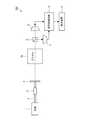
本実施形態に係る磁気計測装置の構成について、図1を参照して説明する。図1は、本実施形態に係る磁気計測装置の構成を示すブロック図である。本実施形態に係る磁気計測装置100は、非線形光学回転(Nonlinear Magneto-Optical Rotation:NMOR)を用いた磁気計測装置である。磁気計測装置100は、例えば、心臓からの磁場(心磁)や脳からの磁場(脳磁)などの生体から発生される微小な磁場を測定する生体状態測定装置(心磁計または脳磁計など)に用いられる。磁気計測装置100は、金属探知機などにも用いることができる。<Configuration of magnetic measuring device>
The configuration of the magnetic measurement apparatus according to the present embodiment will be described with reference to FIG. FIG. 1 is a block diagram showing the configuration of the magnetic measurement apparatus according to this embodiment. The
図1に示すように、磁気計測装置100は、光源1と、光ファイバー2と、コネクター3と、偏光板4と、ガスセル10と、偏光分離器5と、光検出器(Photo Detector:PD)6と、光検出器7と、信号処理回路8と、表示装置9とを備えている。ガスセル10内には、アルカリ金属ガス(気体の状態のアルカリ金属原子)が封入されている。アルカリ金属としては、例えば、セシウム(Cs)、ルビジウム(Rb)、カリウム(K)、ナトリウム(Na)などを用いることができる。以下では、アルカリ金属としてセシウムを用いる場合を例に取り説明する。 As shown in FIG. 1, the
光源1は、セシウムの吸収線に応じた波長(例えばD1線に相当する894nm)のレーザービームを出力する装置、例えばチューナブルレーザーである。光源1から出力されるレーザービームは、連続的に一定の光量を有する、いわゆるCW(Continuous Wave)光である。 The light source 1 is a device that outputs a laser beam having a wavelength corresponding to the absorption line of cesium (for example, 894 nm corresponding to the D1 line), for example, a tunable laser. The laser beam output from the light source 1 is so-called CW (Continuous Wave) light having a constant light amount continuously.
偏光板4は、レーザービームを特定方向に偏光させ、直線偏光にする素子である。光ファイバー2は、光源1により出力されたレーザービームを、ガスセル10側に導く部材である。光ファイバー2には、例えば、基本モードのみを伝播するシングルモードの光ファイバーが用いられる。コネクター3は、光ファイバー2を偏光板4に接続するための部材である。コネクター3は、ねじ込み式で、光ファイバー2を偏光板4に接続する。 The
ガスセル10は、内部に空隙を有する箱(セル)であり、この空隙(図2(a)に示す主室14)にはアルカリ金属の蒸気(図2(a)に示すアルカリ金属ガス13)が封入されている。ガスセル10の構成については、後述する。 The
偏光分離器5は、入射したレーザービームを、互いに直交する2つの偏光成分のビームに分離する素子である。偏光分離器5は、例えば、ウォラストンプリズムまたは偏光ビームスプリッターである。光検出器6および光検出器7は、レーザービームの波長に感度を有する検出器であり、入射光の光量に応じた電流を信号処理回路8に出力する。光検出器6および光検出器7は、それ自体が磁場を発生すると測定に影響を与える可能性があるので、非磁性の材料で構成されることが望ましい。光検出器6および光検出器7は、ガスセル10からみて偏光分離器5と同じ側(下流側)に配置される。 The polarization separator 5 is an element that separates an incident laser beam into beams of two polarization components orthogonal to each other. The polarization separator 5 is, for example, a Wollaston prism or a polarization beam splitter. The photodetector 6 and the photodetector 7 are detectors sensitive to the wavelength of the laser beam, and output a current corresponding to the amount of incident light to the signal processing circuit 8. It is desirable that the photodetector 6 and the photodetector 7 are made of a non-magnetic material because they themselves may affect the measurement when a magnetic field is generated. The photodetector 6 and the photodetector 7 are disposed on the same side (downstream side) as the polarization separator 5 as viewed from the
磁気計測装置100における各部の配置を、レーザービームの経路に沿って説明すると、レーザービームの経路の最上流には光源1が位置し、以下、上流側から、光ファイバー2、コネクター3、偏光板4、ガスセル10、偏光分離器5、および光検出器6,7の順で配置されている。 The arrangement of each part in the
磁気計測装置100における各部の動作を、レーザービームの進行に沿って説明する。光源1から出力されたレーザービームは、光ファイバー2に導かれて偏光板4に到達する。偏光板4に到達したレーザービームは、偏光度がより高い直線偏光になる。ガスセル10を透過しているレーザービームは、ガスセル10に封入されているアルカリ金属原子を励起(光ポンピング)する。このとき、レーザービームは、磁場の強さに応じた偏光面回転作用を受けて偏光面が回転する。ガスセル10を透過したレーザービームは偏光分離器5により2つの偏光成分のビームに分離される。2つの偏光成分のビームの光量は、光検出器6および光検出器7で計測(プロービング)される。 The operation of each part in the
信号処理回路8は、光検出器6および光検出器7により計測されたビームの光量を示す信号をそれぞれから受け取る。信号処理回路8は、受け取った各信号に基づいて、レーザービームの偏光面の回転角を計測する。偏光面の回転角は、レーザービームの伝播方向の磁場の強さに基づく関数で表される(例えば、D.バドカー、外5名,「原子の共鳴非線形磁気光学回転効果」,レビュー・オブ・モダン・フィジクス誌,米国,米国物理学会,2002年10月,第74巻,第4号,p.1153−1201の数式(2)を参照。数式(2)は線形光学回転に関するものであるが、NMORの場合もほぼ同様の式を用いることができる)。信号処理回路8は、偏光面の回転角からレーザービームの伝播方向における磁場の強さを測定する。表示装置9は、信号処理回路8により測定された磁場の強さを表示する。 The signal processing circuit 8 receives from each of the signals indicating the light amounts of the beams measured by the photodetector 6 and the photodetector 7. The signal processing circuit 8 measures the rotation angle of the polarization plane of the laser beam based on each received signal. The rotation angle of the polarization plane is expressed as a function based on the strength of the magnetic field in the propagation direction of the laser beam (for example, D. Budker, et al., “Resonant nonlinear magneto-optical rotation effect of atoms”, Review of See Formula (2) in Modern Physics, USA, American Physical Society, October 2002, Vol. 74, No. 4, pp. 1153-1120. In the case of NMOR, almost the same formula can be used). The signal processing circuit 8 measures the strength of the magnetic field in the propagation direction of the laser beam from the rotation angle of the polarization plane. The
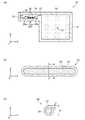
続いて、本実施形態に係るガスセルとガスセルに用いられるアンプルとについて、図2を参照して説明する。図2は、本実施形態に係るガスセルおよびアンプルの構成を示す概略断面図である。詳しくは、図2(a)はガスセルの概略断面図であり、図2(b)はアンプルの概略断面図であり、図2(c)は図2(b)のA−A’線に沿った概略断面図である。 Next, the gas cell according to the present embodiment and the ampule used for the gas cell will be described with reference to FIG. FIG. 2 is a schematic cross-sectional view showing the configuration of the gas cell and the ampoule according to the present embodiment. Specifically, FIG. 2A is a schematic cross-sectional view of a gas cell, FIG. 2B is a schematic cross-sectional view of an ampule, and FIG. 2C is along the line AA ′ in FIG. FIG.
<ガスセルの構成>
図2(a)に、本実施形態に係るガスセル10の概略断面を示す。図2(a)において、ガスセル10の高さ方向をZ軸とし、上方70側を+Z方向とする。Z軸と交差する方向であって、ガスセル10の長さ方向をX軸とし、図2(a)における右側を+X方向とする。そして、Z軸およびX軸と交差する方向であって、ガスセル10の幅方向をY軸とし、図2(a)の紙面における手前から奥へ向う側を+Y方向とする。<Configuration of gas cell>
FIG. 2A shows a schematic cross section of the
図2(a)に示すように、本実施形態に係るガスセル10は、セル部12と封止部19とで構成される。セル部12は、内部に空隙を有する箱(セル)であり、第1ガラスとしての石英ガラスにより形成されている。セル部12の内壁は、例えばパラフィンなどによりコーティングされていてもよい。セル部12の厚さは、1mm〜5mmであり、例えば、1.5mm程度である。 As shown in FIG. 2A, the
セル部12は、内部の空隙として、第1室としての主室14と、第2室としてのリザーバー16とを有している。主室14とリザーバー16とは、X方向に沿って並ぶように配置されており、連通孔15を介して連通している。連通孔15は、主室14およびリザーバー16の上方(+Z方向)側に設けられている。連通孔15の内径は、例えば、0.4mm〜1mm程度である。 The
セル部12のリザーバー16側の端部には、開口部18が設けられている。開口部18は封止部19により封止されており、これにより、セル部12(主室14およびリザーバー16)が密封されている。封止部19の材料としては、例えば、低融点ガラスフリットが用いられる。 An
主室14とリザーバー16とには、アルカリ金属が蒸発したガス(以下ではアルカリ金属ガスという)13が充填されている。主室14とリザーバー16とには、アルカリ金属ガス13の他に、希ガス等の不活性ガスが存在していてもよい。リザーバー16には、ガラス片22aと、アルカリ金属の固体(以下ではアルカリ金属固体という)24と、アルカリ金属が溶融した液体(以下ではアルカリ金属液体という)24aとが配置されている。ガラス片22aには、アルカリ金属固体24とアルカリ金属液体24aとが付着している。 The
ガラス片22aは、後述するアンプル20(図2(b)参照)のガラス管22が破壊されて複数の破片に分断されたものである。アルカリ金属固体24は、破壊される前のアンプル20に封入されており、アンプル20が破壊されたことにより放出されたものである。アルカリ金属液体24aは、アルカリ金属固体24が熱により溶融したものである。アルカリ金属ガス13は、アルカリ金属固体24およびアルカリ金属液体24aが蒸発したものである。 The
なお、リザーバー16にはアルカリ金属固体24またはアルカリ金属液体24aのいずれか一方のみが配置されていてもよいし、ガラス片22aにはアルカリ金属固体24またはアルカリ金属液体24aのいずれか一方のみが付着していてもよい。 Only one of the alkali metal solid 24 and the
<アンプルの構成>
図2(b)にアンプル20のX−Z断面を示す。図2(b)に示すように、本実施形態に係るアンプル20は、中空状のガラス管22で構成される。ガラス管22は、第2ガラスとしてのホウ珪酸ガラスにより形成されている。<Configuration of ampoule>
FIG. 2B shows an XZ cross section of the
ガラス管22は、一方向(図2(b)ではX軸)に沿って延在しており、その両端部が溶着されている。これにより、内部が中空状のガラス管22は密封されている。なお、ガラス管22の両端部の形状は、図2(b)に示すような丸い形状に限定されず、平面に近い形状や一部が尖った形状などであってもよい。ガラス管22の中空部には、アルカリ金属固体(粒状や粉末状のアルカリ金属原子)24が充填されている。アルカリ金属固体24としては、上述したように、セシウムの他に、ルビジウム、カリウム、ナトリウムを用いることができる。 The
図2(b)には、アンプル20(ガラス管22)が密封された状態、すなわち、破壊される前の状態を示している。アンプル20が製造された段階ではガラス管22は密封された状態であるが、図2(a)に示すガスセル10が完成した段階では、ガラス管22は破壊されている。そして、リザーバー16にアンプル20内から放出されたアルカリ金属固体24およびアルカリ金属液体24aが配置されており、リザーバー16と主室14とがアルカリ金属ガス13で満たされている。 FIG. 2B shows a state where the ampoule 20 (glass tube 22) is sealed, that is, a state before being broken. At the stage where the
なお、リザーバー16内でアルカリ金属固体24およびアルカリ金属液体24aが蒸発しアルカリ金属ガス13が連通孔15を介して主室14へ流出し易くなるように、アンプル20の上面とセル部12の内面との間には、例えば1.5mm程度の隙間が設けられている。 Note that the upper surface of the
図2(c)に、アンプル20のY−Z断面を示す。図2(c)に示すように、ガラス管22のY−Z断面形状は、例えば略円形であるが、他の形状であってもよい。ガラス管22の外径φは、0.2mm≦φ≦1.2mmである。ガラス管22の肉厚tは、0.1mm≦t≦0.5mmであり、概ね外径φの20%程度であることが好ましい。ガラス管22の肉厚tが0.1mm未満であるとガラス管22が不用意に破損し易くなり、ガラス管22の肉厚tが0.5mmを超えると、ガラス管22を破壊する加工(詳細は後述する)が困難となる。 FIG. 2C shows a YZ cross section of the
<ガスセルの製造方法>
ガスセル10の製造方法を図3を参照して説明する。図3は、本実施形態に係るガスセルの製造方法を説明する図である。<Gas cell manufacturing method>
A method for manufacturing the
まず、図3(a)に示すセル部12を用意する。図示を省略するが、例えば、石英ガラスからなるガラス板を切断して、セル部12を構成する各壁面に対応するガラス板部材を準備する。そして、これらのガラス板部材を組立て、ガラス板部材同士を接着剤または溶着により接合して、図3(a)に示すような主室14とリザーバー16とを有するセル部12を得る。この段階では、セル部12の開口部18は開放されている。 First, the
続いて、セル部12のリザーバー16内にアンプル20を収納する。アンプル20は、セル部12のリザーバー16側に設けられた開口部18から挿入され、リザーバー16内に収納される。この段階では、アンプル20は、図2(b)に示すように、中空状のガラス管22の内部にアルカリ金属固体24が充填され密封された状態となっている。 Subsequently, the
なお、アンプル20は、真空に近い低圧環境下(理想的には真空中)において、管状のガラス管22の中空部にアルカリ金属固体24を充填し、ガラス管22の両端部をそれぞれ溶着し密封して形成する。アルカリ金属固体24として用いられるセシウムなどのアルカリ金属は、反応性に富み大気中で取り扱うことができないため、低圧環境下でアンプル20内に密封された状態でセル部12に収納される。 The
続いて、図3(a)に示すセル部12内の脱気を十分に行い、内部の空隙に不純物が極めて少ない状態で、図3(b)に示すように、セル部12(主室14、連通孔15、およびリザーバー16)を封止する。例えば、真空に近い低圧環境下(理想的には真空中)において、セル部12の開口部18を封止部19で封止することにより、セル部12を密封する。 Subsequently, the inside of the
続いて、図3(c)に示すように、アンプル20(ガラス管22)を加工する。この工程では、セル部12に損傷を与えることなくガラス管22を破壊して、アンプル20の気密を破るとともに、アンプル20内のアルカリ金属固体24をリザーバー16へ放出させる。ガラス管22の破壊とは、ガラス管22を貫通する貫通孔を形成することや、ガラス管22を複数のガラス片22aに分断することを指す。 Subsequently, as shown in FIG. 3C, the ampoule 20 (glass tube 22) is processed. In this step, the
例えば、ガラス管22に貫通孔を形成する場合、形成された貫通孔からアンプル20内のアルカリ金属固体24をリザーバー16へ放出させる必要がある。したがって、貫通孔の径は10μm〜50μm程度でもよいがより大きい(例えば100μm以上)方が好ましく、貫通孔の数は一つでもよいが複数形成する方が好ましい。また、アルカリ金属固体24を確実に放出させる観点からは、図3(c)に示すように、ガラス管22を複数のガラス片22aに分断することがより好ましい。 For example, when a through hole is formed in the
本実施形態では、ガラス管22を破壊する方法として、レーザー光としてのパルスレーザー光40を、集光レンズ42で集光して、上方(+Z方向)側からセル部12を間に介してアンプル20のガラス管22に照射する。レーザー光は指向性や収束性に優れているので、ガラス管22を容易に加工することができる。 In the present embodiment, as a method of breaking the
なお、集光レンズ42として、例えば焦点距離が78mmのレンズを用いると、集光したパルスレーザー光40のビームスポット径は10μm程度となる。アンプル20の上面とセル部12の内面との間に1.5mm程度の隙間が設けられているので、パルスレーザー光40の焦点をガラス管22の上面に合わせることで、セル部12に損傷を与えるリスクを小さくできる。 For example, when a lens having a focal length of 78 mm is used as the
また、本実施形態では、パルスレーザー光40として、紫外線領域の波長帯域である248nm〜355nmのパルスレーザー光を用いる。図4は、光の波長とガラス材料の透過率との関係を比較して示す図である。図4に示すように、石英ガラスの透過率は、光の波長が250nm〜400nmの範囲において95%程度であり、ほとんど変化しない。 In the present embodiment, a pulse laser beam having a wavelength band of 248 nm to 355 nm, which is a wavelength band in the ultraviolet region, is used as the
一方、図4に示すホウ珪酸ガラスの透過率は、光の波長が270nmまでは0%程度であるが、270nm〜350nmの範囲において増加し、350nm以上では90%程度となる。なお、図4に示す透過率は一例を示したものであり、例えば、ホウ珪酸ガラスの透過率は、ホウ珪酸ガラスを構成する成分の混合比により図4に示す例とは異なる場合がある。 On the other hand, the transmittance of the borosilicate glass shown in FIG. 4 is about 0% until the light wavelength is 270 nm, but increases in the range of 270 nm to 350 nm, and is about 90% at 350 nm or more. In addition, the transmittance | permeability shown in FIG. 4 shows an example, for example, the transmittance | permeability of borosilicate glass may differ from the example shown in FIG. 4 with the mixing ratio of the component which comprises borosilicate glass.
このように、紫外線領域の波長帯域の光(以下では、紫外光という)に対して、石英ガラスの透過率はホウ珪酸ガラスの透過率よりも高い。換言すれば、紫外光に対して、石英ガラスの吸収係数はホウ珪酸ガラスの吸収係数よりも小さい。したがって、紫外光であるパルスレーザー光40は、石英ガラスからなるセル部12を透過し、ホウ珪酸ガラスからなるガラス管22に吸収される。これにより、セル部12に損傷を与えることなく、ガラス管22を選択的に加工することができる。 Thus, the transmittance of quartz glass is higher than the transmittance of borosilicate glass for light in the wavelength band of the ultraviolet region (hereinafter referred to as ultraviolet light). In other words, for ultraviolet light, the absorption coefficient of quartz glass is smaller than that of borosilicate glass. Therefore, the
本実施形態では、パルスレーザー光40として、YAGレーザーの第3高調波(THG)レーザーを用いるが、第4高調波(FHG)レーザーを用いることもできる。パルスレーザー光40は、例えば、エネルギーを50μJ/pulse〜200μJ/pulse程度とし、パルス幅をナノ秒オーダー(好ましくは30ナノ秒程度)とし、繰り返し周波数を50kHzとし、照射時間を100msecとする。 In the present embodiment, a third harmonic (THG) laser of a YAG laser is used as the
パルスレーザー光40を照射することにより、ガラス管22が上面(表面)から深さ方向に加工されて破壊され、アンプル20の密封が破られる。ここで、パルスレーザー光40のエネルギーが高いと、ガラス管22自体が発熱するだけでなくアルカリ金属固体24も発熱する。このような発熱によりガラス管22に生じる熱応力を利用すれば、ガラス管22を破壊し易くなる。また、アルカリ金属固体24が発熱すると蒸発し易くなり、アルカリ金属の融点以上の温度になると溶融してアルカリ金属液体24aとなる。アルカリ金属固体24がセシウムである場合、セシウムの融点は28.4℃程度である。 By irradiating the
上述の加工の結果、図2(a)に示すように、ガラス管22が破壊されることにより複数のガラス片22aに分断され、アンプル20内からアルカリ金属固体24がリザーバー16に放出される。図2(a)では、アルカリ金属固体24とともに、アルカリ金属固体24が溶融したアルカリ金属液体24aもリザーバー16内に配置された状態を示している。また、複数のガラス片22aには、アルカリ金属固体24とアルカリ金属液体24aとが付着している。なお、リザーバー16内に配置され複数のガラス片22aに付着するのは、アルカリ金属固体24またはアルカリ金属液体24aのいずれか一方のみであってもよい。 As a result of the above-described processing, as shown in FIG. 2A, the
このように、リザーバー16内にアルカリ金属固体24およびアルカリ金属液体24aの少なくとも一方が配置されると、アルカリ金属が蒸発してアルカリ金属ガス13となり、リザーバー16内がアルカリ金属ガス13で満たされる。そして、アルカリ金属ガス13は、リザーバー16から連通孔15を介して主室14に拡散する。その結果、リザーバー16と主室14とにアルカリ金属ガス13が充填される。 As described above, when at least one of the alkali metal solid 24 and the
このとき、本実施形態では、連通孔15がリザーバー16の上方(+Z方向)側に設けられており、連通孔15の内径が0.4mm〜1mm程度と小さく設定されているので、ガラス片22aおよびアルカリ金属固体24やアルカリ金属液体24aが連通孔15を通って主室14に侵入しにくくなっている。したがって、アルカリ金属ガス13はリザーバー16から主室14に流入するが、ガラス片22aおよびアルカリ金属固体24やアルカリ金属液体24aの主室14への侵入は抑止される。 At this time, in this embodiment, the
なお、ガラス片22a、アルカリ金属固体24、アルカリ金属液体24aなどアルカリ金属ガス13以外のものが主室14に侵入してしまった場合は、磁気計測装置100において光源1から出力されたレーザービームを直線偏光にしてガスセル10(主室14)を透過させる際の透過量が低下するため、磁気計測装置100の性能低下を招く。 In addition, when something other than the
以上で、本実施形態に係るガスセル10を製造できる。本実施形態に係る磁気計測装置の製造方法は、上述したガスセルの製造方法を含んでいる。なお、本実施形態に係る磁気計測装置100を製造する工程は、ガスセル10を製造する工程以外の工程では公知の方法を用いることができるため、その説明を省略する。 With the above, the
ところで、上述したアンプル20を加工する工程において、ガラス管22を破壊する際に不要なガスが発生する場合があり、特に、発熱によりガラス管22が溶解するとガラス管22から不要なガスが発生する。不要なガスとしては、例えば、ガラス管22(ホウ珪酸ガラス)内に含まれる水分などが挙げられる。不要なガスは、セル部12(石英ガラス)からも僅かながら発生され得る。 By the way, in the process of processing the
このような不要なガスがリザーバー16内や主室14内で発生すると、不要なガスがアルカリ金属ガス13と反応し反応した分だけアルカリ金属ガス13が減少するため、主室14に充填されるアルカリ金属ガス13の濃度が低下したりばらついたりしてしまう。主室14においてアルカリ金属ガス13の濃度の低下やばらつきがあると、磁気計測装置100の性能低下を招くこととなる。 When such an unnecessary gas is generated in the
そこで、アンプル20を加工する工程では、ガラス管22を破壊した後ある程度の時間放置し、加工の際にガラス管22(ホウ珪酸ガラス)やセル部12(石英ガラス)から発生した不要なガスとアルカリ金属ガス13とを反応させた上で、アルカリ金属ガス13をリザーバー16と主室14とに充填する。 Therefore, in the step of processing the
仮に、ガラス管22に貫通孔を形成したがアルカリ金属固体24がアンプル20内からリザーバー16へ放出されていない場合、アルカリ金属ガス13は、アンプル20内のアルカリ金属固体24が蒸発することでのみ発生し、アンプル20内から貫通孔を介してリザーバー16へ流出する。そのため、アンプル20内から流出するアルカリ金属ガス13の量が不要なガスに対して相対的に少ないと、アルカリ金属ガス13と反応できない不要なガスがリザーバー16から主室14へ拡散し、リザーバー16内および主室14内で不要なガスがアルカリ金属ガス13と反応し終えるまでに要する時間が長くなる。その結果、主室14におけるアルカリ金属ガス13の濃度の低下やばらつきが生じてしまうおそれがある。 If a through-hole is formed in the
これに対して、本実施形態では、アルカリ金属固体24およびアルカリ金属液体24aの少なくとも一方がリザーバー16内に配置されているため、より多くのアルカリ金属ガス13が安定的に供給されるので、リザーバー16内のアルカリ金属ガス13の量が不要なガスに対して相対的に多くなる。そして、アルカリ金属ガス13だけでなくアルカリ金属固体24やアルカリ金属液体24aも不要なガスとの反応に寄与するので、リザーバー16内の不要なガスをより速く低減できる。さらに、ガラス片22aにアルカリ金属固体24およびアルカリ金属液体24aの少なくとも一方が付着しているため、付着した部分の表面がアルカリ金属固体24またはアルカリ金属液体24aで覆われるので、ガラス片22aからの不要なガスの新たな発生が抑えられる。 On the other hand, in this embodiment, since at least one of the alkali metal solid 24 and the
そのため、リザーバー16から主室14への不要なガスの拡散が抑えられ、かつ、リザーバー16から主室14へ流入するアルカリ金属ガス13の量をより多くできる。そして、主室14において不要なガスが発生した場合でも、リザーバー16から流入するアルカリ金属ガス13と反応させることができる。これにより、リザーバー16および主室14において、不要なガスとアルカリ金属ガス13との反応をより速く終わらせ、アルカリ金属ガス13の濃度を安定させることができる。この結果、ガスセル10の主室14におけるアルカリ金属ガス13の濃度の低下やばらつきが抑えられるので、生体から発生される磁場を高精度で計測することが可能なガスセル10および磁気計測装置100を安定的に製造することができる。 Therefore, unnecessary gas diffusion from the
上述した実施形態は、あくまでも本発明の一態様を示すものであり、本発明の範囲内で任意に変形および応用が可能である。変形例としては、例えば、以下のようなものが考えられる。 The above-described embodiments merely show one aspect of the present invention, and can be arbitrarily modified and applied within the scope of the present invention. As modifications, for example, the following can be considered.
(変形例1)
上記実施形態の製造方法では、アンプル20のガラス管22を破壊する方法としてパルスレーザー光40を照射したが、本発明はこのような構成に限定されない。アンプル20のガラス管22を破壊する方法として、例えば、アンプル20に衝撃を加える方法を用いてもよい。図5は、変形例1に係るガスセルの製造方法を説明する図である。(Modification 1)
In the manufacturing method of the above embodiment, the
図3(b)に示すようにセル部12を密封した後、図5(a)に示すようにセル部12に振動または衝撃を加える。外径φが0.2mm≦φ≦1.2mmのアンプル20に対して、アンプル20の上面とリザーバー16の内面との間に1.5mm程度の隙間が設けられているため、セル部12に振動または衝撃を加えると、アンプル20はリザーバー16内で容易に移動する。そのため、アンプル20がリザーバー16の内面と衝突し、その衝突の衝撃によりアンプル20のガラス管22が破壊される。これにより、図5(b)に示すように、アンプル20(ガラス管22)を複数のガラス片22aに分断することができる。なお、図5(a)にはZ方向に沿って振動または衝撃を加える場合を示しているが、セル部12に振動または衝撃を加える方向はY方向に沿った方向であってもよい。 After sealing the
変形例1のように衝撃を加えてアンプル20を破壊する方法では、上記実施形態のパルスレーザー光40を照射する方法と比べて、発熱に伴う不要なガスの発生を抑えることができる。図5(b)には、発熱が抑えられたことによりアルカリ金属固体24が溶融せず、リザーバー16にアルカリ金属液体24a(図2(a)参照)が配置されなかった場合の例を示している。一方、変形例1のように衝撃を加えてアンプル20を破壊する方法では、衝撃によりガラス片22aやアルカリ金属固体24がリザーバー16内で移動するため、ガラス片22aやアルカリ金属固体24が連通孔15を通って主室14に侵入するリスクは大きくなる。 Compared with the method of irradiating the
(変形例2)
上記実施形態に係るガスセル10を適用可能な装置は、磁気計測装置100に限定されない。ガスセル10は、例えば、原子時計などの原子発振器にも適用できる。原子発振器に用いられるガスセルには小型化が要求されるが、上記実施形態のガスセルの製造方法によれば、小型のガスセル10を安定的に製造できるので、小型の原子発振器に好適に用いることができる。(Modification 2)
An apparatus to which the
10…ガスセル、12…セル部(第1ガラス)、13…アルカリ金属ガス(アルカリ金属のガス)、14…主室(第1室)、15…連通孔、16…リザーバー(第2室)、20…アンプル、22…ガラス管(第2ガラス)、22a…ガラス片、24…アルカリ金属固体(アルカリ金属の固体)、24a…アルカリ金属液体(アルカリ金属の液体)、40…パルスレーザー光(レーザー光)、100…磁気計測装置。 DESCRIPTION OF
Claims (11)
Translated fromJapanese第1室と、第2室と、前記第1室と前記第2室とを連通する連通孔と、を備えたガスセルを含み、
前記第1室と前記第2室とにはアルカリ金属のガスが充填され、
前記第2室には、前記アルカリ金属の固体および液体の少なくとも一方が配置されていることを特徴とする磁気計測装置。A magnetic measurement device for measuring a magnetic field,
Including a gas cell comprising a first chamber, a second chamber, and a communication hole communicating the first chamber and the second chamber;
The first chamber and the second chamber are filled with an alkali metal gas,
In the second chamber, at least one of the alkali metal solid and the liquid is disposed.
前記第2室には、ガラス片が配置され、
前記ガラス片には、前記アルカリ金属の固体および液体の少なくとも一方が付着していることを特徴とする磁気計測装置。The magnetic measurement device according to claim 1,
A glass piece is disposed in the second chamber,
At least one of the alkali metal solid and the liquid adheres to the glass piece.
前記第1室と前記第2室とは第1ガラスで構成され、
前記ガラス片は、前記第1ガラスとは異なる第2ガラスで構成されることを特徴とする磁気計測装置。The magnetic measurement device according to claim 2,
The first chamber and the second chamber are composed of a first glass,
The said glass piece is comprised with 2nd glass different from the said 1st glass, The magnetic measuring device characterized by the above-mentioned.
前記第1ガラスの厚さは1mm〜5mmであり、前記第2ガラスの厚さは0.1mm〜0.5mmであることを特徴とする磁気計測装置。The magnetic measurement device according to claim 3,
The thickness of the first glass is 1 mm to 5 mm, and the thickness of the second glass is 0.1 mm to 0.5 mm.
前記第1ガラスにおける紫外光の透過率は、前記第2ガラスにおける紫外光の透過率よりも高いことを特徴とする磁気計測装置。The magnetic measurement device according to claim 3 or 4,
The magnetic measurement apparatus according to claim 1, wherein the transmittance of ultraviolet light in the first glass is higher than the transmittance of ultraviolet light in the second glass.
前記連通孔の径は、0.4mm〜1mmであることを特徴とする磁気計測装置。A magnetic measuring device according to any one of claims 1 to 5,
The diameter of the said communicating hole is 0.4 mm-1 mm, The magnetic measuring device characterized by the above-mentioned.
前記第1室と前記第2室とにはアルカリ金属のガスが充填され、
前記第2室には、前記アルカリ金属の固体および液体の少なくとも一方が配置されていることを特徴とするガスセル。A first chamber, a second chamber, and a communication hole communicating the first chamber and the second chamber;
The first chamber and the second chamber are filled with an alkali metal gas,
In the second chamber, at least one of the alkali metal solid and the liquid is disposed.
第1室と、第2室と、前記第1室と前記第2室とを連通する連通孔と、を備えたガスセルの前記第2室に、アルカリ金属の固体が封入されたアンプルを配置し、前記第1室と前記第2室と前記連通孔とを密封する工程と、
前記アンプルを破壊して、前記第2室に前記アルカリ金属の固体および液体の少なくとも一方を配置する工程と、
前記第1室と前記第2室とに、前記アルカリ金属のガスを充填する工程と、
を含むことを特徴とする磁気計測装置の製造方法。A method of manufacturing a magnetic measuring device for measuring a magnetic field,
An ampoule filled with an alkali metal solid is disposed in the second chamber of the gas cell having a first chamber, a second chamber, and a communication hole that communicates the first chamber and the second chamber. Sealing the first chamber, the second chamber, and the communication hole;
Breaking the ampoule and placing at least one of the alkali metal solid and liquid in the second chamber;
Filling the first chamber and the second chamber with the alkali metal gas;
The manufacturing method of the magnetic measuring device characterized by including this.
前記アンプルにレーザー光を照射することにより前記アンプルを破壊することを特徴とする磁気計測装置の製造方法。It is a manufacturing method of the magnetic measuring device according to claim 8,
A method of manufacturing a magnetic measuring device, wherein the ampoule is destroyed by irradiating the ampoule with laser light.
前記アンプルに衝撃を加えることにより前記アンプルを破壊することを特徴とする磁気計測装置の製造方法。It is a manufacturing method of the magnetic measuring device according to claim 8,
A method of manufacturing a magnetic measuring device, wherein the ampoule is destroyed by applying an impact to the ampoule.
前記アンプルを破壊して、前記第2室に前記アルカリ金属の固体および液体の少なくとも一方を配置する工程と、
前記第1室と前記第2室とに、前記アルカリ金属のガスを充填する工程と、
を含むことを特徴とするガスセルの製造方法。Disposing an ampoule filled with an alkali metal solid in a second chamber communicating with the first chamber via a communication hole, and sealing the first chamber, the communication hole, and the second chamber;
Breaking the ampoule and placing at least one of the alkali metal solid and liquid in the second chamber;
Filling the first chamber and the second chamber with the alkali metal gas;
A method for producing a gas cell, comprising:
Priority Applications (3)
| Application Number | Priority Date | Filing Date | Title |
|---|---|---|---|
| JP2014214254AJP2016080613A (en) | 2014-10-21 | 2014-10-21 | Magnetic measuring device, gas cell, manufacturing method of magnetic measuring device, and manufacturing method of gas cell |
| US14/886,808US10107876B2 (en) | 2014-10-21 | 2015-10-19 | Magnetism measurement apparatus, gas cell, method for manufacturing magnetism measurement apparatus, and method for manufacturing gas cell |
| CN201510683363.4ACN105527591A (en) | 2014-10-21 | 2015-10-20 | Magnetism measurement apparatus, gas cell, method for manufacturing magnetism measurement apparatus, and method for manufacturing gas cell |
Applications Claiming Priority (1)
| Application Number | Priority Date | Filing Date | Title |
|---|---|---|---|
| JP2014214254AJP2016080613A (en) | 2014-10-21 | 2014-10-21 | Magnetic measuring device, gas cell, manufacturing method of magnetic measuring device, and manufacturing method of gas cell |
Publications (2)
| Publication Number | Publication Date |
|---|---|
| JP2016080613Atrue JP2016080613A (en) | 2016-05-16 |
| JP2016080613A5 JP2016080613A5 (en) | 2017-10-26 |
Family
ID=55748888
Family Applications (1)
| Application Number | Title | Priority Date | Filing Date |
|---|---|---|---|
| JP2014214254AWithdrawnJP2016080613A (en) | 2014-10-21 | 2014-10-21 | Magnetic measuring device, gas cell, manufacturing method of magnetic measuring device, and manufacturing method of gas cell |
Country Status (3)
| Country | Link |
|---|---|
| US (1) | US10107876B2 (en) |
| JP (1) | JP2016080613A (en) |
| CN (1) | CN105527591A (en) |
Families Citing this family (7)
| Publication number | Priority date | Publication date | Assignee | Title |
|---|---|---|---|---|
| JP2016080613A (en)* | 2014-10-21 | 2016-05-16 | セイコーエプソン株式会社 | Magnetic measuring device, gas cell, manufacturing method of magnetic measuring device, and manufacturing method of gas cell |
| US10145909B2 (en)* | 2014-11-17 | 2018-12-04 | Seiko Epson Corporation | Magnetism measuring device, gas cell, manufacturing method of magnetism measuring device, and manufacturing method of gas cell |
| JP7188965B2 (en)* | 2018-10-05 | 2022-12-13 | 浜松ホトニクス株式会社 | Cell module for photoexcited magnetic sensor |
| CN111289924B (en)* | 2018-12-10 | 2025-06-17 | 中科知影(北京)科技有限公司 | Multi-channel atomic magnetic detector |
| CN111024258B (en)* | 2019-12-18 | 2021-03-23 | 北京航空航天大学 | An Alkali Metal Gas Chamber Internal Heat Distribution and Thermal Stability Measuring Device |
| CN114019215A (en)* | 2021-10-26 | 2022-02-08 | 上海电铠智能科技有限公司 | Current sensor based on atomic spin regulation vector light field |
| CN115684327B (en)* | 2022-11-07 | 2024-05-03 | 北京自动化控制设备研究所 | Method and system for testing gas components in atomic gas chamber |
Citations (11)
| Publication number | Priority date | Publication date | Assignee | Title |
|---|---|---|---|---|
| JPS4819508B1 (en)* | 1969-07-22 | 1973-06-14 | ||
| JPS54118674A (en)* | 1978-03-08 | 1979-09-14 | Toshiba Corp | Low pressure mercury vapor discharge lamp |
| JPH09185944A (en)* | 1995-10-30 | 1997-07-15 | Philips Electron Nv | Manufacture of low pressure mercury discharge lamp and low pressure mercury discharge lamp |
| JPH10263873A (en)* | 1997-03-27 | 1998-10-06 | Sumitomo Heavy Ind Ltd | Laser beam machine and machining method |
| JPH11238469A (en)* | 1998-02-24 | 1999-08-31 | Dainippon Printing Co Ltd | Plasma display panel, manufacturing method thereof, and gas capsule |
| US6055829A (en)* | 1997-07-07 | 2000-05-02 | Schott Glas | Process for producing a desired breaking point on a glass body |
| US20110006252A1 (en)* | 2009-07-10 | 2011-01-13 | Beijing Synergy Vacuum Glazing Technology Co., Ltd. | Encapsulated getter arranged in vacuum glazing |
| JP2012183290A (en)* | 2011-02-16 | 2012-09-27 | Seiko Epson Corp | Production method of gas cell, and gas cell |
| JP2013065819A (en)* | 2011-08-29 | 2013-04-11 | Seiko Epson Corp | Sealing method of package |
| US20130247615A1 (en)* | 2010-11-30 | 2013-09-26 | Corning Incorporated | Methods of forming high-density arrays of holes in glass |
| WO2014132651A1 (en)* | 2013-02-28 | 2014-09-04 | 国立大学法人京都大学 | Process for producing alkali-metal cell, process for producing alkali metal, and cell containing alkali-metal gas |
Family Cites Families (35)
| Publication number | Priority date | Publication date | Assignee | Title |
|---|---|---|---|---|
| US6917276B1 (en) | 2000-06-19 | 2005-07-12 | Simpler Networks | Bistable switch with shape memory metal |
| CN1152251C (en)* | 2001-05-10 | 2004-06-02 | 中国科学院武汉物理与数学研究所 | Laser Polarized Inert Gas Device |
| US20050052650A1 (en)* | 2003-09-05 | 2005-03-10 | Zhen Wu | System for high-resolution measurement of a magnetic field/gradient and its application to a magnetometer or gradiometer |
| JP5424578B2 (en)* | 2007-06-05 | 2014-02-26 | キヤノン株式会社 | Magnetic sensing method, atomic magnetic sensor, and magnetic resonance imaging apparatus |
| JP5039452B2 (en)* | 2007-06-27 | 2012-10-03 | 株式会社日立ハイテクノロジーズ | Magnetic field measuring device |
| US7826065B1 (en)* | 2008-07-15 | 2010-11-02 | Sandia Corporation | Tuned optical cavity magnetometer |
| JP5365367B2 (en)* | 2009-06-24 | 2013-12-11 | セイコーエプソン株式会社 | Magnetic sensor |
| JP5223794B2 (en)* | 2009-06-26 | 2013-06-26 | セイコーエプソン株式会社 | Magnetic sensor |
| JP5446731B2 (en)* | 2009-10-29 | 2014-03-19 | セイコーエプソン株式会社 | Magnetic field measuring device |
| JP5699725B2 (en)* | 2011-03-23 | 2015-04-15 | セイコーエプソン株式会社 | Gas cell manufacturing apparatus and gas cell manufacturing method |
| JP5799553B2 (en)* | 2011-04-01 | 2015-10-28 | セイコーエプソン株式会社 | Magnetic field measuring apparatus, magnetic field measuring system, and magnetic field measuring method |
| JP6134092B2 (en)* | 2011-10-18 | 2017-05-24 | セイコーエプソン株式会社 | Magnetic field measuring device |
| JP5816697B2 (en)* | 2011-11-18 | 2015-11-18 | 株式会社日立製作所 | Magnetic field measuring apparatus and manufacturing method thereof |
| JP2013170816A (en)* | 2012-02-17 | 2013-09-02 | Seiko Epson Corp | Gas cell and magnetic field measurement device |
| JP5994293B2 (en) | 2012-03-05 | 2016-09-21 | セイコーエプソン株式会社 | Magnetometer, gas cell, and gas cell manufacturing method |
| JP5972006B2 (en)* | 2012-03-29 | 2016-08-17 | キヤノン株式会社 | Optical pumping magnetometer and magnetic force measuring method |
| JP6171355B2 (en)* | 2013-01-21 | 2017-08-02 | セイコーエプソン株式会社 | Magnetic field measuring device |
| JP6222974B2 (en)* | 2013-04-25 | 2017-11-01 | キヤノン株式会社 | Optical pumping magnetometer and magnetic sensing method |
| WO2015019471A1 (en)* | 2013-08-08 | 2015-02-12 | 株式会社日立製作所 | Magnetic field measuring device |
| CN103438877B (en)* | 2013-09-02 | 2016-03-30 | 北京航空航天大学 | A kind of inertia based on SERF atomic spin effect and magnetic field integral measurement method |
| US10215816B2 (en)* | 2013-12-03 | 2019-02-26 | Hitachi, Ltd. | Magnetic field measuring apparatus |
| JP2015118962A (en)* | 2013-12-16 | 2015-06-25 | セイコーエプソン株式会社 | Quantum interference devices, atomic oscillators, electronic equipment, and moving objects |
| CN103869265B (en)* | 2014-03-26 | 2016-04-27 | 北京大学 | For the nonmagnetic atom sensor of optically pumped magnetometer |
| US9778328B2 (en)* | 2014-05-30 | 2017-10-03 | Northrop Grumman Systems Corporation | Optical probe beam stabilization in an atomic sensor system |
| JP2016008836A (en)* | 2014-06-23 | 2016-01-18 | セイコーエプソン株式会社 | Gas cell |
| JP6488572B2 (en)* | 2014-07-02 | 2019-03-27 | セイコーエプソン株式会社 | Gas cell, gas cell sealing method, and gas cell manufacturing method |
| JP6464593B2 (en)* | 2014-07-24 | 2019-02-06 | セイコーエプソン株式会社 | Gas cell manufacturing method |
| JP2016029362A (en)* | 2014-07-24 | 2016-03-03 | セイコーエプソン株式会社 | Gas cell and magnetic measuring device |
| JP2016070900A (en)* | 2014-10-02 | 2016-05-09 | セイコーエプソン株式会社 | Manufacturing method of magnetic measuring device, manufacturing method of gas cell, magnetic measuring device and gas cell |
| JP2016080613A (en)* | 2014-10-21 | 2016-05-16 | セイコーエプソン株式会社 | Magnetic measuring device, gas cell, manufacturing method of magnetic measuring device, and manufacturing method of gas cell |
| JP6511782B2 (en)* | 2014-11-17 | 2019-05-15 | セイコーエプソン株式会社 | Atomic oscillator and gas cell |
| US10145909B2 (en)* | 2014-11-17 | 2018-12-04 | Seiko Epson Corporation | Magnetism measuring device, gas cell, manufacturing method of magnetism measuring device, and manufacturing method of gas cell |
| JP2016205984A (en)* | 2015-04-22 | 2016-12-08 | セイコーエプソン株式会社 | Magnetic measuring device, magnetic measuring device manufacturing method, gas cell, and gas cell manufacturing method |
| JP2017125689A (en)* | 2016-01-12 | 2017-07-20 | セイコーエプソン株式会社 | Magnetic measuring device, gas cell, manufacturing method of magnetic measuring device, and manufacturing method of gas cell |
| JP2017191040A (en)* | 2016-04-14 | 2017-10-19 | セイコーエプソン株式会社 | Magnetic field measurement device and magnetic field measurement method |
- 2014
- 2014-10-21JPJP2014214254Apatent/JP2016080613A/ennot_activeWithdrawn
- 2015
- 2015-10-19USUS14/886,808patent/US10107876B2/ennot_activeExpired - Fee Related
- 2015-10-20CNCN201510683363.4Apatent/CN105527591A/enactivePending
Patent Citations (11)
| Publication number | Priority date | Publication date | Assignee | Title |
|---|---|---|---|---|
| JPS4819508B1 (en)* | 1969-07-22 | 1973-06-14 | ||
| JPS54118674A (en)* | 1978-03-08 | 1979-09-14 | Toshiba Corp | Low pressure mercury vapor discharge lamp |
| JPH09185944A (en)* | 1995-10-30 | 1997-07-15 | Philips Electron Nv | Manufacture of low pressure mercury discharge lamp and low pressure mercury discharge lamp |
| JPH10263873A (en)* | 1997-03-27 | 1998-10-06 | Sumitomo Heavy Ind Ltd | Laser beam machine and machining method |
| US6055829A (en)* | 1997-07-07 | 2000-05-02 | Schott Glas | Process for producing a desired breaking point on a glass body |
| JPH11238469A (en)* | 1998-02-24 | 1999-08-31 | Dainippon Printing Co Ltd | Plasma display panel, manufacturing method thereof, and gas capsule |
| US20110006252A1 (en)* | 2009-07-10 | 2011-01-13 | Beijing Synergy Vacuum Glazing Technology Co., Ltd. | Encapsulated getter arranged in vacuum glazing |
| US20130247615A1 (en)* | 2010-11-30 | 2013-09-26 | Corning Incorporated | Methods of forming high-density arrays of holes in glass |
| JP2012183290A (en)* | 2011-02-16 | 2012-09-27 | Seiko Epson Corp | Production method of gas cell, and gas cell |
| JP2013065819A (en)* | 2011-08-29 | 2013-04-11 | Seiko Epson Corp | Sealing method of package |
| WO2014132651A1 (en)* | 2013-02-28 | 2014-09-04 | 国立大学法人京都大学 | Process for producing alkali-metal cell, process for producing alkali metal, and cell containing alkali-metal gas |
Also Published As
| Publication number | Publication date |
|---|---|
| US10107876B2 (en) | 2018-10-23 |
| CN105527591A (en) | 2016-04-27 |
| US20160109538A1 (en) | 2016-04-21 |
Similar Documents
| Publication | Publication Date | Title |
|---|---|---|
| JP2016070900A (en) | Manufacturing method of magnetic measuring device, manufacturing method of gas cell, magnetic measuring device and gas cell | |
| JP2016080613A (en) | Magnetic measuring device, gas cell, manufacturing method of magnetic measuring device, and manufacturing method of gas cell | |
| JP2017125689A (en) | Magnetic measuring device, gas cell, manufacturing method of magnetic measuring device, and manufacturing method of gas cell | |
| JP2016205984A (en) | Magnetic measuring device, magnetic measuring device manufacturing method, gas cell, and gas cell manufacturing method | |
| US10145909B2 (en) | Magnetism measuring device, gas cell, manufacturing method of magnetism measuring device, and manufacturing method of gas cell | |
| JP5821439B2 (en) | Gas cell manufacturing method | |
| US10393825B2 (en) | Manufacturing method for gas cell, manufacturing method for magnetic field measurement apparatus, and gas cell | |
| US9497842B2 (en) | System and method for generating extreme ultraviolet light | |
| JP5547440B2 (en) | Physics package for cold atom primary frequency standards | |
| JP2018084452A (en) | Gas cell, magnetic field measurement device, and method for forming gas cell | |
| JP2016207695A (en) | Atomic cell, method for manufacturing atomic cell, quantum interference device, atomic oscillator, electronic apparatus and mobile body | |
| JP2018132348A (en) | Gas cell, magnetic measuring device, and atomic oscillator | |
| JP2017227584A (en) | Method of manufacturing gas cell and method of manufacturing magnetic measuring device | |
| JP2016095262A (en) | Magnetic measuring device, gas cell, manufacturing method of magnetic measuring device, and manufacturing method of gas cell | |
| JP2018163910A (en) | Gas cell manufacturing method, gas cell, magnetic measuring device, and atomic oscillator | |
| US11002808B2 (en) | Gas cell, magnetometric device, method of manufacturing gas cell, and method of manufacturing magnetometric device | |
| JP2016080459A (en) | Magnetic measuring device manufacturing method, gas cell manufacturing method, magnetic measuring device, and gas cell | |
| JP2018146532A (en) | Gas cell manufacturing method, gas cell, magnetic measuring device, and atomic oscillator | |
| JP6503697B2 (en) | Gas cell manufacturing method and atomic oscillator | |
| JP2017125690A (en) | Magnetic measuring device manufacturing method and gas cell manufacturing method | |
| JP2018054404A (en) | GAS CELL, MAGNETIC MEASURING DEVICE, AND GAS CELL MANUFACTURING METHOD | |
| JP2018028550A (en) | GAS CELL MANUFACTURING METHOD, MAGNETIC MEASURING DEVICE MANUFACTURING METHOD, GAS CELL, AND MAGNETIC MEASURING DEVICE | |
| Ziaee et al. | Probing ultrafast molecular dynamics by time-resolved coincident ion momentum imaging | |
| JP2018120977A (en) | Atomic cell, quantum interference device, atomic oscillator, electronic device, and moving object | |
| Dreher | Experimental Demonstration of Superradiant Amplification of Ultra-Short Laser Pulses in a Plasma |
Legal Events
| Date | Code | Title | Description |
|---|---|---|---|
| RD03 | Notification of appointment of power of attorney | Free format text:JAPANESE INTERMEDIATE CODE: A7423 Effective date:20160623 | |
| A521 | Request for written amendment filed | Free format text:JAPANESE INTERMEDIATE CODE: A523 Effective date:20170912 | |
| A621 | Written request for application examination | Free format text:JAPANESE INTERMEDIATE CODE: A621 Effective date:20170912 | |
| A131 | Notification of reasons for refusal | Free format text:JAPANESE INTERMEDIATE CODE: A131 Effective date:20180703 | |
| A977 | Report on retrieval | Free format text:JAPANESE INTERMEDIATE CODE: A971007 Effective date:20180629 | |
| A761 | Written withdrawal of application | Free format text:JAPANESE INTERMEDIATE CODE: A761 Effective date:20180903 | |
| RD05 | Notification of revocation of power of attorney | Free format text:JAPANESE INTERMEDIATE CODE: A7425 Effective date:20180905 |