JP2016073137A - Stator and motor - Google Patents
Stator and motorDownload PDFInfo
- Publication number
- JP2016073137A JP2016073137AJP2014202305AJP2014202305AJP2016073137AJP 2016073137 AJP2016073137 AJP 2016073137AJP 2014202305 AJP2014202305 AJP 2014202305AJP 2014202305 AJP2014202305 AJP 2014202305AJP 2016073137 AJP2016073137 AJP 2016073137A
- Authority
- JP
- Japan
- Prior art keywords
- stator
- motor
- winding
- insulator
- stator core
- Prior art date
- Legal status (The legal status is an assumption and is not a legal conclusion. Google has not performed a legal analysis and makes no representation as to the accuracy of the status listed.)
- Pending
Links
Images


Landscapes
- Windings For Motors And Generators (AREA)
- Insulation, Fastening Of Motor, Generator Windings (AREA)
Abstract
Description
Translated fromJapanese本発明は、ステータ、および、それを備えるモータに関する。 The present invention relates to a stator and a motor including the stator.
近年、集中巻モータを備える圧縮機の小型化が求められている。集中巻モータでは、ステータの端面に取り付けられるインシュレータに、コイルから延びる巻線である渡り線が固定されている。渡り線と、圧縮機のケーシングとの間の距離である絶縁距離は、法律上の規格を満たす必要がある。そのため、絶縁距離を短くするために、モータのステータの外側の円筒部であるバックヨークを薄くしてモータを小型化することは困難である。 In recent years, there has been a demand for downsizing a compressor including a concentrated winding motor. In the concentrated winding motor, a jumper that is a winding extending from the coil is fixed to an insulator attached to the end face of the stator. The insulation distance, which is the distance between the crossover and the compressor casing, must meet legal standards. Therefore, in order to shorten the insulation distance, it is difficult to reduce the size of the motor by thinning the back yoke that is a cylindrical portion outside the stator of the motor.
モータを小型化するために、絶縁距離を短くする方法以外の方法が用いられている。特許文献1(特開2002−44892号公報)には、モータのコイルの上方に渡り線が設置され、渡り線が糸等でモータに固定されている圧縮機が開示されている。しかし、この圧縮機では、モータの生産工数が増加して、モータの生産コストが増加してしまう傾向がある。特許文献2(特開平5−146106号公報)には、モータのコイルの上方に渡り線が設置され、コイルおよび渡り線が樹脂で固められてモータに固定されている圧縮機が開示されている。しかし、この圧縮機では、運転時に樹脂の温度が上昇しやすく、モータの効率が低下してしまう傾向がある。 In order to reduce the size of the motor, methods other than the method of shortening the insulation distance are used. Patent Document 1 (Japanese Patent Laid-Open No. 2002-44892) discloses a compressor in which a crossover is installed above a motor coil and the crossover is fixed to the motor with a thread or the like. However, in this compressor, the number of motor production steps increases, and the motor production cost tends to increase. Patent Document 2 (Japanese Patent Laid-Open No. 5-146106) discloses a compressor in which a crossover is installed above a motor coil, and the coil and the crossover are fixed with resin and fixed to the motor. . However, in this compressor, the temperature of the resin tends to increase during operation, and the motor efficiency tends to decrease.
本発明の目的は、モータの小型化を達成することができるステータ、および、それを備えるモータを提供することである。 The objective of this invention is providing the stator which can achieve size reduction of a motor, and a motor provided with the same.
本発明の第1観点に係るステータは、ステータコアと、インシュレータとを備える。ステータコアは、複数のティースを有する。インシュレータは、ステータコアの軸方向の端面に取り付けられる。インシュレータは、環状部と、複数の突出部と、複数の壁部と、複数の支持部とを有する。突出部は、環状部の内周面から、環状部の径方向の内側に向かって突出している。突出部は、環状部の周方向に沿って配置される。突出部は、ティースと共に巻線が巻かれる。壁部は、巻線よりも径方向の外側に位置する。支持部は、軸方向において壁部よりも環状部から離れた位置にある。支持部は、巻線から延びる渡り線を支持する。壁部は、径方向の内側の面であり、かつ、巻線と対向する第1内面を有する。支持部は、径方向の内側の面であり、かつ、第1内面よりも径方向の内側に位置する第2内面を有する。 A stator according to a first aspect of the present invention includes a stator core and an insulator. The stator core has a plurality of teeth. The insulator is attached to the end surface of the stator core in the axial direction. The insulator includes an annular portion, a plurality of protrusions, a plurality of wall portions, and a plurality of support portions. The protruding portion protrudes from the inner peripheral surface of the annular portion toward the inside in the radial direction of the annular portion. The protrusion is arranged along the circumferential direction of the annular portion. The projecting portion is wound with the teeth. A wall part is located in the radial direction outer side rather than a coil | winding. The support portion is located farther from the annular portion than the wall portion in the axial direction. The support portion supports the jumper wire extending from the winding. The wall portion is a radially inner surface and has a first inner surface facing the winding. The support portion has a second inner surface that is a radially inner surface and is positioned more radially inward than the first inner surface.
第1観点に係るステータは、例えば、圧縮機のモータの構成部品である。この場合、ステータは、圧縮機のケーシングの内周面に固定される。ステータのインシュレータは、渡り線を支持する支持部を有する。渡り線は、支持部とケーシングとの間の隙間に配置される。支持部の第2内面は、壁部の第1内面よりも径方向内側に位置している。このような支持部を設けることにより、支持部とケーシングとの間の隙間の寸法を長くすることができる。そのため、インシュレータは、支持部によって、渡り線とケーシングとの間の距離を十分に確保することができる。従って、第1観点に係るステータは、ステータコアの径方向の寸法を短くすることができ、モータの小型化を達成することができる。 The stator according to the first aspect is a component part of a motor of a compressor, for example. In this case, the stator is fixed to the inner peripheral surface of the casing of the compressor. The insulator of the stator has a support portion that supports the jumper wire. The crossover is disposed in the gap between the support portion and the casing. The second inner surface of the support portion is located on the radially inner side with respect to the first inner surface of the wall portion. By providing such a support part, the dimension of the clearance gap between a support part and a casing can be lengthened. Therefore, the insulator can ensure a sufficient distance between the crossover and the casing by the support portion. Therefore, the stator according to the first aspect can shorten the radial dimension of the stator core, and can achieve downsizing of the motor.
本発明の第2観点に係るステータは、第1観点に係るステータであって、壁部は、径方向の外側の面である第1外面を有する。支持部は、径方向の外側の面であり、かつ、第1外面よりも径方向の内側にある第2外面を有する。 The stator which concerns on the 2nd viewpoint of this invention is a stator which concerns on a 1st viewpoint, Comprising: A wall part has the 1st outer surface which is an outer surface of radial direction. The support portion has a second outer surface that is a radially outer surface and is more radially inner than the first outer surface.
第2観点に係るステータにおいて、支持部の第2外面は、壁部の第1外面よりも径方向内側に位置している。このような支持部を設けることにより、支持部とケーシングとの間の隙間の寸法を長くすることができる。そのため、インシュレータは、支持部によって、渡り線とケーシングとの間の距離を十分に確保することができる。 The stator which concerns on a 2nd viewpoint WHEREIN: The 2nd outer surface of a support part is located in the radial inside rather than the 1st outer surface of a wall part. By providing such a support part, the dimension of the clearance gap between a support part and a casing can be lengthened. Therefore, the insulator can ensure a sufficient distance between the crossover and the casing by the support portion.
本発明の第3観点に係るステータは、第1観点または第2観点に係るステータであって、壁部は、環状部の軸方向の端部であって、ステータコアが位置する側の反対側の端部から、ステータコアから離れる方向に延びている。支持部は、壁部の軸方向の端部であって、環状部が位置する側の反対側の端部から、環状部から離れる方向に延びている。 A stator according to a third aspect of the present invention is the stator according to the first aspect or the second aspect, wherein the wall portion is an end portion in the axial direction of the annular portion and is opposite to the side where the stator core is located. The end portion extends in a direction away from the stator core. The support portion is an end portion in the axial direction of the wall portion, and extends in a direction away from the annular portion from an end portion on the opposite side of the side where the annular portion is located.
本発明の第4観点に係るステータは、第1乃至第3観点のいずれか1つに係るステータであって、支持部は、周方向において、突出部の間に位置している。 The stator which concerns on the 4th viewpoint of this invention is a stator which concerns on any one of the 1st thru | or 3rd viewpoint, Comprising: The support part is located between the protrusion parts in the circumferential direction.
第4観点に係るステータにおいて、インシュレータの支持部は、コイル間の隙間の径方向外側に位置している。コイルを形成する方法として、例えば、同時巻き法が用いられる。同時巻き法は、巻線を放出する巻線ノズルをティースの周囲で移動させて、全てのティースに巻線を同時に巻き付ける方法である。第4観点に係るステータでは、巻線ノズルでティースに巻線を巻き付ける際に、巻線ノズルがインシュレータに干渉しないように、インシュレータの支持部が突出部の間に形成されている。従って、第4観点に係るステータは、巻線ノズルを用いて全てのティースに巻線を同時に巻き付けて製造することができるので、モータの製造に必要な工数およびコストを削減することができる。 The stator which concerns on a 4th viewpoint WHEREIN: The support part of an insulator is located in the radial direction outer side of the clearance gap between coils. As a method for forming the coil, for example, a simultaneous winding method is used. The simultaneous winding method is a method in which a winding nozzle that discharges a winding is moved around the teeth and the windings are wound around all the teeth simultaneously. In the stator according to the fourth aspect, the support portion of the insulator is formed between the protruding portions so that the winding nozzle does not interfere with the insulator when the winding is wound around the teeth by the winding nozzle. Therefore, the stator according to the fourth aspect can be manufactured by winding the windings around all the teeth at the same time using the winding nozzle, thereby reducing the man-hours and costs required for manufacturing the motor.
本発明の第5観点に係るステータは、第1乃至第4観点のいずれか1つに係るステータであって、支持部は、軸方向において巻線よりも環状部から離れた位置において、渡り線を支持する。 A stator according to a fifth aspect of the present invention is the stator according to any one of the first to fourth aspects, and the support portion is a connecting wire at a position farther from the annular portion than the winding in the axial direction. Support.
本発明の第6観点に係るステータは、第1乃至第5観点のいずれか1つに係るステータであって、連結部をさらに備える。連結部は、支持部を連結する環状の部材である。 A stator according to a sixth aspect of the present invention is the stator according to any one of the first to fifth aspects, further comprising a connecting portion. A connection part is an annular member which connects a support part.
第6観点に係るステータにおいて、連結部は、全ての支持部と連結されている。連結部は、支持部の強度を向上させるための部材である。そのため、連結部は、インシュレータの強度を向上させることができる。 In the stator according to the sixth aspect, the connecting portion is connected to all the supporting portions. A connection part is a member for improving the intensity | strength of a support part. Therefore, the connection part can improve the strength of the insulator.
本発明の第7観点に係るモータは、第1乃至第6観点のいずれか1つに係るステータと、ステータの内側に配置されるロータとを備える。 A motor according to a seventh aspect of the present invention includes the stator according to any one of the first to sixth aspects, and a rotor disposed inside the stator.
第7観点に係るモータは、ステータコアの径方向の寸法を短くすることができ、モータの小型化を達成することができる。 The motor which concerns on a 7th viewpoint can shorten the dimension of the radial direction of a stator core, and can achieve size reduction of a motor.
第1乃至第3観点および第5観点に係るステータは、モータの小型化を達成することができる。 The stator according to the first to third aspects and the fifth aspect can achieve miniaturization of the motor.
第4観点に係るステータは、モータの製造に必要な工数およびコストを削減することができる。 The stator according to the fourth aspect can reduce man-hours and costs required for manufacturing the motor.
第6観点に係るステータは、インシュレータの強度を向上させることができる。 The stator according to the sixth aspect can improve the strength of the insulator.
第7観点に係るモータは、モータの小型化を達成することができる。 The motor according to the seventh aspect can achieve miniaturization of the motor.
本発明の実施形態であるステータ、および、それを備えるモータについて、図面を参照しながら説明する。本実施形態のモータは、ロータリ圧縮機の駆動モータである。ロータリ圧縮機は、空気調和装置等の冷凍装置に備えられる冷媒回路に取り付けられる。ロータリ圧縮機は、冷媒回路を流れる冷媒ガスを圧縮する。 A stator according to an embodiment of the present invention and a motor including the stator will be described with reference to the drawings. The motor of this embodiment is a drive motor for a rotary compressor. The rotary compressor is attached to a refrigerant circuit provided in a refrigeration apparatus such as an air conditioner. The rotary compressor compresses the refrigerant gas flowing through the refrigerant circuit.
(1)圧縮機の構成
図1は、ロータリ圧縮機101の縦断面図である。ロータリ圧縮機101は、主として、ケーシング10と、圧縮機構15と、モータ16と、クランクシャフト17と、吸入管19と、吐出管20とを備える。ロータリ圧縮機101で圧縮される冷媒は、例えば、R410A、R22、R32および二酸化炭素である。次に、ロータリ圧縮機101の各構成要素について説明する。(1) Configuration of Compressor FIG. 1 is a longitudinal sectional view of a
(1−1)ケーシング
ケーシング10は、円筒形の胴部11と、ボウル形の頂部12と、ボウル形の底部13とから構成される。頂部12は、胴部11の上端部と気密状に連結されている。底部13は、胴部11の下端部と気密状に連結されている。(1-1) Casing The
ケーシング10は、ケーシング10の内部空間および外部空間の圧力および温度の変化によって変形および破損が起こりにくい剛性部材で成形されている。ケーシング10は、胴部11の円筒形の軸方向が鉛直方向に沿うように設置されている。ケーシング10の内部空間の下部は、潤滑油が貯留される油貯留部10aである。潤滑油は、ケーシング10の内部空間に存在する摺動部の潤滑性を向上させるために用いられる冷凍機油である。 The
ケーシング10は、主として、圧縮機構15と、モータ16と、クランクシャフト17とを収容している。圧縮機構15は、クランクシャフト17を介してモータ16と連結されている。吸入管19および吐出管20は、ケーシング10を貫通するように、ケーシング10と気密状に連結されている。 The
(1−2)圧縮機構
圧縮機構15は、主として、フロントヘッド23と、シリンダ24と、リアヘッド25と、ピストン21とから構成される。フロントヘッド23、シリンダ24およびリアヘッド25は、レーザ溶接によって一体的に締結されている。(1-2) Compression Mechanism The
圧縮機構15は、低圧の冷媒ガスを吸引して圧縮し、高圧の冷媒ガスを吐出する。圧縮機構15の上方の空間は、圧縮機構15によって圧縮された冷媒が吐出される高圧空間S1である。圧縮機構15は、油貯留部10aに貯留されている潤滑油に浸かっている。潤滑油は、圧縮機構15の摺動部に供給される。 The
圧縮機構15は、フロントヘッド23、シリンダ24およびリアヘッド25によって囲まれた空間である圧縮室40を有する。圧縮室40は、ピストン21によって、吸入管19と連通する吸入室と、高圧空間S1と連通する吐出室とに区画される。 The
ピストン21は、クランクシャフト17の偏心軸部17aが嵌め込まれている。クランクシャフト17が回転すると、ピストン21は、クランクシャフト17の回転軸を中心とする公転運動を行う。ピストン21の公転運動によって、吸入室および吐出室の容積が変化する。 The
(1−3)モータ
モータ16は、圧縮機構15の上方に設置されるブラシレスDCモータである。モータ16は、主として、ステータ51と、ロータ52とから構成される。ステータ51は、ケーシング10の胴部11の内周面に固定される円筒形の部材である。ロータ52は、ステータ51の内側に設置される円柱形の部材である。ステータ51とロータ52との間には、わずかな隙間が形成されている。モータ16の構成の詳細については、後述する。(1-3) Motor The motor 16 is a brushless DC motor installed above the
(1−4)クランクシャフト
クランクシャフト17は、その中心軸が鉛直方向に沿うように配置されている。クランクシャフト17は、偏心軸部17aを有している。クランクシャフト17の偏心軸部17aは、圧縮機構15のピストン21と連結している。クランクシャフト17の鉛直方向上側の端部は、モータ16のロータ52と連結している。クランクシャフト17は、フロントヘッド23およびリアヘッド25によって支持されている。(1-4) Crankshaft The
(1−5)吸入管
吸入管19は、ケーシング10の胴部11を貫通する管である。ケーシング10の内部空間において、吸入管19の端部は、圧縮機構15に嵌め込まれている。ケーシング10の外部空間において、吸入管19の端部は、冷媒回路に接続されている。吸入管19は、冷媒回路から圧縮機構15に冷媒を供給するための管である。(1-5) Suction Pipe The
(1−6)吐出管
吐出管20は、ケーシング10の頂部12を貫通する管である。ケーシング10の内部空間において、吐出管20の端部は、モータ16の上方に位置している。ケーシング10の外部空間において、吐出管20の端部は、冷媒回路に接続されている。吐出管20は、圧縮機構15によって圧縮された冷媒を冷媒回路に供給するための管である。(1-6) Discharge Pipe The discharge pipe 20 is a pipe that penetrates the top 12 of the
(2)モータの構成
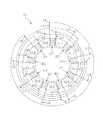
モータ16の構成の詳細について説明する。図2は、図1の線分II−IIにおけるステータ51の断面図である。図3は、モータ16の上面図である。図4は、図3の線分IV−IVにおけるモータ16の断面図である。(2) Configuration of Motor Details of the configuration of the motor 16 will be described. FIG. 2 is a cross-sectional view of the
モータ16は、9個の集中巻きコイルを有する集中巻きモータである。モータ16は、インバータ制御によって駆動される可変速モータである。モータ16は、U相、V相およびW相を有する3相モータである。 The motor 16 is a concentrated winding motor having nine concentrated winding coils. The motor 16 is a variable speed motor driven by inverter control. The motor 16 is a three-phase motor having a U phase, a V phase, and a W phase.
(2−1)ステータ
ステータ51は、主として、ステータコア61と、インシュレータ62,63とを有する。図4に示されるように、ステータコア61の鉛直方向の上端面61aには、インシュレータ62が取り付けられ、ステータコア61の鉛直方向の下端面61bには、インシュレータ63が取り付けられている。(2-1) Stator The
(2−1−1)ステータコア
ステータコア61は、電磁鋼からなる多数の円環状板が鉛直方向に積層された略円筒形状の部材である。ステータコア61の略円筒形状の軸方向は、鉛直方向である。(2-1-1) Stator Core The
ステータコア61は、ケーシング10に固定されている。具体的には、ステータコア61の外周面は、ケーシング10の内周面に溶接されている。溶接箇所は、ステータコア61の鉛直方向の両端部のそれぞれに3ケ所設けられている。溶接箇所は、ステータコア61の重量および固有振動数等により、適宜に決定されてもよい。ステータコア61は、圧入および焼嵌めによって、ケーシング10に固定されてもよい。 The
ステータコア61は、図2に示されるように、円筒部71と、9個のティース72とを有する。それぞれのティース72は、円筒部71の内周面から、円筒部71の径方向内側に向かって突出している。円筒部71の径方向は、鉛直方向に直交する水平面内にある。9個のティース72は、円筒部71の中心軸に対して9回対称となる位置に配置されている。すなわち、9個のティース72は、円筒部71の周方向に沿って、40度の角度間隔で等間隔に配置されている。 As shown in FIG. 2, the
ステータコア61の円筒部71の外周面には、図2に示されるように、9個のコアカット71aが形成されている。それぞれのコアカット71aは、円筒部71の上端面から下端面に亘り、円筒部71の中心軸に沿って切欠形成されている溝である。それぞれのコアカット71aは、ティース72から見て、円筒部71の径方向外側に位置している。9個のコアカット71aは、円筒部71の中心軸に対して9回対称となる位置に配置されている。すなわち、9個のコアカット71aは、円筒部71の周方向に沿って、40度の角度間隔で等間隔に配置されている。コアカット71aは、胴部11とステータ51との間を鉛直方向に延びる空間を形成する。 As shown in FIG. 2, nine
ステータコア61の各ティース72は、図3および図4に示されるように、インシュレータ62,63と共に、巻線73が巻き付けられている。これにより、図3に示されるように、ステータ51には、9個のコイルU1,U2,U3;V1,V2,V3;W1,W2,W3が形成されている。図3に示されるステータ51の上面図において、時計回りに、コイルU1,W3,V1,U2,W1,V2,U3,W2,V3が、この順で配置されている。巻線73は、複数のティース72に亘って巻き付けられておらず、9本の巻線73のそれぞれが、各ティース72に独立して巻き付けられている。すなわち、9個のコイルU1,U2,U3;V1,V2,V3;W1,W2,W3は、集中巻きコイルである。インシュレータ62,63は、ステータコア61と、巻線73とを絶縁している。巻線73は、銅線等の電気伝導体である。巻線73は、図3に示される白抜きの矢印に沿って、ステータ51の上面図において時計回りの方向に巻き付けられている。 As shown in FIGS. 3 and 4, each
コイルU1,U2,U3は、ステータコア61の周方向に120度の角度間隔で配置されているティース72のそれぞれに巻線73が巻かれて形成されている。コイルV1,V2,V3は、ステータコア61の周方向に120度の角度間隔で配置されているティース72のそれぞれに巻線73が巻かれて形成されている。コイルW1,W2,W3は、ステータコア61の周方向に120度の角度間隔で配置されているティース72のそれぞれに巻線73が巻かれて形成されている。コイルU1,U2,U3は、並列に結線され、モータ16のU相を形成する。コイルV1,V2,V3は、並列に結線され、モータ16のV相を形成する。コイルW1,W2,W3は、並列に結線され、モータ16のW相を形成する。図3に示されるように、ステータコア61の周方向に沿って隣り合う2つのコイルU1,U2,U3;V1,V2,V3;W1,W2,W3の間には、コイル間の隙間であるスロットSL1〜SL9が形成されている。図3に示されるステータ51の上面図において、スロットSL1は、コイルU1とコイルW3との間の隙間であり、スロットSL2〜SL9は、スロットSL1から時計回りに配置されている。 The coils U1, U2, and U3 are formed by winding a winding 73 around each of the
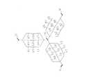
図5は、コイルU1,U2,U3;V1,V2,V3;W1,W2,W3の結線状態を示す図である。図5には、ステータコア61の上面図が示されているが、インシュレータ62は省略されている。図6は、図5に示される結線状態を簡略化した図である。 FIG. 5 is a diagram showing a connection state of the coils U1, U2, U3; V1, V2, V3; W1, W2, W3. FIG. 5 shows a top view of the
各コイルU1,U2,U3;V1,V2,V3;W1,W2,W3の巻線73の巻き始めの部分である9本の給電線e1〜e9は、ステータコア61の上端面61aの側から出ている。各コイルU1,U2,U3;V1,V2,V3;W1,W2,W3の巻線73の巻き終わりの部分である9本の中性線c1〜c9も、ステータコア61の上端面61aの側から出ている。 The nine power supply lines e1 to e9, which are the winding start portions of the
給電線e1〜e9は、巻線73の巻き始めの部分である。給電線e1,e4,e7は、それぞれ、コイルU1,U2,U3の巻線73から延び、U相の給電端子Uに接続される。給電線e3,e6,e9は、それぞれ、コイルV1,V2,V3の巻線73から延び、V相の給電端子Vに接続される。給電線e5,e8,e2は、それぞれ、コイルW1,W2,W3の巻線73から延び、W相の給電端子Wに接続される。3個の給電端子U,V,Wは、ケーシング10に取り付けられ、外部電源(図示せず)と接続されている。コイルU1,U2,U3;V1,V2,V3;W1,W2,W3のそれぞれにおいて、巻線73は巻き締め固定されている。 The feeder lines e1 to e9 are portions where the winding 73 starts to be wound. The feed lines e1, e4, e7 extend from the
中性線c1〜c9は、巻線73の巻き終わりの部分である。中性線c1,c4,c7は、それぞれ、コイルU1,U2,U3の巻線73から延び、中性点74に接続される。中性線c3,c6,c9は、それぞれ、コイルV1,V2,V3の巻線73から延び、中性点74に接続される。中性線c5,c8,c2は、それぞれ、コイルW1,W2,W3の巻線73から延び、中性点74に接続される。中性点74では、全ての中性線c1〜c9が電気的に接続されている。中性点74は、絶縁キャップ(図示せず)によって覆われて、何れかのスロットSL1〜SL9に挿入されている。絶縁キャップは、電気絶縁用のポリエステルフィルム等によって成形される。 Neutral wires c1 to c9 are winding end portions of the winding 73. Neutral wires c1, c4, and c7 extend from
給電線e1〜e9および中性線c1〜c9は、各コイルU1,U2,U3;V1,V2,V3;W1,W2,W3の巻線73の間の渡り線75である。図4に示されるように、渡り線75は、ステータコア61の上端面61aに取り付けられているインシュレータ62によって支持されている。渡り線75は、巻線73よりも上方の高さ位置において支持されている。渡り線75を支持するインシュレータ62の構造については後述する。 The feed lines e1 to e9 and the neutral lines c1 to c9 are connecting
(2−1−2)インシュレータ
インシュレータ62,63は、それぞれ、ステータコア61の鉛直方向の両端面61a,61bに取り付けられる絶縁体である。インシュレータ62,63は、例えば、液晶ポリマー(LCP)、ポリブチレンテレフタレート(PBT)、ポリフェニレンサルファイド(PPS)、ポリイミドおよびポリエステル等の高い耐熱性を有する樹脂から成型される。(2-1-2) Insulator The
図7は、ステータコア61の上端面61aに取り付けられているインシュレータ62の斜視図である。図8は、インシュレータ62の上面図である。図9は、図8の線分IX−IXにおいて切断したインシュレータ62の斜視図である。インシュレータ62は、主として、環状部62aと、9個の突出部62bと、9個の壁部62cと、9個の支持部62dとから構成されている。 FIG. 7 is a perspective view of the
環状部62aは、円環形状を有している。環状部62aは、ステータコア61の円筒部71の上端面と接触している。 The
突出部62bは、環状部62aの内周面から、環状部62aの径方向内側に向かって突出している。突出部62bは、環状部62aの周方向に沿って等間隔に配置されている。突出部62bは、ステータコア61のティース72の上端面と接触している。突出部62bの数は、円筒部71のティース72の数と同じである。突出部62bは、ティース72と共に巻線73が巻かれている。 The protruding
壁部62cは、環状部62aの上端面から、鉛直方向上方に向かって突出している。壁部62cは、環状部62aの周方向において隣接する突出部62bの間の空間の径方向外側に形成されている。壁部62cは、巻線73の径方向外側に形成されている。壁部62cの数は、突出部62bの数と同じである。 The
壁部62cは、第1内面81aおよび第1外面81bを有する。第1内面81aは、壁部62cの径方向内側の面である。第1外面81bは、壁部62cの径方向外側の面である。第1内面81aは、巻線73と対向する。第1外面81bは、径方向外側に向かって突出している補強部81cを有している。補強部81cは、壁部62cの強度を向上させるための部材である。 The
支持部62dは、壁部62cの上端部から、鉛直方向上方に向かって突出している。すなわち、支持部62dは、壁部62cよりも環状部62aから離れた位置にある。また、支持部62dは、環状部62aの周方向において隣接する2つの突出部62bの間の空間の径方向外側に形成されている。支持部62dは、巻線73から延びる渡り線75を支持する。 The
支持部62dは、第2内面82aおよび第2外面82bを有する。第2内面82aは、支持部62dの径方向内側の面である。第2外面82bは、支持部62dの径方向外側の面である。第2内面82aは、壁部62cの第1内面81aよりも径方向内側に位置する。第2外面82bは、壁部62cの第1外面81bよりも径方向内側に位置する。 The
支持部62dは、第2外面82bから径方向外側に向かって突出している複数の凸部82cを有している。複数の凸部82cは、図7に示されるように、鉛直方向において間隔を空けて形成されている。鉛直方向において、凸部82cの間には、渡り線75が配置される。これにより、渡り線75は、支持部62dによって支持される。渡り線75は、第2外面82bと接触している状態で支持されている。 The
なお、ステータコア61の下端面61bに取り付けられているインシュレータ63は、インシュレータ62から支持部62dを取り除いた構成を有している。しかし、インシュレータ63は、ステータコア61と巻線73とを絶縁することができる任意の構成を有していてもよい。 The insulator 63 attached to the
(2−2)ロータ
ロータ52は、ロータコア52aと、複数の磁石52bとを有する。ロータコア52aは、鉛直方向に積層された複数の金属板から構成される。磁石52bは、ロータコア52aに埋め込まれている。磁石52bは、ロータコア52aの周方向に沿って、等間隔に配置されている。(2-2) Rotor The
ロータ52は、クランクシャフト17に連結されている。クランクシャフト17は、ロータ52を鉛直方向に貫通する。ロータ52は、クランクシャフト17を介して、圧縮機構15と接続されている。 The
(3)圧縮機の動作
ロータリ圧縮機101の動作について説明する。モータ16が始動すると、ロータ52に連結されているクランクシャフト17の偏心軸部17aは、クランクシャフト17の回転軸を中心に偏心回転する。(3) Operation of Compressor The operation of the
クランクシャフト17の回転により、偏心軸部17aに連結されているピストン21は、圧縮室40において、クランクシャフト17の回転軸を中心とする公転運動を行う。ピストン21の公転運動によって、圧縮室40の吸入室および吐出室の容積が変化する。 Due to the rotation of the
低圧のガス冷媒は、吸入管19から圧縮室40の吸入室に吸入される。吸入室の容積は、ピストン21の公転運動によって減少する。これにより、吸入室の冷媒が圧縮され、吸入室は、高圧のガス冷媒が満たされた吐出室となる。高圧のガス冷媒は、吐出室から高圧空間S1に吐出される。吐出された冷媒は、鉛直方向上方に向かって、ステータ51とロータ52との間の空間であるエアギャップを通過する。その後、冷媒は、吐出管20からケーシング10の外部に吐出される。 The low-pressure gas refrigerant is sucked into the suction chamber of the
ケーシング10の油貯留部10aに貯留されている潤滑油は、主として、圧縮機構15の摺動部に供給される。圧縮機構15の摺動部に供給された潤滑油は、圧縮室40に流入する。圧縮室40において、潤滑油は、微小な油滴となって、冷媒ガスに混入する。そのため、圧縮機構15から吐出された圧縮冷媒は、潤滑油を含んでいる。圧縮冷媒に含まれる潤滑油の一部は、モータ16の上方の高圧空間S1において、冷媒の流れによる遠心力によって冷媒から分離され、ケーシング10の内周面に付着する。ケーシング10の内周面に付着した潤滑油は、ケーシング10の内周面を伝って落下して、モータ16のステータ51の上面の高さ位置に到達する。そして、潤滑油は、ステータコア61のコアカット71aを通過して落下する。コアカット71aを通過した潤滑油は、最終的に、油貯留部10aに戻る。 The lubricating oil stored in the
(4)特徴
モータ16のインシュレータ62は、渡り線75を支持する支持部62dを有している。図10は、ロータリ圧縮機101のインシュレータ62の近傍の拡大図である。支持部62dの第2外面82bと、ケーシング10の胴部11の内周面11aとの間には、絶縁隙間84が形成されている。渡り線75は、絶縁隙間84において、支持部62dの第2外面82bと接触している状態で支持されている。(4) Features The
支持部62dの第2内面82aは、壁部62cの第1内面81aよりも径方向内側に位置している。これにより、支持部62dの第2外面82bが、壁部62cの第1外面81bよりも径方向内側に位置するように、壁部62cの上端に支持部62dを連結させることができる。支持部62dの第2外面82bの位置が径方向内側にあるほど、絶縁隙間84の径方向の寸法が大きくなる。そのため、支持部62dは、渡り線75と、胴部11の内周面11aとの間の距離を十分に確保することができる。 The second
渡り線75とケーシング10との間の距離は、法律上の規格を満たす必要がある。そのため、一般的に、ステータコア61の円筒部71の径方向の寸法を短くしてモータ16を小型化することは困難である。しかし、インシュレータ62は、支持部62dによって渡り線75を支持することにより、渡り線75とケーシング10との間の距離を十分に確保することができる。そのため、モータ16は、渡り線75とケーシング10との間の距離を確保しつつ、ステータコア61の円筒部71の径方向の寸法を短くすることができる。従って、本実施形態のモータ16は、小型化を達成することができる。 The distance between the
また、モータ16のコイルU1,U2,U3;V1,V2,V3;W1,W2,W3は、ステータコア61の各ティース72に巻線73を巻き付けることによって形成される集中巻きコイルである。集中巻きコイルの製造方法は、例えば、巻線73を放出する巻線ノズル(図示せず)を用いて、全てのティース72に巻線73を同時に巻き付ける同時巻き法である。同時巻き法では、インシュレータ62が取り付けられたステータコア61を固定した状態で、9個の巻線ノズルを9個のティース72の周囲で移動させて、全てのティース72に巻線73が同時に巻き付けられる。 The coils U1, U2, U3; V1, V2, V3; W1, W2, W3 of the motor 16 are concentrated winding coils formed by winding the winding 73 around each
本実施形態では、モータ16を鉛直方向に沿って見た場合において、壁部62cおよび支持部62dは、スロットSL1〜SL9の径方向外側に形成されている。そのため、巻線ノズルでティース72に巻線73を巻き付ける際に、巻線ノズルが壁部62cおよび支持部62dと干渉しにくい。また、巻線ノズルは、ティース72に巻線73を巻き付けた後、支持部62dの第2外面82bに渡り線75を巻き付けることにより、渡り線75をインシュレータ62に固定することができる。また、巻線ノズルは、渡り線75の結線工程を機械的に行うことができる。結線工程では、9本の給電線e1〜e9が、3個の給電端子U,V,Wに接続され、かつ、9本の中性線c1〜c9が、中性点74に接続される。従って、本実施形態では、巻線ノズルを用いて、ティース72に巻線73を巻き付けて渡り線75を固定することができるので、モータ16の製造に必要な工数およびコストが削減される。 In the present embodiment, when the motor 16 is viewed along the vertical direction, the
(5)変形例
(5−1)変形例A
実施形態において、インシュレータ62は、9個の支持部62dを有している。支持部62bは、壁部62cの上端部と連結されている。すなわち、支持部62bは、壁部62cのみと連結されている。しかし、支持部62bは、壁部62c以外の他の部材とさらに連結されていてもよい。(5) Modification (5-1) Modification A
In the embodiment, the
図11は、本変形例のインシュレータ162の斜視図である。インシュレータ162は、主として、環状部162aと、9個の突出部162bと、9個の壁部162cと、9個の支持部162dと、連結部162eとから構成されている。インシュレータ162と、実施形態のインシュレータ62との相違点は、連結部162eのみである。環状部162a、突出部162b、壁部162cおよび支持部162dは、それぞれ、実施形態の環状部62a、突出部62b、壁部62cおよび支持部62dに相当する。 FIG. 11 is a perspective view of an
連結部162eは、円環形状の部材である。連結部162eは、9個の支持部162dの上端部と連結されている。連結部162eは、支持部162dと一体的に形成されてもよく、支持部162dとは独立した部材として形成されてもよい。連結部162eは、支持部162dの強度を向上させるための部材である。従って、連結部162eは、インシュレータ162の強度を向上させることができる。 The connecting
(5−2)変形例B
実施形態において、ステータコア61の上端面61aに取り付けられるインシュレータ62は、支持部62dを有するが、ステータコア61の下端面61bに取り付けられるインシュレータ63は、支持部62dを有さない。しかし、ステータコア61の上端面61aに取り付けられるインシュレータ62の代わりに、ステータコア61の下端面61bに取り付けられるインシュレータ63が、支持部62dを有してもよい。(5-2) Modification B
In the embodiment, the
(5−3)変形例C
実施形態では、支持部62dを有するインシュレータ62を有するステータ51を備える圧縮機として、ロータリ圧縮機101が用いられているが、スクロール圧縮機等の他の圧縮機が用いられてもよい。(5-3) Modification C
In the embodiment, the
本発明に係るステータおよびモータは、モータの小型化を達成することができる。 The stator and motor according to the present invention can achieve miniaturization of the motor.
16 モータ
51 ステータ
52 ロータ
61 ステータコア
62 インシュレータ
62a 環状部
62b 突出部
62c 壁部
62d 支持部
72 ティース
73 巻線
75 渡り線
81a 第1内面
82a 第2内面
81b 第1外面
82b 第2外面
162e 連結部16
Claims (7)
Translated fromJapanese前記ステータコアの軸方向の端面に取り付けられるインシュレータ(62)と、
を備え、
前記インシュレータは、
環状部(62a)と、
前記環状部の内周面から、前記環状部の径方向の内側に向かって突出し、かつ、前記環状部の周方向に沿って配置され、かつ、前記ティースと共に巻線(73)が巻かれる複数の突出部(62b)と、
前記巻線よりも前記径方向の外側に位置する複数の壁部(62c)と、
前記軸方向において前記壁部よりも前記環状部から離れた位置にあり、かつ、前記巻線から延びる渡り線(75)を支持する複数の支持部(62d)と、
を有し、
前記壁部は、前記径方向の内側の面であり、かつ、前記巻線と対向する第1内面(81a)を有し、
前記支持部は、前記径方向の内側の面であり、かつ、前記第1内面よりも前記径方向の内側に位置する第2内面(82a)を有する、
ステータ(51)。A stator core (61) having a plurality of teeth (72);
An insulator (62) attached to an axial end surface of the stator core;
With
The insulator is
An annular portion (62a);
A plurality of windings (73) that protrude from the inner peripheral surface of the annular portion toward the inner side in the radial direction of the annular portion, are arranged along the circumferential direction of the annular portion, and are wound with the teeth. A protrusion (62b) of
A plurality of wall portions (62c) located outside the winding in the radial direction,
A plurality of support portions (62d) that are located at a position farther from the annular portion than the wall portion in the axial direction and support the crossover (75) extending from the winding;
Have
The wall portion is a radially inner surface and has a first inner surface (81a) facing the windings,
The support portion has a second inner surface (82a) which is an inner surface in the radial direction and is located on the inner side in the radial direction with respect to the first inner surface.
Stator (51).
前記支持部は、前記径方向の外側の面であり、かつ、前記第1外面よりも前記径方向の内側にある第2外面(82b)を有する、
請求項1に記載のステータ。The wall portion has a first outer surface (81b) which is an outer surface in the radial direction,
The support portion has a second outer surface (82b) that is a surface on the outer side in the radial direction and is located on the inner side in the radial direction with respect to the first outer surface.
The stator according to claim 1.
前記支持部は、前記壁部の前記軸方向の端部であって、前記環状部が位置する側の反対側の端部から、前記環状部から離れる方向に延びている、
請求項1または2に記載のステータ。The wall portion is an end portion in the axial direction of the annular portion, and extends in a direction away from the stator core from an end portion on the opposite side to the side where the stator core is located,
The support portion is an end portion in the axial direction of the wall portion, and extends in a direction away from the annular portion from an end portion on the opposite side to the side where the annular portion is located.
The stator according to claim 1 or 2.
請求項1から3のいずれか1項に記載のステータ。The support portion is located between the protruding portions in the circumferential direction.
The stator according to any one of claims 1 to 3.
請求項1から4のいずれか1項に記載のステータ。The support portion supports the connecting wire at a position farther from the annular portion than the winding in the axial direction.
The stator according to any one of claims 1 to 4.
請求項1から5のいずれか1項に記載のステータ。A connecting portion (162e) that is an annular member that connects the support portions;
The stator according to any one of claims 1 to 5.
前記ステータの内側に配置されるロータ(52)と、
を備える、モータ(16)。The stator according to any one of claims 1 to 6,
A rotor (52) disposed inside the stator;
A motor (16) comprising:
Priority Applications (1)
| Application Number | Priority Date | Filing Date | Title |
|---|---|---|---|
| JP2014202305AJP2016073137A (en) | 2014-09-30 | 2014-09-30 | Stator and motor |
Applications Claiming Priority (1)
| Application Number | Priority Date | Filing Date | Title |
|---|---|---|---|
| JP2014202305AJP2016073137A (en) | 2014-09-30 | 2014-09-30 | Stator and motor |
Publications (1)
| Publication Number | Publication Date |
|---|---|
| JP2016073137Atrue JP2016073137A (en) | 2016-05-09 |
Family
ID=55865131
Family Applications (1)
| Application Number | Title | Priority Date | Filing Date |
|---|---|---|---|
| JP2014202305APendingJP2016073137A (en) | 2014-09-30 | 2014-09-30 | Stator and motor |
Country Status (1)
| Country | Link |
|---|---|
| JP (1) | JP2016073137A (en) |
Cited By (2)
| Publication number | Priority date | Publication date | Assignee | Title |
|---|---|---|---|---|
| CN106059156A (en)* | 2016-07-26 | 2016-10-26 | 珠海格力节能环保制冷技术研究中心有限公司 | Stator assembly and its manufacturing method and plastic package motor |
| US11063482B2 (en) | 2016-07-28 | 2021-07-13 | Samsung Electronics Co., Ltd. | Stator and motor having the same |
- 2014
- 2014-09-30JPJP2014202305Apatent/JP2016073137A/enactivePending
Cited By (2)
| Publication number | Priority date | Publication date | Assignee | Title |
|---|---|---|---|---|
| CN106059156A (en)* | 2016-07-26 | 2016-10-26 | 珠海格力节能环保制冷技术研究中心有限公司 | Stator assembly and its manufacturing method and plastic package motor |
| US11063482B2 (en) | 2016-07-28 | 2021-07-13 | Samsung Electronics Co., Ltd. | Stator and motor having the same |
Similar Documents
| Publication | Publication Date | Title |
|---|---|---|
| US9608490B2 (en) | Compressor | |
| KR101378024B1 (en) | Motor-driven compressor | |
| US9369022B2 (en) | Electric motor and fuel pump using the same having circumferential holding grooves for beginning and end portions of coil windings | |
| US20180245597A1 (en) | Electric fluid pump | |
| KR101573970B1 (en) | Electric Compressor | |
| JP6489183B2 (en) | Stator, manufacturing method thereof, motor and compressor using the stator | |
| US8405274B2 (en) | Motor stator and phase coil preform | |
| US11005325B2 (en) | Rotating electric machine, stator of rotating electric machine, and compressor | |
| CN107005119B (en) | Stator and motor | |
| JP7285097B2 (en) | Open wound motors, compressors, and refrigeration cycle equipment | |
| JP6987235B2 (en) | A stator and a motor equipped with the stator | |
| JP2016073137A (en) | Stator and motor | |
| JP2018011394A (en) | Insulator and method for manufacturing insulator | |
| JP2014171333A (en) | Motor and compressor | |
| JP2023044187A (en) | Electric motor and hermetic electric compressor comprising the electric motor | |
| JP2021005992A (en) | Motor, compressor, and manufacturing method of motor | |
| CN111247719B (en) | Stator, motor and compressor | |
| JP2009177970A (en) | Stator, motor and compressor | |
| JP6135632B2 (en) | Compressor | |
| JP2019176638A (en) | Three-phase motor and compressor |