JP2016062903A - Laminated semiconductor element and manufacturing method thereof - Google Patents
Laminated semiconductor element and manufacturing method thereofDownload PDFInfo
- Publication number
- JP2016062903A JP2016062903AJP2014186694AJP2014186694AJP2016062903AJP 2016062903 AJP2016062903 AJP 2016062903AJP 2014186694 AJP2014186694 AJP 2014186694AJP 2014186694 AJP2014186694 AJP 2014186694AJP 2016062903 AJP2016062903 AJP 2016062903A
- Authority
- JP
- Japan
- Prior art keywords
- layer
- semiconductor
- wiring
- semiconductor circuit
- circuit
- Prior art date
- Legal status (The legal status is an assumption and is not a legal conclusion. Google has not performed a legal analysis and makes no representation as to the accuracy of the status listed.)
- Pending
Links
Images


Landscapes
- Internal Circuitry In Semiconductor Integrated Circuit Devices (AREA)
- Metal-Oxide And Bipolar Metal-Oxide Semiconductor Integrated Circuits (AREA)
- Thin Film Transistor (AREA)
Abstract
Translated fromJapaneseDescription
Translated fromJapanese本発明は、半導体回路が積層された3次元構造を有する積層型半導体素子及びその製造方法に関するものである。 The present invention relates to a stacked semiconductor element having a three-dimensional structure in which semiconductor circuits are stacked and a method for manufacturing the same.
半導体集積回路の大規模化、高密度化を実現するため、半導体回路を3次元的に積層した、積層型半導体素子が注目されている。例えば特許文献1には、SOI(Silicon on insulator)基板に形成したMOS(Metal-Oxide-Semiconductor)トランジスタを積層する製造方法が記述されている。 In order to realize an increase in scale and density of a semiconductor integrated circuit, a stacked semiconductor element in which semiconductor circuits are stacked three-dimensionally has attracted attention. For example,
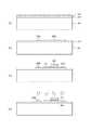
図7に従来の積層型半導体素子の断面構造の一例を示す。図7は4層の半導体回路を積層した例であるが、特定の機能を持つ回路を示したものではなく、配線も一部省略している。 FIG. 7 shows an example of a cross-sectional structure of a conventional stacked semiconductor element. FIG. 7 shows an example in which four layers of semiconductor circuits are stacked, but does not show a circuit having a specific function, and some wirings are also omitted.
同図において、支持基板100の上に、第1層半導体回路10、第2層半導体回路20、第3層半導体回路30、及び第4層半導体回路40が順次積層されている。各々の単層半導体回路は、支持基板100又は下層の半導体回路と接合又は接着されており、各層の絶縁層内の単結晶シリコンからなる能動素子(代表的には、MOSトランジスタ)により集積回路が構成されている。 In the figure, a first
ここで、第1層半導体回路10とは、BOX層(Buried Oxide層、埋め込み絶縁層)110の下面から、内部に単結晶シリコン層120からなる能動素子(MOSトランジスタ101)及び配線層151,152を含む絶縁層130の上面までの領域であり、このBOX層110の下面と、絶縁層130の上面が、第1層半導体回路10の2つの主面となる。同様に、単層半導体回路(20,30,40)とは、各BOX層(210,310,410)の下面から各層の能動素子を覆う絶縁層(230,330,430)の上面までを意味する。絶縁層は、複数の絶縁膜から構成されて良く、層間絶縁膜ということもある。 Here, the first-
積層型半導体素子では、多くの場合、上下の層間を接続する層間配線が使われる。図7の積層型半導体素子では、2種類の層間配線510,520が示されており、層間配線510は第1層と第3層の半導体回路を接続する配線、層間配線520は第1層と第2層の回路を接続する配線である。層間配線520は特許文献1に記載された構造を有しており、直上/直下の回路(第2層半導体回路20のMOSトランジスタ201のソース/ドレイン領域205と、第1層半導体回路10の第2の配線152)を接続しているため、配線の断面積はトランジスタのソース/ドレイン領域と同程度である。他方、層間配線510は複数層の半導体回路を貫通するため、層間配線520に比べて配線の断面積が大きい。 In a stacked semiconductor element, interlayer wiring that connects upper and lower layers is often used. In the stacked semiconductor element of FIG. 7, two types of
図7の積層型半導体素子の製造方法を、図面を参照して説明する。本製造方法は、特許文献1の方法をベースとしている。 A method for manufacturing the stacked semiconductor device of FIG. 7 will be described with reference to the drawings. This manufacturing method is based on the method of
図8〜図12は、図7に示す従来の積層型半導体素子の製造方法の一例を、工程順に示したものである。なお、(a)〜(j)の記号は、製造工程順序を意味し、複数の図面をまたいで付与されている。 8 to 12 show an example of the manufacturing method of the conventional stacked semiconductor element shown in FIG. 7 in the order of steps. The symbols (a) to (j) mean the manufacturing process sequence, and are given across a plurality of drawings.
図8(a)は第1層半導体回路10の構造を示したものである。まず、一般的な半導体製造技術を用いてSOI基板を作製する。SOI基板は、絶縁層上の単結晶シリコン層を活性層として利用するものであり、例えば、特許文献1に記載されるように、シリコン基板に酸素イオン等を所定の深さまでイオン注入して、BOX層(埋め込み絶縁層)110を形成することにより、シリコン基板のBOX層110より下部が支持基板100となり、また、BOX層110の上の単結晶シリコン層(シリコン基板の一部)120を活性層とすることで実現される。このようなSOI基板は一般に市販されており、適宜の基板を使用することができる。このSOI基板の活性層にMOSトランジスタ101を形成する。 FIG. 8A shows the structure of the first
MOSトランジスタ101は、一般的なアイソレーション(素子分離)の技術により、単結晶シリコン層120をエッチング等により島状の領域に形成して活性層102とし、次いで、ゲート絶縁膜103、ゲート電極104、ソース/ドレイン領域105を形成して作製される。その後、表面に酸化膜等の第1の絶縁層130と、MOSトランジスタ101に接続する第1の配線151及び第2の配線152を形成する。なお、説明を簡単にするため、配線層は第1の配線151と第2の配線152の2層の配線としたが、より多層の配線層を形成してもよい。また、第1の絶縁層130は、実際には多層の絶縁膜から構成されることが多い。その後、CMP(Chemical Mechanical Polishing:化学機械研磨)により素子表面(絶縁層表面)を平坦化する。これにより、第1層の半導体回路10が完成する。 In the
図8(a)では、第1の配線151、第2の配線152は、それぞれ、半導体基板に対して垂直方向に伸びる縦方向の配線(層間配線)として用いるものとして記載されているが、同時に、半導体基板主面に対して並行に伸びる横方向の配線(層内配線)として利用することも可能である。ここで、図8(a)の左側の第2の配線152は、右側の第2の配線152よりも面積が広く形成されているが、これは、後に比較的断面積の大きい層間配線510と接続するためである。 In FIG. 8A, the
次に、図8(b)に示されるように、第2層半導体回路20を作製する。図8(a)と同様に一般的な半導体製造技術を用いてSOI構造のMOSトランジスタ201を作製する。第1層半導体回路10と同様に、BOX層(埋め込み絶縁層)210上の単結晶シリコン層220をパターニングして活性層202を形成し、この活性層202に、ゲート絶縁膜203、ゲート電極204、ソース/ドレイン領域205を形成して、MOSトランジスタ201を作製する。その後、第2の絶縁層230を形成し、MOSトランジスタ201に接続する第1の配線251及び第2の配線252を形成することで、図8(b)のSOI構造MOSトランジスタ201が完成する。 Next, as shown in FIG. 8B, the second
次に、MOSトランジスタ201を覆う絶縁層230の上部に、仮基板200を樹脂等を用いて貼り付け、図8(c)のごとく、第2層半導体回路20の表面に仮基板200を仮接着する。その後、支持基板100を、例えばCMP(化学機械研磨)やエッチングにより除去する。そして、支持基板100を除去した側(裏面側)から、絶縁層(BOX層)210に開口を形成し、MOSトランジスタのソース/ドレイン領域205に接続する接合電極(又は配線)253を形成する。この接合電極253は、後に層間配線520として機能する。これで、積層半導体素子のための第2層半導体回路20が完成する。 Next, the
図9(d)に、2層の半導体回路の積層構造を示す。図8(a)で作製した第1層半導体回路10の上に、図8(c)の第2層半導体回路20を、第1層半導体回路10の第2の配線152と第2層の接合電極253とが接続するよう、電極・配線等の位置合わせを行って積層し、直接接合技術等により接合した後、仮基板200を剥離又は除去する。
このようにして、図9(d)の第1層半導体回路10と第2層半導体回路20とが積層され、MOSトランジスタ101とMOSトランジスタ201が接続された3次元構造集積回路が作製される。FIG. 9D shows a stacked structure of a two-layer semiconductor circuit. The second
In this way, the first-
以下、同様の工程を繰り返して、第3層以降の半導体回路を積層する。 Thereafter, the same steps are repeated to stack the third and subsequent semiconductor circuits.
まず、MOSトランジスタ301が形成された第3層半導体回路30を、第2層半導体回路20と同様に、図8(b)、(c)に示した工程で作製する。ただし、第3半導体回路30では、接合電極は形成しない。そして、図9(e)のように、第2層半導体回路20の上に第3層半導体回路30を積層する。 First, the third
次に、第1層半導体回路10と第3層半導体回路30とを接続する層間配線510の製造工程を説明する。 Next, a manufacturing process of the
図10(f)において、第3層半導体回路30の絶縁層331の表面から、第1層半導体回路10の左側の第2の配線152に達する貫通ビアホール501を形成する。 In FIG. 10 (f), a through via
次いで、図10(g)のように、スパッタやメッキにより、後に層間配線となる金属層502で貫通ビアホール501を埋める。このとき、金属層502は第3層半導体回路30の表面を覆って形成する。 Next, as shown in FIG. 10G, the through via
そして、図11(h)のとおり、通常のフォトリソグラフィ及びエッチング技術により、表面の金属層502をパターニングして不要部分を除去し、第3層半導体回路30の第2の配線352と接触する第3の配線353を形成する。第3の配線353の一部は、層間配線510と一体化しており、第3層の第2の配線352を、層間配線510を介して第1層の第2の配線152と接続する。これにより、第1層のMOSトランジスタ101と第3層のMOSトランジスタ301が電気的に接続される。 Then, as shown in FIG. 11H, the
次いで、図11(i)のとおり、絶縁層332をCVD等で形成して第3の配線353を覆う。 Next, as illustrated in FIG. 11I, the insulating
その後、図12(j)に示すように、表面をCMP等で平坦化し、絶縁層332及び第3の配線353を所定の厚さとし、第3の絶縁層330内に配線層351,352,353を備えた第3層半導体回路30を形成する。 After that, as shown in FIG. 12J, the surface is flattened by CMP or the like, the insulating
以上の工程で、第3層の半導体回路30まで完成する。 Through the above steps, the third-
さらに、その後、第2層半導体回路20及び第3層半導体回路30と同様の手順で第4層半導体回路40を形成し、第3層半導体回路30の上に位置合わせして積層する。 Further, after that, a fourth
このようにして、図7の第1層から第4層の半導体回路を有する積層型半導体素子が完成する。 In this manner, a stacked semiconductor element having the first to fourth semiconductor circuits in FIG. 7 is completed.
従来の積層型半導体素子においては、積層の途中で層間配線510を形成する特別な工程(図10〜図12)が必要である。また、貫通ビアホール501は複数の層を貫通して形成されるため、層間配線510は接合電極253(層間配線520)に比べ、断面積が大きくなる。また、貫通ビアホール501は、下層のMOSトランジスタ等が存在しない領域に形成することが必要であり、レイアウトの自由度が低く、且つ迂回配線となりやすい。そのため、素子面積に対して層間配線が占める割合が大きくなり、積層化によって集積度を上げようとする素子本来の目的を達成するために障害となるという問題がある。 In the conventional laminated semiconductor element, a special process (FIGS. 10 to 12) for forming the
例えば、図7において、単層の半導体回路層の厚さが10μm程度であるとすると、第2層半導体回路20と第3層半導体回路30とを貫通する貫通ビアホール501の深さは20μm程度となる。異方性ドライエッチングを用いてビアホールを形成するとしても、安定した断面形状に開口を形成するためには、ビアホールのアスペクト比を4:1以下にすることが望ましいから、貫通ビアホール501の開口径を5μm以上とすることが必要となる。 For example, in FIG. 7, if the thickness of the single semiconductor circuit layer is about 10 μm, the depth of the through via
図7の例では、層間配線510は第1層と第3層を接続するため2層を貫通しているが、多層積層の素子においては、数層以上を貫通する配線が必要になることがある。その場合、層間配線の距離がさらに長くなるため(ビアホールの深さが深くなるため)、貫通ビアホール501はより大きな径で開口しなければならず、結果として層間配線はさらに断面積が大きくなる。 In the example of FIG. 7, the
従って、上記のような問題点に鑑みてなされた本発明の目的は、半導体回路を3次元的に積層する積層型半導体素子において、回路の高集積化に有利な層間配線の構造を提供することにある。また、特別な工程を用いることなく、積層型半導体素子の層間配線を製造する方法を提供することにある。 Accordingly, an object of the present invention made in view of the above problems is to provide an interlayer wiring structure that is advantageous for high integration of a circuit in a stacked semiconductor element in which semiconductor circuits are three-dimensionally stacked. It is in. It is another object of the present invention to provide a method for manufacturing an interlayer wiring of a stacked semiconductor element without using a special process.
上記課題を解決するために本発明に係る積層型半導体素子は、単層半導体回路を複数層積層してなる積層型半導体素子であって、少なくとも一つの前記単層半導体回路は、前記単層半導体回路の第1及び第2の主面の間を貫通する層間配線を備え、前記層間配線は、不純物が導入された半導体層と、前記第1及び第2の主面に露出する前記半導体層よりも高導電性の材料とを備えることを特徴とする。 In order to solve the above problems, a stacked semiconductor device according to the present invention is a stacked semiconductor device formed by stacking a plurality of single-layer semiconductor circuits, and at least one single-layer semiconductor circuit includes the single-layer semiconductor circuit. An interlayer wiring penetrating between the first and second main surfaces of the circuit is provided. The interlayer wiring includes a semiconductor layer into which an impurity is introduced and the semiconductor layer exposed to the first and second main surfaces. Is also provided with a highly conductive material.
また、前記半導体層は、能動素子を形成しない、独立した半導体島領域であることが望ましい。 The semiconductor layer is preferably an independent semiconductor island region that does not form an active element.
また、前記半導体層は、単結晶半導体からなることが望ましい。 The semiconductor layer is preferably made of a single crystal semiconductor.
また、前記半導体層よりも高導電性の材料は、金属であることが望ましい。 In addition, the material having higher conductivity than the semiconductor layer is preferably a metal.
上記課題を解決するために本発明に係る積層型半導体素子の製造方法は、単層半導体回路を複数層積層してなる積層型半導体素子の製造方法であって、少なくとも一つの前記単層半導体回路の半導体層に不純物を導入して不純物拡散半導体層を形成する工程と、前記単層半導体回路の第1の主面側から、前記不純物拡散半導体層に接続する前記不純物拡散半導体層よりも高導電性の材料からなる配線を形成する工程と、前記単層半導体回路の第2の主面側から、前記不純物拡散半導体層に接続する前記不純物拡散半導体層よりも高導電性の材料からなる配線を形成する工程と、を備え、前記単層半導体回路の第1及び第2の主面の間を貫通する層間配線を形成することを特徴とする。 In order to solve the above problems, a manufacturing method of a stacked semiconductor device according to the present invention is a manufacturing method of a stacked semiconductor device in which a plurality of single-layer semiconductor circuits are stacked, and includes at least one single-layer semiconductor circuit. A step of introducing an impurity into the semiconductor layer to form an impurity diffusion semiconductor layer, and a higher conductivity than the impurity diffusion semiconductor layer connected to the impurity diffusion semiconductor layer from the first main surface side of the single-layer semiconductor circuit Forming a wiring made of a conductive material, and a wiring made of a material that is higher in conductivity than the impurity diffusion semiconductor layer connected to the impurity diffusion semiconductor layer from the second main surface side of the single-layer semiconductor circuit. Forming an interlayer wiring penetrating between the first and second main surfaces of the single-layer semiconductor circuit.
また、前記不純物拡散半導体層を形成する工程は、能動素子を形成しない独立した半導体島領域に不純物を導入することが望ましい。 In the step of forming the impurity diffusion semiconductor layer, it is desirable to introduce impurities into an independent semiconductor island region where no active element is formed.
また、前記不純物拡散半導体層を形成する工程は、トランジスタのソース/ドレイン領域の形成と同時に前記不純物拡散半導体層を形成することが望ましい。 In the step of forming the impurity diffusion semiconductor layer, the impurity diffusion semiconductor layer is preferably formed simultaneously with the formation of the source / drain regions of the transistor.
また、前記不純物拡散半導体層は、単結晶半導体からなることが望ましい。 The impurity diffusion semiconductor layer is preferably made of a single crystal semiconductor.
また、前記半導体層よりも高導電性の材料は、金属であることが望ましい。 In addition, the material having higher conductivity than the semiconductor layer is preferably a metal.
本発明の構造によれば、積層型半導体素子の層間配線の断面積を従来の構造に比べ小さくすることができるため、積層型半導体素子(3次元集積回路)全体の集積度を向上させることができる。また、本発明の製造方法は、従来の積層型半導体素子の素子形成と同時に垂直方向の配線構造を形成でき、層間配線の形成に特別な工程を付加する必要がないため、製造コストの上昇を抑えることができる。 According to the structure of the present invention, the cross-sectional area of the interlayer wiring of the stacked semiconductor element can be reduced as compared with the conventional structure, so that the integration degree of the entire stacked semiconductor element (three-dimensional integrated circuit) can be improved. it can. In addition, the manufacturing method of the present invention can form a vertical wiring structure simultaneously with the element formation of the conventional stacked semiconductor element, and does not require any special process for forming the interlayer wiring, thus increasing the manufacturing cost. Can be suppressed.
以下、本発明の実施の形態について説明する。 Embodiments of the present invention will be described below.
(第1の実施例)
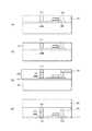
本発明による積層型半導体素子の構造の第1の実施例を図1に示す。図1の積層型半導体素子は、図7に示した従来構造と同じ配線接続を有する3次元集積回路を構成している。(First embodiment)
A first embodiment of the structure of a stacked semiconductor device according to the present invention is shown in FIG. 1 constitutes a three-dimensional integrated circuit having the same wiring connection as that of the conventional structure shown in FIG.
本発明では、第2層半導体回路20の第1の主面(上面)と第2の主面(下面)の間に、第2の配線252、第1の配線251、高濃度拡散層(不純物拡散半導体層)205B、及び接合電極253を配置して接続することで、第1の主面(上面)と第2の主面(下面)の間を貫通する層間配線510を構成し、第1層と第3層を接続する配線を形成している。ここで、高濃度拡散層205Bは、不純物が高濃度に導入された半導体層であり、不純物拡散半導体層とも呼ぶ(ただし、不純物の導入方法は拡散法に限らず、イオン注入等任意の方法を用いてよい)。この半導体層は、能動素子を形成するための半導体層と同時に形成されたものであり、単結晶半導体層であることが望ましい。また、第1の配線251、第2の配線252、及び接合電極(又は配線)253は、高濃度拡散層205Bよりも高導電性の材料、具体的には、金、銅、アルミニウム等の金属や、CoSi,WSi等のシリサイド、さらに、TiN等の金属窒化物等を用いることができる。 In the present invention, between the first main surface (upper surface) and the second main surface (lower surface) of the second
図1の例では、第3層半導体回路30も、接合電極354と、高濃度拡散層305Bと、高濃度拡散層305BとMOSトランジスタのソース/ドレイン領域305とを接続する第1の配線351を備えており、第3層半導体回路30内での配線構造の微細化を図っている。この構造では、貫通ビアホールを形成する必要がなく、層間配線の配線断面積を小さくできる。第1、第2の配線、高濃度拡散層、接合電極を順次接続することで層間を接続するため、それぞれの接続部の配線断面積が最小化され、従来構造にくらべて、回路の集積度を向上させることができる。さらに、層間を接続する際に、層が増えても層間配線の配線断面積は大きくならないため多層積層構造の素子においては、従来技術からの改善効果が顕著である。 In the example of FIG. 1, the third
また、この構造では、高濃度拡散層205Bは、ソース/ドレイン領域205と同時に形成でき、特別な貫通ビアホールの形成や貫通ビアホールへの導電体埋設工程も不要であるため、従来技術で各層の回路を形成した後、順次積層していくだけで、積層型半導体素子が製造できる。すなわち、従来構造の素子を製造するために不可欠であった図10(f)〜図12(j)の工程は不要となり、製造工程を簡略化することができる。 In this structure, the high-
なお、本発明の構造では、層間配線の途中に高濃度拡散層(不純物拡散半導体層)205Bが挿入される。高濃度拡散層は金属に比べ抵抗率が高いため、その影響で、層間配線の抵抗が上がることが懸念されるが、例えば、高濃度に不純物を導入した半導体層において信号電流の通る断面積Sを10-8 cm2、信号電流の通る距離L(ソース/ドレイン層205の厚さに等しい)を10-5cmとし、高濃度拡散層の抵抗率ρを10-4(Ω・cm)とすると、高濃度拡散層の抵抗Rは、R=ρL/Sより、0.1Ωとなる。この程度の抵抗であれば、一般の論理回路の動作には支障はなく、本発明の構造は十分実用的であるといえる。In the structure of the present invention, a high concentration diffusion layer (impurity diffusion semiconductor layer) 205B is inserted in the middle of the interlayer wiring. Since the high-concentration diffusion layer has a higher resistivity than metal, there is a concern that the resistance of the interlayer wiring may increase due to the influence. For example, a cross-sectional area S through which a signal current passes in a semiconductor layer doped with a high concentration of impurities.Is 10−8 cm2 , the distance L through which the signal current passes (equal to the thickness of the source / drain layer 205) is 10−5 cm, and the resistivity ρ of the high-concentration diffusion layer is 10−4 (Ω · cm). Then, the resistance R of the high concentration diffusion layer is 0.1Ω from R = ρL / S. With such a resistance, the operation of a general logic circuit is not hindered, and the structure of the present invention can be said to be sufficiently practical.
(本発明の層間配線の製造方法)
図1〜図4を用いて、本発明の積層型半導体素子の製造方法を説明する。なお、(a)〜(j)の記号は、製造工程順序を意味し、複数の図面をまたいで付与されている。(Method for producing interlayer wiring of the present invention)
A method for manufacturing a stacked semiconductor device of the present invention will be described with reference to FIGS. The symbols (a) to (j) mean the manufacturing process sequence, and are given across a plurality of drawings.
本発明の層間配線は、層間配線を形成するために特別な工程を付加することなく、一般的な半導体集積回路の製造工程と、積層工程を組み合わせることで作製可能である。以下の製造工程では、層間配線について構造的な特徴を備えた第2層半導体回路20の製造を中心に説明する。 The interlayer wiring of the present invention can be manufactured by combining a general semiconductor integrated circuit manufacturing process and a stacking process without adding a special process for forming the interlayer wiring. In the following manufacturing process, description will be made centering on the manufacture of the second
本発明の積層型半導体素子の第1層半導体回路10は、図1の最下層10の構造を有する。 The first
第1層半導体回路10の製造工程は、従来の図8(a)の半導体回路の製造工程と同様であり、一般的な半導体製造技術を用いることができる。まず、支持基板100、BOX層110、単結晶半導体層120からなるSOI基板を準備する。 The manufacturing process of the first
例えば、支持基板100は厚さ400〜700μm程度のシリコン基板であり、BOX層110は、厚さ0.1〜0.2μm程度のシリコン酸化膜であり、単結晶半導体層120は、厚さ0.1μm以下の単結晶シリコン層である。なお、各層の材料や厚さは限定されるものではなく、例えば、支持基板100はガラス基板や放熱性のよいセラミック基板等を適宜選択できる。BOX層110はシリコン酸化膜の他、窒化膜等の各種絶縁材料を用いることができ、また、活性層103も化合物半導体等の他の半導体材料を用いることができる。 For example, the
このようなSOI基板の製造は、既存の様々なSOI製造技術のいずれを採用しても良い。例えば、シリコン基板に酸素イオン等を所定のエネルギーでイオン注入することにより、一定の深さに埋め込み酸化膜を形成する方法がある。例えば、シリコン基板に酸素イオン等を所定の深さまでイオン注入して、BOX層(埋め込み絶縁層)110を形成することにより、シリコン基板のBOX層110より下部が支持基板100となり、また、BOX層110の上に単結晶シリコン層(シリコン基板の一部)120が残り、これを活性層102とすることで実現される。また、2つのシリコンウエハを、絶縁層を介して張り合わせ、一方のシリコンウエハを研磨して所定の厚さの活性層とすることにより、SOI基板を作製することもできる。また更に、シリコン基板(又はそのエピタキシャル層)の表面に薄い絶縁層を形成後、表面から所定の深さに水素イオン注入を施し、その後、支持基板と表面を向かい合わせて貼り合わせた後、熱アニールを施して水素イオンが注入された領域を脆弱化してそこからシリコン基板を分離・剥離することで、SOI基板を作製する方法もある。 Any of various existing SOI manufacturing techniques may be adopted for manufacturing such an SOI substrate. For example, there is a method of forming a buried oxide film at a certain depth by implanting oxygen ions or the like into a silicon substrate with a predetermined energy. For example, oxygen ions or the like are ion-implanted into a silicon substrate to a predetermined depth to form a BOX layer (buried insulating layer) 110, so that the lower part of the silicon substrate than the
このSOI基板の単結晶半導体層にMOSトランジスタ101を形成する。例えば、一般的なアイソレーション(素子分離)の技術により、単結晶シリコン層120をエッチング等により島状のトランジスタ領域(活性層)102に形成し、次いで、ゲート絶縁膜103、ゲート電極104、ソース/ドレイン領域105を形成して作製される。その後、表面に酸化膜等の第1の絶縁層130と、MOSトランジスタ101に接続する第1の配線151及び第2の配線152を形成することで、図1のSOI構造MOSトランジスタを備えた第1層半導体回路10が完成する。現実には、MOSトランジスタ101を覆う絶縁膜を形成後にその表面を平坦化し、MOSトランジスタ101に接続する第1の配線151を形成し、さらに第1の配線151を覆う絶縁膜を形成後にその表面を平坦化し、第1の配線151に接続する第2の配線152を形成するといった手順で第1の絶縁層130及び配線層151,152を形成する。配線層は第1配線151と第2配線152としたが、より多層の配線層を形成してもよい。また、第1の絶縁層130は、実際には多層の絶縁膜から構成されることが多い。第2の配線152は、従来と同様に、適宜の配線材料を用いることができるが、後の接合工程等を考慮して、接触抵抗の低い金(Au)等を用いることが望ましい。 A
第1の配線151、第2の配線152は、それぞれ、半導体基板に対して垂直方向に伸びる縦方向の配線(層間配線)として利用することも、半導体基板主面に対して並行に伸びる横方向の配線(層内配線)として利用することも可能である。 Each of the
図1の本発明の第1層半導体回路10が、従来(図7)と異なるのは、左側の第2の配線152も、右側の第2の配線152と同様に面積を小さくしていることである。これは、本発明においては、後に接続される層間配線510の配線断面積を小さくすることが可能なためである。 The first-
次に、本発明の層間配線を有する第2層の回路基板20の製造工程を説明する。 Next, the manufacturing process of the second
図2(a)に示す、支持基板100、BOX層210、単結晶半導体(シリコン)層220からなるSOI基板からスタートする。このSOI基板は任意の製造方法で作製されたものであって良い。 The process starts from an SOI substrate including a
図2(b)では、活性層及び層間配線の一部となる半導体島領域を形成する。フォトリソグラフィとエッチングにより、単結晶半導体層220を、トランジスタ領域(活性層)202Aと、後に高濃度拡散層となる部分202Bに分離する。 In FIG. 2B, a semiconductor island region that becomes a part of the active layer and the interlayer wiring is formed. By photolithography and etching, the single
図2(c)において、熱酸化により、活性層202Aの表面にゲート絶縁膜(酸化膜)203を形成する。このとき、半導体領域202Bの表面も酸化膜で覆われる。なお、酸化膜は支持基板100の裏面にも形成されるが、裏面の状態は本質的ではないので、省略する(以下の工程でも同様)。次いで、CVD(Chemical vapor deposition)により、ポリシリコンを堆積した後、フォトリソグラフィ、エッチングによりパターニングを行い、ゲート電極204を形成する。 In FIG. 2C, a gate insulating film (oxide film) 203 is formed on the surface of the
図2(d)は、不純物導入工程を示す。エッチングにより、不要部分のゲート絶縁膜(酸化膜)203を除去し、イオン注入により、活性層202Aに不純物をドープする。なお、工程順を反対にして、イオン注入を行った後に、不要な酸化膜を除去しても良い。この工程で、ゲート電極をマスクとしてソース/ドレイン領域205が自己整合的に形成され、同時に高濃度拡散層205Bが形成される。なお、ソース、ドレイン、高濃度拡散層をそれぞれ個別に形成することもできる。その場合、それぞれの領域に最適な不純物濃度を実現できる利点があるが、一方で、フォトリソグラフィ、エッチング、イオン注入を繰り返す必要がある。 FIG. 2D shows an impurity introduction process. The unnecessary portion of the gate insulating film (oxide film) 203 is removed by etching, and an impurity is doped into the
図3(e)では、CVD等により、シリコン酸化膜や窒化膜等の絶縁層231を形成し、フォトリソグラフィとエッチングにより、コンタクトホール503を形成する。このコンタクトホール503は、薄い絶縁層231を貫通するだけのものであるから、開口径をソース/ドレイン領域205、及び高濃度拡散層205Bの面積以下の微小なものとすることができる。 In FIG. 3E, an insulating
図3(f)は第1の配線251が形成された状態を示す。例えば、ダマシン法により、第1の配線251を形成する。すなわち、スパッタ法等を用いてコンタクトホール503や配線溝(図示せず)を配線材料で十分に埋めた後、CMP等の表面平坦化処理により、絶縁膜上の配線材料を除去し、コンタクトホール503内に配線材料を埋設することができる。なお、エッチング等を利用した他の埋め込み配線形成手段を用いることもできる。配線材料はアルミニウム、銅等、一般的な集積回路の配線に用いられる金属や、シリサイド等の導電性の高い材料を用いることができる。なお、配線の形成にあたっては、高融点金属等のバリアメタルを半導体層と接触する部分に用いるなど、複数の材料を用いて形成することが一般的であり、本発明にも適用可能であるが、図示及び説明は省略する(以下も同様)。 FIG. 3F shows a state where the
図3(g)は第2の配線252が形成された状態を示す。第1の配線251と同様の工程により、第2の配線252を形成する。すなわち、図3(f)の基板上にさらに絶縁膜を形成し、第1の配線251に達するビアホール又は配線溝を形成した後、配線材料を埋め込み、CMP処理によりビアホール又は配線溝内に配線材料を埋設する。なお、配線の形成にあたっては、ダマシン法に限らず、配線材料のフォトリソグラフィ及びエッチングを利用した通常の製法を採用することもできる。ただし、形成された半導体回路の表面は平坦であることが必要であり、層間配線を構成する第2の配線252は、第2層半導体回路20の第1の主面(上面)に露出することが必要である。 FIG. 3G shows a state where the
第2の配線252は、第1の配線251と同様に、一般的な集積回路の配線に用いられる金属やシリサイド等の高導電性材料(少なくとも、不純物拡散半導体層よりも導電性が高い材料)を用いることができるが、後の工程で基板同士の直接接合を考慮して、金(Au)を用いて形成することが好適である。金を用いることにより、配線同士の接触状態が良好となり、電気抵抗が低減される。 Similar to the
図3(h)に、第2層半導体回路20の第2の主面(下面)の電極形成を示す。図8(c)と同様に、絶縁層230の上部に、仮基板200を樹脂等を用いて貼り付け、第2層回路基板20と仮基板200とを仮接着する。仮基板200は、シリコン基板やガラス基板等、半導体回路層と熱膨張率が近似しており、平坦で化学的に安定な基板を適宜選択することができる。その後、支持基板100を、例えばCMP(化学機械研磨)やエッチングにより除去する。 FIG. 3H shows electrode formation on the second main surface (lower surface) of the second
次いで、第2層半導体回路20の支持基板100を除去した側(裏面側、第2の主面側)から、フォトリソグラフィやエッチング等を利用して絶縁層(BOX層)210に開口を形成し、高濃度拡散層205B、及びMOSトランジスタのソース/ドレイン領域205に接続する接合電極(又は配線)253を埋め込み形成する。この接合電極253は、層間配線510,520の一部として機能する。接合電極253は、第2の配線252と同様に、一般的な集積回路の配線に用いられるアルミニウム等の金属やシリサイド等の導電性の高い材料(少なくとも、不純物拡散半導体層よりも導電性が高い材料)を用いることができるが、酸化し難く且つ抵抗が低いとの利点や、後の工程で基板同士の直接接合を考慮して、金(Au)を用いて形成することが好適である。 Next, an opening is formed in the insulating layer (BOX layer) 210 from the side of the second
以上の工程で、積層半導体素子のための第2層半導体回路20が完成する。一連の工程は一般的な半導体集積回路の製造工程であり、本発明の構造を製造するために特殊な工程は使用していない。 Through the above steps, the second
次に、第2層半導体回路20を、第1層半導体回路10上に積層する。 Next, the second
図4(i)のとおり、左右の接合電極253が、それぞれ、対応する第1層半導体回路10の第2の配線152に接続するように、位置合わせを行い、第1層半導体回路10の上面と第2層半導体回路20の下面とを、接合する。接合方法としては、例えば、直接接合技術を利用することができる。具体的には、第1層半導体回路10の上面、第2層半導体回路20の下面をそれぞれ、アルゴンプラズマ及び酸素プラズマにさらして表面を清浄化した後、200℃程度の温度で真空中で加圧して密着させる。この方法により、高い密着強度で2つの基板(半導体回路)を接合することができる。 As shown in FIG. 4I, alignment is performed so that the left and
その後、不要になった仮基板200を剥離又は除去する。 Thereafter, the
次に、第3層半導体回路30を形成する。第3層半導体回路30の半導体領域の製造工程は、第2層半導体回路20と同様であり、図2(a)〜図3(h)のごとく、MOSトランジスタ301の活性層と同時に、島状の単結晶半導体層を形成し、不純物を導入して、高濃度拡散層305Bを形成する。 Next, the third
その後、MOSトランジスタ301及び高濃度拡散層305Bの上に、CVD等により、シリコン酸化膜や窒化膜等の絶縁層を形成し、その絶縁層にコンタクトホール及び配線溝を形成して、導電材料を埋め込むことにより、MOSトランジスタ301のソース/ドレイン領域305と高濃度拡散層305Bを接続する第1の配線351を形成する。
その後、さらに絶縁層を形成し、第2の配線352を形成する。Thereafter, an insulating layer such as a silicon oxide film or a nitride film is formed on the
After that, an insulating layer is further formed, and a
次いで、図3(h)と同様に、絶縁層330の上部に、仮基板200を樹脂等を用いて貼り付け、第3層回路基板30と仮基板200とを仮接着し、その後、支持基板100を、例えばCMP(化学機械研磨)やエッチングにより除去する。 Next, as in FIG. 3H, the
そして、第3層半導体回路30の支持基板100を除去した側(裏面側、第2の主面側)から、絶縁層(BOX層)310に開口を形成し、高濃度拡散層305Bに接続する接合電極(又は配線)354を形成する。この接合電極354は、接合電極253と同様に、一般的な集積回路の配線に用いられる金属やシリサイド等の導電性の高い材料(少なくとも、半導体層よりも導電性が高い材料)を用いることができるが、後の工程で基板同士の直接接合を考慮して、金(Au)を用いて形成することが好適である。 Then, an opening is formed in the insulating layer (BOX layer) 310 from the side of the third
その後、第3層半導体回路30を、第2層半導体回路20上に積層する。図4(j)のとおり、接合電極354が、対応する第2層半導体回路20の第2の配線252に接続するように、位置合わせを行い、第2層半導体回路20の上面と第3層半導体回路30の下面とを、接合する。この接合には、直接接合技術を用いるのが好ましい。 Thereafter, the third
第3層半導体回路30が積層されることで、第3層のMOSトランジスタ301のソース/ドレイン領域305が、第1の配線351、高濃度拡散層305B、接合電極354、第2層半導体回路20の第2の配線252、第1の配線251、高濃度拡散層205B、接合電極253、第1層半導体回路10の第2の配線152、第1の配線151の経路で、第1層半導体回路10のMOSトランジスタ101のソース/ドレイン領域105と接続される。ここで、第2層半導体回路20の第2の配線252、第1の配線251、高濃度拡散層205B、及び接合電極253が、本発明の層間配線を構成する。このような、第1の主面と第2の主面との間を貫通する層間配線を備えた単層半導体回路を複数層重ねれば、多層の半導体回路を貫通する配線構造を構成することができる。 By stacking the third
その後、第4層半導体回路40を、第3層半導体回路30上に積層する。この工程は、第4層半導体回路40の製造工程を含めて、他の層の半導体回路の手順と全く同じであり、第4層半導体回路40の接合電極が、対応する第3層半導体回路30の第2の配線352に接続するように、位置合わせを行い、第3層半導体回路30の上面と第4層半導体回路40の下面とを、接合する。 Thereafter, the fourth
以上で、本発明の積層型半導体素子(図1)が完成する。すなわち、開口径がサブミクロンの断面を有する層間配線が実現できる。本発明の層間配線を実現するためには、従来の一般的な集積回路基板の製造工程と積層工程を用いればよく、貫通ビアホールの形成をはじめとする特段の追加工程は不要である。 Thus, the stacked semiconductor element of the present invention (FIG. 1) is completed. That is, an interlayer wiring having a cross section with an opening diameter of submicron can be realized. In order to realize the interlayer wiring of the present invention, a conventional general integrated circuit substrate manufacturing process and lamination process may be used, and no special additional process such as formation of a through via hole is required.
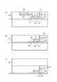
(第2の実施例)
本発明による積層型半導体素子の構造の第2の実施例を図5に示す。第2の実施例は、第1の実施例と比較して、第3層半導体回路30のMOSトランジスタ301の位置が異なっている。(Second embodiment)
FIG. 5 shows a second embodiment of the structure of the stacked semiconductor device according to the present invention. The second embodiment differs from the first embodiment in the position of the
第1の実施例では、第3層半導体回路30のMOSトランジスタ301の位置と、層間配線の位置が離れていたため、第3層半導体回路内において、高濃度拡散層305Bと第1配線351とを用いて、層間配線とMOSトランジスタ301のソース/ドレイン領域305とを接続していた。これは、層内配線(水平方向の配線)においては、金属配線が低抵抗であり、容易に形成可能だからである。 In the first embodiment, since the position of the
図5で示す第2の実施例は、第3層半導体回路30のMOSトランジスタ301の位置を変更した場合であり、層間配線510の位置がMOSトランジスタ301のソース/ドレイン領域305の直下に設計されている。このときは、層内配線(水平方向の配線)としての第1の配線351を用いる必要はなく、MOSトランジスタ301のソース/ドレイン領域305に接続する接合電極354を形成し、層間配線を構成する接合電極354を介してMOSトランジスタ301のソース/ドレイン領域305に接続することができる。 The second embodiment shown in FIG. 5 is a case where the position of the
すなわち、第3層のMOSトランジスタ301のソース/ドレイン領域305が、接合電極354、第2層半導体回路20の第2の配線252、第1の配線251、高濃度拡散層205B、接合電極253、第1層半導体回路10の第2の配線152、第1の配線151の経路で、第1層半導体回路10のMOSトランジスタ101のソース/ドレイン領域105と接続される。これにより、第1の実施例よりも接続抵抗を低減できる。 That is, the source /
(第3の実施例)
本発明による積層型半導体素子の構造の第3の実施例を図6に示す。第3の実施例は、層間配線に若干の変更を加えて、他の層における回路構成を容易にしたものである。(Third embodiment)
FIG. 6 shows a third embodiment of the structure of the stacked semiconductor device according to the present invention. In the third embodiment, a slight change is made to the interlayer wiring to facilitate the circuit configuration in the other layers.
第1の実施例、第2の実施例においては、層間配線510は、第2層半導体回路20の第2の配線252、第1の配線251、高濃度拡散層205B、及び接合電極253のように、各導電部材が直線上に配置されており、これにより、層間配線510の断面積をコンタクトホール形成限界の小さいものにすることができた。しかしながら、他方で、第3層半導体回路30で、水平方向の層内配線を必要としたり、また、MOSトランジスタ301のレイアウトの工夫を必要とする場合があった。 In the first embodiment and the second embodiment, the
図6に示す第3の実施例は、層間配線を構成する第2の配線252を水平方向に拡張し、第3層半導体回路30のMOSトランジスタ301の直下まで伸ばしたものである。この場合、層間配線を平面視したときの断面積は大きくなるが、第2の配線252は第2層半導体回路20のMOSトランジスタ201の上部に張り出すものであって、実質的には、MOSトランジスタ201に多層化した配線と同様であり、平面的スペースを無駄にするものではない。 In the third embodiment shown in FIG. 6, the
また、この構造の製造にあたっては、第2層半導体回路20の形成時に、第2の配線252のレイアウトを僅かに変更するのみであり、工程的な追加は一切発生しない。このように、第2の配線252、さらに必要あれば第1の配線251のレイアウトに変更を加えて、柔軟性のある層間配線を形成することができる。 In manufacturing this structure, only the layout of the
本発明を諸図面や実施例に基づき説明してきたが、当業者であれば本開示に基づき種々の変形や修正を行うことが容易であることに注意されたい。従って、これらの変形や修正は本発明の範囲に含まれることに留意されたい。例えば、各手段、各ステップ等に含まれる機能等は論理的に矛盾しないように再配置可能であり、複数の手段やステップ等を1つに組み合わせたり、或いは分割したりすることが可能である。 Although the present invention has been described based on the drawings and examples, it should be noted that those skilled in the art can easily make various modifications and corrections based on the present disclosure. Therefore, it should be noted that these variations and modifications are included in the scope of the present invention. For example, the functions included in each means, each step, etc. can be rearranged so that there is no logical contradiction, and a plurality of means, steps, etc. can be combined or divided into one. .
10 第1層半導体回路
20 第2層半導体回路
30 第3層半導体回路
40 第4層半導体回路
100 支持基板
101 MOSトランジスタ
102 活性層
103 ゲート絶縁膜
104 ゲート電極
105 ソース/ドレイン領域
110 埋め込み絶縁層
120 単結晶シリコン層
130 第1の絶縁層
151 第1の配線
152 第2の配線
200 仮基板
201 MOSトランジスタ
202 活性層
203 ゲート絶縁膜
204 ゲート電極
205 ソース/ドレイン領域
205B 高濃度拡散層(不純物拡散半導体層)
210 埋め込み絶縁層
220 単結晶シリコン層
230 第2の絶縁層
251 第1の配線
252 第2の配線
253 接合電極
301 MOSトランジスタ
305 ソース/ドレイン領域
305B 高濃度拡散層(不純物拡散半導体層)
310 埋め込み絶縁層
330 第3の絶縁層
351 第1の配線
352 第2の配線
353 第3の配線
354 接合電極
410 埋め込み絶縁層
430 第4の絶縁層
501 貫通ビアホール
502 金属層
510 層間配線
520 層間配線DESCRIPTION OF
210 buried insulating
310 buried insulating
Claims (9)
Translated fromJapanese少なくとも一つの前記単層半導体回路は、前記単層半導体回路の第1及び第2の主面の間を貫通する層間配線を備え、前記層間配線は、不純物が導入された半導体層と、前記第1及び第2の主面に露出する前記半導体層よりも高導電性の材料とを備えることを特徴とする積層型半導体素子。A laminated semiconductor element formed by laminating a plurality of single-layer semiconductor circuits,
At least one of the single-layer semiconductor circuits includes an interlayer wiring penetrating between the first and second main surfaces of the single-layer semiconductor circuit, and the interlayer wiring includes a semiconductor layer into which an impurity is introduced; A stacked semiconductor element comprising: a material having higher conductivity than the semiconductor layer exposed on the first and second main surfaces.
少なくとも一つの前記単層半導体回路の半導体層に不純物を導入して不純物拡散半導体層を形成する工程と、
前記単層半導体回路の第1の主面側から、前記不純物拡散半導体層に接続する前記不純物拡散半導体層よりも高導電性の材料からなる配線を形成する工程と、
前記単層半導体回路の第2の主面側から、前記不純物拡散半導体層に接続する前記不純物拡散半導体層よりも高導電性の材料からなる配線を形成する工程と、を備え、
前記単層半導体回路の第1及び第2の主面の間を貫通する層間配線を形成することを特徴とする積層型半導体素子の製造方法。A method for manufacturing a stacked semiconductor element in which a plurality of single-layer semiconductor circuits are stacked,
Introducing an impurity into a semiconductor layer of at least one single-layer semiconductor circuit to form an impurity diffusion semiconductor layer;
Forming a wiring made of a material having higher conductivity than the impurity diffusion semiconductor layer connected to the impurity diffusion semiconductor layer from the first main surface side of the single-layer semiconductor circuit;
Forming a wiring made of a material having higher conductivity than the impurity diffusion semiconductor layer connected to the impurity diffusion semiconductor layer from the second main surface side of the single-layer semiconductor circuit,
An interlayer wiring penetrating between the first and second main surfaces of the single-layer semiconductor circuit is formed.
Priority Applications (1)
| Application Number | Priority Date | Filing Date | Title |
|---|---|---|---|
| JP2014186694AJP2016062903A (en) | 2014-09-12 | 2014-09-12 | Laminated semiconductor element and manufacturing method thereof |
Applications Claiming Priority (1)
| Application Number | Priority Date | Filing Date | Title |
|---|---|---|---|
| JP2014186694AJP2016062903A (en) | 2014-09-12 | 2014-09-12 | Laminated semiconductor element and manufacturing method thereof |
Publications (1)
| Publication Number | Publication Date |
|---|---|
| JP2016062903Atrue JP2016062903A (en) | 2016-04-25 |
Family
ID=55798084
Family Applications (1)
| Application Number | Title | Priority Date | Filing Date |
|---|---|---|---|
| JP2014186694APendingJP2016062903A (en) | 2014-09-12 | 2014-09-12 | Laminated semiconductor element and manufacturing method thereof |
Country Status (1)
| Country | Link |
|---|---|
| JP (1) | JP2016062903A (en) |
Cited By (1)
| Publication number | Priority date | Publication date | Assignee | Title |
|---|---|---|---|---|
| JP2020120046A (en)* | 2019-01-25 | 2020-08-06 | 日本放送協会 | Laminated semiconductor device and method for manufacturing the same |
Citations (4)
| Publication number | Priority date | Publication date | Assignee | Title |
|---|---|---|---|---|
| JPS4879982A (en)* | 1972-01-27 | 1973-10-26 | ||
| JPS6418248A (en)* | 1987-07-13 | 1989-01-23 | Nec Corp | Manufacture of semiconductor device |
| JP2009076879A (en)* | 2007-08-24 | 2009-04-09 | Semiconductor Energy Lab Co Ltd | Semiconductor device |
| US20120119310A1 (en)* | 2010-11-11 | 2012-05-17 | International Business Machines Corporation | Structure and method to fabricate a body contact |
- 2014
- 2014-09-12JPJP2014186694Apatent/JP2016062903A/enactivePending
Patent Citations (4)
| Publication number | Priority date | Publication date | Assignee | Title |
|---|---|---|---|---|
| JPS4879982A (en)* | 1972-01-27 | 1973-10-26 | ||
| JPS6418248A (en)* | 1987-07-13 | 1989-01-23 | Nec Corp | Manufacture of semiconductor device |
| JP2009076879A (en)* | 2007-08-24 | 2009-04-09 | Semiconductor Energy Lab Co Ltd | Semiconductor device |
| US20120119310A1 (en)* | 2010-11-11 | 2012-05-17 | International Business Machines Corporation | Structure and method to fabricate a body contact |
Cited By (1)
| Publication number | Priority date | Publication date | Assignee | Title |
|---|---|---|---|---|
| JP2020120046A (en)* | 2019-01-25 | 2020-08-06 | 日本放送協会 | Laminated semiconductor device and method for manufacturing the same |
Similar Documents
| Publication | Publication Date | Title |
|---|---|---|
| CN111415941B (en) | Multi-layer stacked three-dimensional memory device | |
| TWI427700B (en) | Method for manufacturing semiconductor device with three-dimensional laminated structure | |
| CN102738168B (en) | Semiconductor device and its manufacture method | |
| CN111446207B (en) | Method of forming three-dimensional integrated wiring structure and semiconductor structure thereof | |
| JP4869664B2 (en) | Manufacturing method of semiconductor device | |
| TWI540725B (en) | Semiconductor device and method of manufacturing the same | |
| US10950543B2 (en) | Semiconductor device and method of manufacturing the same | |
| TWI566362B (en) | Semiconductor device and method of manufacturing the same | |
| JP2013077711A (en) | Semiconductor device and manufacturing method of semiconductor device | |
| CN110088889B (en) | Method for forming three-dimensional integrated wiring structure and semiconductor structure thereof | |
| TW200539242A (en) | Semiconductor device and semiconductor system | |
| US8384207B2 (en) | Semiconductor integrated circuit device having insulated through wires | |
| JP4383274B2 (en) | Semiconductor device and semiconductor wafer manufacturing method | |
| TWI379382B (en) | ||
| US20110266677A1 (en) | Semiconductor structure and manufacturing method of the same | |
| US20040026762A1 (en) | Semiconductor device | |
| JP5271562B2 (en) | Semiconductor device and manufacturing method of semiconductor device | |
| CN110088890A (en) | Form the method and its semiconductor structure of three-dimensionally integrated wire structures | |
| JP2001320052A (en) | Semiconductor device and semiconductor integrated circuit | |
| JP2016062903A (en) | Laminated semiconductor element and manufacturing method thereof | |
| JP5271561B2 (en) | Semiconductor device and manufacturing method of semiconductor device | |
| JP4372136B2 (en) | Manufacturing method of semiconductor device | |
| JP2014138178A (en) | Electronic device, manufacturing method of electronic device, substrate structure, and manufacturing method of substrate structure | |
| JP6072858B2 (en) | Manufacturing method of semiconductor device | |
| WO2021031419A1 (en) | First wafer and formation method therefor, and wafer stack structure |
Legal Events
| Date | Code | Title | Description |
|---|---|---|---|
| A621 | Written request for application examination | Free format text:JAPANESE INTERMEDIATE CODE: A621 Effective date:20170731 | |
| A977 | Report on retrieval | Free format text:JAPANESE INTERMEDIATE CODE: A971007 Effective date:20180308 | |
| A131 | Notification of reasons for refusal | Free format text:JAPANESE INTERMEDIATE CODE: A131 Effective date:20180313 | |
| A02 | Decision of refusal | Free format text:JAPANESE INTERMEDIATE CODE: A02 Effective date:20180911 |