JP2016059751A - Display device, electronic device, control method thereof, and control program - Google Patents
Display device, electronic device, control method thereof, and control programDownload PDFInfo
- Publication number
- JP2016059751A JP2016059751AJP2014192405AJP2014192405AJP2016059751AJP 2016059751 AJP2016059751 AJP 2016059751AJP 2014192405 AJP2014192405 AJP 2014192405AJP 2014192405 AJP2014192405 AJP 2014192405AJP 2016059751 AJP2016059751 AJP 2016059751A
- Authority
- JP
- Japan
- Prior art keywords
- display
- display panel
- image
- arithmetic circuit
- circuit unit
- Prior art date
- Legal status (The legal status is an assumption and is not a legal conclusion. Google has not performed a legal analysis and makes no representation as to the accuracy of the status listed.)
- Pending
Links
Images


Classifications
- G—PHYSICS
- G06—COMPUTING OR CALCULATING; COUNTING
- G06F—ELECTRIC DIGITAL DATA PROCESSING
- G06F1/00—Details not covered by groups G06F3/00 - G06F13/00 and G06F21/00
- G06F1/16—Constructional details or arrangements
- G06F1/1613—Constructional details or arrangements for portable computers
- G06F1/163—Wearable computers, e.g. on a belt
- G—PHYSICS
- G06—COMPUTING OR CALCULATING; COUNTING
- G06F—ELECTRIC DIGITAL DATA PROCESSING
- G06F3/00—Input arrangements for transferring data to be processed into a form capable of being handled by the computer; Output arrangements for transferring data from processing unit to output unit, e.g. interface arrangements
- G06F3/002—Specific input/output arrangements not covered by G06F3/01 - G06F3/16
- G—PHYSICS
- G06—COMPUTING OR CALCULATING; COUNTING
- G06F—ELECTRIC DIGITAL DATA PROCESSING
- G06F1/00—Details not covered by groups G06F3/00 - G06F13/00 and G06F21/00
- G06F1/16—Constructional details or arrangements
- G06F1/1613—Constructional details or arrangements for portable computers
- G06F1/1633—Constructional details or arrangements of portable computers not specific to the type of enclosures covered by groups G06F1/1615 - G06F1/1626
- G06F1/1684—Constructional details or arrangements related to integrated I/O peripherals not covered by groups G06F1/1635 - G06F1/1675
- G06F1/1694—Constructional details or arrangements related to integrated I/O peripherals not covered by groups G06F1/1635 - G06F1/1675 the I/O peripheral being a single or a set of motion sensors for pointer control or gesture input obtained by sensing movements of the portable computer
- G—PHYSICS
- G06—COMPUTING OR CALCULATING; COUNTING
- G06F—ELECTRIC DIGITAL DATA PROCESSING
- G06F1/00—Details not covered by groups G06F3/00 - G06F13/00 and G06F21/00
- G06F1/26—Power supply means, e.g. regulation thereof
- G06F1/32—Means for saving power
- G06F1/3203—Power management, i.e. event-based initiation of a power-saving mode
- G06F1/3206—Monitoring of events, devices or parameters that trigger a change in power modality
- G06F1/3215—Monitoring of peripheral devices
- G—PHYSICS
- G06—COMPUTING OR CALCULATING; COUNTING
- G06F—ELECTRIC DIGITAL DATA PROCESSING
- G06F1/00—Details not covered by groups G06F3/00 - G06F13/00 and G06F21/00
- G06F1/26—Power supply means, e.g. regulation thereof
- G06F1/32—Means for saving power
- G06F1/3203—Power management, i.e. event-based initiation of a power-saving mode
- G06F1/3206—Monitoring of events, devices or parameters that trigger a change in power modality
- G06F1/3231—Monitoring the presence, absence or movement of users
- G—PHYSICS
- G06—COMPUTING OR CALCULATING; COUNTING
- G06F—ELECTRIC DIGITAL DATA PROCESSING
- G06F1/00—Details not covered by groups G06F3/00 - G06F13/00 and G06F21/00
- G06F1/26—Power supply means, e.g. regulation thereof
- G06F1/32—Means for saving power
- G06F1/3203—Power management, i.e. event-based initiation of a power-saving mode
- G06F1/3234—Power saving characterised by the action undertaken
- G06F1/325—Power saving in peripheral device
- G06F1/3265—Power saving in display device
- G—PHYSICS
- G06—COMPUTING OR CALCULATING; COUNTING
- G06F—ELECTRIC DIGITAL DATA PROCESSING
- G06F1/00—Details not covered by groups G06F3/00 - G06F13/00 and G06F21/00
- G06F1/26—Power supply means, e.g. regulation thereof
- G06F1/32—Means for saving power
- G06F1/3203—Power management, i.e. event-based initiation of a power-saving mode
- G06F1/3234—Power saving characterised by the action undertaken
- G06F1/3293—Power saving characterised by the action undertaken by switching to a less power-consuming processor, e.g. sub-CPU
- G—PHYSICS
- G06—COMPUTING OR CALCULATING; COUNTING
- G06F—ELECTRIC DIGITAL DATA PROCESSING
- G06F3/00—Input arrangements for transferring data to be processed into a form capable of being handled by the computer; Output arrangements for transferring data from processing unit to output unit, e.g. interface arrangements
- G06F3/01—Input arrangements or combined input and output arrangements for interaction between user and computer
- G06F3/017—Gesture based interaction, e.g. based on a set of recognized hand gestures
- G—PHYSICS
- G06—COMPUTING OR CALCULATING; COUNTING
- G06F—ELECTRIC DIGITAL DATA PROCESSING
- G06F3/00—Input arrangements for transferring data to be processed into a form capable of being handled by the computer; Output arrangements for transferring data from processing unit to output unit, e.g. interface arrangements
- G06F3/14—Digital output to display device ; Cooperation and interconnection of the display device with other functional units
- G06F3/1423—Digital output to display device ; Cooperation and interconnection of the display device with other functional units controlling a plurality of local displays, e.g. CRT and flat panel display
- G06F3/1438—Digital output to display device ; Cooperation and interconnection of the display device with other functional units controlling a plurality of local displays, e.g. CRT and flat panel display using more than one graphics controller
- G—PHYSICS
- G06—COMPUTING OR CALCULATING; COUNTING
- G06F—ELECTRIC DIGITAL DATA PROCESSING
- G06F3/00—Input arrangements for transferring data to be processed into a form capable of being handled by the computer; Output arrangements for transferring data from processing unit to output unit, e.g. interface arrangements
- G06F3/16—Sound input; Sound output
- G—PHYSICS
- G09—EDUCATION; CRYPTOGRAPHY; DISPLAY; ADVERTISING; SEALS
- G09G—ARRANGEMENTS OR CIRCUITS FOR CONTROL OF INDICATING DEVICES USING STATIC MEANS TO PRESENT VARIABLE INFORMATION
- G09G3/00—Control arrangements or circuits, of interest only in connection with visual indicators other than cathode-ray tubes
- G09G3/20—Control arrangements or circuits, of interest only in connection with visual indicators other than cathode-ray tubes for presentation of an assembly of a number of characters, e.g. a page, by composing the assembly by combination of individual elements arranged in a matrix no fixed position being assigned to or needed to be assigned to the individual characters or partial characters
- G09G3/34—Control arrangements or circuits, of interest only in connection with visual indicators other than cathode-ray tubes for presentation of an assembly of a number of characters, e.g. a page, by composing the assembly by combination of individual elements arranged in a matrix no fixed position being assigned to or needed to be assigned to the individual characters or partial characters by control of light from an independent source
- G09G3/3406—Control of illumination source
- G—PHYSICS
- G09—EDUCATION; CRYPTOGRAPHY; DISPLAY; ADVERTISING; SEALS
- G09G—ARRANGEMENTS OR CIRCUITS FOR CONTROL OF INDICATING DEVICES USING STATIC MEANS TO PRESENT VARIABLE INFORMATION
- G09G3/00—Control arrangements or circuits, of interest only in connection with visual indicators other than cathode-ray tubes
- G09G3/20—Control arrangements or circuits, of interest only in connection with visual indicators other than cathode-ray tubes for presentation of an assembly of a number of characters, e.g. a page, by composing the assembly by combination of individual elements arranged in a matrix no fixed position being assigned to or needed to be assigned to the individual characters or partial characters
- G09G3/34—Control arrangements or circuits, of interest only in connection with visual indicators other than cathode-ray tubes for presentation of an assembly of a number of characters, e.g. a page, by composing the assembly by combination of individual elements arranged in a matrix no fixed position being assigned to or needed to be assigned to the individual characters or partial characters by control of light from an independent source
- G09G3/36—Control arrangements or circuits, of interest only in connection with visual indicators other than cathode-ray tubes for presentation of an assembly of a number of characters, e.g. a page, by composing the assembly by combination of individual elements arranged in a matrix no fixed position being assigned to or needed to be assigned to the individual characters or partial characters by control of light from an independent source using liquid crystals
- G—PHYSICS
- G11—INFORMATION STORAGE
- G11B—INFORMATION STORAGE BASED ON RELATIVE MOVEMENT BETWEEN RECORD CARRIER AND TRANSDUCER
- G11B20/00—Signal processing not specific to the method of recording or reproducing; Circuits therefor
- G11B20/10—Digital recording or reproducing
- G11B20/10527—Audio or video recording; Data buffering arrangements
- H—ELECTRICITY
- H04—ELECTRIC COMMUNICATION TECHNIQUE
- H04M—TELEPHONIC COMMUNICATION
- H04M1/00—Substation equipment, e.g. for use by subscribers
- H04M1/72—Mobile telephones; Cordless telephones, i.e. devices for establishing wireless links to base stations without route selection
- H04M1/724—User interfaces specially adapted for cordless or mobile telephones
- H04M1/72403—User interfaces specially adapted for cordless or mobile telephones with means for local support of applications that increase the functionality
- H04M1/72409—User interfaces specially adapted for cordless or mobile telephones with means for local support of applications that increase the functionality by interfacing with external accessories
- H04M1/724094—Interfacing with a device worn on the user's body to provide access to telephonic functionalities, e.g. accepting a call, reading or composing a message
- H—ELECTRICITY
- H04—ELECTRIC COMMUNICATION TECHNIQUE
- H04M—TELEPHONIC COMMUNICATION
- H04M1/00—Substation equipment, e.g. for use by subscribers
- H04M1/72—Mobile telephones; Cordless telephones, i.e. devices for establishing wireless links to base stations without route selection
- H04M1/724—User interfaces specially adapted for cordless or mobile telephones
- H04M1/72403—User interfaces specially adapted for cordless or mobile telephones with means for local support of applications that increase the functionality
- H04M1/72442—User interfaces specially adapted for cordless or mobile telephones with means for local support of applications that increase the functionality for playing music files
- G—PHYSICS
- G09—EDUCATION; CRYPTOGRAPHY; DISPLAY; ADVERTISING; SEALS
- G09G—ARRANGEMENTS OR CIRCUITS FOR CONTROL OF INDICATING DEVICES USING STATIC MEANS TO PRESENT VARIABLE INFORMATION
- G09G2300/00—Aspects of the constitution of display devices
- G09G2300/02—Composition of display devices
- G09G2300/023—Display panel composed of stacked panels
- G—PHYSICS
- G09—EDUCATION; CRYPTOGRAPHY; DISPLAY; ADVERTISING; SEALS
- G09G—ARRANGEMENTS OR CIRCUITS FOR CONTROL OF INDICATING DEVICES USING STATIC MEANS TO PRESENT VARIABLE INFORMATION
- G09G2300/00—Aspects of the constitution of display devices
- G09G2300/04—Structural and physical details of display devices
- G09G2300/0439—Pixel structures
- G09G2300/0456—Pixel structures with a reflective area and a transmissive area combined in one pixel, such as in transflectance pixels
- G—PHYSICS
- G09—EDUCATION; CRYPTOGRAPHY; DISPLAY; ADVERTISING; SEALS
- G09G—ARRANGEMENTS OR CIRCUITS FOR CONTROL OF INDICATING DEVICES USING STATIC MEANS TO PRESENT VARIABLE INFORMATION
- G09G2330/00—Aspects of power supply; Aspects of display protection and defect management
- G09G2330/02—Details of power systems and of start or stop of display operation
- G09G2330/021—Power management, e.g. power saving
- G09G2330/022—Power management, e.g. power saving in absence of operation, e.g. no data being entered during a predetermined time
- G—PHYSICS
- G09—EDUCATION; CRYPTOGRAPHY; DISPLAY; ADVERTISING; SEALS
- G09G—ARRANGEMENTS OR CIRCUITS FOR CONTROL OF INDICATING DEVICES USING STATIC MEANS TO PRESENT VARIABLE INFORMATION
- G09G2340/00—Aspects of display data processing
- G09G2340/04—Changes in size, position or resolution of an image
- G09G2340/0407—Resolution change, inclusive of the use of different resolutions for different screen areas
- G09G2340/0428—Gradation resolution change
- G—PHYSICS
- G09—EDUCATION; CRYPTOGRAPHY; DISPLAY; ADVERTISING; SEALS
- G09G—ARRANGEMENTS OR CIRCUITS FOR CONTROL OF INDICATING DEVICES USING STATIC MEANS TO PRESENT VARIABLE INFORMATION
- G09G3/00—Control arrangements or circuits, of interest only in connection with visual indicators other than cathode-ray tubes
- G09G3/20—Control arrangements or circuits, of interest only in connection with visual indicators other than cathode-ray tubes for presentation of an assembly of a number of characters, e.g. a page, by composing the assembly by combination of individual elements arranged in a matrix no fixed position being assigned to or needed to be assigned to the individual characters or partial characters
- G09G3/2003—Display of colours
- H—ELECTRICITY
- H04—ELECTRIC COMMUNICATION TECHNIQUE
- H04M—TELEPHONIC COMMUNICATION
- H04M1/00—Substation equipment, e.g. for use by subscribers
- H04M1/72—Mobile telephones; Cordless telephones, i.e. devices for establishing wireless links to base stations without route selection
- H04M1/724—User interfaces specially adapted for cordless or mobile telephones
- H04M1/72403—User interfaces specially adapted for cordless or mobile telephones with means for local support of applications that increase the functionality
- H04M1/72409—User interfaces specially adapted for cordless or mobile telephones with means for local support of applications that increase the functionality by interfacing with external accessories
- H04M1/72412—User interfaces specially adapted for cordless or mobile telephones with means for local support of applications that increase the functionality by interfacing with external accessories using two-way short-range wireless interfaces
- Y—GENERAL TAGGING OF NEW TECHNOLOGICAL DEVELOPMENTS; GENERAL TAGGING OF CROSS-SECTIONAL TECHNOLOGIES SPANNING OVER SEVERAL SECTIONS OF THE IPC; TECHNICAL SUBJECTS COVERED BY FORMER USPC CROSS-REFERENCE ART COLLECTIONS [XRACs] AND DIGESTS
- Y02—TECHNOLOGIES OR APPLICATIONS FOR MITIGATION OR ADAPTATION AGAINST CLIMATE CHANGE
- Y02D—CLIMATE CHANGE MITIGATION TECHNOLOGIES IN INFORMATION AND COMMUNICATION TECHNOLOGIES [ICT], I.E. INFORMATION AND COMMUNICATION TECHNOLOGIES AIMING AT THE REDUCTION OF THEIR OWN ENERGY USE
- Y02D10/00—Energy efficient computing, e.g. low power processors, power management or thermal management
- Y—GENERAL TAGGING OF NEW TECHNOLOGICAL DEVELOPMENTS; GENERAL TAGGING OF CROSS-SECTIONAL TECHNOLOGIES SPANNING OVER SEVERAL SECTIONS OF THE IPC; TECHNICAL SUBJECTS COVERED BY FORMER USPC CROSS-REFERENCE ART COLLECTIONS [XRACs] AND DIGESTS
- Y02—TECHNOLOGIES OR APPLICATIONS FOR MITIGATION OR ADAPTATION AGAINST CLIMATE CHANGE
- Y02D—CLIMATE CHANGE MITIGATION TECHNOLOGIES IN INFORMATION AND COMMUNICATION TECHNOLOGIES [ICT], I.E. INFORMATION AND COMMUNICATION TECHNOLOGIES AIMING AT THE REDUCTION OF THEIR OWN ENERGY USE
- Y02D30/00—Reducing energy consumption in communication networks
- Y02D30/70—Reducing energy consumption in communication networks in wireless communication networks
Landscapes
- Engineering & Computer Science (AREA)
- Theoretical Computer Science (AREA)
- Physics & Mathematics (AREA)
- General Physics & Mathematics (AREA)
- General Engineering & Computer Science (AREA)
- Computer Hardware Design (AREA)
- Human Computer Interaction (AREA)
- Signal Processing (AREA)
- Computer Networks & Wireless Communication (AREA)
- Multimedia (AREA)
- Computer Graphics (AREA)
- Crystallography & Structural Chemistry (AREA)
- Chemical & Material Sciences (AREA)
- Health & Medical Sciences (AREA)
- Audiology, Speech & Language Pathology (AREA)
- General Health & Medical Sciences (AREA)
- Control Of Indicators Other Than Cathode Ray Tubes (AREA)
- Controls And Circuits For Display Device (AREA)
- Liquid Crystal Display Device Control (AREA)
Abstract
Translated fromJapaneseDescription
Translated fromJapanese本発明は、利用者(ユーザ)が身体に装着する装着型や携帯型の電子機器に関し、特に、各種の情報を表示する表示装置を備えた電子機器及びその制御方法、制御プログラムに関する。 The present invention relates to a wearable or portable electronic device that a user (user) wears on the body, and more particularly to an electronic device including a display device that displays various types of information, a control method thereof, and a control program.
近年、人体に装着して、ランニングやサイクリング、スイミング、トレッキング等の運動時や、日常生活における各種のデータを記録して分析するための種々の製品が開発され、市販されている。また、携帯電話機やスマートフォン(高機能型携帯電話機)、タブレット端末等の携帯型の電子機器も広く普及している。このような機器の大半は、利用者に各種の情報を提供するための表示装置を備えている。 2. Description of the Related Art In recent years, various products have been developed and marketed for wearing on the human body and recording and analyzing various data during exercise such as running, cycling, swimming, trekking, and daily life. Portable electronic devices such as mobile phones, smartphones (high-function mobile phones), and tablet terminals are also widely used. Most of such devices are equipped with a display device for providing various information to the user.
例えば特許文献1には、利用者の身体に装着し、運動時に収集したり、分析したりした運動データ等を、表示装置に表示して利用者に提供する機能を備えた、いわゆるスポーツウォッチが開示されている。 For example,
上述した特許文献1等に開示されたスポーツウォッチをはじめ、近年の装着型や携帯型の電子機器においては、例えば、加速度センサやジャイロセンサ(角速度センサ)、GPS(Global Positioning System;全地球測位システム)による測位機能等の、種々のセンサ類を備えている。これらのセンサ類は、電子機器の携帯時や使用時には、常時センシング動作を行うように設定されて、利用者の運動状態や移動経路をログデータとして記録したり、現在位置を検出したりしているほか、表示装置を介して当該情報を利用者に提供しているため、常時電力を消費している。 In recent sports-type and portable electronic devices such as the sports watch disclosed in
特に、近年の装着型や携帯型の電子機器においては、利用者への各種情報の良好な伝達性や視認性、見栄え等の観点から、カラー表示による情報提供や様々な視覚効果(例えば表示画像のトランジションエフェクト等)が求められるようになってきている。このようなカラー表示や視覚効果を適用することにより、利用者が運動中や移動中であっても、直感的に理解しやすく、かつ、豊かな色彩表現や様々な視覚効果を用いた表示形態(以下、便宜的に「リッチなカラー表示」と記す)で情報を提供することができる。しかしながら、一般に、リッチなカラー表示による情報提供においては、デジタル時計等に適用される、セグメントや簡易な図形を組み合わせた画面変化の少ないモノクロ表示に比較して、表示駆動用のプロセッサや表示パネル、バックライト等における消費電力が著しく大きくなる。 In particular, in recent wearable and portable electronic devices, information display by color display and various visual effects (for example, display images) from the viewpoints of good transmission, visibility, and appearance of various information to users. Transition effects, etc.) have been demanded. By applying such color display and visual effects, it is easy to understand intuitively even if the user is exercising or moving, and a display format that uses rich color expressions and various visual effects (Hereinafter referred to as “rich color display” for convenience) can provide information. However, in general, in providing information by a rich color display, a display driving processor or display panel, which is applied to a digital clock or the like, compared to a monochrome display with a small screen change combining segments and simple figures, The power consumption in the backlight or the like is significantly increased.
そのため、バッテリにより駆動するスポーツウォッチ等の装着型や携帯型の電子機器において、利用者の運動等に関わる種々のログデータを記録しながら、各種の情報をリッチなカラー表示により提供する場合、電子機器の駆動時間が非常に短くなってしまうという問題を有していた。 For this reason, in a wearable or portable electronic device such as a sports watch driven by a battery, various types of information are provided by rich color display while recording various log data related to user's exercises, etc. There has been a problem that the drive time of the device becomes very short.
そこで、本発明は、上述した問題点に鑑みて、各種の情報をより視認性が高くリッチなカラー表示で提供することができ、かつ、電力の消費を抑制して駆動時間を改善することができる表示装置、並びに、当該表示装置を備えた電子機器及びその制御方法、制御プログラムを提供することを目的とする。 Accordingly, in view of the above-described problems, the present invention can provide various types of information in a highly visible and rich color display, and can reduce power consumption and improve driving time. It is an object to provide a display device that can be used, an electronic device including the display device, a control method thereof, and a control program.
本発明は、
表示装置であって、
第1の表示領域を有する第1の表示パネルと、
前記第1の表示パネルの表示状態を制御する第1の演算回路部と、
第2の表示領域を有する第2の表示パネルと、
前記第1の演算回路部と連携して、前記第2の表示パネルの表示状態を制御する第2の演算回路部と、
前記表示装置の空間的な動きを検知する検知部と、
を有し、
前記第1の演算回路部及び前記第2の演算回路部の少なくともいずれか一方は、前記検知部による検知の結果に応じて、前記第1の表示パネルと前記第2の表示パネルとによる表示画像の表示形態を切り替えることを特徴とする。The present invention
A display device,
A first display panel having a first display area;
A first arithmetic circuit unit for controlling a display state of the first display panel;
A second display panel having a second display area;
A second arithmetic circuit unit for controlling a display state of the second display panel in cooperation with the first arithmetic circuit unit;
A detection unit for detecting a spatial movement of the display device;
Have
At least one of the first arithmetic circuit unit and the second arithmetic circuit unit is a display image by the first display panel and the second display panel according to a detection result by the detection unit. The display form is switched.
本発明に係る電子機器は、
第1の表示領域を有する第1の表示パネルと、前記第1の表示パネルの表示状態を制御する第1の演算回路部と、第2の表示領域を有する第2の表示パネルと、前記第1の演算回路部と連携して、前記第2の表示パネルの表示状態を制御する第2の演算回路部と、を有する表示装置と、
前記表示装置の空間的な動きを検知する検知部と、
を備え、
前記表示装置の前記第1の演算回路部及び前記第2の演算回路部の少なくともいずれか一方は、前記検知部による検知の結果に応じて、前記第1の表示パネルと前記第2の表示パネルとによる表示画像の表示形態を切り替えることを特徴とする。The electronic device according to the present invention is
A first display panel having a first display area; a first arithmetic circuit unit for controlling a display state of the first display panel; a second display panel having a second display area; A display device having a second arithmetic circuit unit that controls a display state of the second display panel in cooperation with one arithmetic circuit unit;
A detection unit for detecting a spatial movement of the display device;
With
At least one of the first arithmetic circuit unit and the second arithmetic circuit unit of the display device includes the first display panel and the second display panel according to a detection result by the detection unit. And the display form of the display image is switched.
本発明に係る電子機器の制御方法は、
第1の表示領域を有する第1の表示パネルと、利用者の視野側から見て前記第1の表示領域と少なくとも一部が互いに重なり合うように配置された第2の表示領域を有する第2の表示パネルと、を有する表示部に、前記第1の表示パネルの表示状態と前記第2の表示パネルの表示状態とを組み合わせた表示画像を表示し、
前記第1の表示パネル及び前記第2の表示パネルの空間的な動きを検知し、
前記検知の結果に応じて、前記第1の表示パネルと前記第2の表示パネルとによる前記表示画像の表示形態を切り替えることを特徴とする。An electronic device control method according to the present invention includes:
A first display panel having a first display area, and a second display area having a second display area arranged so that at least a part of the first display area and the first display area overlap each other when viewed from the user's field of view Displaying a display image that combines the display state of the first display panel and the display state of the second display panel on a display unit having a display panel;
Detecting spatial movements of the first display panel and the second display panel;
The display form of the display image is switched between the first display panel and the second display panel according to the detection result.
本発明に係る電子機器の制御プログラムは、
コンピュータに、
第1の表示領域を有する第1の表示パネルと、利用者の視野側から見て前記第1の表示領域と少なくとも一部が互いに重なり合うように配置された第2の表示領域を有する第2の表示パネルと、を有する表示部に、前記第1の表示パネルの表示状態と前記第2の表示パネルの表示状態とを組み合わせた表示画像を表示させ、
前記第1の表示パネル及び前記第2の表示パネルの空間的な動きを検知させ、
前記検知の結果に応じて、前記第1の表示パネルと前記第2の表示パネルとによる前記表示画像の表示形態を切り替えさせることを特徴とする。An electronic device control program according to the present invention includes:
On the computer,
A first display panel having a first display area, and a second display area having a second display area arranged so that at least a part of the first display area and the first display area overlap each other when viewed from the user's field of view A display unit having a display panel, and displaying a display image combining the display state of the first display panel and the display state of the second display panel,
Detecting spatial movements of the first display panel and the second display panel;
The display form of the display image by the first display panel and the second display panel is switched according to the detection result.
本発明によれば、表示装置を備えた携帯型の電子機器において、各種の情報をより視認性が高くリッチなカラー表示で提供することができ、かつ、電力の消費を抑制して駆動時間を改善することができる。 According to the present invention, in a portable electronic device equipped with a display device, various types of information can be provided in a highly visible and rich color display, and the driving time can be reduced while suppressing power consumption. Can be improved.
以下に、本発明に係る表示装置、当該表示装置を備えた電子機器及びその制御方法、制御プログラムについて、実施形態を示して詳しく説明する。
<表示装置、電子機器>
図1は、本発明に係る表示装置を備えた電子機器の一実施形態を示す概略構成図である。図1(a)〜(c)は、本実施形態に係る電子機器の複数の具体例を示す概略斜視図であり、図1(d)は、本実施形態に係る電子機器に適用される表示装置の構成例を示す概略斜視図である。また、図2は、本実施形態に係る電子機器の概略構成を示すブロック図であり、図3は、本実施形態に係る電子機器に適用される表示装置の概略構成を示すブロック図である。Hereinafter, a display device, an electronic apparatus including the display device, a control method thereof, and a control program according to the present invention will be described in detail with reference to embodiments.
<Display devices, electronic devices>
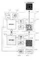
FIG. 1 is a schematic configuration diagram showing an embodiment of an electronic apparatus including a display device according to the present invention. 1A to 1C are schematic perspective views showing a plurality of specific examples of the electronic apparatus according to the present embodiment, and FIG. 1D is a display applied to the electronic apparatus according to the present embodiment. It is a schematic perspective view which shows the structural example of an apparatus. FIG. 2 is a block diagram illustrating a schematic configuration of the electronic apparatus according to the present embodiment, and FIG. 3 is a block diagram illustrating a schematic configuration of the display device applied to the electronic apparatus according to the present embodiment.
本発明の一実施形態に係る表示装置を備えた電子機器10は、例えば図1(a)〜(c)に示すように、少なくとも各種の情報を表示するための表示パネル40を備えた構成を有している。ここで、電子機器10は、例えば図1(a)に示すように、腕時計型やリストバンド型の外観を有し、ユーザ(利用者)の身体に装着されるスポーツウォッチやスマートウォッチであってもよいし、図1(b)に示すような、ユーザが手に持って使用するスマートフォンや携帯電話機であってもよいし、図1(c)に示すような、登山等でユーザがアウトドアで手に持って使用する携帯機器(例えばGPSロガー)であってもよい。なお、図1(a)〜(c)において、30はボタンスイッチやタッチパネル等の入力操作部であり、50はスピーカやブザー等の出力部である。表示パネル40や入力操作部30、出力部50を含む電子機器10の各構成については、詳しく後述する。 An
このような電子機器10において、表示パネル40は、例えば図1(d)に示すように、表示パネル40Aと表示パネル40Bとを有し、表示パネル40Aの表示領域と表示パネル40Bの表示領域とが重ね合わされた(積層された)構成を有している。ここで、ユーザの視野側(図面、上層側)に配置された表示パネル(第1の表示パネル)40Aは、単独で文字情報や画像情報等を反射型で視認性良く表示する特性を有している。更に、表示パネル40Aは、背面側(視野側の反対側;図面、下層側)に配置された表示パネル40Bに表示された文字情報や画像情報等が視野側に透過してユーザに良好に視認されるように、少なくとも透明又は半透明に状態を変化させることができる特性も有している。本実施形態においては、表示パネル40Aとして、例えば、比較的高い反射率で屋外視認性に優れる反射型でのモノクロ表示が可能で、かつ、半透過表示や全透過表示も可能なPN(Polymer Network;高分子分散)液晶パネルを良好に適用することができる。PN液晶パネルは、パネル平面に垂直方向に電界を形成することにより、液晶層内の高分子が電界方向に整列して光を透過する状態となり、一方、電界を形成せず高分子が散乱配列した状態では非透過となって光を乱反射又は拡散乱反射する状態となって、文字情報や画像情報等を反射型で表示することができる特性を有している。これにより、PN液晶パネルは、所定のセグメントや図形を組み合わせて非透過として外光を乱反射又は拡散乱反射することにより、文字情報や画像情報を簡易なモノクロ画像(又はモノトーン画像)として表示することができ、さらに、PN液晶パネルは、その表示状態を維持するために電力を必要としない特性を有しているため、一般に低消費電力で表示駆動することができる。なお、上記において表示パネル40は2枚の表示パネル(表示パネル40A、表示パネル40B)を有するものとしたが、2枚より多くの枚数の表示パネルを有するものであってもよい。 In such an
一方、ユーザの視野側の反対側(表示パネル40Aの背面側)に配置された表示パネル(第2の表示パネル)40Bは、単独で文字情報や画像情報等を高精細で優れた色彩表現や視覚効果により表示する特性を有している。更に、表示パネル40Bは、表示された文字情報や画像情報等が表示パネル40Aを透過してユーザに良好に視認されるように、光源(バックライト等)を備えた構成を有している。本実施形態においては、表示パネル40Bとして、例えば、高精細で色彩表現や視覚効果に優れた(リッチな)カラー表示が可能な透過型のTFT(Thin Film Transistor)カラー液晶パネルを良好に適用することができる。TFTカラー液晶パネルは、一般に、背面側(下層側)に配置された光源(バックライト)からの光を透過させることにより、文字情報や画像情報を豊かな色彩表現で視認性良く表示することができるという特長を有している。しかし、通常、上述したPN液晶パネルを適用した表示パネル40Aに比較して、消費電力が大きい。 On the other hand, the display panel (second display panel) 40B arranged on the opposite side of the user's visual field side (the back side of the
本実施形態に係る電子機器10は、具体的には、例えば図2に示すように、上述したPN液晶パネルを適用した表示パネル40Aを備えた内部回路100と、上述したTFTカラー液晶パネルを適用した表示パネル40Bを備えた内部回路200と、光源部300と、電源部400と、を有している。ここでは、本実施形態に係る電子機器10として、身体に装着して運動時や日常の各種のデータを収集して分析する機器、例えば手首に装着する腕時計型のスポーツウォッチ(図1(a)参照)に適用した場合について説明する。 Specifically, for example, as shown in FIG. 2, the
内部回路100は、例えば図2(a)に示すように、大別して、センサ部(検知部)110と、GPS機能部120と、入力操作部(検知部)130と、表示部140と、出力部150と、メモリ部160と、演算回路部(第1の演算回路部)170と、通信インターフェース部(以下、「通信I/F部」と記す)180と、を有している。 For example, as shown in FIG. 2A, the
センサ部110は、加速度センサやジャイロセンサ、地磁気センサ、気圧センサ、温湿度センサ、脈拍センサ、心拍センサ等のセンサ手段であり、ユーザの運動中や日常生活における各種の物理的又は生体的なデータ(センサデータ)を取得して演算回路部170に出力する。ここで、加速度センサやジャイロセンサ、地磁気センサ等のセンサ類は、ユーザの運動中、例えば毎秒100回以上の周期(100Hz以上のサンプリング周波数)でセンシング動作を実行してセンサデータを演算回路部170に出力する。 The
GPS機能部120は、GPSアンテナ及びGPS受信部を備え、GPSアンテナを介して複数のGPS衛星からの電波を受信することにより、GPS受信部が地理的な位置情報を取得して測位データとして演算回路部170に出力する。これにより、演算回路部170において、例えば、電子機器10を装着したユーザの現在位置及び移動経路が算出される。ここで、GPS機能部120は例えば1〜数秒に1回程度の周期でセンシング動作を実行して測位データを演算回路部170に出力する。 The
入力操作部130は、例えば電子機器10の筐体に設けられたボタンスイッチやスライドスイッチ、マイク等の入力手段であり、ユーザの入力操作に起因する各種の操作信号を演算回路部170に出力する。これにより、演算回路部170において、上述したセンサ部110やGPS機能部120におけるセンシング動作の設定や制御、表示部140や後述する表示部240に表示する項目や文字情報、画像情報の選択や設定等が行われる。 The
表示部140は、図3に示すように、上述したPN液晶パネルを適用した表示パネル40Aと画像メモリ(フレームメモリ)142と表示ドライバ(LCDドライバ)144とを備え、演算回路部170において生成される各種の情報を、所定の形態で表示する。ここで、本実施形態においては、PN液晶パネルの特性を利用して、演算回路部170により、表示パネル40Aが半透過状態(非透過の部分や領域を有する状態)、又は、全透過状態に制御される。すなわち、表示パネル40Aは、半透過状態においては特定のセグメントや図形等に対応する領域のみが光を乱反射又は拡散乱反射して白色表示として視認されることで反射型の表示がなされ、それ以外の領域では下層の表示パネル40Bに表示された画像が透過して視認される。また、全透過状態においては表示パネル40Aの表示領域の全体が透過状態となり、表示領域の全域で表示が行われず、下層の表示パネル40Bに表示された画像が略全て透過して視認される。これにより、表示部140は、演算回路部170により、大別して、演算回路部170において生成される各種の情報を半透過状態でセグメントや図形等により単独でモノクロ表示する形態と、後述する内部回路200の表示部240に表示される文字情報や画像情報等に連携して半透過状態でセグメントや図形等によりモノクロ表示する形態と、表示パネル40Aを全透過状態に設定して全域に何も表示しない形態と、に制御される。なお、表示部140及び内部回路200の表示部240における文字情報や画像情報等の表示例については、後述する表示形態において詳しく説明する。 As shown in FIG. 3, the
出力部150は、ブザーやスピーカ等の音響手段や、振動モータや振動子等の振動手段であり、所定の音色や音パターン、音声メッセージ等の音情報、あるいは、所定の振動パターンやその強弱等の振動情報を発生することにより、聴覚や触覚を通してユーザに各種の情報を提供又は報知する。ここで、出力部150は、上述した表示部140や内部回路200の表示部240に表示される文字情報や画像情報等に連動して、所定の音情報や振動情報を発生させるものであってもよい。 The
メモリ部160は、センサ部110において取得したセンサデータやGPS機能部120において取得した測位データを所定の記憶領域に保存する。また、メモリ部160は、演算回路部170において所定の制御プログラムやアルゴリズムプログラムを実行する際に使用するデータやその際に生成されるデータ、表示部140に表示するためのデータ等を保存する。また、メモリ部160は、演算回路部170において実行される制御プログラムやアルゴリズムプログラムが保存されるものであってもよい。なお、メモリ部160は、その一部又は全部が、例えばメモリカード等のリムーバブル記憶媒体としての形態を有し、電子機器10に対して着脱可能に構成されているものであってもよい。 The
演算回路部170は、CPU(中央演算処理装置)やMPU(マイクロプロセッサ)等の演算装置であって、所定の制御プログラムやアルゴリズムプログラムを実行することにより、センサ部110やGPS機能部120におけるセンシング動作や、表示部140や出力部150における各種の情報の提供、通信I/F部180における各種のデータの送受信等の、各種の動作を制御する。特に、演算回路部170は、上述した表示部140における表示パネル40Aの透過状態(非透過、半透過、全透過の各状態)を制御するとともに、後述する内部回路200の演算回路部270と連携かつ同期して表示部140における各種の情報の表示形態を制御する。 The
本実施形態においては、演算回路部170は、低消費電力で表示駆動される表示部140(表示パネル40A)や、周期的にセンシング動作を行うセンサ部110やGPS機能部120、低消費電力でデータを送受信する通信I/F部180等を制御することができる程度の処理能力を有していればよい。すなわち、演算回路部170は、動作クロックが後述する内部回路200の演算回路部270の動作クロックより低速で、比較的処理能力が低い演算回路を適用することができる。そして、このような演算回路は、一般に消費電力を比較的低く抑えることができる。これは換言すると、演算回路部170として、比較的処理能力が低く、かつ、消費電力の低い演算回路(ローパワー、ローパフォーマンスのプロセッサ)を適用することができることを意味する。ここで、演算回路部170において実行される制御プログラムやアルゴリズムプログラムは、上述したメモリ部160に保存されているものであってもよいし、演算回路部170の内部に予め組み込まれているものであってもよい。なお、本実施形態に係る電子機器10の制御方法ついては詳しく後述する。 In the present embodiment, the
通信I/F部180は、送信回路及び受信回路を備え、本実施形態に係る手首に装着した腕時計型の電子機器10と外部の電子機器(便宜的に「外部機器」と記す;図示を省略)との間で、所定の通信方式により各種のデータを送受信する。ここで、通信I/F部180を介して通信を行う外部機器は、例えば各種のセンサ類を備え、ユーザが胸部や腰部等、身体の他の部位に装着するセンサ機器(図示を省略)等である。電子機器10は、例えば、このような外部機器において所定の周期やタイミングで収集されたセンサデータ等を、通信I/F部180を介して随時受信して演算回路部170やメモリ部160に転送する。なお、通信I/F部180において、無線通信により外部機器との間でデータを送受信する場合には、例えばブルートゥースローエナジー(Bluetooth(登録商標) low energy(LE))通信等の低消費電力の無線通信方式が適用される。また、通信I/F部180において、有線通信により外部機器との間でデータを送受信するものであってもよく、その場合には、例えばUSB(Universal Serial Bus)規格等の有線通信方式が適用される。 The communication I / F unit 180 includes a transmission circuit and a reception circuit. The wristwatch-type
内部回路200は、例えば図2(b)に示すように、大別して、入力操作部230と、表示部240と、メモリ部260と、演算回路部(第2の演算回路部)270と、通信I/F部280と、を有している。 For example, as shown in FIG. 2B, the
入力操作部230は、例えば上述した内部回路100の表示部140に設けられた表示パネル40Aの視野側に配置されたタッチパネル等の入力手段であり、ユーザの入力操作に起因する各種の操作信号を演算回路部270に出力する。これにより、演算回路部270において、上述した表示部140や表示部240に表示する項目や文字情報、画像情報の選択や設定等が行われる。 The
表示部240は、図3に示すように、上述したTFTカラー液晶パネルを適用した表示パネル40Bと画像メモリ242と表示ドライバ244とを備え、演算回路部270において生成される各種の情報を、所定の形態で表示する。ここで、本実施形態においては、透過型のTFTカラー液晶パネルの特性を利用して、表示パネル40Bに所定のカラー画像を表示した状態で、背面側(視野側の反対側)に設けられた光源(バックライト)を点灯することにより、当該カラー画像が表示パネル40Aを介してユーザにより視認される。特に、本実施形態においては、表示パネル40Bに表示されるカラー画像は、演算回路部270により、上述した内部回路100の表示部140に設けられた表示パネル40Aの透過状態(半透過、全透過の各状態)、及び、表示パネル40Aに表示される画像に連携して制御される。これにより、表示部240は、演算回路部270により、大別して、演算回路部270において生成される各種の情報を単独でカラー表示する形態と、上述した内部回路100の表示パネル40Aにセグメントや図形等によりモノクロ表示される文字情報や画像情報等に連携してカラー表示する形態と、表示パネル40Bの全域で表示を行わず、視野側に配置された表示パネル40Aに対して無反射層(光が殆ど反射しない特性を有する層)として機能する形態と、に制御される。 As shown in FIG. 3, the
メモリ部260は、演算回路部270において所定の制御プログラムやアルゴリズムプログラムを実行する際に使用するデータやその際に生成されるデータ、表示部240に表示するためのデータ等を保存する。また、メモリ部260は、演算回路部270において実行される制御プログラムやアルゴリズムプログラムが保存されるものであってもよい。なお、メモリ部260は、上述した内部回路100に設けられるメモリ部160と一体的に構成されているものであってもよい。 The
演算回路部270は、上述した内部回路100の演算回路部170と同様に、CPUやMPU等の演算装置であって、所定の制御プログラムやアルゴリズムプログラムを実行することにより、表示部240における各種の情報の表示や、後述する通信I/F部280における各種のデータの送受信等の、各種の動作を制御する。特に、演算回路部270は、上述した内部回路100の演算回路部170と連携かつ同期して表示部240における各種の情報の表示形態を制御する。 The
本実施形態においては、演算回路部270は、比較的消費電力が大きく多彩なカラー表示が可能な表示部240(表示パネル40B)や、比較的容量の大きい各種のデータを高速で送受信する通信I/F部280等を制御することができる程度の処理能力を有している。すなわち、演算回路部270は、動作クロックが内部回路100の演算回路部170の動作クロックより高速で、比較的処理能力が高い演算回路が適用される。そして、このような演算回路は、一般に消費電力が比較的高い傾向にある。これは換言すると、演算回路部270として、比較的処理能力が高く、かつ、消費電力の高い演算回路(ハイパワー、ハイパフォーマンスのプロセッサ)を適用する必要があることを意味する。すなわち、演算回路部270は、動作周波数が演算回路部170の動作周波数より高く、処理能力が演算回路部170の処理能力より高く、消費電力が演算回路部170の消費電力より高いものである。ここで、演算回路部270において実行される制御プログラムやアルゴリズムプログラムは、上述したメモリ部260に保存されているものであってもよいし、演算回路部270の内部に予め組み込まれているものであってもよい。 In the present embodiment, the
通信I/F部280は、送信回路及び受信回路を備え、本実施形態に係る電子機器10と外部機器との間で、所定の通信方式により各種のデータを送受信する。ここで、通信I/F部280を介して通信を行う外部機器は、例えばスマートフォンやパーソナルコンピュータ等の高機能の情報処理装置(図示を省略)等である。電子機器10は、このような外部機器との間で、比較的容量の大きいデータを、通信I/F部280を介して高速で送信する。具体的には、通信I/F部280は、例えば、電子機器10が収集したセンサデータ等を外部機器に送信したり、外部機器から送信される各種の情報を受信したりする。なお、通信I/F部280において、無線通信により外部機器との間でデータを送受信する場合には、例えばブルートゥース(Bluetooth(登録商標))通信やワイファイ(Wi-Fi;wireless fidelity(登録商標))通信等の各種の無線通信方式が適用される。また、通信I/F部280において、有線通信により外部機器との間でデータを高速で送受信するものであってもよく、その場合には、例えばUSB規格等における高速通信規格に対応した有線通信方式が適用される。 The communication I /
光源部300は、図3に示すように、バックライト302とバックライト制御部304とを備え、上述した内部回路200の表示部240に設けられる表示パネル40Bや、内部回路100の表示部140に設けられる表示パネル40Aの表示状態に応じて、バックライト302のON(点灯)、OFF(消灯)状態が制御される。バックライト302は表示パネル40Bの背面側に配置され、例えば、複数のLED(発光素子)と、導光板や光拡散フィルム等の各種の光学部材とを用いた面光源が適用される。バックライト制御部304は、図2、図3に示すように、少なくとも内部回路100の演算回路部170からの制御信号に基づいて、バックライト302のON、OFF状態を制御する。なお、バックライト制御部304は、演算回路部170からの制御信号のほかに、内部回路200の演算回路部270からの制御信号に基づいて、バックライト302のON、OFF状態を制御するものであってもよい。 As shown in FIG. 3, the
電源部400は、上述した内部回路100、200及び光源部300の各構成に対して所定の駆動電力を生成して出力する。ここで、電源部400は、例えば市販のコイン型電池やボタン型電池等の一次電池、リチウムイオン電池やニッケル水素電池等の二次電池を適用することができる。また、電源部400は、上記の一次電池や二次電池のほか、振動や光、熱、電磁波等のエネルギーにより発電する環境発電(エナジーハーベスト)技術による電源等を単独で、あるいは、併用して適用することもできる。 The
このように、本実施形態に係る電子機器10においては、比較的高い反射率で屋外視認性に優れる反射型での簡易なモノクロ表示が可能で、かつ、半透過表示や全透過表示が可能な表示パネル40Aと、高精細で色彩表現や視覚効果に優れたカラー表示が可能な表示パネル40Bとを備え、これらの表示パネル40A、40Bが視野側から見て重なるように積層された構成を有している。これらの表示パネル40A、40Bは、各々の表示形態に応じた処理能力を有する独立した演算回路部170、270により制御される。そして、これらの演算回路部170、270が相互に連携することにより、電子機器10における電力の消費を抑制しつつ、表示パネル40における種々の表示形態が制御される。 As described above, in the
<表示形態>
次に、本実施形態に係る電子機器における画面表示の表示形態について説明する。
図4は、本実施形態に係る電子機器における画面表示の第1の表示形態の例を示す概略図であり、図5、図6は、本実施形態に係る電子機器における画面表示の第2の表示形態の例を示す概略図であり、図7、図8は、本実施形態に係る電子機器における画面表示の第3の表示形態の例を示す概略図である。<Display format>
Next, a display form of screen display in the electronic apparatus according to the present embodiment will be described.
FIG. 4 is a schematic diagram illustrating an example of a first display form of screen display in the electronic device according to the present embodiment, and FIGS. 5 and 6 illustrate a second screen display in the electronic device according to the present embodiment. FIG. 7 and FIG. 8 are schematic diagrams illustrating an example of a third display mode of screen display in the electronic apparatus according to the present embodiment.
(第1の表示形態)
上述した構成を有する電子機器10における第1の表示形態においては、図1(d)に示したように、ユーザの視野側から見て重なるように配置された表示パネル40A、40Bのうち、図4に示すように、視野側(図1(d)の上層側)の表示パネル40Aに所定の文字情報や画像情報等が表示されるように表示部140が制御される。すなわち、内部回路100の演算回路部170において生成され、表示部140の画像メモリ142に保存された文字情報や画像情報等が、表示ドライバ144により表示パネル40Aにセグメントや図形等による比較的高い反射率で簡易なモノクロ画像(第1の画像)として反射型で表示されるとともに、表示パネル40Aの文字情報や画像情報等を表示していない領域が透過状態に設定される。(First display form)
In the first display form in the
一方、表示パネル40Aの背面側(図1(d)の下層側)の表示パネル40Bには何も情報が表示されないように表示部240が制御される。すなわち、少なくとも、内部回路200の演算回路部270及び表示部240(画像メモリ242、表示ドライバ244、表示パネル40B)が継続的又は断続的に休止状態に設定される。ここで、内部回路200の演算回路部270及び表示部240における休止状態は、演算回路部270と内部回路100の演算回路部170とが相互に連携することにより制御される。具体的には、演算回路部270は、内部回路100の演算回路部170に対して、表示パネル40Bにカラー表示を行わず休止状態に移行する連携信号を送信した後、少なくとも表示部240への電力の供給を抑制又は遮断して、休止状態に移行する。演算回路部170は、演算回路部270から上記の連携信号を受信することにより、表示パネル40Aに文字情報や画像情報等をモノクロ画像により表示するとともに、表示パネル40Aの文字情報や画像情報等を表示していな領域を透過状態に設定し、その状態を継続する。 On the other hand, the
さらに、演算回路部170は、演算回路部270から上記の連携信号を受信することにより、光源部300のバックライト制御部304に対してバックライト302をOFF(消灯)するように制御する。これにより、表示パネル40Bは、半透過状態に設定された表示パネル40Aの背面側に配置された無反射層として機能する。 Furthermore, the
このように電子機器10における第1の表示形態においては、図4に示すように、視野側(上層側)の表示パネル40Aに文字情報や画像情報等がセグメントや図形等による比較的高い反射率で簡易なモノクロ画像として反射型で表示されるとともに、表示パネル40Aの文字情報や画像情報等を表示していない領域が透過状態に設定され、また、背面側(下層側)の表示パネル40Bは無反射層として機能している。これにより、表示パネル40Aの文字情報や画像情報等を表示していない領域は黒く見えることになる。このため、ユーザは、屋外や明るい環境下においても、表示パネル40Aに表示された文字情報や画像情報等を良好に視認することができる。また、第1の表示形態においては、当該表示状態を維持している間、内部回路100の表示部140が低消費電力で表示駆動されるとともに、内部回路200の演算回路部270及び表示部240、並びに光源部300がほとんど電力を消費することがないので、電子機器10の消費電力を大幅に抑制することができる。 As described above, in the first display form of the
(第2の表示形態)
電子機器10における第2の表示形態においては、図5に示すように、ユーザの視野側の表示パネル40Aには何も情報が表示されないように表示部140が制御される。すなわち、少なくとも、表示パネル40Aの表示領域全体が透過状態に設定されるとともに、内部回路100の表示部140の画像メモリ142及び表示ドライバ144が継続的又は断続的に休止状態に設定される。ここで、内部回路100の表示部140における休止状態は、演算回路部170と内部回路200の演算回路部270とが相互に連携することにより制御される。具体的には、演算回路部170は、演算回路部270に対して、表示パネル40Aに何も情報を表示せず、表示領域全体を透過状態に設定するとともに、表示部140を休止状態に移行する連携信号を送信した後、少なくとも表示部140への電力の供給を抑制して、休止状態に移行する。(Second display form)
In the second display form of the
一方、演算回路部270は、演算回路部170から上記の連携信号を受信することにより、表示パネル40Aの背面側の表示パネル40Bに所定の文字情報や画像情報等を表示するように表示部240を制御する。すなわち、演算回路部270において生成され、表示部240の画像メモリ242に保存された文字情報や画像情報等が、表示ドライバ244により表示パネル40Bに高精細で色彩表現や視覚効果に富む(リッチな)カラー画像(第2の画像)として表示される。 On the other hand, the
さらに、演算回路部170は、少なくとも電子機器10の画面表示を視認するためのユーザの意図的な動作に基づいて、光源部300のバックライト制御部304に対してバックライト302をON(点灯)又はOFF(消灯)させるように制御する。具体的には、演算回路部170は、ユーザが画面表示を視認する際のユーザの意図的な動作に関連して、センサ部110により取得されるセンサデータや入力操作部130からの操作信号等(特定の状態)を検知した場合には、図5(a)に示すように、予め表示パネル40Bに所定の文字情報や画像情報等をカラー表示した状態で、光源部300のバックライト制御部304に対してバックライト302をON(点灯)させるように制御する。あるいは、演算回路部170は、上記のセンサデータや操作信号等を検知した場合には、図5(a)に示すように、演算回路部270に所定の連携信号を送信して、表示パネル40Bに所定の文字情報や画像情報等がカラー表示されるように表示部240を制御するとともに、光源部300のバックライト302をON(点灯)させるように制御する。これにより、表示パネル40Aの背面側の表示パネル40Bにバックライト302から光が照射されて、表示パネル40Bにカラー表示された文字情報や画像情報等が、全透過状態に設定された表示パネル40Aを介して(透過して)、ユーザにリッチなカラー画像として視認される。一方、演算回路部170が、ユーザの意図的な視認動作を検知していない状態では、図5(b)に示すように、少なくともバックライト制御部304に対してバックライト302をOFF(消灯)させるように制御する。あるいは、演算回路部170は、ユーザの意図的な視認動作を検知していない状態では、演算回路部270に所定の連携信号を送信して、表示パネル40Bにカラー画像を表示しないように表示部240を制御するとともに、バックライト302をOFF(消灯)させるように制御する。 Further, the
このように電子機器10における第2の表示形態においては、図5に示すように、表示パネル40Aが全透過状態に設定されるとともに、表示パネル40Aの背面側(下層側)の表示パネル40Bに文字情報や画像情報等がリッチなカラー画像により表示される。そして、ユーザが電子機器10の画面表示を視認する意図的な動作を行った場合のみ、表示パネル40Bにバックライト302の光が照射されて、ユーザは、表示パネル40Bに表示された文字情報や画像情報等を全透過状態に設定された表示パネル40Aを介して、リッチなカラー画像として視認することができる。また、第2の表示形態においては、当該表示状態を維持している間、内部回路100の表示部140が低消費電力で表示駆動されるとともに、ユーザが意図的な視認動作をしていない状態では少なくとも光源部300が電力を消費することがないので、電子機器10の消費電力を大幅に抑制することができる。なお、図5においては、ユーザが視認する画面表示として、表示パネル40Bに文字情報をカラー表示した場合について図示したが、図6に示すように、文字情報を含む任意の画像情報を表示パネル40Bにリッチなカラー画像として表示するものであってもよい。ここで、図6(a)、(c)は、表示パネル40Bに任意の画像情報をカラー表示し、バックライト302をON(点灯)した状態を示す概略図であり、図6(b)は、図6(a)に示した表示形態において、バックライト302をOFF(消灯)した状態を示す概略図である。 As described above, in the second display mode of the
(第3の表示形態)
電子機器10における第3の表示形態においては、図7に示すように、ユーザの視野側の表示パネル40Aに所定の文字情報や画像情報等が表示されるように表示部140が制御される。すなわち、演算回路部170において生成され、表示部140の画像メモリ142に保存された文字情報や画像情報等が、表示ドライバ144により表示パネル40Aにセグメントや図形等による比較的高い反射率で簡易なモノクロ画像として反射型で表示されるとともに、表示パネル40Aの文字情報や画像情報等を表示していない領域が透過状態に設定される。ここで、内部回路100の表示部140における表示状態は、演算回路部170と内部回路200の演算回路部270とが相互に連携することにより制御される。具体的には、演算回路部170は演算回路部270に対して、表示パネル40Aに表示されるモノクロ画像や、その表示タイミング、表示形態等に関する連携信号を送信する。(Third display form)
In the third display mode of the
一方、演算回路部270は、演算回路部170から上記の連携信号を受信することにより、表示パネル40Aの背面側の表示パネル40Bに、表示パネル40Aに表示されたモノクロ画像に連携した所定の文字情報や画像情報等を所定のタイミングで表示するように表示部240を制御する。ここで、内部回路200の表示部240における表示状態は、内部回路100の演算回路部170と演算回路部270とが相互に連携することにより制御される。すなわち、演算回路部270において生成され、画像メモリ242に保存された文字情報や画像情報等が、表示ドライバ244により表示パネル40Bにリッチなカラー画像として表示され、さらに、演算回路部270と演算回路部170とが相互に連携することにより、表示パネル40Aに表示される簡易なモノクロ画像に重ね合わされて表示される。 On the other hand, the
ここで、表示パネル40Bに表示されるカラー画像は、例えば図7(a)、図8(a)に示すように、セグメントや図形等により表示パネル40Aに表示されるモノクロ画像の背景画像や装飾画像として用いられるものであってもよい。また、カラー画像は、表示パネル40Aに表示されるモノクロ画像が示す情報に対して、関連する情報を示すものであってもよいし、全く異なる種類の情報を示すものであってもよい。具体的には、例えば図8(b)に示すように、表示パネル40Aに表示される、ペースやラップタイム等の数値情報を示すモノクロ画像に対して、当該ペースやラップタイム等の分析結果に基づく支援情報を示すカラー画像(例えばペースアップを促す画像等)が表示パネル40Bに表示されるものであってもよい。また、例えば図8(c)に示すように、表示パネル40Aに表示される、移動距離等の数値情報を示すモノクロ画像に対して、ユーザの現在位置や移動軌跡等を示すカラー画像(地図)が表示パネル40Bに表示されるものであってもよい。 Here, as shown in FIGS. 7A and 8A, for example, the color image displayed on the
本実施形態においては、上述したように、演算回路部170と演算回路部270とが相互に連携かつ同期して動作することにより、表示パネル40Aに表示されるモノクロ画像と表示パネル40Bに表示されるカラー画像とが重ね合わされて多様な表示形態が実現される。このような多様な表示形態を実現するためには、演算回路部170及び演算回路部270は、少なくとも、それぞれの「現在の動作状態」や「表示している情報」、「情報の表示形態」等を把握し、かつ、同期して動作する必要がある。そのため、演算回路部170と演算回路部270との間で通信される連携信号は、少なくとも、これらの情報を含んで、常時又は所定のタイミングで随時送受信される。 In the present embodiment, as described above, the
さらに、演算回路部170は、上述した第2の表示形態と同様に、少なくとも電子機器10の画面表示を視認するためのユーザの意図的な動作に基づいて、光源部300のバックライト302をON(点灯)又はOFF(消灯)させるように制御する。そして、演算回路部170は、ユーザが画面表示を視認する際の意図的な動作に関連するセンサデータや操作信号等を検知した場合には、図7(a)に示すように、予め表示パネル40Aに所定の文字情報や画像情報等をモノクロ表示するとともに、表示パネル40Bに連携する文字情報や画像情報等をカラー表示した状態で、バックライト302をON(点灯)させるように制御する。あるいは、演算回路部170は、上記のセンサデータや操作信号等を検知した場合には、図7(a)に示すように、表示パネル40Aに所定の文字情報や画像情報等をモノクロ表示するとともに、演算回路部270に所定の連携信号を送信して、表示パネル40Bに連携する文字情報や画像情報等がカラー表示されるように表示部240を制御し、さらに、光源部300のバックライト302をON(点灯)させるように制御する。これにより、表示パネル40Bにバックライト302から光が照射されて、表示パネル40Aに表示された比較的高い反射率で簡易なモノクロ画像と、表示パネル40Bに表示されたリッチなカラー画像とを、重ね合わせた画像や組み合わせた画像(以下、便宜的に「重合画像」と総称する)がユーザに視認される。一方、演算回路部170が、ユーザの意図的な視認動作を検知していない状態では、上述した第2の表示形態と同様に、図7(b)に示すように、バックライト302をOFF(消灯)させるように制御する。あるいは、演算回路部170は、ユーザの意図的な視認動作を検知していない状態では、演算回路部270に所定の連携信号を送信して、表示パネル40Bにカラー画像を表示しないように表示部240を制御するとともに、バックライト302をOFF(消灯)させるように制御する。 Further, the
このように電子機器10における第3の表示形態においては、図7に示すように、表示パネル40Aにセグメントや図形等により比較的高い反射率で簡易なモノクロ画像が反射型で表示されるとともに、表示パネル40Bにモノクロ画像に連携したリッチなカラー画像が所定のタイミングで表示される。そして、ユーザが電子機器10の画面表示を視認する意図的な動作を行った場合のみ、バックライト302の光が表示パネル40Bに照射されて、ユーザは、表示パネル40Aに表示されたモノクロ画像と、表示パネル40Bに表示されたカラー画像とを、重ね合わせた重合画像を視認することができる。このとき、ユーザは、屋外や明るい環境下においても、少なくとも外光の反射を利用して表示を行う表示パネル40Aに表示された文字情報や画像情報等を、高いコントラストのモノクロ画像として良好に視認することができる。また同時に、ユーザは、表示パネル40Bに表示された文字情報や画像情報等を、半透過状態に設定された表示パネル40Aを介して、リッチなカラー画像として視認することができる。また、第3の表示形態においては、当該表示状態を維持している間、内部回路100の表示部140が低消費電力で表示駆動されるとともに、ユーザが意図的な視認動作をしていない状態では少なくとも光源部300が電力を消費することがないので、電子機器10の消費電力を大幅に抑制することができる。 As described above, in the third display form in the
<電子機器の制御方法>
次に、本実施形態に係る電子機器の制御方法(情報表示方法)について説明する。ここでは、図1(a)に示したような腕時計型やリストバンド型の外観を有する電子機器10をユーザが手首に装着して、ランニングやウォーキング等の運動時や、日常生活における各種のデータを記録する場合において、各種の情報を表示パネル40に表示して提供する際の制御方法について説明する。ここで、以下に示す一連の処理動作は、内部回路100の演算回路部170及び内部回路200の演算回路部270において所定のアルゴリズムプログラムを実行することにより実現される。<Control method of electronic equipment>
Next, an electronic device control method (information display method) according to the present embodiment will be described. Here, the user wears an
図9は、本実施形態に係る電子機器の制御方法の一例を示すフローチャートである。図10は、本実施形態に係る電子機器の制御方法におけるユーザの意図的な視認動作の検知方法の一例を示す概略図である。ここでは、上述した各表示形態(図4〜図8参照)を適宜参照しながら説明する。 FIG. 9 is a flowchart illustrating an example of an electronic device control method according to the present embodiment. FIG. 10 is a schematic diagram illustrating an example of a method for detecting a user's intentional visual recognition operation in the electronic device control method according to the present embodiment. Here, description will be given with appropriate reference to each of the display forms described above (see FIGS. 4 to 8).
本実施形態に係る電子機器の制御方法においては、例えば図9のフローチャートに示すように、まず、ユーザは手首に装着した(又は装着する)電子機器10について、実行する機能やアプリケーション(ソフトウェア)を設定するとともに、消費電力に関わる動作モードを設定する(ステップS102)。具体的には、ユーザが電子機器10の筐体に設けられたボタンスイッチやスライドスイッチ等の入力操作部130や、表示パネル40Aの視野側に配置されたタッチパネル等の入力操作部230を操作することにより、演算回路部170、270において電子機器10の消費電力を規定する複数の動作モードのいずれかが設定される。これにより、内部回路100の演算回路部170と内部回路200の演算回路部270とは、相互に連携し、常時又は所定のタイミングで随時通信を行い、設定された動作モードに関する連携信号を送受信する。ここで、本実施形態においては、電子機器10の動作モードとして、例えば電子機器10における消費電力を抑制しつつ、各種の機能動作を実行する「パワーセーブモード」と、パフォーマンス(処理速度や画面表示の見栄え等)を重視して各種の機能動作を実行する「通常モード」とが予め用意されていて、ユーザによりいずれかの動作モードが選択されて設定される。 In the electronic device control method according to the present embodiment, for example, as shown in the flowchart of FIG. 9, first, the user executes functions or applications (software) to be executed on the
次いで、演算回路部170は、ステップS102において設定された動作モードを判別し(ステップS104)、その結果に応じて、表示パネル40における画面表示の表示形態を制御する。具体的には、演算回路部170は、まず、ユーザにより設定された動作モードがパワーセーブモードであるか、又は、通常モードであるかを判別する。動作モードがパワーセーブモードである場合には、演算回路部170は、表示モード「A」を適用して、設定されている機能やアプリケーションに応じた文字情報や画像情報等を表示パネル40に低消費電力で表示するように制御する(ステップS112)。ここで、表示モード「A」においては、上述した第1の表示形態(図4参照)に示したように、視野側の表示パネル40Aにセグメントや図形等によりモノクロ画像を半透過状態で表示した状態と、背面側の表示パネル40Bには何も表示せず無反射層として機能させた状態との組み合わせによる画面表示が行われる。すなわち、パワーセーブモードにおいて適用される表示モード「A」においては、視野側の表示パネル40Aに単独で文字情報や画像情報等が比較的高い反射率で簡易なモノクロ画像により反射型で表示される(ステップS114)。このモノクロ画像による画面表示は所定の時間間隔で更新される。 Next, the
そして、演算回路部170は、このパワーセーブモードにおける画面表示の動作中に、ユーザの意図的な視認動作(トリガ)を検知したか否かを常時又は所定の間隔で監視する(ステップS116)。具体的には、演算回路部170は、ユーザが電子機器10の表示パネル40の画面表示を視認する際の意図的な動作に関連して、センサ部110により取得されるセンサデータや入力操作部130からの操作信号等を検知した場合には、後述するステップS106以降の処理動作を実行して、所定の表示形態でカラー表示を行う。ここで、ユーザの意図的な視認動作として検知される例としては、ボタンスイッチを押下した場合やタッチパネルをタッチした場合、加速度センサやジャイロセンサによる視認動作特有の出力を検出した場合、加速度センサ等で予め規定された特定のジェスチャーやショック(衝撃等)を検出した場合、マイクにより特定のボイスコマンドを入力した場合等を適用することができる。より具体的には、例えば図10(b)、(d)に示すように、ユーザが電子機器10を装着した腕を視界の範囲内に持ち上げて、表示パネル40の画面表示を凝視する際に、加速度センサやジャイロセンサから出力される特定の信号や波形等を検出した場合に、演算回路部170はユーザが意図的な視認動作を行ったものと判定する。 Then, the
一方、ユーザの意図的な視認動作が検知されていない場合には、演算回路部170は、表示モード「A」による比較的高い反射率での簡易なモノクロ表示を継続する。すなわち、例えば図10(a)、(c)に示すように、ユーザが電子機器10を装着した腕を無意識に下げたり振ったりしている状態では、加速度センサやジャイロセンサから出力される信号や波形等に基づいて、演算回路部170はユーザが表示パネル40の画面表示を見ていない(視認動作を行っていない)ものと判定する。この場合、演算回路部170は、パワーセーブモードを維持して、低消費電力で表示駆動する表示モード「A」による画面表示を継続する。 On the other hand, when the user's intentional visual recognition operation is not detected, the
動作モードを判別する処理(ステップS104)において、動作モードが通常モードである場合、あるいは、ステップS116においてユーザの意図的な視認動作(トリガ)を検知した場合には、演算回路部170は、電子機器10に設定されて実行される機能やアプリケーション等の種別を判別し(ステップS106)、その結果に応じて、表示パネル40における画面表示の表示形態を制御する。具体的には、演算回路部170は、まず、当該機能やアプリケーション等の種別が、所定の文字情報や画像情報等を、単独のカラー画像で表示する表示形態(以下、「単独カラー表示モード」と記す)に適しているものであるか、又は、モノクロ画像とカラー画像を重ね合わせたり組み合わせたりした重合画像で表示する表示形態(以下、「リッチカラー表示モード」と記す)に適しているものであるかを判別する。ここで、機能やアプリケーション等の種別は、表示パネル40における画面表示の表示形態に応じて、予め設定されているものであってもよい。実行される機能やアプリケーション等が単独カラー表示モードに適しているものである場合には、演算回路部170は、表示モード「B」を適用して表示パネル40の消費電力を抑制して表示駆動を行う(ステップS122)。ここで、表示モード「B」においては、上述した第2の表示形態(図5、図6参照)に示したように、視野側の表示パネル40Aには何も表示しない全透過状態と、背面側の表示パネル40Bにカラー画像を表示した状態との組み合わせによる画面表示が行われる。すなわち、通常モードに適用される表示モード「B」においては、背面側の表示パネル40Bに単独で文字情報や画像情報等がリッチなカラー画像により表示され、全透過状態の表示パネル40Aを透過して表示される(ステップS124)。このカラー画像による画面表示は所定の時間間隔で更新される。 In the process of determining the operation mode (step S104), when the operation mode is the normal mode, or when the user's intentional visual recognition operation (trigger) is detected in step S116, the
そして、演算回路部170は、この通常のカラー画像による画面表示が、予め設定された制限時間を超過(タイムアウト)したか否かを監視する(ステップS126)。ここで、制限時間は、ユーザが任意に設定するものであってもよいし、予め設定されたデフォルト値であってもよい。演算回路部170は、上記の制限時間を超過するまで通常のカラー画像による画面表示を継続するように、内部回路200の演算回路部270に連携信号を送信する。一方、通常のカラー画像による画面表示が制限時間を超過した場合には、演算回路部170は、ステップS104に戻って、設定されている動作モードに応じて、上述した一連の処理動作を再度実行する。 Then, the
一方、電子機器10において実行される機能やアプリケーション等の種別を判別する処理(ステップS106)において、当該機能やアプリケーション等がリッチカラー表示モードに適しているものである場合には、演算回路部170は、表示モード「C」を適用して高コントラストのモノクロ画像とリッチなカラー画像が重ね合わされて表示(重合表示)されるように表示パネル40を表示駆動する(ステップS132)。ここで、表示モード「C」においては、上述した第3の表示形態(図7、図8参照)に示したように、視野側の表示パネル40Aにセグメントや図形等によりモノクロ画像を半透過状態で表示した状態と、背面側の表示パネル40Bにカラー画像を表示した状態との重ね合わせや組み合わせによる画面表示が行われる。すなわち、通常モードに適用される表示モード「C」においては、視野側の表示パネル40Aにセグメントや図形等により、比較的高い反射率で表示される簡易なモノクロ画像と、背面側の表示パネル40Bに表示されるリッチなカラー画像とが重ね合わされて表示される。この重合画像による画面表示は所定の時間間隔で更新される。 On the other hand, in the process of determining the type of function or application executed in the electronic device 10 (step S106), if the function or application is suitable for the rich color display mode, the
そして、演算回路部170は、この重合画像による画面表示が、予め設定された制限時間を超過(タイムアウト)したか否かを監視する(ステップS136)。演算回路部170は、上記の制限時間を超過するまで重合画像による画面表示を継続するように、演算回路部270に連携信号を送信する。一方、重合画像による画面表示が制限時間を超過した場合には、演算回路部170は、ステップS104に戻って、設定されている動作モードに応じて、上述した一連の処理動作を再度実行する。 Then, the
なお、図9に示したフローチャートにおいては図示を省略したが、演算回路部170、270は、上述した一連の処理動作の実行中、処理動作を中断又は終了させる操作や状態の変化を常時監視して、当該操作や状態変化を検出した場合には、処理動作を強制的に終了する。具体的には、演算回路部170、270は、ユーザによる電子機器10の電源スイッチのOFF(電源遮断)操作や、電源部400における電池残量の低下、実行中の機能やアプリケーションの異常等を検出して、一連の処理動作を強制的に中断して終了する。 Although not shown in the flowchart shown in FIG. 9, the
このように、本実施形態においては、電子機器10の動作モードをパワーセーブモードに設定した状態では、表示パネル40にセグメントや図形等による比較的高い反射率で簡易なモノクロ画像が表示される。そして、電子機器10を装着したユーザが、表示パネル40の画面表示を視認する意図的な動作を行った場合にのみ、動作モードがパワーセーブモードから通常モードに移行し(すなわち、表示モードが切り替わり)、所定の表示形態でカラー表示が行われる。通常モードにおいては、電子機器10において実行される機能やアプリケーション等の種別に応じて、カラー画像単独のリッチなカラー表示、又は、高コントラストのモノクロ画像とリッチなカラー画像の重合画像による表示が行われる。 As described above, in the present embodiment, when the operation mode of the
したがって、本実施形態によれば、ユーザが電子機器を装着していない状態や、装着した状態で画面表示を視認していない場合には低消費電力で高コントラストのモノクロ表示が行われ、ユーザが電子機器の画面表示を視認する意図的な動作を行った場合にのみ所定の表示形態でカラー表示が実行されるので、消費電力を抑制して駆動時間を改善しつつ、所望の情報を多様な表示形態のカラー表示により視認性よく提供することができる。 Therefore, according to the present embodiment, when the user does not wear the electronic device or when the screen display is not visually recognized in the worn state, the monochrome display with low power consumption and high contrast is performed. Since color display is executed in a predetermined display form only when an intentional operation for visually recognizing the screen display of an electronic device is performed, a variety of desired information can be obtained while reducing power consumption and improving drive time. It can be provided with good visibility by the color display of the display form.
また、本実施形態によれば、電子機器10において実行される機能やアプリケーション等の種別に応じて、カラー表示の表示形態が制御されるので、特定の機能やアプリケーション等においてのみ、重合画像による画面表示を実現しつつ、その他の機能やアプリケーション等においては通常のカラー表示を行うことにより、消費電力を抑制することができる。 In addition, according to the present embodiment, since the display form of color display is controlled according to the type of function or application executed in the
ここで、本実施形態の作用効果について具体的に検証すると、一般に、カラー表示が可能な表示装置を備えた携帯型の電子機器においては、単一のカラー液晶表示パネルを備えた表示部と、単一演算回路(プロセッサ)とを有している。このような電子機器において、各種の情報を高精細で色彩表現や視覚効果に優れたリッチなカラー画像により表示したり、表示部や外部機器等に、大量のデータを転送したりするためには、本実施形態における演算回路部270と同様に、演算処理能力が高く、かつ、消費電力の高い演算回路を適用する必要がある。そして、この演算回路は、ユーザへの各種の情報の提供時だけでなく、種々の機能やアプリケーション等を実行するために、常時駆動している必要があるため、消費電力が著しく大きくなる。そのため、バッテリにより駆動する携帯型の電子機器においては、駆動時間が非常に短くなってしまうという問題を有している。 Here, when specifically verifying the operation and effect of the present embodiment, in general, in a portable electronic device including a display device capable of color display, a display unit including a single color liquid crystal display panel; A single arithmetic circuit (processor). In such an electronic device, various types of information can be displayed as rich color images with high definition and excellent color expression and visual effects, and a large amount of data can be transferred to a display unit or external device. Similarly to the
これに対して、本実施形態においては、低消費電力でモノクロ表示が可能な表示パネル40Aと、リッチなカラー表示が可能な表示パネル40Bとを備え、これらの表示パネル40A、40Bが、各々の表示形態に応じた処理能力を有する独立した演算回路部170、270により制御される構成を有している。そして、これらの演算回路部170、270が相互に連携かつ同期して、ユーザによる視認動作時以外の期間においてはカラー表示を行う表示パネル40Bや演算回路部270を休止状態に設定することにより、電子機器10における電力の消費を大幅に抑制して駆動時間を改善することができる。 On the other hand, in this embodiment, the
さらに、本実施形態においては、比較的高い反射率でモノクロ表示が可能な表示パネル40Aと、リッチなカラー表示が可能な表示パネル40Bとを視野側から見て重なるように積層した構成を有している。そして、演算回路部170、270が相互に連携かつ同期して、これらの表示パネル40A、40Bにおける表示状態を制御することにより、消費電力を抑制しつつ、所望の情報を多様な表示形態で視認性よく提供することができる。 Furthermore, the present embodiment has a configuration in which a
なお、上述した実施形態においては、電子機器10の動作モードを設定する処理(ステップS102)においてユーザが電子機器10の動作モード(パワーセーブモード、通常モード)を任意に設定する場合について説明したが、本発明はこれに限定されるものではない。例えばユーザによる動作モードの設定を行うことなく、デフォルト(初期設定)としてパワーセーブモードに自動的に設定されるものであってもよい。これによれば、初期状態では自動的に低消費電力で高コントラストのモノクロ表示が行われ、ユーザによる画面表示の視認動作を検知した場合のみ、通常モードに移行して、実行される機能やアプリケーション等の種別に応じて、リッチなカラー表示、又は、モノクロ画像とカラー画像の重合画像による表示が行われる。そして、当該機能やアプリケーション等の終了後には再びパワーセーブモードに移行して、低消費電力で高コントラストのモノクロ表示が行われるので、消費電力を抑制しつつ、所望の情報を多様な表示形態で視認性よく提供することができる。 In the above-described embodiment, the case where the user arbitrarily sets the operation mode (power save mode, normal mode) of the
また、上述した実施形態においては、電子機器10の動作モードとして、パワーセーブモードと通常モードとを予め用意し、ユーザがいずれかの動作モードを選択する場合について説明したが、本発明はこれに限定されるものではなく、さらに他の動作モードを選択できるものであってもよい。 In the above-described embodiment, the power save mode and the normal mode are prepared in advance as the operation mode of the
また、上述した実施形態においては、ユーザが電子機器10の消費電力に関わる動作モード(パワーセーブモード、通常モード)を設定する場合について説明したが、本発明はこれに限定されるものではない。例えばユーザが電子機器10の表示パネル40における表示モードを直接設定するものであってもよい。例えば、表示モードとして、上述した表示モード「A」(第1の表示形態;図4参照)に相当するエコモードと、表示モード「B」(第2の表示形態;図5、図6参照)に相当するカラーモードと、表示モード「C」(第3の表示形態;図7、図8参照)に相当するコンビネーションモードとを予め用意し、ユーザがいずれかの表示モードを選択して設定する。そして、ユーザによる画面表示の視認動作を検知した場合に、選択した表示モードから他の表示モードに移行するものであってもよい。このような場合においても、上述した実施形態(図9)と同等の処理手順を適用して、消費電力を抑制しつつ、所望の情報を多様な表示形態で視認性よく提供することができる。 In the above-described embodiment, the case where the user sets an operation mode (power save mode, normal mode) related to the power consumption of the
また、上述した実施形態においては、表示パネル40として、モノクロ表示を行う表示パネル40Aの表示領域と、カラー表示を行う表示パネル40Bの表示領域とを、視野側から見て完全に、あるいは、略完全に重なるように積層した構成を示したが、本発明はこれに限定されるものではない。本発明に適用される表示パネル40は、例えば複数の表示パネルが視野側から見て、表示領域が互いに部分的に重なるように配置された構成を有するものであってもよい。このような場合においても、上述した実施形態(図9)と同等の処理手順を適用して、消費電力を抑制しつつ、所望の情報を多様な表示形態で視認性よく提供することができる。 In the above-described embodiment, as the
また、上述した実施形態においては、表示パネル40を構成する視野側の表示パネル40Aとして、PN液晶表示パネルを適用した場合について説明したが、本発明はこれに限定されるものではない。本発明に適用される表示パネル40Aは、比較的高い反射率で屋外視認性に優れた反射型表示が可能で、かつ、半透過表示や全透過表示が可能な、低消費電力の表示パネルであればよく、例えばPDLC(Polymer Dispersed Liquid Crystal;高分子分散型液晶)等の表示パネルを適用するものであってもよい。また、表示パネル40を構成する表示パネル40Bについても、TFTカラー液晶パネルに限定されるものではない。本発明に適用される表示パネル40Bは、高精細で色彩表現や視覚効果に富むカラー表示が可能な表示パネルであればよく、例えば、自発光素子を二次元配列した構成を有する有機EL(Electroluminescence)パネル等を適用するものであってもよい。この場合には、上述した電子機器10(図2、図3参照)は光源部300を省略した構成を適用することができる。 In the above-described embodiment, the case where the PN liquid crystal display panel is applied as the
また、上述した実施形態において、電子機器10は、腕時計型やリストバンド型の外観を有してユーザの身体に装着されるスポーツウォッチやスマートウォッチ、ユーザが手に持って使用するスマートフォンや携帯電話機、及び、登山等でユーザがアウトドアで使用する携帯機器、のいずれかであるとしたが、更に、例えば、電子機器10が、画像を撮影する撮影部と撮影画像を表示する表示部とを有するデジタルカメラにおける機器本体部であってもよい。この場合、例えば機器本体部が撮影部と接続されていて撮影部が撮影を行っていないときには、表示パネル40Aでカメラのアイコンをモノクロ表示して、表示パネル40Bによる表示を行わず、撮影部が撮影を行っているとき、あるいは、撮影結果を表示するときだけ表示パネル40Bによるカラー表示を行うように制御してもよい。あるいは、更に、撮影部が撮影を行っているとき、あるいは、撮影結果を表示するときであって、ユーザが表示部の画像を視認する意図的な動作を行ったときにだけ表示パネル40Bによるカラー表示を行う、あるいはバックライト302をONさせるように制御してもよい。 In the above-described embodiment, the
以上、本発明のいくつかの実施形態について説明したが、本発明は、上述した実施形態に限定されるものではなく、特許請求の範囲に記載された発明とその均等の範囲を含むものである。
以下に、本願出願の当初の特許請求の範囲に記載された発明を付記する。As mentioned above, although some embodiment of this invention was described, this invention is not limited to embodiment mentioned above, It includes the invention described in the claim, and its equivalent range.
Hereinafter, the invention described in the scope of claims of the present application will be appended.
(付記)
[1]
表示装置であって、
第1の表示領域を有する第1の表示パネルと、
前記第1の表示パネルの表示状態を制御する第1の演算回路部と、
第2の表示領域を有する第2の表示パネルと、
前記第1の演算回路部と連携して、前記第2の表示パネルの表示状態を制御する第2の演算回路部と、
前記表示装置の空間的な動きを検知する検知部と、
を有し、
前記第1の演算回路部及び前記第2の演算回路部の少なくともいずれか一方は、前記検知部による検知の結果に応じて、前記第1の表示パネルと前記第2の表示パネルとによる表示画像の表示形態を切り替えることを特徴とする表示装置。(Appendix)
[1]
A display device,
A first display panel having a first display area;
A first arithmetic circuit unit for controlling a display state of the first display panel;
A second display panel having a second display area;
A second arithmetic circuit unit for controlling a display state of the second display panel in cooperation with the first arithmetic circuit unit;
A detection unit for detecting a spatial movement of the display device;
Have
At least one of the first arithmetic circuit unit and the second arithmetic circuit unit is a display image by the first display panel and the second display panel according to a detection result by the detection unit. A display device characterized by switching the display form.
[2]
前記第1の表示パネルの前記第1の表示領域と前記第2の表示パネルの前記第2の表示領域とは、利用者の視野側から見て少なくとも一部が互いに重なり合うように配置され、
前記表示形態として、前記第1の表示パネルによる第1の画像のみを表示する第1の表示形態と、前記第2の表示パネルによる第2の画像のみを表示する第2の表示形態と、前記第1の表示パネルによる前記第1の画像と前記第2の表示パネルによる前記第2の画像とを重ね合わせた第3の画像を表示する第3の表示形態と、を有することを特徴とする[1]に記載の表示装置。[2]
The first display area of the first display panel and the second display area of the second display panel are arranged so that at least a part thereof overlaps each other when viewed from the user's visual field side,
As the display form, a first display form for displaying only a first image by the first display panel, a second display form for displaying only a second image by the second display panel, And a third display form for displaying a third image obtained by superimposing the first image by the first display panel and the second image by the second display panel. The display device according to [1].
[3]
前記第1の演算回路部及び前記第2の演算回路部は、
前記検知部により前記第1の表示パネル及び前記第2の表示パネルに対する利用者の意図的な動作に対応する特定の動き方が検知されていない状態では、前記表示形態を前記第1の表示形態に設定し、
前記検知部により前記特定の動き方が検知されたときに、前記表示形態を前記第2の表示形態又は前記第3の表示形態に設定するように制御することを特徴とする[2]に記載の表示装置。[3]
The first arithmetic circuit unit and the second arithmetic circuit unit are:
In a state where a specific movement corresponding to the user's intentional operation with respect to the first display panel and the second display panel is not detected by the detection unit, the display form is changed to the first display form. Set to
[2], wherein when the specific movement is detected by the detection unit, the display form is controlled to be set to the second display form or the third display form. Display device.
[4]
前記第2の演算回路部は、前記表示形態が前記第1の表示形態に設定された場合には、休止状態に設定されることを特徴とする[2]又は[3]に記載の表示装置。[4]
The display device according to [2] or [3], wherein the second arithmetic circuit unit is set to a dormant state when the display form is set to the first display form. .
[5]
前記第1の表示パネルの前記第1の表示領域は前記第2の表示パネルの前記第2の表示領域に対して利用者の視野側に配置され、
前記第1の演算回路部及び前記第2の演算回路部は、
前記第1の表示形態において、前記第1の表示パネルの前記第1の表示領域に前記第1の画像を表示させるとともに、前記第2の表示パネルの前記第2の表示領域に画像を表示しないように制御し、
前記第2の表示状態において、前記第1の表示パネルの前記第1の表示領域全体を透過状態に設定するとともに、前記第2の表示パネルの前記第2の表示領域に前記第2の画像を表示させるように制御し、
前記第3の表示状態において、前記第1の表示パネルの前記第1の表示領域に前記第1の画像を表示させて、前記第1の表示領域の前記第1の画像を表示していない領域を透過状態にするとともに、前記第2の表示パネルの前記第2の表示領域に前記第2の画像を表示させるように制御することを特徴とする[2]乃至[4]のいずれかに記載の表示装置。[5]
The first display area of the first display panel is disposed on the user's visual field side with respect to the second display area of the second display panel,
The first arithmetic circuit unit and the second arithmetic circuit unit are:
In the first display mode, the first image is displayed in the first display area of the first display panel, and the image is not displayed in the second display area of the second display panel. Control and
In the second display state, the entire first display area of the first display panel is set in a transmissive state, and the second image is displayed in the second display area of the second display panel. Control to display,
In the third display state, the first image is displayed in the first display area of the first display panel, and the first image in the first display area is not displayed. The display device is controlled to be in a transmissive state and to display the second image in the second display area of the second display panel. Display device.
[6]
前記検知部は第1の演算回路部により制御されていることを特徴とする[1]乃至[5]のいずれかに記載の表示装置。[6]
The display device according to any one of [1] to [5], wherein the detection unit is controlled by a first arithmetic circuit unit.
[7]
前記第1の表示パネル及び前記第1の演算回路部が動作しているときの消費電力は、第2の表示パネル及び前記第2の演算回路部が動作しているときの消費電力より小さいことを特徴とする[1]乃至[6]のいずれかに記載の表示装置。[7]
The power consumption when the first display panel and the first arithmetic circuit unit are operating is smaller than the power consumption when the second display panel and the second arithmetic circuit unit are operating. The display device according to any one of [1] to [6].
[8]
前記第1の表示パネルは、外光を反射させることにより画像をモノクロで表示する機能を有し、
前記第2の表示パネルは、画像をカラーで表示する機能を有することを特徴とする[1]乃至[7]のいずれかに記載の表示装置。[8]
The first display panel has a function of displaying an image in monochrome by reflecting external light,
The display device according to any one of [1] to [7], wherein the second display panel has a function of displaying an image in color.
[9]
第1の表示領域を有する第1の表示パネルと、前記第1の表示パネルの表示状態を制御する第1の演算回路部と、第2の表示領域を有する第2の表示パネルと、前記第1の演算回路部と連携して、前記第2の表示パネルの表示状態を制御する第2の演算回路部と、を有する表示装置と、
前記表示装置の空間的な動きを検知する検知部と、
を備え、
前記表示装置の前記第1の演算回路部及び前記第2の演算回路部の少なくともいずれか一方は、前記検知部による検知の結果に応じて、前記第1の表示パネルと前記第2の表示パネルとによる表示画像の表示形態を切り替えることを特徴とする電子機器。[9]
A first display panel having a first display area; a first arithmetic circuit unit for controlling a display state of the first display panel; a second display panel having a second display area; A display device having a second arithmetic circuit unit that controls a display state of the second display panel in cooperation with one arithmetic circuit unit;
A detection unit for detecting a spatial movement of the display device;
With
At least one of the first arithmetic circuit unit and the second arithmetic circuit unit of the display device includes the first display panel and the second display panel according to a detection result by the detection unit. An electronic apparatus characterized by switching a display form of a display image.
[10]
前記第1の表示パネルの前記第1の表示領域と前記第2の表示パネルの前記第2の表示領域とは、利用者の視野側から見て少なくとも一部が互いに重なり合うように配置され、
前記表示形態として、前記第1の表示パネルによる第1の画像のみを表示する第1の表示形態と、前記第2の表示パネルによる第2の画像のみを表示する第2の表示形態と、前記第1の表示パネルによる前記第1の画像と前記第2の表示パネルによる前記第2の画像とを重ね合わせた第3の画像を表示する第3の表示形態と、を有することを特徴とする[9]に記載の電子機器。[10]
The first display area of the first display panel and the second display area of the second display panel are arranged so that at least a part thereof overlaps each other when viewed from the user's visual field side,
As the display form, a first display form for displaying only a first image by the first display panel, a second display form for displaying only a second image by the second display panel, And a third display form for displaying a third image obtained by superimposing the first image by the first display panel and the second image by the second display panel. [9] The electronic device according to [9].
[11]
前記表示装置の前記第1の演算回路部及び前記第2の演算回路部は、
前記検知部により前記第1の表示パネル及び前記第2の表示パネルに対する利用者の意図的な動作に対応する特定の動き方が検知されていない状態では、前記第1の表示パネル及び前記第2の表示パネルを前記第1の表示形態に設定し、
前記検知部により前記特定の動き方が検知されたときに、前記第1の表示パネル及び前記第2の表示パネルを前記第2の表示形態又は前記第3の表示形態に設定するように制御することを特徴とする[10]に記載の電子機器。[11]
The first arithmetic circuit unit and the second arithmetic circuit unit of the display device are:
When the specific movement corresponding to the user's intentional movement with respect to the first display panel and the second display panel is not detected by the detection unit, the first display panel and the second display panel are not detected. Is set to the first display mode,
When the specific movement is detected by the detection unit, the first display panel and the second display panel are controlled to be set to the second display mode or the third display mode. The electronic device according to [10], wherein
[12]
前記第1の表示パネルの前記第1の表示領域は前記第2の表示パネルの前記第2の表示領域に対して利用者の視野側に配置され、
前記第1の演算回路部及び前記第2の演算回路部は、
前記第1の表示形態において、前記第1の表示パネルの前記第1の表示領域に前記第1の画像を表示させるとともに、前記第2の表示パネルの前記第2の表示領域に画像を表示しないように制御し、
前記第2の表示状態において、前記第1の表示パネルの前記第1の表示領域全体を透過状態に設定するとともに、前記第2の表示パネルの前記第2の表示領域に前記第2の画像を表示させるように制御し、
前記第3の表示状態において、前記第1の表示パネルの前記第1の表示領域に前記第1の画像を表示させて、前記第1の表示領域の前記第1の画像を表示していない領域を透過状態にするとともに、前記第2の表示パネルの前記第2の表示領域に前記第2の画像を表示させるように制御することを特徴とする[10]又は[11]に記載の電子機器。[12]
The first display area of the first display panel is disposed on the user's visual field side with respect to the second display area of the second display panel,
The first arithmetic circuit unit and the second arithmetic circuit unit are:
In the first display mode, the first image is displayed in the first display area of the first display panel, and the image is not displayed in the second display area of the second display panel. Control and
In the second display state, the entire first display area of the first display panel is set in a transmissive state, and the second image is displayed in the second display area of the second display panel. Control to display,
In the third display state, the first image is displayed in the first display area of the first display panel, and the first image in the first display area is not displayed. The electronic device according to [10] or [11], wherein the electronic device is controlled to be in a transmissive state and to display the second image in the second display area of the second display panel. .
[13]
第1の表示領域を有する第1の表示パネルと、利用者の視野側から見て前記第1の表示領域と少なくとも一部が互いに重なり合うように配置された第2の表示領域を有する第2の表示パネルと、を有する表示部に、前記第1の表示パネルの表示状態と前記第2の表示パネルの表示状態とを組み合わせた表示画像を表示し、
前記第1の表示パネル及び前記第2の表示パネルの空間的な動きを検知し、
前記検知の結果に応じて、前記第1の表示パネルと前記第2の表示パネルとによる前記表示画像の表示形態を切り替えることを特徴とする電子機器の制御方法。[13]
A first display panel having a first display area, and a second display area having a second display area arranged so that at least a part of the first display area and the first display area overlap each other when viewed from the user's field of view Displaying a display image that combines the display state of the first display panel and the display state of the second display panel on a display unit having a display panel;
Detecting spatial movements of the first display panel and the second display panel;
A method for controlling an electronic device, wherein the display form of the display image is switched between the first display panel and the second display panel according to the detection result.
[14]
コンピュータに、
第1の表示領域を有する第1の表示パネルと、利用者の視野側から見て前記第1の表示領域と少なくとも一部が互いに重なり合うように配置された第2の表示領域を有する第2の表示パネルと、を有する表示部に、前記第1の表示パネルの表示状態と前記第2の表示パネルの表示状態とを組み合わせた表示画像を表示させ、
前記第1の表示パネル及び前記第2の表示パネルの空間的な動きを検知させ、
前記検知の結果に応じて、前記第1の表示パネルと前記第2の表示パネルとによる前記表示画像の表示形態を切り替えさせることを特徴とする電子機器の制御プログラム。[14]
On the computer,
A first display panel having a first display area, and a second display area having a second display area arranged so that at least a part of the first display area and the first display area overlap each other when viewed from the user's field of view A display unit having a display panel, and displaying a display image combining the display state of the first display panel and the display state of the second display panel,
Detecting spatial movements of the first display panel and the second display panel;
A control program for an electronic device, wherein the display form of the display image is switched between the first display panel and the second display panel according to the detection result.
10 電子機器
40 表示パネル
40A、40B 表示パネル
100、200 内部回路
110 センサ部
120 GPS機能部
130、230 入力操作部
140、240 表示部
170、270 演算回路部
300 光源部
302 バックライト
400 電源部DESCRIPTION OF
Claims (14)
Translated fromJapanese第1の表示領域を有する第1の表示パネルと、
前記第1の表示パネルの表示状態を制御する第1の演算回路部と、
第2の表示領域を有する第2の表示パネルと、
前記第1の演算回路部と連携して、前記第2の表示パネルの表示状態を制御する第2の演算回路部と、
前記表示装置の空間的な動きを検知する検知部と、
を有し、
前記第1の演算回路部及び前記第2の演算回路部の少なくともいずれか一方は、前記検知部による検知の結果に応じて、前記第1の表示パネルと前記第2の表示パネルとによる表示画像の表示形態を切り替えることを特徴とする表示装置。A display device,
A first display panel having a first display area;
A first arithmetic circuit unit for controlling a display state of the first display panel;
A second display panel having a second display area;
A second arithmetic circuit unit for controlling a display state of the second display panel in cooperation with the first arithmetic circuit unit;
A detection unit for detecting a spatial movement of the display device;
Have
At least one of the first arithmetic circuit unit and the second arithmetic circuit unit is a display image by the first display panel and the second display panel according to a detection result by the detection unit. A display device characterized by switching the display form.
前記表示形態として、前記第1の表示パネルによる第1の画像のみを表示する第1の表示形態と、前記第2の表示パネルによる第2の画像のみを表示する第2の表示形態と、前記第1の表示パネルによる前記第1の画像と前記第2の表示パネルによる前記第2の画像とを重ね合わせた第3の画像を表示する第3の表示形態と、を有することを特徴とする請求項1に記載の表示装置。The first display area of the first display panel and the second display area of the second display panel are arranged so that at least a part thereof overlaps each other when viewed from the user's visual field side,
As the display form, a first display form for displaying only a first image by the first display panel, a second display form for displaying only a second image by the second display panel, And a third display form for displaying a third image obtained by superimposing the first image by the first display panel and the second image by the second display panel. The display device according to claim 1.
前記検知部により前記第1の表示パネル及び前記第2の表示パネルに対する利用者の意図的な動作に対応する特定の動き方が検知されていない状態では、前記表示形態を前記第1の表示形態に設定し、
前記検知部により前記特定の動き方が検知されたときに、前記表示形態を前記第2の表示形態又は前記第3の表示形態に設定するように制御することを特徴とする請求項2に記載の表示装置。The first arithmetic circuit unit and the second arithmetic circuit unit are:
In a state where a specific movement corresponding to the user's intentional operation with respect to the first display panel and the second display panel is not detected by the detection unit, the display form is changed to the first display form. Set to
3. The control according to claim 2, wherein when the specific movement is detected by the detection unit, the display form is controlled to be set to the second display form or the third display form. Display device.
前記第1の演算回路部及び前記第2の演算回路部は、
前記第1の表示形態において、前記第1の表示パネルの前記第1の表示領域に前記第1の画像を表示させるとともに、前記第2の表示パネルの前記第2の表示領域に画像を表示しないように制御し、
前記第2の表示状態において、前記第1の表示パネルの前記第1の表示領域全体を透過状態に設定するとともに、前記第2の表示パネルの前記第2の表示領域に前記第2の画像を表示させるように制御し、
前記第3の表示状態において、前記第1の表示パネルの前記第1の表示領域に前記第1の画像を表示させて、前記第1の表示領域の前記第1の画像を表示していない領域を透過状態にするとともに、前記第2の表示パネルの前記第2の表示領域に前記第2の画像を表示させるように制御することを特徴とする請求項2乃至4のいずれかに記載の表示装置。The first display area of the first display panel is disposed on the user's visual field side with respect to the second display area of the second display panel,
The first arithmetic circuit unit and the second arithmetic circuit unit are:
In the first display mode, the first image is displayed in the first display area of the first display panel, and the image is not displayed in the second display area of the second display panel. Control and
In the second display state, the entire first display area of the first display panel is set in a transmissive state, and the second image is displayed in the second display area of the second display panel. Control to display,
In the third display state, the first image is displayed in the first display area of the first display panel, and the first image in the first display area is not displayed. 5. The display according to claim 2, wherein the display is controlled to be in a transmissive state and to display the second image in the second display area of the second display panel. apparatus.
前記第2の表示パネルは、画像をカラーで表示する機能を有することを特徴とする請求項1乃至7のいずれかに記載の表示装置。The first display panel has a function of displaying an image in monochrome by reflecting external light,
The display device according to claim 1, wherein the second display panel has a function of displaying an image in color.
前記表示装置の空間的な動きを検知する検知部と、
を備え、
前記表示装置の前記第1の演算回路部及び前記第2の演算回路部の少なくともいずれか一方は、前記検知部による検知の結果に応じて、前記第1の表示パネルと前記第2の表示パネルとによる表示画像の表示形態を切り替えることを特徴とする電子機器。A first display panel having a first display area; a first arithmetic circuit unit for controlling a display state of the first display panel; a second display panel having a second display area; A display device having a second arithmetic circuit unit that controls a display state of the second display panel in cooperation with one arithmetic circuit unit;
A detection unit for detecting a spatial movement of the display device;
With
At least one of the first arithmetic circuit unit and the second arithmetic circuit unit of the display device includes the first display panel and the second display panel according to a detection result by the detection unit. An electronic apparatus characterized by switching a display form of a display image.
前記表示形態として、前記第1の表示パネルによる第1の画像のみを表示する第1の表示形態と、前記第2の表示パネルによる第2の画像のみを表示する第2の表示形態と、前記第1の表示パネルによる前記第1の画像と前記第2の表示パネルによる前記第2の画像とを重ね合わせた第3の画像を表示する第3の表示形態と、を有することを特徴とする請求項9に記載の電子機器。The first display area of the first display panel and the second display area of the second display panel are arranged so that at least a part thereof overlaps each other when viewed from the user's visual field side,
As the display form, a first display form for displaying only a first image by the first display panel, a second display form for displaying only a second image by the second display panel, And a third display form for displaying a third image obtained by superimposing the first image by the first display panel and the second image by the second display panel. The electronic device according to claim 9.
前記検知部により前記第1の表示パネル及び前記第2の表示パネルに対する利用者の意図的な動作に対応する特定の動き方が検知されていない状態では、前記第1の表示パネル及び前記第2の表示パネルを前記第1の表示形態に設定し、
前記検知部により前記特定の動き方が検知されたときに、前記第1の表示パネル及び前記第2の表示パネルを前記第2の表示形態又は前記第3の表示形態に設定するように制御することを特徴とする請求項10に記載の電子機器。The first arithmetic circuit unit and the second arithmetic circuit unit of the display device are:
When the specific movement corresponding to the user's intentional movement with respect to the first display panel and the second display panel is not detected by the detection unit, the first display panel and the second display panel are not detected. Is set to the first display mode,
When the specific movement is detected by the detection unit, the first display panel and the second display panel are controlled to be set to the second display mode or the third display mode. The electronic device according to claim 10.
前記第1の演算回路部及び前記第2の演算回路部は、
前記第1の表示形態において、前記第1の表示パネルの前記第1の表示領域に前記第1の画像を表示させるとともに、前記第2の表示パネルの前記第2の表示領域に画像を表示しないように制御し、
前記第2の表示状態において、前記第1の表示パネルの前記第1の表示領域全体を透過状態に設定するとともに、前記第2の表示パネルの前記第2の表示領域に前記第2の画像を表示させるように制御し、
前記第3の表示状態において、前記第1の表示パネルの前記第1の表示領域に前記第1の画像を表示させて、前記第1の表示領域の前記第1の画像を表示していない領域を透過状態にするとともに、前記第2の表示パネルの前記第2の表示領域に前記第2の画像を表示させるように制御することを特徴とする請求項10又は11に記載の電子機器。The first display area of the first display panel is disposed on the user's visual field side with respect to the second display area of the second display panel,
The first arithmetic circuit unit and the second arithmetic circuit unit are:
In the first display mode, the first image is displayed in the first display area of the first display panel, and the image is not displayed in the second display area of the second display panel. Control and
In the second display state, the entire first display area of the first display panel is set in a transmissive state, and the second image is displayed in the second display area of the second display panel. Control to display,
In the third display state, the first image is displayed in the first display area of the first display panel, and the first image in the first display area is not displayed. The electronic apparatus according to claim 10, wherein the second image is controlled to be in a transmissive state and to display the second image in the second display area of the second display panel.
前記第1の表示パネル及び前記第2の表示パネルの空間的な動きを検知し、
前記検知の結果に応じて、前記第1の表示パネルと前記第2の表示パネルとによる前記表示画像の表示形態を切り替えることを特徴とする電子機器の制御方法。A first display panel having a first display area, and a second display area having a second display area arranged so that at least a part of the first display area and the first display area overlap each other when viewed from the user's field of view Displaying a display image that combines the display state of the first display panel and the display state of the second display panel on a display unit having a display panel;
Detecting spatial movements of the first display panel and the second display panel;
A method for controlling an electronic device, wherein the display form of the display image is switched between the first display panel and the second display panel according to the detection result.
第1の表示領域を有する第1の表示パネルと、利用者の視野側から見て前記第1の表示領域と少なくとも一部が互いに重なり合うように配置された第2の表示領域を有する第2の表示パネルと、を有する表示部に、前記第1の表示パネルの表示状態と前記第2の表示パネルの表示状態とを組み合わせた表示画像を表示させ、
前記第1の表示パネル及び前記第2の表示パネルの空間的な動きを検知させ、
前記検知の結果に応じて、前記第1の表示パネルと前記第2の表示パネルとによる前記表示画像の表示形態を切り替えさせることを特徴とする電子機器の制御プログラム。On the computer,
A first display panel having a first display area, and a second display area having a second display area arranged so that at least a part of the first display area and the first display area overlap each other when viewed from the user's field of view A display unit having a display panel, and displaying a display image combining the display state of the first display panel and the display state of the second display panel,
Detecting spatial movements of the first display panel and the second display panel;
A control program for an electronic device, wherein the display form of the display image is switched between the first display panel and the second display panel according to the detection result.
Priority Applications (4)
| Application Number | Priority Date | Filing Date | Title |
|---|---|---|---|
| JP2014192405AJP2016059751A (en) | 2014-09-22 | 2014-09-22 | Display device, electronic device, control method thereof, and control program |
| US14/839,482US20160086568A1 (en) | 2014-09-22 | 2015-08-28 | Display Device, Control Method For The Same, And Storage Medium Having Control Program Stored Thereon |
| CN201510607570.1ACN105448253A (en) | 2014-09-22 | 2015-09-22 | Display device, and control method for the same |
| HK16109270.4AHK1221325A1 (en) | 2014-09-22 | 2016-08-03 | Display device and control method for the same |
Applications Claiming Priority (1)
| Application Number | Priority Date | Filing Date | Title |
|---|---|---|---|
| JP2014192405AJP2016059751A (en) | 2014-09-22 | 2014-09-22 | Display device, electronic device, control method thereof, and control program |
Related Child Applications (1)
| Application Number | Title | Priority Date | Filing Date |
|---|---|---|---|
| JP2017089034ADivisionJP2017146614A (en) | 2017-04-28 | 2017-04-28 | Display device, electronic tool, and control method and control program thereof |
Publications (1)
| Publication Number | Publication Date |
|---|---|
| JP2016059751Atrue JP2016059751A (en) | 2016-04-25 |
Family
ID=55526310
Family Applications (1)
| Application Number | Title | Priority Date | Filing Date |
|---|---|---|---|
| JP2014192405APendingJP2016059751A (en) | 2014-09-22 | 2014-09-22 | Display device, electronic device, control method thereof, and control program |
Country Status (4)
| Country | Link |
|---|---|
| US (1) | US20160086568A1 (en) |
| JP (1) | JP2016059751A (en) |
| CN (1) | CN105448253A (en) |
| HK (1) | HK1221325A1 (en) |
Cited By (7)
| Publication number | Priority date | Publication date | Assignee | Title |
|---|---|---|---|---|
| JP2018170612A (en)* | 2017-03-29 | 2018-11-01 | 京セラ株式会社 | Portable electronic apparatus, control method, and control program |
| CN110010045A (en)* | 2019-04-02 | 2019-07-12 | 上海帆声图像科技有限公司 | It is a kind of to show the detection method of equipment, apparatus and system |
| JP2019219628A (en)* | 2018-06-22 | 2019-12-26 | カシオ計算機株式会社 | Display device, display method and display program |
| JP2022042666A (en)* | 2020-09-03 | 2022-03-15 | カシオ計算機株式会社 | Electronic device, control method, and switch control program |
| CN114513645A (en)* | 2021-12-08 | 2022-05-17 | 荣耀终端有限公司 | Screen projection method, equipment and storage medium |
| US11523451B2 (en) | 2020-03-17 | 2022-12-06 | Casio Computer Co., Ltd. | Wireless communication device, terminal, wireless communication system, connection control method and recording medium |
| JP2025129049A (en)* | 2024-02-22 | 2025-09-03 | デイライト コンピュータ カンパニー | Display device having color information injected into monochrome visual information using a spatially addressable backlight generator |
Families Citing this family (8)
| Publication number | Priority date | Publication date | Assignee | Title |
|---|---|---|---|---|
| KR102255456B1 (en)* | 2014-11-07 | 2021-05-24 | 삼성전자주식회사 | Method and apparatus for controlling screen |
| US9625987B1 (en)* | 2015-04-17 | 2017-04-18 | Google Inc. | Updating and displaying information in different power modes |
| WO2017069551A1 (en)* | 2015-10-23 | 2017-04-27 | Samsung Electronics Co., Ltd. | Image displaying apparatus and method of operating the same |
| JP6146594B1 (en)* | 2015-12-22 | 2017-06-14 | カシオ計算機株式会社 | Display device, control method therefor, and control program |
| US10416511B2 (en)* | 2016-08-31 | 2019-09-17 | Panasonic Liquid Crystal Display Co., Ltd. | Liquid crystal display device |
| JP6642415B2 (en)* | 2016-12-28 | 2020-02-05 | カシオ計算機株式会社 | Map display device, program and map display method |
| US10788934B2 (en) | 2017-05-14 | 2020-09-29 | Microsoft Technology Licensing, Llc | Input adjustment |
| US10803833B1 (en)* | 2019-11-25 | 2020-10-13 | Himax Technologies Limited | Display systems and integrated source driver circuits |
Citations (5)
| Publication number | Priority date | Publication date | Assignee | Title |
|---|---|---|---|---|
| JPH117344A (en)* | 1997-06-18 | 1999-01-12 | Nec Shizuoka Ltd | Power saving personal computer |
| JP2003244066A (en)* | 2002-02-21 | 2003-08-29 | Nec Commun Syst Ltd | Mobile phone, control method thereof, and program |
| JP2005267099A (en)* | 2004-03-17 | 2005-09-29 | Ricoh Co Ltd | Network control apparatus, image forming apparatus, image forming system, network control method, computer program, and recording medium |
| JP2006208536A (en)* | 2005-01-26 | 2006-08-10 | Nikon Corp | Electronic device with display device |
| JP2007080219A (en)* | 2005-09-16 | 2007-03-29 | Navitime Japan Co Ltd | Mobile terminal and power saving control method in the same |
Family Cites Families (6)
| Publication number | Priority date | Publication date | Assignee | Title |
|---|---|---|---|---|
| KR20010000974A (en)* | 1998-11-02 | 2001-01-05 | 윤종용 | Both-sides liquid crystal display in cellular phone with folder type |
| EP1826739A4 (en)* | 2004-11-04 | 2010-10-20 | Nikon Corp | Display device and electronic device |
| US7633076B2 (en)* | 2005-09-30 | 2009-12-15 | Apple Inc. | Automated response to and sensing of user activity in portable devices |
| JP5638084B2 (en)* | 2010-10-01 | 2014-12-10 | シャープ株式会社 | Display method |
| KR101899812B1 (en)* | 2012-05-14 | 2018-09-20 | 엘지전자 주식회사 | Portable device and controlling method thereof |
| JP6171498B2 (en)* | 2012-10-09 | 2017-08-02 | 株式会社リコー | Information processing device |
- 2014
- 2014-09-22JPJP2014192405Apatent/JP2016059751A/enactivePending
- 2015
- 2015-08-28USUS14/839,482patent/US20160086568A1/ennot_activeAbandoned
- 2015-09-22CNCN201510607570.1Apatent/CN105448253A/enactivePending
- 2016
- 2016-08-03HKHK16109270.4Apatent/HK1221325A1/enunknown
Patent Citations (5)
| Publication number | Priority date | Publication date | Assignee | Title |
|---|---|---|---|---|
| JPH117344A (en)* | 1997-06-18 | 1999-01-12 | Nec Shizuoka Ltd | Power saving personal computer |
| JP2003244066A (en)* | 2002-02-21 | 2003-08-29 | Nec Commun Syst Ltd | Mobile phone, control method thereof, and program |
| JP2005267099A (en)* | 2004-03-17 | 2005-09-29 | Ricoh Co Ltd | Network control apparatus, image forming apparatus, image forming system, network control method, computer program, and recording medium |
| JP2006208536A (en)* | 2005-01-26 | 2006-08-10 | Nikon Corp | Electronic device with display device |
| JP2007080219A (en)* | 2005-09-16 | 2007-03-29 | Navitime Japan Co Ltd | Mobile terminal and power saving control method in the same |
Cited By (12)
| Publication number | Priority date | Publication date | Assignee | Title |
|---|---|---|---|---|
| JP2018170612A (en)* | 2017-03-29 | 2018-11-01 | 京セラ株式会社 | Portable electronic apparatus, control method, and control program |
| JP2019219628A (en)* | 2018-06-22 | 2019-12-26 | カシオ計算機株式会社 | Display device, display method and display program |
| JP2023015113A (en)* | 2018-06-22 | 2023-01-31 | カシオ計算機株式会社 | Display device, display method and display program |
| JP2024001164A (en)* | 2018-06-22 | 2024-01-09 | カシオ計算機株式会社 | Display device, and display method |
| JP7613530B2 (en) | 2018-06-22 | 2025-01-15 | カシオ計算機株式会社 | Display device, display method, and program |
| CN110010045A (en)* | 2019-04-02 | 2019-07-12 | 上海帆声图像科技有限公司 | It is a kind of to show the detection method of equipment, apparatus and system |
| US11523451B2 (en) | 2020-03-17 | 2022-12-06 | Casio Computer Co., Ltd. | Wireless communication device, terminal, wireless communication system, connection control method and recording medium |
| JP2022042666A (en)* | 2020-09-03 | 2022-03-15 | カシオ計算機株式会社 | Electronic device, control method, and switch control program |
| JP7581711B2 (en) | 2020-09-03 | 2024-11-13 | カシオ計算機株式会社 | Electronic device, control method, and switching control program |
| CN114513645A (en)* | 2021-12-08 | 2022-05-17 | 荣耀终端有限公司 | Screen projection method, equipment and storage medium |
| US12277362B2 (en) | 2021-12-08 | 2025-04-15 | Honor Device Co., Ltd. | Screen casting method, device, and storage medium for supporting audio status consistency |
| JP2025129049A (en)* | 2024-02-22 | 2025-09-03 | デイライト コンピュータ カンパニー | Display device having color information injected into monochrome visual information using a spatially addressable backlight generator |
Also Published As
| Publication number | Publication date |
|---|---|
| CN105448253A (en) | 2016-03-30 |
| US20160086568A1 (en) | 2016-03-24 |
| HK1221325A1 (en) | 2017-05-26 |
Similar Documents
| Publication | Publication Date | Title |
|---|---|---|
| JP2016059751A (en) | Display device, electronic device, control method thereof, and control program | |
| JP6146594B1 (en) | Display device, control method therefor, and control program | |
| US20200250791A1 (en) | Display device with multi-processor, control method for the same, and storage medium having control program stored thereon | |
| US9753518B2 (en) | Electronic apparatus and display control method | |
| JP6432767B2 (en) | Electronic device, control method therefor, and control program | |
| CN104272711B (en) | Method and device for operating a display in an electronic device | |
| JP6895101B2 (en) | Display module, display device and its control method, control program | |
| CN110099174B (en) | Charging indicator lamp control method, wearable device and computer readable storage medium | |
| KR20160113906A (en) | Mobile terminal and control method thereof | |
| JP2017146614A (en) | Display device, electronic tool, and control method and control program thereof | |
| JP2016177568A (en) | Display device, information display method, and information display program | |
| JP2016142888A (en) | Display device, information display method, and information display program | |
| JP2020101834A (en) | Display device, method of controlling display of display device, and control program | |
| JP6439827B2 (en) | Display device, control method therefor, and control program | |
| JP2016085554A (en) | Information processing apparatus, display apparatus, and display system | |
| US20250110785A1 (en) | Simulating a Transition Between Operating Domains to Optimize Device Resource Utilization | |
| JP2019015983A (en) | Display device, method of controlling display of display device, and control program | |
| CN110196618B (en) | Display control method, wearable device and computer readable storage medium |
Legal Events
| Date | Code | Title | Description |
|---|---|---|---|
| A621 | Written request for application examination | Free format text:JAPANESE INTERMEDIATE CODE: A621 Effective date:20160317 | |
| A871 | Explanation of circumstances concerning accelerated examination | Free format text:JAPANESE INTERMEDIATE CODE: A871 Effective date:20160318 | |
| A975 | Report on accelerated examination | Free format text:JAPANESE INTERMEDIATE CODE: A971005 Effective date:20160408 | |
| A131 | Notification of reasons for refusal | Free format text:JAPANESE INTERMEDIATE CODE: A131 Effective date:20160519 | |
| A521 | Request for written amendment filed | Free format text:JAPANESE INTERMEDIATE CODE: A523 Effective date:20160719 | |
| A131 | Notification of reasons for refusal | Free format text:JAPANESE INTERMEDIATE CODE: A131 Effective date:20160906 | |
| A603 | Late request for extension of time limit during examination | Free format text:JAPANESE INTERMEDIATE CODE: A603 Effective date:20161205 | |
| A521 | Request for written amendment filed | Free format text:JAPANESE INTERMEDIATE CODE: A523 Effective date:20161207 | |
| A02 | Decision of refusal | Free format text:JAPANESE INTERMEDIATE CODE: A02 Effective date:20170203 |