JP2016057795A - Storage control device, storage system, and storage control program - Google Patents
Storage control device, storage system, and storage control programDownload PDFInfo
- Publication number
- JP2016057795A JP2016057795AJP2014182866AJP2014182866AJP2016057795AJP 2016057795 AJP2016057795 AJP 2016057795AJP 2014182866 AJP2014182866 AJP 2014182866AJP 2014182866 AJP2014182866 AJP 2014182866AJP 2016057795 AJP2016057795 AJP 2016057795A
- Authority
- JP
- Japan
- Prior art keywords
- access history
- restoration
- lun
- storage device
- logical volume
- Prior art date
- Legal status (The legal status is an assumption and is not a legal conclusion. Google has not performed a legal analysis and makes no representation as to the accuracy of the status listed.)
- Withdrawn
Links
Images


Classifications
- G—PHYSICS
- G06—COMPUTING OR CALCULATING; COUNTING
- G06F—ELECTRIC DIGITAL DATA PROCESSING
- G06F11/00—Error detection; Error correction; Monitoring
- G06F11/07—Responding to the occurrence of a fault, e.g. fault tolerance
- G06F11/14—Error detection or correction of the data by redundancy in operation
- G—PHYSICS
- G06—COMPUTING OR CALCULATING; COUNTING
- G06F—ELECTRIC DIGITAL DATA PROCESSING
- G06F11/00—Error detection; Error correction; Monitoring
- G—PHYSICS
- G06—COMPUTING OR CALCULATING; COUNTING
- G06F—ELECTRIC DIGITAL DATA PROCESSING
- G06F11/00—Error detection; Error correction; Monitoring
- G06F11/07—Responding to the occurrence of a fault, e.g. fault tolerance
- G06F11/08—Error detection or correction by redundancy in data representation, e.g. by using checking codes
- G06F11/10—Adding special bits or symbols to the coded information, e.g. parity check, casting out 9's or 11's
- G06F11/1076—Parity data used in redundant arrays of independent storages, e.g. in RAID systems
Landscapes
- Engineering & Computer Science (AREA)
- Theoretical Computer Science (AREA)
- Physics & Mathematics (AREA)
- General Engineering & Computer Science (AREA)
- General Physics & Mathematics (AREA)
- Quality & Reliability (AREA)
- Human Computer Interaction (AREA)
- Debugging And Monitoring (AREA)
- Computer Security & Cryptography (AREA)
- Information Retrieval, Db Structures And Fs Structures Therefor (AREA)
Abstract
Translated fromJapaneseDescription
Translated fromJapanese本発明は、ストレージ制御装置,ストレージシステム及びストレージ制御プログラムに関する。 The present invention relates to a storage control device, a storage system, and a storage control program.
情報通信技術(Information and Communication Technology;ICT)システムの普及に伴い、近年、Hard Disk Drive(HDD)に代表される記憶装置(以下、「ディスク」と総称する)を複数使用するディスクアレイ装置が広く用いられるようになっている。このようなディスクアレイ装置では、一般に、Redundant Arrays of Inexpensive Disks(RAID)技術を用いて、データが2台以上のディスクに冗長化されて記録されることにより、データの安全性が担保されている。 In recent years, with the spread of information and communication technology (ICT) systems, disk array devices that use a plurality of storage devices (hereinafter collectively referred to as “disks”) represented by hard disk drives (HDDs) have become widely used. It has come to be used. In such a disk array device, data safety is generally ensured by using Redundant Arrays of Inexpensive Disks (RAID) technology to record data redundantly on two or more disks. .
ここで、RAIDとは、複数のディスクを組合せて、仮想的な1台のディスク(RAIDグループ)として管理する技術を指す。RAIDには、各ディスクへのデータ配置及び冗長性に応じて、RAID0〜RAID6のレベルが存在する。
RAID装置では、RAIDを構成する複数ディスクにまたがるストライプ内にパリティデータを入れてRAIDを構成するディスクの故障に対してデータを保護する。そして、このRAID構成上にLUN(Logical Unit Number)を割り当ててサーバにディスク領域として見せて使用させている。Here, RAID refers to a technology for managing a plurality of disks as a single virtual disk (RAID group). RAID has
In a RAID device, data is protected against failure of a disk constituting a RAID by putting parity data in a stripe extending over a plurality of disks constituting the RAID. Then, a LUN (Logical Unit Number) is allocated on the RAID configuration and used as a disk area for the server.
データが冗長化されたディスクアレイ装置において、ディスクが故障すると、故障したディスクに記憶されていたデータが再構築されて、予備ディスクなどの代替ディスクに格納される。このような処理は、一般にリビルド処理と呼ばれる。リビルド処理が実行されることで、データの冗長性が回復する。 In a disk array device in which data is made redundant, when a disk fails, the data stored in the failed disk is reconstructed and stored in an alternative disk such as a spare disk. Such a process is generally called a rebuild process. Data redundancy is restored by executing the rebuild process.
しかしながら、このような従来のディスクアレイ装置において、例えば、RAID上に複数のLUNがある場合に、LUNの重要度に関係なくリビルド処理を行なうので、重要なデータを含むLUNであってもデータ復旧に時間がかかる場合がある。また、リビルド処理の途中で他のリビルド元ディスクに障害が発生しリビルド処理が中断する場合には、重要なデータを含むLUNであっても再構築できない場合がある。 However, in such a conventional disk array device, for example, when there are a plurality of LUNs on the RAID, the rebuild process is performed regardless of the importance of the LUN. It may take some time. In addition, when a failure occurs in the other rebuild source disk during the rebuild process and the rebuild process is interrupted, there is a case where the LUN including important data cannot be rebuilt.
1つの側面では、本発明は複数の論理ボリュームに対して、リビルド処理を効率的に行なうことを目的とする。 In one aspect, an object of the present invention is to efficiently perform rebuild processing for a plurality of logical volumes.
このため、このストレージ制御装置は、冗長構成がなされた複数の記憶装置および予備記憶装置と通信路を介して通信可能に接続されるストレージ制御装置であって、前記複数の記憶装置を用いて構成される複数の論理ボリュームに対するアクセス履歴情報を取得するアクセス履歴取得部と、前記アクセス履歴取得部によって取得された前記アクセス履歴情報に基づき、前記複数の論理ボリュームのうち、優先して復元処理を行なう優先論理ボリュームを決定する論理ボリューム決定部と、復元対象記憶装置における前記優先論理ボリュームを、前記複数の記憶装置のうちの前記復元対象記憶装置以外の記憶装置から読み出した復元用データを用いて、復元先記憶装置に復元する復元部とを備える。 For this reason, this storage control device is a storage control device that is communicably connected via a communication path to a plurality of redundantly configured storage devices and spare storage devices, and is configured using the plurality of storage devices. Based on the access history information acquired by the access history acquisition unit and the access history acquisition unit that acquires access history information for the plurality of logical volumes to be restored, the restoration processing is preferentially performed among the plurality of logical volumes. A logical volume determination unit for determining a priority logical volume, and the priority logical volume in the restoration target storage device using restoration data read from a storage device other than the restoration target storage device among the plurality of storage devices, A restoration unit for restoring to the restoration destination storage device.
一実施形態によれば、複数の論理ボリュームに対して、リビルド処理を効率的に行なうことができる。 According to one embodiment, rebuild processing can be efficiently performed for a plurality of logical volumes.
以下、図面を参照して本ストレージ制御装置,ストレージシステム及びストレージ制御プログラムに係る実施の形態を説明する。ただし、以下に示す実施形態はあくまでも例示に過ぎず、実施形態で明示しない種々の変形例や技術の適用を排除する意図はない。すなわち、本実施形態を、その趣旨を逸脱しない範囲で種々変形して実施することができる。又、各図は、図中に示す構成要素のみを備えるという趣旨ではなく、他の機能等を含むことができる。 Hereinafter, embodiments of the storage control device, storage system, and storage control program will be described with reference to the drawings. However, the embodiment described below is merely an example, and there is no intention to exclude application of various modifications and techniques not explicitly described in the embodiment. That is, the present embodiment can be implemented with various modifications without departing from the spirit of the present embodiment. Each figure is not intended to include only the components shown in the figure, and may include other functions.
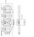
図1は実施形態の一例としてのストレージ装置1を備えるストレージシステム4のハードウェア構成を模式的に示す図、図2は実施形態の一例としてのストレージ装置1の機能構成を示す図である。
図1に例示するストレージシステム4においては、ストレージ装置1と1つ以上(図1に示す例では2つ)のホスト装置2a,2bとが冗長化された複数のパスを介して接続されている。FIG. 1 is a diagram schematically illustrating a hardware configuration of a
In the
ストレージ装置1は、ドライブエンクロージャ(DE:Drive Enclosure)30に格納された記憶装置31を仮想化して、仮想ストレージ環境を形成する。そしてストレージ装置1は、仮想ボリューム(LUN)を上位装置であるホスト装置2a,2bに提供する。
ホスト装置2a,2bは、例えば、サーバ機能をそなえた情報処理装置であり、本ストレージ装置1との間において、NAS(Network Attached Storage)やSAN(Storage Area Network)のコマンドを送受信する。これらのホスト装置2a,2bは、同様の構成を有している。The
The
以下、ホスト装置を示す符号としては、複数のホスト装置のうち1つを特定する必要があるときには符号2a,2bを用いるが、任意のホスト装置を指すときには符号2を用いる。
ホスト装置2は、図示しないCPU(Central Processing Unit)やメモリを備え、CPUがメモリ等に格納されたOS(Operating System)やプログラムを実行することで、種々の機能を実行する。Hereinafter, as a code indicating a host apparatus,
The
ホスト装置2は、例えば、ストレージ装置1に対してNASにおけるリード/ライト等のディスクアクセスコマンドを送信することにより、ストレージ装置1が提供するボリュームにデータの書き込みや読み出しを行なう。
そして、本ストレージ装置1は、ホスト装置2からボリュームに対して行なわれる入出力要求(例えば、リードコマンドやライトコマンド)に応じて、このボリュームに対応する実ストレージに対して、データの読み出しや書き込み等の処理を行なう。なお、ホスト装置2からの入出力要求のことをIOコマンドという場合がある。For example, the
Then, in response to an input / output request (for example, a read command or a write command) issued from the
スイッチ3a,3bは、ホスト装置2a,2bとストレージ装置1のコントローラ100との通信を中継する中継装置である。各スイッチ3a,3bは、それぞれホスト装置2a,2bに接続されるとともに、コントローラ100に接続されている。
図1に示す例においては、コントローラ100に2つのポート101a,101bが備えられている。そして、ポート101aにスイッチ3aが、又、ポート101bにスイッチ3bが、それぞれ接続され、更に、各スイッチ3a,3bにそれぞれホスト装置2a,2bが接続されている。The
In the example illustrated in FIG. 1, the
ストレージ装置1は、図1に示すように、1つ以上(本実施形態では1つ)のコントローラ100及び1つ以上(図1に示す例では1つ)のドライブエンクロージャ(DE)30をそなえる。
ドライブエンクロージャ30には、1以上(図1に示す例では8つ)の記憶装置(物理ディスク)31a−1〜31a−4,31b−1〜31b−4が搭載され、これらの記憶装置31a−1〜31a−4,31b−1〜31b−4の記憶領域(実ボリューム,実ストレージ)を、本ストレージ装置1に対して提供する。As illustrated in FIG. 1, the
One or more (eight in the example shown in FIG. 1) storage devices (physical disks) 31a-1 to 31a-4, 31b-1 to 31b-4 are mounted in the
以下、記憶装置を示す符号としては、複数の記憶装置のうち1つを特定する必要があるときには符号31a−1〜31a−4,31b−1〜31b−4を用いるが、任意の記憶装置を指すときには符号31を用いる。又、記憶装置31をディスク31という場合がある。
また、以下、記憶装置31a−1,31a−2,31a−3,31a−4を、disk1,disk2,disk3,disk4とそれぞれ表す場合がある。更に、以下、記憶装置31b−1,31b−2,31b−3,31b−4を、disk1’,disk2’,disk3’,disk4’とそれぞれ表す場合がある。Hereinafter, as reference numerals indicating storage devices,
Hereinafter, the
記憶装置31は、ハードディスクドライブ(HDD)、SSD等の記憶装置であって、種々のデータを格納するものである。
ドライブエンクロージャ30は、例えば複数段のスロット(図示省略)を備えて構成され、これらのスロットに記憶装置31を挿入することにより、実ボリューム容量を随時変更することができる。The storage device 31 is a storage device such as a hard disk drive (HDD) or SSD, and stores various data.
The
また、ドライブエンクロージャ30に備えられた複数の記憶装置31を用いてRAIDが構成される。図1に示す例においては、記憶装置31a−1〜31a−4を用いてRAIDが構成されており、これらの記憶装置31a−1〜31a−4がRAIDグループ30aを構成している。
このRAIDグループ30aを構成する記憶装置31a−1〜31a−4をRAID構成ディスク31aという場合がある。A RAID is configured using a plurality of storage devices 31 provided in the
The
記憶装置31b−1〜31b−4は、RAIDディスクグループ内のディスク故障にそなえて予備的に設けられた予備ディスクであり、ホットスペア(Hot spare;HS)として用いられる。これらの記憶装置31b−1〜31b−4が予備ディスクグループ30bを構成している。以下、記憶装置31bを予備ディスク31bという場合がある。
ドライブエンクロージャ30は、コントローラ100のデバイスアダプタ(Device Adapter:DA)103,103とそれぞれ接続されている。The
The
コントローラエンクロージャ40は、1以上(図1に示す例では1つ)のコントローラ100を備える。
コントローラ100は、ストレージ装置1内の動作を制御するストレージ制御装置であり、ホスト装置2から送信されるIOコマンドに従って、ドライブエンクロージャ30の記憶装置31へのアクセス制御等、各種制御を行なう。The
The
なお、図1に示す例においては、ストレージ装置1に1つのコントローラ100が備えられているが、これに限定されるものではなく、2つ以上のコントローラ100を備えてもよい。すなわち、複数のコントローラ100により冗長化を行ない、通常は、いずれかのコントローラ100がプライマリとして各種制御を行ない、このプライマリコントローラ100の故障時には、セカンダリのコントローラ100がプライマリとしての動作を引き継いでもよい。 In the example illustrated in FIG. 1, the
コントローラ100はポート101a,101bを介してホスト装置2に接続される。そして、コントローラ100は、ホスト装置2から送信されるリード/ライト等のIOコマンドを受信し、DA103等を介して記憶装置31の制御を行なう。
コントローラ100は、図1に示すように、ポート101a,101bと複数(図1に示す例では2つ)のDA103,103とをそなえるとともに、CPU110,メモリ106,フラッシュメモリ107及びIOC(Input Output Controller)108をそなえる。The
As shown in FIG. 1, the
以下、ポートを示す符号としては、複数のポートのうち1つを特定する必要があるときには符号101a,101bを用いるが、任意のポートを指すときには符号101を用いる。
ポート101は、ホスト装置2等から送信されたデータを受信したり、コントローラ100から出力するデータをホスト装置2等に送信する。すなわち、ポート101は、ホスト装置等の外部装置との間でのデータの入出力(IO)を制御する。Hereinafter, as a code indicating a port,
The port 101 receives data transmitted from the
ポート101aは、SANを介してホスト装置2と通信可能に接続され、例えば、FC(Fibre Channel)インタフェース等のネットワークアダプタに備えられるFCポートである。
ポート101bは、NASを介してホスト装置2と通信可能に接続され、例えば、LAN(Local Area Network)インタフェースのNIC(Network Interface Card)ポートである。コントローラ100は、これらのポート101により通信回線を介してホスト装置2等と接続され、IOコマンドの受信やデータの送受信等を行なう。The
The
そして、ポート101aにスイッチ3aが、又、ポート101bにスイッチ3bが、それぞれ接続され、更に、各スイッチ3a,3bにそれぞれホスト装置2a,2bが接続されている。
すなわち、ホスト装置2a,2bは、それぞれスイッチ3aを介してポート101aに接続されるとともに、スイッチ3bを介してポート101bに接続されている。The
That is, the
なお、図1に示す例においてはコントローラ100に2つのポート101a,101bが備えられているが、これに限定されるものではなく、1つもしくは3つ以上のポートを備えてもよい。
DA103は、ドライブエンクロージャ30や記憶装置31等と通信可能に接続するためのインタフェースである。DA103にはドライブエンクロージャ30の記憶装置31が接続され、コントローラ100は、ホスト装置2から受信したIOコマンドに基づき、これらの記憶装置31に対するアクセス制御を行なう。In the example shown in FIG. 1, the
The
コントローラ100は、これらのDA103を介して、記憶装置31に対するデータの書き込みや読み出しを行なう。又、図1に示す例においては、コントローラ100に2つのDA103がそなえられている。そして、コントローラ100において、各DA103にドライブエンクロージャ30が接続されている。これにより、ドライブエンクロージャ30の記憶装置31には、コントローラ100からデータの書き込みや読み出しを行なうことができる。 The
フラッシュメモリ107は、CPU110が実行するプログラムや種々のデータ等を格納する記憶装置である。
また、フラッシュメモリ107には、図2に示すように、ディスク情報67,リビルド時間情報68およびアクセス履歴データベース(DB:Data Base)66が格納される。
ディスク情報67は、本ストレージ装置1に備えられる各記憶装置31に関する情報である。このディスク情報67は、記憶装置31を特定する識別情報に対して、当該記憶装置31の性能情報を関連付けることにより構成されている。The
Further, as shown in FIG. 2, the
The
性能情報は、記憶装置31についての、リビルド処理に要する時間(リビルド時間)に影響を与える性能に関する情報である。性能情報は、特にデータアクセスに影響を与える性能を表すものであり、例えば、データ容量,モータの回転速度,RAID種別,SAS(Serial Attached Small Computer System Interface)/SATA(Serial AT Attachment)等のインタフェース種類,HDD/SSD等のディスク種類である。 The performance information is information regarding the performance that affects the time required for the rebuild process (rebuild time) for the storage device 31. The performance information expresses performance that particularly affects data access. For example, data capacity, motor rotation speed, RAID type, SAS (Serial Attached Small Computer System Interface) / SATA (Serial AT Attachment) interface, etc. Type, disk type such as HDD / SSD.
後述する情報取得部171等は、このディスク情報67を参照することで、リビルド先ディスク31bもしくはリビルド元ディスク31aの性能情報を取得する。
リビルド時間情報68は、記憶装置31に関して、リビルド処理に要する時間を示す。
図3は実施形態の一例としてのストレージ装置1におけるリビルド時間情報68を例示する図である。The
The
FIG. 3 is a diagram illustrating rebuild
この図3に例示するリビルド時間情報68は、記憶装置31の性能情報であるデータ容量及びモータの回転速度に対して、リビルド処理に要する時間(リビルド時間)を関連付けることにより構成されている。
リビルド時間には、例えば、運用実績に基づく実績値や期待値等が予め登録される。
なお、リビルド時間情報68は、これに限定されるものではなく、例えば、性能情報として上述したRAID種別やインタフェース種類,ディスク種類を関連付ける等、種々変形して実施することができる。The
For example, a performance value or an expected value based on the operation results is registered in advance as the rebuild time.
The
後述する第2決定部173は、リビルド先ディスク31b(もしくは故障ディスク31a)の性能情報に基づいて、このリビルド時間情報68を参照することでリビルド処理に要する時間を見積もり、予測リビルド時間を決定する。
アクセス履歴DB66は、後述するアクセス履歴作成部18によって作成されたアクセス履歴情報65(図6参照)を管理するデータベースである。このアクセス履歴DB66は、本ストレージ装置1において備えられる各LUN毎に作成された、所定時間毎のアクセス履歴であるアクセス履歴情報65を記録する。そして、例えば、日時やLUNを特定する識別情報等に基づいてこのアクセス履歴DB66を参照することで、任意のLUNについての任意の時間のアクセス履歴を取得することができる。The
The
また、このアクセス履歴DB66には、本ストレージシステム4に接続された他のストレージ装置のLUNについてのアクセス履歴情報も記録される。
メモリ106は、種々のデータやプログラムを一時的に格納する記憶装置であり、図示しないメモリ領域とキャッシュ領域とをそなえる。キャッシュ領域は、ホスト装置2から受信したデータや、ホスト装置2に対して送信するデータを一時的に格納する。メモリ領域には、CPU110がプログラムを実行する際に、データやプログラムを一時的に格納・展開して用いる。The
The
このメモリ106には、後述するRAID制御部12によるRAID制御に用いられる、仮/実ボリューム変換テーブル62やディスク構成情報63,RAID構成テーブル64等が格納される。仮/実ボリューム変換テーブル62は、ホスト装置2に提供する仮想ボリュームのアドレスを、記憶装置31の物理アドレス(実アドレス)にマッピングしているテーブルである。 The
ディスク構成情報63は、本ストレージ装置1に備えられる記憶装置31を管理する情報である。ディスク構成情報63において、例えば、各記憶装置31のディスク種別や、各記憶装置31がドライブエンクロージャ30のどのスロットに取り付けられているか、又、どの記憶装置31が予備ディスク31であるか等の情報が管理される。
RAID構成テーブル64は、後述するRAID制御部12がRAIDの管理を行なうために用いる情報であり、例えば、RAID種別や、RAIDグループ30aを構成する記憶装置31aを特定する情報等が格納される。The
The RAID configuration table 64 is information used by the
なお、これらの仮/実ボリューム変換テーブル62やディスク構成情報63,RAID構成テーブル64は既知であるので、その詳細な説明は省略する。
また、メモリ106には、後述するリビルド処理部13がリビルド処理を行なう際に、各リビルド元ディスク31aから読み出されたデータが一時的に格納される。
さらに、メモリ106には、LUN管理テーブル61及びアクセス履歴情報65c,65bが格納される。これらのLUN管理テーブル61及びアクセス履歴情報65c,65bの詳細は後述する。また、メモリ106には、後述するセッション情報も格納される。Since the temporary / real volume conversion table 62, the
Further, the
Further, the
IOC108は、コントローラ100内におけるデータ転送を制御する制御装置であり、例えば、メモリ106に格納されたデータをCPU110を介することなく転送させるDMA転送(Direct Memory Access)を実現する。
CPU110は、種々の制御や演算を行なう処理装置であり、例えばマルチコアプロセッサ(マルチCPU)である。CPU110は、フラッシュメモリ107等に格納されたOSやプログラムを実行することにより、種々の機能を実現する。The
The
図2に示すように、ストレージ装置1は、IO制御部11,RAID制御部12,リビルド処理部13,LUN選択部17,アクセス履歴作成部18及びコピー処理部19として機能する。
そして、コントローラ100のCPU110が、プログラム(ストレージ制御プログラム)を実行することにより、これらのIO制御部11,RAID制御部12,リビルド処理部13,LUN選択部17,アクセス履歴作成部18及びコピー処理部19として機能する。As illustrated in FIG. 2, the
Then, the
なお、これらのIO制御部11,RAID制御部12,リビルド処理部13,LUN選択部17,アクセス履歴作成部18及びコピー処理部19としての機能を実現するためのプログラム(ストレージ制御プログラム)は、例えばフレキシブルディスク,CD(CD−ROM,CD−R,CD−RW等),DVD(DVD−ROM,DVD−RAM,DVD−R,DVD+R,DVD−RW,DVD+RW,HD DVD等),ブルーレイディスク,磁気ディスク,光ディスク,光磁気ディスク等の、コンピュータ読取可能な記録媒体に記録された形態で提供される。そして、コンピュータはその記録媒体からプログラムを読み取って内部記憶装置または外部記憶装置に転送し格納して用いる。又、そのプログラムを、例えば磁気ディスク,光ディスク,光磁気ディスク等の記憶装置(記録媒体)に記録しておき、その記憶装置から通信経路を介してコンピュータに提供するようにしてもよい。 A program (storage control program) for realizing the functions as the
IO制御部11,RAID制御部12,リビルド処理部13,LUN選択部17,アクセス履歴作成部18及びコピー処理部19としての機能を実現する際には、内部記憶装置(本実施形態ではフラッシュメモリ107やメモリ106)に格納されたプログラムがコンピュータのマイクロプロセッサ(本実施形態ではCPU110)によって実行される。このとき、記録媒体に記録されたプログラムをコンピュータが読み取って実行するようにしてもよい。 When realizing functions as the
RAID制御部12は、記憶装置31aを用いてRAIDを実現し、RAIDを構成する記憶装置31aの制御を行なう。すなわち、RAID制御部12は、複数の記憶装置31aを用いた冗長構成を設定する。
このRAID制御部12は、上述したRAID構成テーブル64を作成・管理して、RAID構成ディスク31aを用いてRAIDグループ30aを設定し、各種RAID制御を行なう。なお、RAID制御部12によるRAIDの管理は既知の手法で実現することができ、その説明は省略する。The
The
また、RAID制御部12は、記憶装置31を用いてLUN(論理ボリューム)の設定・管理を行ない、ホスト装置2はこの設定されたLUNに対してデータアクセスを行なう。RAID制御部12は、LUN管理テーブル61を用いて、LUNの管理を行なう。すなわち、RAID制御部12は、LUNの管理を行なうLUN管理部としての機能を備える。 The
図4は実施形態の一例としてのストレージ装置1におけるLUN管理テーブル61の構成を例示する図である。
LUN管理テーブル61はLUN毎に備えられる管理情報であり、この図4に例示するLUN管理テーブル61はLUN1についての情報を示す。
LUN管理テーブル61は、項目と内容と備考とを関連付けて構成されている。図4に示す例においては、LUN管理テーブル61に12個の項目が登録されており、これらの項目を特定するための項番1〜12が設定されている。FIG. 4 is a diagram illustrating a configuration of the LUN management table 61 in the
The LUN management table 61 is management information provided for each LUN, and the LUN management table 61 illustrated in FIG. 4 shows information about LUN1.
The LUN management table 61 is configured by associating items, contents, and remarks. In the example shown in FIG. 4, twelve items are registered in the LUN management table 61, and
具体的には、項目として、LUN名,構成ディスク名リスト,各ディスク上の位置、サイズ,故障ディスク名,LUNの状態,利用予備ディスク名リスト,ディスクの安定度リスト,リビルド済サイズ,元ディスクのリード/ライト中カウンタ,予備ディスクのリード/ライト中カウンタ,元ディスクのIO禁止フラグ及び予備ディスクのIO禁止フラグが登録されており、これらに対して1〜12の項(項番)が設定されている。 Specifically, the items are LUN name, constituent disk name list, position on each disk, size, failed disk name, LUN status, spare disk name list used, disk stability list, rebuilt size, original disk The read / write counter, spare disk read / write counter, original disk IO prohibition flag, and spare disk IO prohibition flag are registered, and
項1のLUN名には、LUNを特定する識別情報が登録され、図4に示す例においては“LUN1”が登録されている。項2の構成ディスク名リストは、そのLUNを構成する記憶装置31を示す情報が登録される。すなわち、構成ディスク名リストには、RAID構成ディスク31aを示す情報が格納される。図4に示す例においては、構成ディスク名リストにdisk1,disk2,disk3,disk4が登録されている。 In the LUN name of
項3の各ディスク上の位置、サイズは、そのLUNを構成するRAID構成ディスク31a上における、当該LUNのデータの格納位置とサイズを示す情報が登録される。なお、位置としては、例えばオフセット(Offset)値が登録される。
項4の故障ディスク名は、そのLUNを構成するRAID構成ディスク31aにおいて、故障の発生が検知された記憶装置31aを示す情報が登録され、図4に示す例においては“disk2”が登録されている。As for the position and size on each disk in
For the failed disk name of
項5のLUNの状態は、そのLUNの状態を示す情報8が格納され、図4に示す例においては、正常な状態であることを示す“正常”、リビルド中であることを示す“rebuild中”及び、リビルド済みであることを示す“rebuild済”のいずれかが格納される。
項6の利用予備ディスク名リストは、各RAID構成ディスク31aに対応付けられている予備ディスク31bを示す情報が格納される。In the LUN state of
The used spare disk name list of Item 6 stores information indicating the
図4に示す例においては、項2の構成ディスク名リストのdisk1,disk2,disk3及びdisk4に対して、disk1’,disk2’,disk3’及びdisk4’が対応付けられている。すなわち、disk1とdisk1’とが対をなし、同様に、disk2,disk3及びdisk4がdisk2’,disk3’及びdisk4’とそれぞれ対をなす。
また、RAID構成ディスク31aの数に対して割り当て可能な予備ディスク31bの数(本数)が少ない場合には、一部のRAID構成ディスク31aに対してのみ予備ディスク31bが割り当てられる。図4においては、このように予備ディスク31bの数が少ない場合の例も表示されており、割り当てられた予備ディスク31bのみが示され、割り当てられる予備ディスク31bがない部分には、横線(−)を記している。In the example illustrated in FIG. 4, disk1 ′, disk2 ′, disk3 ′, and disk4 ′ are associated with disk1, disk2, disk3, and disk4 in the configuration disk name list of
In addition, when the number (number) of
項7のディスクの安定度リストには、そのLUNを構成するRAID構成ディスク31aを示す情報が、その安定度が高い順に登録される。図4に示す例においては、RAID構成ディスク31aが、disk1,disk4,disk3の順で登録されている。なお、disk2は故障中であるので、このディスクの安定度リストには登録されない。
項8のリビルド済サイズには、項2の故障ディスクに関するリビルド処理が実行された場合に、その復元されたデータの合計値(データサイズ)が進捗状況として登録される。このリビルド済みサイズの初期値は0であり、リビルド処理の進行に伴い、その値が大きくなる。In the disk stability list of item 7, information indicating the
When the rebuild process related to the failed disk of
例えば、上述した項3のLUNのサイズと、この項8のリビルド済サイズとを比較することにより、項5に格納されるLUNの状態として、“rebuild中”であるか“rebuild済”であるかを判断することができる。
項9の元ディスクのリード/ライト中カウンタには、そのLUNを構成する各RAID構成ディスク(元ディスク)31aのそれぞれについて、実行中のリードアクセス及びライトアクセスの数が格納される。すなわち、各RAID構成ディスク31aへのIOアクセス状態をリアルタイムに表す。For example, the LUN size stored in the
The read / write counter of the original disk of
図4に示す例においては、各RAID構成ディスク31aのそれぞれに対して、リード中カウンタの値nとライト中カウンタの値nとを、(n,n)の形式で示している。
ホスト装置2からLUNに対するリード要求もしくはライト要求のIOコマンドを受信すると、例えば、後述するIO制御部11が、そのアクセス先のRAID構成ディスク31aについてのリード中カウンタもしくはライト中カウンタの値をインクリメントする。又、IO制御部11は、リードアクセスもしくはライトアクセスが完了すると、対応するカウンタの値をデクリメントする。In the example shown in FIG. 4, the value n of the reading counter and the value n of the writing counter are shown in the form of (n, n) for each
When a read request or write request IO command for the LUN is received from the
この元ディスクのリード/ライト中カウンタの値を参照することで、各RAID構成ディスク31aがIO処理を実行中であるか否かを判断することができる。
項10の予備ディスクのリード/ライト中カウンタには、各予備ディスク31bのそれぞれについて、実行中のリードアクセス及びライトアクセスの数が格納される。すなわち、各予備ディスク31bへのIOアクセス状態を示す。By referring to the value of the reading / writing counter of the original disk, it can be determined whether or not each RAID-configured
In the spare disk read / write counter of
図4に示す例においては、各予備ディスク31bのそれぞれに対して、リード中カウンタの値nとライト中カウンタの値nとを、(n,n)の形式で示している。
例えば、その予備ディスク31bに対してデータのライトを行なう際にライト中カウンタの値がインクリメントされる。又、ライト処理が完了すると、対応するカウンタの値はデクリメントされる。In the example shown in FIG. 4, the value n of the reading counter and the value n of the writing counter are shown in the form of (n, n) for each
For example, the value of the writing counter is incremented when data is written to the
この予備ディスクのリード/ライト中カウンタの値を参照することで、各予備ディスク31bがIO処理を実行中であるか否かを判断することができる。
項11の元ディスクのIO禁止フラグは、そのLUNを構成する各RAID構成ディスク31aのそれぞれについて、IO処理が禁止されているか否かを示す情報が格納される。図4に示す例においては、“0”もしくは“1”が格納され、“1”がフラグとして設定されている場合には、そのRAID構成ディスク31aへのIOが禁止されていることを示す。By referring to the value of the spare disk read / write counter, it is possible to determine whether or not each
The original disk IO prohibition flag of
項12の予備ディスクのIO禁止フラグは、予備ディスク31bのそれぞれについて、IO処理が禁止されているか否かを示す情報が格納される。図4に示す例においては、“0”もしくは“1”が格納され、“1”がフラグとして設定されている場合には、その予備ディスク31bへのIOが禁止されていることを示す。
コピー処理部19は、LUN(コピー元LUN)に記憶されたデータのコピーを、他のLUN(コピー先LUN)に転送し、このコピー先のLUNに格納することにより、データのバックアップを行なう。In the spare disk IO prohibition flag of
The
本実施形態において、コピー処理部19は、コピー元LUNからコピー先LUNへのデータ転送を、例えばOPC(One Point Copy)を用いて行なう。OPCとは、バックアップ対象となるデータについて所定時点における、その後の更新等を含まないデータであるスナップショット(Snapshot)を作成するものである。具体的には、バックアップを作成する際に、当該作成時点における対象となるコピー元LUN(ボリューム)の全データをバックアップする手法である。 In the present embodiment, the
なお、コピー処理部19によるコピー元LUNからコピー先LUNへのバックアップ手法は、OPCに限定されるものではなく種々の手法を用いて実現してもよい。例えば、バックアップ手法として、OPCの拡張機能としての、SnapOPC,SnapOPC+,QuickOPC等の手法を用いて行なってもよく、また、他のデータバックアップ手法を用いてもよい。 Note that the backup method from the copy source LUN to the copy destination LUN by the
なお、これらのOPC,SnapOPC,SnapOPC+,QuickOPC等によるコピー元LUNからコピー先LUNへのデータのバックアップ手法は既知であり、その詳細な説明は省略する。
以下、コピー処理部19が、コピー元LUNからコピー先LUNへのデータ転送をOPCの手法を用いて行なう例について示す。The data backup method from the copy source LUN to the copy destination LUN by these OPC, SnapOPC, SnapOPC +, QuickOPC, etc. is known, and detailed description thereof is omitted.
Hereinafter, an example in which the
1回のOPC等のコピーの処理の単位をセッションという。以下、コピー元のボリュームからコピー先のボリュームへのデータのコピー処理をコピーセッションもしくは単にセッションという場合がある。
コピー処理部19は、例えば、セッション情報(図示省略)を用いて、コピーセッションに関する情報を管理する。A unit of copy processing such as one OPC is called a session. Hereinafter, data copy processing from a copy source volume to a copy destination volume may be referred to as a copy session or simply a session.
The
セッション情報は、コピーセッションに関する情報であって、例えば、セッションID(Session ID),コピー元LUN(Logical Unit Number)及び開始LBA(Logical Block Address),コピー先LUN及び開始LBA及びBC(Block Count)並びにコピー種別である。このようなセッション情報は、例えば、メモリ106の所定の領域に格納される。なお、セッション情報は既知であり、その詳細な説明は省略する。 The session information is information related to the copy session. For example, the session ID (Session ID), the copy source LUN (Logical Unit Number) and the start LBA (Logical Block Address), the copy destination LUN, the start LBA, and BC (Block Count). And the copy type. Such session information is stored in a predetermined area of the
後述する情報取得部171は、このセッション情報を参照することで、OPCのコピーセッションについて、そのコピー元LUN及びコピー先LUNを把握することができる。
リビルド処理部13は、例えば、いずれかのディスク31aの故障を検出した場合に、リビルド処理を実行制御する。以下、故障が検出されたディスク31aを故障ディスク31aという場合がある。この故障ディスク31aが復元対象記憶装置に相当する。なお、ディスク31aの故障は、例えば媒体エラー等の所定のエラーが閾値として設定された頻度以上で生じる場合に発生したと判断される。The
For example, the
リビルド処理は、RAIDグループの冗長性を自動回復する処理であり、RAIDグループに属する記憶装置31aが故障した際に、代理として用いられる予備ディスク(代理ディスク,第1の予備記憶装置,復元先記憶装置)31bに対し、故障ディスク31aのデータを、同一RAIDグループにおける故障ディスク31a以外の記憶装置31aのデータを用いて再構築する処理である。以下、同一RAIDグループにおける故障ディスク31a以外の記憶装置(冗長用記憶装置)31aをリビルド元ディスク31aという場合がある。又、このリビルド元ディスクを単に元ディスクという場合もある。 The rebuild process is a process for automatically recovering the redundancy of the RAID group. When the
つまり、リビルド処理部13は、故障ディスク31aの発生を検出すると、故障ディスク31a以外のリビルド元ディスク31aのデータ(復元用データ)を用いて、故障ディスク31aに代わる代理ディスク(リビルド先ディスク)31bに故障ディスク31aのデータを再構築する。
このように、リビルド処理部13は、複数のRAID構成ディスク31aのうち故障ディスク(復元対象記憶装置)31a以外のリビルド元ディスク(冗長用記憶装置)31aから読み出した冗長データを用いて、故障ディスク31aのデータを、予備ディスク(第1の予備記憶装置,復元先記憶装置)に再構成(復元)する復元部として機能する。That is, when the
As described above, the
リビルド処理部13による故障ディスク31aのデータの復元は、既知の手法で実現することができる。
同一のRAIDグループ30aを構成する複数の記憶装置31aは、各記憶装置31aのデータが他の複数の記憶装置(冗長用記憶装置)31aに分散してコピーされることにより、冗長化されている。The restoration of the failed
A plurality of
リビルド処理部13は、故障ディスク31aと同じRAIDグループを構成する複数の記憶装置(冗長用記憶装置)31aにそれぞれ格納された復元用データを読み出して、代替ディスク31bに格納することで、故障ディスク31aのデータを代替ディスク31bに復元(データディスク構築)する。
例えば、メモリ106の所定の領域に、格納した故障ディスク31a以外の各リビルド元ディスク31aから読み出したデータを格納し、このデータに対してパリティを用いたXOR(排他的論理和)演算を行なうことで、故障ディスク31aのデータの復元を行なう。The
For example, data read from each rebuilding
図5は実施形態の一例としてのストレージ装置1におけるリビルド処理を説明する図である。この図5に示す例においては、RAIDグループ30aは、4本(3本+1本)のRAID構成ディスク31a−1〜31a−4によりRAID5を実現している。
以下、本実施形態においては、これらのRAID構成ディスク31a−1〜31a−4のうち、ディスク31a−2の故障が検知された場合を示す。すなわち、RAIDグループ30aにおいてディスク31a−2の故障が発生したものとし、以下、この故障が発生しているRAIDグループ30aを故障RAIDグループ30aという場合がある。FIG. 5 is a diagram illustrating rebuild processing in the
Hereinafter, in the present embodiment, a case where a failure of the
また、この図5に示す例においては、RAIDグループ30aのディスク31a−1〜31a−4を用いて3つのLUN1〜3が形成されており、これらのうちLUN1のデータ(Data1-2)を復元する例を示している。
リビルド処理部13は、ディスク31a−2の故障を検出すると、同一RAIDグループ30a内のリビルド元ディスク31a−1,31a−3,31a−4の復元用データ(Data1-1,1-3,1-4)を用いて、故障ディスク31a−2のLUN1のデータ(復元Date1-2)を作成する(図5中の破線参照)。Further, in the example shown in FIG. 5, three
When the
そして、この作成した故障ディスク31a−2のLUN1のデータ(復元Date1-2)を、故障ディスク31a−2に代わる代替ディスク(リビルド先ディスク)31b−2に格納することで、LUN1のデータを復元し、故障ディスク31a−2を再構築する。
RAIDグループ30aにおいて、複数のLUNが形成されている場合には、リビルド処理部13はLUN毎にリビルド処理を行なう。The LUN1 data is restored by storing the created LUN1 data (restore Date1-2) of the failed
When a plurality of LUNs are formed in the
また、リビルド処理部13は、RAIDグループ30aにおいて複数のLUNが形成されている場合には、LUN選択部17によって設定された順番(優先順位)に従って、複数のLUNを順番にリビルドする。すなわち、LUN選択部17によって選択されたLUN(優先LUN;優先論理ボリューム)を優先してリビルド処理を行なう。
また、リビルド処理部13は、複数のLUNについてリビルドを行なう場合には、これらの複数のLUNの一覧(図示省略)と、当該一覧においてリビルド処理の進捗を示すポインタとを用いて、リビルド処理の進捗状況を管理する。In addition, when a plurality of LUNs are formed in the
In addition, when rebuilding a plurality of LUNs, the
アクセス履歴作成部18は、RAID制御部12によって管理される各LUNに対するアクセス履歴を採取し、アクセス履歴情報65(図6参照)を作成する。
具体的には、アクセス履歴作成部18は、各LUNに対するライトアクセスおよびリードアクセスをそれぞれ図示しないカウンタ(アクセスカウンタ)を用いて計数し、そのカウント値をアクセス履歴情報65cに記録する。The access
Specifically, the access
図6は実施形態の一例としてのストレージ装置1におけるアクセス履歴情報65cの構成を例示する図である。
この図6に示す例においては、本ストレージ装置1において管理されるLUN(L1〜L6)のそれぞれに対して、計数されたリードのアクセス数とライトのアクセス数とが対応付けられている。また、リードのアクセスに関しては、ランダムリード回数とシーケンシャルリード回数とが管理されており、ライトのアクセスに関しても、ランダムライト回数とシーケンシャルライト回数とが管理されている。FIG. 6 is a diagram illustrating a configuration of the
In the example shown in FIG. 6, the number of read accesses and the number of write accesses are associated with each of the LUNs (L1 to L6) managed in the
すなわち、アクセス履歴作成部18は、ランダムリード回数,シーケンシャルリード回数,ランダムライト回数及びシーケンシャルライト回数を、アクセス履歴情報65cを用いて管理する。そして、アクセス履歴作成部18は、LUNに対してリードアクセスやライトアクセスが発生すると、対応するカウンタ値を更新する。
また、アクセス履歴作成部18は、所定期間(例えば、1時間)が経過する毎に、作成したアクセス履歴情報65cを、フラッシュメモリ107のアクセス履歴DB66に、当該アクセス履歴情報65cに関する日付や時刻の情報(タイムスタンプ)とともに記録する。That is, the access
Further, the access
なお、アクセス履歴情報65cに関する日時情報は、当該アクセス履歴情報65cを作成した日時であってもよく、当該アクセス履歴情報65cをアクセス履歴DB66に記録した日時であってもよく、種々変形して実施することができる。
これにより、アクセス履歴DB66には、所定期間毎に作成されたアクセス履歴情報65cがデータ採取時刻の情報とともにエントリとして蓄積される。The date / time information related to the
Thereby, in the
以下、上記所定期間、すなわち、先にアクセス履歴情報65cがアクセス履歴DB66に記録されてから、次にアクセス履歴情報65cがアクセス履歴DB66に記録されるまでの期間を、アクセス履歴採取期間という場合がある。本実施形態においては、アクセス履歴採取期間が1時間である例について示す。
すなわち、アクセス履歴情報65cにおけるランダムリード回数,シーケンシャルリード回数,ランダムライト回数及びシーケンシャルライト回数の各値は、“回数/1時間”の単位で表される。Hereinafter, the predetermined period, that is, the period from when the
That is, each value of the random read count, sequential read count, random write count, and sequential write count in the
また、アクセス履歴作成部18は、上記アクセス履歴採取期間が経過するタイミング、つまり、アクセス履歴情報65cをアクセス履歴DB66に記録するタイミングで、メモリ106における所定の記憶領域に、先に作成したアクセス履歴情報65cをアクセス履歴情報65bとして記録(複写)する。また、これに伴い、メモリ106において、先にアクセス履歴情報65bとして記録されていた情報は破棄される。 The access
すなわち、メモリ106において、先に作成されていたアクセス履歴情報65bは、アクセス履歴情報65cにより上書き更新される。以下、アクセス履歴情報65bをアクセス履歴情報65cにより上書き更新することを、アクセス履歴情報65bを更新するという場合がある。
さらに、アクセス履歴作成部18は、アクセス履歴情報65bをアクセス履歴情報65cにより上書き更新した後に、アクセス履歴情報65cをリセットする。リセットされたアクセス履歴情報65cにおいては、それ以降のLUNに対するアクセス発生時に、アクセス履歴作成部18により対応するカウンタ値が更新される。That is, the
Further, the access
すなわち、アクセス履歴情報65cには、アクセス履歴採取期間に各LUNに対して行なわれたリード/ライトアクセス回数が記録される。このアクセス履歴情報65cは、各LUNに対する最新のアクセス履歴を示すものであり、以下、アクセス履歴情報65cを、カレントのアクセス履歴情報65cという場合がある。
一方、アクセス履歴情報65bには、カレントのアクセス履歴情報65cよりも1つ前、すなわち、1世代前に採取されたアクセス履歴が記録される。That is, the
On the other hand, in the
したがって、メモリ106には、カレントのアクセス履歴情報65cと、その1つ前の世代のアクセス履歴情報65bとの2世代分のアクセス履歴が格納されることになる。
また、アクセス履歴情報65cとアクセス履歴情報65bとは、図5に示すような同様の構成を備える。
以下、アクセス履歴情報というときは、符号65cで示すカレントのアクセス履歴情報のほか符号65bで示す1世代前のアクセス履歴情報も含むが、代表してアクセス履歴情報65として表記する場合もある。Accordingly, the access history for two generations of the current
Further, the
Hereinafter, the access history information includes not only the current access history information indicated by
また、アクセス履歴情報65cはフラッシュメモリ107のアクセス履歴DB66に記録される。 すなわち、アクセス履歴DB66はアクセス履歴情報65の集合として構成される。これにより、アクセス履歴DB66をLUNに対して行なわれたアクセスの統計情報として用いることができる。例えば、後述するリビルド時間予測部173が、アクセス履歴DB66を日時や曜日等をキーに検索することで、任意のLUNについて所定の時間帯でのアクセス実績(アクセス履歴)を参照することができる。 The
図7は実施形態の一例としてのストレージ装置1におけるアクセス履歴情報65の作成方法を例示するフローチャート(ステップS01〜S06)である。
本処理は、ホスト装置2からLUNに対するライトアクセスもしくはリードアクセスを受信する毎に実行される。
ホスト装置2からライトアクセスもしくはリードアクセス処理要求を受信すると、この処理要求に応じて、後述するIO制御部11がLUNに対するIO制御を行なう(ステップS01)。FIG. 7 is a flowchart (steps S01 to S06) illustrating a method for creating the
This process is executed each time a write access or read access to the LUN is received from the
When a write access or read access processing request is received from the
ステップS02において、アクセス履歴作成部18は、アクセス履歴情報65cにおいて、対応するアクセス種類に対して、アクセス対象のLUNに対応するカウンタの値を更新する。
ステップS03において、アクセス履歴作成部18は現時刻の“分”および“秒”を確認する。すなわち、現時刻が0分0秒であるかを確認する(ステップS04)。これにより、アクセス履歴採取期間である1時間が経過したか否かを確認するのである。In step S02, the access
In step S03, the access
確認の結果、0分0秒である場合には(ステップS04のYesルート参照)、ステップS05において、カレントのアクセス履歴情報65cを日付や時刻の情報とともにアクセス履歴DB66に記録する。
また、ステップS06において、メモリ106において、アクセス履歴情報65bをアクセス履歴情報65cにより上書き更新するとともに、アクセス履歴情報65cをリセットし、処理を終了する。As a result of the confirmation, if it is 0
In step S06, the
一方、ステップS04における確認の結果、0分0秒でない場合(ステップS04のNoルート参照)、処理を終了する。
LUN選択部17は、アクセス履歴作成部18によって作成されたアクセス履歴情報65に基づき、故障RAIDグループ30aにおいて形成されている複数のLUNに対して、リビルド処理(復元処理)が行なわれる順番(優先順位)、すなわち、リビルド処理順序を設定する。また、以下、リビルド処理順序をLUN順番という場合がある。On the other hand, if the result of the confirmation in step S04 is not 0
Based on the
すなわち、LUN選択部17は、アクセス履歴作成部18によって作成されたアクセス履歴情報65に基づき、複数のLUNのうち、優先してリビルド処理を行なう優先LUNを決定する。
また、LUN選択部17は、リビルド処理順序の決定方法として、第1決定部172(後述)による第1の優先順位設定方法と、第2決定部173(後述)による第2の優先順位決定方法とを備える。In other words, the
The
なお、第1の優先順位設定方法と第2の優先順位設定方法とのいずれを採用するかは、例えば、ユーザがGUI(Graphical User Interface)を介して入力を行なうことで選択され、その入力結果が設定値としてフラッシュメモリ107等の所定の記憶領域に記憶される。また、第1の優先順位設定方法もしくは第2の優先順位設定方法のいずれを採用するかを予め設定情報として登録してもよい。 Note that whether the first priority setting method or the second priority setting method is adopted is selected by, for example, the user performing input via a GUI (Graphical User Interface), and the input result Is stored in a predetermined storage area such as the
すなわち、LUN選択部17(第1決定部172,第2決定部173)は、アクセス履歴取得部171によって取得されたアクセス履歴情報65に基づき、故障RAIDグループ30aを構成する複数のLUNのうち、優先して復元処理(リビルド処理)を行なう優先論理ボリュームを決定する論理ボリューム決定部として機能する。
また、LUN選択部17(第1決定部172,第2決定部173)は、上述したアクセス履歴情報65に基づき、故障RAIDグループ30aを構成する複数のLUNのうち、重要度が高いと判断されるLUNを優先LUNとして決定する。That is, the LUN selection unit 17 (
Further, the LUN selection unit 17 (the
LUN選択部17は、図2に示すように、情報取得部171,第1決定部172,第2決定部173としての機能を備える。
情報取得部171は、後述する第1決定部172および第2決定部173がリビルド処理を行なうLUNの優先順位を決定するために用いる各種情報を取得する。
例えば、情報取得部171は、RAIDグループ30aにおいていずれかのRAID構成ディスク31aに異常が検知されると、この故障RAIDグループ30a上で形成されているLUNの情報を取得する。As shown in FIG. 2, the
The
For example, when an abnormality is detected in any
例えば、情報取得部171は、LUN管理テーブル61を参照することで、故障RAIDグループ30a上で形成されているLUN名を取得する。LUN管理テーブル61はLUN毎に作成されるので、例えば、各LUN管理テーブル61の項1を参照することで、RAIDグループ30aに形成されているLUNを把握することができる。
情報取得部171は、故障RAIDグループ30a上に形成されているLUNをリストアップし、例えば、メモリ106の所定の領域に格納する。For example, the
The
また、情報取得部171は、第1決定部172による第1の優先順位設定方法に用いられる以下の情報を取得する。LUNの重要度に基づきリビルド処理順序を決定する場合に、この第1の優先順位設定方法が用いられる。
すなわち、情報取得部171は、上述の如くリストアップした各LUNに基づき、前述したセッション情報を参照することで、各LUNのOPCにおける関係性を取得する。具体的には、情報取得部171は、リストアップされた各LUNについて、OPCのコピー元LUNもしくはコピー先LUNとなっているか否かをそれぞれ確認する。In addition, the
That is, the
さらに、情報取得部171は、OPCのコピー元となっているLUNについて、セッション情報を参照することで、そのコピー先LUNを確認し、更に、アクセス履歴DB66を参照して、このコピー先LUNに関するアクセス履歴情報65を取得する。
また、情報取得部171は、アクセス履歴DB66を参照して、上述したリストアップされたLUNにおいて、OPCのコピー元LUNおよびコピー先LUNのいずれにもなっていないLUNのアクセス履歴情報65も取得する。Further, the
Also, the
また、情報取得部171は、第2決定部173による第2の優先順位設定方法に用いられる以下の情報を取得する。本ストレージ装置1が使用される時間帯を考慮したリビルド処理順序を決定する場合に、この第2の優先順位設定方法が用いられる。
すなわち、情報取得部171は、ディスク情報67を参照して、故障RAIDグループ30aを構成する各記憶装置31の性能情報を収集する。In addition, the
In other words, the
また、情報取得部171は、収集した記憶装置31の性能情報に基づいてリビルド時間情報68を参照して、その記憶装置31の性能情報に相当するリビルド時間を取得する。
さらに、情報取得部171は、アクセス履歴DB66を参照して、上述したリストアップされた各LUNのアクセス履歴情報65も取得する。
[第1の優先順位設定方法について]
第1決定部172は、第1の優先順位設定方法によりリビルド処理を行なうLUNの順番(リビルド処理順序)を決定する。Further, the
Further, the
[First priority setting method]
The
この第1の優先順位設定方法においては、第1決定部172は、以下の優先順位に従ってリビルド処理順序を設定する。
優先順位1:OPC対象のLUN(OPC元LUN)で、OPC先にシーケンシャルリードが発生しているLUN。
優先順位2:OPC対象のLUN(OPC元LUN)
優先順位3:異常検知時よりも前の所定時間帯に行なわれたアクセス回数が多いLUN
優先順位4:OPC先のLUN
(1)優先順位1について
第1の優先順位設定方法においては、第1決定部172は、OPCのコピー元となっているLUNであって、そのコピー先LUNにシーケンシャルリードアクセスが発生しているものを、リビルド処理の優先度の高いものとして決定する。In the first priority order setting method, the
Priority 1: LUN with OPC target LUN (OPC source LUN) in which sequential read is generated at the OPC destination.
Priority 2: LUN targeted for OPC (OPC source LUN)
Priority 3: LUN with a large number of accesses made in a predetermined time zone before the time of abnormality detection
Priority 4: LUN of OPC destination
(1)
ここで、シーケンシャルリードアクセスとは、所定の閾値以上連続するデータが順番に読み出されることをいう。
すなわち、第1の優先順位設定方法においては、所謂D2D2T(Disk to Disk to Tape)のバックアップ構成がされているコピー元LUNをリビルド処理の優先順位が高いものとして設定する。Here, the sequential read access means that data that is continuous over a predetermined threshold is read in order.
In other words, in the first priority order setting method, a copy source LUN having a so-called D2D2T (Disk to Disk to Tape) backup configuration is set with a high priority of rebuild processing.
図8は実施形態の一例としてのストレージ装置1における第1決定部172による第1の優先順位設定方法について説明するための図である。
この図8においては、D2D2Tの構成を例示している。すなわち、コピー元LUN(OPC元LUN)のデータはコピー先LUN(OPC先LUN)にバックアップされた後、更に、LT(Linear Tape)にバックアップされている。FIG. 8 is a diagram for explaining a first priority setting method by the
FIG. 8 illustrates the configuration of D2D2T. That is, the data of the copy source LUN (OPC source LUN) is backed up to a copy destination LUN (OPC destination LUN) and then backed up to an LT (Linear Tape).
このように、LUN(ディスクドライブ)とLTとの2段階のバックアップがとられるデータはユーザにとって重要なデータであると考えられる。そこで、第1決定部172は、D2D2Tのバックアップ構成がされているコピー元LUNをリビルド処理の優先順位が高いものとして決定する。
LTにバックアップコピーを行なう場合には、図8に示すように、LTへ書き出すデータを読み出すためにコピー先LUNにシーケンシャルなリードアクセスが発生する。そこで、第1決定部172は、OPCのコピー元となっているLUNであって、そのコピー先LUNにシーケンシャルリードアクセスが発生しているもののリビルド処理の優先順位を最も高く設定する。As described above, the data that is backed up in two stages of LUN (disk drive) and LT is considered to be important data for the user. Therefore, the
When performing backup copy to the LT, as shown in FIG. 8, sequential read access occurs to the copy destination LUN in order to read data to be written to the LT. Therefore, the
また、このような、OPCコピーがされているコピー元LUNであって、そのOPC先であるコピー先LUNにシーケンシャルリードが発生しているものが複数ある場合には、これらの複数の優先LUN間においても優先順位を設定する。
例えば、第1決定部172は、これらの複数のコピー元LUNについて、各OPC先であるコピー先LUNをシーケンシャルリードの回数が多い順に順位付けし、その順位に応じて、各コピー元LUNに優先順位を設定する。つまり、OPC先であるコピー先LUNにおいてシーケンシャルリードの回数が多いコピー元LUNの優先順位を高く設定する。In addition, when there are a plurality of copy source LUNs that have been subjected to OPC copying, and the copy destination LUN that is the OPC destination has a sequential read, between the plurality of priority LUNs. The priority order is also set at.
For example, the
なお、本実施形態において、第1決定部172は、優先順位1として、OPCのコピー元となっているLUNであって、そのコピー先LUNにシーケンシャルリードアクセスが発生しているもののリビルド処理の優先順位を最も高く設定しているが、これに限定されるものではない。
例えば、OPC対象のLUNで、OPC先に特定の時間にシーケンシャルリードがされているLUNの優先順位を特に高くしてもよい。これにより、定期的なテープバックアップが行なわれているような重要なコピー元LUNをより確実に特定することができる。In the present embodiment, the
For example, the priority order of LUNs that are sequentially read at a specific time at the OPC destination in the LUN targeted for OPC may be made particularly high. As a result, it is possible to more reliably identify an important copy source LUN for which regular tape backup is performed.
また、OPCのコピー元となっているLUNであって、そのコピー先LUNにシーケンシャルリードアクセスが所定の閾値よりも多く発生しているものリビルド処理の優先順位を最も高く設定してもよい。
すなわち、第1決定部172は、OPCコピーがされているコピー元LUNであって、そのOPC先であるコピー先LUNに閾値以上の回数のリード(シーケンシャルリード)が発生しているものを優先LUNとして決定してもよい。Alternatively, the priority of the rebuild process may be set to the highest as the LUN that is the copy source of the OPC and in which the sequential read access occurs more than a predetermined threshold in the copy destination LUN.
That is, the
なお、このような、OPCコピーがされているコピー元LUNであって、そのOPC先であるコピー先LUNに閾値以上の回数のシーケンシャルリードが発生しているものが複数ある場合にも、OPC先であるコピー先LUNにおいてシーケンシャルリードの回数が多いコピー元LUNの優先順位を高く設定することが望ましい。
(2)優先順位2について
また、LTへのバックアップは行なわれていないがOPCによるバックアップは行なわれているLUN(コピー元LUN)は、ユーザにとって少なくとも1回はバックアップする必要性があると判断されているデータであると考えられる。そこで、第1決定部172は、LTへのバックアップは行なわれていないがOPCによるバックアップは行なわれているコピー元LUN(OPC対象のLUN)のリビルド処理の優先順位を2番目に高く設定する。It should be noted that even when there are a plurality of copy source LUNs that have been subjected to OPC copying, and the copy destination LUN that is the OPC destination has undergone sequential read more than the threshold value, the OPC destination It is desirable to set a higher priority for the copy source LUN having a large number of sequential reads in the copy destination LUN.
(2)
(3)優先順位4について
一方、OPC先LUNは、バックアップ先であり冗長化されていると考えられ、そのデータの重要度は低いと判断できる。そこで第1決定部172は、このようなOPC先LUNのリビルド処理の優先順位を最も低く設定する。
(4)優先順位3について
上述した優先順位1,2,4のいずれにも該当しないLUNについては、アクセス履歴が多いものから順番にリビルド処理の優先順位を設定する。例えば、第1決定部172は、メモリ106に格納されているアクセス履歴情報65c,65bを参照して、これらのアクセス履歴情報65においてアクセス回数が多いLUNから順番にリビルド処理の優先順位を設定する。なお、ここで言うアクセス回数とは、例えば、ランダムリード回数,シーケンシャルリード回数,ランダムライト回数及びシーケンシャルライト回数の合計である。(3)
(4)
前述の如く、メモリ106に格納されているアクセス履歴情報65c,65bには、故障ディスク31aにおいて異常が検知された時点よりも前の所定の時間帯に行なわれた2世代分のアクセス履歴が格納されている。
すなわち、第1決定部172は、復元対象記憶装置である故障ディスク31aにおける異常検知時よりも前の所定時間帯(例えば、2時間)に採取されたアクセス履歴に基づき、これらの所定時間帯でのアクセス回数が多いLUNを、優先LUNとして決定する。As described above, the
In other words, the
データアクセスが高速なメモリ106に格納されているアクセス履歴情報65に基づいてリビルド処理の優先順位を設定することで、LUNの優先順位を短時間で決定することができる。
以上の手法により、第1決定部172は、RAID構成ディスク31aに形成された複数のLUNに対するリビルド処理順序を決定する。By setting the rebuild processing priority based on the
With the above method, the
[第2の優先順位設定方法について]
第2決定部173は、第2の優先順位設定方法によりリビルド処理を行なうLUNの順番(リビルド処理順序)を決定する。
この第2の優先順位設定方法においては、第2決定部173は、リビルド先ディスク(復元先記憶装置)31bへのリビルド処理に要する時間を見積もる。そして、第2決定部173は、リビルド処理部13により故障ディスク(復元対象記憶装置)31aのリビルドが行なわれる時間帯(予測リビルド時間帯)を予測する
すなわち、第2決定部173は、リビルド処理部13により故障ディスク(復元対象記憶装置)31aのリビルドが行なわれる時間帯を予測する復元時間帯予測部として機能する。[Second priority setting method]
The
In the second priority setting method, the
具体的には、第2決定部173は、情報取得部171がリビルド先ディスク31b(故障ディスク31a)の性能情報(仕様)に基づいてリビルド時間情報68から取得したリビルド時間を、リビルド先ディスク31bへのリビルドに要する時間(予測リビルド時間)とみなす(見積もる)。
そして、第2決定部173は、リビルド開始予定時刻と予測リビルド時間とに基づいて予測リビルド時間帯を決定する。すなわち、第2決定部173は、リビルド開始予定時刻から予測リビルド時間が経過するまでの期間を予測リビルド時間帯として決定する。Specifically, the
Then, the
そして、第2決定部173は、アクセス履歴DB66に基づいて、この決定した予測リビルド時間帯、すなわち、リビルド開始予定時刻からリビルド完了予測時刻までの時間帯と同時間帯での各LUNのアクセス実績に応じて各LUNへのリビルド処理の優先順位を設定する。
なお、一般に、リビルド先ディスク31bとしては故障ディスク31aと同じ種類の記憶装置を用いる。従って、本実施形態においては、リビルド先ディスク31bの性能情報と故障ディスク31aの性能情報とは一致するものとする。Based on the
In general, the same type of storage device as that of the failed
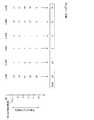
図9は実施形態の一例としてのストレージ装置1における第2決定部173による第2の優先順位設定方法について説明するための図である。
この図9に示す例においては、リビルド処理の開始時刻が7時であり、第2決定部(復元予測部)173が予測リビルド時間を5時間と予測した場合の例を示す。この場合、予測リビルド時間帯は7時〜12時である。FIG. 9 is a diagram for explaining a second priority setting method by the
In the example illustrated in FIG. 9, an example is shown in which the rebuild process start time is 7:00 and the second determination unit (restoration prediction unit) 173 predicts the predicted rebuild time as 5 hours. In this case, the predicted rebuilding time zone is from 7:00 to 12:00.
本例においては、LUN1〜6のそれぞれについて、7時〜12時の時間帯(期間)における時間毎のアクセス回数小計を示している。
ここで、アクセス回数小計とは、ランダムリード回数,シーケンシャルリード回数,ランダムライト回数及びシーケンシャルライト回数の合計である。これらの値は、情報取得部171によりアクセス履歴DB66から取得される。In this example, for each of the
Here, the access count subtotal is the total of the random read count, sequential read count, random write count, and sequential write count. These values are acquired from the
例えば、7時代においては、LUN1に対するアクセス回数小計は10×10^10(単位:回)であり、LUN2に対するアクセス回数小計は1×10^10(単位:回)である。
また、第2決定部173は、各LUNについて、予測リビルド時間帯におけるアクセス回数小計の合計をそれぞれ算出する。
例えば、図9に示す例において、LUN1についての7時〜12時の各時間でのアクセス回数小計の合計(SUM)は83×10^10(単位:回)であり、LUN2については24×10^10(単位:回)である。すなわち、本ストレージ装置1においては、予測リビルド時間帯である7時〜12時の時間帯では、LUN1,LUN6,LUN5,LUN2,LUN4,LUN3の順でアクセスが多いことが統計的に判明する。従って、予測リビルド時間帯においても、LUN1,LUN6,LUN5,LUN2,LUN4,LUN3の順でアクセスが発生する可能性が高いと考えられる。For example, in the 7th era, the access count subtotal for LUN1 is 10 × 10 ^ 10 (unit: times), and the access count subtotal for LUN2 is 1 × 10 ^ 10 (unit: times).
In addition, the
For example, in the example shown in FIG. 9, the total (SUM) of the number of times of access for each time from 7:00 to 12:00 for LUN1 is 83 × 10 ^ 10 (unit: times), and for LUN2 is 24 × 10 ^ 10 (unit: times). That is, in this
そこで、第2決定部173は、過去のアクセス実績の統計情報に基づき、予測リビルド時間帯においてアクセス回数が多いLUNをリビルド処理の優先順位が高いものとして設定する。第2決定部173は、このような過去のアクセス実績の統計情報に基づき、予測リビルド時間帯におけるアクセス回数が多い順でリビルド処理を行なうよう、各LUNへの順番付けを行なう。 Therefore, the
図9に示す例においては、予測リビルド時間帯におけるアクセス回数小計の合計(過去のアクセス実績の統計情報)の多い順に並べると、LUN1,LUN6,LUN5,LUN2,LUN4,LUN3の順となる。従って、第2決定部173は、リビルド処理順序を、LUN1,LUN6,LUN5,LUN2,LUN4,LUN3の順に設定する。
従って、例えば、予測リビルド時間帯におけるアクセス回数小計の合計値が最も数値が大きい、すなわち、予測リビルド時間帯において最もアクセス回数が多いLUN(図9の例ではLUN1)が最も優先してリビルド処理が行なわれる優先LUNとなる。In the example shown in FIG. 9, when arranged in descending order of the total number of access subtotals (statistical information of past access results) in the predicted rebuilding time period, the order is LUN1, LUN6, LUN5, LUN2, LUN4, LUN3. Accordingly, the
Therefore, for example, the total value of the access count subtotal in the predicted rebuild time zone is the largest, that is, the LUN with the highest access count in the predicted rebuild time zone (LUN1 in the example of FIG. 9) has the highest priority and the rebuild process is performed. The priority LUN to be performed.
以上の手法により、第2決定部173は、RAID構成ディスク31aに形成された複数のLUNに対するリビルド処理順序を決定する。
IO制御部11はLUNに対するIO制御を行なう。このIO制御部11は、例えば、LUNに対してFCP(Fibre Channel Protocol)もしくはNASのIO制御を行なう。
IO制御部11は、上述した仮/実ボリューム変換テーブル62を用いて、ホスト装置2からのIO要求に応じて実ボリュームである記憶装置31に対するIO処理を行なう。IO制御部11は、ホスト装置2から送信されたIO要求に応じて、LUNを構成する記憶装置31に対して、データのリードやライトを行なう。With the above method, the
The
The
なお、リビルド処理部13によるリビルド処理の実行途中において、リビルド処理が完了していないLUNに対してホスト装置2からIOコマンドが発行されると、IO制御部11は、RAIDグループ30aのRAID構成ディスク31aのディスクデータ域を用いてIO処理を行なう。
例えば、LUN2のデータのリビルド処理が完了していない状態において、LUN2のデータに対するリードアクセスが行なわれると、IO制御部11は、RAIDグループ30aのRAID構成ディスク31aからリード処理を行なう。又、故障ディスク31a−2に対するリード処理は、この故障ディスク31a−2以外の各リビルド元ディスク(冗長用記憶装置)31a−1,31a−3,31a−4のデータに対して、パリティを用いたXOR演算を行なって故障ディスク31a−2のデータの復元を行なって対応する。When an IO command is issued from the
For example, when read access to LUN2 data is performed in a state where the rebuild process of LUN2 data is not completed, the
また、LUN2のデータに対するライトアクセスが行なわれると、IO制御部11は、RAIDグループ30aのRAID構成ディスク31aに対してライト処理を行なう。又、故障ディスク31a−2に対するライト処理は、この故障ディスク31a−2以外の各リビルド元ディスク(冗長用記憶装置)31a−1,31a−3,31a−4のデータに対して、パリティを用いたXOR演算を行なって故障ディスク31a−2のデータの復元を行ない、この復元したデータを用いて、予備ディスクグループ30bの代理ディスク31b−2に対してライト処理を行なう。 When a write access to the data of LUN2 is performed, the
上述の如く構成された実施形態の一例としてのストレージ装置1におけるリビルド処理の概要を、図10に示すフローチャート(ステップS11〜S18)に従って説明する。
ステップS11において、LUN選択部17は、フラッシュメモリ107の所定の記憶領域を参照して、リビルド処理順序の決定方法として、第1の優先順位設定方法と第2の優先順位設定方法とのいずれを用いるかを判断する。すなわち、例えば使用される時間帯を考慮したリビルド処理(第2の優先順位設定方法)でリビルド処理順序を決定するか否かを判断する。An outline of the rebuild process in the
In step S11, the
使用される時間帯を考慮したリビルド処理(第2の優先順位設定方法)でリビルド処理順序を決定する場合には(ステップS11のYesルート参照)、ステップS13において、第2の優先順位設定方法によるリビルド処理順序の決定処理が行なわれる。すなわち、その時間帯に使用されるデータに基づきリビルドするLUN順番が決定される。なお、このステップS13における具体的な処理の説明は、図12を用いて後述する。 When the rebuild process order is determined by the rebuild process (second priority setting method) considering the time zone to be used (see the Yes route in step S11), the second priority setting method is used in step S13. A rebuild process order determination process is performed. That is, the LUN order for rebuilding is determined based on the data used in that time period. The specific process in step S13 will be described later with reference to FIG.
一方、使用される時間帯を考慮したリビルド処理(第2の優先順位設定方法)でリビルド処理順序を決定しない場合には(ステップS11のNo参照)、ステップS12において、第1の優先順位設定方法によるリビルド処理順序の決定処理が行なわれる。すなわち、LUNの重要度に基づきリビルドするLUN順番が決定される。なお、このステップS12における具体的な処理の説明は、図11を用いて後述する。 On the other hand, when the rebuild process order is not determined in the rebuild process (second priority setting method) considering the time zone to be used (see No in step S11), the first priority setting method in step S12 The process of determining the rebuild process order is performed. That is, the LUN order for rebuilding is determined based on the importance of the LUN. The specific process in step S12 will be described later with reference to FIG.
ステップS14において、リビルド処理部13が、故障ディスク31aのデータをリビルド先ディスク31bに再構築する。また、この際、リビルド処理部13は、故障RAIDグループ30aに備えられていた複数のLUNを、LUN選択部17によって設定されたリビルド処理順序に従って順番に再構築する。なお、このステップS14における具体的な処理の説明は、図13を用いて後述する。 In step S14, the
ステップS15において、リビルド処理部13は、リビルド中にエラーが発生したか否かを確認する。例えば、リビルド処理部13は、リビルド元ディスク31aにおいて何等かの故障が検知されたかを確認し、いずれかのリビルド元ディスク31aにおいてリビルド処理中に故障が検知された場合に、リビルド中にエラーが発生したと判断する。なお、リビルド元ディスク31aに故障が発生したか否かは既知の手法を用いて判断することができ、その詳細な説明は省略する。 In step S15, the
確認の結果、リビルド処理中にエラーが発生していない場合には(ステップS15のNoルート参照)、ステップS18においてリビルド処理の終了を図示しない管理端末のディスプレイ等に表示させ、処理を終了する。なお、リビルド処理の終了は、例えば、ホスト装置2等のディスプレイに表示させてもよい。
一方、確認の結果、リビルド処理中にエラーが発生した場合には(ステップS15のYesルート参照)、ステップS16において、リビルド処理部13は、リビルド処理が終了しているLUNを確認する。例えば、LUN管理テーブル61や処理中のLUNを示す図示しない処理中ポインタを参照することで、このリビルド処理が終了しているLUNを確認することができる。If no error has occurred during the rebuild process as a result of the confirmation (see No route in step S15), the end of the rebuild process is displayed on a display or the like of a management terminal (not shown) in step S18, and the process ends. Note that the completion of the rebuild process may be displayed on a display of the
On the other hand, if an error occurs during the rebuild process as a result of the confirmation (see Yes route in step S15), the
ステップS17において、リビルド処理が終了したLUNを通知する情報を、リビルド処理中にエラーが発生した旨とともに、図示しない管理端末のディスプレイに表示させ、処理を終了する。なお、これらの情報(通知)は、例えば、ホスト装置2等のディスプレイに表示させてもよい。
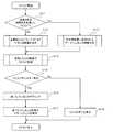
次に、実施形態の一例としてのストレージ装置1における、LUNの重要度に基づくリビルド処理順序の決定方法(第1の優先順位設定方法)を、図11に示すフローチャート(ステップS21〜S26)に従って説明する。In step S17, information notifying the LUN for which the rebuild process has been completed is displayed on the display of the management terminal (not shown) together with the fact that an error has occurred during the rebuild process, and the process ends. In addition, you may display such information (notification) on displays, such as the
Next, a rebuild processing order determination method (first priority setting method) based on LUN importance in the
ステップS21において、情報取得部171が、LUN管理テーブル61を参照して、故障RAIDグループ30aにおけるLUNを確認し、故障RAIDグループ30a上に形成されているLUNをリストアップする。
以下、故障RAIDグループ30aにL1〜L6の6つのLUNが形成されている例について示す。In step S21, the
Hereinafter, an example in which six LUNs L1 to L6 are formed in the
ステップS22において、情報取得部171は、セッション情報を参照して、リストアップされた各LUNについて、OPCのコピー元LUNもしくはコピー先LUNとなっているか否かをそれぞれ確認する。そして、情報取得部171は、各LUNを、“OPC元”,“OPC先”及び“その他”の3つのグループに分類する。
図11に示す例においては、L1,L2およびL3が“OPC元”であり、L6が“OPC先”であり、L4及びL5が“その他”である。In step S22, the
In the example shown in FIG. 11, L1, L2, and L3 are “OPC sources”, L6 is “OPC destination”, and L4 and L5 are “others”.
ステップS23において、情報取得部171は、OPC元となっているLUNについて、セッション情報を参照することで、そのコピー先LUN(OPC先LUN)を確認する。
図11に示す例においては、OPC元であるL1のOPC先がL1′であり、OPC元であるL2のOPC先がL2′、OPC元であるL3のOPC先がL3′である。In step S23, the
In the example shown in FIG. 11, the OPC destination of the LPC that is the OPC source is L1 ′, the OPC destination of the L2 that is the OPC source is L2 ′, and the OPC destination of the L3 that is the OPC source is L3 ′.
ステップS24において、情報取得部171は、アクセス履歴DB66を参照して、ステップS23において確認したOPC先のL1′,L2′及びL3′のそれぞれについてのシーケンシャルリード回数を取得する。
LUN選択部17の第1決定部172は、取得されたシーケンシャルリード回数に応じてその値が多いものから順にOPC先のL1′,L2′及びL3′を順位付けし、更に、その設定された順位に応じてOPC元のL1,L2及びL3の優先順位を設定する(順序付ける)。In step S24, the
The
例えば、OPC先のL1′,L2′及びL3′において、シーケンシャルリード回数が、L2′,L1′,L3′の順で多い場合には、これに従ってOPC元の優先順位はL2,L1,L3の順となる。
次に、ステップS25において、第1決定部172は、ステップS22において“その他”に分類したLUN、すなわち、“OPC元”及び“OPC先”以外のLUNに対して優先順位を設定する。For example, when the number of sequential reads in the OPC destinations L1 ′, L2 ′ and L3 ′ is large in the order of L2 ′, L1 ′ and L3 ′, the priority of the OPC source is L2, L1 and L3 accordingly. In order.
Next, in step S25, the first determining
具体的には、第1決定部172は、メモリ106のアクセス履歴情報65c,65bを参照して、これらの各LUNについて、アクセス回数が多いLUNから順番にリビルド処理の優先順位を設定する。
例えば、“その他”に分類されたL4及びL5について、L5に対するアクセス回数がL4よりも多い場合には、これらのLUNの優先順位はL5,L4の順となる。Specifically, the
For example, for L4 and L5 classified as “others”, when the number of accesses to L5 is greater than L4, the priorities of these LUNs are in the order of L5 and L4.
その後、ステップS26において、第1決定部172は、ステップS24〜S25においてそれぞれ設定した優先順位に基づき、故障RAIDグループ30aにL1〜L6の6つのLUNのリビルド処理順序を設定する。
すなわち、ステップS24において設定したOPC元の各LUN、ステップS25において設定したその他の各LUN、OPC先のLUNの順にリビルド処理順序が設定される。Thereafter, in step S26, the
That is, the rebuild process order is set in the order of each LUN of the OPC source set in step S24, each other LUN set in step S25, and the LUN of the OPC destination.
なお、ステップS22において“その他”に分類されたLUNが複数ある場合には、これらのLUNに対して、任意の優先順位を設定してもよく、また、アクセス履歴DB66を参照して、アクセス回数が多いものが順に優先順位を設定してもよく、種々変形して実施することができる。
図11に示す例においては、L1〜L6に対して、L2,L1,L3,L5,L4,L6の順にリビルド処理順序が設定される。When there are a plurality of LUNs classified as “others” in step S22, an arbitrary priority order may be set for these LUNs, and the access count is referred to the
In the example shown in FIG. 11, the rebuild process order is set in the order of L2, L1, L3, L5, L4, and L6 for L1 to L6.
次に、実施形態の一例としてのストレージ装置1における、本ストレージ装置1が使用される時間帯を考慮したリビルド処理順序の決定方法(第2の優先順位設定方法)を、図12に示すフローチャート(ステップS31〜S33)に従って説明する。
ステップS31において、情報取得部171が、LUN管理テーブル61を参照して、故障RAIDグループ30aにおけるLUNを確認し、故障RAIDグループ30a上に形成されているLUNをリストアップする。Next, in the
In step S31, the
以下、故障RAIDグループ30aにL1〜L6の6つのLUNが形成されている例について示す。
ステップS32において、情報取得部171は、ディスク情報67を参照して、故障RAIDグループ30aに含まれる故障ディスク31aの性能情報を取得する。また、情報取得部171は、収集した記憶装置31の性能情報に基づいてリビルド時間情報68を参照して、その記憶装置31の性能情報に相当するリビルド時間を取得する。Hereinafter, an example in which six LUNs L1 to L6 are formed in the
In step S32, the
そして、第2決定部173は、情報取得部171が故障ディスク31aの性能情報に基づいてリビルド時間情報68から取得したリビルド時間を、予測リビルド時間として見積もる。
図12に示す例においては、故障ディスク30aが「データ容量900GB、モータの回転速度が10KrpmのSASディスク」であり、そのリビルド時間が5時間であったものとする。この場合、予測リビルド時間は5時間となる。Then, the
In the example shown in FIG. 12, it is assumed that the failed
ステップS33において、第2決定部173は、リビルド開始予定時刻と予測リビルド時間とに基づいて、予測リビルド時間帯を決定する。そして、第2決定部173は、アクセス履歴DB66に基づいて、この決定した予測リビルド時間帯での各LUNのアクセス実績に応じて各LUNへのリビルド処理の優先順位を設定する。
すなわち、第2決定部173は、各LUNについて、予測リビルド時間帯におけるアクセス回数小計の合計(過去のアクセス実績の統計情報)を算出し、予測リビルド時間帯におけるアクセス回数の合計値が多い順でリビルド処理を行なうよう、各LUNへの順番付を行なう。In step S33, the
That is, the
図12に示す例においては、リビルド処理順序は、L1,L6,L5,L2,L4,L3の順となる。
次に、実施形態の一例としてのストレージ装置1におけるリビルド処理部13によるリビルド処理を、図13に示すフローチャート(ステップC1〜C9)に従って説明する。
ステップC1において、リビルド処理部13は、LUN選択部17によって設定されたリビルド処理順序を取得する。また、リビルド処理部13は、LUN管理テーブル61を参照することでLUN数を取得する。LUN管理テーブル61はLUN毎に作成されるので、例えばLUN管理テーブル61の数を参照することで、RAIDグループ30aに形成されているLUNの数を把握することができる。又、リビルド処理部13は、処理中のLUNを示す図示しない処理中ポインタに、リビルド処理順序における先頭のLUN(LUN域)を示す情報を記憶する。この処理中ポインタを参照することで、リビルド処理の進捗状況を把握することができる。In the example shown in FIG. 12, the rebuild process order is L1, L6, L5, L2, L4, L3.
Next, rebuild processing by the
In step C <b> 1, the
ステップC2において、リビルド処理部13は、処理中ポインタを参照して、未処理のLUN数を確認する。
未処理のLUN数が1つ以上ある場合には(ステップC2のNOルート参照)、ステップC3において、処理中LUNの情報に基づき、生き残っている各リビルド元ディスク31aを調べ、この生き残っているリビルド元ディスク31aから、RAIDストライプ分のデータを読み出し、メモリ106の所定の領域に格納する。In step C2, the
When the number of unprocessed LUNs is one or more (see NO route in step C2), in step C3, each remaining rebuild
ステップC4において、リビルド処理部13は、各リビルド元ディスク31aから読み出したデータを用いて故障ディスク31aの復元を行なう(復元データ作成)。
ステップC5において、リビルド処理部13は、故障ディスク31に対してアサインされた予備ディスク31bの所定位置(元と同じ位置)へ復元データを書き出す。
ステップC6において、リビルド処理部13は、LUN管理テーブル61の項8のリビルド済サイズに、リビルドが完了したデータサイズ(リビルド済サイズ)を加算(up)する。In step C4, the
In step C5, the
In step C <b> 6, the
ステップC7において、リビルド処理部13は、処理中のLUNのリビルド処理が完了したか否かを確認する。この確認の結果(ステップC8)、リビルド処理が完了していない場合には(ステップC8のNOルート参照)、ステップC3に戻る。
一方、リビルド処理が完了した場合には(ステップC8のYESルート参照)、ステップC9に移行する。In step C7, the
On the other hand, when the rebuild process is completed (see YES route in step C8), the process proceeds to step C9.
ステップC9において、リビルド処理部13は、LUN管理テーブル61の項5のLUNの状態に“リビルド済”を設定する。又、リビルド処理部13は、未処理のLUN数をデクリメントするとともに、リビルド処理順序における次のLUNを処理中ポインタに記憶する。その後、ステップC2に戻る。
ステップC2において、未処理のLUN数が0である場合には(ステップC2のYESルート参照)、処理を終了する。In step C <b> 9, the
In step C2, if the number of unprocessed LUNs is 0 (see YES route in step C2), the process is terminated.
このように、実施形態の一例としてのストレージ装置1によれば、LUN選択部17が、故障RAIDグループ30aに形成されていたLUNに対して、リビルド処理により復元させる順序(リビルド処理順序)を設定する。そして、リビルド処理部13は、故障RAIDグループ30aに備えられていた複数のLUNを、LUN選択部17によって設定されたリビルド処理順序に従って順番に再構築する。 As described above, according to the
これにより、高い優先順位を設定したLUNを早期に再構築することができ、利便性が高い。また、リビルド処理の途中リビルド元ディスク31aに何らかの障害が発生し、リビルド処理を最後まで実行することができない場合でも、高い優先順位を設定したLUNについては、再構築できる可能性が高く、信頼性も向上する。
また、LUN選択部17において、第1決定部172がLUNの重要度に基づきリビルド処理順序を決定する。これにより、重要度が高いLUNを早期に再構築することができる。As a result, LUNs set with high priority can be reconstructed at an early stage, which is highly convenient. Even if some failure occurs in the
In the
例えば、第1決定部172が、所謂D2D2Tのバックアップ構成がされているコピー元LUNをリビルド処理の優先順位が高いものとして設定することで、ユーザにとって重要なデータを含むLUNを早期に再構築することができる。
また、複数のLUN間において、アクセス履歴においてアクセス回数が多いLUNをリビルド処理の優先順位が高いものとして設定することでも、ユーザにとって重要なデータを含むLUNを早期に再構築することができる。For example, the first determining
In addition, it is possible to reconstruct a LUN including data important to the user at an early stage by setting a LUN having a high number of accesses in the access history as having a high rebuild processing priority among a plurality of LUNs.
さらに、第2決定部173が、本ストレージ装置1が使用される時間帯を考慮したリビルド処理順序を決定する。すなわち、第2決定部173が、リビルド先ディスク(復元先記憶装置)31bへのリビルド処理に要する時間を見積もり、予測リビルド時間帯を設定する。そして、第2決定部173は、アクセス履歴DB66を参照して、予測リビルド時間帯と同時間帯でのアクセス実績に応じて各LUNへのリビルド処理の優先順位を設定する。 Furthermore, the
これにより、予測リビルド時間帯においてアクセス数が高くなると予想されるLUNをリビルド処理の優先順位が高いものとして設定することでも、ユーザにとって重要なデータを含むLUNを早期に再構築することができる。
そして、開示の技術は上述した実施形態に限定されるものではなく、本実施形態の趣旨を逸脱しない範囲で種々変形して実施することができる。本実施形態の各構成及び各処理は、必要に応じて取捨選択することができ、あるいは適宜組み合わせてもよい。As a result, the LUN including data important for the user can be reconstructed at an early stage even by setting the LUN that is expected to have a high access number in the predicted rebuilding time period as having a high priority for the rebuild process.
The disclosed technology is not limited to the above-described embodiment, and various modifications can be made without departing from the spirit of the present embodiment. Each structure and each process of this embodiment can be selected as needed, or may be combined suitably.
例えば、上述した実施形態においては、RAIDグループ30aが4本(3本+1本)のRAID構成ディスク31aによりRAID5を実現している例を示しているが、これに限定されるものではない。例えば、RAID2〜4やRAID50(5+0)、RAID6,RAID10等、種々変形して実施することができる。
また、上述した実施形態においては、リビルド時間情報68として、記憶装置31の性能情報に対してリビルド時間を対応付け、第2決定部173が、リビルド先の記憶装置31bの性能情報に基づき、このリビルド時間情報68を参照することでリビルド時間を取得しているが、これに限定されるものではなく種々変形して実施することができる。For example, in the above-described embodiment, an example is shown in which
Further, in the above-described embodiment, the rebuild time is associated with the performance information of the storage device 31 as the
例えば、リビルド時間情報68として、記憶装置31毎にリビルド時間を対応付けたものを用いてもよい。また、記憶装置31の性能(容量,回転速度,RAID種別等)を数値化し、これらの数値を用いて演算を行なうことでリビルド時間を求めてもよい。この場合、数値化した記憶装置31の性能情報や演算式がリビルド時間情報68として機能する。 For example, as the
また、上述した実施形態において、第1決定部172は、OPCのコピー元となっているLUNであって、そのコピー先LUNにシーケンシャルリードアクセスが発生しているもののリビルド処理の優先順位を最も高く設定しているが、これに限定されるものではない。例えば、OPCのコピー元となっているLUNであって、そのコピー先LUNにシーケンシャル以外のリードアクセスが多く発生しているもののリビルド処理の優先順位を最も高く設定してもよい。 In the above-described embodiment, the
さらに、上述した実施形態においては、メモリ106にアクセス履歴情報65c及びアクセス履歴情報65bの2世代分のアクセス履歴情報65を格納しているが、これに限定されるものではなく種々変形して実施することができる。
例えば、メモリ106に1世代分の、すなわちカレントのアクセス履歴情報65cだけを格納してもよく、また、カレントのアクセス履歴情報65cを含む3世代分以上のアクセス履歴情報65を格納してもよい。第1決定部172は、メモリ106に格納されているアクセス履歴情報65に基づいてリビルド処理の優先順位を設定する。Furthermore, in the embodiment described above, the
For example, only one generation of current
性能情報は、データ容量,回転速度,RAID構成に限定されるものではない。例えば、記憶装置31に備えられたインタフェースの種類やデータ転送速度等であってもよい
また、上述した開示により本実施形態を当業者によって実施・製造することが可能である。
以上の実施形態に関し、更に以下の付記を開示する。The performance information is not limited to data capacity, rotation speed, and RAID configuration. For example, it may be the type of interface provided in the storage device 31, the data transfer speed, or the like. The embodiment can be implemented and manufactured by those skilled in the art based on the above-described disclosure.
Regarding the above embodiment, the following additional notes are disclosed.
(付記1)
冗長構成がなされた複数の記憶装置および予備記憶装置と通信路を介して通信可能に接続されるストレージ制御装置であって、
前記複数の記憶装置を用いて構成される複数の論理ボリュームに対するアクセス履歴情報を取得するアクセス履歴取得部と、
前記アクセス履歴取得部によって取得された前記アクセス履歴情報に基づき、前記複数の論理ボリュームのうち、優先して復元処理を行なう優先論理ボリュームを決定する論理ボリューム決定部と、
復元対象記憶装置における前記優先論理ボリュームを、前記複数の記憶装置のうちの前記復元対象記憶装置以外の記憶装置から読み出した復元用データを用いて、復元先記憶装置に復元する復元部と
を備えることを特徴とする、ストレージ制御装置。(Appendix 1)
A storage control device that is communicably connected via a communication path to a plurality of redundant storage devices and spare storage devices,
An access history acquisition unit that acquires access history information for a plurality of logical volumes configured using the plurality of storage devices;
Based on the access history information acquired by the access history acquisition unit, among the plurality of logical volumes, a logical volume determination unit that determines a priority logical volume to be preferentially restored,
A restoration unit that restores the priority logical volume in the restoration target storage device to the restoration destination storage device using restoration data read from a storage device other than the restoration target storage device among the plurality of storage devices; A storage control device.
(付記2)
前記論理ボリューム決定部が、
前記アクセス履歴情報に基づき、重要度が高いと判断される前記論理ボリュームを前記優先論理ボリュームとして決定することを特徴とする、付記1記載のストレージ制御装置。(Appendix 2)
The logical volume determination unit
The storage control apparatus according to
(付記3)
前記論理ボリューム決定部が、
バックアップコピーがされている論理ボリュームであって、そのバックアップ先にリードが発生している論理ボリュームを、前記優先論理ボリュームとして決定することを特徴とする、付記2記載のストレージ制御装置。(Appendix 3)
The logical volume determination unit
The storage control apparatus according to
(付記4)
前記リードがシーケンシャルリードであることを特徴とする、付記3記載のストレージ制御装置。
(付記5)
前記論理ボリューム決定部が、
前記復元対象記憶装置における異常検知時よりも前の所定時間帯に行なわれたアクセス回数が多い論理ボリュームを、前記優先論理ボリュームとして決定することを特徴とする、付記2〜4のいずれか1項に記載のストレージ制御装置。(Appendix 4)
The storage control apparatus according to
(Appendix 5)
The logical volume determination unit
Any one of
(付記6)
前記復元部による前記復元対象記憶装置の復元が行なわれる時間帯を予測する復元時間帯予測部をそなえ、
前記論理ボリューム決定部が、
前記アクセス履歴情報と予測された前記復元が行なわれる時間帯とに基づき、当該時間帯と同時間帯での、前記アクセス履歴情報においてアクセス頻度が高い論理ボリュームを、前記優先論理ボリュームとして決定することを特徴とする、付記2記載のストレージ制御装置。(Appendix 6)
A restoration time zone prediction unit for predicting a time zone in which the restoration target storage device is restored by the restoration unit;
The logical volume determination unit
Based on the access history information and the predicted time zone in which the restoration is performed, a logical volume having a high access frequency in the access history information in the same time zone as the time zone is determined as the priority logical volume. The storage control device according to
(付記7)
前記復元時間帯予測部が、前記記憶装置に関してデータ復元の所要時間を示す復元時間情報に基づき、前記復元対象記憶装置の復元に要する時間を予測することを特徴とする、付記6記載のストレージ制御装置。
(付記8)
冗長構成がなされた複数の記憶装置を備えるとともに、複数の論理ボリュームを備えるストレージシステムにおいて、
各論理ボリュームに対するアクセス履歴情報を取得するアクセス履歴取得部と、
前記アクセス履歴取得部によって取得された前記アクセス履歴情報に基づき、前記複数の論理ボリュームのうち、優先して復元処理を行なう優先論理ボリュームを決定する論理ボリューム決定部と、
復元対象記憶装置における前記優先論理ボリュームを、前記複数の記憶装置のうちの前記復元対象記憶装置以外の記憶装置から読み出した復元用データを用いて、復元先記憶装置に復元する復元部と
を備えることを特徴とする、ストレージシステム。(Appendix 7)
The storage control according to claim 6, wherein the restoration time zone prediction unit predicts a time required for restoration of the restoration target storage device based on restoration time information indicating a time required for data restoration with respect to the storage device. apparatus.
(Appendix 8)
In a storage system including a plurality of storage devices configured in a redundant configuration and a plurality of logical volumes,
An access history acquisition unit for acquiring access history information for each logical volume;
Based on the access history information acquired by the access history acquisition unit, among the plurality of logical volumes, a logical volume determination unit that determines a priority logical volume to be preferentially restored,
A restoration unit that restores the priority logical volume in the restoration target storage device to the restoration destination storage device using restoration data read from a storage device other than the restoration target storage device among the plurality of storage devices; A storage system characterized by that.
(付記9)
前記論理ボリューム決定部が、
前記アクセス履歴情報に基づき、重要度が高いと判断される前記論理ボリュームを前記優先論理ボリュームとして決定することを特徴とする、付記8記載のストレージシステム。(Appendix 9)
The logical volume determination unit
The storage system according to
(付記10)
前記論理ボリューム決定部が、
バックアップコピーがされている論理ボリュームであって、そのバックアップ先にリードが発生している論理ボリュームを、前記優先論理ボリュームとして決定することを特徴とする、付記9記載のストレージシステム。(Appendix 10)
The logical volume determination unit
The storage system according to
(付記11)
前記リードがシーケンシャルリードであることを特徴とする、付記10記載のストレージシステム。
(付記12)
前記論理ボリューム決定部が、
前記復元対象記憶装置における異常検知時よりも前の所定時間帯に行なわれたアクセス回数が多い論理ボリュームを、前記優先論理ボリュームとして決定することを特徴とする、付記9〜11のいずれか1項に記載のストレージシステム。(Appendix 11)
The storage system according to
(Appendix 12)
The logical volume determination unit
Any one of
(付記13)
前記復元部による前記復元対象記憶装置の復元が行なわれる時間帯を予測する復元時間帯予測部をそなえ、
前記論理ボリューム決定部が、
前記アクセス履歴情報と予測された前記復元が行なわれる時間帯とに基づき、当該時間帯と同時間帯での、前記アクセス履歴情報においてアクセス頻度が高い論理ボリュームを、前記優先論理ボリュームとして決定することを特徴とする、付記9記載のストレージシステム。(Appendix 13)
A restoration time zone prediction unit for predicting a time zone in which the restoration target storage device is restored by the restoration unit;
The logical volume determination unit
Based on the access history information and the predicted time zone in which the restoration is performed, a logical volume having a high access frequency in the access history information in the same time zone as the time zone is determined as the priority logical volume. The storage system according to
(付記14)
前記復元時間帯予測部が、前記記憶装置に関してデータ復元の所要時間を示す復元時間情報に基づき、前記復元対象記憶装置の復元に要する時間を予測することを特徴とする、付記13記載のストレージシステム。
(付記15)
冗長構成がなされた複数の記憶装置および予備記憶装置と通信路を介して通信可能に接続されるコンピュータに、
前記複数の記憶装置を用いて構成される複数の論理ボリュームに対するアクセス履歴情報を取得し、
取得された前記アクセス履歴情報に基づき、前記複数の論理ボリュームのうち、優先して復元処理を行なう優先論理ボリュームを決定し、
復元対象記憶装置における前記優先論理ボリュームを、前記複数の記憶装置のうちの前記復元対象記憶装置以外の記憶装置から読み出した復元用データを用いて、復元先記憶装置に復元する
処理を実行させる、ストレージ制御プログラム。(Appendix 14)
14. The storage system according to
(Appendix 15)
To a computer connected to be able to communicate with a plurality of storage devices and spare storage devices configured in a redundant manner via a communication path,
Obtaining access history information for a plurality of logical volumes configured using the plurality of storage devices;
Based on the acquired access history information, a priority logical volume to be preferentially restored among the plurality of logical volumes is determined,
Executing the process of restoring the priority logical volume in the restoration target storage device to the restoration destination storage device using the restoration data read from the storage device other than the restoration target storage device among the plurality of storage devices; Storage control program.
(付記16)
前記アクセス履歴情報に基づき、重要度が高いと判断される前記論理ボリュームを前記優先論理ボリュームとして決定する
処理を前記コンピュータに実行させる、付記15記載のストレージ制御プログラム。
(付記17)
バックアップコピーがされている論理ボリュームであって、そのバックアップ先にリードが発生している論理ボリュームを、前記優先論理ボリュームとして決定する
処理を前記コンピュータに実行させる、付記16記載のストレージ制御プログラム。(Appendix 16)
The storage control program according to supplementary note 15, which causes the computer to execute a process of determining, as the priority logical volume, the logical volume that is determined to be highly important based on the access history information.
(Appendix 17)
18. The storage control program according to appendix 16, wherein the computer executes a process of determining a logical volume that has been backed up and that has been read to the backup destination as the priority logical volume.
(付記18)
前記復元対象記憶装置における異常検知時よりも前の所定時間帯に行なわれたアクセス回数が多い論理ボリュームを、前記優先論理ボリュームとして決定する
処理を前記コンピュータに実行させる、付記16又は付記17記載のストレージ制御プログラム。(Appendix 18)
The supplementary note 16 or the
(付記19)
前記復元対象記憶装置の復元が行なわれる時間帯を予測し、
前記アクセス履歴情報と予測された前記復元が行なわれる時間帯とに基づき、当該時間帯と同時間帯での、前記アクセス履歴情報においてアクセス頻度が高い論理ボリュームを、前記優先論理ボリュームとして決定する
処理を前記コンピュータに実行させる、付記16記載のストレージ制御プログラム。(Appendix 19)
Predicting a time zone when the restoration target storage device is restored,
A process of determining, as the priority logical volume, a logical volume having a high access frequency in the access history information in the same time zone as the time zone based on the access history information and the predicted time zone in which the restoration is performed. The storage control program according to appendix 16, wherein the computer is executed.
(付記20)
前記記憶装置に関してデータ復元の所要時間を示す復元時間情報に基づき、前記復元対象記憶装置の復元に要する時間を予測する
処理を前記コンピュータに実行させる、付記19記載のストレージ制御プログラム。(Appendix 20)
The storage control program according to
1 ストレージ装置
2,2a,2b ホスト装置
3,3a,3b スイッチ
11 IO制御部
12 RAID制御部
13 リビルド処理部(復元部)
17 LUN選択部
18 アクセス履歴作成部
19 コピー処理部
30 ドライブエンクロージャ
30a RAIDグループ
30b 予備ディスクグループ
31 記憶装置
31a,31a−1〜31a−4 リビルド元ディスク,記憶装置
31b,31b−1〜31b−4 リビルド先ディスク,記憶装置
40 コントローラエンクロージャ
61 LUN管理テーブル
62 仮/実ボリューム変換テーブル
63 ディスク構成情報
64 RAID構成テーブル
65,65b,65c アクセス履歴情報
66 アクセス履歴データベース(アクセス履歴情報)
67 ディスク情報
68 リビルド時間情報(復元時間情報)
100 コントローラ(ストレージ制御装置)
101,101a,101b ポート
103 デバイスアダプタ
106 メモリ
107 フラッシュメモリ
108 IOC
110 CPU
171 情報取得部(アクセス履歴取得部)
172 第1決定部(論理ボリューム決定部)
173 第2決定部(復元時間帯予測部,論理ボリューム決定部)1
17
67
100 controller (storage controller)
101, 101a, 101b
110 CPU
171 Information acquisition unit (access history acquisition unit)
172 First determination unit (logical volume determination unit)
173 Second determination unit (restoration time zone prediction unit, logical volume determination unit)
Claims (9)
Translated fromJapanese前記複数の記憶装置を用いて構成される複数の論理ボリュームに対するアクセス履歴情報を取得するアクセス履歴取得部と、
前記アクセス履歴取得部によって取得された前記アクセス履歴情報に基づき、前記複数の論理ボリュームのうち、優先して復元処理を行なう優先論理ボリュームを決定する論理ボリューム決定部と、
復元対象記憶装置における前記優先論理ボリュームを、前記複数の記憶装置のうちの前記復元対象記憶装置以外の記憶装置から読み出した復元用データを用いて、復元先記憶装置に復元する復元部と
を備えることを特徴とする、ストレージ制御装置。A storage control device that is communicably connected via a communication path to a plurality of redundant storage devices and spare storage devices,
An access history acquisition unit that acquires access history information for a plurality of logical volumes configured using the plurality of storage devices;
Based on the access history information acquired by the access history acquisition unit, among the plurality of logical volumes, a logical volume determination unit that determines a priority logical volume to be preferentially restored,
A restoration unit that restores the priority logical volume in the restoration target storage device to the restoration destination storage device using restoration data read from a storage device other than the restoration target storage device among the plurality of storage devices; A storage control device.
前記アクセス履歴情報に基づき、重要度が高いと判断される前記論理ボリュームを前記優先論理ボリュームとして決定することを特徴とする、請求項1記載のストレージ制御装置。The logical volume determination unit
The storage control apparatus according to claim 1, wherein the logical volume that is determined to be highly important is determined as the priority logical volume based on the access history information.
バックアップコピーがされている論理ボリュームであって、そのバックアップ先にリードが発生している論理ボリュームを、前記優先論理ボリュームとして決定することを特徴とする、請求項2記載のストレージ制御装置。The logical volume determination unit
3. The storage control apparatus according to claim 2, wherein a logical volume in which a backup copy is made and a read is generated at the backup destination is determined as the priority logical volume.
前記復元対象記憶装置における異常検知時よりも前の所定時間帯に行なわれたアクセス回数が多い論理ボリュームを、前記優先論理ボリュームとして決定することを特徴とする、請求項2〜4のいずれか1項に記載のストレージ制御装置。The logical volume determination unit
5. The logical volume having a large number of accesses performed in a predetermined time zone before the time of detecting an abnormality in the restoration target storage device is determined as the priority logical volume. The storage control device according to item.
前記論理ボリューム決定部が、
前記アクセス履歴情報と予測された前記復元が行なわれる時間帯とに基づき、当該時間帯と同時間帯での、前記アクセス履歴情報においてアクセス頻度が高い論理ボリュームを、前記優先論理ボリュームとして決定することを特徴とする、請求項2記載のストレージ制御装置。A restoration time zone prediction unit for predicting a time zone in which the restoration target storage device is restored by the restoration unit;
The logical volume determination unit
Based on the access history information and the predicted time zone in which the restoration is performed, a logical volume having a high access frequency in the access history information in the same time zone as the time zone is determined as the priority logical volume. The storage control device according to claim 2, wherein:
各論理ボリュームに対するアクセス履歴情報を取得するアクセス履歴取得部と、
前記アクセス履歴取得部によって取得された前記アクセス履歴情報に基づき、前記複数の論理ボリュームのうち、優先して復元処理を行なう優先論理ボリュームを決定する論理ボリューム決定部と、
復元対象記憶装置における前記優先論理ボリュームを、前記複数の記憶装置のうちの前記復元対象記憶装置以外の記憶装置から読み出した復元用データを用いて、復元先記憶装置に復元する復元部と
を備えることを特徴とする、ストレージシステム。In a storage system including a plurality of storage devices configured in a redundant configuration and a plurality of logical volumes,
An access history acquisition unit for acquiring access history information for each logical volume;
Based on the access history information acquired by the access history acquisition unit, among the plurality of logical volumes, a logical volume determination unit that determines a priority logical volume to be preferentially restored,
A restoration unit that restores the priority logical volume in the restoration target storage device to the restoration destination storage device using restoration data read from a storage device other than the restoration target storage device among the plurality of storage devices; A storage system characterized by that.
前記複数の記憶装置を用いて構成される複数の論理ボリュームに対するアクセス履歴情報を取得し、
取得された前記アクセス履歴情報に基づき、前記複数の論理ボリュームのうち、優先して復元処理を行なう優先論理ボリュームを決定し、
復元対象記憶装置における前記優先論理ボリュームを、前記複数の記憶装置のうちの前記復元対象記憶装置以外の記憶装置から読み出した復元用データを用いて、復元先記憶装置に復元する
処理を実行させる、ストレージ制御プログラム。To a computer connected to be able to communicate with a plurality of storage devices and spare storage devices configured in a redundant manner via a communication path,
Obtaining access history information for a plurality of logical volumes configured using the plurality of storage devices;
Based on the acquired access history information, a priority logical volume to be preferentially restored among the plurality of logical volumes is determined,
Executing the process of restoring the priority logical volume in the restoration target storage device to the restoration destination storage device using the restoration data read from the storage device other than the restoration target storage device among the plurality of storage devices; Storage control program.
Priority Applications (2)
| Application Number | Priority Date | Filing Date | Title |
|---|---|---|---|
| JP2014182866AJP2016057795A (en) | 2014-09-09 | 2014-09-09 | Storage control device, storage system, and storage control program |
| US14/809,720US20160070490A1 (en) | 2014-09-09 | 2015-07-27 | Storage control device and storage system |
Applications Claiming Priority (1)
| Application Number | Priority Date | Filing Date | Title |
|---|---|---|---|
| JP2014182866AJP2016057795A (en) | 2014-09-09 | 2014-09-09 | Storage control device, storage system, and storage control program |
Publications (1)
| Publication Number | Publication Date |
|---|---|
| JP2016057795Atrue JP2016057795A (en) | 2016-04-21 |
Family
ID=55437562
Family Applications (1)
| Application Number | Title | Priority Date | Filing Date |
|---|---|---|---|
| JP2014182866AWithdrawnJP2016057795A (en) | 2014-09-09 | 2014-09-09 | Storage control device, storage system, and storage control program |
Country Status (2)
| Country | Link |
|---|---|
| US (1) | US20160070490A1 (en) |
| JP (1) | JP2016057795A (en) |
Cited By (3)
| Publication number | Priority date | Publication date | Assignee | Title |
|---|---|---|---|---|
| JP2019160124A (en)* | 2018-03-16 | 2019-09-19 | 富士通株式会社 | Storage management device, storage system, and storage management program |
| JP2021105871A (en)* | 2019-12-26 | 2021-07-26 | 株式会社日立製作所 | Storage system |
| JP2021182268A (en)* | 2020-05-19 | 2021-11-25 | Necプラットフォームズ株式会社 | Controller, information processing device, information processing method, and program |
Families Citing this family (18)
| Publication number | Priority date | Publication date | Assignee | Title |
|---|---|---|---|---|
| US8819208B2 (en) | 2010-03-05 | 2014-08-26 | Solidfire, Inc. | Data deletion in a distributed data storage system |
| US9838269B2 (en) | 2011-12-27 | 2017-12-05 | Netapp, Inc. | Proportional quality of service based on client usage and system metrics |
| US9054992B2 (en) | 2011-12-27 | 2015-06-09 | Solidfire, Inc. | Quality of service policy sets |
| US20150244795A1 (en) | 2014-02-21 | 2015-08-27 | Solidfire, Inc. | Data syncing in a distributed system |
| US10133511B2 (en) | 2014-09-12 | 2018-11-20 | Netapp, Inc | Optimized segment cleaning technique |
| US9836229B2 (en) | 2014-11-18 | 2017-12-05 | Netapp, Inc. | N-way merge technique for updating volume metadata in a storage I/O stack |
| US11188665B2 (en)* | 2015-02-27 | 2021-11-30 | Pure Storage, Inc. | Using internal sensors to detect adverse interference and take defensive actions |
| US10235059B2 (en)* | 2015-12-01 | 2019-03-19 | Netapp, Inc. | Technique for maintaining consistent I/O processing throughput in a storage system |
| US10929022B2 (en) | 2016-04-25 | 2021-02-23 | Netapp. Inc. | Space savings reporting for storage system supporting snapshot and clones |
| US10642763B2 (en) | 2016-09-20 | 2020-05-05 | Netapp, Inc. | Quality of service policy sets |
| CN108228076B (en) | 2016-12-14 | 2020-10-16 | 华为技术有限公司 | Methods and hosts for accessing disks |
| US10831382B2 (en)* | 2017-11-29 | 2020-11-10 | International Business Machines Corporation | Prevent disk hardware failure for cloud applications |
| GB2580467B (en)* | 2018-09-20 | 2024-12-04 | Idera Inc | Database access, monitoring, and control system and method for reacting to suspicious database activities |
| US11068357B2 (en)* | 2019-06-03 | 2021-07-20 | EMC IP Holding Company LLC | Uninterrupted restore operation using a time based approach |
| US11403195B2 (en)* | 2019-08-07 | 2022-08-02 | Micron Technology, Inc. | Application of dynamic trim strategy in a die-protection memory sub-system |
| US11138123B2 (en)* | 2019-10-01 | 2021-10-05 | EMC IP Holding Company LLC | Local cache size control in a storage array |
| US12282574B2 (en) | 2022-06-28 | 2025-04-22 | International Business Machines Corporation | Generational access to safeguarded copy source volumes |
| US12367306B2 (en) | 2022-06-28 | 2025-07-22 | International Business Machines Corporation | Fine granularity read access to generational safeguarded copy data |
Family Cites Families (7)
| Publication number | Priority date | Publication date | Assignee | Title |
|---|---|---|---|---|
| JP3951835B2 (en)* | 2002-07-03 | 2007-08-01 | 株式会社日立製作所 | Business management method and business processing system |
| US8006128B2 (en)* | 2008-07-31 | 2011-08-23 | Datadirect Networks, Inc. | Prioritized rebuilding of a storage device |
| JP5521716B2 (en)* | 2010-04-06 | 2014-06-18 | 富士通株式会社 | Storage control program, storage control method, and storage control apparatus |
| WO2012029095A1 (en)* | 2010-09-03 | 2012-03-08 | Hitachi, Ltd. | Storage apparatus and control method of storage apparatus |
| WO2013035243A1 (en)* | 2011-09-08 | 2013-03-14 | 日本電気株式会社 | Cloud service recovery time prediction system, method and program |
| US20140215147A1 (en)* | 2013-01-25 | 2014-07-31 | Hewlett-Packard Development Company, L.P. | Raid storage rebuild processing |
| GB2513377A (en)* | 2013-04-25 | 2014-10-29 | Ibm | Controlling data storage in an array of storage devices |
- 2014
- 2014-09-09JPJP2014182866Apatent/JP2016057795A/ennot_activeWithdrawn
- 2015
- 2015-07-27USUS14/809,720patent/US20160070490A1/ennot_activeAbandoned
Cited By (4)
| Publication number | Priority date | Publication date | Assignee | Title |
|---|---|---|---|---|
| JP2019160124A (en)* | 2018-03-16 | 2019-09-19 | 富士通株式会社 | Storage management device, storage system, and storage management program |
| JP2021105871A (en)* | 2019-12-26 | 2021-07-26 | 株式会社日立製作所 | Storage system |
| JP7405608B2 (en) | 2019-12-26 | 2023-12-26 | 株式会社日立製作所 | storage system |
| JP2021182268A (en)* | 2020-05-19 | 2021-11-25 | Necプラットフォームズ株式会社 | Controller, information processing device, information processing method, and program |
Also Published As
| Publication number | Publication date |
|---|---|
| US20160070490A1 (en) | 2016-03-10 |
Similar Documents
| Publication | Publication Date | Title |
|---|---|---|
| JP2016057795A (en) | Storage control device, storage system, and storage control program | |
| JP6233086B2 (en) | Storage control device, storage system, and control program | |
| US10346253B2 (en) | Threshold based incremental flashcopy backup of a raid protected array | |
| JP4267420B2 (en) | Storage apparatus and backup acquisition method | |
| JP5954081B2 (en) | Storage control device, storage control method, and storage control program | |
| US9600375B2 (en) | Synchronized flashcopy backup restore of a RAID protected array | |
| US9588856B2 (en) | Restoring redundancy in a storage group when a storage device in the storage group fails | |
| JP5158074B2 (en) | Storage management program, storage management method, storage management device, and storage system | |
| US10120769B2 (en) | Raid rebuild algorithm with low I/O impact | |
| JP6064608B2 (en) | Storage device, backup program, and backup method | |
| US20140075240A1 (en) | Storage apparatus, computer product, and storage control method | |
| JP6097845B2 (en) | Storage system that backs up data to non-volatile cache memory | |
| JP4845724B2 (en) | Storage system with backup function | |
| US20090265510A1 (en) | Systems and Methods for Distributing Hot Spare Disks In Storage Arrays | |
| JP2009048497A (en) | A storage system with a function to change the data storage method using a pair of logical volumes | |
| TW201131351A (en) | System and method for optimizing redundancy restoration in distributed data layout environments | |
| JP2005135408A (en) | Hierarchical storage system | |
| WO2014132373A1 (en) | Storage system and memory device fault recovery method | |
| WO2014098872A1 (en) | Raid storage processing | |
| US20060236149A1 (en) | System and method for rebuilding a storage disk | |
| US20180307427A1 (en) | Storage control apparatus and storage control method | |
| US20130117502A1 (en) | Method for managing system firmware in nas server | |
| WO2016084156A1 (en) | Storage system | |
| JP6171616B2 (en) | Storage control device and storage control program | |
| JP6957845B2 (en) | Storage control device and storage device |
Legal Events
| Date | Code | Title | Description |
|---|---|---|---|
| A621 | Written request for application examination | Free format text:JAPANESE INTERMEDIATE CODE: A621 Effective date:20170605 | |
| A761 | Written withdrawal of application | Free format text:JAPANESE INTERMEDIATE CODE: A761 Effective date:20170620 |