JP2016057166A - Lighting fixture and position measuring system - Google Patents
Lighting fixture and position measuring systemDownload PDFInfo
- Publication number
- JP2016057166A JP2016057166AJP2014183691AJP2014183691AJP2016057166AJP 2016057166 AJP2016057166 AJP 2016057166AJP 2014183691 AJP2014183691 AJP 2014183691AJP 2014183691 AJP2014183691 AJP 2014183691AJP 2016057166 AJP2016057166 AJP 2016057166A
- Authority
- JP
- Japan
- Prior art keywords
- beacon
- unit
- disaster
- transmits
- terminal device
- Prior art date
- Legal status (The legal status is an assumption and is not a legal conclusion. Google has not performed a legal analysis and makes no representation as to the accuracy of the status listed.)
- Granted
Links
Images


Classifications
- G—PHYSICS
- G01—MEASURING; TESTING
- G01S—RADIO DIRECTION-FINDING; RADIO NAVIGATION; DETERMINING DISTANCE OR VELOCITY BY USE OF RADIO WAVES; LOCATING OR PRESENCE-DETECTING BY USE OF THE REFLECTION OR RERADIATION OF RADIO WAVES; ANALOGOUS ARRANGEMENTS USING OTHER WAVES
- G01S1/00—Beacons or beacon systems transmitting signals having a characteristic or characteristics capable of being detected by non-directional receivers and defining directions, positions, or position lines fixed relatively to the beacon transmitters; Receivers co-operating therewith
- G01S1/02—Beacons or beacon systems transmitting signals having a characteristic or characteristics capable of being detected by non-directional receivers and defining directions, positions, or position lines fixed relatively to the beacon transmitters; Receivers co-operating therewith using radio waves
- G01S1/04—Details
- G01S1/042—Transmitters
- G—PHYSICS
- G01—MEASURING; TESTING
- G01S—RADIO DIRECTION-FINDING; RADIO NAVIGATION; DETERMINING DISTANCE OR VELOCITY BY USE OF RADIO WAVES; LOCATING OR PRESENCE-DETECTING BY USE OF THE REFLECTION OR RERADIATION OF RADIO WAVES; ANALOGOUS ARRANGEMENTS USING OTHER WAVES
- G01S1/00—Beacons or beacon systems transmitting signals having a characteristic or characteristics capable of being detected by non-directional receivers and defining directions, positions, or position lines fixed relatively to the beacon transmitters; Receivers co-operating therewith
- G01S1/70—Beacons or beacon systems transmitting signals having a characteristic or characteristics capable of being detected by non-directional receivers and defining directions, positions, or position lines fixed relatively to the beacon transmitters; Receivers co-operating therewith using electromagnetic waves other than radio waves
- G01S1/703—Details
- G01S1/7032—Transmitters
- G01S1/7034—Mounting or deployment thereof
- G—PHYSICS
- G01—MEASURING; TESTING
- G01S—RADIO DIRECTION-FINDING; RADIO NAVIGATION; DETERMINING DISTANCE OR VELOCITY BY USE OF RADIO WAVES; LOCATING OR PRESENCE-DETECTING BY USE OF THE REFLECTION OR RERADIATION OF RADIO WAVES; ANALOGOUS ARRANGEMENTS USING OTHER WAVES
- G01S5/00—Position-fixing by co-ordinating two or more direction or position line determinations; Position-fixing by co-ordinating two or more distance determinations
- G01S5/02—Position-fixing by co-ordinating two or more direction or position line determinations; Position-fixing by co-ordinating two or more distance determinations using radio waves
- G01S5/0257—Hybrid positioning
- G01S5/0263—Hybrid positioning by combining or switching between positions derived from two or more separate positioning systems
- G01S5/0264—Hybrid positioning by combining or switching between positions derived from two or more separate positioning systems at least one of the systems being a non-radio wave positioning system
- H—ELECTRICITY
- H04—ELECTRIC COMMUNICATION TECHNIQUE
- H04B—TRANSMISSION
- H04B10/00—Transmission systems employing electromagnetic waves other than radio-waves, e.g. infrared, visible or ultraviolet light, or employing corpuscular radiation, e.g. quantum communication
- H04B10/11—Arrangements specific to free-space transmission, i.e. transmission through air or vacuum
- H04B10/114—Indoor or close-range type systems
- H04B10/1141—One-way transmission
- H—ELECTRICITY
- H04—ELECTRIC COMMUNICATION TECHNIQUE
- H04B—TRANSMISSION
- H04B10/00—Transmission systems employing electromagnetic waves other than radio-waves, e.g. infrared, visible or ultraviolet light, or employing corpuscular radiation, e.g. quantum communication
- H04B10/11—Arrangements specific to free-space transmission, i.e. transmission through air or vacuum
- H04B10/114—Indoor or close-range type systems
- H04B10/116—Visible light communication
- H—ELECTRICITY
- H04—ELECTRIC COMMUNICATION TECHNIQUE
- H04W—WIRELESS COMMUNICATION NETWORKS
- H04W4/00—Services specially adapted for wireless communication networks; Facilities therefor
- H04W4/02—Services making use of location information
- G—PHYSICS
- G01—MEASURING; TESTING
- G01S—RADIO DIRECTION-FINDING; RADIO NAVIGATION; DETERMINING DISTANCE OR VELOCITY BY USE OF RADIO WAVES; LOCATING OR PRESENCE-DETECTING BY USE OF THE REFLECTION OR RERADIATION OF RADIO WAVES; ANALOGOUS ARRANGEMENTS USING OTHER WAVES
- G01S2201/00—Indexing scheme relating to beacons or beacon systems transmitting signals capable of being detected by non-directional receivers and defining directions, positions, or position lines fixed relatively to the beacon transmitters
- G01S2201/01—Indexing scheme relating to beacons or beacon systems transmitting signals capable of being detected by non-directional receivers and defining directions, positions, or position lines fixed relatively to the beacon transmitters adapted for specific applications or environments
Landscapes
- Engineering & Computer Science (AREA)
- Physics & Mathematics (AREA)
- Computer Networks & Wireless Communication (AREA)
- General Physics & Mathematics (AREA)
- Radar, Positioning & Navigation (AREA)
- Remote Sensing (AREA)
- Electromagnetism (AREA)
- Signal Processing (AREA)
- Circuit Arrangement For Electric Light Sources In General (AREA)
- Audible And Visible Signals (AREA)
- Alarm Systems (AREA)
Abstract
Description
Translated fromJapanese本発明は、照明器具、及び、それを備える位置測位システムに関する。 The present invention relates to a lighting fixture and a position positioning system including the same.
光又は電波に識別情報を含ませたビーコンを照明器具から送信することにより、ビーコンを受信した端末装置の位置を特定する位置測位システムが提案されている(例えば、特許文献1参照)。ここで、ビーコンとは、位置測位のための識別情報を含む信号である。 There has been proposed a positioning system that identifies the position of a terminal device that has received a beacon by transmitting a beacon including identification information in light or radio waves from a lighting fixture (see, for example, Patent Document 1). Here, the beacon is a signal including identification information for position measurement.
最近では、位置測位システムに用いられる近距離無線通信技術として、Bluetooth(登録商標) Low Energy(BLE)の検討が進められている。このBLEを位置測位用の電波ビーコンとして用いた場合には、低消費電力な近距離無線通信による正確な位置測位が実現され得る。なお、電波ビーコンとは、電波に識別情報を含ませたビーコンである。 Recently, Bluetooth (registered trademark) Low Energy (BLE) has been studied as a short-range wireless communication technology used in the position measurement system. When this BLE is used as a radio beacon for position positioning, accurate position positioning by short-range wireless communication with low power consumption can be realized. A radio beacon is a beacon in which identification information is included in a radio wave.
しかしながら、屋内で位置測位をしようとした場合、BLEによる電波ビーコン(2.4GHzの信号)はマルチパスなどの影響を受けるために、正確に位置を補足することが難しい。一方で、電波ビーコンの出力を絞った場合、天井(つまり、床から3m程度の高さの位置)に電波ビーコンの送信機を取り付けたケースなどでは、場所によっては電波ビーコンを受信できず、限られた範囲でしか位置測位ができないなどの状況が発生する。 However, when positioning is attempted indoors, a radio beacon (2.4 GHz signal) by BLE is affected by multipath and the like, and thus it is difficult to accurately capture the position. On the other hand, when the output of radio beacons is reduced, radio beacons cannot be received depending on the location in cases where radio beacon transmitters are attached to the ceiling (that is, a position about 3 m above the floor). There are situations where positioning is possible only within the specified range.
また、天井などに取り付けた案内サイン(または、看板)などに電波ビーコンの送信機を装着しておくことで大まかな位置情報の発信源として案内サインを活用でき得る。ところが、案内サインなどは、隣接して設置されるケースが多く、案内サインから発射される電波ビーコンが干渉し、その結果、端末装置で電波ビーコンを受信できないという状況が発生し得る。特に、BLEによる電波ビーコンでは、アドバタイズ信号として3つの帯域しか使用できないため、電波ビーコン同士で干渉が生じ易い。そのために、地下道の交差する場所や駅の改札付近などの限られた場所に電波ビーコンを送信する複数の案内サインを設置することが困難になるという問題がある。 Further, by installing a radio wave beacon transmitter on a guide sign (or signboard) attached to a ceiling or the like, the guide sign can be used as a source of rough position information. However, guidance signs and the like are often installed adjacent to each other, and radio wave beacons emitted from the guidance signs interfere with each other. As a result, a situation in which the radio wave beacon cannot be received by the terminal device may occur. In particular, a radio wave beacon using BLE can use only three bands as an advertisement signal, and thus interference between radio wave beacons is likely to occur. For this reason, there is a problem that it is difficult to install a plurality of guide signs for transmitting radio wave beacons in a limited place such as a place where an underground passage intersects or near a ticket gate of a station.
そこで、本発明は、位置測位システムに用いられる照明器具であって限られた場所に複数台設置することが可能な照明器具、及び、それを備える位置測位システムを提供することを目的とする。 Therefore, an object of the present invention is to provide a lighting fixture that can be installed in a limited place and is a lighting fixture used in a position positioning system, and a position positioning system including the same.
上記目的を達成するために、本発明の一形態における照明器具は、位置測位システムに用いられる照明器具であって、電力を供給する電力供給部と、前記電力供給部から供給される電力で点灯する照明部と、前記電力供給部から供給される電力で動作し、位置測位に用いられる信号であるビーコンを送信するビーコン送信部とを備え、前記ビーコンには、第1送信電力で送信される長距離用ビーコンと、前記第1送信電力よりも小さい第2送信電力で送信される短距離用ビーコンとが含まれ、前記ビーコン送信部は、少なくとも前記長距離用ビーコンを間欠的に送信する。 In order to achieve the above object, a lighting fixture according to an aspect of the present invention is a lighting fixture used in a position positioning system, and is lit with a power supply unit that supplies power and power supplied from the power supply unit. And a beacon transmission unit that operates with power supplied from the power supply unit and transmits a beacon that is a signal used for position measurement, and the beacon is transmitted with a first transmission power. A long distance beacon and a short distance beacon transmitted at a second transmission power smaller than the first transmission power are included, and the beacon transmission unit intermittently transmits at least the long distance beacon.
また、上記目的を達成するために、本発明の一形態における位置測位システムは、上記照明器具と、前記照明器具から送信されるビーコンを受信し、受信した前記ビーコンを用いて位置測位を行う端末装置とを備える。 Moreover, in order to achieve the said objective, the position positioning system in one form of this invention is a terminal which receives the said lighting fixture and the beacon transmitted from the said lighting fixture, and performs position positioning using the received said beacon. Device.
本発明によれば、位置測位システムに用いられる照明器具であって限られた場所に複数台設置することが可能な照明器具、及び、それを用いた位置測位システムが実現される。 ADVANTAGE OF THE INVENTION According to this invention, it is a lighting fixture used for a positioning system, and the lighting fixture which can be installed two or more in the limited place and a position positioning system using the same are implement | achieved.
以下、本発明に係る照明器具及び位置測位システムの実施の形態について、図面を参照しながら具体的に説明する。 DESCRIPTION OF EMBODIMENTS Hereinafter, embodiments of a lighting apparatus and a positioning system according to the present invention will be specifically described with reference to the drawings.
なお、以下で説明する実施の形態は、いずれも本発明の一具体例を示すものである。以下の実施の形態で示される数値、構成要素、構成要素の配置位置及び接続形態、動作タイミングなどは、一例であり、本発明を限定する主旨ではない。また、以下の実施の形態における構成要素のうち、最上位概念を示す独立請求項に記載されていない構成要素については、任意の構成要素として説明する。 Note that each of the embodiments described below shows a specific example of the present invention. Numerical values, components, arrangement positions and connection forms of components, operation timings, and the like shown in the following embodiments are merely examples, and are not intended to limit the present invention. Further, among the constituent elements in the following embodiments, constituent elements that are not described in the independent claims indicating the highest concept will be described as optional constituent elements.
(実施の形態1)
まず、本発明の実施の形態1における位置測位システムについて説明する。(Embodiment 1)
First, the position positioning system in Embodiment 1 of this invention is demonstrated.
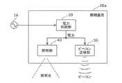
図1は、本発明の実施の形態1における位置測位システム10aの構成を示すブロック図である。位置測位システム10aは、端末装置14の位置測位を行うシステム(本実施の形態では、屋内位置測位システム)であり、複数の照明器具20a及び20bと、端末装置14とで構成される。なお、本実施の形態では、説明の便宜上、2台の照明器具20a及び20bが図示されているが、位置測位システム10aを構成する照明器具の台数は、1台であってもよいし、3台以上であってもよい。このことは、他の実施の形態でも同様である。 FIG. 1 is a block diagram showing a configuration of a
照明器具20a及び20bは、位置測位システムに用いられる照明器具であり、照明光を発するだけでなく、位置測位に用いられる信号(例えば、自器具に対応づけられた識別情報を含む信号)であるビーコンを送信する。本実施の形態では、照明器具20a及び20bは、地下道の交差する場所や駅の改札付近などの限られた場所における天井12などにも設置できる案内サインである。 The
端末装置14は、照明器具20a及び20bから送信されるビーコンを受信し、受信したビーコンを用いて自装置の位置測位を行う装置であり、例えば、このような位置測位用のアプリケーションを実行するスマートフォン又はタブレット端末などである。 The
図2は、図1に示された照明器具20aの構成を示すブロック図である。照明器具20aは、図示されるように、電力供給部30、照明部40、及び、ビーコン送信部50を備える。なお、本図には、2台の照明器具20a及び20bのうちの照明器具20aの構成だけが図示されているが、照明器具20bについても、照明器具20aと同じ構成を備えるので、その図示及び説明を省略する。 FIG. 2 is a block diagram showing a configuration of the
電力供給部30は、電力を供給する回路であり、例えば、商用電源などの交流電源16からの交流電力を直流電力に変換する電源回路である。 The
照明部40は、電力供給部30から供給される電力で点灯する光源(つまり、照明光を発する光源)であり、例えば、LED光源である。 The
ビーコン送信部50は、電力供給部30から供給される電力で動作し、ビーコンを送信する通信回路であり、例えば、BLEによる電波ビーコンの送信機である。ビーコン送信部50から送信されるビーコンには、第1送信電力で送信される長距離用ビーコンと、第1送信電力よりも小さい第2送信電力で送信される短距離用ビーコンとが含まれる。ビーコン送信部50は、少なくとも長距離用ビーコンを間欠的に送信する。なお、本明細書において単に「ビーコン」と記載した場合には、長距離用ビーコン及び短距離用ビーコンを区別しない総称としてのビーコンを指す。 The
なお、長距離用ビーコンと短距離用ビーコンには、自器具(ここでは、照明器具20a)に対応づけられた位置測位用の異なる識別情報が含まれていてもよいし、同一の識別情報が含まれていてもよい。このような識別情報を受信した端末装置14は、受信した識別情報を内部に保持するテーブルと照合することで、又は、インターネットを介して位置測位用のサーバに問い合わせることで、受信した識別情報に対応する自装置の位置を特定する。 In addition, the long distance beacon and the short distance beacon may include different identification information for position measurement associated with the own apparatus (here, the
次に、以上のように構成された本実施の形態における位置測位システム10aの動作について説明する。ここでは、位置測位システム10aにおける特徴的な照明器具20a及び20bの動作について説明する。 Next, the operation of the
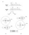
図3は、本実施の形態における位置測位システム10aの動作を示す図である。図3の(a)は、照明器具20a及び20bの夫々から送信される長距離用ビーコン及び短距離用ビーコンの送信タイミングを示すタイミングチャートである。図3の(a)において、縦軸は電波強度(つまり、送信電力)を示し、波高の高い矩形パルスが長距離用ビーコンの送信タイミングを示し、波高の低い矩形パルスが短距離用ビーコンの送信タイミングを示す。各パルスは、識別情報が送信されるタイミングに相当する。図3の(b)及び(c)は、夫々、図3の(a)に示されたタイミングチャートの時刻T1及び時刻T2におけるビーコンの送信範囲(つまり、ビーコンが届く範囲)を示す図である。図3の(b)及び(c)において、大きい半径の円は長距離用ビーコンが届く(つまり、受信できる)範囲を示し、小さい半径の円は短距離用ビーコンが届く(つまり、受信できる)範囲を示している。 FIG. 3 is a diagram illustrating an operation of the
ここで、照明器具20a及び20bは、一方が短距離用ビーコンを送信しているときに他方が長距離用ビーコンを送信しても両ビーコンが干渉し合うことがないが、双方が長距離用ビーコンを送信したときには両ビーコンが干渉し合う程度に接近して設置されている。 Here, the
図3の(a)に示されるように、照明器具20a及び20bの夫々において、ビーコン送信部50は、長距離用ビーコン及び短距離用ビーコンを、時分割で、間欠的に、繰り返し、送信する。本実施の形態では、照明器具20a及び20bは、1回の長距離用ビーコンを送信した後に2回の短距離用ビーコンを送信することを繰り返す。このように、照明器具20a及び20bからは、長距離用ビーコンと短距離用ビーコンとが送信され、かつ、長距離用ビーコンが間欠的に送信されるので、ビーコンが干渉し合う確率が低くなり、かつ、ビーコンが端末装置14に受信される確率が上がる。 As shown in FIG. 3 (a), in each of the
さらに特徴的なことは、照明器具20a及び20bの一方から長距離用ビーコンが送信されているタイミングでは、他方から短距離用ビーコンが出力されている点である。つまり、図3の(a)における時刻T1では、照明器具20aから長距離用ビーコンが送信され、一方、照明器具20bから短距離用ビーコンが送信されている。これにより、図3の(b)に示されるように、時刻T1では、照明器具20aと照明器具20bとの間において、ビーコンが干渉し合うことがない。さらに、図3の(a)における時刻T2では、照明器具20aから短距離用ビーコンが送信され、一方、照明器具20bから長距離用ビーコンが送信されている。これにより、図3の(c)に示されるように、時刻T2では、照明器具20aと照明器具20bとの間において、ビーコンが干渉し合うことがない。 What is more characteristic is that at the timing when the long distance beacon is transmitted from one of the
なお、図3の(a)において、照明器具20a及び20bのいずれもが長距離用ビーコンを送信していないタイミング(例えば、双方が短距離用ビーコンを送信している期間)では、ビーコンが干渉し合うことがないのは言うまでもない。 In addition, in (a) of FIG. 3, a beacon interferes in the timing (for example, the period when both are transmitting the short distance beacon) in which neither of the
このように、本実施の形態では、照明器具20a及び20bの夫々のビーコン送信部50は、位置測位システム10aに用いられる他の照明器具が長距離用ビーコンを送信するタイミングと同期をとって長距離用ビーコンを送信する。より詳しくは、ビーコン送信部50は、他の照明器具が長距離用ビーコンを送信するタイミングと重ならないタイミングで、自器具から、長距離用ビーコンを送信する。このような制御は、照明器具20a及び20bの夫々のビーコン送信部50が、商用電源などの共通の交流電源16における予め定められた位相(照明器具20a及び20bの夫々に割り当てられた異なる位相)に同期してビーコンを送信することで実現される。あるいは、照明器具20a及び20bが共通の同期信号を受信し、予め設定された異なるタイミング(送信する順番)で、夫々のビーコン送信部50がビーコンを送信することで実現される。これにより、照明器具20a及び20bから送信される長距離用ビーコンが干渉し合うことが確実に回避される。よって、限られた場所に照明器具を接近して複数台設置することが可能になる。 Thus, in this Embodiment, each
以上のように、本実施の形態によれば、位置測位システム10aに用いられる照明器具20a及び20bは、電力を供給する電力供給部30と、電力供給部30から供給される電力で点灯する照明部40と、ビーコン送信部50とを備える。ビーコン送信部50は、電力供給部30から供給される電力で動作し、位置測位に用いられる信号であるビーコンを送信する。このとき、ビーコンには、第1送信電力で送信される長距離用ビーコンと、第1送信電力よりも小さい第2送信電力で送信される短距離用ビーコンとが含まれる。そして、ビーコン送信部50は、少なくとも長距離用ビーコンを間欠的に送信する。 As described above, according to the present embodiment, the
これにより、照明器具20a及び20bからは、長距離用ビーコンと短距離用ビーコンとが送信され、かつ、長距離用ビーコンが間欠的に送信されるので、ビーコンが干渉し合う確率が低くなり、かつ、ビーコンが端末装置14に受信される確率が上がる。よって、位置測位システムに用いられる照明器具であって限られた場所に複数台設置することが可能な照明器具、及び、それを用いた位置測位システムが実現される。 Thereby, since the long distance beacon and the short distance beacon are transmitted from the
また、ビーコン送信部50は、電波により、長距離用ビーコン及び短距離用ビーコンを送信する。これにより、例えば、BLEによる低消費電力の近距離無線通信を用いた位置測位が実現される。 Moreover, the
また、ビーコン送信部50は、位置測位システム10aに用いられる他の照明器具が長距離用ビーコンを送信するタイミングと同期をとって、自器具から長距離用ビーコンを送信する。より詳しくは、ビーコン送信部50は、他の照明器具が長距離用ビーコンを送信するタイミングと重ならないタイミングで、自器具から長距離用ビーコンを送信する。 Moreover, the
これにより、照明器具20a及び20bから送信される長距離用ビーコンが干渉し合うことが確実に回避される。よって、限られた場所に照明器具を接近して複数台設置することが可能になる。 Thereby, it is reliably avoided that the long distance beacons transmitted from the
なお、上記実施の形態では、照明器具20a及び20bが同期をとって長距離用ビーコンを送信したが、このような同期は必須ではない。同期をとらなくても、照明器具20a及び20bの夫々から長距離用ビーコンが間欠的に送信されるので、連続的に長距離用ビーコンが送信されるケースに比べ、ビーコンが干渉し合う確率は低くなる。ただし、照明器具20a及び20bが同期をとらずにビーコンを送信する場合には、同期をとる場合に比べ、照明器具20a及び20bにおける長距離用ビーコンの送信間隔をより長めに設定するのが好ましい。 In addition, in the said embodiment, although the
また、上記実施の形態において、ビーコン送信部50は、短距離用ビーコンを送信するときに、可視光、紫外光又は赤外光による光信号を送信してもよい。光信号としては、例えば、照明部40から照射される光の強度を変調することで得られる可視光通信用の光信号である。光信号を送信する場合には、ビーコン送信部50は、電波による短距離用ビーコンと並行して、短距離用ビーコンに含まれる識別情報と同じ又は異なる識別情報を含む光信号を送信してもよいし、電波による短距離用ビーコンに代えて光信号を送信してもよい。これにより、光信号を受信できる端末装置14を対象とする位置測位システムが実現される。 Moreover, in the said embodiment, the
また、上記実施の形態では、長距離用ビーコンと短距離用ビーコンとは、時分割で送信されたが、図4に示されるように、同時に送信されてもよい。図4は、上記実施の形態の変形例に係るビーコンの送信タイミングを示す図である。本図から分かるように、この送信タイミングでは、照明器具20a及び20bにおいて、短距離用ビーコンが連続的に送信されている。よって、長距離用ビーコンが送信されるタイミングでは、同時に、短距離用ビーコンも送信される。 Moreover, in the said embodiment, although the beacon for long distances and the beacon for short distances were transmitted by time division, you may transmit simultaneously, as FIG. 4 shows. FIG. 4 is a diagram illustrating beacon transmission timing according to a modification of the above embodiment. As can be seen from this figure, at this transmission timing, short distance beacons are continuously transmitted in the
このような変形例に係るビーコンの送信タイミングであっても、長距離用ビーコンが間欠的に送信されるので、照明器具20a及び20bからのビーコンが干渉し合う可能性が低い。あるいは、照明器具20a及び20bから同期して排他的なタイミングで長距離用ビーコンが送信される場合には、2つの長距離用ビーコンが干渉し合うことがない。 Even at the beacon transmission timing according to such a modification, since the long distance beacon is intermittently transmitted, the possibility that the beacons from the
(実施の形態2)
次に、本発明の実施の形態2における位置測位システムについて説明する。(Embodiment 2)
Next, the position positioning system in Embodiment 2 of this invention is demonstrated.
図5は、本発明の実施の形態2における位置測位システム10bの構成を示すブロック図である。位置測位システム10bは、端末装置14の位置測位だけでなく、非常時の安否確認を行うことができるシステムであり、複数の照明器具21a〜21cと、端末装置14とで構成される。なお、本実施の形態では、非常時とは、交流電源16から照明器具21a〜21cへの交流電力の供給が断たれる状態をいう。 FIG. 5 is a block diagram showing a configuration of
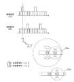
照明器具21a〜21cは、位置測位システムに用いられる照明器具(ここでは、非常灯又は誘導灯としての機能を有する照明器具)であり、少なくとも実施の形態1における照明器具20a及び20bが有する機能を備える。本実施の形態における照明器具21a〜21cは、図6の(a)又は(b)の外観図に示されるような照明器具であり、図5に示されるように、電力供給部30、照明部40、光通信部42、ビーコン送信部50、及び、点検ひも55を備える。なお、以下では、実施の形態1に比べて付加された機能、及び、実施の形態1と異なる点を中心に説明する。 The
電力供給部30は、交流電源16からの交流電力を直流電力に変換するだけでなく、蓄電池32を内蔵している。非常時には、電力供給部30は、交流電源16からの交流電力が断たれたことを検知し、照明部40、光通信部42及びビーコン送信部50に対して、内蔵の蓄電池32からの直流電力を供給すること、及び、非常時であることの通知を行う。 The
点検ひも55は、外部から指示(メンテナンス指示)を検知するための入力デバイスの一例であり、点検ひも55が引かれると、そのことが照明部40、光通信部42及びビーコン送信部50に通知される。 The
照明部40は、電力供給部30から供給される電力で点灯する光源である。本実施の形態では、照明部40は、通常時(非常時でない時)には照明用光源として機能(あるいは、消灯)し、非常時には、電力供給部30に内蔵された蓄電池32から供給される電力で点灯する非常灯又は誘導灯として機能する。なお、メンテナンス時(点検ひも55が引かれることでメンテナンス指示の通知を受けた時)には、照明部40は、非常時と同様の動作をする。 The
光通信部42は、照明部40から照射される光を変調することで光信号を送信する回路であり、非常時には、電力供給部30に内蔵された蓄電池32から供給される電力で動作する。光通信部42は、通常時には、予め定められた情報(例えば、ショッピング街でのお買い得情報)を光信号で送信する、あるいは、照明部40が消灯しているときには、動作を停止している。一方、非常時には、光通信部42は、蓄電池32からの電力供給の下で、光信号で非常用のメッセージを送信する。さらに、メンテナンス時には、光通信部42は、光信号でメンテナンス情報を送信する。ここで、「メンテナンス情報」とは、その照明器具のメンテナンスに必要な情報であり、例えば、照明部40の点灯状態、蓄電池32の充電状態、及び、ビーコン送信部50の状態の少なくとも一つを示す情報である。このようなメンテナンス情報は、光信号の受信機能を備える端末装置14に受信されて表示される。 The
なお、本実施の形態では、照明部40が通常時の光源、非常時の光源(非常灯又は誘導灯)、及び、光信号の送信機の機能を兼ねているが、これに代えて、あるいは、加えて、光通信部42が、通常時の光源、及び、光信号の送信機の機能を備えてもよい。 In the present embodiment, the
ビーコン送信部50は、実施の形態1におけるビーコン送信部50と同様の機能に加えて、非常時に、電力供給部30に内蔵された蓄電池32から供給される電力で動作する安否確認の機能を有する。つまり、ビーコン送信部50は、非常時には、端末装置14を所持する人の安否を確認するために、端末装置14から、端末装置14が保持する情報(例えば、端末装置14の通信アドレスなどの識別情報)を安否情報として取得する。そして、ビーコン送信部50は、アドホック通信により、取得した安否情報を、位置測位システムを構成する他の照明器具が備えるビーコン送信部50に伝達する。本実施の形態では、照明器具21aのビーコン送信部50は、取得した安否情報を照明器具21bのビーコン送信部50に伝達する。同様にして、照明器具21bのビーコン送信部50は、照明器具21a及び端末装置14から取得した安否情報を照明器具21cのビーコン送信部50に伝達する。そして、アドホック通信における最下流の照明器具21cでは、ビーコン送信部50は、インターネット23を介してサーバ24に安否情報を通知する。なお、メンテナンス時には、ビーコン送信部50は、非常時と同様の動作をする。 In addition to the same function as
サーバ24は、インターネット23を介して照明器具21cから安否情報を受信すると、安否情報に含まれる識別情報と安否確認者25の連絡先との対応を示すデータベース24aを参照することで、受信した安否情報に対応する安否確認者25の連絡先を特定する。そして、サーバ24は、特定した連絡先に、安否情報を取得できたことを通知する。これにより、安否確認者25は、非常時に、端末装置14を所持する人の安否を知ることができる。 When the
次に、以上のように構成された本実施の形態における位置測位システム10bの動作について説明する。 Next, the operation of the
図7は、本実施の形態における位置測位システム10bの動作を示す状態遷移図である。ここでは、位置測位システム10bにおける特徴的な照明器具21a〜21cの動作モードを示す状態遷移図が示されている。 FIG. 7 is a state transition diagram showing the operation of the
(1)通常時(S10)
交流電源16からの交流電力が供給される通常時においては、照明器具21a〜21cは、次の動作をする。(1) Normal time (S10)
In a normal time when AC power from the
つまり、照明部40は、交流電源16からの交流電力が電力供給部30で変換された直流電力の供給を受けて、実施の形態1と同様に、通常の照明用光源として機能する(あるいは、消灯している)。また、ビーコン送信部50は、交流電源16からの交流電力が電力供給部30で変換された直流電力の供給を受けて、実施の形態1と同様に、位置測位用のビーコン(長距離用ビーコン及び短距離用ビーコン)を送信する。さらに、光通信部42は、交流電源16からの交流電力が電力供給部30で変換された直流電力の供給を受けて、予め定められた情報(例えば、ショッピング街でのお買い得情報)を送信する。 That is, the illuminating
(2)非常時(S11)
交流電源16からの交流電力が断たれた非常時においては、照明器具21a〜21cは、次の動作をする。なお、非常時には、上述したように、電力供給部30は、交流電源16からの交流電力が断たれたことを検知し、照明部40、光通信部42及びビーコン送信部50に対して、内蔵の蓄電池32からの直流電力を供給すること、及び、非常時であることの通知を行う。(2) Emergency (S11)
In an emergency when the AC power from the
非常時においては、照明部40は、電力供給部30から非常時であることの通知を受けると、電力供給部30に内蔵された蓄電池32からの直流電力の供給を受けて、非常灯又は誘導灯として機能する。また、ビーコン送信部50は、電力供給部30から非常時であることの通知を受けると、電力供給部30に内蔵された蓄電池32からの直流電力の供給を受けて、安否確認の処理(上述した端末装置14からの安否情報の収集及び安否情報の伝達)を行う。さらに、光通信部42は、電力供給部30から非常時であることの通知を受けると、電力供給部30に内蔵された蓄電池32からの直流電力の供給を受けて、非常用のメッセージ(例えば、停電になったこと、及び、避難経路の情報)を送信する。 In an emergency, when the
なお、停電から復帰し、交流電源16からの交流電力の供給が再開されると、照明器具21a〜21cは、通常時の動作をする(S10)。 In addition, if it recovers from a power failure and supply of the alternating current power from the alternating
(3)メンテナンス時(S12)
点検ひも55が引かれることでメンテナンス指示が与えられた場合には、照明器具21a〜21cは、次の動作をする。(3) During maintenance (S12)
When the maintenance instruction is given by pulling the
照明部40は、メンテナンス指示の通知を受けると、診断のための動作として、非常時と同様の動作をする。たとえば、照明部40は、電力供給部30に内蔵された蓄電池32から供給される電力で点灯する非常灯又は誘導灯として機能する。また、ビーコン送信部50も、メンテナンス指示の通知を受けると、診断のための動作として、非常時と同様の動作をする。つまり、ビーコン送信部50は、電力供給部30に内蔵された蓄電池32からの直流電力の供給を受けて、安否確認の処理を行う。さらに、光通信部42は、メンテナンス指示の通知を受けると、メンテナンス情報を送信する。 When receiving the notification of the maintenance instruction, the
なお、点検ひも55が、再度、引かれた場合には、そのことが照明部40、光通信部42及びビーコン送信部50に通知され、照明部40、光通信部42及びビーコン送信部50(つまり、照明器具21a〜21c)は、通常時の動作をする(S10)。 When the
以上のように、本実施の形態における位置測位システム10bの照明器具21a〜21cは、実施の形態1の機能に加えて、以下の機能を備える。つまり、電力供給部30は、蓄電池32を有し、照明部40は、蓄電池32から供給される電力で点灯する非常灯又は誘導灯として機能する。ビーコン送信部50は、端末装置14を所持する人の安否を確認するために、端末装置14から、端末装置14が保持する情報を安否情報として取得し、取得した安否情報を、位置測位システム10bを構成する他の照明器具が備えるビーコン送信部50に伝達する。 As mentioned above, in addition to the function of Embodiment 1, the
これにより、停電などの非常時には、非常灯又は誘導灯として照明され、かつ、その場にいる人(その人が保持する端末装置14)の情報が安否情報として収集されて安否確認者25に通知される。 Thereby, in the event of an emergency such as a power outage, information on a person who is illuminated as an emergency light or a guide light and is present (the
また、本実施の形態では、実施の形態1の構成に、さらに、照明部40から照射される光を変調することで光信号を送信する光通信部42が備えられる。そして、その光通信部42は、外部からのメンテナンス指示を検知した場合に、照明部40の点灯状態、蓄電池32の充電状態、及び、ビーコン送信部50の状態の少なくとも一つを示すメンテナンス情報を光信号で送信する。 Moreover, in this Embodiment, the
これにより、メンテナンス時には、点検ひも55を引くだけで、光信号を受信できる端末装置14を用いて、照明器具21a〜21cの詳細なメンテナンス情報を容易に取得できる。よって、照明器具21a〜21cのメンテナンス作業が、目視による作業に比べ、より迅速になり、かつ、正確になる。 Thereby, at the time of a maintenance, the detailed maintenance information of the
(実施の形態3)
次に、本発明の実施の形態3における照明器具について説明する。(Embodiment 3)
Next, the lighting fixture in Embodiment 3 of this invention is demonstrated.
図8は、本発明の実施の形態3における照明器具22の構成を示すブロック図である。照明器具22は、実施の形態1又は2に示される位置測位システムにも用いられる照明器具であり、実施の形態1における照明器具20a及び20bが有する機能に加えて、災害時における動作モードを有する。具体的には、本実施の形態における照明器具22は、図8に示されるように、電力供給部30、照明部40、光通信部42、ビーコン送信部50、災害検知部60、及び、制御部62を備える。以下、実施の形態1に比べて付加された機能、及び、実施の形態1と異なる点を中心に説明する。 FIG. 8 is a block diagram showing a configuration of the
電力供給部30は、実施の形態1と同様の回路であり、本実施の形態では、照明部40、光通信部42及びビーコン送信部50に加えて、災害検知部60及び制御部62にも電力を供給する。 The
照明部40は、実施の形態1と同様の光源であり、本実施の形態では、実施の形態2と同様に、通常の照明光に加えて、光通信部42からの変調信号に基づく強度変調をした光信号も発する。 The
光通信部42は、照明部40から照射される光を変調することで光信号を送信する回路である。 The
ビーコン送信部50は、実施の形態1におけるビーコン送信部50と同様の機能を有する。ただし、本実施の形態では、ビーコン送信部50は、BLEなどの電波によるビーコン(電波ビーコン)を送信する。
災害検知部60は、電力供給部30から供給される電力で動作し、災害の発生を検知する回路である。災害検知部60は、例えば、Wi−Fi(登録商標)又は3G(第3世代携帯電話方式)などの電波によって災害情報を取得し、取得した災害情報を検知信号として制御部に出力する通信回路である。 The
制御部62は、電力供給部30から供給される電力で動作し、災害検知部60での検知に応じた動作モード(通常モード及び災害モード)で光通信部42及びビーコン送信部50の動作を制御する回路である。制御部62は、例えば、制御プログラムを内蔵した1チップマイコンなどで実現される。 The
より詳しくは、制御部62は、災害検知部60で災害が検知されていない場合には、通常モードとして予め定められた動作モードで光通信部42及びビーコン送信部50を動作させる。一方、災害検知部60で災害が検知された場合には、制御部62は、災害モードとして予め定められた動作モードで光通信部42及びビーコン送信部50を動作させる。 More specifically, when no disaster is detected by the
具体的には、制御部62は、災害モードでは、ビーコン送信部50に対して、次の制御を行う。つまり、制御部62は、電波ビーコンに、災害に対応づけられた識別情報を含ませて、電波ビーコンが届く範囲内にある端末装置14にプッシュ通信するように、ビーコン送信部50を動作させる。災害に対応づけられた識別情報は、例えば、光通信部42からの光信号を取得できる場所に端末装置14を移動させるメッセージを端末装置14に表示させるための識別情報である。 Specifically, the
また、制御部62は、災害モードでは、光通信部42に対して、次の制御を行う。つまり、制御部62は、光信号に、災害検知部60で検知された災害の種別に対応づけられた識別情報を含ませて、端末装置14に送信するように、光通信部42を動作させる。たとえば、制御部62は、光信号に、災害対応時のマニュアルを端末装置14に表示させるための識別情報を含ませて、端末装置14に送信するように、光通信部42を動作させる。 Further, the
次に、以上のように構成された本実施の形態における照明器具22の動作について説明する。 Next, operation | movement of the
図9は、本実施の形態における照明器具22の動作モードを示す状態遷移図である。 FIG. 9 is a state transition diagram showing an operation mode of the
(1)通常モード(S15)
災害検知部60で災害が検知されていない場合には、制御部62は、次の制御を行う。(1) Normal mode (S15)
When no disaster is detected by the
つまり、制御部62は、光通信部42に対して、通常モード時に送信する情報として予め定められた識別情報(つまり、一般情報用ID)を光信号として送信させる制御をする。この識別情報を受信した端末装置14は、アプリケーションの実行に従って、受信した識別情報に対応する動作(例えば、ショッピング街でのお買い得情報の表示)をする。 That is, the
また、制御部62は、ビーコン送信部50に対して、位置測位に必要な識別情報(位置測位用ID)を電波ビーコンとして送信させる制御をする。この識別情報を受信した端末装置14は、アプリケーションの実行に従って、内部に保持するテーブルを参照、又は、インターネットを介して位置測位用のサーバに問い合わせることで、受信した識別情報に対応する現在位置を取得し、表示する。 Further, the
なお、この通常モードでは、光通信部42及びビーコン送信部50の少なくとも一方の動作が停止(あるいは、電源OFF(電力供給されない状態))していてもよい。 In this normal mode, the operation of at least one of the
(2)災害モード(S16)
災害検知部60で災害が検知された場合には、制御部62は、次の制御を行う。(2) Disaster mode (S16)
When a disaster is detected by the
つまり、制御部62は、光通信部42に対して、災害検知部60で検知された災害の種別に対応づけられた識別情報(つまり、災害情報用ID)を含む光信号を送信させる制御をする。この識別情報を受信した端末装置14は、アプリケーションの実行に従って、受信した識別情報に対応する動作(例えば、災害が発生したこと、及び、発生した災害の種類の表示)をする。 That is, the
また、制御部62は、ビーコン送信部50に対して、災害に対応づけられた識別情報(つまり、災害用ID)を含む電波ビーコンを送信させる制御をする。この識別情報を受信した端末装置14は、アプリケーションの実行に従って、光通信部42からの光信号を取得できる場所に端末装置14を移動させるメッセージを端末装置14に表示する。 The
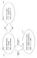
図10は、本実施の形態における照明器具22の動作を示すフローチャートである。また、図11は、本実施の形態における照明器具22からの電波ビーコン又は光信号を受信した端末装置14の画面表示例を示す図である。 FIG. 10 is a flowchart showing the operation of the
災害検知部60が災害を検知すると(S20)、制御部62は、動作モードを通常モードから災害モードに遷移させ(S21)、ビーコン送信部50に対して、災害に対応づけられた識別情報を含む電波ビーコンを送信させる制御をする(S22)。これにより、端末装置14は、通常モードにおける位置測位の結果を示す画面表示(図11の(a))から、光通信部42からの光信号を取得できる場所に端末装置14を移動させるメッセージを表示する災害モードにおける画面表示(図11の(b))に切り替える。 When the
そして、制御部62は、災害検知部60で検知された災害の種別を判定し(S23)、光通信部42に対して、判定した災害の種別に対応する動作をさせる(S24〜S29)。具体的には、制御部62は、災害検知部60で検知された災害が火災である場合には、火災モードに対応する識別情報を決定し(S24)、その識別情報を含む光信号を送信するように光通信部42を制御する(S25)。なお、制御部62は、識別情報の決定においては、災害モードと識別情報との対応を予め登録したテーブルを参照する。また、災害検知部60で検知された災害が地震である場合には、制御部62は、地震モードに対応する識別情報を決定し(S26)、その識別情報を含む光信号を送信するように光通信部42を制御する(S27)。また、災害検知部60で検知された災害が津波である場合には、制御部62は、津波モードに対応する識別情報を決定し(S28)、その識別情報を含む光信号を送信するように光通信部42を制御する(S29)。 Then, the
これにより、各災害モードに対応する識別情報を受信した端末装置14は、アプリケーションの実行に従って、受信した識別情報に対応する画面表示をする。たとえば、火災モードに対応する識別情報を受信した端末装置14は、既に判明している現在位置に基づいて避難経路を特定し、画面に表示する(図11の(c))。また、地震モードに対応する識別情報を受信した端末装置14は、予め作成された災害対応時のマニュアルを画面に表示する(図11の(d))。なお、端末装置14での画面表示は、アプリケーションの実行の下、あるいは、端末装置14での初期設定で予め設定された言語(日本語、英語など)で、行われる。 Thereby, the
そして、制御部62は、災害検知部60での検知状況を参照することで、検知された災害が収束したかどうかを判断し(S30)、収束したと判断するまで、判断を繰り返す(S30でno)。収束したと判断した場合には(S30でyes)、制御部62は、動作モードをこれまでの災害モードから通常モードに遷移させる(S31)。 Then, the
以上のように、本実施の形態における照明器具22は、実施の形態1の機能に加えて、以下の機能を備える。つまり、照明器具22は、さらに、照明部40から照射される光を変調することで光信号を送信する光通信部42と、災害の発生を検知する災害検知部60と、動作モードを制御する制御部62とを備える。制御部62は、災害検知部60で災害が検知されていない場合に、通常モードとして予め定められた動作モードで光通信部42及びビーコン送信部50を動作させる。一方、災害検知部60で災害が検知された場合には、制御部62は、災害モードとして予め定められた動作モードで光通信部42及びビーコン送信部50を動作させる。これにより、通常モードと災害モードの2つの動作モードに対応した位置測位システムが実現される。 As described above, the
また、ビーコン送信部50は、電波ビーコンを送信し、制御部62は、災害モードでは、電波ビーコンに、災害に対応づけられた識別情報を含ませて、電波ビーコンが届く範囲内にある端末装置にプッシュ通信するように、ビーコン送信部50を動作させる。これにより、災害発生時に、電波ビーコンによって端末装置に対してプッシュ通信が行われ、端末装置に対して災害の発生が通知される。 In addition, the
また、災害に対応づけられた識別情報は、光通信部42からの光信号を取得できる場所に端末装置を移動させるメッセージを端末装置14に表示させるための識別情報である。これにより、災害時には、電波ビーコンを受信した端末装置14の画面に、光通信部42からの光信号を取得できる場所に端末装置を移動させるメッセージが表示される。 The identification information associated with the disaster is identification information for causing the
そして、制御部62は、災害モードでは、光信号に、災害検知部60で検知された災害の種別に対応づけられた識別情報を含ませて、端末装置14に送信するように、光通信部42を動作させる。これにより、災害の種別に対応づけられた識別情報を受信した端末装置14の画面には、災害の種別に応じた画像又はメッセージが表示され、災害時に被災者の誘導が適切に行われる。 In the disaster mode, the
また、制御部62は、災害モードでは、光信号に、災害対応時のマニュアルを端末装置14に表示させるための識別情報を含ませて、端末装置に送信するように、光通信部を動作させる。これにより、災害が発生した時に、この識別情報を受信した端末装置14の画面には災害対応時のマニュアルが表示され、災害時に被災者に対して適切な指示が与えられる。 Further, in the disaster mode, the
以上、本発明に係る照明器具及び位置測位システムについて、実施の形態1〜3及び変形例に基づいて説明したが、本発明は、これらの実施の形態及び変形例に限定されない。本発明の趣旨を逸脱しない限り、当業者が思いつく各種変形を実施の形態又は変形例に施したもの、及び、実施の形態及び変形例における任意の構成要素を組み合わせて実現される形態も、本発明の範囲内に含まれてもよい。 As mentioned above, although the lighting fixture and position positioning system which concern on this invention were demonstrated based on Embodiment 1-3 and the modification, this invention is not limited to these embodiment and the modification. Unless it deviates from the gist of the present invention, various modifications conceived by those skilled in the art have been made in the embodiments or modifications, and forms realized by combining arbitrary components in the embodiments and modifications are also described in this document. It may be included within the scope of the invention.
たとえば、上記実施の形態1〜3では、ビーコン送信部50は、電波によるビーコン(電波ビーコン)を送信したが光信号によるビーコン(光ビーコン)を送信してもよい。このとき、長距離用ビーコン及び短距離用ビーコンの一方が電波ビーコンであり、他方が光ビーコンであってもよい。 For example, in the first to third embodiments, the
また、光通信部42は、照明部40から照射される光を利用した可視光通信用の光信号を送信したが、赤外光又は紫外光による光信号を送信してもよい。 Moreover, although the
また、上記実施の形態2及び3では、実施の形態1の全ての機能が備えられたが、各実施の形態における効果が奏される限り、実施の形態1の全ての機能が備えられなくてもよい。たとえば、実施の形態2及び3では、ビーコン送信部は、必ずしも、長距離用ビーコン及び短距離用ビーコンを送信しなくてもよく、一種類のビーコンを送信してもよい。そのような構成であっても、実施の形態2における安否確認、及び、実施の形態3における災害モード時の動作は実現されるからである。 In the second and third embodiments, all the functions of the first embodiment are provided. However, all the functions of the first embodiment are not provided as long as the effects of the respective embodiments are achieved. Also good. For example, in Embodiments 2 and 3, the beacon transmission unit does not necessarily have to transmit the long distance beacon and the short distance beacon, and may transmit one type of beacon. This is because even with such a configuration, the safety confirmation in the second embodiment and the operation in the disaster mode in the third embodiment are realized.
10a、10b 位置測位システム
14 端末装置
20a、20b、21a〜21c、22 照明器具
30 電力供給部
32 蓄電池
40 照明部
42 光通信部
50 ビーコン送信部
60 災害検知部
62 制御部10a,
Claims (14)
Translated fromJapanese電力を供給する電力供給部と、
前記電力供給部から供給される電力で点灯する照明部と、
前記電力供給部から供給される電力で動作し、位置測位に用いられる信号であるビーコンを送信するビーコン送信部とを備え、
前記ビーコンには、第1送信電力で送信される長距離用ビーコンと、前記第1送信電力よりも小さい第2送信電力で送信される短距離用ビーコンとが含まれ、
前記ビーコン送信部は、少なくとも前記長距離用ビーコンを間欠的に送信する
照明器具。A lighting fixture used in a positioning system,
A power supply unit for supplying power;
An illumination unit that is lit by power supplied from the power supply unit;
A beacon transmitter that operates with power supplied from the power supply unit and transmits a beacon that is a signal used for position measurement,
The beacon includes a long distance beacon transmitted at a first transmission power and a short distance beacon transmitted at a second transmission power smaller than the first transmission power,
The beacon transmitting unit intermittently transmits at least the long distance beacon.
請求項1記載の照明器具。The lighting apparatus according to claim 1, wherein the beacon transmission unit transmits the long-distance beacon and the short-distance beacon by radio waves.
請求項1又は2記載の照明器具。The lighting apparatus according to claim 1, wherein the beacon transmission unit transmits an optical signal using visible light, ultraviolet light, or infrared light when transmitting the short-range beacon.
請求項1〜3のいずれか1項に記載の照明器具。The said beacon transmission part transmits the said beacon for long distances synchronizing with the timing which the other lighting fixture used for the said positioning system transmits the beacon for long distances. The luminaire described.
請求項4記載の照明器具。The lighting apparatus according to claim 4, wherein the beacon transmission unit transmits the long distance beacon at a timing that does not overlap with a timing at which the other lighting apparatus transmits the long distance beacon.
前記照明部は、前記蓄電池から供給される電力で点灯する非常灯又は誘導灯であり、
前記ビーコン送信部は、端末装置を所持する人の安否を確認するために、前記端末装置から、前記端末装置が保持する情報を安否情報として取得し、取得した前記安否情報を、前記位置測位システムを構成する他の照明器具が備えるビーコン送信部に伝達する
請求項1〜5のいずれか1項に記載の照明器具。The power supply unit has a storage battery,
The illuminating unit is an emergency light or a guide light that is lit with electric power supplied from the storage battery,
The beacon transmission unit acquires information held by the terminal device as safety information from the terminal device to confirm the safety of the person who owns the terminal device, and the acquired safety information is used as the position measurement system. The luminaire according to claim 1, which is transmitted to a beacon transmission unit included in another luminaire that constitutes the luminaire.
前記光通信部は、前記照明部の点灯状態、前記蓄電池の充電状態、及び、前記ビーコン送信部の状態の少なくとも一つを示すメンテナンス情報を前記光信号で送信する
請求項6記載の照明器具。And an optical communication unit that transmits an optical signal by modulating light emitted from the illumination unit,
The lighting apparatus according to claim 6, wherein the optical communication unit transmits maintenance information indicating at least one of a lighting state of the lighting unit, a charged state of the storage battery, and a state of the beacon transmission unit using the optical signal.
請求項7記載の照明器具。The lighting apparatus according to claim 7, wherein the optical communication unit transmits the maintenance information as the optical signal when an instruction from the outside is detected.
前記照明部から照射される光を変調することで光信号を送信する光通信部と、
災害の発生を検知する災害検知部と、
前記災害検知部で災害が検知されていない場合に、通常モードとして予め定められた動作モードで前記光通信部及び前記ビーコン送信部を動作させ、前記災害検知部で災害が検知された場合に、災害モードとして予め定められた動作モードで前記光通信部及び前記ビーコン送信部を動作させる制御部とを備える
請求項1〜5のいずれか1項に記載の照明器具。further,
An optical communication unit that transmits an optical signal by modulating light emitted from the illumination unit;
A disaster detection unit that detects the occurrence of a disaster;
When no disaster is detected by the disaster detection unit, the optical communication unit and the beacon transmission unit are operated in a predetermined operation mode as a normal mode, and when a disaster is detected by the disaster detection unit, The lighting apparatus according to claim 1, further comprising a control unit that operates the optical communication unit and the beacon transmission unit in an operation mode predetermined as a disaster mode.
前記制御部は、前記災害モードでは、前記電波ビーコンに、災害に対応づけられた識別情報を含ませて、前記電波ビーコンが届く範囲内にある端末装置にプッシュ通信をするように、前記ビーコン送信部を動作させる
請求項9記載の照明器具。The beacon transmission unit transmits a radio beacon,
In the disaster mode, the control unit includes the identification information associated with the disaster in the radio beacon, and performs the beacon transmission so as to perform push communication to a terminal device within the reach of the radio beacon. The lighting apparatus according to claim 9, wherein the unit is operated.
請求項10記載の照明器具。The identification information associated with the disaster is identification information for causing the terminal device to display a message for moving the terminal device to a place where the optical signal from the optical communication unit can be acquired. lighting equipment.
請求項11記載の照明器具。In the disaster mode, the control unit includes identification information associated with a type of disaster detected by the disaster detection unit in the optical signal, and transmits the identification information to the terminal device. The lighting fixture according to claim 11, wherein the unit is operated.
請求項11又は12記載の照明器具。In the disaster mode, the control unit includes the optical communication unit so that the optical signal includes identification information for causing the terminal device to display a disaster response manual and transmits the information to the terminal device. The lighting fixture according to claim 11 or 12, wherein the lighting fixture is operated.
前記照明器具から送信されるビーコンを受信し、受信した前記ビーコンを用いて位置測位を行う端末装置と
を備える位置測位システム。The lighting fixture according to any one of claims 1 to 13,
A position positioning system comprising: a terminal device that receives a beacon transmitted from the lighting fixture and performs position positioning using the received beacon.
Priority Applications (2)
| Application Number | Priority Date | Filing Date | Title |
|---|---|---|---|
| JP2014183691AJP6452030B2 (en) | 2014-09-09 | 2014-09-09 | Lighting equipment and positioning system |
| US14/823,195US9746542B2 (en) | 2014-09-09 | 2015-08-11 | Lighting apparatus and positioning system |
Applications Claiming Priority (1)
| Application Number | Priority Date | Filing Date | Title |
|---|---|---|---|
| JP2014183691AJP6452030B2 (en) | 2014-09-09 | 2014-09-09 | Lighting equipment and positioning system |
Publications (2)
| Publication Number | Publication Date |
|---|---|
| JP2016057166Atrue JP2016057166A (en) | 2016-04-21 |
| JP6452030B2 JP6452030B2 (en) | 2019-01-16 |
Family
ID=55438524
Family Applications (1)
| Application Number | Title | Priority Date | Filing Date |
|---|---|---|---|
| JP2014183691AExpired - Fee RelatedJP6452030B2 (en) | 2014-09-09 | 2014-09-09 | Lighting equipment and positioning system |
Country Status (2)
| Country | Link |
|---|---|
| US (1) | US9746542B2 (en) |
| JP (1) | JP6452030B2 (en) |
Cited By (10)
| Publication number | Priority date | Publication date | Assignee | Title |
|---|---|---|---|---|
| JP2018067295A (en)* | 2017-07-11 | 2018-04-26 | オカムラ印刷株式会社 | Watching system, watching method, information acquisition device, information processing device, method for those, and program |
| WO2018123957A1 (en)* | 2016-12-28 | 2018-07-05 | 日本電産株式会社 | Radiation device, positioning system, alarm system, sound pickup system, and display system |
| JP2019016917A (en)* | 2017-07-06 | 2019-01-31 | 株式会社Where | Control arrangement, control method, control program |
| JP2019033032A (en)* | 2017-08-09 | 2019-02-28 | パナソニックIpマネジメント株式会社 | Illumination system, radio controller, control method, and program |
| JP2019133743A (en)* | 2018-01-29 | 2019-08-08 | 東芝ライテック株式会社 | Lighting device |
| JP2019175796A (en)* | 2018-03-29 | 2019-10-10 | 東芝ライテック株式会社 | Illumination device |
| JP2020021720A (en)* | 2018-08-04 | 2020-02-06 | 浜井電球工業株式会社 | Guest room LED tube type camera system, lighting / surveillance system for travel guest rooms using it |
| KR102138478B1 (en)* | 2019-11-20 | 2020-07-27 | 김용석 | Smoke detection fire disaster prevention system |
| JP2022039644A (en)* | 2020-08-28 | 2022-03-10 | アイリスオーヤマ株式会社 | Illumination system |
| JP2022158084A (en)* | 2021-04-01 | 2022-10-14 | 株式会社遠藤照明 | Lighting system and lighting fixture |
Families Citing this family (20)
| Publication number | Priority date | Publication date | Assignee | Title |
|---|---|---|---|---|
| TR201910930T4 (en)* | 2015-07-31 | 2019-08-21 | Inventio Ag | Evacuation of buildings with elevator systems. |
| DE102015119626A1 (en)* | 2015-11-13 | 2017-05-18 | Osram Gmbh | Illuminating device with directional radio signal for position identification |
| DE102016104485A1 (en)* | 2016-03-11 | 2017-09-14 | Osram Gmbh | Lighting device with current limitation for communication device |
| DE102016104484A1 (en)* | 2016-03-11 | 2017-09-14 | Osram Gmbh | Lighting device with communication device |
| DE102016104486A1 (en)* | 2016-03-11 | 2017-09-14 | Osram Gmbh | Illumination system with signaling of a communication connection |
| US20180375576A1 (en)* | 2016-09-23 | 2018-12-27 | Osram Sylvania Inc. | Techniques for indoor navigation with emergency assistance via light-based communication |
| DE102016121663A1 (en)* | 2016-11-11 | 2018-05-17 | Osram Gmbh | Activating a transmitting device of a lighting device |
| ES2847257T3 (en) | 2016-11-11 | 2021-08-02 | Carrier Corp | High sensitivity fiber optic based detection |
| CN107124222B (en)* | 2017-04-20 | 2019-08-30 | 上海第二工业大学 | A time-of-arrival measurement system and method including a two-way visible light communication link |
| JP6899549B2 (en)* | 2017-05-25 | 2021-07-07 | パナソニックIpマネジメント株式会社 | Lighting devices, lighting fixtures, and signboards |
| EP3677099A4 (en) | 2017-08-28 | 2021-05-12 | Indoorsights Limited | LIGHTING COMMUNICATION, DETECTION AND / OR LOCATION DEVICE AND SYSTEM |
| US12156316B2 (en) | 2017-08-28 | 2024-11-26 | Indoorsights Limited | Facility communication and/or location apparatus and system |
| WO2019097891A1 (en)* | 2017-11-15 | 2019-05-23 | パナソニックIpマネジメント株式会社 | Wireless communication system and transmission terminal |
| CN109217925B (en)* | 2018-01-17 | 2021-04-09 | 北京石头世纪科技股份有限公司 | Near-field distance adjustment method, system, storage medium and electronic device for charging pile |
| GB201814254D0 (en)* | 2018-09-03 | 2018-10-17 | Purelifi Ltd | Pe959147gb |
| US10893598B2 (en)* | 2019-01-25 | 2021-01-12 | Osram Sylvania Inc. | Transmission of luminaire maintenance information |
| CN110177334A (en)* | 2019-05-23 | 2019-08-27 | 浙江台谊消防设备有限公司 | Personnel location system and method based on wearing bracelet and emergency luminaire |
| NL2023258B1 (en)* | 2019-06-04 | 2020-12-11 | Euro Sino Optical Res And Development Centre B V | Electronic Device For Li-Fi Communication And Geolocation |
| US11255946B2 (en)* | 2020-04-09 | 2022-02-22 | Trusteees Of Boston University | Apparatus and method for zone-based positioning |
| WO2022144320A1 (en)* | 2021-01-04 | 2022-07-07 | Signify Holding B.V. | An optical wireless communication system |
Citations (7)
| Publication number | Priority date | Publication date | Assignee | Title |
|---|---|---|---|---|
| JPH02179489A (en)* | 1988-12-30 | 1990-07-12 | Nec Home Electron Ltd | Transmitter controller |
| JP2005218066A (en)* | 2004-02-02 | 2005-08-11 | Nakagawa Kenkyusho:Kk | Positional information communication device |
| JP2006293774A (en)* | 2005-04-12 | 2006-10-26 | Fujitsu Ltd | Disaster prevention equipment and disaster prevention information management system |
| US20090138353A1 (en)* | 2005-05-09 | 2009-05-28 | Ehud Mendelson | System and method for providing alarming notification and real-time, critical emergency information to occupants in a building or emergency designed area and evacuation guidance system to and in the emergency exit route |
| JP2009206620A (en)* | 2008-02-26 | 2009-09-10 | Panasonic Electric Works Co Ltd | Optical transmission system |
| JP2009222417A (en)* | 2008-03-13 | 2009-10-01 | Ricoh Co Ltd | Position detection system, sending device, position detection method, and position detection program |
| JP2014001987A (en)* | 2012-06-15 | 2014-01-09 | Ricoh Co Ltd | Position detection system and position detection method |
Family Cites Families (13)
| Publication number | Priority date | Publication date | Assignee | Title |
|---|---|---|---|---|
| FI109496B (en)* | 1992-08-18 | 2002-08-15 | Nokia Corp | Apparatus and method for arranging a digital infrared coupled data transmission between the base part of a radio telephone apparatus and another apparatus |
| JP4375226B2 (en) | 2004-12-17 | 2009-12-02 | 沖電気工業株式会社 | Wireless communication apparatus and network system |
| JP2007266794A (en) | 2006-03-28 | 2007-10-11 | Matsushita Electric Works Ltd | Visible light communication system |
| JP5029186B2 (en) | 2007-07-19 | 2012-09-19 | 富士通株式会社 | POSITION CALCULATION DEVICE, POSITION CALCULATION PROGRAM, RECORDING MEDIUM, AND POSITION CALCULATION METHOD |
| JP2009053118A (en) | 2007-08-28 | 2009-03-12 | Panasonic Electric Works Co Ltd | Direction identification system |
| JP4925064B2 (en) | 2008-01-21 | 2012-04-25 | 日本信号株式会社 | Position detection system |
| US9386666B2 (en)* | 2011-06-30 | 2016-07-05 | Lutron Electronics Co., Inc. | Method of optically transmitting digital information from a smart phone to a control device |
| US9723676B2 (en)* | 2011-07-26 | 2017-08-01 | Abl Ip Holding Llc | Method and system for modifying a beacon light source for use in a light based positioning system |
| GB201117723D0 (en)* | 2011-10-13 | 2011-11-23 | Sensewhere Ltd | Method of estimating the position of a user device using radio beacons and radio beacons adapted to facilitate the methods of the invention |
| US20140249928A1 (en)* | 2013-02-01 | 2014-09-04 | Shelfbucks | Shelf to consumer platform |
| US9241353B2 (en)* | 2013-07-26 | 2016-01-19 | Qualcomm Incorporated | Communications between a mobile device and an access point device |
| US9317976B2 (en)* | 2013-10-29 | 2016-04-19 | Cubic Corporation | Fare collection using wireless beacons |
| WO2015077767A1 (en)* | 2013-11-25 | 2015-05-28 | Daniel Ryan | System and method for communication with a mobile device via a positioning system including rf communication devices and modulated beacon light sources |
- 2014
- 2014-09-09JPJP2014183691Apatent/JP6452030B2/ennot_activeExpired - Fee Related
- 2015
- 2015-08-11USUS14/823,195patent/US9746542B2/enactiveActive
Patent Citations (7)
| Publication number | Priority date | Publication date | Assignee | Title |
|---|---|---|---|---|
| JPH02179489A (en)* | 1988-12-30 | 1990-07-12 | Nec Home Electron Ltd | Transmitter controller |
| JP2005218066A (en)* | 2004-02-02 | 2005-08-11 | Nakagawa Kenkyusho:Kk | Positional information communication device |
| JP2006293774A (en)* | 2005-04-12 | 2006-10-26 | Fujitsu Ltd | Disaster prevention equipment and disaster prevention information management system |
| US20090138353A1 (en)* | 2005-05-09 | 2009-05-28 | Ehud Mendelson | System and method for providing alarming notification and real-time, critical emergency information to occupants in a building or emergency designed area and evacuation guidance system to and in the emergency exit route |
| JP2009206620A (en)* | 2008-02-26 | 2009-09-10 | Panasonic Electric Works Co Ltd | Optical transmission system |
| JP2009222417A (en)* | 2008-03-13 | 2009-10-01 | Ricoh Co Ltd | Position detection system, sending device, position detection method, and position detection program |
| JP2014001987A (en)* | 2012-06-15 | 2014-01-09 | Ricoh Co Ltd | Position detection system and position detection method |
Cited By (15)
| Publication number | Priority date | Publication date | Assignee | Title |
|---|---|---|---|---|
| WO2018123957A1 (en)* | 2016-12-28 | 2018-07-05 | 日本電産株式会社 | Radiation device, positioning system, alarm system, sound pickup system, and display system |
| JP2019016917A (en)* | 2017-07-06 | 2019-01-31 | 株式会社Where | Control arrangement, control method, control program |
| JP2018067295A (en)* | 2017-07-11 | 2018-04-26 | オカムラ印刷株式会社 | Watching system, watching method, information acquisition device, information processing device, method for those, and program |
| JP2019033032A (en)* | 2017-08-09 | 2019-02-28 | パナソニックIpマネジメント株式会社 | Illumination system, radio controller, control method, and program |
| JP2019133743A (en)* | 2018-01-29 | 2019-08-08 | 東芝ライテック株式会社 | Lighting device |
| JP7020241B2 (en) | 2018-03-29 | 2022-02-16 | 東芝ライテック株式会社 | Lighting equipment |
| JP2019175796A (en)* | 2018-03-29 | 2019-10-10 | 東芝ライテック株式会社 | Illumination device |
| JP2020021720A (en)* | 2018-08-04 | 2020-02-06 | 浜井電球工業株式会社 | Guest room LED tube type camera system, lighting / surveillance system for travel guest rooms using it |
| KR102138478B1 (en)* | 2019-11-20 | 2020-07-27 | 김용석 | Smoke detection fire disaster prevention system |
| JP2022039644A (en)* | 2020-08-28 | 2022-03-10 | アイリスオーヤマ株式会社 | Illumination system |
| JP2023101742A (en)* | 2020-08-28 | 2023-07-21 | アイリスオーヤマ株式会社 | Lighting fixture and lighting system |
| JP7418880B2 (en) | 2020-08-28 | 2024-01-22 | アイリスオーヤマ株式会社 | Luminaires and lighting systems |
| JP7491564B2 (en) | 2020-08-28 | 2024-05-28 | アイリスオーヤマ株式会社 | Lighting System |
| JP2022158084A (en)* | 2021-04-01 | 2022-10-14 | 株式会社遠藤照明 | Lighting system and lighting fixture |
| JP7487138B2 (en) | 2021-04-01 | 2024-05-20 | 株式会社遠藤照明 | Lighting systems and lighting fixtures |
Also Published As
| Publication number | Publication date |
|---|---|
| US20160072581A1 (en) | 2016-03-10 |
| US9746542B2 (en) | 2017-08-29 |
| JP6452030B2 (en) | 2019-01-16 |
Similar Documents
| Publication | Publication Date | Title |
|---|---|---|
| JP6452030B2 (en) | Lighting equipment and positioning system | |
| US9397709B2 (en) | Light device and positional information management system | |
| KR101175996B1 (en) | Remote control system for street lamp and its method | |
| JP6395395B2 (en) | Support system | |
| JP6187052B2 (en) | Information management system, wireless terminal and surrounding environment management method | |
| JP2017041408A (en) | Lighting control system and lighting control device used therefor | |
| KR101962344B1 (en) | Street lamp and system for providing local information and operation method thereof | |
| KR101409824B1 (en) | Emergency management system based on bluetooth communication | |
| JP3193355U (en) | Mobile device charging system | |
| KR102066065B1 (en) | Smart traffic light and operation method thereof | |
| JP6915665B2 (en) | Information management system and surrounding environment management method | |
| KR101937985B1 (en) | Lighting apparatus for presenting information of indoor location and method thereof | |
| KR20170071706A (en) | Location of fire extinguisher and escape way indicating system | |
| CN105376902B (en) | Illuminator | |
| JP6376327B2 (en) | Lighting device and receiving terminal | |
| JP2016200847A (en) | Optical alarm device | |
| WO2021215387A1 (en) | Illumination system | |
| JP2013258047A (en) | Lighting fixture, and position information control system | |
| JP2007199883A (en) | Inductive illumination system in emergency | |
| KR101756101B1 (en) | System for position detecting and information using a smart lighting device | |
| JP2022122343A (en) | Power outage lighting system | |
| JP2015232505A (en) | Stationary and mobile stations in positioning systems | |
| JP6562201B2 (en) | Lighting device | |
| JP2016181453A (en) | lighting equipment | |
| JP7418880B2 (en) | Luminaires and lighting systems |
Legal Events
| Date | Code | Title | Description |
|---|---|---|---|
| A621 | Written request for application examination | Free format text:JAPANESE INTERMEDIATE CODE: A621 Effective date:20170616 | |
| A977 | Report on retrieval | Free format text:JAPANESE INTERMEDIATE CODE: A971007 Effective date:20180410 | |
| A131 | Notification of reasons for refusal | Free format text:JAPANESE INTERMEDIATE CODE: A131 Effective date:20180417 | |
| A521 | Request for written amendment filed | Free format text:JAPANESE INTERMEDIATE CODE: A523 Effective date:20180606 | |
| TRDD | Decision of grant or rejection written | ||
| A01 | Written decision to grant a patent or to grant a registration (utility model) | Free format text:JAPANESE INTERMEDIATE CODE: A01 Effective date:20181030 | |
| A61 | First payment of annual fees (during grant procedure) | Free format text:JAPANESE INTERMEDIATE CODE: A61 Effective date:20181129 | |
| R151 | Written notification of patent or utility model registration | Ref document number:6452030 Country of ref document:JP Free format text:JAPANESE INTERMEDIATE CODE: R151 | |
| LAPS | Cancellation because of no payment of annual fees |